Embed Size (px)
Citation preview
CONNECT WITH
RELIABILITY
QUATECH, INC. 5675 Hudson Industrial Parkway Hudson, Ohio 44236-5012 Toll free: 1-800-553-1170 TEL: (330) 655-9000 FAX: (330) 655-9010 http://www.quatech.com. SSU2/DSU2/QSU2/ESU2-100/400 User’s Manual P/N: 940-0191-100
USB-to-Serial Adapter User’s Manual
SSU2/DSU2/QSU2/ESU2 - 100/400 1-, 2-, 4-, and 8 serial ports
Copyright Copyright © 1998 - 2006, Quatech, Inc. All rights are reserved. The information contained in this document cannot be reproduced in any form without the written consent of Quatech, Inc. Any software programs that might accompany this document can be used only in accordance with any license agreement(s) between the purchaser and Quatech, Inc. Quatech Inc. reserves the right to change this documentation or the product to which it refers at any time and without notice.
Trademarks QUATECH® is a registered trademark of Quatech, Inc. Other product and brand names listed in this manual may be trademarks of their respective owners.
Disclaimer The information in this manual is believed to be accurate and reliable at the time of posting. Notwithstanding the foregoing, Quatech assumes no responsibility for any damage or loss resulting from the use of this manual, and expressly disclaims any liability or damages for loss of data, loss of use, and property damage of any kind, direct, incidental or consequential, in regard to or arising out of the performance or form of the materials presented herein or in any software program(s) that may accompany this document.
Changes or modifications to this device not explicitly approved by Quatech will void the user's authority to operate this device.
Feedback Quatech, Inc. encourages and appreciates feedback concerning this document. Please send any written comments to the Technical Support department at the address listed on the cover page of this manual.
Quatech USB-to-Serial Adapter User’s Manual Table of contents
Table of contents
Table of contents------------------------------------------------------------------------------------------------------------------ i Figures ------------------------------------------------------------------------------------------------------------------------ ii Tables ------------------------------------------------------------------------------------------------------------------------- ii
Introduction----------------------------------------------------------------------------------------------------------------------- 1 System requirements ----------------------------------------------------------------------------------------------------- 1 Features ---------------------------------------------------------------------------------------------------------------------- 2
Multiple Electrical Interface (MEI) ----------------------------------------------------------------------------- 2 Understanding the LEDs------------------------------------------------------------------------------------------- 2 IND option - surge suppression upgrade ---------------------------------------------------------------------- 2
Installing the USB-to-Serial Adapter -------------------------------------------------------------------------------------- 3 Installing under Windows XP ------------------------------------------------------------------------------------------ 3 Installing under Windows 2000 --------------------------------------------------------------------------------------- 7 Uninstalling under Windows 2000 or Windows XP-------------------------------------------------------------11
Making external connections -----------------------------------------------------------------------------------------------12 RS-232 serial connections ----------------------------------------------------------------------------------------------12 RS-422/485 serial connections-----------------------------------------------------------------------------------------13 Testing DB-9 serial ports in HyperTerminal ---------------------------------------------------------------------14
Running Hyperterminal -------------------------------------------------------------------------------------------14 Using Device Manager--------------------------------------------------------------------------------------------------------15
Accessing Device Manager ---------------------------------------------------------------------------------------------15 Exploring Device Manager screens ----------------------------------------------------------------------------------15
Windows XP and 2000 ---------------------------------------------------------------------------------------------15 Setting advanced options (MEI adapters only)-------------------------------------------------------------------21
Operating Mode (MEI adapters only) -------------------------------------------------------------------------21 Receiver active… (MEI adapters only) ------------------------------------------------------------------------22 AuxOut/AuxIn (MEI adapters only)----------------------------------------------------------------------------23
Troubleshooting-----------------------------------------------------------------------------------------------------------------24 Appendix A -----------------------------------------------------------------------------------------------------------------------25
Specifications---------------------------------------------------------------------------------------------------------------25 Appendix B -----------------------------------------------------------------------------------------------------------------------27
Warranty information ---------------------------------------------------------------------------------------------------27
Page i Rev 1.00 (August 2006)
Table of Contents Quatech USB-to-Serial Adapter User’s Manual
Figures
Figure 1 - Windows XP Found new hardware prompt..............................................................................3 Figure 2 - Windows XP Choose your search and installation options prompt ........................................4 Figure 3 - Windows XP Searches drivers prompt......................................................................................5 Figure 4 - Windows XP Wizard installs the software ...............................................................................6 Figure 5 - Windows XP Finished installing prompt..................................................................................6 Figure 6 - Windows 2000 Found new hardware prompt...........................................................................7 Figure 7 - Windows 2000 Search for or display drivers prompt...............................................................8 Figure 8 - Windows 2000 Locate driver files prompt ................................................................................8 Figure 9 - Windows 2000 Finished searching for driver files prompt......................................................9 Figure 10 - Windows 2000 Finished installing prompt...........................................................................10 Figure 11 – Device Manager .....................................................................................................................11 Figure 12 - DB-9 connector pinout ...........................................................................................................12 Figure 13 - Use of DTEs and DCEs in a communication link ................................................................12 Figure 14 - Cabling requirements for RS-232 devices.............................................................................13 Figure 15 - Windows XP/2000 Device Manager properties, General tab..............................................16 Figure 16 - Windows XP/2000 RS-232/422/485 Advanced Options dialog window...............................17 Figure 17 - Windows XP/2000 RS-232 Advanced Options dialog window.............................................17 Figure 18 - Windows XP/2000 USB serial port, Port settings box .........................................................18 Figure 19 - Windows XP/2000 USB serial port, Advanced settings box ................................................19 Figure 20 - Windows XP/2000 USB serial port properties, Driver box..................................................19 Figure 21 - Windows XP/2000 USB serial port, Driver file details box .................................................20
Tables
Table 1 - Device port and connection options ............................................................................................1 Table 2 - LED codes.....................................................................................................................................2 Table 3 - Product series summary ..............................................................................................................2 Table 4 - RS-232 signals on DB-9 connector ............................................................................................12 Table 5 - RS-422/485 signals on DB-9 connector .....................................................................................13
Page ii Rev 1.00 (August 2006)
Quatech USB-to-Serial Adapter User’s Manual Introduction
Introduction
This User’s Manual describes how to setup and install your Quatech USB-to-Serial Adapter.
The Quatech SSU2-100, DSU2-100, QSU2-100 and ESU2-100, respectively, provide one, two, four and eight independent RS-232 serial interfaces to the host PC via the Universal Serial Bus (USB) port.
Note: These products comply fully with USB Specification version 2.0. They will also operate over slower USB 1.1 connections at a slightly reduced performance level.
The Quatech DSU2-400, QSU2-400 and ESU2-400, respectively, provide two, four and eight independent asynchronous serial interfaces via the USB port. Each of these interfaces can be used as desired for RS-232, RS-422 or RS-485 communications.
Table 1 - Device port and connection options
Device Ports Connection Device Ports Connection
SSU2-100 1 RS-232 DSU2-100 2 RS-232 DSU2-400 2 RS-232/422/485 QSU2-100 4 RS-232 QSU2-400 4 RS-232/422/485 ESU2-100 8 RS-232 ESU2-400 8 RS-232/422/485
Note: The “-400” designation indicates an “MEI” device. MEI is an acronym for “Multiple Electrical Interface.” The interface is software-selectable for each serial port.
Each adapter uses high-speed UARTs and deep FIFOs, allowing each channel to obtain data rates up to 921.6 kbps. The adapters are powered over their USB connection (bus-powered), eliminating the need for an external power supply. The adapters are Plug-and-Play devices and require no hardware configuration.
System requirements
Quatech’s USB-to-Serial adapters are supported under the Windows 2000/XP (and later) and Linux operating systems. One USB port is required to connect the adapter to your computer. You can use either a built-in USB port or an add-in USB host adapter. We recommend the use of a USB 2.0 port for best performance. Contact our sales department for details on current software offerings. All device drivers are available for download from the Quatech World Wide Web site at http://www.quatech.com/.
Rev 1.00 (August 2006) Page 1
Introduction Quatech USB-to-Serial Adapter User’s Manual
Features
Multiple Electrical Interface (MEI)
MEI adapters (model numbers ending with “-400”) are shipped with a factory default of all serial ports set for RS-232 connections. Each port can be individually configured for RS-232, RS-422/485 full-duplex, or RS-422-485 half-duplex operation.
Understanding the LEDs
The LEDs inform you of the configuration of the adapter’s serial ports. Each serial port has one associated LED located on the back panel to the right of the port’s DB-9 connector. The following table lists the possible states of the LEDs and their meaning.
Table 2 - LED codes
LED color Meaning
Red Port is configured for RS-232. Green Port is configured for RS-422/485.
IND option - surge suppression upgrade
Quatech offers an IND option, or surge-suppression board upgrade, to provide improved performance and industrial-grade reliability.
The IND option provides essential protection for reliable use in an industrial environment. Each communication line has a surge suppressor capable of sustaining up to 40-A, 20-μs peak transient surges, a clamping voltage of 30 V (15.1 V for 200/300 units), and a peak energy dissipation of 0.1 Joules.
Table 3 - Product series summary
Part number IND option Part number IND option
SSU2-100 no SSU2-100IND yes DSU2-100 no DSU2-400 no DSU2-100IND yes DSU2-400IND yes QSU2-100 no QSU2-400 no QSU2-100IND yes QSU2-400IND yes ESU2-100 no ESU2-400 no ESU2-100IND yes ESU2-400IND yes
Page 2 Rev 1.00 (August 2006)
Quatech USB-to-Serial Adapter User’s Manual Installing the software
Installing the USB-to-Serial Adapter
This section explains how to install the USB-to-Serial adapter under different operating systems. Please locate and follow the procedure for your computer’s operating system. Caution! Be sure to allow
the installation process to finish without interruption. The USB-to-Serial adapter includes Windows device drivers that
enable the serial ports to appear to Windows as standard COM ports.
Installing under Windows XP
Follow these steps to install the adapter under Windows XP. Step Procedure Description
Step 1 Turn on the power to your computer system.
This is the system in which the device is to be installed.
Step 2 Plug the wide flat end of the USB cable into the downstream connector.
This is the connector located on the back of the computer or USB hub.
Step 3 Plug the square end of the USB cable into the back of the USB-to-Serial adapter.
Windows tells you that it has found new hardware and launches the Found New Hardware Wizard.
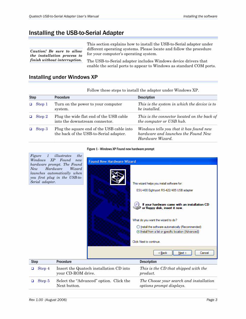
Figure 1 - Windows XP Found new hardware prompt
Step Procedure Description
Step 4 Insert the Quatech installation CD into your CD-ROM drive.
This is the CD that shipped with the product.
Step 5 Select the “Advanced” option. Click the Next button.
The Choose your search and installation options prompt displays.
Figure 1 illustrates the Windows XP Found new hardware prompt. The Found New Hardware Wizard launches automatically when you first plug in the USB-to-Serial adapter.
Rev 1.00 (August 2006) Page 3
Installing the software Quatech USB-to-Serial Adapter User’s Manual
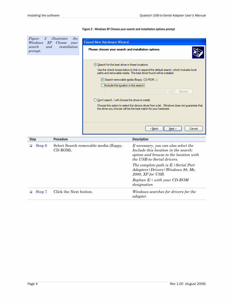
Figure 2 - Windows XP Choose your search and installation options prompt
Step Procedure Description
Step 6 Select Search removable media (floppy, CD-ROM).
If necessary, you can also select the Include this location in the search: option and browse to the location with the USB-to-Serial drivers. The complete path is E:\Serial Port Adapters\Drivers\Windows 98, Me, 2000, XP for USB. Replace E:\ with your CD-ROM designation
Step 7 Click the Next button. Windows searches for drivers for the adapter.
Figure 2 illustrates the Windows XP Choose your search and installation prompt.
Page 4 Rev 1.00 (August 2006)
Quatech USB-to-Serial Adapter User’s Manual Installing the software
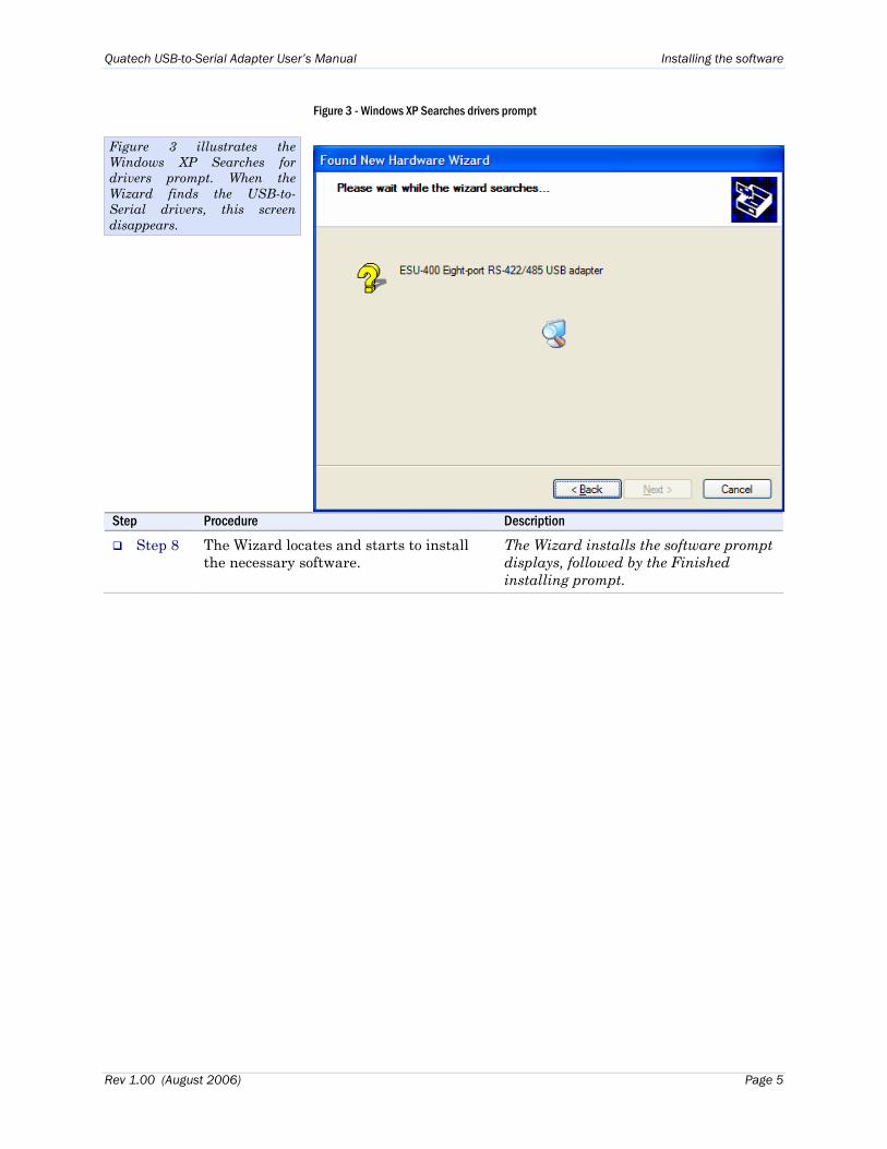
Figure 3 - Windows XP Searches drivers prompt
Step Procedure Description
Step 8 The Wizard locates and starts to install the necessary software.
The Wizard installs the software prompt displays, followed by the Finished installing prompt.
Figure 3 illustrates the Windows XP Searches for drivers prompt. When the Wizard finds the USB-to-Serial drivers, this screen disappears.
Rev 1.00 (August 2006) Page 5
Installing the software Quatech USB-to-Serial Adapter User’s Manual
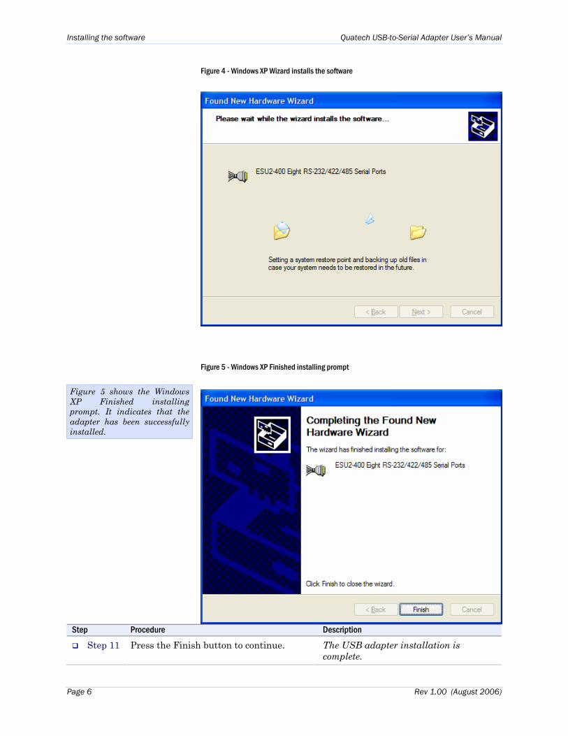
Figure 4 - Windows XP Wizard installs the software
Figure 5 - Windows XP Finished installing prompt
Step Procedure Description
Step 11 Press the Finish button to continue. The USB adapter installation is complete.
Figure 5 shows the Windows XP Finished installing prompt. It indicates that the adapter has been successfully installed.
Page 6 Rev 1.00 (August 2006)
Quatech USB-to-Serial Adapter User’s Manual Installing the software
Installing under Windows 2000
Follow these steps to install the USB-to-Serial adapter under Windows 2000.
Step Procedure Description
Step 1 Turn on the power to your computer system.
This is the system in which the device is to be installed.
Step 2 Plug the wide flat end of the USB cable into the downstream connector.
This is the connector located on the back of the computer of USB hub.
Step 3 Plug the square end of the USB cable into the back of the USB-to-Serial adapter.
Windows tells you that it has found new hardware and launches the Add New Hardware Wizard. The Found new hardware prompt displays.
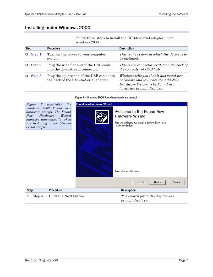
Figure 6 - Windows 2000 Found new hardware prompt
Step Procedure Description
Step 4 Click the Next button. The Search for or display drivers prompt displays.
Figure 6 illustrates the Windows 2000 Found new hardware prompt. The Found New Hardware Wizard launches automatically when you first plug in the USB-to-Serial adapter.
Rev 1.00 (August 2006) Page 7
Installing the software Quatech USB-to-Serial Adapter User’s Manual
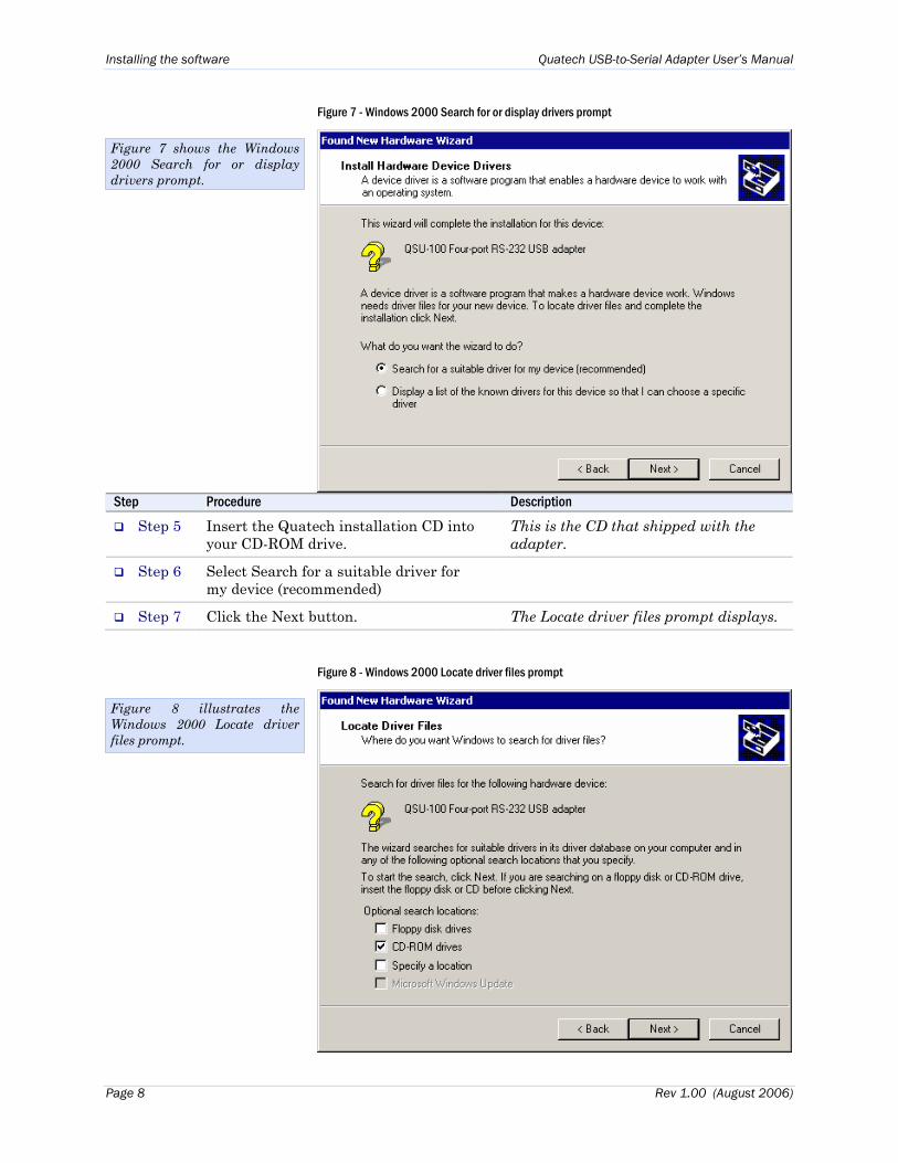
Figure 7 - Windows 2000 Search for or display drivers prompt
Figure 7 shows the Windows 2000 Search for or display drivers prompt.
Step Procedure Description
Step 5 Insert the Quatech installation CD into your CD-ROM drive.
This is the CD that shipped with the adapter.
Step 6 Select Search for a suitable driver for my device (recommended)
Step 7 Click the Next button. The Locate driver files prompt displays.
Figure 8 - Windows 2000 Locate driver files prompt
Figure 8 illustrates the Windows 2000 Locate driver files prompt.
Page 8 Rev 1.00 (August 2006)
Quatech USB-to-Serial Adapter User’s Manual Installing the software
Step Procedure Description
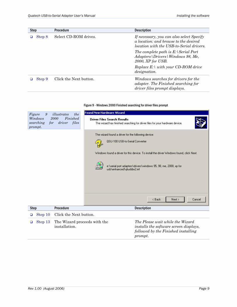
Step 8 Select CD-ROM drives. If necessary, you can also select Specify a location: and browse to the desired location with the USB-to-Serial drivers. The complete path is E:\Serial Port Adapters\Drivers\Windows 98, Me, 2000, XP for USB. Replace E:\ with your CD-ROM drive designation.
Step 9 Click the Next button. Windows searches for drivers for the adapter. The Finished searching for driver files prompt displays.
Figure 9 - Windows 2000 Finished searching for driver files prompt
Step Procedure Description
Step 10 Click the Next button.
Step 13 The Wizard proceeds with the installation.
The Please wait while the Wizard installs the software screen displays, followed by the Finished installing prompt.
Figure 9 illustrates the Windows 2000 Finished searching for driver files prompt.
Rev 1.00 (August 2006) Page 9
Installing the software Quatech USB-to-Serial Adapter User’s Manual
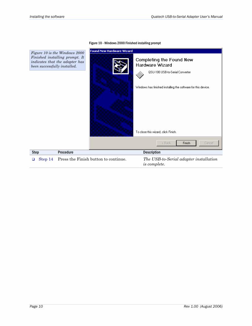
Figure 10 - Windows 2000 Finished installing prompt
Figure 10 is the Windows 2000 Finished installing prompt. It indicates that the adapter has been successfully installed.
Step Procedure Description
Step 14 Press the Finish button to continue. The USB-to-Serial adapter installation is complete.
Page 10 Rev 1.00 (August 2006)
Quatech USB-to-Serial Adapter User’s Manual Installing the software
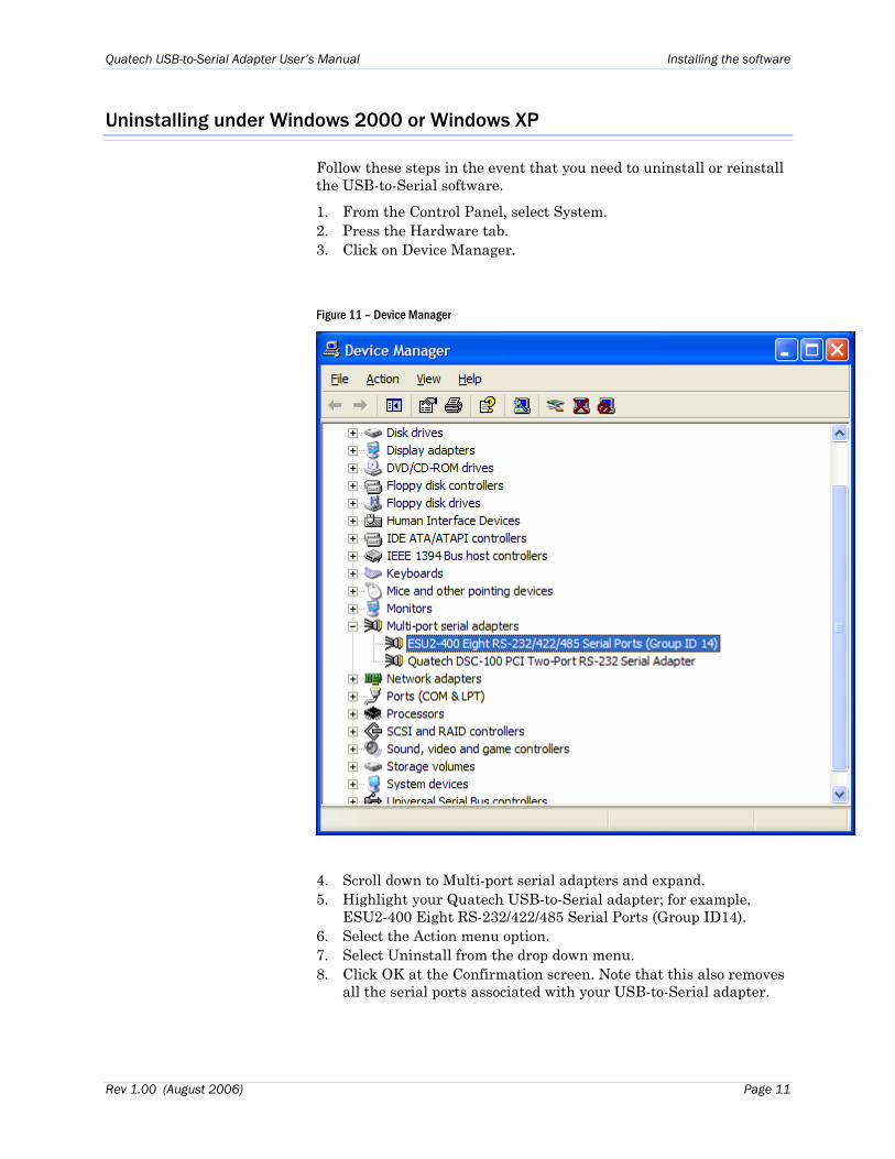
Uninstalling under Windows 2000 or Windows XP
Follow these steps in the event that you need to uninstall or reinstall the USB-to-Serial software.
1. From the Control Panel, select System. 2. Press the Hardware tab. 3. Click on Device Manager.
Figure 11 – Device Manager
4. Scroll down to Multi-port serial adapters and expand. 5. Highlight your Quatech USB-to-Serial adapter; for example,
ESU2-400 Eight RS-232/422/485 Serial Ports (Group ID14). 6. Select the Action menu option. 7. Select Uninstall from the drop down menu. 8. Click OK at the Confirmation screen. Note that this also removes
all the serial ports associated with your USB-to-Serial adapter.
Rev 1.00 (August 2006) Page 11
Making external connections Quatech USB-to-Serial Adapter User’s Manual
Making external connections
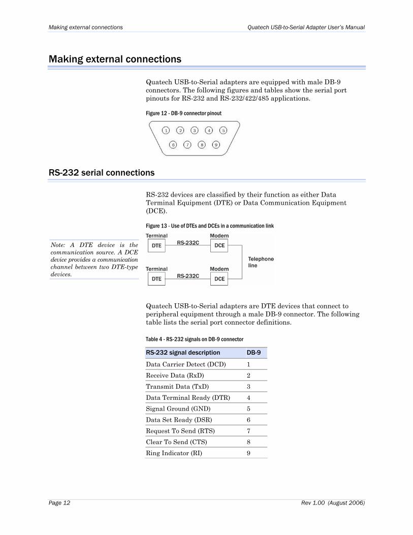
Quatech USB-to-Serial adapters are equipped with male DB-9 connectors. The following figures and tables show the serial port pinouts for RS-232 and RS-232/422/485 applications.
Figure 12 - DB-9 connector pinout
RS-232 serial connections
RS-232 devices are classified by their function as either Data Terminal Equipment (DTE) or Data Communication Equipment (DCE).
Figure 13 - Use of DTEs and DCEs in a communication link
Note: A DTE device is the communication source. A DCE device provides a communication channel between two DTE-type devices.
Quatech USB-to-Serial adapters are DTE devices that connect to peripheral equipment through a male DB-9 connector. The following table lists the serial port connector definitions.
Table 4 - RS-232 signals on DB-9 connector
RS-232 signal description DB-9
Data Carrier Detect (DCD) 1 Receive Data (RxD) 2 Transmit Data (TxD) 3 Data Terminal Ready (DTR) 4 Signal Ground (GND) 5 Data Set Ready (DSR) 6 Request To Send (RTS) 7 Clear To Send (CTS) 8 Ring Indicator (RI) 9
Page 12 Rev 1.00 (August 2006)
Quatech USB-to-Serial Adapter User’s Manual l Making external connections
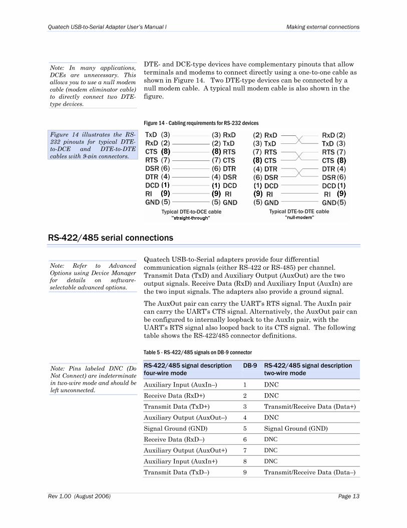
DTE- and DCE-type devices have complementary pinouts that allow terminals and modems to connect directly using a one-to-one cable as shown in Figure 14. Two DTE-type devices can be connected by a null modem cable. A typical null modem cable is also shown in the figure.
Note: In many applications, DCEs are unnecessary. This allows you to use a null modem cable (modem eliminator cable) to directly connect two DTE-type devices.
Figure 14 - Cabling requirements for RS-232 devices
RS-422/485 serial connections
Quatech USB-to-Serial adapters provide four differential communication signals (either RS-422 or RS-485) per channel. Transmit Data (TxD) and Auxiliary Output (AuxOut) are the two output signals. Receive Data (RxD) and Auxiliary Input (AuxIn) are the two input signals. The adapters also provide a ground signal. The AuxOut pair can carry the UART’s RTS signal. The AuxIn pair can carry the UART’s CTS signal. Alternatively, the AuxOut pair can be configured to internally loopback to the AuxIn pair, with the UART’s RTS signal also looped back to its CTS signal. The following table shows the RS-422/485 connector definitions.
Table 5 - RS-422/485 signals on DB-9 connector
RS-422/485 signal description four-wire mode
DB-9 RS-422/485 signal description two-wire mode
Auxiliary Input (AuxIn–) 1 DNC Receive Data (RxD+) 2 DNC Transmit Data (TxD+) 3 Transmit/Receive Data (Data+) Auxiliary Output (AuxOut–) 4 DNC Signal Ground (GND) 5 Signal Ground (GND) Receive Data (RxD–) 6 DNC Auxiliary Output (AuxOut+) 7 DNC Auxiliary Input (AuxIn+) 8 DNC Transmit Data (TxD–) 9 Transmit/Receive Data (Data–)
Note: Pins labeled DNC (Do Not Connect) are indeterminate in two-wire mode and should be left unconnected.
Note: Refer to Advanced Options using Device Manager for details on software-selectable advanced options.
Figure 14 illustrates the RS-232 pinouts for typical DTE-to-DCE and DTE-to-DTE cables with 9-pin connectors.
Rev 1.00 (August 2006) Page 13
Making external connections Quatech USB-to-Serial Adapter User’s Manual
Testing DB-9 serial ports in HyperTerminal
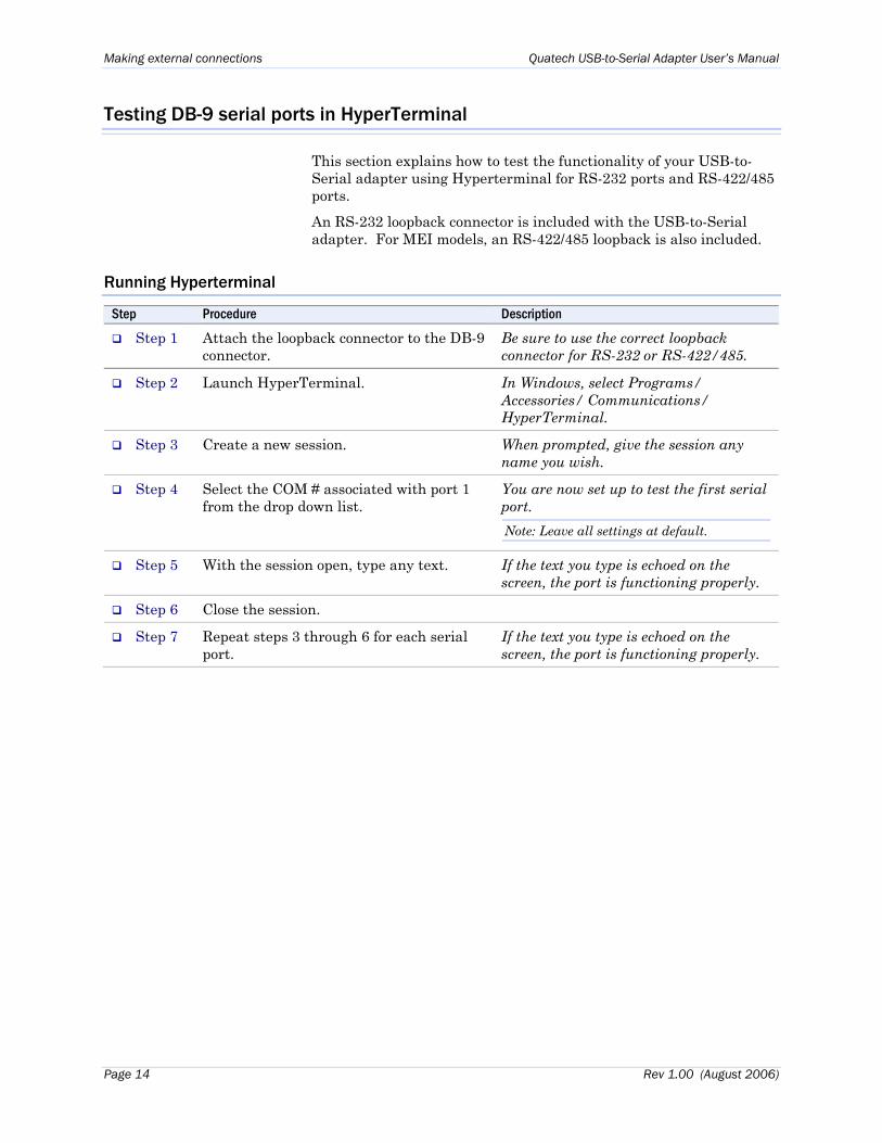
This section explains how to test the functionality of your USB-to-Serial adapter using Hyperterminal for RS-232 ports and RS-422/485 ports.
An RS-232 loopback connector is included with the USB-to-Serial adapter. For MEI models, an RS-422/485 loopback is also included.
Running Hyperterminal
Step Procedure Description
Step 1 Attach the loopback connector to the DB-9 connector.
Be sure to use the correct loopback connector for RS-232 or RS-422/485.
Step 2 Launch HyperTerminal. In Windows, select Programs/ Accessories/ Communications/ HyperTerminal.
Step 3 Create a new session. When prompted, give the session any name you wish.
Step 4 Select the COM # associated with port 1 from the drop down list.
You are now set up to test the first serial port. Note: Leave all settings at default.
Step 5 With the session open, type any text. If the text you type is echoed on the screen, the port is functioning properly.
Step 6 Close the session.
Step 7 Repeat steps 3 through 6 for each serial port.
If the text you type is echoed on the screen, the port is functioning properly.
Page 14 Rev 1.00 (August 2006)
Quatech USB-to-Serial Adapter User’s Manual Using configuration utilities
Using Device Manager
This section explains how to use Device Manager to view the properties of the serial ports enumerated by the USB-to-Serial adapter.
Accessing Device Manager
Step Procedure Description
Step 1 Select Start – Control Panel.
Step 2 Double click the System icon. The System Properties dialog box opens.
Step 3 Click the Hardware tab, and then press the Device Manager button.
Device Manager lists all the hardware devices that are registered inside the Windows registry.
Exploring Device Manager screens
Windows XP and 2000
Device Manager provides two property dialogs that apply to the USB-to-Serial adapter.
Ports (COM & LPT) device group property box Multi-port serial adapters device group property box
Use the Ports (COM & LPT) device group property box to view and set the port settings and to view device usage and driver information for the serial ports. Use the Multi-port serial adapters device group property box to view and set the advanced options and to view device usage and driver information for the USB-to-Serial adapter.
Step Procedure Description
Step 1 With Device Manager open, expand the Multi-port serial adapters device group.
Your USB-to-Serial adapter should appear in the list – for example, ESU2-400 Eight RS-232/422/485 Serial Ports (Group ID14).
Step 2 Double click the USB-to-Serial adapter. The Properties dialog box opens and displays the General tab.
Rev 1.00 (August 2006) Page 15
Using configuration utilities Quatech USB-to-Serial Adapter User’s Manual
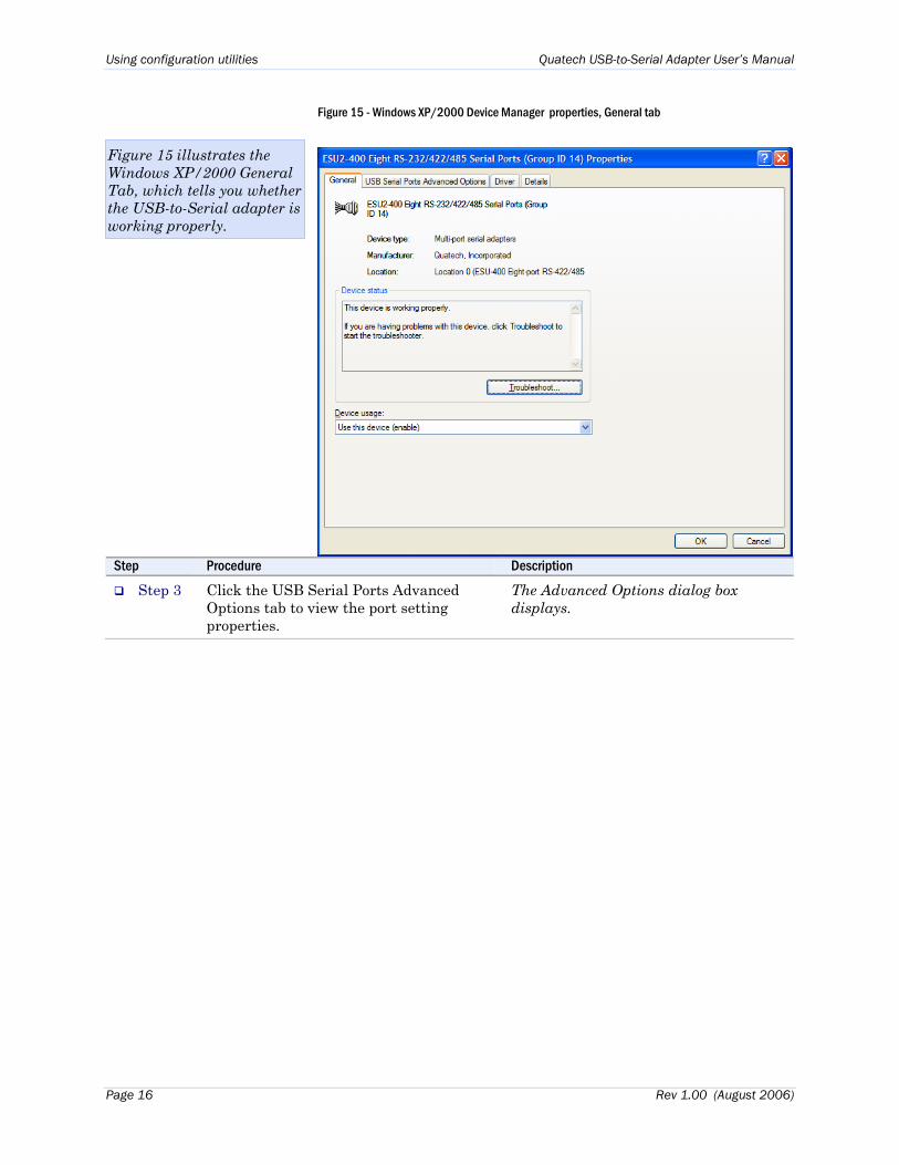
Figure 15 - Windows XP/2000 Device Manager properties, General tab
Step Procedure Description
Step 3 Click the USB Serial Ports Advanced Options tab to view the port setting properties.
The Advanced Options dialog box displays.
Figure 15 illustrates the Windows XP/2000 General Tab, which tells you whether the USB-to-Serial adapter is working properly.
Page 16 Rev 1.00 (August 2006)
Quatech USB-to-Serial Adapter User’s Manual Using configuration utilities
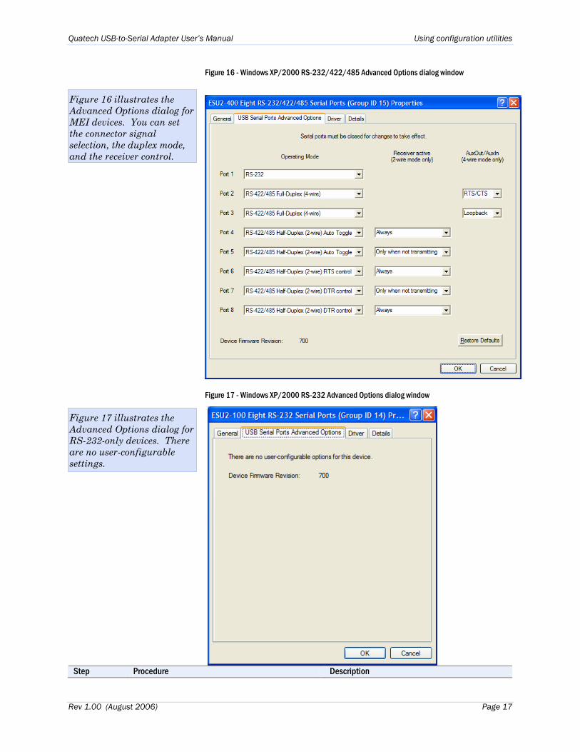
Figure 16 - Windows XP/2000 RS-232/422/485 Advanced Options dialog window
Figure 16 illustrates the Advanced Options dialog for MEI devices. You can set the connector signal selection, the duplex mode, and the receiver control.
Figure 17 - Windows XP/2000 RS-232 Advanced Options dialog window
Step Procedure Description
Figure 17 illustrates the Advanced Options dialog for RS-232-only devices. There are no user-configurable settings.
Rev 1.00 (August 2006) Page 17
Using configuration utilities Quatech USB-to-Serial Adapter User’s Manual
Step Procedure Description
Step 4 The RS-232 USB Serial Port Advanced Options dialog box displays the firmware revision of the USB-to-Serial adapter. The RS-422/485 Advanced Dialog box also lets you set the connector signals selection and the duplex mode, and receiver control.
There are no user-configurable settings for RS-232-only USB-to-Serial adapters. See the Setting advanced options section on page 44 section for details.
Step 5 Click Cancel to close the property box.
Step 6 With Device Manager open, expand the Ports (COM & LPT) device group.
The ports associated with the USB-to-Serial adapter should appear in the list of ports.
Step 7 Double click the desired port. The USB Serial Port Properties dialog box opens and displays the General tab.
Step 8 Click the Port settings tab. The Port Settings dialog box displays.
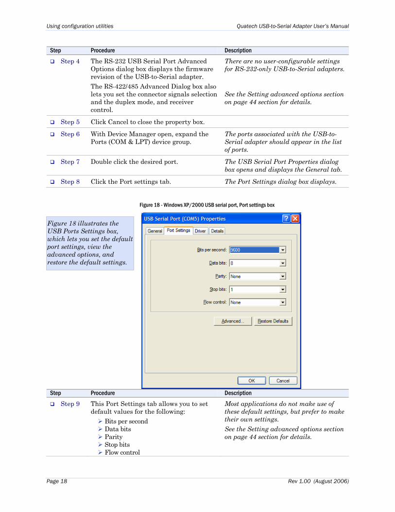
Figure 18 - Windows XP/2000 USB serial port, Port settings box
Step Procedure Description
Step 9 This Port Settings tab allows you to set default values for the following:
Bits per second Data bits Parity Stop bits Flow control
Most applications do not make use of these default settings, but prefer to make their own settings. See the Setting advanced options section on page 44 section for details.
Figure 18 illustrates the USB Ports Settings box, which lets you set the default port settings, view the advanced options, and restore the default settings.
Page 18 Rev 1.00 (August 2006)
Quatech USB-to-Serial Adapter User’s Manual Using configuration utilities
Step Procedure Description
Step 10 Press the Advanced button. The Advanced Options dialog box opens.
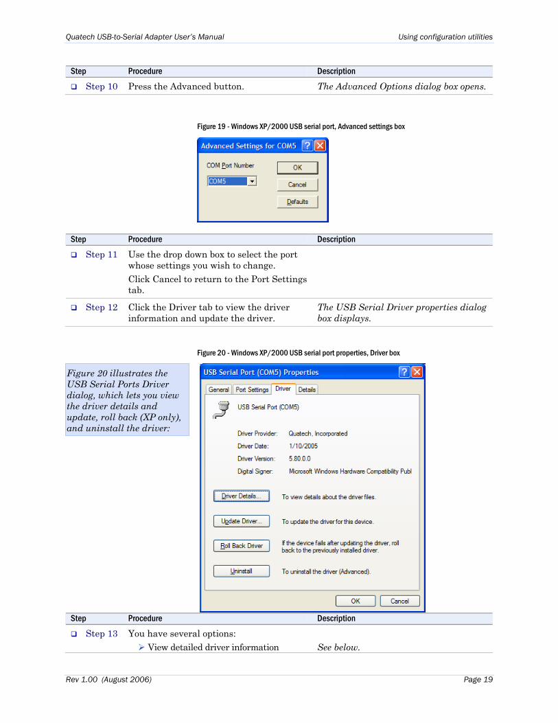
Figure 19 - Windows XP/2000 USB serial port, Advanced settings box
Step Procedure Description
Step 11 Use the drop down box to select the port whose settings you wish to change. Click Cancel to return to the Port Settings tab.
Step 12 Click the Driver tab to view the driver information and update the driver.
The USB Serial Driver properties dialog box displays.
Figure 20 - Windows XP/2000 USB serial port properties, Driver box
Step Procedure Description
Step 13 You have several options: View detailed driver information
See below.
Figure 20 illustrates the USB Serial Ports Driver dialog, which lets you view the driver details and update, roll back (XP only), and uninstall the driver:
Rev 1.00 (August 2006) Page 19
Using configuration utilities Quatech USB-to-Serial Adapter User’s Manual
Step Procedure Description
Update the device drivers
Uninstall your USB-to-Serial adapter.
Return to the previously installed driver. (XP only)
Save your changes and exit.
Abandon your changes and return to the Device Manager.
Don’t use this option. Uninstall the entire device instead by using the Driver dialog for the multiport serial adapter.
Step 14 Click the Driver Details button to view detailed driver information.
The Driver File Details dialog box opens. See the following figure.
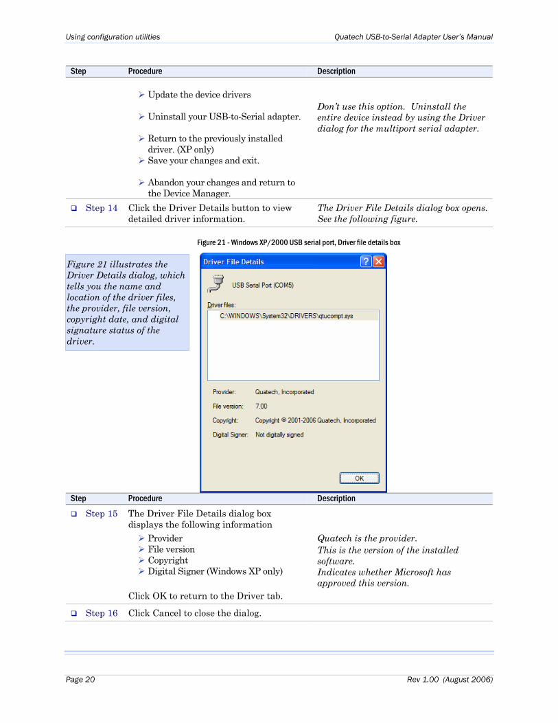
Figure 21 - Windows XP/2000 USB serial port, Driver file details box
Step Procedure Description
Step 15 The Driver File Details dialog box displays the following information
Provider File version Copyright Digital Signer (Windows XP only)
Click OK to return to the Driver tab.
Quatech is the provider. This is the version of the installed software. Indicates whether Microsoft has approved this version.
Step 16 Click Cancel to close the dialog.
Figure 21 illustrates the Driver Details dialog, which tells you the name and location of the driver files, the provider, file version, copyright date, and digital signature status of the driver.
Page 20 Rev 1.00 (August 2006)
Quatech USB-to-Serial Adapter User’s Manual Using configuration utilities
Setting advanced options (MEI adapters only)
The USB-to-Serial port advanced properties can be altered from the Device Manager window. Options for each serial port can be individually controlled.
Note: SSU2/DSU2/QSU2/ESU2-100 adapters have no user-selectable options.
Changes are applied:
• To all serial ports when the USB-to-Serial adapter is unplugged from the USB cable and plugged back in,
OR
• To a single port the next time an application opens the serial port.
Operating Mode (MEI adapters only)
RS-232 (default)
This mode configures the serial port to use an RS-232 electrical interface. Each UART's transmit drivers and receivers are always active in this mode.
Note: The serial port’s LED will glow red in RS-232 mode.
RS-422/485 Full Duplex (4-wire)
This mode configures the serial port to use an RS-422/485 electrical interface. Each UART's transmit drivers are always active in this mode. This mode allows simultaneous transmit and receive operation. Transmit and receive data move over separate dedicated pairs of conductors in the attached cable. The AuxOut/AuxIn signals are also available in 4-wire mode.
Note: The serial port’s LED will glow green in RS-422/485 mode.
RS-422/485 Half Duplex (2-wire) Auto-Toggle
This mode configures the serial port to use an RS-422/485 electrical interface. Transmit and receive operations share a single pair of conductors in the attached cable, so communication occurs in only one direction at a time. This configuration is often referred to as “multidrop.”
Note: The serial port’s LED will glow green in RS-422/485 mode.
Note: The Auto-Toggle mode is the best choice for most half-duplex scenarios. It offers the best performance and the best ease-of-use.
The transmit drivers are automatically enabled before data is transmitted, then disabled immediately after all data has been transmitted. This feature is implemented in hardware for near-instantaneous response.
Rev 1.00 (August 2006) Page 21
Using configuration utilities Quatech USB-to-Serial Adapter User’s Manual
RS-422/485 Half Duplex (2-wire) RTS control
This mode configures the serial port to use an RS-422/485 electrical interface. The half-duplex operation is the same as in the Auto-Toggle mode, except that the RTS signal is used to control the transmit drivers instead of the automatic control.
Note: The serial port’s LED will glow green in RS-422/485 mode.
The software application can disable the port's transmit drivers by deasserting the UART's RTS output. To allow transmission again, the software application must assert the RTS output.
RS-422/485 Half Duplex (2-wire) DTR control
This mode configures the serial port to use an RS-422/485 electrical interface. This mode operates the same as Half Duplex using RTS, except that the UART's DTR output is used.
Note: The serial port’s LED will glow green in RS-422/485 mode.
Receiver active… (MEI adapters only)
In RS-422/485 half-duplex operating modes, the serial port’s receivers can be set to be active all the time or to be active only when the port is not transmitting. The desired choice is selected from the dropdown box.
Always (default)
Select this option to force the receivers to be active all the time. This selection will cause the receiver to hear the echo of whatever the serial port transmits.
Only when not transmitting
This selection is useful for scenarios where the serial port should not hear the echo of its own transmissions. The receivers will be disabled whenever the serial port transmits data.
Page 22 Rev 1.00 (August 2006)
Quatech USB-to-Serial Adapter User’s Manual Using configuration utilities
AuxOut/AuxIn (MEI adapters only)
This setting determines which signals are routed to the AuxIn and AuxOut pins of the serial port connectors. Regardless of which setting is chosen, each UART's DTR output is internally looped back to its own DSR, DCD, and RI inputs.
Loopback (default)
Select this choice when only transmit and receive data signaling is required. Note: In half-duplex (2-wire)
modes, the UART’s RTS output is looped back to its CTS input.
Each UART's RTS output is internally looped back to its CTS input.
Each port's AuxIn signal pair is looped back to its AuxOut signal pair at the connector.
RTS/CTS
Select this choice when hardware flow control is required.
Each UART's RTS output and CTS input are routed to the AuxOut and AuxIn signal pairs, respectively.
Rev 1.00 (August 2006) Page 23
Using configuration utilities Quatech USB-to-Serial Adapter User’s Manual
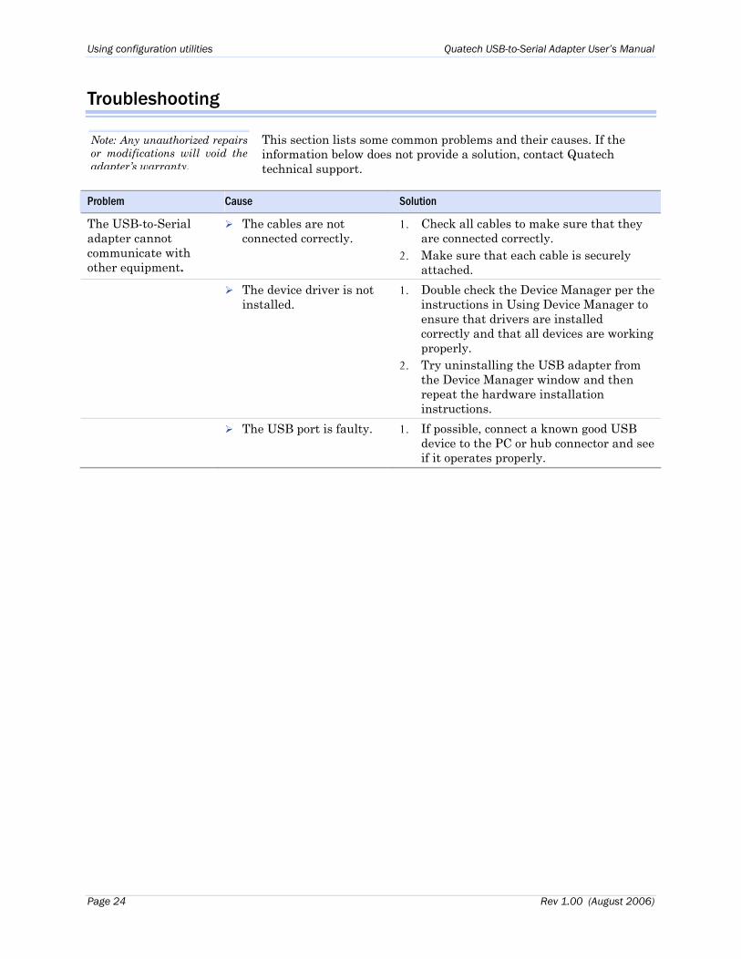
Troubleshooting
Note: Any unauthorized repairs or modifications will void the adapter’s warranty.
This section lists some common problems and their causes. If the information below does not provide a solution, contact Quatech technical support.
Problem Cause Solution
The USB-to-Serial adapter cannot communicate with other equipment.
The cables are not connected correctly.
1. Check all cables to make sure that they are connected correctly.
2. Make sure that each cable is securely attached.
The device driver is not installed.
1. Double check the Device Manager per the instructions in Using Device Manager to ensure that drivers are installed correctly and that all devices are working properly.
2. Try uninstalling the USB adapter from the Device Manager window and then repeat the hardware installation instructions.
The USB port is faulty. 1. If possible, connect a known good USB device to the PC or hub connector and see if it operates properly.
Page 24 Rev 1.00 (August 2006)
Quatech USB-to-Serial Adapter User’s Manual Appendix A
Appendix A
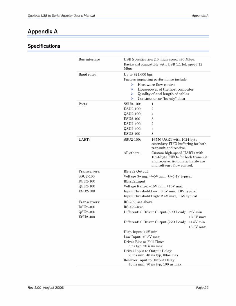
Specifications
Bus interface USB Specification 2.0, high speed 480 Mbps. Backward compatible with USB 1.1 full speed 12 Mbps.
Baud rates Up to 921,600 bps. Factors impacting performance include:
Hardware flow control Horsepower of the host computer Quality of and length of cables Continuous or “bursty” data
Ports SSU2-100: 1 DSU2-100: 2 QSU2-100: 4 ESU2-100 8 DSU2-400: 2 QSU2-400: 4 ESU2-400 8
UARTs SSU2-100: 16550 UART with 1024-byte secondary FIFO buffering for both transmit and receive.
All others: Custom high-speed UARTs with 1024-byte FIFOs for both transmit and receive. Automatic hardware and software flow control.
Transceivers: SSU2-100 DSU2-100 QSU2-100 ESU2-100
RS-232 OutputVoltage Swing: +/–5V min, +/–5.4V typical RS-232 Input Voltage Range: –15V min, +15V max Input Threshold Low: 0.6V min, 1.0V typical Input Threshold High: 2.4V max, 1.5V typical
Transceivers: DSU2-400 QSU2-400 ESU2-400
RS-232, see above. RS-422/485: Differential Driver Output (50Ω Load): +2V min +3.3V max Differential Driver Output (27Ω Load): +1.5V min +3.3V max High Input: +2V min Low Input: +0.8V max Driver Rise or Fall Time: 5 ns typ, 20.5 ns max Driver Input to Output Delay: 20 ns min, 40 ns typ, 60ns max Receiver Input to Output Delay: 40 ns min, 70 ns typ, 100 ns max
Rev 1.00 (August 2006) Page 25
Appendix A Quatech USB-to-Serial Adapter User’s Manual
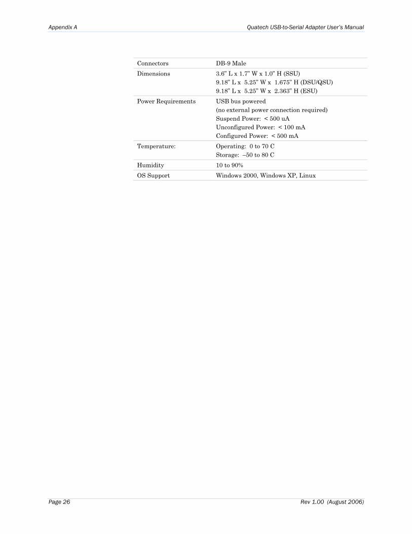
Connectors DB-9 Male Dimensions 3.6” L x 1.7” W x 1.0” H (SSU)
9.18” L x 5.25” W x 1.675” H (DSU/QSU) 9.18” L x 5.25” W x 2.363” H (ESU)
Power Requirements
USB bus powered (no external power connection required) Suspend Power: < 500 uA Unconfigured Power: < 100 mA Configured Power: < 500 mA
Temperature: Operating: 0 to 70 C Storage: –50 to 80 C
Humidity 10 to 90% OS Support Windows 2000, Windows XP, Linux
Page 26 Rev 1.00 (August 2006)
Quatech Freedom USB Adapter User’s Manual Appendix C
Appendix B
Warranty information
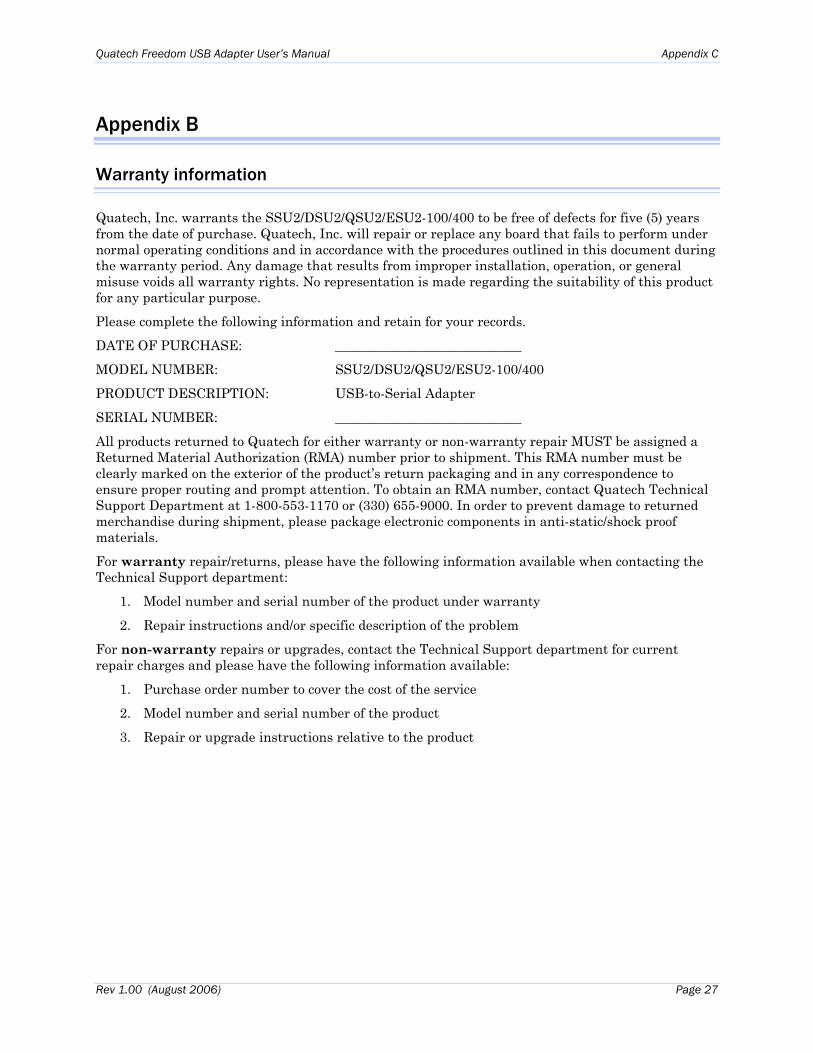
Quatech, Inc. warrants the SSU2/DSU2/QSU2/ESU2-100/400 to be free of defects for five (5) years from the date of purchase. Quatech, Inc. will repair or replace any board that fails to perform under normal operating conditions and in accordance with the procedures outlined in this document during the warranty period. Any damage that results from improper installation, operation, or general misuse voids all warranty rights. No representation is made regarding the suitability of this product for any particular purpose. Please complete the following information and retain for your records.
DATE OF PURCHASE: ____________________________
MODEL NUMBER: SSU2/DSU2/QSU2/ESU2-100/400
PRODUCT DESCRIPTION: USB-to-Serial Adapter
SERIAL NUMBER: ____________________________
All products returned to Quatech for either warranty or non-warranty repair MUST be assigned a Returned Material Authorization (RMA) number prior to shipment. This RMA number must be clearly marked on the exterior of the product’s return packaging and in any correspondence to ensure proper routing and prompt attention. To obtain an RMA number, contact Quatech Technical Support Department at 1-800-553-1170 or (330) 655-9000. In order to prevent damage to returned merchandise during shipment, please package electronic components in anti-static/shock proof materials.
For warranty repair/returns, please have the following information available when contacting the Technical Support department:
1. Model number and serial number of the product under warranty
2. Repair instructions and/or specific description of the problem
For non-warranty repairs or upgrades, contact the Technical Support department for current repair charges and please have the following information available:
1. Purchase order number to cover the cost of the service
2. Model number and serial number of the product
3. Repair or upgrade instructions relative to the product
Rev 1.00 (August 2006) Page 27