Embed Size (px)
Citation preview
MS-P575-5.GB.R3a
Installation manual
Connection system for solenoid valves andspool valves designed for fieldbus systems
PROFIBUS-DP, INTERBUS-S, DEVICE-NET
ValveConnectionSystem
GB

2
INSTALLATION
CAUTION !
To avoid malfunction of the automation system, please read and follow these instructions:
Ensure that the address size is correctly set. It may only be changed by qualified personnel. Make sure the VCS connector is correctly wired. The VCS circuit must always be looped through. Only use approved
profiled cables (see 2.1). Only use approved power supplies (see 2.1). Be sure the power supply is switched off prior to contacting the VCS cable. Risk of short circuit! To ensure personal safety and prevent damage to property, all maintenance and installation work must be carried out
by qualified personnel. Make sure to meet the electrical specifications of the system when operating it together with third-party equipment and
components. Install all power and signal cables such that inductive and capacitive interference of the automation functions is avoided. Take all safety precautions when coupling the inputs and outputs to the hardware and software to avoid undefined
conditions on the signal side of the automation system in case of line or conductor break. To ensure safe operation of the product, provide for suitable transportation, storage, installation and assembly as well
as proper operation and maintenance.
!
WARNING !
In the case of equipment with permanently installed connections (fixed devices/systems) without all-pole mainsdisconnect switch and/or switch fuses, incorporate a mains disconnect switch or fuse in the building installation. Theequipment must be connected to a ground conductor.
In the case of line powered equipment, check that the set nominal voltage range is in compliance with the local supplyvoltage prior to putting the equipment in service.
In the case of a 24V power supply, provide for safe electrical separation of low voltage. Only use power suppliesmanufactured in compliance with IEC 364-4-41.
Take precautions to ensure that a program interrupted due to drop or loss of voltage is properly resumed. Dangerousoperating conditions must be avoided at all times. If necessary, provide for an emergency shutdown.
To avoid operational failure, do not directly connect high frequency between 250 and 900 kHz to the VCS cable. In all cases in which faults occurring in automation equipment may result in substantial material or even personnel
damage, i.e. in which dangerous faults may occur, take additional external precautions or provide for additional externalequipment to ensure and/or force safe operation in the case of a fault (e.g. independent limiting switches, mechanicalinterlocks etc.).
!
COPYRIGHT © 2001 - ASCO/JOUCOMATIC - All rights reserved.
NOTICEThe information in this manual is subject to change without notice.
In no event shall ASCO/JOUCOMATIC be liable for technical or editorial errors or omissions. Neither is any liability assumed foraccidental or consequential damages arising out of or in connection with the supply or use of the information contained herein.
THIS MANUAL CONTAINS INFORMATION PROTECTED BY COPYRIGHT. NO PART OF THIS DOCUMENT MAY BE PHOTOCOPIEDOR REPRODUCED IN ANY FORM OR MANNER WHATSOEVER WITHOUT PRIOR WRITTEN PERMISSION FROMASCO/JOUCOMATIC.
This product complies with the essential requirements of the EMC Directive 89/336/EEC and its amendments. It is CE-approved. A separate Declaration of Conformity is available on request.A separate Declaration of Incorporation relating to the EU Directive 89/392/EEC Annex II B is available on request. Pleaseprovide ordering code and serial numbers of products concerned.
This product contains electronic components sensitive to electrostaticdischarge. An electrostatic discharge generated by a person or objectcoming in contact with the electrical components can damage or destroythe product.To avoid the risk of electrostatic discharge, please observe the handlingprecautions and recommendations contained in standard EN 100015-1.Do not connect or disconnect the device when it is energised.E S D
C A U T I O NOBSERVE PRECAUTIONS
FOR HANDLINGELETROSTATIC SENSITIVE
DEVICES
3
INSTALLATION
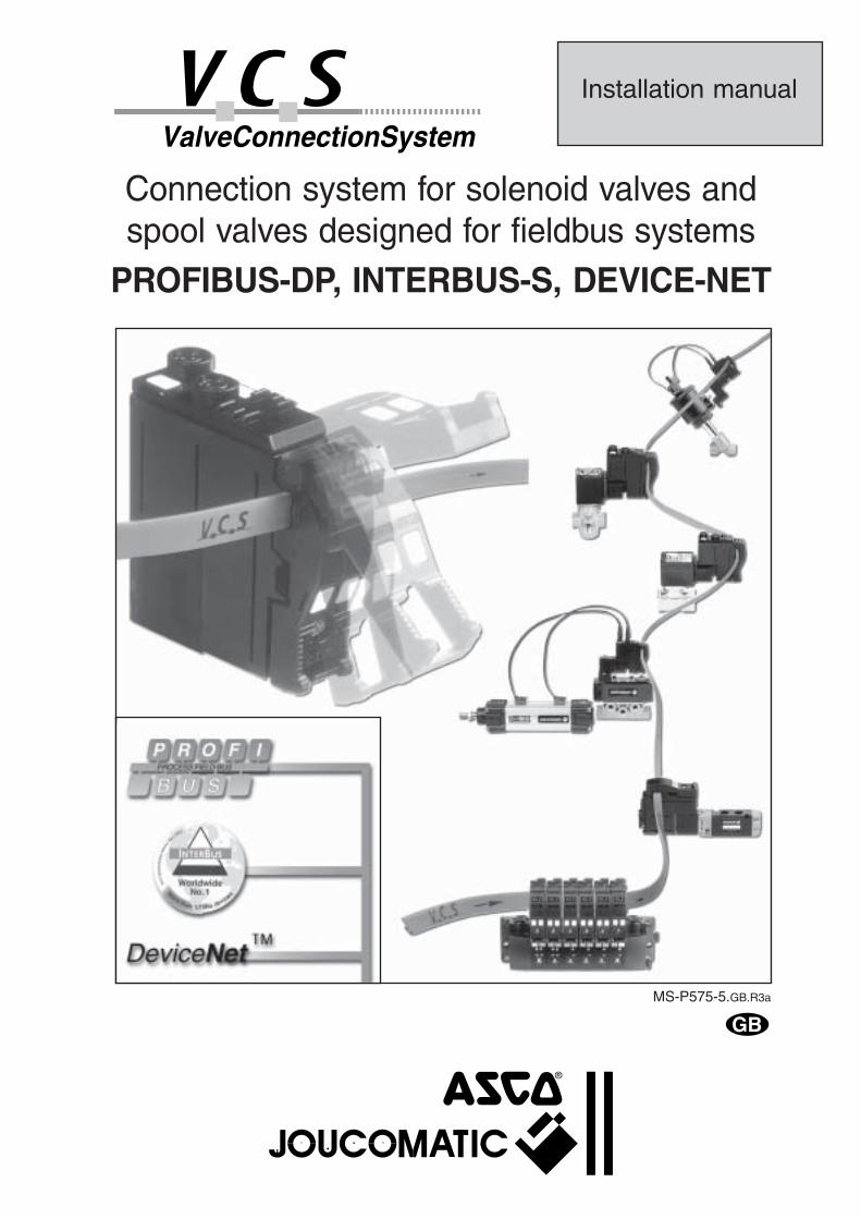
CONTENTS ________________________________________________________________Page
1. VCS - VALVE CONNECTION SYSTEM _______________________________________________________ 41.1 Structure_________________________________________________________________________________ 41.2 Diagnostics_______________________________________________________________________________ 5
2. SYSTEM COMPONENTS __________________________________________________________________ 62.1 Description _______________________________________________________________________________ 62.2 VCS connector ____________________________________________________________________________ 82.3 VCS cable _______________________________________________________________________________ 92.4 VCS interface ____________________________________________________________________________ 102.5 VCS power supply: 27V/max. 3.1 A ___________________________________________________________ 172.6 Power supply: 24V/max. 10 A _______________________________________________________________ 172.7 Accessories _____________________________________________________________________________ 18
3. POWER SUPPLY ON VCS LOOP __________________________________________________________ 203.1 Principle ________________________________________________________________________________ 203.2 Power supply of coils ≤ 2.4 W _______________________________________________________________ 203.3 Power supply of coils > 2.4 W (max. 24 W) _____________________________________________________ 253.4 Power supply of coils ≤ 2.4 W and > 2.4 W _____________________________________________________ 273.5 Supply of VCS loop with a standard 24V power supply ____________________________________________ 283.6 Selection charts (summary) _________________________________________________________________ 30
4. INSTALLATION INSTRUCTIONS __________________________________________________________ 324.1 Power supply connection ___________________________________________________________________ 324.2 Subsequent extension of the system __________________________________________________________ 334.3 VCS connector replacement ________________________________________________________________ 34
5. CONNECTION TO STANDARDISED FIELDBUS SYSTEM ______________________________________ 355.1 Profibus-DP _____________________________________________________________________________ 355.2 Interbus-S_______________________________________________________________________________ 365.3 DeviceNet_______________________________________________________________________________ 37
6. START-UP _____________________________________________________________________________ 396.1 Start-up instructions _______________________________________________________________________ 396.2 Automatic addressing______________________________________________________________________ 396.3 Test mode ______________________________________________________________________________ 406.4 Error mode ______________________________________________________________________________ 41
7. VCS DIAGNOSTIC SOFTWARE (VCS - DIAG) ________________________________________________ 427.1 Program installation _______________________________________________________________________ 427.2 Connection of the VCS interface _____________________________________________________________ 42
8. TECHNICAL CHARACTERISTICS __________________________________________________________ 438.1 Electrical characteristics ___________________________________________________________________ 438.2 Dimensions and weights ___________________________________________________________________ 44
9. MAINTENANCE AND CARE ______________________________________________________________ 46
10. MEGA 18 SPOOL VALVE ISLANDS WITH VCS CONNECTORS _________________________________ 4710.1 Presentation _____________________________________________________________________________ 4710.2 Dimensions and weights ___________________________________________________________________ 4710.3 Ordering information for MEGA island with VCS connectors________________________________________ 4810.4 Accessories _____________________________________________________________________________ 4910.5 Pressure supply of pilot valves ______________________________________________________________ 5210.6 Mounting and pneumatic accessories _________________________________________________________ 5210.7 Assembly of MEGAislands/VCS connectors ____________________________________________________ 5310.8 Joinable solenoid air operated MEGA spool valves_______________________________________________ 54
VCS Application Requirements Form _______________________________________________________________ 55
4
INSTALLATION
1. VCS - VALVE CONNECTION SYSTEM
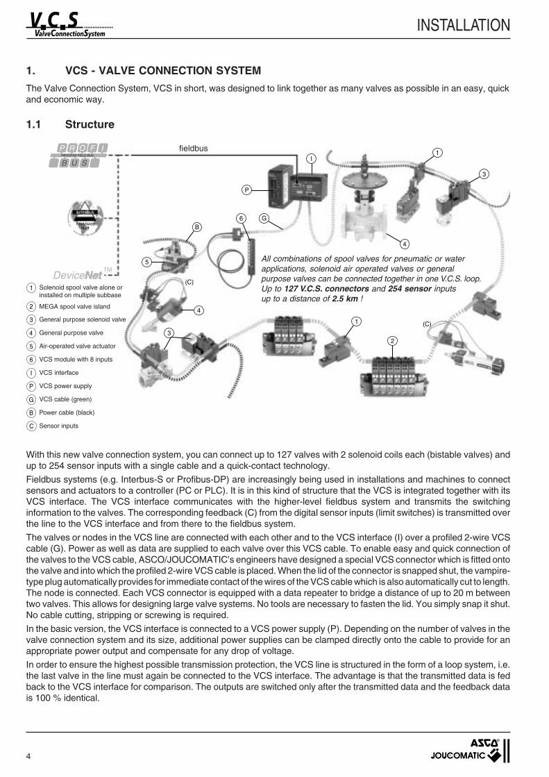
The Valve Connection System, VCS in short, was designed to link together as many valves as possible in an easy, quickand economic way.
1.1 Structure
With this new valve connection system, you can connect up to 127 valves with 2 solenoid coils each (bistable valves) andup to 254 sensor inputs with a single cable and a quick-contact technology.
Fieldbus systems (e.g. Interbus-S or Profibus-DP) are increasingly being used in installations and machines to connectsensors and actuators to a controller (PC or PLC). It is in this kind of structure that the VCS is integrated together with itsVCS interface. The VCS interface communicates with the higher-level fieldbus system and transmits the switchinginformation to the valves. The corresponding feedback (C) from the digital sensor inputs (limit switches) is transmitted overthe line to the VCS interface and from there to the fieldbus system.
The valves or nodes in the VCS line are connected with each other and to the VCS interface (I) over a profiled 2-wire VCScable (G). Power as well as data are supplied to each valve over this VCS cable. To enable easy and quick connection ofthe valves to the VCS cable, ASCO/JOUCOMATIC’s engineers have designed a special VCS connector which is fitted ontothe valve and into which the profiled 2-wire VCS cable is placed. When the lid of the connector is snapped shut, the vampire-type plug automatically provides for immediate contact of the wires of the VCS cable which is also automatically cut to length.The node is connected. Each VCS connector is equipped with a data repeater to bridge a distance of up to 20 m betweentwo valves. This allows for designing large valve systems. No tools are necessary to fasten the lid. You simply snap it shut.No cable cutting, stripping or screwing is required.
In the basic version, the VCS interface is connected to a VCS power supply (P). Depending on the number of valves in thevalve connection system and its size, additional power supplies can be clamped directly onto the cable to provide for anappropriate power output and compensate for any drop of voltage.
In order to ensure the highest possible transmission protection, the VCS line is structured in the form of a loop system, i.e.the last valve in the line must again be connected to the VCS interface. The advantage is that the transmitted data is fedback to the VCS interface for comparison. The outputs are switched only after the transmitted data and the feedback datais 100 % identical.
P
I
4
1
3
2
1
3
4
5
BG
(C)
(C)
6
All combinations of spool valves for pneumatic or waterapplications, solenoid air operated valves or generalpurpose valves can be connected together in one V.C.S. loop.Up to 127 V.C.S. connectors and 254 sensor inputsup to a distance of 2.5 km !
fieldbus
1 Solenoid spool valve alone orinstalled on multiple subbase
2 MEGA spool valve island
3 General purpose solenoid valve
4 General purpose valve
5 Air-operated valve actuator
6 VCS module with 8 inputs
I VCS interface
P VCS power supply
G VCS cable (green)
B Power cable (black)
C Sensor inputs
5
INSTALLATION
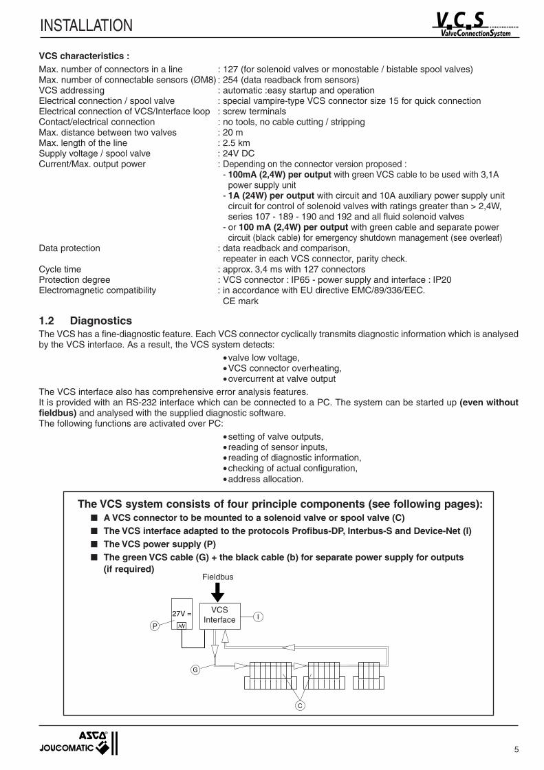
VCS characteristics :Max. number of connectors in a line : 127 (for solenoid valves or monostable / bistable spool valves)Max. number of connectable sensors (ØM8) : 254 (data readback from sensors)VCS addressing : automatic :easy startup and operationElectrical connection / spool valve : special vampire-type VCS connector size 15 for quick connectionElectrical connection of VCS/Interface loop : screw terminalsContact/electrical connection : no tools, no cable cutting / strippingMax. distance between two valves : 20 mMax. length of the line : 2.5 kmSupply voltage / spool valve : 24V DCCurrent/Max. output power : Depending on the connector version proposed :
- 100mA (2,4W) per output with green VCS cable to be used with 3,1Apower supply unit
- 1A (24W) per output with circuit and 10A auxiliary power supply unitcircuit for control of solenoid valves with ratings greater than > 2,4W,series 107 - 189 - 190 and 192 and all fluid solenoid valves
- or 100 mA (2,4W) per output with green cable and separate powercircuit (black cable) for emergency shutdown management (see overleaf)
Data protection : data readback and comparison,repeater in each VCS connector, parity check.
Cycle time : approx. 3,4 ms with 127 connectorsProtection degree : VCS connector : IP65 - power supply and interface : IP20Electromagnetic compatibility : in accordance with EU directive EMC/89/336/EEC.
CE mark
1.2 DiagnosticsThe VCS has a fine-diagnostic feature. Each VCS connector cyclically transmits diagnostic information which is analysedby the VCS interface. As a result, the VCS system detects:
•valve low voltage,•VCS connector overheating,•overcurrent at valve output
The VCS interface also has comprehensive error analysis features.It is provided with an RS-232 interface which can be connected to a PC. The system can be started up (even withoutfieldbus) and analysed with the supplied diagnostic software.The following functions are activated over PC:
•setting of valve outputs,• reading of sensor inputs,• reading of diagnostic information,•checking of actual configuration,•address allocation.
The VCS system consists of four principle components (see following pages): A VCS connector to be mounted to a solenoid valve or spool valve (C) The VCS interface adapted to the protocols Profibus-DP, Interbus-S and Device-Net (I) The VCS power supply (P) The green VCS cable (G) + the black cable (b) for separate power supply for outputs
(if required)
PI
C
VCSInterface
Fieldbus
6
INSTALLATION
2. SYSTEM COMPONENTS
2.1 Description
A. VCS connector (see chap. 2.2)
B. VCS interface (see chap. 2.4)
VCS connector size 15, 24V DC with 2 outputs max. 100 mA(connection exclusively over green cable)
VCS connector size 15, 24V DC with 2 outputs max. 100 mAand auxiliary power supply(connection with green and black cable)
VCS connector size 15, 24V DC with 1 output max. 1Aand auxiliary power supply(connection with green and black cable)
without input
with 2 inputs ØM8
single unit 881 57 803box of 8 881 00 600
single unit 881 57 805box of 8 881 00 601
single unit 881 57 949box of 8 881 00 602
single unit 881 57 951box of 8 881 00 603
single unit 881 57 807box of 8 881 00 604
single unit 881 57 809box of 8 881 00 605
Accessories Description Code
Standard VCS interface for connection with protocol:
VCS interface with 2 analog inputs/outputs 0 - 10V(e.g. for Sentronic) for connection with protocol:
9 male pin SUB-D connector for Profibus-DP - IP20
9 female pin SUB-D network input connector for Interbus-S - IP20 (BUS/IN)
9 male pin SUB-D network output connector for Interbus-S - IP20 (BUS/OUT)
Configuration diskette (.GSD / .EDS) for Profibus-DP and Device-Net
Diagnostic software for VCS / PC
RS232 cable for VCS interface/PC connection. Length: 1.8 m(only for use with diagnostic software)
VCS installation manual
Profibus-DP
Interbus-S
Device-Net
Profibus-DP
Interbus-S
Device-Net
Accessories Description Code
881 57 840
881 57 841
881 57 842
881 57 921
881 57 922
881 57 923
881 00 331
881 57 925
881 57 926
881 57 957
881 57 852
881 57 853
881 57 876
Adapter 15/22 for VCS connector mounting on coil size 22881 57 811to industrial standard (2 flat pins DIN46244 + earth, distance between pins 11mm)
Adapter 15/30 VCS connector mounting on coil with 2 pins + earth to ISO 4400 standard 881 57 812
without input
with 2 inputs ØM8
without input
with 2 inputs ØM8
(*) future product
(*)
(*)

7
INSTALLATION
881 57 889881 57 890881 57 857
881 57 940881 57 941881 57 928
881 57 855
881 57 854
881 57 856
881 57 927
881 57 851
978 02 256
978 02 257
C. Power supplies (see chap. 2.6)
D. Cables (see chap. 2.3)
E. VCS input modules
Accessories Description Code
VCS power supply 27V DC - 3.1A
Power supply for black power cable, 24V DC adjustable - 10A
881 57 845
881 57 846
Accessories Description Code
Flat profiled VCS cable, green, 2 wires - lengths:
Flat power cable, black, 2 wires - lengths:
VCS adapter (round/flat) for connection of additional VCS power supplyright-angle outlet with cable gland for round cable dia. 4 to 6mm
Extension module for flat VCS cable or power cable (flat/flat)
1 set of 10 self-adhesive flat cable mounting clips
1 set of heat-shrinkable 10 end caps for flat cable endsto ensure IP65 protection
1 set of 17 clip-on ID labels for spool valves and VCS connectors(Note: each component is supplied with 4 ID labels at delivery)
1 set of 10 guides for green VCS cableNote: each VCS connector is supplied with this guide + 1 spare guide
1 set of 10 guides for black power supply cableNote: each VCS connector is supplied with this guide + 1 spare guide
25 m50 m
100 m
25 m50 m
100 m
Accessories Description Code
VCS input module, 8 PNP inputs, 8 x M8 connectors
Straight 3 male pin input connector M8 (cable dia. 3.5 to 5mm)
Right-angle 3 male pin input connector M8 (cable dia. 3.5 to 5mm)
881 57 827
881 57 813
881 57 814
8
INSTALLATION
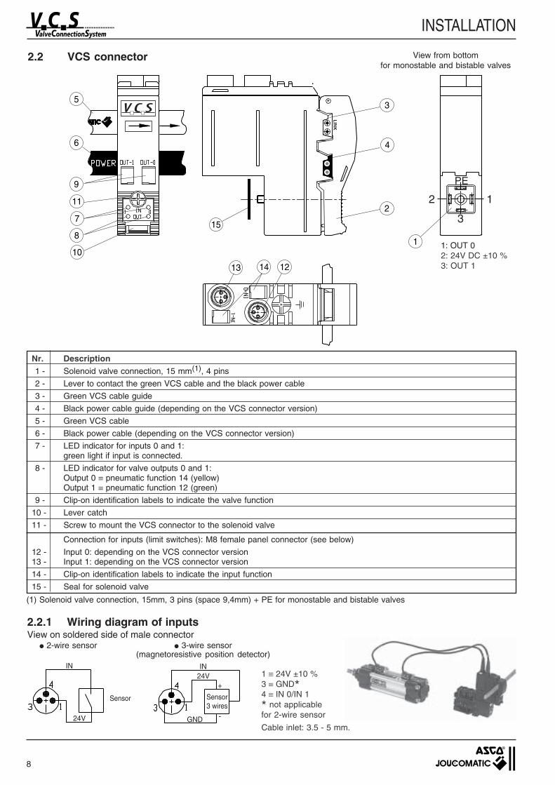
Nr. Description1 - Solenoid valve connection, 15 mm(1), 4 pins
2 - Lever to contact the green VCS cable and the black power cable
3 - Green VCS cable guide
4 - Black power cable guide (depending on the VCS connector version)
5 - Green VCS cable
6 - Black power cable (depending on the VCS connector version)
7 - LED indicator for inputs 0 and 1:green light if input is connected.
8 - LED indicator for valve outputs 0 and 1:Output 0 ≡ pneumatic function 14 (yellow)Output 1 ≡ pneumatic function 12 (green)
9 - Clip-on identification labels to indicate the valve function
10 - Lever catch
11 - Screw to mount the VCS connector to the solenoid valve
Connection for inputs (limit switches): M8 female panel connector (see below)
12 - Input 0: depending on the VCS connector version13 - Input 1: depending on the VCS connector version
14 - Clip-on identification labels to indicate the input function
15 - Seal for solenoid valve
24VIN
GND
+
-24V
IN
LIN
K
2 1
3
PE
5
6
9
11
7
8
10
13 14 12
15
1
3
4
2
1: OUT 02: 24V DC ±10 %3: OUT 1
Sensor
View from bottomfor monostable and bistable valves
2.2 VCS connector
1 ≡ 24V ±10 %3 ≡ GND*4 ≡ IN 0/IN 1
* not applicablefor 2-wire sensor
Cable inlet: 3.5 - 5 mm.
2.2.1 Wiring diagram of inputsView on soldered side of male connector
2-wire sensor 3-wire sensor(magnetoresistive position detector)
(1) Solenoid valve connection, 15mm, 3 pins (space 9,4mm) + PE for monostable and bistable valves
Sensor3 wires
9
INSTALLATION
13
2 6
5
4
!Power
off
A
A
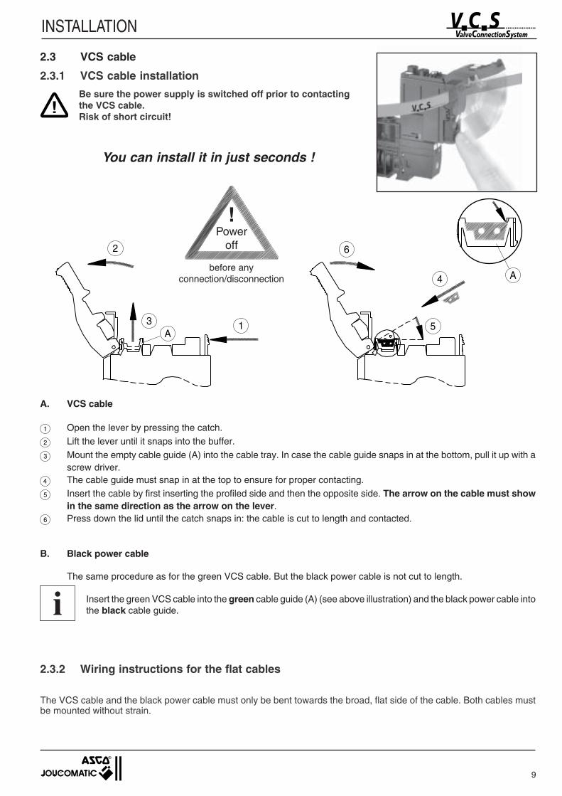
2.3 VCS cable
2.3.1 VCS cable installation
!Be sure the power supply is switched off prior to contactingthe VCS cable.Risk of short circuit!
2.3.2 Wiring instructions for the flat cables
The VCS cable and the black power cable must only be bent towards the broad, flat side of the cable. Both cables mustbe mounted without strain.
A. VCS cable
1 Open the lever by pressing the catch.
2 Lift the lever until it snaps into the buffer.
3 Mount the empty cable guide (A) into the cable tray. In case the cable guide snaps in at the bottom, pull it up with ascrew driver.
4 The cable guide must snap in at the top to ensure for proper contacting.
5 Insert the cable by first inserting the profiled side and then the opposite side. The arrow on the cable must showin the same direction as the arrow on the lever.
6 Press down the lid until the catch snaps in: the cable is cut to length and contacted.
B. Black power cable
The same procedure as for the green VCS cable. But the black power cable is not cut to length.
Insert the green VCS cable into the green cable guide (A) (see above illustration) and the black power cable intothe black cable guide.i
You can install it in just seconds !
before anyconnection/disconnection
10
INSTALLATION
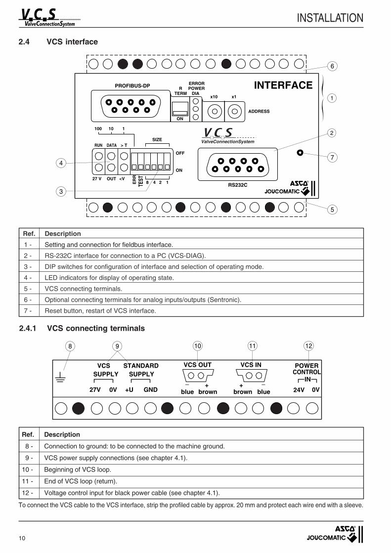
2.4.1 VCS connecting terminals
Ref. Description
1 - Setting and connection for fieldbus interface.
2 - RS-232C interface for connection to a PC (VCS-DIAG).
3 - DIP switches for configuration of interface and selection of operating mode.
4 - LED indicators for display of operating state.
5 - VCS connecting terminals.
6 - Optional connecting terminals for analog inputs/outputs (Sentronic).
7 - Reset button, restart of VCS interface.
Ref. Description
8 - Connection to ground: to be connected to the machine ground.
9 - VCS power supply connections (see chapter 4.1).
10 - Beginning of VCS loop.
11 - End of VCS loop (return).
12 - Voltage control input for black power cable (see chapter 4.1).
2.4 VCS interface
To connect the VCS cable to the VCS interface, strip the profiled cable by approx. 20 mm and protect each wire end with a sleeve.
INTERFACE
100 10 1
SIZE
OFF
ON
27 V
ER
ROUT <V
TEST
48 12
ValveConnectionSystem
PROFIBUS-DPTERM DIA
POWERERROR
R
x10 x1
ADDRESS
ON
RS232C
RUN DATA > T
1
2
7
6
5
3
4
IN
24V
POWERCONTROL
27V 0V +U GND
STANDARDVCSSUPPLY SUPPLY
_
blue brown+
bluebrown
VCS OUT VCS IN
0V_+
8 9 10 11 12

11
INSTALLATION
2.4.2 Analog input/output signals (Option)
Connecting terminals for proportional valve (sentronic)
Pin Signal Function
2 T×D Transmitted data
3 R×D Received data
5 GND Common ground
2.4.3 Assignment of RS-232C interface
A one-to-one cable in which R×D and T×D are not crossed is used for connection to a PC.Data transmission occurs without parity bit at a rate of 19200 baud.
Connection of SENTRONIC or PULSTRONIC to VCS interface terminals
Ref. Description
13 - Analog input/output signals 1 for proportional valve connection (Sentronic etc.)
14 - Analog input/output signals 2 for proportional valve connection (Sentronic etc.)
15 - Power supply connection for analog inputs/outputs (must be connected for analog input/output option)
SUP SETGND SET GND
SENTRONIC 1 SENTRONIC 2
SETSUP
24V GNDSETGND 24V
SUPPLYSENTRO
GND24V Feedbk Feedbk
13 14 15
24V Power supply 1 1
SUP - GND common ground 2 2
SET Setpoint (0 - 10V) 3 3
SET - GND - 4 -
Feedbk Feedback value (0 - 10V) 6 4 *
Signal Function SENTRONICPin assignment
PULSTRONICPin assignment
*) Only if the feedback (0-10V) option is used.
12
INSTALLATION
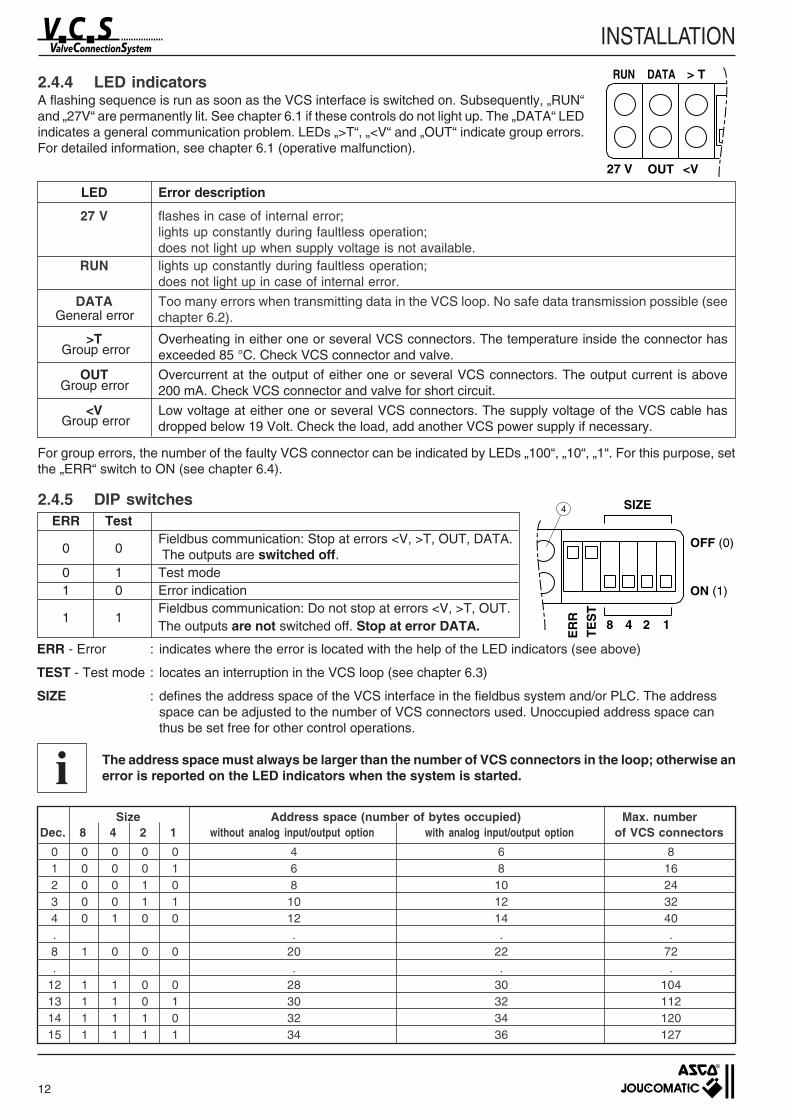
LED Error description
27 V flashes in case of internal error;lights up constantly during faultless operation;does not light up when supply voltage is not available.
RUN lights up constantly during faultless operation;does not light up in case of internal error.
DATA Too many errors when transmitting data in the VCS loop. No safe data transmission possible (seechapter 6.2).
>T Overheating in either one or several VCS connectors. The temperature inside the connector hasexceeded 85 °C. Check VCS connector and valve.
OUT Overcurrent at the output of either one or several VCS connectors. The output current is above200 mA. Check VCS connector and valve for short circuit.
<V Low voltage at either one or several VCS connectors. The supply voltage of the VCS cable hasdropped below 19 Volt. Check the load, add another VCS power supply if necessary.
General error
Group error
Group error
Group error
For group errors, the number of the faulty VCS connector can be indicated by LEDs „100“, „10“, „1“. For this purpose, setthe „ERR“ switch to ON (see chapter 6.4).
2.4.4 LED indicatorsA flashing sequence is run as soon as the VCS interface is switched on. Subsequently, „RUN“and „27V“ are permanently lit. See chapter 6.1 if these controls do not light up. The „DATA“ LEDindicates a general communication problem. LEDs „>T“, „<V“ and „OUT“ indicate group errors.For detailed information, see chapter 6.1 (operative malfunction).
ERR - Error : indicates where the error is located with the help of the LED indicators (see above)
TEST - Test mode : locates an interruption in the VCS loop (see chapter 6.3)
SIZE : defines the address space of the VCS interface in the fieldbus system and/or PLC. The addressspace can be adjusted to the number of VCS connectors used. Unoccupied address space canthus be set free for other control operations.
The address space must always be larger than the number of VCS connectors in the loop; otherwise anerror is reported on the LED indicators when the system is started.
0 0 0 0 0 4 6 81 0 0 0 1 6 8 162 0 0 1 0 8 10 243 0 0 1 1 10 12 324 0 1 0 0 12 14 40. . . .8 1 0 0 0 20 22 72. . . .
12 1 1 0 0 28 30 10413 1 1 0 1 30 32 11214 1 1 1 0 32 34 12015 1 1 1 1 34 36 127
ERR Test
0 0Fieldbus communication: Stop at errors <V, >T, OUT, DATA. The outputs are switched off.
0 1 Test mode1 0 Error indication
1 1Fieldbus communication: Do not stop at errors <V, >T, OUT.The outputs are not switched off. Stop at error DATA.
2.4.5 DIP switches
Size Address space (number of bytes occupied) Max. numberDec. 8 4 2 1 without analog input/output option with analog input/output option of VCS connectors
27 V OUT <V
RUN DATA > T
SIZE
OFF (0)
ON (1)
ER
R
TE
ST
48 12
4
i
13
INSTALLATION
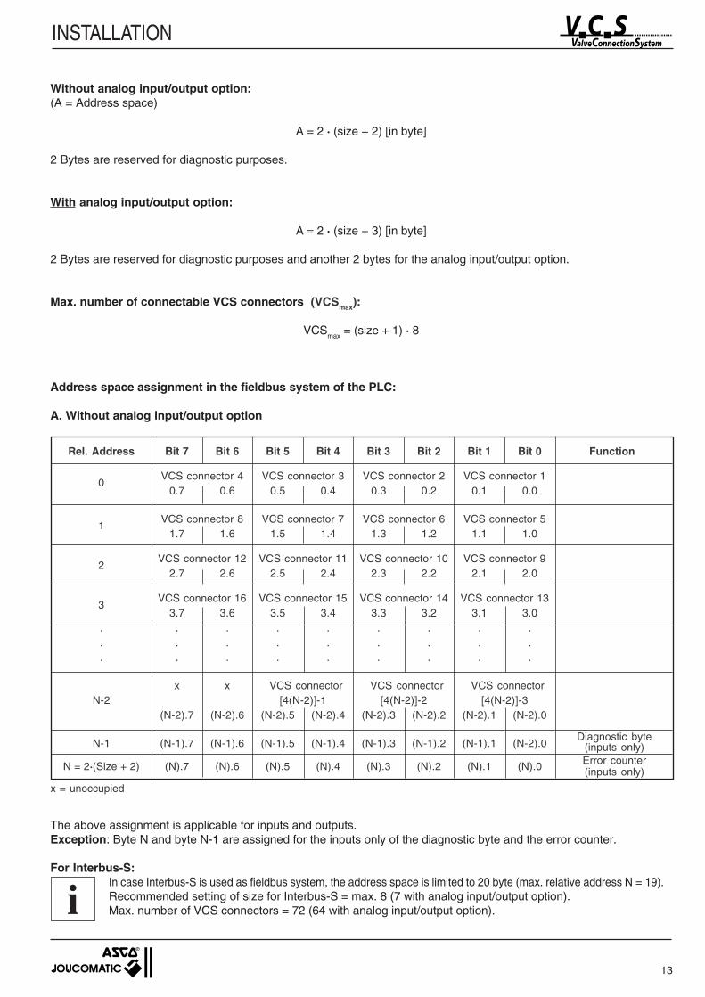
Rel. Address Bit 7 Bit 6 Bit 5 Bit 4 Bit 3 Bit 2 Bit 1 Bit 0 Function
0VCS connector 4 VCS connector 3 VCS connector 2 VCS connector 1
0.7 0.6 0.5 0.4 0.3 0.2 0.1 0.0
1VCS connector 8 VCS connector 7 VCS connector 6 VCS connector 5
1.7 1.6 1.5 1.4 1.3 1.2 1.1 1.0
2VCS connector 12 VCS connector 11 VCS connector 10 VCS connector 9
2.7 2.6 2.5 2.4 2.3 2.2 2.1 2.0
3VCS connector 16 VCS connector 15 VCS connector 14 VCS connector 13
3.7 3.6 3.5 3.4 3.3 3.2 3.1 3.0. . . . . . . . .. . . . . . . . .. . . . . . . . .
x x VCS connector VCS connector VCS connectorN-2 [4(N-2)]-1 [4(N-2)]-2 [4(N-2)]-3
(N-2).7 (N-2).6 (N-2).5 (N-2).4 (N-2).3 (N-2).2 (N-2).1 (N-2).0
N-1 (N-1).7 (N-1).6 (N-1).5 (N-1).4 (N-1).3 (N-1).2 (N-1).1 (N-2).0
N = 2·(Size + 2) (N).7 (N).6 (N).5 (N).4 (N).3 (N).2 (N).1 (N).0
Diagnostic byte(inputs only)Error counter(inputs only)
The above assignment is applicable for inputs and outputs.Exception: Byte N and byte N-1 are assigned for the inputs only of the diagnostic byte and the error counter.
For Interbus-S:In case Interbus-S is used as fieldbus system, the address space is limited to 20 byte (max. relative address N = 19).Recommended setting of size for Interbus-S = max. 8 (7 with analog input/output option).Max. number of VCS connectors = 72 (64 with analog input/output option).
x = unoccupied
Without analog input/output option:(A = Address space)
A = 2 · (size + 2) [in byte]
2 Bytes are reserved for diagnostic purposes.
With analog input/output option:
A = 2 · (size + 3) [in byte]
2 Bytes are reserved for diagnostic purposes and another 2 bytes for the analog input/output option.
Max. number of connectable VCS connectors (VCSmax):
VCSmax = (size + 1) · 8
Address space assignment in the fieldbus system of the PLC:
A. Without analog input/output option
i
14
INSTALLATION
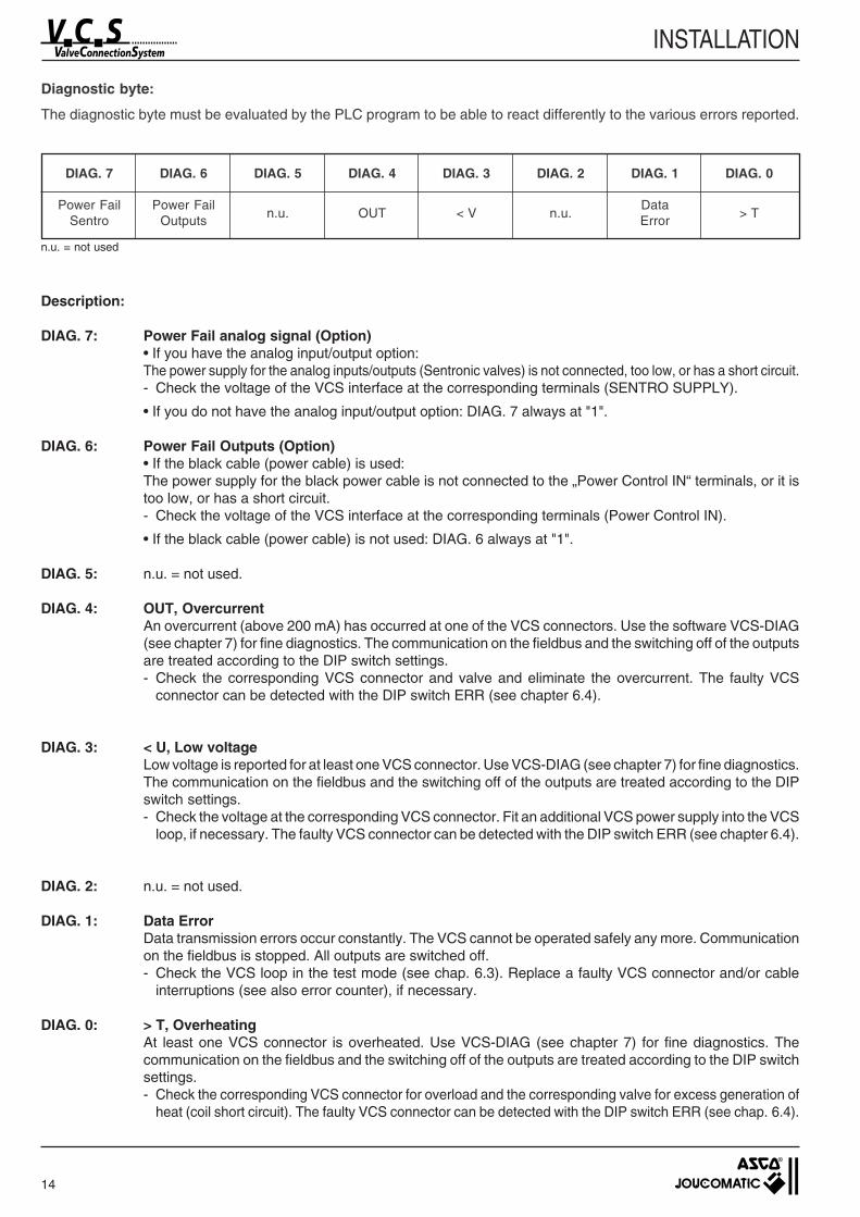
Diagnostic byte:
The diagnostic byte must be evaluated by the PLC program to be able to react differently to the various errors reported.
DIAG. 7 DIAG. 6 DIAG. 5 DIAG. 4 DIAG. 3 DIAG. 2 DIAG. 1 DIAG. 0
Power Fail Power Failn.u. OUT < V n.u.
Data> T
Sentro Outputs Error
n.u. = not used
Description:
DIAG. 7: Power Fail analog signal (Option)• If you have the analog input/output option:The power supply for the analog inputs/outputs (Sentronic valves) is not connected, too low, or has a short circuit.- Check the voltage of the VCS interface at the corresponding terminals (SENTRO SUPPLY).
• If you do not have the analog input/output option: DIAG. 7 always at "1".
DIAG. 6: Power Fail Outputs (Option)• If the black cable (power cable) is used:The power supply for the black power cable is not connected to the „Power Control IN“ terminals, or it istoo low, or has a short circuit.- Check the voltage of the VCS interface at the corresponding terminals (Power Control IN).
• If the black cable (power cable) is not used: DIAG. 6 always at "1".
DIAG. 5: n.u. = not used.
DIAG. 4: OUT, OvercurrentAn overcurrent (above 200 mA) has occurred at one of the VCS connectors. Use the software VCS-DIAG(see chapter 7) for fine diagnostics. The communication on the fieldbus and the switching off of the outputsare treated according to the DIP switch settings.- Check the corresponding VCS connector and valve and eliminate the overcurrent. The faulty VCS
connector can be detected with the DIP switch ERR (see chapter 6.4).
DIAG. 3: < U, Low voltageLow voltage is reported for at least one VCS connector. Use VCS-DIAG (see chapter 7) for fine diagnostics.The communication on the fieldbus and the switching off of the outputs are treated according to the DIPswitch settings.- Check the voltage at the corresponding VCS connector. Fit an additional VCS power supply into the VCS
loop, if necessary. The faulty VCS connector can be detected with the DIP switch ERR (see chapter 6.4).
DIAG. 2: n.u. = not used.
DIAG. 1: Data ErrorData transmission errors occur constantly. The VCS cannot be operated safely any more. Communicationon the fieldbus is stopped. All outputs are switched off.- Check the VCS loop in the test mode (see chap. 6.3). Replace a faulty VCS connector and/or cable
interruptions (see also error counter), if necessary.
DIAG. 0: > T, OverheatingAt least one VCS connector is overheated. Use VCS-DIAG (see chapter 7) for fine diagnostics. Thecommunication on the fieldbus and the switching off of the outputs are treated according to the DIP switchsettings.- Check the corresponding VCS connector for overload and the corresponding valve for excess generation of
heat (coil short circuit). The faulty VCS connector can be detected with the DIP switch ERR (see chap. 6.4).
15
INSTALLATION
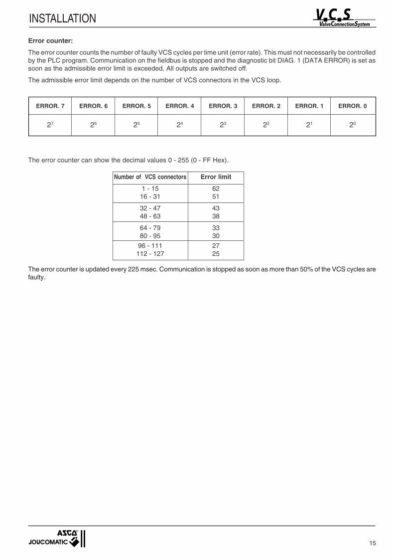
ERROR. 7 ERROR. 6 ERROR. 5 ERROR. 4 ERROR. 3 ERROR. 2 ERROR. 1 ERROR. 0
27 26 25 24 23 22 21 20
The error counter can show the decimal values 0 - 255 (0 - FF Hex).
Number of VCS connectors Error limit
1 - 15 6216 - 31 51
32 - 47 4348 - 63 38
64 - 79 3380 - 95 30
96 - 111 27112 - 127 25
The error counter is updated every 225 msec. Communication is stopped as soon as more than 50% of the VCS cycles arefaulty.
Error counter:
The error counter counts the number of faulty VCS cycles per time unit (error rate). This must not necessarily be controlledby the PLC program. Communication on the fieldbus is stopped and the diagnostic bit DIAG. 1 (DATA ERROR) is set assoon as the admissible error limit is exceeded. All outputs are switched off.
The admissible error limit depends on the number of VCS connectors in the VCS loop.
16
INSTALLATION
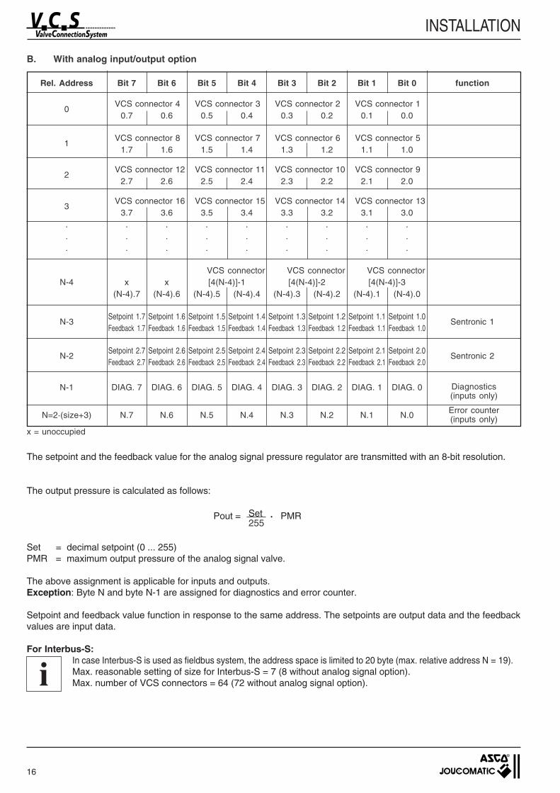
B. With analog input/output option
Rel. Address Bit 7 Bit 6 Bit 5 Bit 4 Bit 3 Bit 2 Bit 1 Bit 0 function
x = unoccupied
0VCS connector 4 VCS connector 3 VCS connector 2 VCS connector 1
0.7 0.6 0.5 0.4 0.3 0.2 0.1 0.0
1VCS connector 8 VCS connector 7 VCS connector 6 VCS connector 5
1.7 1.6 1.5 1.4 1.3 1.2 1.1 1.0
2VCS connector 12 VCS connector 11 VCS connector 10 VCS connector 9
2.7 2.6 2.5 2.4 2.3 2.2 2.1 2.0
3VCS connector 16 VCS connector 15 VCS connector 14 VCS connector 13
3.7 3.6 3.5 3.4 3.3 3.2 3.1 3.0. . . . . . . . .. . . . . . . . .. . . . . . . . .
VCS connector VCS connector VCS connectorN-4 x x [4(N-4)]-1 [4(N-4)]-2 [4(N-4)]-3
(N-4).7 (N-4).6 (N-4).5 (N-4).4 (N-4).3 (N-4).2 (N-4).1 (N-4).0
N-3Setpoint 1.7 Setpoint 1.6 Setpoint 1.5 Setpoint 1.4 Setpoint 1.3 Setpoint 1.2 Setpoint 1.1 Setpoint 1.0
Sentronic 1Feedback 1.7 Feedback 1.6 Feedback 1.5 Feedback 1.4 Feedback 1.3 Feedback 1.2 Feedback 1.1 Feedback 1.0
N-2Setpoint 2.7 Setpoint 2.6 Setpoint 2.5 Setpoint 2.4 Setpoint 2.3 Setpoint 2.2 Setpoint 2.1 Setpoint 2.0
Sentronic 2Feedback 2.7 Feedback 2.6 Feedback 2.5 Feedback 2.4 Feedback 2.3 Feedback 2.2 Feedback 2.1 Feedback 2.0
N-1 DIAG. 7 DIAG. 6 DIAG. 5 DIAG. 4 DIAG. 3 DIAG. 2 DIAG. 1 DIAG. 0
N=2·(size+3) N.7 N.6 N.5 N.4 N.3 N.2 N.1 N.0
255
The setpoint and the feedback value for the analog signal pressure regulator are transmitted with an 8-bit resolution.
The output pressure is calculated as follows:
Pout = Set · PMR
Set = decimal setpoint (0 ... 255)PMR = maximum output pressure of the analog signal valve.
The above assignment is applicable for inputs and outputs.Exception: Byte N and byte N-1 are assigned for diagnostics and error counter.
Setpoint and feedback value function in response to the same address. The setpoints are output data and the feedbackvalues are input data.
For Interbus-S:In case Interbus-S is used as fieldbus system, the address space is limited to 20 byte (max. relative address N = 19).Max. reasonable setting of size for Interbus-S = 7 (8 without analog signal option).Max. number of VCS connectors = 64 (72 without analog signal option).
Diagnostics(inputs only)
Error counter(inputs only)
i
17
INSTALLATION
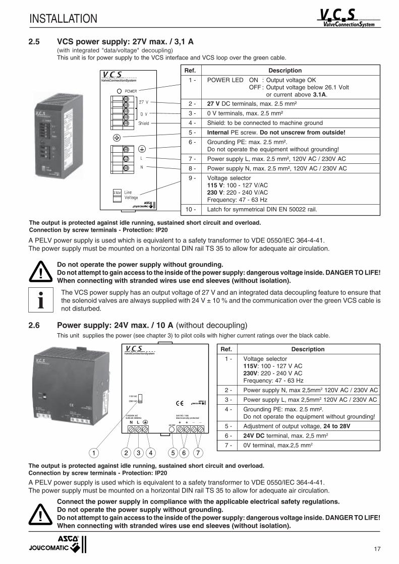
2.5 VCS power supply: 27V max. / 3,1 A(with integrated "data/voltage" decoupling)This unit is for power supply to the VCS interface and VCS loop over the green cable.
!
A PELV power supply is used which is equivalent to a safety transformer to VDE 0550/IEC 364-4-41.The power supply must be mounted on a horizontal DIN rail TS 35 to allow for adequate air circulation.
Do not operate the power supply without grounding.Do not attempt to gain access to the inside of the power supply: dangerous voltage inside. DANGER TO LIFE!When connecting with stranded wires use end sleeves (without isolation).
The VCS power supply has an output voltage of 27 V and an integrated data decoupling feature to ensure thatthe solenoid valves are always supplied with 24 V ± 10 % and the communication over the green VCS cable isnot disturbed.
2.6 Power supply: 24V max. / 10 A (without decoupling)This unit supplies the power (see chapter 3) to pilot coils with higher current ratings over the black cable.
Ref. Description
1 - POWER LED ON : Output voltage OKOFF : Output voltage below 26.1 Volt
or current above 3.1A.
2 - 27 V DC terminals, max. 2.5 mm²
3 - 0 V terminals, max. 2.5 mm²
4 - Shield: to be connected to machine ground
5 - Internal PE screw. Do not unscrew from outside!
6 - Grounding PE: max. 2.5 mm².Do not operate the equipment without grounding!
7 - Power supply L, max. 2.5 mm², 120V AC / 230V AC
8 - Power supply N, max. 2.5 mm², 120V AC / 230V AC
9 - Voltage selector115 V: 100 - 127 V/AC230 V: 220 - 240 V/ACFrequency: 47 - 63 Hz
10 - Latch for symmetrical DIN EN 50022 rail.
ValveConnectionSystem
24V DC / 10AElectronically protected
+ + _ _24-28V
115/230V AC8.0/2.8A 50/60Hz
N L
115V AC
230V AC
ValveConnectionSystem
1 2 3 4 5 6 7
Ref. Description
1 - Voltage selector115V: 100 - 127 V AC230V: 220 - 240 V ACFrequency: 47 - 63 Hz
2 - Power supply N, max 2,5mm2 120V AC / 230V AC
3 - Power supply L, max 2,5mm2 120V AC / 230V AC
4 - Grounding PE: max. 2.5 mm².Do not operate the equipment without grounding!
5 - Adjustment of output voltage, 24 to 28V
6 - 24V DC terminal, max. 2,5 mm2
7 - 0V terminal, max.2,5 mm2
The output is protected against idle running, sustained short circuit and overload.Connection by screw terminals - Protection: IP20
The output is protected against idle running, sustained short circuit and overload.Connection by screw terminals - Protection: IP20
A PELV power supply is used which is equivalent to a safety transformer to VDE 0550/IEC 364-4-41.The power supply must be mounted on a horizontal DIN rail TS 35 to allow for adequate air circulation.
!Connect the power supply in compliance with the applicable electrical safety regulations.Do not operate the power supply without grounding.Do not attempt to gain access to the inside of the power supply: dangerous voltage inside. DANGER TO LIFE!When connecting with stranded wires use end sleeves (without isolation).
i
18
INSTALLATION
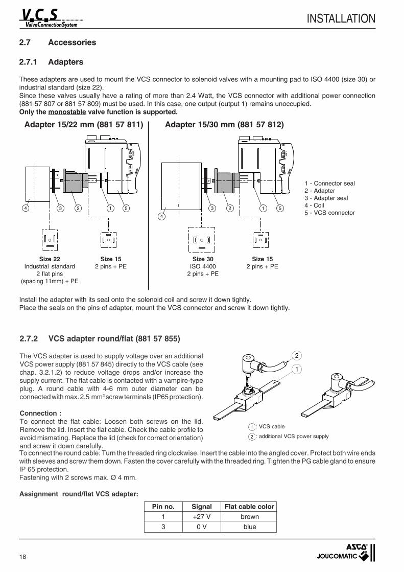
2.7.2 VCS adapter round/flat (881 57 855)
The VCS adapter is used to supply voltage over an additionalVCS power supply (881 57 845) directly to the VCS cable (seechap. 3.2.1.2) to reduce voltage drops and/or increase thesupply current. The flat cable is contacted with a vampire-typeplug. A round cable with 4-6 mm outer diameter can beconnected with max. 2.5 mm2 screw terminals (IP65 protection).
Connection :To connect the flat cable: Loosen both screws on the lid.Remove the lid. Insert the flat cable. Check the cable profile toavoid mismating. Replace the lid (check for correct orientation)and screw it down carefully.
1 - Connector seal2 - Adapter3 - Adapter seal4 - Coil5 - VCS connector
Pin no. Signal Flat cable color1 +27 V brown
3 0 V blue
LIN
K
LIN
K
1234 123
4
5 5
Size 22Industrial standard
2 flat pins(spacing 11mm) + PE
Size 152 pins + PE
Size 30ISO 4400
2 pins + PE
Size 152 pins + PE
2.7 Accessories
2.7.1 Adapters
These adapters are used to mount the VCS connector to solenoid valves with a mounting pad to ISO 4400 (size 30) orindustrial standard (size 22).Since these valves usually have a rating of more than 2.4 Watt, the VCS connector with additional power connection(881 57 807 or 881 57 809) must be used. In this case, one output (output 1) remains unoccupied.Only the monostable valve function is supported.
Adapter 15/22 mm (881 57 811) Adapter 15/30 mm (881 57 812)
1
2
Install the adapter with its seal onto the solenoid coil and screw it down tightly.Place the seals on the pins of adapter, mount the VCS connector and screw it down tightly.
To connect the round cable: Turn the threaded ring clockwise. Insert the cable into the angled cover. Protect both wire endswith sleeves and screw them down. Fasten the cover carefully with the threaded ring. Tighten the PG cable gland to ensureIP 65 protection.Fastening with 2 screws max. Ø 4 mm.
Assignment round/flat VCS adapter:
1 : VCS cable
2 : additional VCS power supply
19
INSTALLATION
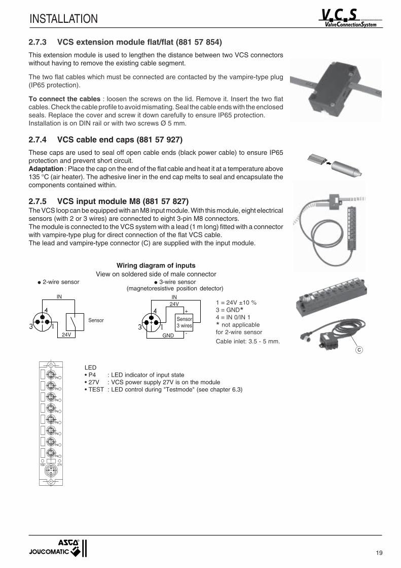
2.7.3 VCS extension module flat/flat (881 57 854)
This extension module is used to lengthen the distance between two VCS connectorswithout having to remove the existing cable segment.
The two flat cables which must be connected are contacted by the vampire-type plug(IP65 protection).
To connect the cables : loosen the screws on the lid. Remove it. Insert the two flatcables. Check the cable profile to avoid mismating. Seal the cable ends with the enclosedseals. Replace the cover and screw it down carefully to ensure IP65 protection.Installation is on DIN rail or with two screws Ø 5 mm.
2.7.4 VCS cable end caps (881 57 927)
These caps are used to seal off open cable ends (black power cable) to ensure IP65protection and prevent short circuit.Adaptation : Place the cap on the end of the flat cable and heat it at a temperature above135 °C (air heater). The adhesive liner in the end cap melts to seal and encapsulate thecomponents contained within.
2.7.5 VCS input module M8 (881 57 827)The VCS loop can be equipped with an M8 input module. With this module, eight electricalsensors (with 2 or 3 wires) are connected to eight 3-pin M8 connectors.The module is connected to the VCS system with a lead (1 m long) fitted with a connectorwith vampire-type plug for direct connection of the flat VCS cable.The lead and vampire-type connector (C) are supplied with the input module.
24VIN
GND
+
-24V
IN
Sensor
1 ≡ 24V ±10 %3 ≡ GND*4 ≡ IN 0/IN 1
* not applicablefor 2-wire sensor
Cable inlet: 3.5 - 5 mm.
Wiring diagram of inputsView on soldered side of male connector
2-wire sensor 3-wire sensor(magnetoresistive position detector)
LED• P4 : LED indicator of input state• 27V : VCS power supply 27V is on the module• TEST : LED control during "Testmode" (see chapter 6.3)
Sensor3 wires
C
20
INSTALLATION
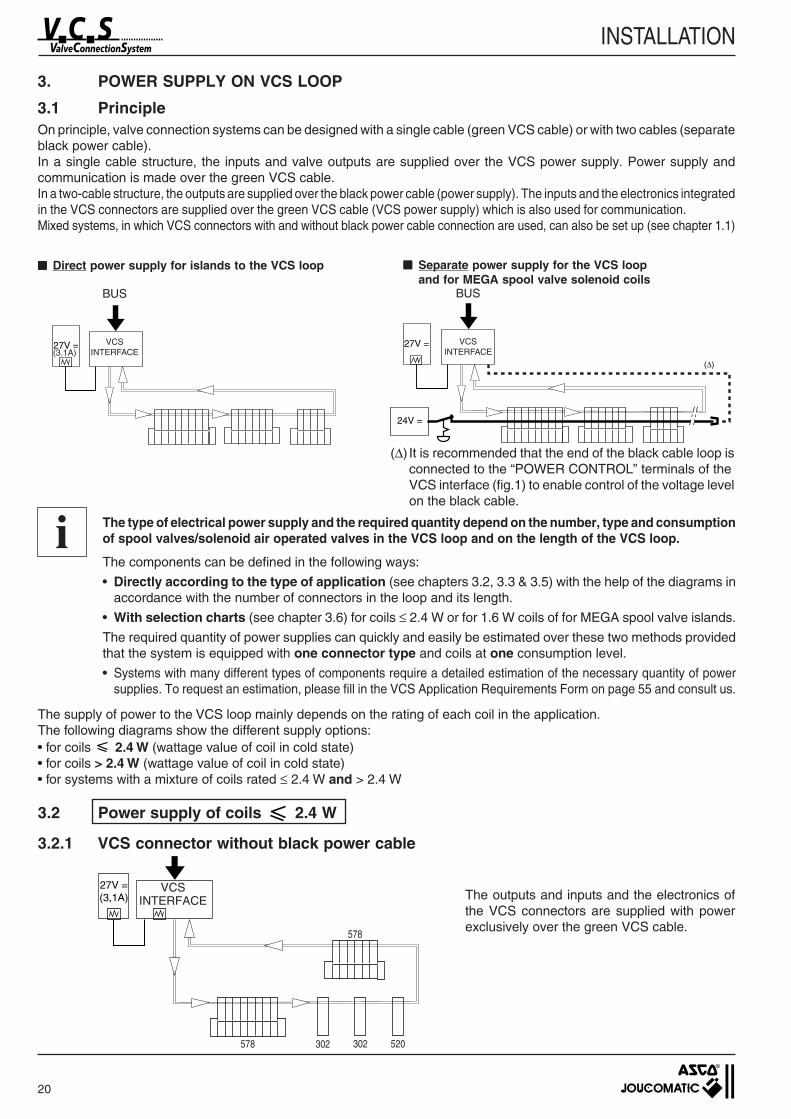
3. POWER SUPPLY ON VCS LOOP
3.1 PrincipleOn principle, valve connection systems can be designed with a single cable (green VCS cable) or with two cables (separateblack power cable).In a single cable structure, the inputs and valve outputs are supplied over the VCS power supply. Power supply andcommunication is made over the green VCS cable.In a two-cable structure, the outputs are supplied over the black power cable (power supply). The inputs and the electronics integratedin the VCS connectors are supplied over the green VCS cable (VCS power supply) which is also used for communication.Mixed systems, in which VCS connectors with and without black power cable connection are used, can also be set up (see chapter 1.1)
Direct power supply for islands to the VCS loop Separate power supply for the VCS loopand for MEGA spool valve solenoid coils
24V =
27V = VCSINTERFACE
BUS
27V =
BUS
VCSINTERFACE
The supply of power to the VCS loop mainly depends on the rating of each coil in the application.The following diagrams show the different supply options:• for coils 2.4 W (wattage value of coil in cold state)• for coils > 2.4 W (wattage value of coil in cold state)• for systems with a mixture of coils rated ≤ 2.4 W and > 2.4 W
The outputs and inputs and the electronics ofthe VCS connectors are supplied with powerexclusively over the green VCS cable.
i The type of electrical power supply and the required quantity depend on the number, type and consumptionof spool valves/solenoid air operated valves in the VCS loop and on the length of the VCS loop.
The components can be defined in the following ways:
• Directly according to the type of application (see chapters 3.2, 3.3 & 3.5) with the help of the diagrams inaccordance with the number of connectors in the loop and its length.
• With selection charts (see chapter 3.6) for coils ≤ 2.4 W or for 1.6 W coils of for MEGA spool valve islands.
The required quantity of power supplies can quickly and easily be estimated over these two methods providedthat the system is equipped with one connector type and coils at one consumption level.
• Systems with many different types of components require a detailed estimation of the necessary quantity of powersupplies. To request an estimation, please fill in the VCS Application Requirements Form on page 55 and consult us.
3.2 Power supply of coils 2.4 W
3.2.1 VCS connector without black power cable
(3.1A)
(∆) It is recommended that the end of the black cable loop isconnected to the “POWER CONTROL” terminals of theVCS interface (fig.1) to enable control of the voltage levelon the black cable.
302 302 520578
578
27V =(3,1A)
VCSINTERFACE
21
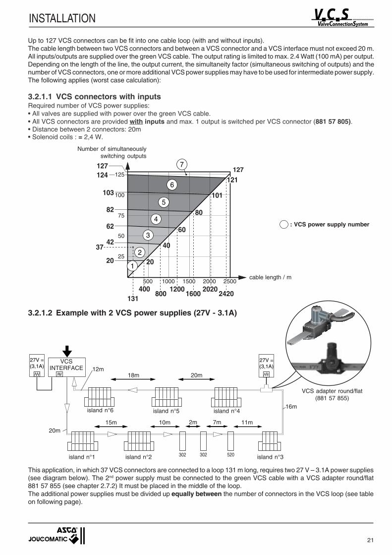
INSTALLATION
Up to 127 VCS connectors can be fit into one cable loop (with and without inputs).The cable length between two VCS connectors and between a VCS connector and a VCS interface must not exceed 20 m.All inputs/outputs are supplied over the green VCS cable. The output rating is limited to max. 2.4 Watt (100 mA) per output.Depending on the length of the line, the output current, the simultaneity factor (simultaneous switching of outputs) and thenumber of VCS connectors, one or more additional VCS power supplies may have to be used for intermediate power supply.The following applies (worst case calculation):
3.2.1.1 VCS connectors with inputsRequired number of VCS power supplies:• All valves are supplied with power over the green VCS cable.• All VCS connectors are provided with inputs and max. 1 output is switched per VCS connector (881 57 805).• Distance between 2 connectors: 20m• Solenoid coils : = 2,4 W.
Number of simultaneouslyswitching outputs
3.2.1.2 Example with 2 VCS power supplies (27V - 3.1A)
This application, in which 37 VCS connectors are connected to a loop 131 m long, requires two 27 V – 3.1A power supplies(see diagram below). The 2nd power supply must be connected to the green VCS cable with a VCS adapter round/flat881 57 855 (see chapter 2.7.2) It must be placed in the middle of the loop.The additional power supplies must be divided up equally between the number of connectors in the VCS loop (see tableon following page).
500 1000 1500 2000 2500
25
50
75
100
125127
400800
12001600
20202420
20
42
62
82
103
124
20
40
60
80
101
121
2
3
4
5
6
7127
37
131
1
cable length / m
: VCS power supply number
VCS adapter round/flat(881 57 855)
island n°6 island n°5 island n°4
302 302 520
27V =(3,1A)
27V =(3,1A)
15m 10m 11m
16m
18m 20m
7m2m
12m
20m
VCSINTERFACE
island n°1 island n°2 island n°3
22
INSTALLATION
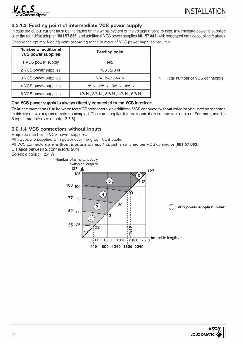
3.2.1.4 VCS connectors without inputsRequired number of VCS power supplies:All valves are supplied with power over the green VCS cable.All VCS connectors are without inputs and max. 1 output is switched per VCS connector (881 57 803).Distance between 2 connectors: 20mSolenoid coils : = 2.4 W.
3.2.1.3 Feeding point of intermediate VCS power supplyIn case the output current must be increased on the whole system or the voltage drop is to high, intermediate power is suppliedover the round/flat adapter (881 57 855) and additional VCS power supplies 881 57 845 (with integrated data decoupling feature).
Choose the optimal feeding point according to the number of VCS power supplies required.
One VCS power supply is always directly connected to the VCS interface.To bridge more than 20 m between two VCS connectors, an additional VCS connector without valve is to be used as repeater.In this case, two outputs remain unoccupied. The same applies if more inputs than outputs are required. For more, use the8 inputs module (see chapter 2.7.5)
cable length / m
Number of additionalVCS power supplies Feeding point
1 VCS power supply N/2
2 VCS power supplies N/3 , 2/3 N
3 VCS power supplies N/4 , N/2 , 3/4 N
4 VCS power supplies 1/5 N , 2/5 N , 3/5 N , 4/5 N
5 VCS power supplies 1/6 N , 2/6 N , 3/6 N , 4/6 N , 5/6 N
N = Total number of VCS connectors
1910
500 1000 1500 2000 2500
25
50
75
100
125127
440 900 1340 1800 2240
22
45
67
90
112
52
77
103
251
2
3
4
56
127
Number of simultaneouslyswitching outputs
: VCS power supply number

23
INSTALLATION
3.2.2 VCS connector with black power cable (two cable structure)
The output current is limited to 100mA per solenoid coil. All valves with a 15 mm pad mounting and max. 2.4 Watt can bedirectly piloted in this manner.To pilot valves with a higher size coil, adapters of 15 mm to 22 mm (industrial standard) and 15 mm to 30 mm (ISO 4400)are available.To realise an emergency shutdown with bistable valves with max. 2.4 Watt, the VCS connector is available with anadditional power connection (black power cable) and two outputs of max. 100 mA.The outputs of the VCS connectors with black power cable connection are supplied over the black power cable. The outputrating is limited to 2.4 Watt (100 mA) per output.Depending on the length of the VCS line, you may have to use either one or several additional VCS power supplies forintermediate power supply.
3.2.2.1 VCS connectors with inputsRequired number of VCS power supplies:• All valves are supplied with power over the black cable.• All VCS connectors are provided with inputs and an additional power connection (881 57 951).• Distance between 2 connectors: 20m• Solenoid coils : = 2.4 W.
Number of simultaneouslyswitching outputs
cable length / m
302 302 520578578
578578
3,1A
27V =(3,1A)
24V =(10A)
10A
This configuration allows for an emergencyswitch to be fitted in order to interrupt thepower supply to the solenoid coils in the loopif necessary. The power supply feeds 10A tothe black cable to supply the coils with power.In case of power failure on the black cable,the VCS interface continues transmittingposition sensor and diagnostic data over thegreen VCS cable.
500 1000 1500 2000 2500
25
50
75
100
125127
351
2
3
4
70
105
1595
700 1400 2100
62
124127
: VCS power supply number
VCSINTERFACE
24
INSTALLATION
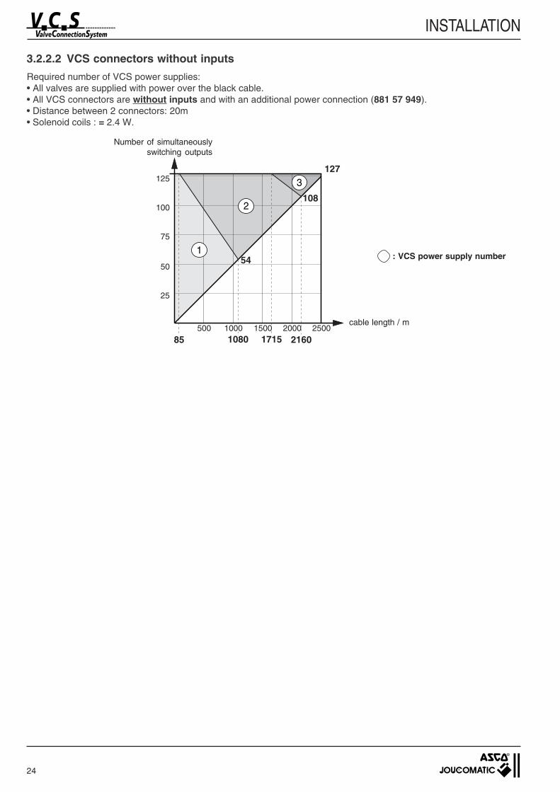
3.2.2.2 VCS connectors without inputs
Required number of VCS power supplies:• All valves are supplied with power over the black cable.• All VCS connectors are without inputs and with an additional power connection (881 57 949).• Distance between 2 connectors: 20m• Solenoid coils : = 2.4 W.
Number of simultaneouslyswitching outputs
cable length / m
: VCS power supply number
500 1000 1500 2000 2500
25
50
75
100
125127
541
2
3
85
108
1080 1715 2160
25
INSTALLATION
24V =(10A)
190
ISO1 (541)
192
ISO4 (544)
320 370 238
27V =(3,1A)
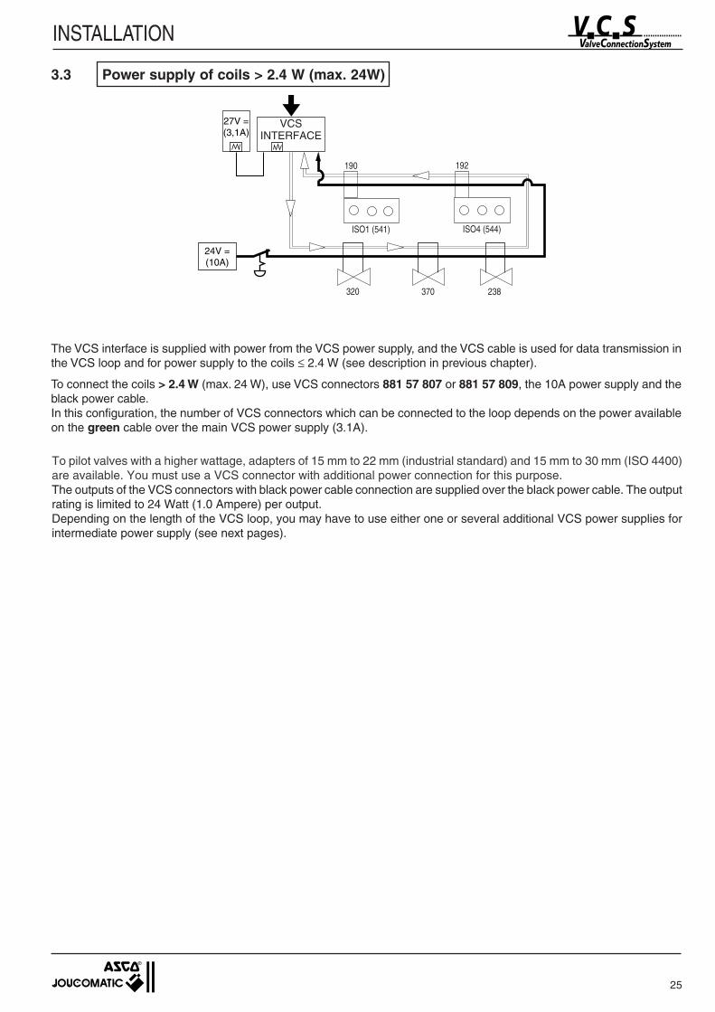
The VCS interface is supplied with power from the VCS power supply, and the VCS cable is used for data transmission inthe VCS loop and for power supply to the coils ≤ 2.4 W (see description in previous chapter).
To connect the coils > 2.4 W (max. 24 W), use VCS connectors 881 57 807 or 881 57 809, the 10A power supply and theblack power cable.In this configuration, the number of VCS connectors which can be connected to the loop depends on the power availableon the green cable over the main VCS power supply (3.1A).
To pilot valves with a higher wattage, adapters of 15 mm to 22 mm (industrial standard) and 15 mm to 30 mm (ISO 4400)are available. You must use a VCS connector with additional power connection for this purpose.The outputs of the VCS connectors with black power cable connection are supplied over the black power cable. The outputrating is limited to 24 Watt (1.0 Ampere) per output.Depending on the length of the VCS loop, you may have to use either one or several additional VCS power supplies forintermediate power supply (see next pages).
3.3 Power supply of coils > 2.4 W (max. 24W)
VCSINTERFACE
26
INSTALLATION
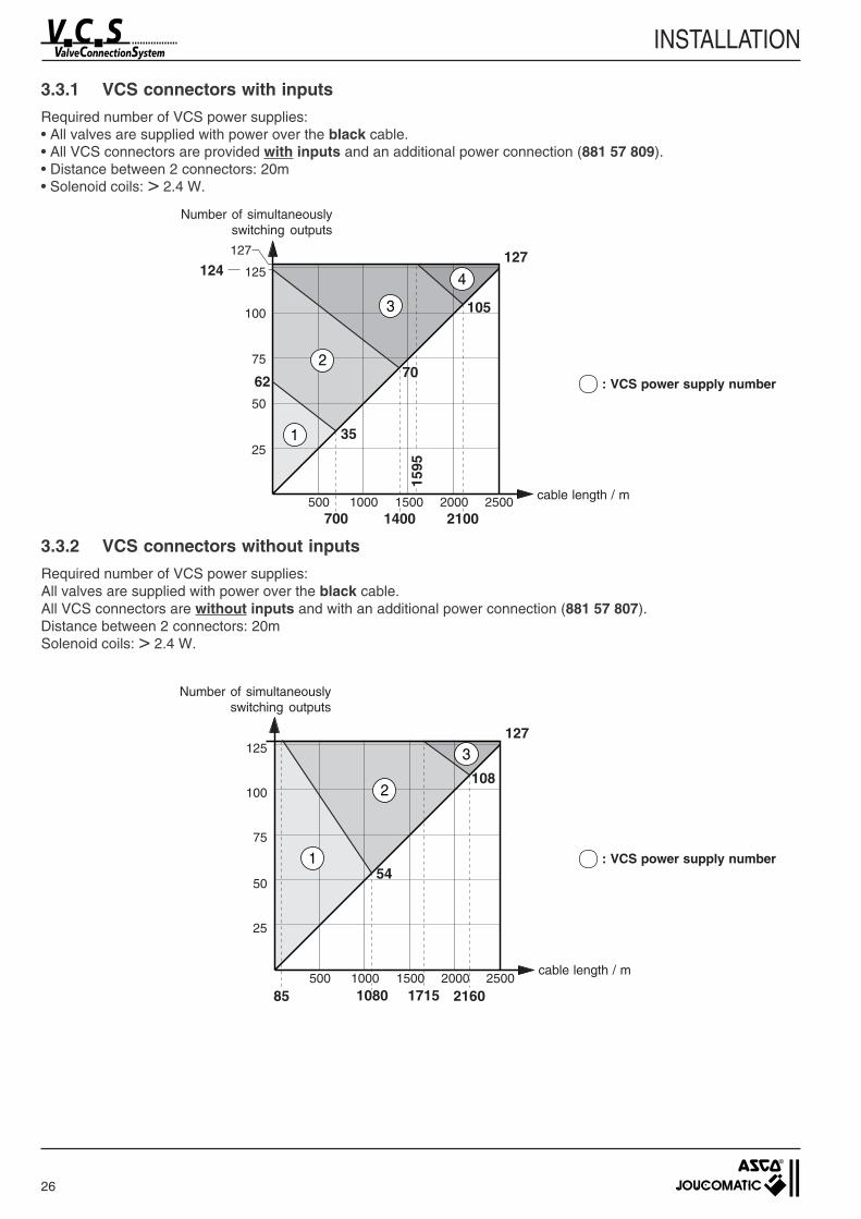
3.3.1 VCS connectors with inputs
Required number of VCS power supplies:• All valves are supplied with power over the black cable.• All VCS connectors are provided with inputs and an additional power connection (881 57 809).• Distance between 2 connectors: 20m• Solenoid coils: > 2.4 W.
Number of simultaneouslyswitching outputs
: VCS power supply number
cable length / m
3.3.2 VCS connectors without inputs
Required number of VCS power supplies:All valves are supplied with power over the black cable.All VCS connectors are without inputs and with an additional power connection (881 57 807).Distance between 2 connectors: 20mSolenoid coils: > 2.4 W.
Number of simultaneouslyswitching outputs
cable length / m
500 1000 1500 2000 2500
25
50
75
100
125127
351
2
3
4
70
105
1595
700 1400 2100
62
124127
500 1000 1500 2000 2500
25
50
75
100
125127
541
2
3
85
108
1080 1715 2160
: VCS power supply number
27
INSTALLATION
24V =(10A)
320 370 238
578578 302 520
370 238
578 302 520
2,4W
2,4W
27V =(3,1A)
Figure 1 Figure 2
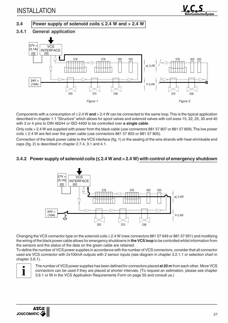
Components with a consumption of ≤ 2.4 W and > 2.4 W can be connected to the same loop. This is the typical applicationdescribed in chapter 1.1 ”Structure” which allows for spool valves and solenoid valves with coil sizes 15, 22, 25, 30 and 40with 3 or 4 pins to DIN 46244 or ISO 4400 to be controlled over a single cable.
Only coils > 2.4 W are supplied with power from the black cable (use connectors 881 57 807 or 881 57 809). The low powercoils ≤ 2.4 W are fed over the green cable (use connectors 881 57 803 or 881 57 805).
Connection of the black power cable to the VCS interface (fig. 1) or the sealing of the wire strands with heat-shrinkable endcaps (fig. 2) is described in chapter 2.7.4, 3.1 and 4.1.
3.4.2 Power supply of solenoid coils (≤≤≤≤≤ 2.4 W and > 2.4 W) with control of emergency shutdown
24V =(10A)
320 370 238
578578 302 520
2,4W
2,4W
27V =(3,1A)
Changing the VCS connector type on the solenoid coils ≤ 2.4 W (new connectors 881 57 949 or 881 57 951) and modifyingthe wiring of the black power cable allows for emergency shutdowns in the VCS loop to be controlled whilst information fromthe sensors and the status of the data on the green cable are retained.To define the number of VCS power supplies in accordance with the number of VCS connectors, consider that all connectorused are VCS connector with 2x100mA outputs with 2 sensor inputs (see diagram in chapter 3.2.1.1 or selection chart inchapter 3.6.1).
The number of VCS power supplies has been defined for connectors placed at 20 m from each other. More VCSconnectors can be used if they are placed at shorter intervals. (To request an estimation, please see chapter3.6.1 or fill in the VCS Application Requirements Form on page 55 and consult us.)
3.4 Power supply of solenoid coils ≤≤≤≤≤ 2.4 W and > 2.4 W
3.4.1 General application
i
VCSINTERFACE
VCSINTERFACE
28
INSTALLATION
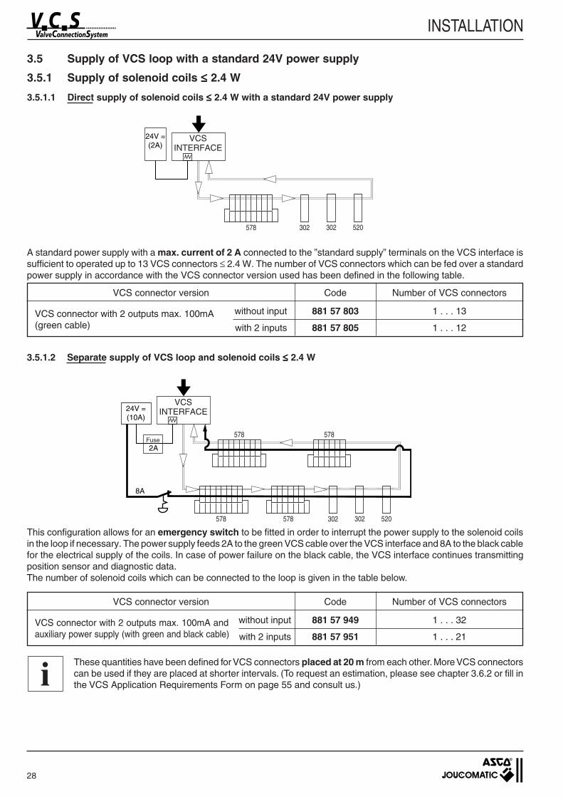
3.5 Supply of VCS loop with a standard 24V power supply
3.5.1 Supply of solenoid coils ≤≤≤≤≤ 2.4 W
3.5.1.1 Direct supply of solenoid coils ≤≤≤≤≤ 2.4 W with a standard 24V power supply
24V =(2A)
302 302 520578
A standard power supply with a max. current of 2 A connected to the ”standard supply” terminals on the VCS interface issufficient to operated up to 13 VCS connectors ≤ 2.4 W. The number of VCS connectors which can be fed over a standardpower supply in accordance with the VCS connector version used has been defined in the following table.
VCS connector version Code Number of VCS connectors
VCS connector with 2 outputs max. 100mA without input 881 57 803 1 . . . 13
(green cable) with 2 inputs 881 57 805 1 . . . 12
3.5.1.2 Separate supply of VCS loop and solenoid coils ≤≤≤≤≤ 2.4 W
302 302 520578578
578578
2A
8A
24V =(10A)
VCS connector version Code Number of VCS connectors
VCS connector with 2 outputs max. 100mA and without input 881 57 949 1 . . . 32
auxiliary power supply (with green and black cable) with 2 inputs 881 57 951 1 . . . 21
This configuration allows for an emergency switch to be fitted in order to interrupt the power supply to the solenoid coilsin the loop if necessary. The power supply feeds 2A to the green VCS cable over the VCS interface and 8A to the black cablefor the electrical supply of the coils. In case of power failure on the black cable, the VCS interface continues transmittingposition sensor and diagnostic data.The number of solenoid coils which can be connected to the loop is given in the table below.
i
Fuse
VCSINTERFACE
VCSINTERFACE
These quantities have been defined for VCS connectors placed at 20 m from each other. More VCS connectorscan be used if they are placed at shorter intervals. (To request an estimation, please see chapter 3.6.2 or fill inthe VCS Application Requirements Form on page 55 and consult us.)
29
INSTALLATION
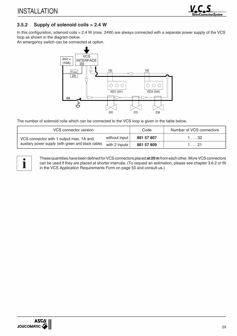
3.5.2 Supply of solenoid coils > 2.4 W
In this configuration, solenoid coils > 2.4 W (max. 24W) are always connected with a separate power supply of the VCSloop as shown in the diagram below.An emergency switch can be connected at option.
2A
8A
24V =(10A)
190
ISO1 (541)
192
ISO4 (544)
320 370 238
The number of solenoid coils which can be connected to the VCS loop is given in the table below.
VCS connector version Code Number of VCS connectors
VCS connector with 1 output max. 1A and without input 881 57 807 1 . . . 32
auxiliary power supply (with green and black cable) with 2 inputs 881 57 809 1 . . . 21
These quantities have been defined for VCS connectors placed at 20 m from each other. More VCS connectorscan be used if they are placed at shorter intervals. (To request an estimation, please see chapter 3.6.2 or fillin the VCS Application Requirements Form on page 55 and consult us.)i
Fuse
VCSINTERFACE
30
INSTALLATION
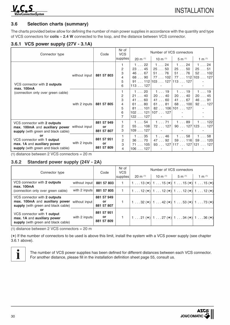
3.6 Selection charts (summary)
The charts provided below allow for defining the number of main power supplies in accordance with the quantity and typeof VCS connectors for coils = 2.4 W connected to the loop, and the distance between VCS connector.
3.6.1 VCS power supply (27V - 3.1A)
(*) If the number of connectors to be used is above this limit, install the system with a VCS power supply (see chapter3.6.1 above).
The number of VCS power supplies has been defined for different distances between each VCS connector.For another distance, please fill in the installation definition sheet page 55, consult us.i
Connector type CodeNr ofVCS
supplies
Connector type CodeNr ofVCS
supplies
Number of VCS connectors
VCS connector with 2 outputsmax. 100mA(connection only over green cable)
without input
with 2 inputs
881 57 803
881 57 805
123456
1 . . . 2223 . . . 4546 . . . 6768 . . . 9091 . . . 112
113 . . . 127
1234567
1 . . . 2021 . . . 4041 . . . 6061 . . . 8081 . . . 101
102 . . . 121122 . . . 127
VCS connector with 2 outputsmax. 100mA and auxiliary powersupply (with green and black cable)
orVCS connector with 1 outputmax. 1A and auxiliary powersupply (with green and black cable)
without input
with 2 inputs
881 57 949or
881 57 807
881 57 951or
881 57 809
123
1 . . . 5455 . . . 108
109 . . . 127
1234
1 . . . 3536 . . . 7071 . . . 105
106 . . . 127
3.6.2 Standard power supply (24V - 2A)
without input
with 2 inputs
881 57 803
881 57 805
1 1 . . . 13 (*)
1 1 . . . 12 (*)
VCS connector with 2 outputsmax. 100mA and auxiliary powersupply (with green and black cable)
orVCS connector with 1 outputmax. 1A and auxiliary powersupply (with green and black cable)
without input
with 2 inputs
881 57 949or
881 57 807
881 57 951or
881 57 809
1 1 . . . 32 (*)
1 1 . . . 21 (*)
VCS connector with 2 outputsmax. 100mA(connection only over green cable)
1 . . . 2425 . . . 5051 . . . 7677 . . . 102
103 . . . 127-
1 . . . 2425 . . . 5051 . . . 7677 . . . 112
113 . . . 127-
1 . . . 2425 . . . 5152 . . . 102
103 . . . 127--
1 . . . 1920 . . . 4041 . . . 6061 . . . 8182 . . . 106
107 . . . 127-
1 . . . 1920 . . . 4041 . . . 6768 . . . 100
101 . . . 127--
1 . . . 1920 . . . 4546 . . . 9192 . . . 127
---
1 . . . 7172 . . . 127
-
1 . . . 4647 . . . 9293 . . . 127
-
1 . . . 8990 . . . 127
-
1 . . . 5859 . . . 116
117 . . . 127-
1 . . . 122123 . . . 127
-
1 . . . 5859 . . . 120
121 . . . 127-
20 m (1) 10 m (1) 5 m (1) 1 m (1)
Number of VCS connectors
20 m (1) 10 m (1) 5 m (1) 1 m (1)
1 . . . 15 (*)
1 . . . 12 (*)
1 . . . 42 (*)
1 . . . 27 (*)
1 . . . 15 (*)
1 . . . 12 (*)
1 . . . 53 (*)
1 . . . 34 (*)
1 . . . 15 (*)
1 . . . 73 (*)
1 . . . 36 (*)
1 . . . 12 (*)
(1) distance between 2 VCS connectors = 20 m
(1) distance between 2 VCS connectors = 20 m
31
INSTALLATION
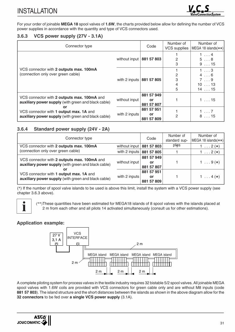
For your order of joinable MEGA 18 spool valves of 1.6W, the charts provided below allow for defining the number of VCSpower supplies in accordance with the quantity and type of VCS connectors used.
3.6.3 VCS power supply (27V - 3.1A)
Connector type CodeNumber of
VCS suppliesNumber of
MEGA 18 islands(**)
VCS connector with 2 outputs max. 100mA(connection only over green cable)
without input
with 2 inputs
881 57 803
881 57 805
123
1 . . . 45 . . . 89 . . . 15
12345
1 . . . 34 . . . 67 . . . 9
10 . . . 1314 . . . 15
VCS connector with 2 outputs max. 100mA andauxiliary power supply (with green and black cable)
orVCS connector with 1 output max. 1A andauxiliary power supply (with green and black cable)
without input
with 2 inputs
881 57 949or
881 57 807881 57 951
or881 57 809
1 1 . . . 15
12
1 . . . 78 . . . 15
3.6.4 Standard power supply (24V - 2A)
Connector type CodeNumber of
standard sup-plies
Number ofMEGA 18 islands(**)
without inputwith 2 inputs
881 57 803881 57 805
1 1 . . . 2 (*)
1 1 . . . 2 (*)
VCS connector with 2 outputs max. 100mA andauxiliary power supply (with green and black cable)
orVCS connector with 1 output max. 1A andauxiliary power supply (with green and black cable)
without input
with 2 inputs
881 57 949or
881 57 807881 57 951
or881 57 809
1 1 . . . 9 (*)
1 1 . . . 4 (*)
VCS connector with 2 outputs max. 100mA(connection only over green cable)
(*) If the number of spool valve islands to be used is above this limit, install the system with a VCS power supply (seechapter 3.6.3 above).
(**)These quantities have been estimated for MEGA18 islands of 8 spool valves with the islands placed at2 m from each other and all pilots 14 activated simultaneously (consult us for other estimations).i
27 V3,1 A
2 m
2 m
2 m 2 m
2 m
Application example:
A complete piloting system for process valves in the textile industry requires 32 bistable 5/2 spool valves. All joinable MEGAspool valves with 1.6W coils are provided with VCS connectors for green cable only and are without M8 inputs (code881 57 803). The island structure and the short distances between the islands as shown in the above diagram allow for the32 connectors to be fed over a single VCS power supply (3.1A).
MEGA island MEGA island MEGA island MEGA island
VCSINTERFACE
32
INSTALLATION
blbrbrbl
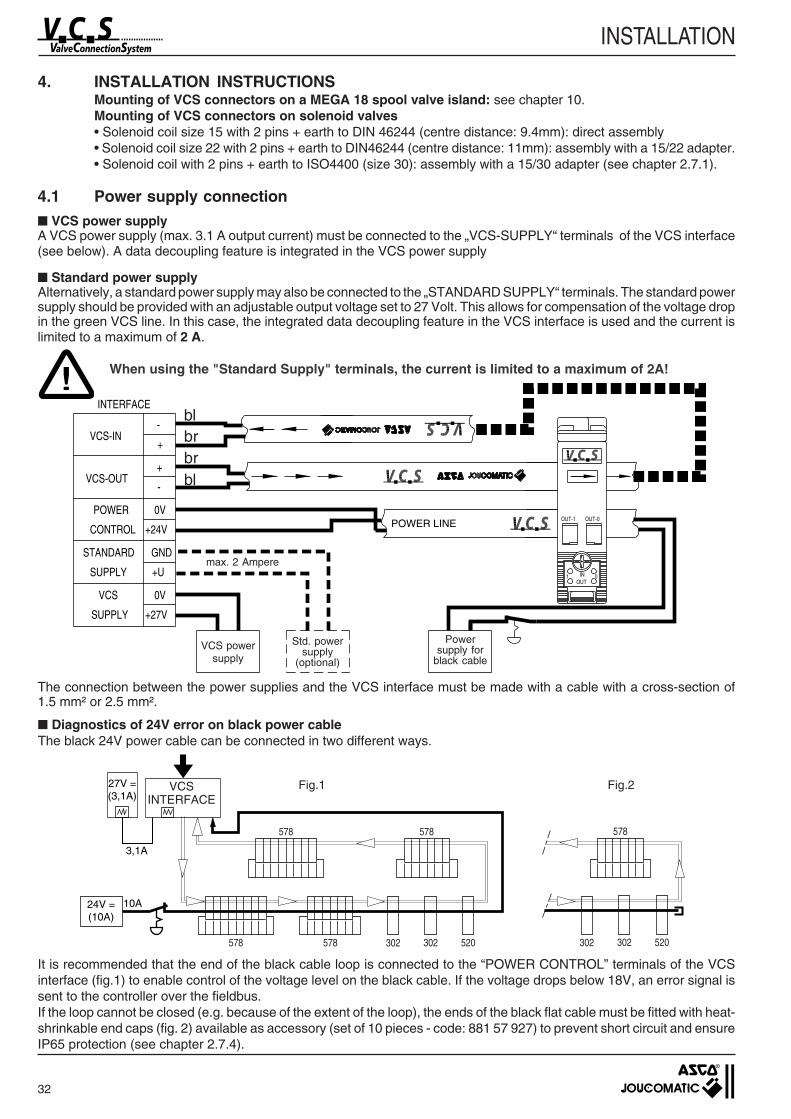
The connection between the power supplies and the VCS interface must be made with a cable with a cross-section of1.5 mm² or 2.5 mm².
Diagnostics of 24V error on black power cableThe black 24V power cable can be connected in two different ways.
4. INSTALLATION INSTRUCTIONSMounting of VCS connectors on a MEGA 18 spool valve island: see chapter 10.Mounting of VCS connectors on solenoid valves• Solenoid coil size 15 with 2 pins + earth to DIN 46244 (centre distance: 9.4mm): direct assembly• Solenoid coil size 22 with 2 pins + earth to DIN46244 (centre distance: 11mm): assembly with a 15/22 adapter.• Solenoid coil with 2 pins + earth to ISO4400 (size 30): assembly with a 15/30 adapter (see chapter 2.7.1).
4.1 Power supply connection VCS power supplyA VCS power supply (max. 3.1 A output current) must be connected to the „VCS-SUPPLY“ terminals of the VCS interface(see below). A data decoupling feature is integrated in the VCS power supply
Standard power supplyAlternatively, a standard power supply may also be connected to the „STANDARD SUPPLY“ terminals. The standard powersupply should be provided with an adjustable output voltage set to 27 Volt. This allows for compensation of the voltage dropin the green VCS line. In this case, the integrated data decoupling feature in the VCS interface is used and the current islimited to a maximum of 2 A.
When using the "Standard Supply" terminals, the current is limited to a maximum of 2A!
max. 2 Ampere
VCS powersupply
Std. powersupply
(optional)
Powersupply for
black cable
!
302 302 520578578
578578
3,1A
302 302 520
578
27V =(3,1A)
24V =(10A)
10A
It is recommended that the end of the black cable loop is connected to the “POWER CONTROL” terminals of the VCSinterface (fig.1) to enable control of the voltage level on the black cable. If the voltage drops below 18V, an error signal issent to the controller over the fieldbus.If the loop cannot be closed (e.g. because of the extent of the loop), the ends of the black flat cable must be fitted with heat-shrinkable end caps (fig. 2) available as accessory (set of 10 pieces - code: 881 57 927) to prevent short circuit and ensureIP65 protection (see chapter 2.7.4).
Fig.1 Fig.2VCSINTERFACE
33
INSTALLATION
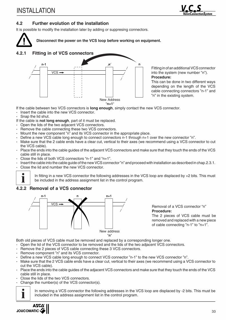
n-1 nn
VCS
If the cable between two VCS connectors is long enough, simply contact the new VCS connector.- Insert the cable into the new VCS connector.- Snap the lid shut.If the cable is not long enough, part of it must be replaced.- Open the lids of the two adjacent VCS connectors.- Remove the cable connecting these two VCS connectors.- Mount the new component ”n” and its VCS connector in the appropriate place.- Define a new VCS cable long enough to connect connectors n-1 through n+1 over the new connector ”n”.- Make sure that the 2 cable ends have a clear cut, vertical to their axes (we recommend using a VCS connector to cut
the VCS cable).- Place the ends into the cable guides of the adjacent VCS connectors and make sure that they touch the ends of the VCS
cable still in place.- Close the lids of both VCS connectors “n-1” and “n+1”.- Insert the cable into the cable guide of the new VCS connector ”n” and proceed with installation as described in chap.2.3.1.- Close the lid and number the new VCS connector.
In fitting in a new VCS connector the following addresses in the VCS loop are displaced by +2 bits. This mustbe included in the address assignment list in the control program.
4.2.2 Removal of a VCS connector
4.2 Further evolution of the installationIt is possible to modify the installation later by adding or suppresing connectors.
Disconnect the power on the VCS loop before working on equipment.
4.2.1 Fitting in of VCS connectors
New Address"n+1"
Fitting in of an additional VCS connectorinto the system (new number ”n”).Procedure:This can be done in two different waysdepending on the length of the VCScable connecting connectors ”n-1” and”n” in the existing system.
!
Both old pieces of VCS cable must be removed and replaced by a corresponding longer one.- Open the lid of the VCS connector to be removed and the lids of the two adjacent VCS connectors.- Remove the 2 pieces of VCS cable connecting these 3 VCS connectors.- Remove component ”n” and its VCS connector.- Define a new VCS cable long enough to connect VCS connector ”n-1” to the new VCS connector ”n”.- Make sure that the 2 VCS cable ends have a clear cut, vertical to their axes (we recommend using a VCS connector to
cut the VCS cable).- Place the ends into the cable guides of the adjacent VCS connectors and make sure that they touch the ends of the VCS
cable still in place.- Close the lids of the two VCS connectors.- Change the number(s) of the VCS connector(s).
In removing a VCS connector the following addresses in the VCS loop are displaced by -2 bits. This must beincluded in the address assignment list in the control program.
n-1 n+1
VCS
n
Removal of a VCS connector “n”Procedure:The 2 pieces of VCS cable must beremoved and replaced with a new pieceof cable connecting ”n-1” to ”n+1”.
i
i
New address"n"
34
INSTALLATION
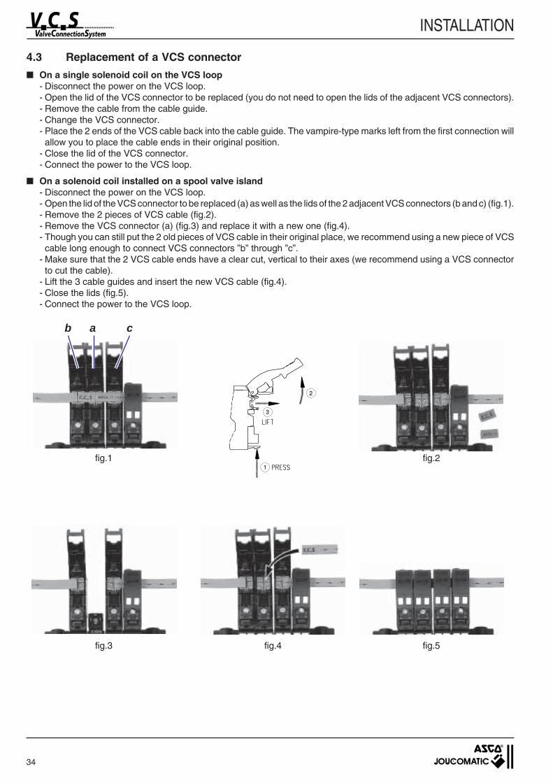
4.3 Replacement of a VCS connector
On a single solenoid coil on the VCS loop- Disconnect the power on the VCS loop.- Open the lid of the VCS connector to be replaced (you do not need to open the lids of the adjacent VCS connectors).- Remove the cable from the cable guide.- Change the VCS connector.- Place the 2 ends of the VCS cable back into the cable guide. The vampire-type marks left from the first connection will
allow you to place the cable ends in their original position.- Close the lid of the VCS connector.- Connect the power to the VCS loop.
On a solenoid coil installed on a spool valve island- Disconnect the power on the VCS loop.- Open the lid of the VCS connector to be replaced (a) as well as the lids of the 2 adjacent VCS connectors (b and c) (fig.1).- Remove the 2 pieces of VCS cable (fig.2).- Remove the VCS connector (a) (fig.3) and replace it with a new one (fig.4).- Though you can still put the 2 old pieces of VCS cable in their original place, we recommend using a new piece of VCS
cable long enough to connect VCS connectors ”b” through ”c”.- Make sure that the 2 VCS cable ends have a clear cut, vertical to their axes (we recommend using a VCS connector
to cut the cable).- Lift the 3 cable guides and insert the new VCS cable (fig.4).- Close the lids (fig.5).- Connect the power to the VCS loop.
b a c
1
3
2
fig.1 fig.2
fig.3 fig.4 fig.5
35
INSTALLATION
5. CONNECTION TO STANDARD FIELDBUS SYSTEM
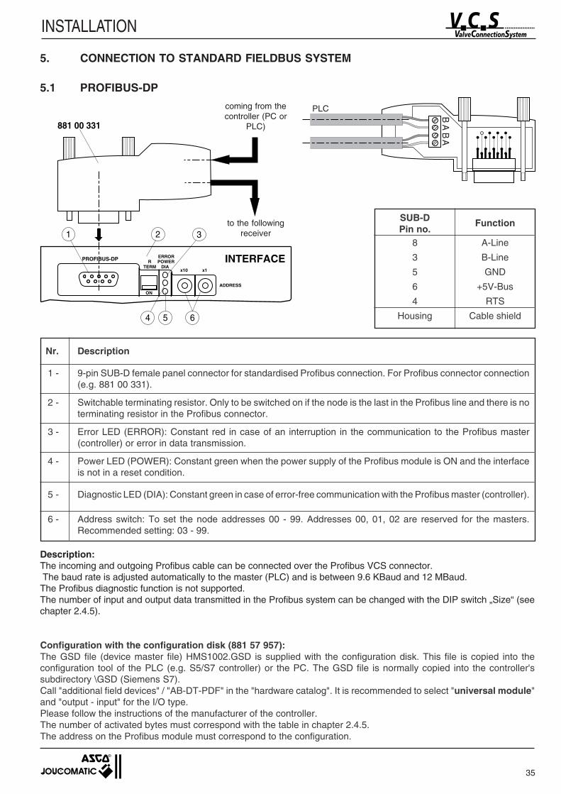
5.1 PROFIBUS-DP
SUB-D FunctionPin no.
8 A-Line
3 B-Line
5 GND
6 +5V-Bus
4 RTS
Housing Cable shield
Nr. Description
1 - 9-pin SUB-D female panel connector for standardised Profibus connection. For Profibus connector connection(e.g. 881 00 331).
2 - Switchable terminating resistor. Only to be switched on if the node is the last in the Profibus line and there is noterminating resistor in the Profibus connector.
3 - Error LED (ERROR): Constant red in case of an interruption in the communication to the Profibus master(controller) or error in data transmission.
4 - Power LED (POWER): Constant green when the power supply of the Profibus module is ON and the interfaceis not in a reset condition.
5 - Diagnostic LED (DIA): Constant green in case of error-free communication with the Profibus master (controller).
6 - Address switch: To set the node addresses 00 - 99. Addresses 00, 01, 02 are reserved for the masters.Recommended setting: 03 - 99.
Description:The incoming and outgoing Profibus cable can be connected over the Profibus VCS connector. The baud rate is adjusted automatically to the master (PLC) and is between 9.6 KBaud and 12 MBaud.The Profibus diagnostic function is not supported.The number of input and output data transmitted in the Profibus system can be changed with the DIP switch „Size“ (seechapter 2.4.5).
Configuration with the configuration disk (881 57 957):The GSD file (device master file) HMS1002.GSD is supplied with the configuration disk. This file is copied into theconfiguration tool of the PLC (e.g. S5/S7 controller) or the PC. The GSD file is normally copied into the controller'ssubdirectory \GSD (Siemens S7).Call "additional field devices" / "AB-DT-PDF" in the "hardware catalog". It is recommended to select "universal module"and "output - input" for the I/O type.Please follow the instructions of the manufacturer of the controller.The number of activated bytes must correspond with the table in chapter 2.4.5.The address on the Profibus module must correspond to the configuration.
PROFIBUS-DPTERM DIA
POWERERROR
R
x10 x1
INTERFACE
ADDRESS
ON
1 2 3
4 5 6
881 00 331B
AB
Acoming from thecontroller (PC or
PLC)
to the followingreceiver
PLC
36
INSTALLATION
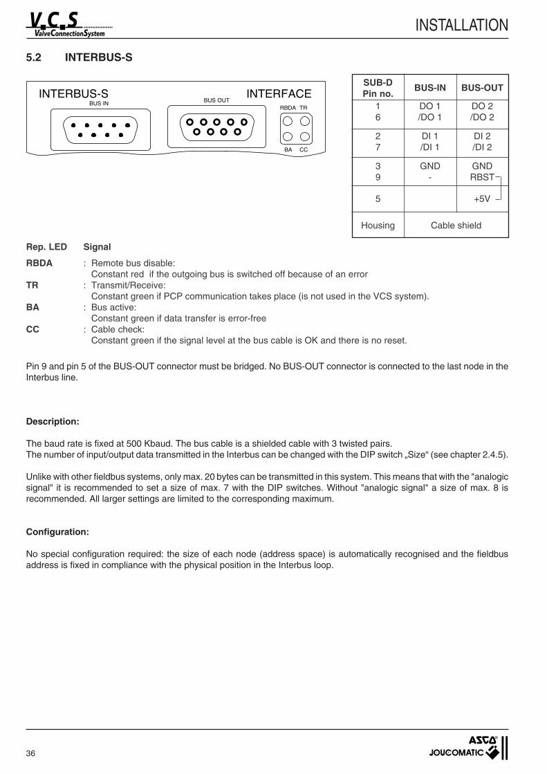
5.2 INTERBUS-S
SUB-D BUS-IN BUS-OUTPin no.
1 DO 1 DO 26 /DO 1 /DO 2
2 DI 1 DI 27 /DI 1 /DI 2
3 GND GND9 - RBST
5 +5V
Housing Cable shield
Pin 9 and pin 5 of the BUS-OUT connector must be bridged. No BUS-OUT connector is connected to the last node in theInterbus line.
Description:
The baud rate is fixed at 500 Kbaud. The bus cable is a shielded cable with 3 twisted pairs.The number of input/output data transmitted in the Interbus can be changed with the DIP switch „Size“ (see chapter 2.4.5).
Unlike with other fieldbus systems, only max. 20 bytes can be transmitted in this system. This means that with the "analogicsignal" it is recommended to set a size of max. 7 with the DIP switches. Without "analogic signal" a size of max. 8 isrecommended. All larger settings are limited to the corresponding maximum.
Configuration:
No special configuration required: the size of each node (address space) is automatically recognised and the fieldbusaddress is fixed in compliance with the physical position in the Interbus loop.
Rep. LED Signal
RBDA : Remote bus disable:Constant red if the outgoing bus is switched off because of an error
TR : Transmit/Receive:Constant green if PCP communication takes place (is not used in the VCS system).
BA : Bus active:Constant green if data transfer is error-free
CC : Cable check:Constant green if the signal level at the bus cable is OK and there is no reset.
37
INSTALLATION
Address (MAC-ID)
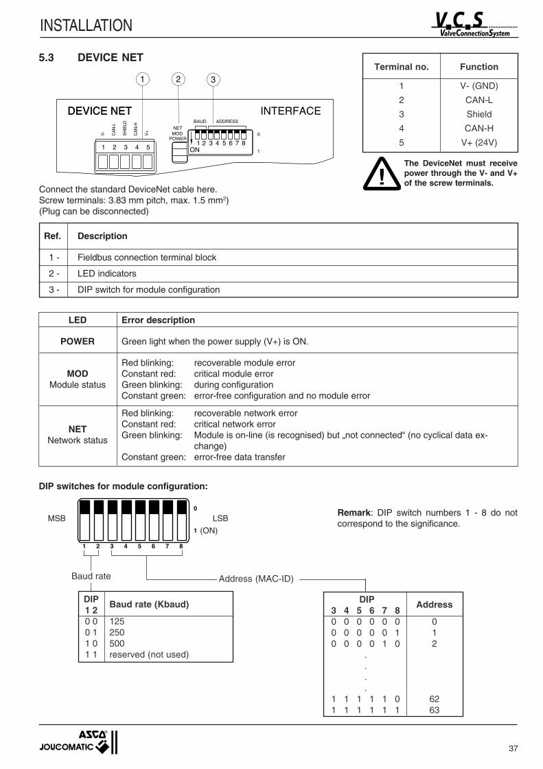
5.3 DEVICE NET
0
1
1 2 43 65 87
MSB LSB
2 31Terminal no. Function
1 V- (GND)
2 CAN-L
3 Shield
4 CAN-H
5 V+ (24V)
Remark: DIP switch numbers 1 - 8 do notcorrespond to the significance.
DIP Baud rate (Kbaud)1 20 0 1250 1 2501 0 5001 1 reserved (not used)
DIP Address3 4 5 6 7 80 0 0 0 0 0 00 0 0 0 0 1 10 0 0 0 1 0 2 . . . .1 1 1 1 1 0 621 1 1 1 1 1 63
Connect the standard DeviceNet cable here.Screw terminals: 3.83 mm pitch, max. 1.5 mm2)(Plug can be disconnected)
Ref. Description
1 - Fieldbus connection terminal block
2 - LED indicators
3 - DIP switch for module configuration
LED Error description
POWER Green light when the power supply (V+) is ON.
Red blinking: recoverable module errorMOD Constant red: critical module error
Module status Green blinking: during configurationConstant green: error-free configuration and no module error
Red blinking: recoverable network error
NET Constant red: critical network error
Network status Green blinking: Module is on-line (is recognised) but „not connected“ (no cyclical data ex-change)
Constant green: error-free data transfer
DIP switches for module configuration:
!The DeviceNet must receivepower through the V- and V+of the screw terminals.
(ON)
Baud rate
38
INSTALLATION
Description:
The DeviceNet cable consists of a twisted pair for data transmission and a twisted pair with a large cross-section for powersupply.A transmission speed of either 125, 250 or 500 Kbaud can be selected.The maximum length of the network is limited in accordance with the baud rate.Data transmission occurs as „Group 2 only server“ and the preset protocol is „master/slave connection set“ for „polled I/O“.External terminating resistors (121 Ohm) must be fitted to both ends of the DeviceNet line. The number of input/output datatransmitted in the DeviceNet can be changed with the DIP switch “Size” (see chapter 2.4.5).
Configuration with the configuration disk (881 57 957):
An EDS file (electronic data sheet), dt1.eds is supplied on the configuration disk. This file is used in the configuration toolof DeviceNet to include the VCS system.Please follow the instructions of the controller manufacturer.
Addressing :The physical addressing of the data exchanged ("size" Dip switches on VCS interface) must be the same as theconfiguration of data exchanged into the configuration software (DeviceNet manager or RSNetWorx). Otherwise the VCSinterface won't communicate with the PLC.
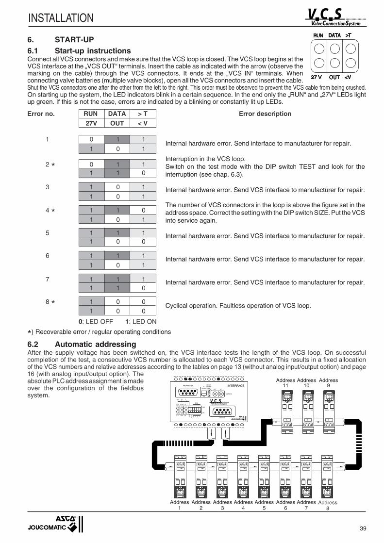
39
INSTALLATION
Error description
Internal hardware error. Send interface to manufacturer for repair.
Interruption in the VCS loop.Switch on the test mode with the DIP switch TEST and look for theinterruption (see chap. 6.3).
Internal hardware error. Send VCS interface to manufacturer for repair.
The number of VCS connectors in the loop is above the figure set in theaddress space. Correct the setting with the DIP switch SIZE. Put the VCSinto service again.
Internal hardware error. Send VCS interface to manufacturer for repair.
Internal hardware error. Send VCS interface to manufacturer for repair.
Internal hardware error. Send VCS interface to manufacturer for repair.
Cyclical operation. Faultless operation of VCS loop.
*) Recoverable error / regular operating conditions
6. START-UP6.1 Start-up instructionsConnect all VCS connectors and make sure that the VCS loop is closed. The VCS loop begins at theVCS interface at the „VCS OUT“ terminals. Insert the cable as indicated with the arrow (observe themarking on the cable) through the VCS connectors. It ends at the „VCS IN“ terminals. Whenconnecting valve batteries (multiple valve blocks), open all the VCS connectors and insert the cable.Shut the VCS connectors one after the other from the left to the right. This order must be observed to prevent the VCS cable from being crushed.On starting up the system, the LED indicators blink in a certain sequence. In the end only the „RUN“ and „27V“ LEDs lightup green. If this is not the case, errors are indicated by a blinking or constantly lit up LEDs.
Error no. RUN DATA > T27V OUT < V
1 0 1 1
1 0 1
2 * 0 1 11 1 0
3 1 0 1
1 0 1
4 * 1 1 0
1 0 1
5 1 1 11 0 0
6 1 1 1
1 0 1
7 1 1 11 1 0
8 * 1 0 0
1 0 0
0: LED OFF 1: LED ON
6.2 Automatic addressingAfter the supply voltage has been switched on, the VCS interface tests the length of the VCS loop. On successfulcompletion of the test, a consecutive VCS number is allocated to each VCS connector. This results in a fixed allocationof the VCS numbers and relative addresses according to the tables on page 13 (without analog input/output option) and page16 (with analog input/output option). Theabsolute PLC address assignment is madeover the configuration of the fieldbussystem.
Address11
Address10
Address9
Address1
Address2
Address3
Address4
Address5
Address6
Address7
Address8
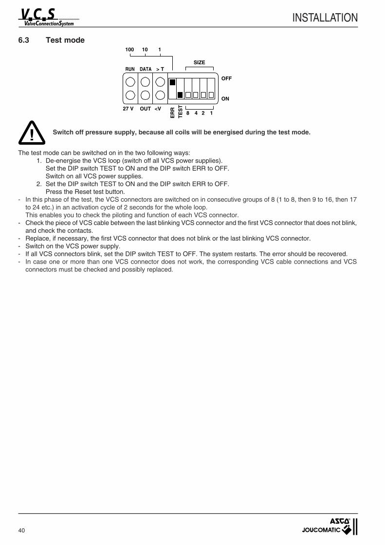
40
INSTALLATION
6.3 Test mode
Switch off pressure supply, because all coils will be energised during the test mode.
The test mode can be switched on in the two following ways:1. De-energise the VCS loop (switch off all VCS power supplies).
Set the DIP switch TEST to ON and the DIP switch ERR to OFF.Switch on all VCS power supplies.
2. Set the DIP switch TEST to ON and the DIP switch ERR to OFF.Press the Reset test button.
- In this phase of the test, the VCS connectors are switched on in consecutive groups of 8 (1 to 8, then 9 to 16, then 17to 24 etc.) in an activation cycle of 2 seconds for the whole loop.This enables you to check the piloting and function of each VCS connector.
- Check the piece of VCS cable between the last blinking VCS connector and the first VCS connector that does not blink,and check the contacts.
- Replace, if necessary, the first VCS connector that does not blink or the last blinking VCS connector.- Switch on the VCS power supply.- If all VCS connectors blink, set the DIP switch TEST to OFF. The system restarts. The error should be recovered.- In case one or more than one VCS connector does not work, the corresponding VCS cable connections and VCS
connectors must be checked and possibly replaced.
100 10 1
SIZE
OFF
ON
27 V
ER
ROUT <V48 12
RUN DATA > T
TE
ST
!
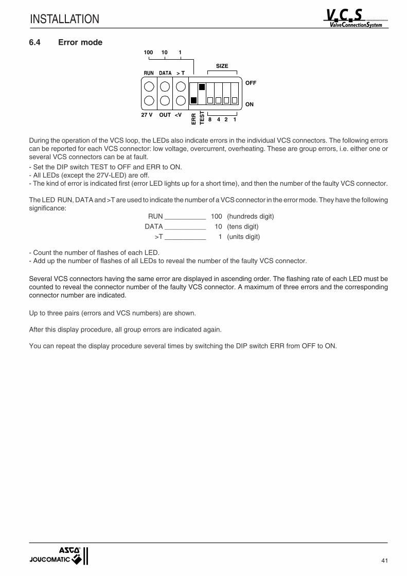
41
INSTALLATION
6.4 Error mode100 10 1
SIZE
OFF
ON
27 V
ER
ROUT <V48 12
RUN DATA > T
TE
ST
During the operation of the VCS loop, the LEDs also indicate errors in the individual VCS connectors. The following errorscan be reported for each VCS connector: low voltage, overcurrent, overheating. These are group errors, i.e. either one orseveral VCS connectors can be at fault.
- Set the DIP switch TEST to OFF and ERR to ON.- All LEDs (except the 27V-LED) are off.- The kind of error is indicated first (error LED lights up for a short time), and then the number of the faulty VCS connector.
The LED RUN, DATA and >T are used to indicate the number of a VCS connector in the error mode. They have the followingsignificance:
RUN ___________ 100 (hundreds digit)
DATA ___________ 10 (tens digit)
>T ___________ 1 (units digit)
- Count the number of flashes of each LED.- Add up the number of flashes of all LEDs to reveal the number of the faulty VCS connector.
Several VCS connectors having the same error are displayed in ascending order. The flashing rate of each LED must becounted to reveal the connector number of the faulty VCS connector. A maximum of three errors and the correspondingconnector number are indicated.
Up to three pairs (errors and VCS numbers) are shown.
After this display procedure, all group errors are indicated again.
You can repeat the display procedure several times by switching the DIP switch ERR from OFF to ON.

42
INSTALLATION
7. PC DIAGNOSTIC SOFTWARE (VCS - DIAG)
7.1 Program installation
Insert the disk „VCS-DIAG“ (881 57 852) into your disk drive. Open the fileREADME.TXT with a text editor and follow the installation instructions given in this file.After successful installation: Change to the directory C:\VCS and executeVCS DIAG.EXE.
Minimum configuration:PC: Pentium IIMemory: 32 MByteFree disk space: 10 MByteOperating system: Windows 95 or higher, Windows NT 4.0
7.2 Connection of the VCS interface
The online functions of VCS-DIAG can only be used if the VCS interface is connected to the PC with the RS-232 cable(881 57 853). Plug one side of the cable into the „RS-232C“ socket of the VCS interface and the other side of the cable intothe serial interface (COM 1 ... COM 2) of your PC.Supply the VCS interface with voltage.
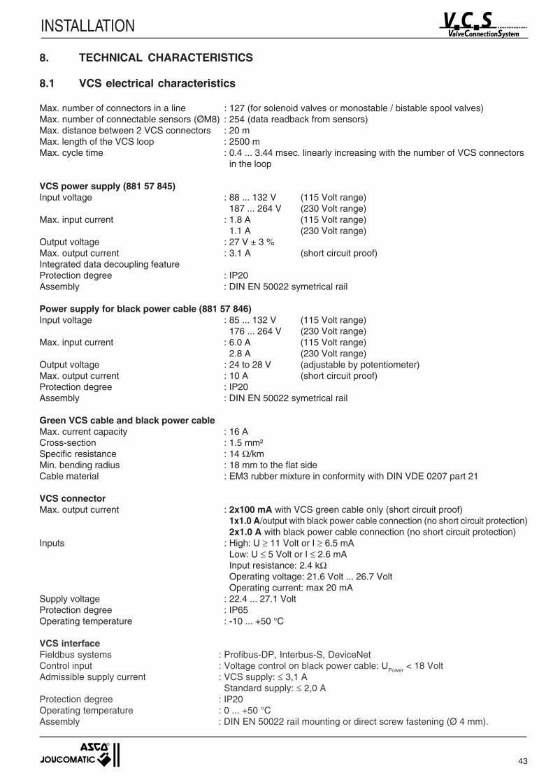
43
INSTALLATION
8. TECHNICAL CHARACTERISTICS
8.1 VCS electrical characteristics
Max. number of connectors in a line : 127 (for solenoid valves or monostable / bistable spool valves)Max. number of connectable sensors (ØM8) : 254 (data readback from sensors)Max. distance between 2 VCS connectors : 20 mMax. length of the VCS loop : 2500 mMax. cycle time : 0.4 ... 3.44 msec. linearly increasing with the number of VCS connectors
in the loop
VCS power supply (881 57 845)Input voltage : 88 ... 132 V (115 Volt range)
187 ... 264 V (230 Volt range)Max. input current : 1.8 A (115 Volt range)
1.1 A (230 Volt range)Output voltage : 27 V ± 3 %Max. output current : 3.1 A (short circuit proof)Integrated data decoupling featureProtection degree : IP20Assembly : DIN EN 50022 symetrical rail
Power supply for black power cable (881 57 846)Input voltage : 85 ... 132 V (115 Volt range)
176 ... 264 V (230 Volt range)Max. input current : 6.0 A (115 Volt range)
2.8 A (230 Volt range)Output voltage : 24 to 28 V (adjustable by potentiometer)Max. output current : 10 A (short circuit proof)Protection degree : IP20Assembly : DIN EN 50022 symetrical rail
Green VCS cable and black power cableMax. current capacity : 16 ACross-section : 1.5 mm²Specific resistance : 14 Ω/kmMin. bending radius : 18 mm to the flat sideCable material : EM3 rubber mixture in conformity with DIN VDE 0207 part 21
VCS connectorMax. output current : 2x100 mA with VCS green cable only (short circuit proof)
1x1.0 A/output with black power cable connection (no short circuit protection)2x1.0 A with black power cable connection (no short circuit protection)
Inputs : High: U ≥ 11 Volt or I ≥ 6.5 mALow: U ≤ 5 Volt or I ≤ 2.6 mAInput resistance: 2.4 kΩOperating voltage: 21.6 Volt ... 26.7 VoltOperating current: max 20 mA
Supply voltage : 22.4 ... 27.1 VoltProtection degree : IP65Operating temperature : -10 ... +50 °C
VCS interfaceFieldbus systems : Profibus-DP, Interbus-S, DeviceNetControl input : Voltage control on black power cable: UPower < 18 VoltAdmissible supply current : VCS supply: ≤ 3,1 A
Standard supply: ≤ 2,0 AProtection degree : IP20Operating temperature : 0 ... +50 °CAssembly : DIN EN 50022 rail mounting or direct screw fastening (Ø 4 mm).
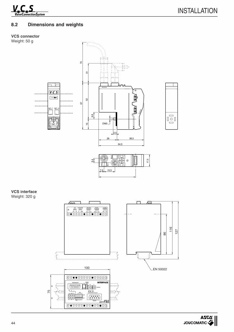
44
INSTALLATION
8.2 Dimensions and weights
IN
24V
POWERCONTROL
27V 0V +U GND
STANDARDVCSSUPPLY SUPPLY
_
blue brown+
bluebrown
VCS OUT VCS IN
0V_+
INTERFACEINTERFACE
100 10 1
SIZE
OFF
ON
27 V
ER
ROUT <V
TEST
48 12
ValveConnectionSystem
PROFIBUS-DPTERM DIA
POWERERROR
R
x10 x1
ADDRESS
ON
RS232C
116
127
EN 50022100
75=
=
86
VCS connectorWeight: 50 g
VCS interfaceWeight: 320 g
Ø
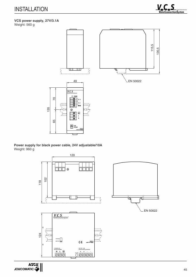
45
INSTALLATION
ValveConnectionSystem
115,
5
130,
5
135
49 EN 50022
7065
24V DC / 10AElectronically protected
+ + _ _24-28V
115/230V AC8.0/2.8A 50/60Hz
N L
115V AC
230V AC
ValveConnectionSystem
EN 50022
124
==
118
120
102
VCS power supply, 27V/3.1AWeight: 560 g
Power supply for black power cable, 24V adjustable/10AWeight: 960 g
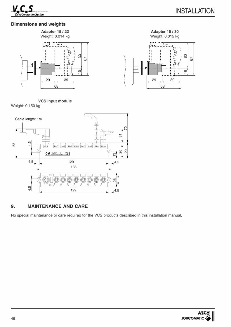
9. MAINTENANCE AND CARE
No special maintenance or care required for the VCS products described in this installation manual.
46
INSTALLATION
Dimensions and weights
Adapter 15 / 22 Adapter 15 / 30Weight: 0.014 kg Weight: 0.015 kg
VCS input moduleWeight: 0.150 kg
4,5
4,5
ValveConnectionSystem
VCS IN-7 IN-6 IN-5 IN-4 IN-3 IN-2 IN-1 IN-0
70
31
2926
1326
138
129
4,5
4,5
55
1294,5
==
Cable length: 1m
LIN
K
52
67
15
68
3929
LIN
K
52
67
15
68
3929
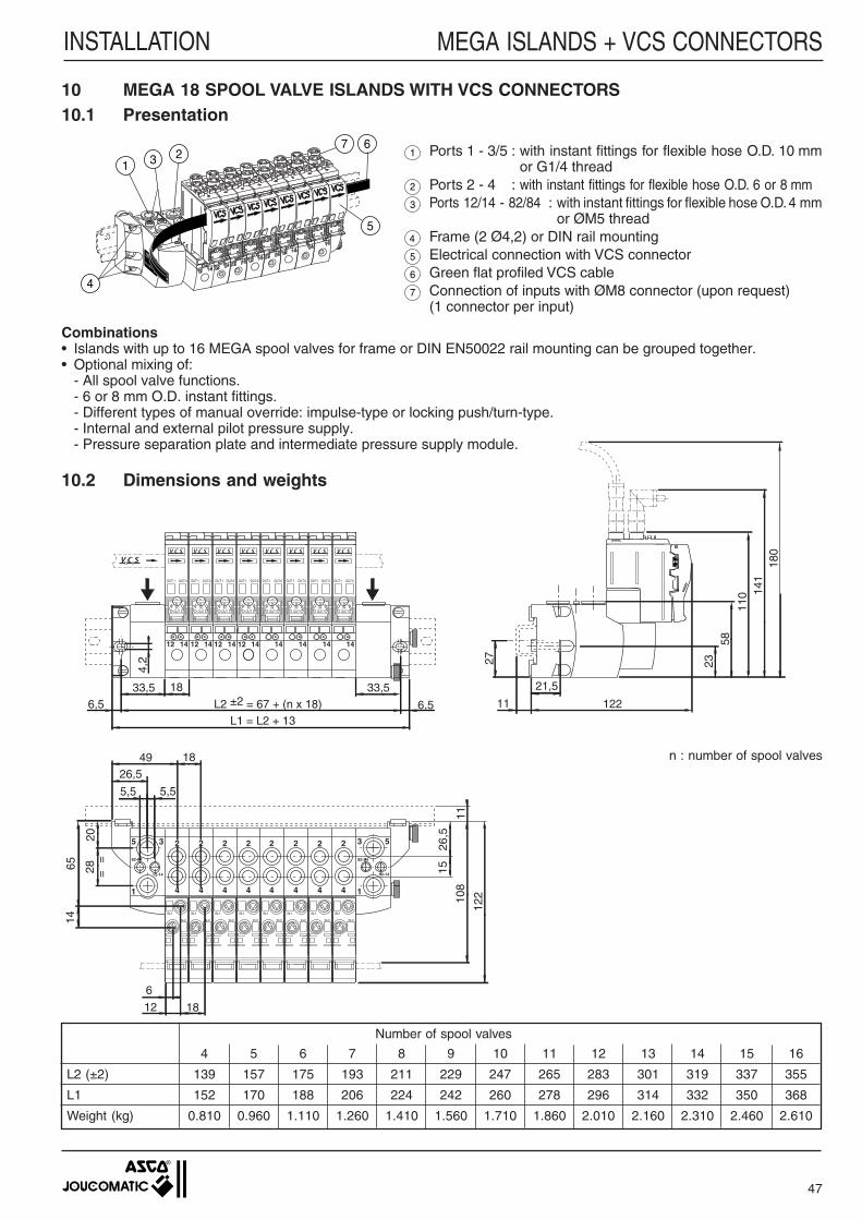
Number of spool valves
4 5 6 7 8 9 10 11 12 13 14 15 16
L2 (±2) 139 157 175 193 211 229 247 265 283 301 319 337 355
L1 152 170 188 206 224 242 260 278 296 314 332 350 368
Weight (kg) 0.810 0.960 1.110 1.260 1.410 1.560 1.710 1.860 2.010 2.160 2.310 2.460 2.610
47
INSTALLATION MEGA ISLANDS + VCS CONNECTORS
123
5
4
7 61 Ports 1 - 3/5 : with instant fittings for flexible hose O.D. 10 mm
or G1/4 thread2 Ports 2 - 4 : with instant fittings for flexible hose O.D. 6 or 8 mm3 Ports 12/14 - 82/84 : with instant fittings for flexible hose O.D. 4 mm
or ØM5 thread4 Frame (2 Ø4,2) or DIN rail mounting5 Electrical connection with VCS connector6 Green flat profiled VCS cable7 Connection of inputs with ØM8 connector (upon request)
(1 connector per input)
10 MEGA 18 SPOOL VALVE ISLANDS WITH VCS CONNECTORS10.1 Presentation
IN-1
IN-0
IN-1
IN-0
IN-1
IN-0
IN-1
IN-0
IN-1
IN-0
IN-1
IN-0
IN-1
IN-0
IN-1
IN-0
INOUT
INOUT
INOUT
INOUT
INOUT
INOUT
INOUT
INOUT
OUT-1 OUT-1 OUT-1 OUT-1OUT-0 OUT-0 OUT-0 OUT-0 OUT-1 OUT-1 OUT-1 OUT-1OUT-0 OUT-0 OUT-0 OUT-0
12
33,5 18
L2 ±2 = 67 + (n x 18)L1 = L2 + 13
33,5
4,2
12 14 12 14 12 14 14 14 14 14 14
6,56,5
184926,5
5,5
2028
26,5
15
108
5 3
1
2
4
2
4
2
4
2
4
2
4
2
4
2
4
2
4
3 5
1
82-84
12-14
82-84
12-14
5,5
11
==
6514
18
6
12
122
11
21,5
27 2358
141
180
122
110
10.2 Dimensions and weights
Combinations• Islands with up to 16 MEGA spool valves for frame or DIN EN50022 rail mounting can be grouped together.• Optional mixing of:
- All spool valve functions.- 6 or 8 mm O.D. instant fittings.- Different types of manual override: impulse-type or locking push/turn-type.- Internal and external pilot pressure supply.- Pressure separation plate and intermediate pressure supply module.
n : number of spool valves
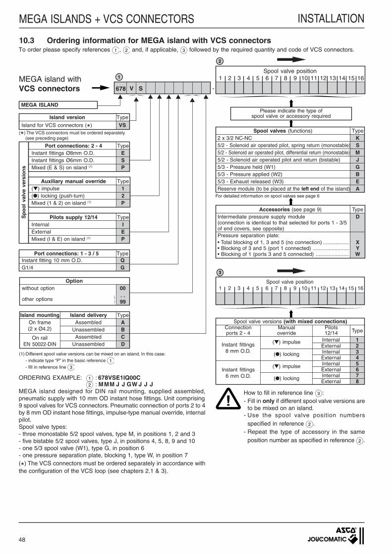
ORDERING EXAMPLE: 1 : 678VSE1IQ00C2 : MMM J J GW J J J
MEGA island designed for DIN rail mounting, supplied assembled,pneumatic supply with 10 mm OD instant hose fittings. Unit comprising9 spool valves for VCS connectors. Pneumatic connection of ports 2 to 4by 8 mm OD instant hose fittings, impulse-type manual override, internalpilot.Spool valve types:- three monostable 5/2 spool valves, type M, in positions 1, 2 and 3- five bistable 5/2 spool valves, type J, in positions 4, 5, 8, 9 and 10- one 5/3 spool valve (W1), type G, in position 6- one pressure separation plate, blocking 1, type W, in position 7(*) The VCS connectors must be ordered separately in accordance withthe configuration of the VCS loop (see chapters 2.1 & 3).
Island version Type
Island for VCS connectors (*) VS
!
3
2
1Spool valve position
1 2 3 4 5 6 7 8 9 10 11 12 13 14 15 16
Please indicate the type ofspool valve or accessory required
-
MEGA island withVCS connectors
MEGA ISLAND
Port connections: 1 - 3 / 5 TypeInstant fitting 10 mm O.D. QG1/4 G
Optionwithout option 00
other options. .99
On frame(2 x Ø4.2)
On railEN 50022-DIN
Assembled AUnassembled B
Assembled CUnassembled D
For detailed information on spool valves see page 6
Island mounting Island delivery Type
10.3 Ordering information for MEGA island with VCS connectors
V
To order please specify references 1 , 2 and, if applicable, 3 followed by the required quantity and code of VCS connectors.
S
Sp
oo
l va
lve
vers
ion
s
Port connections: 2 - 4 TypeInstant fittings Ø8mm O.D. EInstant fittings Ø6mm O.D. SMixed (E & S) on island (1) P
Auxiliary manual override Type() impulse 1() locking (push-turn) 2Mixed (1 & 2) on island (1) P
Pilots supply 12/14 TypeInternal IExternal EMixed (I & E) on island (1) P
Spool valve position1 2 3 4 5 6 7 8 9 10 11 12 13 14 15 16
Spool valves (functions) Type2 x 3/2 NC-NC K5/2 - Solenoid air operated pilot, spring return (monostable) S5/2 - Solenoid air operated pilot, differential return (monostable) M5/2 - Solenoid air operated pilot and return (bistable) J5/3 - Pressure held (W1) G5/3 - Pressure applied (W2) B5/3 - Exhaust released (W3) EReserve module (to be placed at the left end of the island) A
Internal 1External 2Internal 3External 4Internal 5External 6Internal 7External 8
Spool valve versions (with mixed connections)
TypeConnectionports 2 - 4
Manualoverride
Pilots12/14
() impulse
() locking
() impulse
() locking
Instant fittings8 mm O.D.
Instant fittings6 mm O.D.
Accessories (see page 9) TypeIntermediate pressure supply module D(connection is identical to that selected for ports 1 - 3/5of end covers, see opposite)Pressure separation plate:• Total blocking of 1, 3 and 5 (no connection) .................. X• Blocking of 3 and 5 (port 1 connected) ......................... Y• Blocking of 1 (ports 3 and 5 connected) ....................... W
678
How to fill in reference line 3 :- Fill in only if different spool valve versions are
to be mixed on an island.- Use the spool valve position numbers
specified in reference 2 .- Repeat the type of accessory in the same
position number as specified in reference 2 .
(1) Different spool valve versions can be mixed on an island. In this case:- indicate type “P” in the basic reference 1- fill in reference line 3
(*) The VCS connectors must be ordered separately(see preceding page)
48
INSTALLATIONMEGA ISLANDS + VCS CONNECTORS

49
INSTALLATION
L1
10.4 Accessories10.4.1 End covers
The end covers assure the following functions:- Island assembly: the bolts are fixed into the covers. The island is
tightened by hand with the knurled screws (S). There is no need fortools.
- Choice of island mounting:• on machine frame (2 Ø 4.2),• on DIN EN 50022 rail (for cabinet installation).
- Pneumatic connection of the channelled ports of the island(1 – 3/5 – 12/14 etc.)
Island assembly (see chapter 10.7)
Choice of island mountingOn machine frame On DIN EN 50022 rail
Pneumatic connection
3/5112/14 82/84
3/5
1
12/14
82/84
3 5
1
3 5
1
82/84 3/5
1
12/14
Port 1 : Pressure supply for islandPort 3/5 : Exhausts 3 and 5 channelled and connectablePort 12/14 : External pilot pressure supply. Necessary for use with
vacuum or if the general supply pressure is below3 bar.
Port 82/84 : Channelling and connection of the pilot exhausts forinstallation of the island in protected environments(food-processing industries, laboratories etc.)
Port nos.
1
3/5
12/14
82/84
Instant fittings forflexible hoseØ 10mm O.D.
Instant fittings forflexible hoseØ 4mm O.D.
Type: Q Type: G
Connection size
G1/4
M5
2 ØM4
Order codes for end coversDescription Port connections 1 - 3/5 (*) CodeType
1 set of 2 end covers forislands for framemounting
1 set of 2 end covers forislands for DIN railmounting
Instant fittings for 10mm O.D. hose Q 881 57 901
G1/4 thread G 881 57 903
Instant fittings for 10mm O.D. hose Q 881 57 859
G1/4 thread G 881 57 861
(*) For port connections 12/14 and 82/84 see above table
Ø10G1/4
Possibility of direct connection of asilencer to each exhaust 3/5
MEGA ISLANDS + VCS CONNECTORS
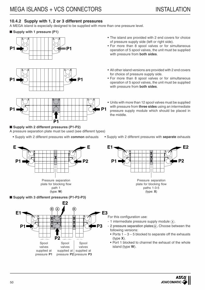
50
P2
E
P1
E3
1
5 3
1
5
P2
E2
P1
E13
1
5 3
1
5
P3
E3
P1
E1
P2
E2A
3
1
B B
5 3
1
5 3
1
5
P1P1
3
1
5 3
1
5
P1P1
P1
3
1
5 3
1
5 3
1
5
10.4.2 Supply with 1, 2 or 3 different pressuresA MEGA island is especially designed to be supplied with more than one pressure level.
Supply with 1 pressure (P1)
• The island are provided with 2 end covers for choiceof pressure supply side (left or right side).
• For more than 8 spool valves or for simultaneousoperation of 5 spool valves, the unit must be suppliedwith pressure from both sides.
• All other island versions are provided with 2 end coversfor choice of pressure supply side.
• For more than 8 spool valves or for simultaneousoperation of 5 spool valves, the unit must be suppliedwith pressure from both sides.
• Units with more than 12 spool valves must be suppliedwith pressure from three sides using an intermediatepressure supply module which should be placed inthe middle.
Supply with 2 different pressures (P1-P2)A pressure separation plate must be used (see different types)
• Supply with 2 different pressures with common exhausts • Supply with 2 different pressures with separate exhausts
Supply with 3 different pressures (P1-P2-P3)
For this configuration use:- 1 intermediate pressure supply module A .- 2 pressure separation plates B . Choose between the
following versions:• Ports 1 – 3 – 5 blocked to separate off the exhausts
(type X).• Port 1 blocked to channel the exhaust of the whole
island (type W).Spoolvalves
supplied atpressure P1
Spoolvalves
supplied atpressure P2
Spoolvalves
supplied atpressure P3
Pressure separationplate for blocking flow
path 1(type: W)
Pressure separationplate for blocking flow
paths 1-3-5(type: X)
P1P1
3
1
5 3
1
5
MEGA ISLANDS + VCS CONNECTORS INSTALLATION
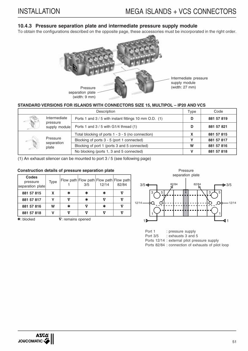
51
MEGA ISLANDS + VCS CONNECTORS
STANDARD VERSIONS FOR ISLANDS WITH CONNECTORS SIZE 15, MULTIPOL – IP20 AND VCSDescription CodeType
Pressureseparationplate
Intermediatepressuresupply module
Ports 1 and 3 / 5 with instant fittings 10 mm O.D. (1) D 881 57 819
Ports 1 and 3 / 5 with G1/4 thread (1) D 881 57 821
Total blocking of ports 1 - 3 - 5 (no connection) X 881 57 815
Blocking of ports 3 - 5 (port 1 connected) Y 881 57 817
Blocking of port 1 (ports 3 and 5 connected) W 881 57 816
No blocking (ports 1, 3 and 5 connected) V 881 57 818
(1) An exhaust silencer can be mounted to port 3 / 5 (see following page)
Intermediate pressuresupply module(width: 27 mm)Pressure
separation plate(width: 9 mm)
10.4.3 Pressure separation plate and intermediate pressure supply moduleTo obtain the configurations described on the opposite page, these accessories must be incorporated in the right order.
Construction details of pressure separation plate
Codespressure
separation plateType Flow path
1Flow path
3/5Flow path
12/14Flow path
82/84
881 57 815 X ∇∇∇∇∇
881 57 817 Y ∇∇∇∇∇ ∇∇∇∇∇ ∇∇∇∇∇
881 57 816 W ∇∇∇∇∇ ∇∇∇∇∇
881 57 818 V ∇∇∇∇∇ ∇∇∇∇∇ ∇∇∇∇∇ ∇∇∇∇∇
: blocked ∇∇∇∇∇: remains opened
3/5
1
12/14
82/84
3 5
1
3 5
1
82/84 3/5
1
12/14
Pressureseparation plate
Port 1 : pressure supplyPort 3/5 : exhausts 3 and 5Ports 12/14 : external pilot pressure supplyPorts 82/84 : connection of exhausts of pilot loop
INSTALLATION
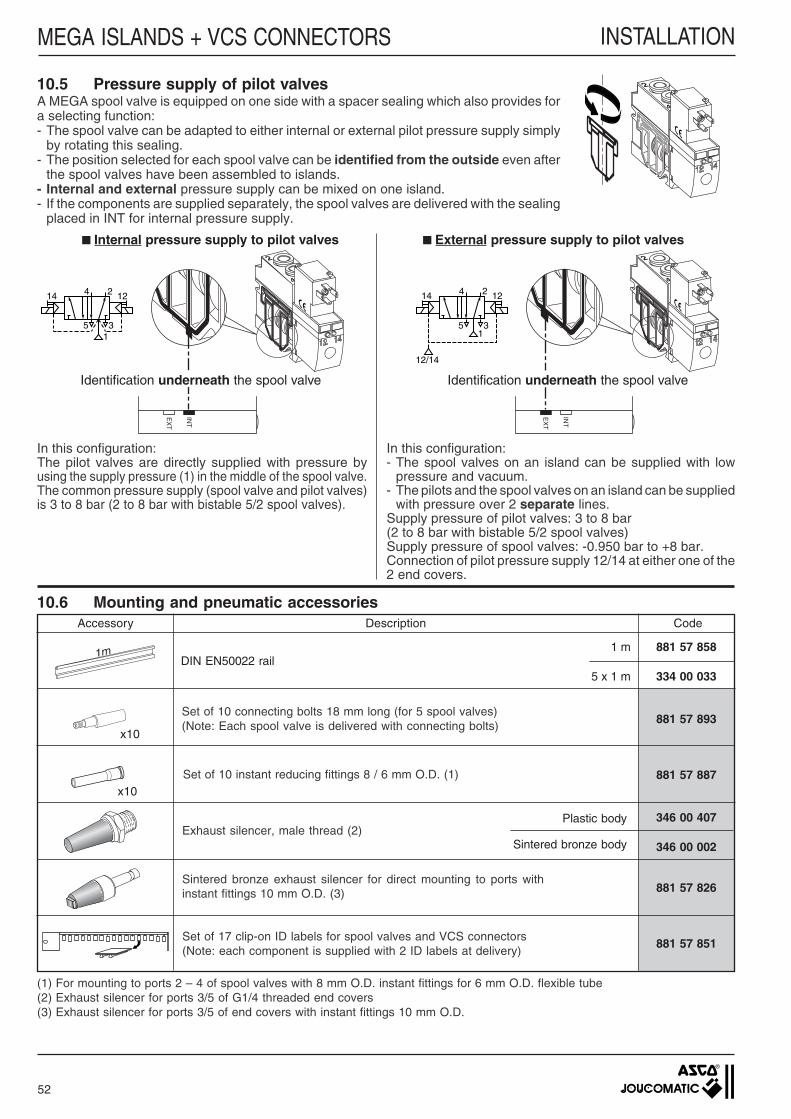
52
MEGA ISLANDS + VCS CONNECTORS
INT
EX
T
INT
EX
T
10.6 Mounting and pneumatic accessoriesAccessory Description Code
DIN EN50022 rail
Set of 10 connecting bolts 18 mm long (for 5 spool valves)(Note: Each spool valve is delivered with connecting bolts)
Set of 10 instant reducing fittings 8 / 6 mm O.D. (1)
Exhaust silencer, male thread (2)
Sintered bronze exhaust silencer for direct mounting to ports withinstant fittings 10 mm O.D. (3)
Set of 17 clip-on ID labels for spool valves and VCS connectors(Note: each component is supplied with 2 ID labels at delivery)
881 57 858
334 00 033
881 57 893
881 57 887
346 00 407
346 00 002
881 57 826
881 57 851
1 m
5 x 1 m
1m
(1) For mounting to ports 2 – 4 of spool valves with 8 mm O.D. instant fittings for 6 mm O.D. flexible tube(2) Exhaust silencer for ports 3/5 of G1/4 threaded end covers(3) Exhaust silencer for ports 3/5 of end covers with instant fittings 10 mm O.D.
x10
x10
10.5 Pressure supply of pilot valvesA MEGA spool valve is equipped on one side with a spacer sealing which also provides fora selecting function:- The spool valve can be adapted to either internal or external pilot pressure supply simply
by rotating this sealing.- The position selected for each spool valve can be identified from the outside even after
the spool valves have been assembled to islands.- Internal and external pressure supply can be mixed on one island.- If the components are supplied separately, the spool valves are delivered with the sealing
placed in INT for internal pressure supply.
Internal pressure supply to pilot valves External pressure supply to pilot valves
Identification underneath the spool valve
In this configuration:The pilot valves are directly supplied with pressure byusing the supply pressure (1) in the middle of the spool valve.The common pressure supply (spool valve and pilot valves)is 3 to 8 bar (2 to 8 bar with bistable 5/2 spool valves).
In this configuration:- The spool valves on an island can be supplied with low
pressure and vacuum.- The pilots and the spool valves on an island can be supplied
with pressure over 2 separate lines.Supply pressure of pilot valves: 3 to 8 bar(2 to 8 bar with bistable 5/2 spool valves)Supply pressure of spool valves: -0.950 bar to +8 bar.Connection of pilot pressure supply 12/14 at either one of the2 end covers.
Identification underneath the spool valve
Sintered bronze body
Plastic body
INSTALLATION
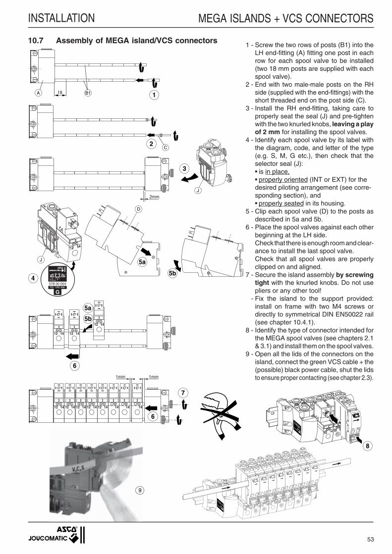
1 - Screw the two rows of posts (B1) into theLH end-fitting (A) fitting one post in eachrow for each spool valve to be installed(two 18 mm posts are supplied with eachspool valve).
2 - End with two male-male posts on the RHside (supplied with the end-fittings) with theshort threaded end on the post side (C).
3 - Install the RH end-fitting, taking care toproperly seat the seal (J) and pre-tightenwith the two knurled knobs, leaving a playof 2 mm for installing the spool valves.
4 - Identify each spool valve by its label withthe diagram, code, and letter of the type(e.g. S, M, G etc.), then check that theselector seal (J):• is in place,• properly oriented (INT or EXT) for thedesired piloting arrangement (see corre-sponding section), and• properly seated in its housing.
5 - Clip each spool valve (D) to the posts asdescribed in 5a and 5b.
6 - Place the spool valves against each otherbeginning at the LH side.Check that there is enough room and clear-ance to install the last spool valve.Check that all spool valves are properlyclipped on and aligned.
7 - Secure the island assembly by screwingtight with the knurled knobs. Do not usepliers or any other tool!
- Fix the island to the support provided:install on frame with two M4 screws ordirectly to symmetrical DIN EN50022 rail(see chapter 10.4.1).
8 - Identify the type of connector intended forthe MEGA spool valves (see chapters 2.1& 3.1) and install them on the spool valves.
9 - Open all the lids of the connectors on theisland, connect the green VCS cable + the(possible) black power cable, shut the lidsto ensure proper contacting (see chapter 2.3).
53
MEGA ISLANDS + VCS CONNECTORSINSTALLATION
10.7 Assembly of MEGA island/VCS connectors
3
J2mm
1B118A
2C
5a
D
J
P(1): _ 0.9/3...8 bar
24
35182/84
1214
1412
G
578 00 0044
5b
12 14 12 14
12 14
5a
5b
6
7
12 14 12 14 12 14 12 14 12 14 14 14 14
6
1mm 1mm
8
9
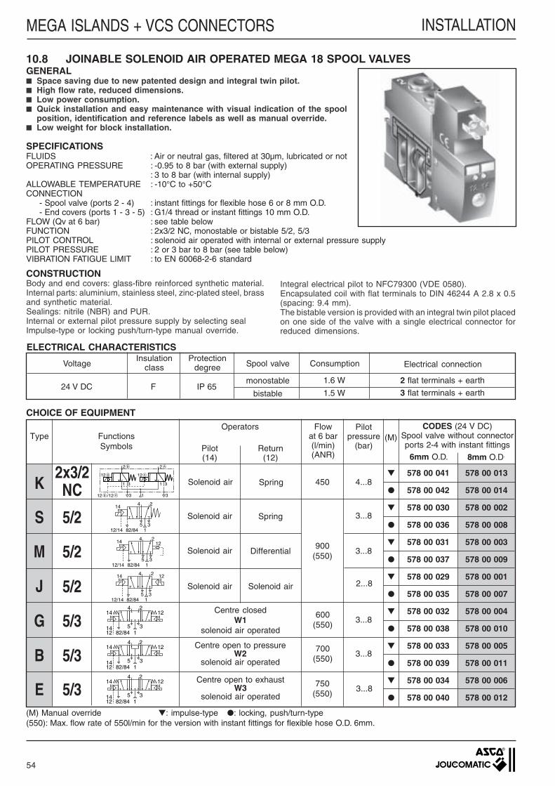
54
MEGA ISLANDS + VCS CONNECTORS INSTALLATION
CODES (24 V DC)Spool valve without connectorports 2-4 with instant fittings
578 00 041 578 00 013
578 00 042 578 00 014
578 00 030 578 00 002
578 00 036 578 00 008
578 00 031 578 00 003
578 00 037 578 00 009
578 00 029 578 00 001
578 00 035 578 00 007
578 00 032 578 00 004
578 00 038 578 00 010
578 00 033 578 00 005
578 00 039 578 00 011
578 00 034 578 00 006
578 00 040 578 00 012
10.8 JOINABLE SOLENOID AIR OPERATED MEGA 18 SPOOL VALVESGENERAL Space saving due to new patented design and integral twin pilot. High flow rate, reduced dimensions. Low power consumption. Quick installation and easy maintenance with visual indication of the spool
position, identification and reference labels as well as manual override. Low weight for block installation.
SPECIFICATIONSFLUIDS : Air or neutral gas, filtered at 30µm, lubricated or notOPERATING PRESSURE : -0.95 to 8 bar (with external supply)
: 3 to 8 bar (with internal supply)ALLOWABLE TEMPERATURE : -10°C to +50°CCONNECTION
- Spool valve (ports 2 - 4) : instant fittings for flexible hose 6 or 8 mm O.D.- End covers (ports 1 - 3 - 5) : G1/4 thread or instant fittings 10 mm O.D.
FLOW (Qv at 6 bar) : see table belowFUNCTION : 2x3/2 NC, monostable or bistable 5/2, 5/3PILOT CONTROL : solenoid air operated with internal or external pressure supplyPILOT PRESSURE : 2 or 3 bar to 8 bar (see table below)VIBRATION FATIGUE LIMIT : to EN 60068-2-6 standard
Solenoid air Solenoid air
Electrical connectionSpool valve
monostable
bistable
Protectiondegree
Insulationclass ConsumptionVoltage
2 flat terminals + earth
3 flat terminals + earthIP 65F24 V DC
CHOICE OF EQUIPMENT
Return(12)
Pilot(14)
5/2
5/3
Centre closedW1
solenoid air operated
Centre open to exhaustW3
solenoid air operated
Centre open to pressureW2
solenoid air operated
900(550)
Solenoid air Differential
FunctionsSymbols
Flowat 6 bar(l/min)(ANR)
Operators(M)
14 2
35
4
182/8412/14
Solenoid air Spring
14 2
35
4
182/84
12
12/14
12
12/14
2
35
4
182/84
14
24
182/84
1214
1412
35
24
182/84
1214
1412
35
24
182/84
1214
1412
35
(M) Manual override : impulse-type : locking, push/turn-type(550): Max. flow rate of 550l/min for the version with instant fittings for flexible hose O.D. 6mm.
6mm O.D. 8mm O.D.
1.5 W
2x3/2NC
Solenoid air Spring
Pilotpressure
(bar)
450
600(550)
700(550)
750(550)
4...8
3...8
3...8
2...8
3...8
3...8
3...8
5/2
5/2
5/3
5/3
M
B
S
G
E
K
Type
J
ELECTRICAL CHARACTERISTICS
CONSTRUCTIONBody and end covers: glass-fibre reinforced synthetic material.Internal parts: aluminium, stainless steel, zinc-plated steel, brassand synthetic material.Sealings: nitrile (NBR) and PUR.Internal or external pilot pressure supply by selecting sealImpulse-type or locking push/turn-type manual override.
Integral electrical pilot to NFC79300 (VDE 0580).Encapsulated coil with flat terminals to DIN 46244 A 2.8 x 0.5(spacing: 9.4 mm).The bistable version is provided with an integral twin pilot placedon one side of the valve with a single electrical connector forreduced dimensions.
1.6 W
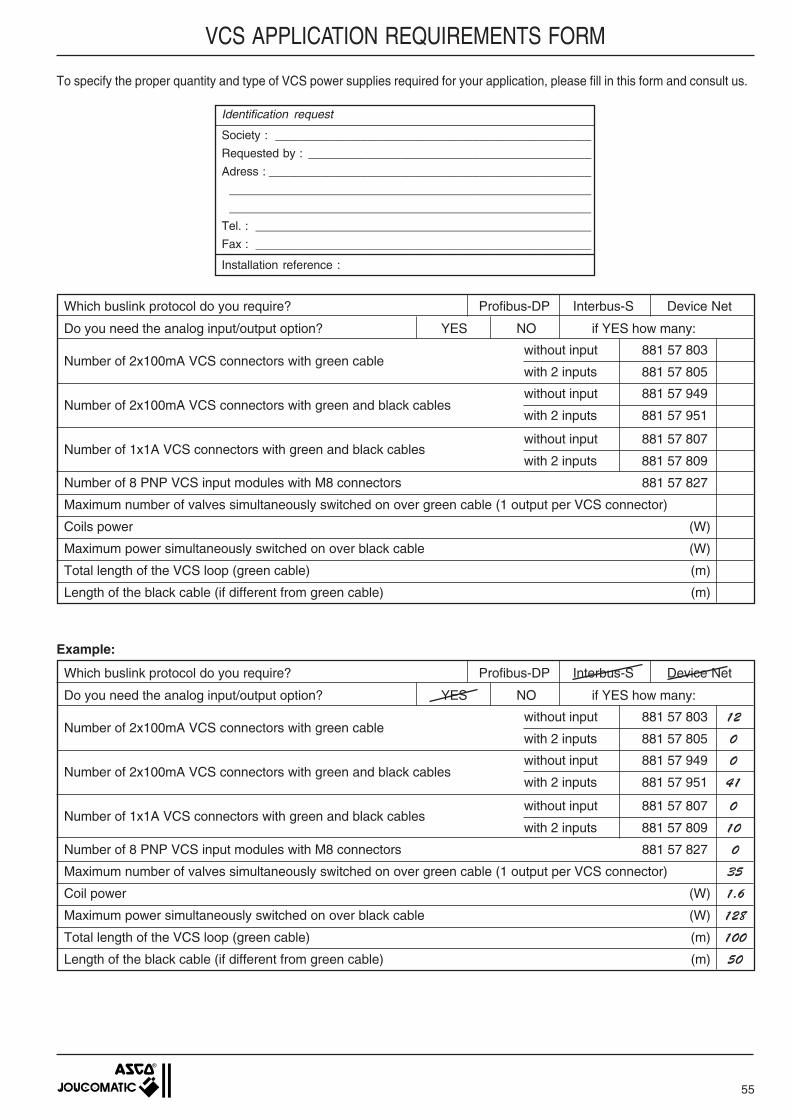
55
VCS APPLICATION REQUIREMENTS FORM
To specify the proper quantity and type of VCS power supplies required for your application, please fill in this form and consult us.
Which buslink protocol do you require? Profibus-DP Interbus-S Device Net
Do you need the analog input/output option? YES NO if YES how many:
Number of 2x100mA VCS connectors with green cable
Number of 2x100mA VCS connectors with green and black cables
Number of 1x1A VCS connectors with green and black cables
Number of 8 PNP VCS input modules with M8 connectors 881 57 827
Maximum number of valves simultaneously switched on over green cable (1 output per VCS connector)
Coils power (W)
Maximum power simultaneously switched on over black cable (W)
Total length of the VCS loop (green cable) (m)
Length of the black cable (if different from green cable) (m)
without input 881 57 803
with 2 inputs 881 57 805
without input 881 57 949
with 2 inputs 881 57 951
without input 881 57 807
with 2 inputs 881 57 809
Example:
Which buslink protocol do you require? Profibus-DP Interbus-S Device Net
Do you need the analog input/output option? YES NO if YES how many:
Number of 2x100mA VCS connectors with green cable
Number of 2x100mA VCS connectors with green and black cables
Number of 1x1A VCS connectors with green and black cables
Number of 8 PNP VCS input modules with M8 connectors 881 57 827 0
Maximum number of valves simultaneously switched on over green cable (1 output per VCS connector) 35
Coil power (W) 1.6
Maximum power simultaneously switched on over black cable (W) 128
Total length of the VCS loop (green cable) (m) 100
Length of the black cable (if different from green cable) (m) 50
without input 881 57 803 12
with 2 inputs 881 57 805 0
without input 881 57 949 0
with 2 inputs 881 57 951 41
without input 881 57 807 0
with 2 inputs 881 57 809 10
Identification request
Society : ________________________________________________
Requested by : ___________________________________________
Adress : _________________________________________________
_______________________________________________________
_______________________________________________________
Tel. : ___________________________________________________
Fax : ___________________________________________________
Installation reference :