Embed Size (px)
Citation preview
1
5JST
1
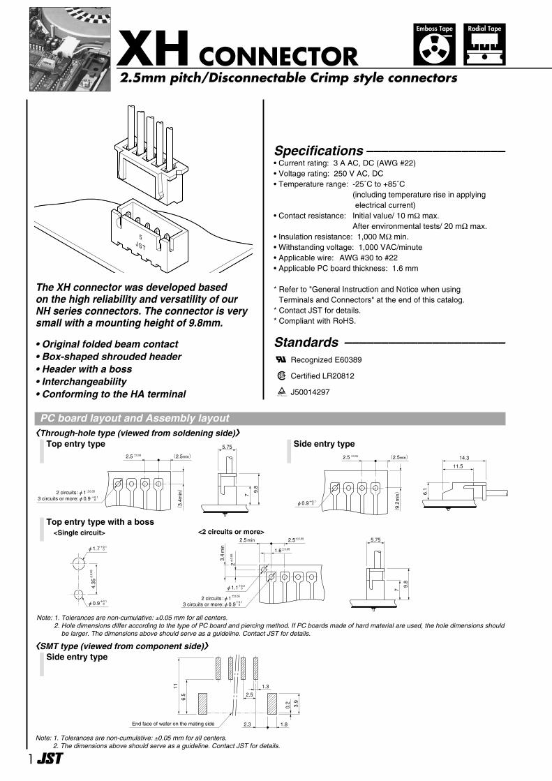
The XH connector was developed based on the high reliability and versatility of ourNH series connectors. The connector is verysmall with a mounting height of 9.8mm.
Specifications –––––––––––––––––––• Current rating: 3 A AC, DC (AWG #22)• Voltage rating: 250 V AC, DC• Temperature range: -25˚C to +85˚C
(including temperature rise in applyingelectrical current)
• Contact resistance: Initial value/ 10 mΩ max. After environmental tests/ 20 mΩ max.
• Insulation resistance: 1,000 MΩ min. • Withstanding voltage: 1,000 VAC/minute • Applicable wire: AWG #30 to #22• Applicable PC board thickness: 1.6 mm
* Refer to "General Instruction and Notice when using Terminals and Connectors" at the end of this catalog.
* Contact JST for details.* Compliant with RoHS.
Standards ––––––––––––––––––––––0 Recognized E60389
1Certified LR20812
2J50014297
XH CONNECTOR2.5mm pitch/Disconnectable Crimp style connectors
Radial TapeEmboss Tape
2.5 ±0.05 (2.5min)
(3.4min)
5.75
7
9.8
±0.05 2 circuits :φ13 circuits or more:φ0.9 +0.1 0
14.3
11.5
6.1
2.5 ±0.05 (2.5min)
(9.2min)
φ0.9+0.1 0
Top entry type Side entry type
2.5±0.052.5min
3.4min
2±0.05
1.6±0.05
±0.05
4.35
φ0.9+0.1 0
φ1.7+0.1 0
+0.2 0
±0.05 2 circuits :φ13 circuits or more:φ0.9+0.1 0
φ1.1
5.75
7
9.8
Top entry type with a boss
0.2 3.9
11
6.5
1.82.3
2.5
1.3
End face of wafer on the mating side
〈Through-hole type (viewed from soldening side)〉
Note: 1. Tolerances are non-cumulative: ±0.05 mm for all centers.2. The dimensions above should serve as a guideline. Contact JST for details.
• Original folded beam contact• Box-shaped shrouded header• Header with a boss• Interchangeability• Conforming to the HA terminal
<Single circuit> <2 circuits or more>
Note: 1. Tolerances are non-cumulative: ±0.05 mm for all centers.2. Hole dimensions differ according to the type of PC board and piercing method. If PC boards made of hard material are used, the hole dimensions should
be larger. The dimensions above should serve as a guideline. Contact JST for details.
Side entry type〈SMT type (viewed from component side)〉
PC board layout and Assembly layout
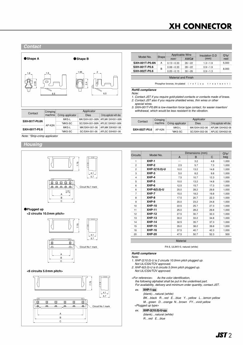
RoHS complianceNote:1. XHP-2(10.0)-U is 2 circuits 10.0mm pitch plugged up.
Not UL/CSA/TUV approved.2. XHP-6(5.0)-U is 6 circuits 5.0mm pitch plugged up.
Not UL/CSA/TUV approved.
<For reference> As the color identification, the following alphabet shall be put in the underlined part.For availability, delivery and minimum order quantity, contact JST.
ex. XHP-1-oo-(blank)…natural (white)BK…black R…red E…blue Y…yellow L…lemon yellowM…green D…orange N…brown FY…vivid yellow
<Plugged up type>
ex. XHP-2(10.0)-U-oo-(blank)…natural (white)R…red E…blue
2
XH CONNECTOR
1.8 1.6
6.5
2.35
1.95
6.5
2
2.4
7.75
4.1
5.7
A
BC
Circuit No.1 mark
7.75
4.1
5.7
2.5A
BC
Circuit No.1 mark
7.75
4.1
5.7
A
B
C
Circuit No.1 mark
Material and Finish
Model No.Applicable Wire Q'ty/
reelmm2 AWG#Insulation O.D
(mm)
Phosphor bronze, tin-plated (reflow treatment)
SXH-001T-P0.6NSXH-001T-P0.6 SXH-002T-P0.6
0.13~0.33
0.08~0.33
0.05~0.13
26~22
28~22
30~26
1.3~1.9
0.9~1.9
0.9~1.3
5,000
8,000
Shape
A
B
RoHS complianceNote: 1. Contact JST if you require gold-plated contacts or contacts made of brass. 2. Contact JST also if you require shielded wires, thin wires or other
special wires.3. SXH-001T-P0.6N is low-insertion force type contact, for easier insertion/
withdrawal, which would be less resistant to the vibration.
Shape A Shape B
Circuits Model No.Dimensions (mm) Q'ty/
bagA C
Material
PA 6, UL94V-0, natural (white)
B 1
2 2
3
4
5
6
6
7
8
9
10
11
12
13
14
15
16
20
XHP-1XHP-2XHP-2(10.0)-U XHP-3XHP-4XHP-5XHP-6XHP-6(5.0)-UXHP-7XHP-8XHP-9XHP-10XHP-11XHP-12XHP-13XHP-14XHP-15XHP-16XHP-20
―
2.5
10.0
5.0
7.5
10.0
12.5
25.0
15.0
17.5
20.0
22.5
25.0
27.5
30.0
32.5
35.0
37.5
47.5
3.2
5.7
13.2
8.2
10.7
13.2
15.7
28.2
18.2
20.7
23.2
25.7
28.2
30.7
33.2
35.7
38.2
40.7
50.7
4.8
7.3
14.8
9.8
12.3
14.8
17.3
29.8
19.8
22.3
24.8
27.3
29.8
32.3
34.8
37.3
39.8
42.3
52.3
1,000
1,000
1,000
1,000
1,000
1,000
1,000
1,000
1,000
1,000
1,000
1,000
1,000
1,000
1,000
1,000
1,000
1,000
500
ContactCrimp applicator Dies Crimp applicator with dies
Applicator
SXH-001T-P0.6NAP-K2N
MKS-L
*MKS-SC
MK/SXH-001-06N
SC/SXH-001-06N
SXH-001T-P0.6MKS-L
*MKS-SC
MK/SXH-001-06
SC/SXH-001-06
APLMK SXH001-06N
APLSC SXH001-06N
APLMK SXH001-06
APLSC SXH001-06
Note: *Strip-crimp applicator
ContactCrimp applicator Dies Crimp applicator with dies
Applicator
SXH-002T-P0.6 AP-K2NMKS-L
*MKS-SC
MK/SXH-002-06
SC/SXH-002-06
APLMK SXH002-06
APLSC SXH002-06
Plugged up
<6 circuits 5.0mm pitch>
<2 circuits 10.0mm pitch>
Contact
Crimpingmachine
Crimpingmachine
Housing
3
XH CONNECTOR
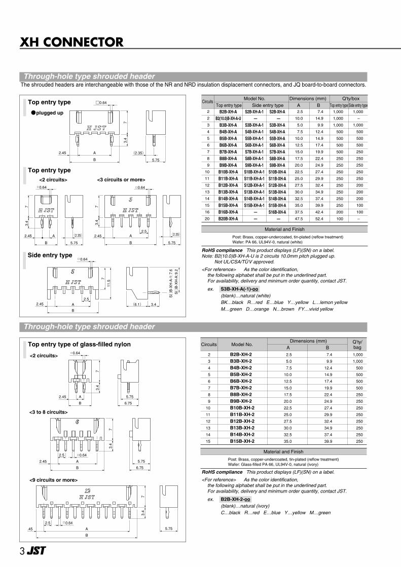
Top entry type of glass-filled nylon Circuits Model No.Dimensions (mm) Q’ty/
bagA B2
3
4
5
6
7
8
9
10
11
12
13
14
15
B2B-XH-2B3B-XH-2B4B-XH-2B5B-XH-2B6B-XH-2B7B-XH-2B8B-XH-2B9B-XH-2B10B-XH-2B11B-XH-2B12B-XH-2B13B-XH-2B14B-XH-2B15B-XH-2
2.5
5.0
7.5
10.0
12.5
15.0
17.5
20.0
22.5
25.0
27.5
30.0
32.5
35.0
7.4
9.9
12.4
14.9
17.4
19.9
22.4
24.9
27.4
29.9
32.4
34.9
37.4
39.9
1,000
1,000
500
500
500
500
250
250
250
250
250
250
250
250
Material and Finish
Post: Brass, copper-undercoated, tin-plated (reflow treatment)Wafer: Glass-filled PA 66, UL94V-0, natural (ivory)
<2 circuits>
<3 to 8 circuits>
<9 circuits or more>
B
A2.45
73.4
73.4
73.4
0.64
5.75
6.75
5.75
5.75
6.75
2.5
2.45 A
B
0.64
2.5
.45 A
B
0.64
0.64
(2.35)A2.45
B 5.75
3.4
7
A
B
2.45
3.4
7
5.75
(2.35)2.5
0.64
A
B
2.452.5
(6.1) 3.4
711.5
0.64
S( ) B-XH-A-1:7.6
S( ) B-XH-A:9.2
Top entry type
Top entry type<2 circuits>
plugged up
<3 circuits or more>
Side entry type
Material and Finish
Dimensions (mm)A B Top entry type Side entry type
Q'ty/boxCircuits
Model No.Top entry type Side entry type
B2B-XH-A B2(10.0)B-XH-A-U
B3B-XH-A B4B-XH-A B5B-XH-A B6B-XH-A B7B-XH-A B8B-XH-A B9B-XH-A
B10B-XH-A B11B-XH-A B12B-XH-A B13B-XH-A B14B-XH-A B15B-XH-A B16B-XH-A B20B-XH-A
2
2
3
4
5
6
7
8
9
10
11
12
13
14
15
16
20
2.5
10.0
5.0
7.5
10.0
12.5
15.0
17.5
20.0
22.5
25.0
27.5
30.0
32.5
35.0
37.5
47.5
7.4
14.9
9.9
12.4
14.9
17.4
19.9
22.4
24.9
27.4
29.9
32.4
34.9
37.4
39.9
42.4
52.4
1,000
1,000
1,000
500
500
500
500
250
250
250
250
250
250
250
250
200
100
1,000
–
1,000
500
500
500
250
250
250
250
250
200
200
200
100
100
–
S2B-XH-A-1 —
S3B-XH-A-1 S4B-XH-A-1 S5B-XH-A-1 S6B-XH-A-1 S7B-XH-A-1 S8B-XH-A-1 S9B-XH-A-1
S10B-XH-A-1 S11B-XH-A-1 S12B-XH-A-1 S13B-XH-A-1 S14B-XH-A-1 S15B-XH-A-1
——
Post: Brass, copper-undercoated, tin-plated (reflow treatment) Wafer: PA 66, UL94V-0, natural (white)
S2B-XH-A —
S3B-XH-A S4B-XH-A S5B-XH-A S6B-XH-A S7B-XH-A S8B-XH-A S9B-XH-A
S10B-XH-A S11B-XH-A S12B-XH-A S13B-XH-A S14B-XH-A S15B-XH-A S16B-XH-A
—
RoHS compliance This product displays (LF)(SN) on a label.Note: B2(10.0)B-XH-A-U is 2 circuits 10.0mm pitch plugged up.
Not UL/CSA/TUV approved.
<For reference> As the color identification, the following alphabet shall be put in the underlined part.For availability, delivery and minimum order quantity, contact JST.
ex. S3B-XH-A(-1)-oo-(blank)…natural (white)BK…black R…red E…blue Y…yellow L…lemon yellowM…green D…orange N…brown FY…vivid yellow
RoHS compliance This product displays (LF)(SN) on a label.
<For reference> As the color identification, the following alphabet shall be put in the underlined part.For availability, delivery and minimum order quantity, contact JST.
ex. B2B-XH-2-oo-(blank)…natural (ivory)C…black R…red E…blue Y…yellow M…green
0.64
73.4
2.45 A
B
(2.35)
5.75
Through-hole type shrouded headerThe shrouded headers are interchangeable with those of the NR and NRD insulation displacement connectors, and JQ board-to-board connectors.
Through-hole type shrouded header
4
XH CONNECTOR
6
5.5
2.5
B
A3.75
0.64
7 (3)
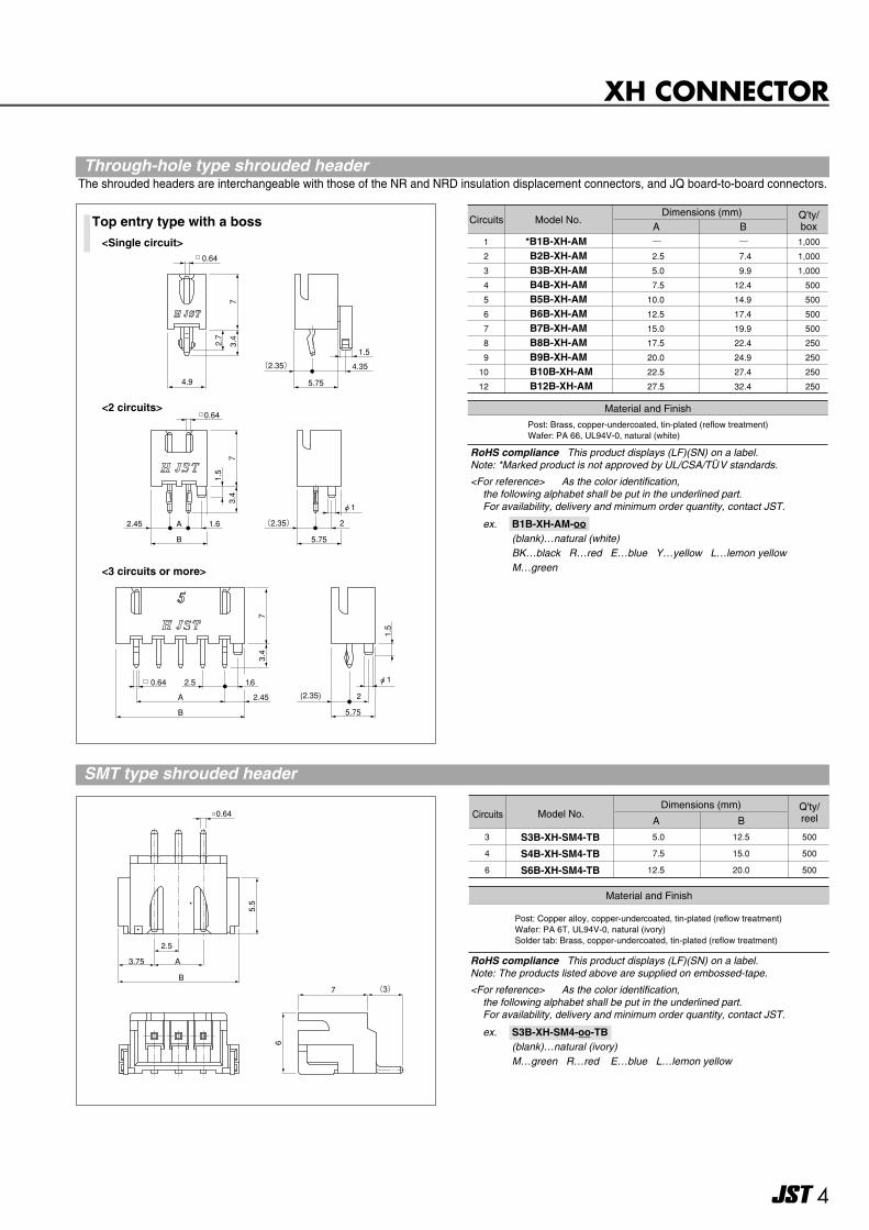
Circuits Model No.Dimensions (mm) Q'ty/
boxA B1
2
3
4
5
6
7
8
9
10
12
*B1B-XH-AM B2B-XH-AM B3B-XH-AM B4B-XH-AM B5B-XH-AM B6B-XH-AM B7B-XH-AM B8B-XH-AM B9B-XH-AM B10B-XH-AM B12B-XH-AM
―
2.5
5.0
7.5
10.0
12.5
15.0
17.5
20.0
22.5
27.5
―
7.4
9.9
12.4
14.9
17.4
19.9
22.4
24.9
27.4
32.4
1,000
1,000
1,000
500
500
500
500
250
250
250
250
Material and Finish
Post: Brass, copper-undercoated, tin-plated (reflow treatment) Wafer: PA 66, UL94V-0, natural (white)
RoHS compliance This product displays (LF)(SN) on a label.Note: *Marked product is not approved by UL/CSA/TUV standards.
<For reference> As the color identification, the following alphabet shall be put in the underlined part.For availability, delivery and minimum order quantity, contact JST.
ex. B1B-XH-AM-oo-(blank)…natural (white)BK…black R…red E…blue Y…yellow L…lemon yellowM…green
Top entry type with a boss
<2 circuits>
<Single circuit>
<3 circuits or more>
0.64
(2.35)
4.9 5.75
4.35
3.4
7
2.7
1.5
0.64
(2.35)A2.45
B 5.75
1.6 2
3.4
7
1.5
φ1
0.64
A
B
2.45
7
φ1
5.75
2.5 1.6
2(2.35)
3.4
1.5
Circuits Model No.Dimensions (mm)
A BQ'ty/reel
Material and Finish
5.0
7.5
12.5
S3B-XH-SM4-TB
S4B-XH-SM4-TB
S6B-XH-SM4-TB
12.5
15.0
20.0
500
500
500
3
4
6
Post: Copper alloy, copper-undercoated, tin-plated (reflow treatment) Wafer: PA 6T, UL94V-0, natural (ivory)Solder tab: Brass, copper-undercoated, tin-plated (reflow treatment)
RoHS compliance This product displays (LF)(SN) on a label.Note: The products listed above are supplied on embossed-tape.
<For reference> As the color identification, the following alphabet shall be put in the underlined part.For availability, delivery and minimum order quantity, contact JST.
ex. S3B-XH-SM4-oo-TB-(blank)…natural (ivory)M…green R…red E…blue L…lemon yellow
Through-hole type shrouded headerThe shrouded headers are interchangeable with those of the NR and NRD insulation displacement connectors, and JQ board-to-board connectors.
SMT type shrouded header
5
XH CONNECTOR
2.5
B
A
2.45
72.80.64
6.75
φ( 0.7)
2.5
B
A
2.45
72.80.64
6.75
φ( 0.7)
2.5
7.4
2.45
0.64
7
6.75
φ( 0.7)
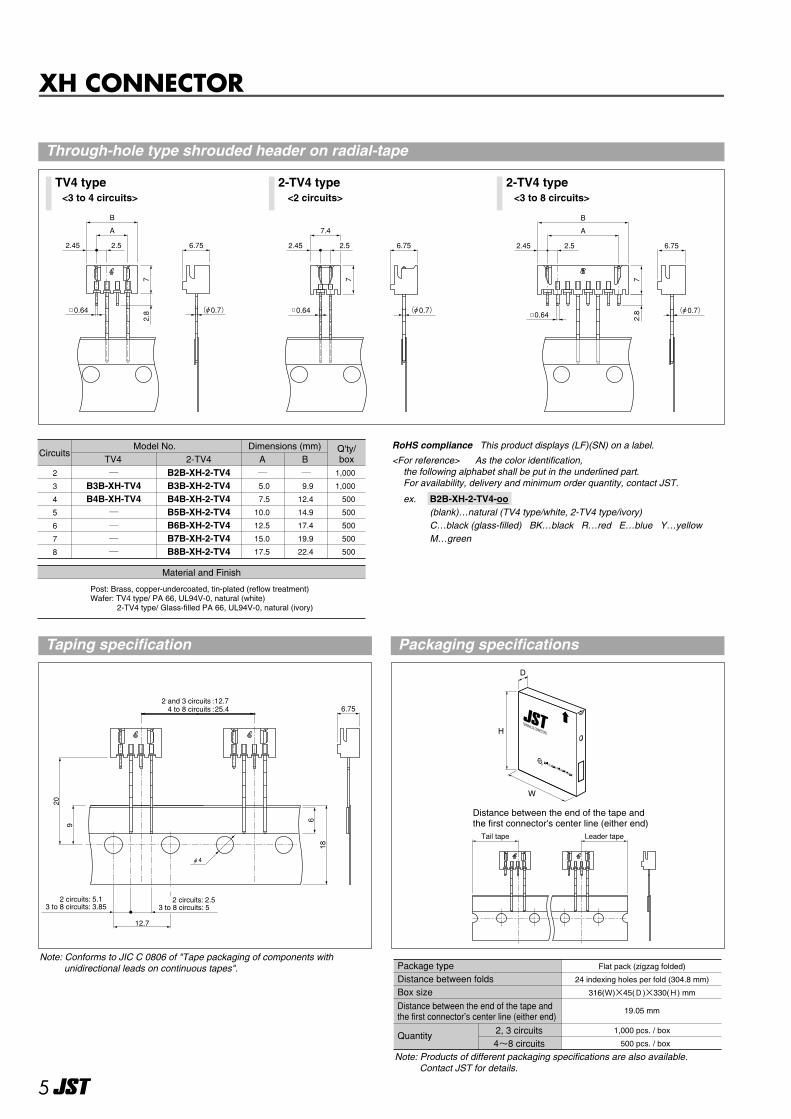
TV4 type 2-TV4 type 2-TV4 type
CircuitsModel No. Dimensions (mm)
A BTV4 2-TV42
3
4
5
6
7
8
―B3B-XH-TV4B4B-XH-TV4
――――
B2B-XH-2-TV4B3B-XH-2-TV4B4B-XH-2-TV4B5B-XH-2-TV4B6B-XH-2-TV4B7B-XH-2-TV4B8B-XH-2-TV4
Material and Finish
Post: Brass, copper-undercoated, tin-plated (reflow treatment)Wafer: TV4 type/ PA 66, UL94V-0, natural (white) 2-TV4 type/ Glass-filled PA 66, UL94V-0, natural (ivory)
― 5.0
7.5
10.0
12.5
15.0
17.5
― 9.9
12.4
14.9
17.4
19.9
22.4
1,000
1,000
500
500
500
500
500
Q'ty/box
RoHS compliance This product displays (LF)(SN) on a label.
<For reference> As the color identification, the following alphabet shall be put in the underlined part.For availability, delivery and minimum order quantity, contact JST.
ex. B2B-XH-2-TV4-oo-(blank)…natural (TV4 type/white, 2-TV4 type/ivory)C…black (glass-filled) BK…black R…red E…blue Y…yellowM…green
12.7
20
9
6
18
φ4
6.75
2 circuits: 5.13 to 8 circuits: 3.85
2 circuits: 2.53 to 8 circuits: 5
2 and 3 circuits :12.74 to 8 circuits :25.4
Note: Conforms to JIC C 0806 of "Tape packaging of components withunidirectional leads on continuous tapes".
<3 to 4 circuits> <3 to 8 circuits><2 circuits>
Through-hole type shrouded header on radial-tape
Taping specification Packaging specifications
TERMINALS & CONNECTORS
R
D
H
W
Leader tapeTail tape
Flat pack (zigzag folded)
24 indexing holes per fold (304.8 mm)
316(W)×45(D)×330(H) mm
1,000 pcs. / box
500 pcs. / box
19.05 mm
2, 3 circuits4~8 circuits
Package typeDistance between foldsBox sizeDistance between the end of the tape and the first connector’s center line (either end)
Quantity
Note: Products of different packaging specifications are also available. Contact JST for details.
Distance between the end of the tape andthe first connector's center line (either end)