Embed Size (px)
Citation preview

CX3 Issue 1 Scope Communications UK Ltd, Quantum House, Totnes, Devon TQ9 5AL United Kingdom
Tel:+44 (0)1803 860700 Fax: +44 (0)1803 863716 www.scope-uk.com
Connexions CX3
Radio Paging Transcoder Mains, Two Port Version
Installation & User Manual
ConneXions CX3 Mains, Two Port Version
CX3 Issue 1
Page 1 of 13
PREFACE
Important Installation Information It is the purchasers’ responsibility to determine the suitability of this equipment and its derivatives for any given application, Scope cannot give specific advice in this manual, as each use will require independent evaluation. Scope has, wherever possible, employed extra safeguards to monitor the system’s performance. Certain system installations, operational requirements or budgets may, however, limit the effectiveness of these safeguards. Again, the suitability of the system for any given application must therefore be decided by the installer and their customer, relative to the application and risk. Good working practice dictates that a suitable system installation log must be generated, together with a record of the dates when the system has been manually checked, (with the aid of signal strength meters etc.) enabling the system performance to be compared with the original installation data. For UK equipment, Scope has no control of the use and application of the frequencies issued by OFCOM. Some equipment that is licensed may have greater protection than other equipment which is operated on a WT Act License Exempt basis. The supply of this equipment is governed by our standard terms and conditions of sale, which can be found on the reverse of all order acknowledgements*, proforma invoices*, delivery notes, price lists and invoices. Alternatively, these can be provided on request. * Faxed proforma invoices and quotations refer to “conditions available upon request”. Important Safety Information Scope products are designed to operate safely when installed and used according to general safety practices. The following requirements should be observed at all times. Do NOT subject this equipment to: Mechanical shock Excessive humidity or moisture Extremes of temperature Corrosive liquids This equipment is designed for indoor use, unless expressly stated otherwise, and must not be used in classified Hazardous Areas, including areas containing explosive or flammable vapours, unless express authorisation has been given in writing by the manufacturer. If in doubt, consult your local product dealer for further information. Do not obstruct any slots or openings in the product. These are provided for ventilation to ensure reliable operation of the product and to protect it from overheating. Only use a damp cloth for cleaning (not liquid or aerosol based cleaners), and ensure that any power is removed from the unit prior to beginning the cleaning operation. Removal of covers from the equipment must only be undertaken by authorised service personnel, who must ensure that power is isolated prior to removal.

ConneXions CX3 Mains, Two Port Version
CX3 Issue 1
Page 2 of 13
Preface Installation Installation must only be undertaken by an Approved contractor, who shall ensure that all work is carried out in compliance with National Wiring Regulations. For mains powered equipment, a readily accessible isolating fuse or switched socket must be located within 1 metre of the equipment. No User Serviceable Parts Alteration or modification to any part of this equipment, without the prior written consent of the manufacturer, will invalidate all Approvals and Warranties attaching to the equipment. Further liability for the operation of the equipment, under the applicable law, will pass to the user, who will absolve the manufacturer of any further responsibility for it’s correct operation and use. Liability Scope does not accept liability for any damage or injury, howsoever caused as the result of misuse of this equipment. It is the responsibility of the user to ensure that the equipment is operated in the manner for which it was intended and that it is the correct item of equipment for the required task. Warranty This product is warranted as free from defects of workmanship and materials for a period of one year from the original purchase date. During this time, if there is a defect or malfunction of this product, Scope will, with proof of purchase, repair or replace at it’s discretion any defective parts, free of charge. This does not include where the adjustments, parts and repair are necessary due to circumstances beyond the control of Scope, including but not limited to fire or other casualty, accident, neglect, abuse, abnormal use or battery leakage damage.
WARNING! No User Serviceable Parts Celui-ci ne contient aucune piece pouvant etre reparee par l’utilisateur
Caution! Risk of electric shock, do not open.
Attention ! Risque de choc electrique, ne pas ouvrir. Alteration or modification to any part of this equipment, without the prior written consent of the manufacturer, will invalidate all manufacturer approvals and warranties. No adjustments can be undertaken except by qualified and licensed persons as authorised by Scope.
WARNING! SAFETY This equipment must only be used with an Approved mains cord set rated at 5A minimum which is fitted with an integral three prong, grounded mains plug and a moulded IEC320 style socket. The cord set must only be plugged into a grounded, fused outlet rated 5A minimum. This product complies with the essential requirements of the R&TTE Directive 1999/5/EC
Copies of the Declaration of Conformity covering this product can be obtained from Scope at: Quantum House, Steamer Quay, Totnes TQ9 5AL United Kingdom.
Do not discard. At end of life this equipment must be sent to an authorised waste treatment centre.
Contact Scope at the above address for further details.
© Scope Communications UK Ltd, 2008 All Rights Reserved. E & OE.
ConneXions CX3 Mains, Two Port Version
CX3 Issue 1
Page 3 of 13
System Overview
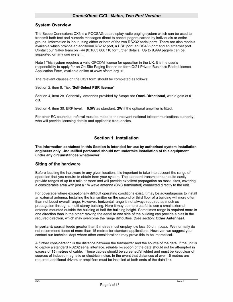
The Scope Connexions CX3 is a POCSAG data display radio paging system which can be used to transmit both text and numeric messages direct to pocket pagers carried by individuals or entire groups. Information is input using either or both of the two RS232 serial ports. There are also models available which provide an additional RS232 port, a USB port, an RS485 port and an ethernet port. Contact our Sales team on +44 (0)1803 860710 for further details. Up to 9,999 pagers can be supported on any one system. Note ! This system requires a valid OFCOM licence for operation in the UK. It is the user’s responsibility to apply for an On-Site Paging licence on form Of21 Private Business Radio Licence Application Form, available online at www.ofcom.org.uk. The relevant clauses on the Of21 form should be completed as follows: Section 2, item 9. Tick “Self-Select PBR licence” Section 4, item 28. Generally, antennas provided by Scope are Omni-Directional, with a gain of 0 dB. Section 4, item 30. ERP level: 0.5W as standard, 2W if the optional amplifier is fitted. For other EC countries, referral must be made to the relevant national telecommunications authority, who will provide licensing details and applicable frequencies.
Section 1: Installation The information contained in this Section is intended for use by authorised system installation engineers only. Unqualified personnel should not undertake installation of this equipment under any circumstances whatsoever. Siting of the hardware
Before locating the hardware in any given location, it is important to take into account the range of operation that you require to obtain from your system. The standard transmitter can quite easily provide ranges of up to a mile or more and will provide excellent propagation on most sites, covering a considerable area with just a 1/4 wave antenna (BNC terminated) connected directly to the unit. For coverage where exceptionally difficult operating conditions exist, it may be advantageous to install an external antenna. Installing the transmitter on the second or third floor of a building will more often than not boost overall range. However, horizontal range is not always required as much as propagation through a multi storey building. Here it may be more useful to use a small external antenna mounted outside the building at half the building height. Sometimes range is required more in one direction than in the other: moving the aerial to one side of the building can provide a bias in the required direction, which may overcome the range difficulties. (See section: Other Antennas). Important: coaxial feeds greater than 5 metres must employ low loss 50 ohm coax. We normally do not recommend feeds of more than 15 metres for standard applications. However, we suggest you contact our technical dept where other considerations may prove this to be impractical. A further consideration is the distance between the transmitter and the source of the data. If the unit is to deploy a standard RS232 serial interface, reliable reception of the data should not be attempted in excess of 15 metres of cable. These cables should be screened/shielded and must be kept clear of sources of induced magnetic or electrical noise. In the event that distances of over 15 metres are required, additional drivers or amplifiers must be installed at both ends of the data link.
ConneXions CX3 Mains, Two Port Version
CX3 Issue 1
Page 4 of 13
Some major points to consider when installing equipment: 1 Never install antennas near or adjacent to telephone, public address or data communication lines or overhead power cables. 2 Avoid, where ever possible, running antenna coax alongside other cables. 3 Avoid mounting the transmitter in the immediate vicinity of telephone
exchanges or computer equipment. 4 Always use proprietary 50 ohm coaxial cable between the antenna and the transmitter. If cable runs exceed 5 metres, always use low loss 50 ohm cable such as RG213, UR67 or equivalent. Coaxial cable intended for TV, Satellite or CCTV installations is normally 75 OHM and therefore totally unsuitable for any transmitter installation manufactured by Scope. 5 Also remember that the performance of the system will be effected by the type
of material the unit is mounted on and its surroundings.
The following is a list of materials that this transmitter will be adversely affected by if mounted on or if mounted in close proximity to:
a) Foil back plasterboard b) Metal mesh or wire reinforced glass c) Metal sheeting, large mirrors or suspended ceilings d) Lift shafts
All of the above can reflect radio waves and thereby reduce the capability of the transmitter to perform its desired functions.
6 The circuit boards within this equipment may be harmed by Electrostatic
Discharge (ESD). Installers should ensure that both themselves and the system’s chassis are grounded before beginning any installation, and should ensure that adequate anti-static procedures are adhered to at all times.
7 Warning! Never transmit without an aerial attached to the transmitter 8 Warning! Carefully check the Installation section in this manual covering
data pin connections prior to installation. Damage caused by incorrect connection is the responsibility of the installer!
Installation The following procedure must be adhered to when installing the ConneXions paging system. Ensure you have taken into consideration all of the above information before selecting the location for your transmitter. If in doubt please feel free to telephone the technical helpline on +44 (1803) 860710. 1 Remove the cover from the ConneXions transmitter unit by slackening the four Pozi head screws located at the top and bottom of the unit (see Diagram 1).

ConneXions CX3 Mains, Two Port Version
CX3 Issue 1
Page 5 of 13
2 Carefully lift off the cover and set aside. 3 The transmitter should be fixed to an even wall surface using suitable screws fitted through
the holes provided in the chassis plate. Hold the chassis up to the chosen location and with the aid of a pencil mark the position of the mounting holes.
Warning: Do not use the chassis plate as a template for drilling the holes into the wall. Hammer drills vibrating through the chassis may irreparably damage the quartz crystals on the printed circuit boards. 4 Place the ConneXions transmitter over the mounting holes and secure the unit with suitable
screws. Check that the chassis plate does not bend and that the screws do not snag or pinch any of the internal cables.
5 Connect the antenna to the unit via the BNC connector located at the top of the housing. If
the antenna is an external antenna, or an antenna which is separate from the transmitter unit itself, ensure that the previous criteria covered under the section headed Siting of the Hardware, have been strictly adhered to (also see section headed Other Antennas).
6 It is important to note that due to the number of interfaces brought out to the 9-way ‘D’
connectors, great care should be taken to use only the lines which are applicable to your installation. Failure to comply with this instruction will almost certainly DESTROY the unit.
In your application the transcoder has been configured as RS232 inputs on COM1 & COM2. COM1 & COM2 RS232 SERIAL PORTS (9 way D Type Plug) PIN SIGNAL DIRECTION 1 N/C 2 RECEIVE DATA (RX) IN 3 TRANSMIT DATA (TX) OUT 4 DATA TERMINAL READY (DTR) OUT 5 GROUND (GND) 6 N/C 7 REQUEST TO SEND (RTS) OUT 8 CLEAR TO SEND (CTS) IN 9 +5V 100mA max (for Scope peripherals) As information passes only from the host equipment to the ConneXions transcoder, you will only need to read the DTR line which if high shows that power is applied to the Connexions unit. The RTS line will be high when the transcoder is ready to receive data. The ConneXions RTS line should be connected to the host CTS line to facilitate correct handshaking. Prior to connecting the data cable, thoroughly check the system pin connections as shown above. Then connect the data cable from the host to COM1 or COM2 on the ConneXions unit 7 If the unit is supplied with a sealed lead acid battery, the flying lead connector should be
plugged into the header marked “Battery” (CN2) on the SMPS15 Power Supply unit. The battery will now be in circuit and the unit will power up (red power LED will light on lower chassis plate). Note: if battery fuse (F1) requires replacement at any time, use only type 2A Anti-Surge (AS), 1.25”.
8 Replace the cover and re-tighten the four retaining screws. 9 Finally, after checking all connections, insert the mains cable supplied into the IEC type connector located at the base of the unit and plug in to a suitable switched wall outlet. With mains power applied, the red LED on the base of the unit should be lit. 10 The system is now ready to accept calls from the host terminal. When a call is transmitted, the
green LED on the base of the unit will light momentarily.

ConneXions CX3 Mains, Two Port Version
CX3 Issue 1
Page 6 of 13
DIAGRAM 1
ConneXions CX3 Mains, Two Port Version
CX3 Issue 1
Page 7 of 13
Section 2: System Operation
Confirmation of power connection is by way of the red LED on the base of the transcoder console. Confirmation of transmit is provided by way of the momentary green LED on the base of the transcoder console. Sending data in the correct format (see Technical Section, Calling Pagers) will invoke transmitted messages to the relevant pagers. Problems and Fault Finding. 1 Check and re-check the data cable connections. This, together with an incorrect signalling format, result in more faults than any other problem. 2 Check that the communications baud rate of the host equipment matches that of the
Connexions COM ports. The default baud rate settings on the Connexions are: COM1 = 1200 baud, COM2 = 9600 baud (check configuration data supplied with
your order, see label on inside of chassis). 3 Check that the pagers are at least 3 metres from the transmitter and aerial. Under certain conditions it is possible to flood the pager receivers and corrupt the data received. 4 Check that the pagers have the battery installed with the correct polarity and are
correctly powered up. Check the pager baud rate and frequency matches the Connexions transmitter (see label on inside of chassis plate).
5 Check that the red power LED on the base of the transcoder is lit. If not, remove the
mains cord set and check that mains is available at the supply outlet. 6 Check that the green LED lights for the duration of the transmission. If not, go back to the data cabling and re-check the signal format. 7 Check that the aerial is correctly installed. IMPORTANT: Isolate mains before removing cover. Internal access and adjustments strictly limited to authorised service personnel only. Radio Transmission Baud Rate This is set at the factory to suit the pagers supplied and will normally be set at either 512 or 1200 baud. Please refer to the separate configuration sheet and/or delivery note supplied with your unit.

ConneXions CX3 Mains, Two Port Version
CX3 Issue 1
Page 8 of 13
Optional Dry Contacts
This option must be specified at time of ordering, along with the pre-programmed messages required. The purchaser should also order the dry contact interface box (Part Code: DC8) for ease of connection to the contact terminals (see Diagram 2).
Warning! Voltages applied to any of these contacts will cause irreparable damage! This unit can support up to 8 dry (volt-free) contacts on PL1, which, when shorted to ground, will send a pre-programmed message to a particular pager address (which could be to an individual, a group or all pager operatives at the same time). These messages are pre-programmed and can only be changed by qualified service personnel. The trigger time required to send a message must be greater than 1 second. Individual messages can be sent upon both changes of state with a maximum alphanumeric length of 69 characters.
ConneXions CX3 Mains, Two Port Version
CX3 Issue 1
Page 9 of 13
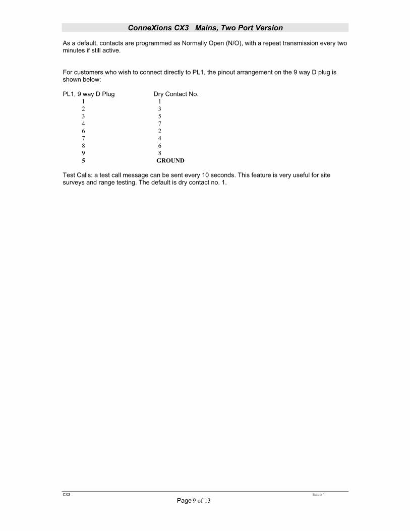
As a default, contacts are programmed as Normally Open (N/O), with a repeat transmission every two minutes if still active. For customers who wish to connect directly to PL1, the pinout arrangement on the 9 way D plug is shown below: PL1, 9 way D Plug Dry Contact No. 1 1 2 3 3 5 4 7 6 2 7 4 8 6 9 8 5 GROUND Test Calls: a test call message can be sent every 10 seconds. This feature is very useful for site surveys and range testing. The default is dry contact no. 1.
ConneXions CX3 Mains, Two Port Version
CX3 Issue 1
Page 10 of 13
Other Antennas The range and performance of this equipment can be improved by the addition of more efficient antennas*. These can be installed either inside or outside the building and are connected to the transmitter with 50 OHM coaxial cable. Glass mount antenna (UHFGM): for installation on the inside of a suitable window. This can boost range, especially if it is required in one direction from the building. The centre fed half wave di-pole, measuring approximately 12 inches from tip to tip, will provide excellent all round local signalling. This can be mounted either inside or outside a building. Two versions are available: 1) a light duty antenna suitable for sheltered environments/internal installation (LUHFDP). 2) a heavy duty stainless unit with optional mounting hardware for more arduous applications (UHFDP). Other antennas, including co-linears, are available for external applications. Pre-terminated coaxial feeder cables are available for 5, 10 or 15 metre requirements. Consult our Sales Department for further details. Note ! High frequencies can equate to high power losses. Always use quality cable. RG58 is only acceptable on cable runs of up to 5 metres. We recommend RG213, or equivalent, on greater lengths. If in doubt consult our Technical Department. *subject to license conditions. Specifically, mounting height and Effective Radiated Power (ERP). Service Information If you experience a problem with your equipment you must first telephone our service hotline, where we may request that you undertake a few simple checks. If a problem still remains, we will arrange collection of your system by overnight carrier at our expense. Upon receipt, we will endeavour to service or replace the system within 24 working hours and return the same by overnight carrier. We suggest that you retain the packaging for your control equipment. Incorrectly packed goods returned for service are the responsibility of the customer. If we deem that new packaging is required before we can return the unit, a charge will be made. In the event that a pager requires service, return it directly to Scope (in the pre-addressed service bag supplied with your system) by registered post. Ensure that you carefully fill out the service form provided. Failure to complete this form in full will result in inevitable delays! Pagers returned with flat, incorrectly installed or leaking batteries will be charged for! Record your system details here for quick reference:- Date supplied____/____/____ Serial Number of the base console_________ Transmitter frequency _______MHz Transmitter Type: ECOLINK. Model: CX3 Number of pagers supplied with the system _______ System base ID number__________________ Transmitter baud rate ______________ Serial input baud rate_____________ For information on individual pager types, refer to the appropriate pager manual For information on use with the telephone I/F, refer to the separate Telephone Interface manual.
ConneXions CX3 Mains, Two Port Version
CX3 Issue 1
Page 11 of 13
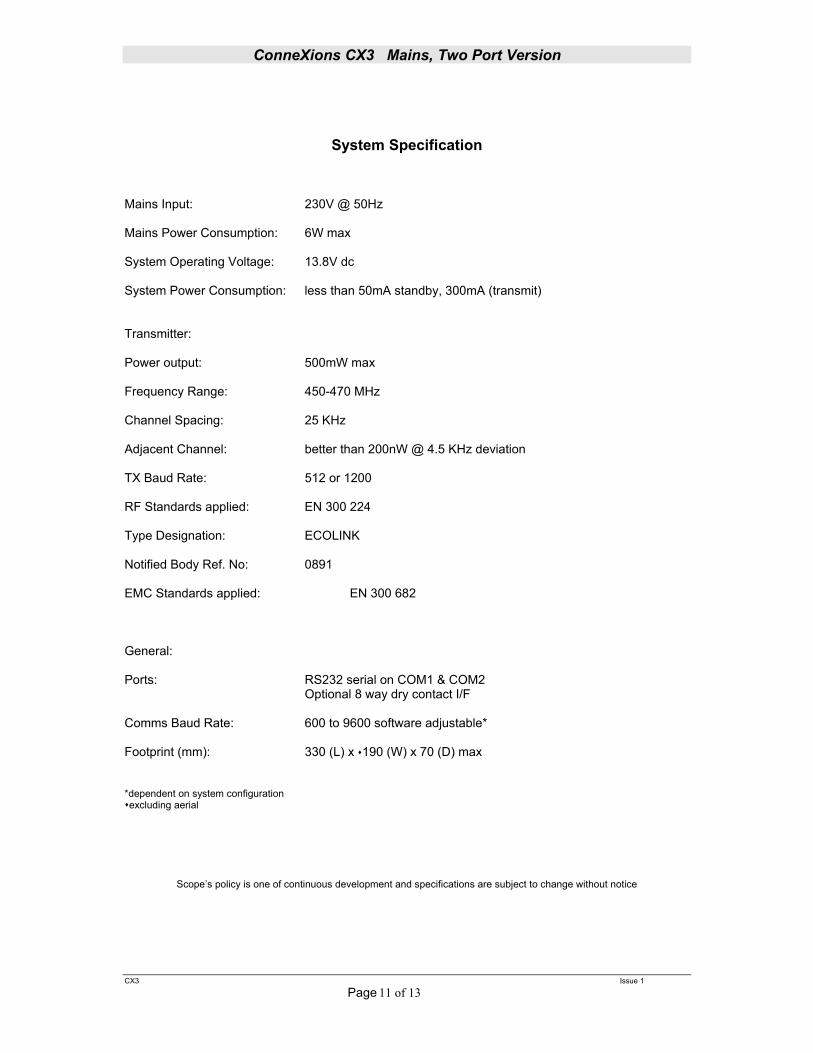
System Specification Mains Input: 230V @ 50Hz Mains Power Consumption: 6W max System Operating Voltage: 13.8V dc System Power Consumption: less than 50mA standby, 300mA (transmit) Transmitter: Power output: 500mW max Frequency Range: 450-470 MHz Channel Spacing: 25 KHz Adjacent Channel: better than 200nW @ 4.5 KHz deviation TX Baud Rate: 512 or 1200 RF Standards applied: EN 300 224 Type Designation: ECOLINK Notified Body Ref. No: 0891 EMC Standards applied: EN 300 682 General: Ports: RS232 serial on COM1 & COM2 Optional 8 way dry contact I/F Comms Baud Rate: 600 to 9600 software adjustable* Footprint (mm): 330 (L) x 190 (W) x 70 (D) max *dependent on system configuration excluding aerial
Scope’s policy is one of continuous development and specifications are subject to change without notice

ConneXions CX3 Mains, Two Port Version
CX3 Issue 1
Page 12 of 13
Section 3: Technical Information This section provides a more in depth understanding of how messages are formatted for serial communication from a host. It need only be studied by those intending to write their own serial comm.’s software. Calling Pagers Pagers all use 7 digit numeric addresses which enables the system to support thousands of pagers without identity clashes. Most pagers will support multiple addresses (sometimes referred to as CAP codes, RIC’s or identities). This enables the pager not only to respond to its own unique address but also to respond to group or global addresses. These real 7 digit numeric codes are often substituted for shorter logical numbers which are easier to remember. Under these conditions the host or speciality program within the transcoder will perform an algorithm on the data string received to convert the simpler logical number back into a real 7 digit number for transmission. For improved data recovery without error the real 7 digit pager numbers are always spaced 8 digits apart. To avoid system identity clashes, transcoders are provided with a base number within the range of 1000 to 1,999,000. If for example a base address of 0100,000 is applied to a transcoder, the first real pager number will 0100,008 followed by 0100,016 and so on. Logical pager numbers are normally used on systems fitted with the telephone interface and those which are interfaced to personal computers. The algorithm would perform the following function:- For example take the logical pager number of 123 The logical pager number 123 will be multiplied by 8 and then added to the base number to provide the 7 digit real number Logical No Base No Real No 123 x 8 = 984 + 0100,000 = 0100984 Pager address 1 is normally reserved as the personal identity for that specific pager. Other addresses, of which there can be 6 or more, can be tagged to specific pagers to form selected groups. Address 2 could, for example, be used for all pagers to formulate a global call. Address codes can be divided between full addresses and sub addresses. Full addresses can allow four different bleep types, A, B, C or D, whereas sub-addresses will only accommodate a fixed bleep type. A status line of information will normally be provided on the pager screen which will highlight the type of bleep sent together with other status information. Numeric Pagers Example serial message string:- N0012300A1234567890<CR> The ‘N’ informs the transcoder that this message is destined for a Numeric pager. Any data not preceded by this will be ignored.
ConneXions CX3 Mains, Two Port Version
CX3 Issue 1
Page 13 of 13
Section 3: Technical Information
Next follows the 7 digit pager identity number. All seven digits must be used. The letter following the identity is the beep type of which there are four valid characters, A, B, C or D. Next follows the message to be transmitted, which can include: 0-9, space, -(hyphen), ‘U’ (letter U for ‘U’rgent), [,] open/close square brackets, (open square brackets can also be used to identify the letter ‘C’ for ‘C’ancel). The final character sent is ‘carriage return’ which is not transmitted but represents the end of message marker. On sending a message to the unit in the correct format the transcoder will immediately recompose the string into the POCSAG format and transmit the same at the pre-programmed baud rate. This will be accompanied by the green LED lighting for the same period to show that data is being transmitted. The time taken to transmit the message is dependent upon the pager baud rate. For 512 baud this is approximately 4 seconds, whilst at 1200 baud the time is approximately 2 seconds. The unit can accept sequential data at 9600 baud which will be buffered and dealt with as soon as the preceding transmission has ended. The RTS line from the transcoder will only go high in the unlikely event that the message buffer is full. Alphanumeric Pagers Example serial message string:- A0012300A This is a message <CR> The data format is exactly as for numeric pagers, except that the recognition character at the front of the message is changed from an ‘N’ to an ‘A’. Transmission baud rate: in the above example, the default baud rate is sent. To change the transmission baud rate in a message string, placing a letter “N” after the “A” will alter it to 512 baud. Placing a letter “F” after the “A” will alter it to 1200 baud. The default setting for the Connexions CX3 is 512 baud.
************************************************************************

ConneXions CX3 Mains, Two Port Version
CX3 1 Issue 1
Programming The ConneXions 3 issue 9 can be programmed by the end-user using the supplied Microsoft Windows™ Compatible Scope Configuration Utility program ConX-Lite. The software will allow the user to upload protocols changes on each serial port using the supplied files. Additionally messages and condition of dry contact inputs can be modified. Install
1. Insert CD in to CD/CD-RW drive 2. Click Start, Run, Browse and locate CD Drive: Conx-Lite: 3. Double click Setup then OK. 4. After installation of the Conx-Lite program is complete you must copy the files from the
data directory on the cd to the C:\Program Files\ConX-Pro Configuration 5. The program is now installed.

ConneXions CX3 Mains, Two Port Version
CX3/2 2 ISSUE 1
Communications
1. Connect the supplied null modem interconnect cable to the ConneXions 3 issue 9 and the computer.
2. Run the Conx3 ConX-Lite Configuration program. 3. When the program first activates, the word Disconnected in red will appear under the Scope
logo. 4. All programming changes to the unit will be accomplished via communications port 1. 5. Select the Comms tab. 6. If the user is not sure what the baud rate of the system to be programmed is, click on the
button Auto Baud Detect. This will set the program communication port 1 to the correct baud rate.
7. Select Connect. The word disconnect will change to Connected in green. 8. The unit is ready to be programmed.

ConneXions CX3 Mains, Two Port Version
CX3/2 3 ISSUE 1
Programming Refer to the below chart for the correct file to be loaded. Each file has been configured and tested. No modifications to these file are possible. If additional configurations or changes must be made contact your dealer. File Name: scopeall.conx9 Protocol Port Port Setting Type Pager Baud Alert Base ID scope Com Port #1 9600 n-8-1 Alpha 1200 D None scope Com Port #2 9600 n-8-1 Alpha 1200 D None File Name: scopescope.conx9 Protocol Port Port Setting Type Pager Baud Alert Base ID scope Com Port #1 9600 n-8-1 Alpha 512 A None scope Com Port #2 9600 n-8-1 Alpha 512 A None File Name:comp2comp2.conx9 Protocol Port Port Setting Type Pager Baud Alert Base ID comp2 Com Port #1 9600 n-8-1 Alpha 1200 A 0010000 comp2 Com Port #2 9600 n-8-1 Alpha 1200 A 0010000 File Name:comp2.conx9 Protocol Port Port Setting Type Pager Baud Alert Base ID comp2 Com Port #1 9600 n-8-1 Alpha 1200 A 0300000 comp2 Com Port #2 9600 n-8-1 Alpha 1200 A 0300000 File Name: tapall.conx9 Protocol Port Port Setting Type Pager Baud Alert Base ID tap v1.8 Com Port #1 9600 n-8-1 Alpha 1200 None None tap v1.8 Com Port #2 9600 n-8-1 Alpha 1200 None None File Name: comp2tele.conx9 Protocol Port Port Setting Type Pager Baud Alert Base ID comp2 Com Port #1 9600 n-8-1 Alpha 1200 A 0600000 telealarm Com Port #2 9600 e-7-1 Alpha 512 None None File Name:scopetele.conx9 Protocol Port Port Setting Type Pager Baud Alert Base ID Scope Com Port #1 9600 n-7-1 Alpha 512 None None telealarm Com Port #2 9600 e-7-1 Alpha 512 None None File Name: tapscope.conx9 Protocol Port Port Setting Type Pager Baud Alert Base ID tap v1.8 Com Port #1 9600 n-8-1 Alpha 1200 None None scope Com Port #2 9600 n-8-1 Alpha 1200 D None File Name: scopecomp2.conx9 Protocol Port Port Setting Type Pager Baud Alert Base ID scope Com Port #1 9600 n-8-1 Alpha 1200 D None comp2 Com Port #2 9600 n-8-1 Alpha 1200 D 0600000

ConneXions CX3 Mains, Two Port Version
CX3/2 ISSUE 1
File Name: scopecomp1.conx9 Protocol Port Port Setting Type Pager Baud Alert Base ID scope Com Port #1 9600 n-8-1 Alpha 1200 D None comp1 Com Port #2 9600 n-8-1 Alpha 1200 A 0500008 File Name: comp1comp1.conx9 Protocol Port Port Setting Type Pager Baud Alert Base ID comp1 Com Port #1 9600 n-8-1 Alpha 1200 D 0200008 comp1 Com Port #2 9600 n-8-1 Alpha 1200 A 0200008 File Name: taptele.conx9 Protocol Port Port Setting Type Pager Baud Alert Base ID tap v1.8 Com Port #1 9600 n-8-1 Alpha 1200 none none telealarm Com Port #2 9600 e-7-1 Alpha 512 none none Loading File
1. Click Read, the program will read the file configuration that is currently in the unit and now the
Write selection will be available. 2. Select FILE, OPEN. 3. Select the file to be loaded and click OPEN. 4. Click on Write. 5. After the file has been uploaded, click Reset ConX9. 6. The Connexions 3 now has the protocol and port configurations as show in the chart above. Note: Remove the power and re-apply power before placing the unit into service.
4

ConneXions CX3 Mains, Two Port Version
CX3/2 5 ISSUE 1
Contact Configuration
1. Select the Contacts tab. 2. Select the contact to be configured by clicking on the tab at the right. 3. Each contact has three options; Open, Closed or Toggle (change of state). 4. Enter the required data for each contact. 5. After all data has been entered, click on Write, this will upload the changes
to the unit. This will not effect the programming of the protocols. Read/Write/Connect/Reset CX3
1. Read – Read data from unit connected. 2. Write – Write all changes to unit connected. 3. Connect – Will connect unit to software program. 4. Reset Conx9 – The Conx9 must be reset each time changes are made. If not, the changes will
not take effect. There are two ways to reset the unit. 1.) Power the unit off and on, 2.) Click the reset conx9 button.