Embed Size (px)
Citation preview
CONSIDERATIONS IN CONVERTING A DUAL SHELL OR A DUAL PRESSURE COAL FIRED PLANT CONDENSER INTO A COMBINED CYCLE PLANT CONDENSER
Ranga Nadig, Ph.D.
Maarky Thermal Systems Inc. 1415, Route 70 East, Suite 604,
Cherry Hill, NJ, 08034, USA
ABSTRACT The design of a dual shell or a dual pressure condenser employed in a coal fired plant is different from that in a combined cycle plant. The coal fired plant dual pressure condenser is equipped with feedwater heaters in the condenser neck, extraction piping, an external flash tank and a large number of vents and drains. Dual shell or dual pressure condenser in a combined cycle plant does not include feedwater heaters in the condenser neck and the related extraction piping. There is no external flash tank and the number of vents and drains are minimal. Combined cycle plants have a higher steam flowrate, are required to operate in bypass mode and in certain instances have high make up water flowrate. Apart from the above major differences there are a number of minor differences that must be accounted and addressed when converting a coal fired plant dual shell or dual pressure condenser into a combined cycle plant condenser. This paper highlights the major and minor differences in the design, construction and operation of dual shell or dual pressure condenser operating in a coal fired plants and combined cycle plant. The modifications required to convert the condenser from coal fired application to combined cycle application are discussed. Precautions to be followed in operating the condenser in the new role are addressed.
INTRODUCTION Extensive capital investment to modernize ageing and inefficient coal fired plant, expensive equipment required to meet present day environmental regulations and lower prices of natural gas have nudged numerous generators in USA to shut down the existing coal fired plants entirely or convert the coal fired plants into gas fired plants. In some cases the coal fired boilers are converted into gas fired boilers. In other instances the existing coal fired boilers are replaced with more efficient combinations of combustion turbines and heat recovery steam generators (HRSG). In both scenarios the existing balance of plant equipment is modified and refurbished and then pressed into service. When the coal fired plant is shut down in its entirety the equipment in the plant is mothballed or sold on the secondary market. A steam surface condenser is an important component of a power plant. Smaller power plants are equipped with a single shell condenser. Larger power plants usually employ “dual shell” or “dual pressure” condenser. A “dual shell condenser” consists of two identical shells operating at the same shell side pressure. The hotwells and the steam domes of the two shells are connected. In a “dual pressure condenser” the two shells operate at different pressures. Circulating water enters the low pressure shell and upon exiting enters the high pressure shell. Cycle efficiency is improved by partially heating the condensate from low pressure shell in the hotwell of the high pressure shell.
Proceedings of the ASME 2013 Power Conference POWER2013
July 29-August 1, 2013, Boston, Massachusetts, USA
POWER2013-98062
1 Copyright © 2013 by ASME

Although the operating principle is the same there are substantial differences in the design and construction of coal fired and combined cycle plant condensers. Combined cycle plants have higher turbine exhaust steam flowrates when compared to coal fired plants and are often required to operate for a short or extended duration in bypass mode. The coal fired plants employ pressurized deaerators that remove the oxygen from the condensate. In combined cycle plants the deaeration of condensate is carried out in the condenser. Combined cycle plants, serving as cogeneration plants, dispatch a portion of turbine extraction steam for heating purposes. In such scenarios an equivalent quantity of makeup water is introduced and deaerated in the condenser. In coal fired plants large quantities of vents and drains are admitted directly or through a flash tank into the condenser. In combined cycle plants the limited amount of vents and drains are often introduced directly into the condenser. There are number of design features that are common to dual shell and dual pressure condenser that must be addressed when converting a coal fired plant into a combined cycle plant condenser. In addition dual pressure and dual shell condensers have some unique features that must be accounted for. A summary of the common and unique features of dual shell and dual pressure condensers that that must be accounted for is included in the following section. DESIGN FEATURES COMMON TO DUAL SHELL AND DUAL PRESSURE CONDENSER Adequacy of Heat Transfer Surface and Support Plate Spacing The heat transfer surface in the existing condenser should be sufficient to meet the performance required in the combined cycle application. The existing support plate spacing should be less than that required for the revised turbine exhaust steam flow rate in the combined cycle operation. As the condenser will be operating in bypass operation for short or extended periods it is prudent, as a minimum, to increase the thickness of the tubes in the impingement zone. If permissible the top two rows of tubes in the impingement zone should be replaced by two rows of 14 BWG carbon steel dummy tubes. This would result in the loss of heat transfer in the top two rows of tubes and plugging the tubesheet holes. However, this modification will avoid tube failures and protect the impingement zone tubes from steam impingement during normal and bypass operation. Feedwater Heater in the Steam Dome The dual shell as well as the dual pressure condenser in a coal fired plant is equipped with low pressure feedwater heaters installed in the condenser neck. Typically LP1A, LP2A are installed in the steam dome of one of the first shell and LP1B & LP2B are installed in the steam dome of the second shell. In certain instances the low pressure
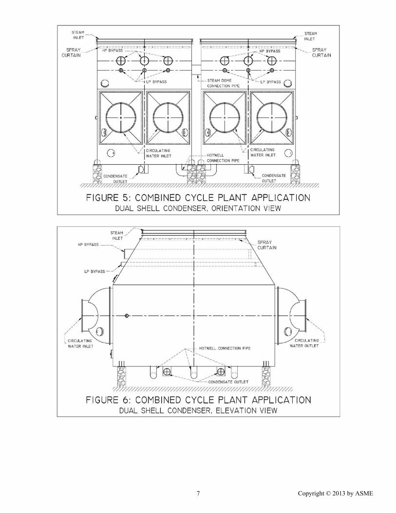
heaters 1A and 1B are combined into a duplex heater. In such a scenario each shell will include one duplex heater. These feedwater heaters are removed when converting a coal fired plant condenser into a combined cycle plant condenser. Extreme care must be exercised in removing the heater and the heater supports so that the condenser internals especially the tubes are not damaged. The opening in the steam dome plate occupied by the feedwater heater must be replaced with a cover plate adequately stiffened in conjunction with the steam dome stiffeners to withstand the shellside design pressure. The extraction piping from the steam turbine must be removed. The ends of the extraction piping must be capped. Drain connections must be installed on the end caps. The drain connection must be routed to the condenser hotwell. The ends of the extraction piping must be adequately stiffened. Bypass Headers A combined cycle plant condenser is required to condense the steam from the HRSG/pressure reducing desuperheating valve when the steam turbine is not in operation. This type of operation is typically referred to as bypass operation. To facilitate bypass operation, bypass headers must be installed in the steam done. Typical bypass operation hardware includes HP bypass header, IP bypass header and LP bypass header. Each HRSG will have its own HP, IP and LP bypass header. To avoid excessive variations in pressure, the bypass steam from each HRSG must be split evenly between the shells of the dual pressure or dual shell condenser. Bypass headers from multiple HRSGs can be manifolded into a single header but this could cause pressure variations in the header during partial bypass flow. To effect proper distribution of steam in the condenser the centerline of the bypass header must be located at least 72” above the top most tubes. The bypass headers must extend along the length of tubes so as to distribute the bypass steam evenly along the entire cross section of the tube bundle. The bypass header should be equipped with the smallest possible orifices typically 0.25” in diameter. The orifices should be installed along the length of the bypass header and should be oriented sideways so that the stream jet is not pointed towards the turbine internals or the condenser tubes. The bypass admission design should be in accordance with the EPRI Report CS2251 titled “Recommended Guidelines for the Admission of High Energy Fluids to Steam Surface Condensers” with appropriate corrections. The bypass headers should be located such that condenser internals are located far away from the orifices and not within the safe distance as specified by the EPRI report. The bypass header should be sloped along the length of the tubes. A drain connection with an impingement plate must be installed at the far end of the bypass header to provide proper drainage. The pressure reducing desuperheating valve (PRD Valve) must be designed and operated so as to admit only dry and
2 Copyright © 2013 by ASME

superheated steam into the condenser. The PRD valve must fail in fail close position. The temperature of bypass steam admitted into the condenser must be carefully monitored. Alarm and trip setting for lower bound and upper bound temperatures should be established and implemented. Proper control of superheat and temperature of bypass steam admitted to the condenser will ensure trouble free operation in bypass mode. During bypass operation part of the high temperature bypass steam may migrate into the turbine exhaust and heat the turbine internals and the metal or fabric expansion joint. A spray curtain may be required to limit the temperature of steam migrating into the turbine exhaust. A spray curtain, if required, should be installed just below the expansion joint. The spray nozzles must spray cold condensate in the form of a fine mist that covers the entire cross section of the turbine exhaust. Vent & Drain Connection and Flash Tank Coal fired plant condensers have a large number of vents and drains connections. The vents and drains originate from a variety of equipment in the plant including but not limited to low pressure feedwater heaters, after condenser, gland steam condenser, condensate pump and other equipment in the power plant. The vents and drains are admitted directly into the hotwell. In certain plants the numerous vents and drains are admitted into a flash tank. The vents and drains from the flash tank are admitted to the condenser. If the vents and drains are admitted directly into the condenser hotwell then the invalid or discontinued vents and drains (such as vents, normal drains and emergency drains from feedwater heaters) should be evaluated, marked and blanked off. If a flask tank is employed then the discontinued or invalid vent and drain connection entering the flash tank should be blanked off. The thermal/hydraulic design of the flash tank, to operate with the reduced number of vents and drain connections, must be carefully evaluated. The operating pressure in the flash tank, the loop seal design for the condensate drain to the condenser hotwell, the office plate design for the vent to the condenser must be carefully evaluated to ensure that the flask tank design is suitable for the combined cycle plant application. Interconnecting Piping Between the Hotwells The hotwell of the dual shell or the dual pressure condenser shells are connected. The connecting pipe is typically in the form of a “U” shaped pipe. The connecting pipe must penetrate the shell bottom plate and must be located at least 3 inches above the bottom of the hotwell so as to prevent debris from entering the hotwell connecting pipe. A drain must be located in the bottom leg of the interconnecting piping to remove any debris that might have collected. Prior to placing the condenser in combined cycle mode hotwell interconnecting piping must be inspected to ensure that it is free of any and all debris. DESIGN FEATURES PARTICULAR TO DUAL PRESSURE CONDENSER
False Hotwell Bottom in LP Shell The low pressure shell is equipped with a false bottom. The false bottom is typically located about 18”-24” below the lower most tube in the LP shell. The false bottom is not designed to handle the shellside design pressure or the loads encountered during shellside hydrotest. The welds between the false bottom and the shell walls and those between the false bottom and the hotwell support pipes must be carefully examined for any cracks. Any cracks must be repaired. Years of operation under a wide scenario of operating conditions can compromise the weld. A crack in the weld will tend to equalize the pressure between the two shells thereby derating the performance of the condenser. After the required modification it will be necessary to subject the shellside of the dual pressure condenser to a shellside hydrotest. As the false bottom is not designed to withstand the hydrotest pressure, manways must be installed in the false bottom so as permit the hydrotest water to flow freely in the space above and below the false bottom. The manways should be easy to access and easy to open and close. Draining of Condensate from LP to HP Shell Condensate collected in the space above the false bottom in the LP shell is drained into the hotwell of the HP shell. As the LP shell operates at a lower pressure than the HP shell, there should be sufficient head in the drain pipe to permit adequate drainage under all operating conditions. Insufficient head will back the condensate in the LP shell above the false bottom submerging tubes and leading to an increased pressure in the LP shell. The condensate from LP shell should be drained into the HP shell at a minimum of three to four locations along the length of the shell. Venting of steam space below the false bottom into the HP shell The steam space below the false bottom in the LP shell should be vented to the HP shell at a minimum of three to four locations along the length of the shell. Insufficient venting can lead to problems in hotwell level control due to difference in the hotwells levels in the two shells. Circulating Water Cross Over Piping In a dual pressure condenser, in addition to the tubeside pressure drop in the LP and HP shell, the pressure drop in the cross over piping between the LP and HP shell must be calculated to establish the overall tubeside pressure drop. The design of the circulating water cross over piping must be evaluated to ensure satisfactory performance in its new role in the combined cycle plant mode of operation. DESIGN FEATURES PARTICULAR TO DUAL SHELL CONDENSER A dual shell condenser is much simpler in design when compared to a dual pressure condenser. The dual shell condenser consists of two identical shells that are
3 Copyright © 2013 by ASME

connected in the steam dome and hotwell locations. As stated earlier, the interconnecting piping connecting the hotwell of two shells must be free of debris. The steam ducts connecting the two steam domes should be large enough to equalize the pressure in the two shells in the event of a pressure gradient in the shells. CONCLUSION There are substantial differences in the design of a dual shell or dual pressure condenser for a coal fired power plant and a combined cycle power plant. These differences must be recognized and appropriate modifications must be made to ensure that the condenser performs satisfactorily in its new role in the combined cycle plant. All of the modifications must be documented in detail for future references.
REFERENCES [1] Heat Exchange Institute Standards for Steam
Surface Condensers, 10th Edition. [2] EPRI Report CS2251, “Recommended Guidelines
for the Admission of High Energy Fluids to Steam Surface Condensers”.
[3] “Importance of Temperature of Bypass Steam Admitted into a Steam Surface Condenser in a Combined Cycle Plant”, Electric Power Research Institute (EPRI), 2011 Condenser technology Conference, August 3-4, 2011, Chicago, Illinois.
[4] “Tube Failures During Startup in a Steam Surface Condenser Installed in a Combined Cycle Plant in a Cold Climate”, ASME Paper # PWR-2004-52001, Proceedings of ASME Power 4 Conference, March 30-April 1, 2004, Baltimore, Maryland.
4 Copyright © 2013 by ASME

5 Copyright © 2013 by ASME

6 Copyright © 2013 by ASME
7 Copyright © 2013 by ASME

8 Copyright © 2013 by ASME