Embed Size (px)
Citation preview
I.Bürger et al.
Page 1 of 16
Considerations on the H2 desorption process for a combination reactor based on metal and complex hydrides I. Bürger, M. Bhouri, M. Linder,
Institute of Technical Thermodynamics, German Aerospace Center (DLR), D-70569 Stuttgart,
Germany, email: [email protected]
Abstract
Hydrogen storage systems based on the combination reactor concept are promising for application of
future complex hydride materials with high storage capacities and low reaction kinetics at moderate
operating temperatures. In such a reactor, a fast reacting metal hydride is added to a complex hydride
material in a separate compartment of the tank combining the advantages of the high storage capacity
of the complex hydride with the high reaction rate of the metal hydride. In the present publication,
three issues regarding the desorption performance of such a reactor are discussed based on
analytical considerations and 1D simulations. First, it is studied whether the optimal reactor design
based on a tubular geometry that has been previously determined for the absorption reaction also
enables satisfying desorption performances. It can be concluded from the corresponding simulations
that based on the properties of the present reference materials LaNi4.3Al0.4Mn0.7 and 2 LiNH2–1.1
MgH2–0.1LiBH4–3 wt.% ZrCoH3, the hydrogen desorption performance of the materials in this reaction
geometry is good. Second, it is shown that besides the geometry of the reactor, also its module size is
important, as it can be crucial for the thermal management during the desorption. A methodology was
developed that allows to analytically determine a first estimate for the best minimum module size
configuration – only based on the desorption rate of the basic material. This approach is confirmed by
time dependent 1D simulations applying a validated model for the reference materials. Third, the
influence of a realistic periodic desorption load on the performance of a combination reactor is studied.
The results clearly show that since the addition of a MeH material enables much smaller module sizes,
it is advantageous for the thermal management of complex hydride based reactors and increases their
flexibility.
Keywords
Complex hydride, metal hydride, combination tubular reactor, modelling, desorption
1. Introduction
It is discussed in several scenarios of our future energy system that hydrogen can play an important
role as environmental friendly energy carrier [1,2]. However, one bottleneck for a closed hydrogen
cycle is still the efficient storage of this lightweight gas. Amongst others, one possibility is the utilization
of solid state storage materials, which is a rather safe and long-term storage option. However, so far
suitable materials still lead to quite heavy systems [3]. Thus, recently the focus of the application of
these materials has been shifted from passenger cars to heavy duty vehicles, e.g. forklifts [4,5].
Besides classical metal hydrides (MeH) that are already considered for real-life appliations, promising
solutions based on complex hydrides (CxH) are still under investigation. These kind of materials show
I.Bürger et al.
Page 2 of 16
improved H2 storage capacities, thus they are in principle able to overcome the obstacle of poor
gravimetric storage density common for metal hydrides [6,7]. However, these materials usually show
low reaction rates at temperatures below 100 °C due to kinetic limitations of their conversion reaction
with hydrogen [8,9]. One possibility to use the high storage capacities of these materials and to
overcome their limitation in reaction dynamics is a combination reactor concept that has been
presented by the authors before [10,11]. The idea of this concept is the combination of a fast reacting
metal hydride material with a slowly reacting complex hydride material that shows a very high storage
capacity. In these previous works, this concept has been presented and discussed including a model
validation for the absorption and the desorption processes. Based on the validated model for two
reference materials, it is now possible to investigate various suitable tank designs. E.g., in a recent
study, the absorption process has been investigated and an optimal geometry for the reference
materials has been defined [12]. As for motive applications the fuelling of the gas has to be very fast,
the absorption process is very sensitive towards reactor geometry and material properties. Thus, it is
likely that the absorption requirements will define the overall geometry of a corresponding tank.
However, for technical applications, not only the absorption process, but also the desorption process
has to be considered. The most common scenario for a desorption process in mobile applications is
the coupling to a HT-PEM fuel cell, where the exhaust heat of the fuel cell is used in order to supply
the required heat for the desorption reaction to the hydride storage material [13–15]. For complex
hydrides the desorption rates at fuel cell relevant pressures > 1.7 bar and temperatures (HT-PEM, 170
°C) are usually quite low. Therefore, it is not trivial to combine high storage efficiencies (full capacity)
with fast discharging dynamics in a practical application, e.g. due to heat management problems.
In the present paper, the main characteristics of a desorption process as well as the resulting
challenges are discussed considering the two reference materials that have previously been used for
model validation: LaNi4.3Al0.4Mn0.7, in the following abbreviated as MeH material, and 2 LiNH2–
1.1MgH2–0.1LiBH4–3wt.% ZrCoH3, in the following abbreviated as CxH. It is obvious that with the
effective storage capacities of 1.2 wt.% and 3.2 wt.% for the MeH and CxH material, a final reactor
design will still not be sufficient to fulfil the system target values of the DOE for gravimetric and
volumetric densities. However, for these two materials, validated models exist and the general
principle of the combination reactor concept has been proven. Thus, these materials are chosen as
reference materials for the present publication.
The design of the basic reactor geometry for this study has been taken from the previously published
optimization process of the absorption reaction [12]. Starting from this publication, it will be first
checked whether this geometry is also suitable for a generalized desorption scenario. Then in the
second part, a new aspect – the module size of a modular hydride reactor – is discussed, since it
influences the thermal management of the reactor and thus highly affects the desorption process (e.g.,
coupling to a fuel cell. In order to clarify the wording in this manuscript, the size of a module always
refers to the mass of hydride that desorbs hydrogen at the same time. Furthermore, when the
desorption rate is mentioned it corresponds to the effective desorption reaction rate of the pure
material, while the discharging rate corresponds to the discharging process of the overall tank.
I.Bürger et al.
Page 3 of 16
Finally, in the third part, more realistic dynamic operation scenarios are discussed. Therefore, the
basic model is extended to capture the MeH reabsorption process of hydrogen during low load
conditions.
1 Model formulation
1.1 Geometry
For modelling purposes, in this paper a simple axisymmetric 1D geometry has been applied that
represents the cylindrical shape of a tube-shaped reactor, compare Figure 1 and [12]. The metal
hydride material is located in the center with a radius rMeH = dMeH. In the annulus of the tube, the
complex hydride is inserted and the thickness of this layer can be varied corresponding to the ratio ξ =
dCxH/ dMeH. The resulting volumetric fraction of the CxH material is referred to as εCxH = VCxH / Vtotal.
Both materials are separated by a gas permeable separation layer (GPSL). As this layer consists of a
thin stainless steel mesh, the heat and mass transfer resistances at this boundary are negligible. The
thickness of the stainless steel wall dS.S separating the hydride container from the heat transfer fluid is
considered according to the following equation [12]
𝑑𝑑S.S =2𝑟𝑟𝑜𝑜
1 + 20𝑆𝑆𝐾𝐾𝑃𝑃 𝜐𝜐
, (1)
where ro is the external diameter of the stainless steel tube and P is the maximum applied pressure.
The remaining parameters have been taken for stainless steel 1.4571 at a maximum temperature of
250 °C: design strength K = 186 Nmm-2, safety factor S = 1.5 and the utilization factor of the allowable
design stress v = 0.065. The geometries used for simulations in this study are summarized in Table 1.
1.1.1 Model equations
For the presented simulations, the model is implemented into the FEM software COMSOL
Multiphysics and rate equations, the mass balance of the gas as well as the total energy balance are
considered for the metal hydride and the complex hydride domains. For the steel wall, only an energy
balance of the solid is considered. The values for the respective properties as well as all assumptions
can be taken from the previous publication, where this model has been validated [11].
The rate equations can be written as 𝜕𝜕𝜕𝜕𝜕𝜕𝜕𝜕
= 𝑟𝑟R. (2)
where X is the transformed fraction, 𝑟𝑟R is the effective reaction rate for the materials as function of
temperature and pressure given in s-1. The corresponding equations are summarized in the following
Equations 3-5. More details can be found in [10,11,16].
Desorption of the CxH material (Li-Mg-N-H), 1st step, 0< XI<0.67:
𝑟𝑟R,des,CxH,I =𝜕𝜕𝜕𝜕I
𝜕𝜕𝜕𝜕= 2.35 ∙ 1012 [s-1] ∙ exp�
−131800[Jmol-1K-1]ℜ𝑇𝑇 � ∙ 1.5(1− 𝜕𝜕I)[−ln (1− 𝜕𝜕I)]0.33 ∙ ln �
𝑃𝑃eq
𝑃𝑃� (3a)
Desorption of the CxH material (Li-Mg-N-H), 2nd step, 0.67< XII<1:
𝑟𝑟R,des,CxH,II =𝜕𝜕𝜕𝜕II
𝜕𝜕𝜕𝜕= 3.044 ∙ 1015 [s-1] ∙ exp�
−161400[Jmol-1K-1]ℜ𝑇𝑇 � ∙ �1 −
0.001515𝑤𝑤𝜕𝜕max ∙ 0.33
(𝑃𝑃 − 1.1[bar])� (3b)
Desorption of the MeH material:
I.Bürger et al.
Page 4 of 16
𝑟𝑟R,des,MeH =𝜕𝜕𝜕𝜕𝜕𝜕𝜕𝜕
= 20 [s-1] ∙ exp�−16500[Jmol-1K-1]
ℜ𝑇𝑇 � ∙ (1 −𝜕𝜕) ∙ ln �𝑃𝑃eq
𝑃𝑃�. (4)
Absorption of the MeH material:
𝑟𝑟R,abs,MeH =𝜕𝜕𝜕𝜕𝜕𝜕𝜕𝜕
= 100 [s-1] ∙ exp�−21000[Jmol-1K-1]
ℜ𝑇𝑇 � ∙ (1− 𝜕𝜕) ∙ �𝑃𝑃 − 𝑃𝑃eq
𝑃𝑃eq� . (5)
In case of ”reabsorption” conditions during the desorption reaction (see Section 2.3), 𝑟𝑟R is described by
an IF condition: IF the system pressure is below the desorption equilibrium pressure, the equations for
𝑟𝑟R,des,MeH are valid. IF the system is above the absorption equilibrium pressure and IF already more
than 1% of the transformed fraction has been desorbed, 𝑟𝑟R is characterized by the equations for
𝑟𝑟R,abs,MeH.
When Darcy´s law, ∇𝑃𝑃g = − 𝜇𝜇𝐾𝐾∙ 𝑣𝑣g,����⃗ is applied for the description of the gas velocity, 𝑣𝑣g���⃗ , the equation of
the mass balance of the gas phase in terms of gas pressure Pg is given by
𝜀𝜀𝑀𝑀ℜ𝑇𝑇
𝜕𝜕𝑃𝑃g
𝜕𝜕𝜕𝜕− 𝜀𝜀
𝑃𝑃g𝑀𝑀ℜ𝑇𝑇2
𝜕𝜕𝑇𝑇𝜕𝜕𝜕𝜕
− ∇ �𝜌𝜌g𝐾𝐾𝜇𝜇∇𝑃𝑃g� = −(1 − 𝜀𝜀)𝑟𝑟R𝑤𝑤𝜕𝜕max𝜌𝜌𝑠𝑠 − �̇�𝑚𝑑𝑑𝑑𝑑𝑠𝑠, (6)
where M is the molar mass of H2, ℜ is the real gas constant, T the temperature, ρg the density of the
gas, K the permeability of the powder bed, µ the viscosity of H2, ε the porosity of the bed, wtmax the
maximum hydrogen storage capacity of the material and ρs the solid density. �̇�𝑚𝑑𝑑𝑑𝑑𝑠𝑠 refers to the mass
of hydrogen that is removed from the reactor, see Section 1.1.2.
For the energy balance of the system, local thermal equilibrium (LTE), 𝑇𝑇 = 𝑇𝑇g = 𝑇𝑇s, is assumed leading
to
�(1 − 𝜀𝜀)𝑐𝑐p,s𝜌𝜌s + 𝜀𝜀𝑐𝑐p,g𝜌𝜌𝑔𝑔�𝜕𝜕𝑇𝑇𝜕𝜕𝜕𝜕
= 𝑐𝑐p,g𝜌𝜌g𝐾𝐾𝜇𝜇∇𝑃𝑃g∇𝑇𝑇 − ∇ ∙ (−𝜆𝜆eff∇𝑇𝑇)
−(1 − 𝜀𝜀)𝑟𝑟R𝑤𝑤𝜕𝜕max𝜌𝜌𝑠𝑠∆R𝐻𝐻 .
(7)
The expression on the left hand side of Equation 7 refers to the accumulation of enthalpy in the gas as
well as in the solid phase with the heat capacity of the gas and solid cp,s/g. On the right hand side,
convective heat transfer of the gas phase, heat transfer by thermal conduction in the powder and a
heat source due to the reaction are accounted for, where ∆RH is the enthalpy of the desorption
reaction. In case of “reabsorption”, in analogy to the IF condition for the effective reaction rate
mentioned above, another IF condition has been applied on the enthalpy of reaction.
1.1.2 Initial and boundary conditions
The initial condition for the temperature of the tank is given by the constraints of a HT-PEM fuel cell, Ti
= Tsteel,i = 170 °C, and the initial pressure is set to Pi = 20 bar. This pressure is below the fuelling
pressure of 70 bar, however, as in the first seconds H2 is only released from the void space of the
reactor, this behavior is not relevant for the present considerations. Furthermore, in the initial state,
both materials are fully in the absorbed state.
For the energy equation, the boundary condition at the center is a symmetry condition. At the outer
surface, a heat flux from the steel wall to the heat transfer fluid has been assumed that is
characterized by a heat transfer coefficient of α = 600 Wm-2K-1, compare [11]. The most important
boundary condition during desorption experiments, however, is given by the mass flow rate of H2 that

I.Bürger et al.
Page 5 of 16
is removed from the system and consumed by the fuel cell. This flow rate is implemented as a
(negative) source term in the gas balance of the system (see Equation (6)), and it causes the
characteristic decrease in system pressure that results in the endothermal desorption reaction and the
corresponding temperature decrease. Thus, this mass flow rate is a very important variable for the
simulations and has to be chosen in a reasonable way. For the present simulations, the storage
capacity of the reactor has been related to the storage discharging time in order to be able to compare
different scenarios and different reactor designs. E.g., in the present basic case it has been assumed
that the storage capacity of the MeH and the CxH in a reactor with a length of 1 m is deploited in 3 h.
Thus, the required desorption H2 flow rate rdes is given in s-1 as 1/10800 s = 9.26 10-5 s-1, and the
resulting mass flow rate is calculated as
�̇�𝑚des = 𝜌𝜌s𝑤𝑤𝜕𝜕max(1 − 𝜀𝜀) ∙ 𝑟𝑟des ∙ 𝐴𝐴tube ∙ 𝐻𝐻, (8)
where Atube refers to the perpendicular cut of tube axis that corresponds to the geometry of the model
and the height of the reactor is defined as H = 1 m. For the termination of the simulation, the following
condition has been applied: as soon as the pressure reaches a value below 1.7 bar - the minimum
working pressure to supply the fuel cell - the simulation is terminated. Besides simulations with a
constant desorption H2 flow rate, also simulations with periodic H2 flow rates (thus, varying values of
the source term) have been performed, see Section 2.3.
2 Results and Discussion
The general effect of the addition of a MeH material to a CxH material in a combination reactor has
already been discussed in a previous publication [11] and can be summarized as follows:
• The addition of the MeH to the CxH material stabilizes the pressure in the system: As the
reation rate of the MeH is several orders of magnitude higher than the rate of the CxH, the
pressure in the system will not fall below the equilibrium pressure of the MeH material as long
as the MeH can desorb hydrogen.
• The efficiency of the hydrogen storage in the CxH material is improved since, as long as the
MeH is stabilizing the pressure, the CxH material can desorb at its own desorption rate. Thus,
the MeH is just desorbing as much H2 as to meet the demand of hydrogen for the fuel cell.
• The temperatures in the reactor decrease due to the endothermic reaction. As the MeH is
placed at the center of the tube, where the lowest temperatures appear, this region of the
reactor is efficiently used as the MeH still shows sufficient kinetics even at low temperatures.
(< 150 °C).
The goal of the present publication is to study these effects in more detail and derive suggestions for
future tank design of similar reactors. First, the effect of varying geometries is studied in Section 2.1,
and the optimum reactor design for absorption determined in a previous publication is evaluated with
respect to desorption constraints. Then, in Section 2.2, the minimum module size for a satisfying
desorption performance is discussed, when the effective reaction rates of the materials are known.
This minimum module size is important for applications requiring a substantial thermal management,
e.g. sufficient heat transfer at a specific temperature level, when a tank is coupled to a HT-PEM fuel
cell. Finally, the dynamic performance of a combination reactor is studied when the H2 flow rate shows

I.Bürger et al.
Page 6 of 16
a dynamic behavior, and the observed effects are explained by the effective desorption rates of the
different materials, see Section 2.3.
2.1 Optimum reactor design for desorption
In a previously published study, an optimum geometry for a combination reactor has been determined
with respect to a short filling time leading to a reactor with a geometry of dMeH = 10 mm and ξ = 1.25
[12]. In this section, it is now studied whether this radial geometry determined for absorption is also
useful for the constraints that apply during desorption operation. Therefore, starting from the optimum
absorption geometry, different geometric parameters are varied in the following, where always a
scenario with a complete desorption in 3 h is considered.
2.1.1 Variation of the ratio ξ
First of all, the effect of varied values for ξ on the desorption performance is studied in analogy to the
absorption study [12]. Figure 2 shows the corresponding transformed fraction plot for ξ values of 0.5 to
4, for a discharging time of 3 h. Additionally, the values for volumetric ratio (εCxH=VCxH/Vtotal), storage
capacity and stored H2 per m length of reactor are summarized in Table 1 for the different cases (A, D,
E, F). In case of absorption there exists a clear optimum regarding the minium fuelling time as it has
been shown in a previous publication [12]. In contrast, for the desorption process the decision on an
optimum is not clearly defined as there is not only one single criterium that has to be met. For the
combination reactor, the optimal value is rather a trade-off between discharging efficiency and CxH
volumetric ratio. For a value of ξ = 0.5 (green), the discharging efficiency is very high, however, with
εCxH= 0.56, the tank mainly consists of MeH material. On the other hand, for ξ = 4 (turquoise), the
discharging efficiency is very low as the desorption is interrupted early. Therefore, a value of 1.25
(black), which has been the optimum for absorption is also suitable for the discharging process leading
to a CxH fraction of εCxH = 0.8.
2.1.2 Variation in dMeH
Next to a variation of ξ, also the radius of the MeH material dMeH at the center has been varied from 10
to 5 and 15 mm, and the optimum values for each ξ have been adapted from the analogous
absorption simulations. Figure 3 shows the corresponding absolute mass of hydrogen that is desorbed
in each case per m length of reactor (compare also Table 1). From this plot it is obvious that in case of
the reactor with dMeH=15 mm (red), the MeH dominates the combination reactor as more hydrogen is
actually stored in the MeH (23.5 g, dashes) than in the CxH (16.5 g, solid). In case of the 5 mm reactor
(orange) this ratio is much better with 2.6 to 8.2 g. However, the total mass of H2 stored per m length
of reactor is very small. Thus, it can be concluded that for desorption a geometry using dMeH = 10 mm
(black), shows a good trade off between performance and stored H2 per m.
Summarizing the parameter study on the optimum reactor geometry, it is obvious that the optimum
geometry for absorption is also applicable for the desorption process.

I.Bürger et al.
Page 7 of 16
2.2 Discussion of minimum module size for desorption process
As it has been concluded in the previous section, a reactor design that is optimal with regards to the
absorption process - filling time - is also suitable for a general desorption scenario. However, for the
desorption process also the module size of the overall tank can be crucial, as it will be shown in the
following.
In this section, the correlation between the effective reaction rates of the materials as well as the
discharging time of the storage reactor and the minimum possible reactor module size is discussed.
Furthermore, it is introduced how this module size can influence the thermal management of a reactor
during desorption operation. As mentioned before, the module size always refers to the mass of
hydride that desorbs hydrogen at the same time, thus it is independent of any geometric assumption.
First, two basic scenarios are depicted in Figure 4, in order to explain the effects of different module
sizes on the operation procedure. In both cases, a total mass of 5 kgH2 is stored in 10 elements of the
same dimensions and the reactor is operated for 10 h until it is compeletely discharged:
I. In the 1st case, 5 (out of 10) elements are connected to one module. They are heated up to the
nominal operation temperature and operated for the first 5 h. Each element is desorbing
hydrogen with a rate of 0.1 kgH2 per h resulting in an overall H2 discharging rate of 0.5 kgH2h-1
of the whole module. After 5 h, the second module has to be in operation. Therefore, the next
5 identical elements are heated up and the same H2 flow rate is desorbed by the material in
this module. So, hydrogen has been delivered at a discharging rate of 0.5 kgH2 h-1 to the fuel
cell during 10 h of operation. In this case, it is possible to use hydride materials with very low
effective (desorption) reaction rates, as the size of the two modules is rather big, and the
material in the single elements has to desorb H2 at a rather low rate. However, this system is
not very flexible concerning cold start ability and/or heat losses, as a very big part of the
overall tank has to be heated up and kept at operation temperature at the same time.
II. In the 2nd case, only 1 element is heated up to operation temperature at the same time, so in
this case one element refers to one module. Thus, in this module the effective desorption
reaction rate of the materials has to be sufficiently high to discharge 0.5 kgH2 h-1 for one hour.
Then, the next module is heated up and desorbs the same amount of H2 and so on.
Therefore, also in this case a constant H2 discharging rate of 0.5 kgH2 h-1 can be realized while
only 1 module is kept at operation temperature at the same time. This kind of configuration is
advantageous when a more flexible operation behavior is desired, especially considering the
start-up of the system.
From these two cases it is clear that it is desirable to use the smallest possible module size for an
enhanced thermal management allowing for a flexible operation of the tank. In the following section, it
will be discussed how the minimum module size for a H2 storage reactor can be determined
analytically by the effective desorption reaction rate of the material. The considered boundary
conditions for these analytical considerations are given by a HT-PEM fuel cell with an assumed
temperature of the heat transfer fluid THTF = 165 - 170 °C and a minimum H2 supply pressure of 0.5 – 1
bar and for the material properties of the two reference materials.

I.Bürger et al.
Page 8 of 16
2.2.1 Analytical Considerations
For a first guess on the minimum modules size, it is sufficient to consider only the effective reaction
rates of the materials. The corresponding procedure can be seen in a plot showing the reaction rate
versus the transformed fraction for the considered temperatures and pressures (170 °C and 0.5 – 1
bar). For the reference materials considered in this study, this kind of plot is shown in Figure 5 A and
B. First of all, from this plot it is clear that the reaction rates of the MeH material (B) are 2 to 3 orders of
magnitude higher than the reation rates of the considered CxH material (A), see different scales. The
straight lines indicate the required rates for a complete desorption in tdes = 2, 3 or 5 h. As the effective
rate of the MeH is higher than these rates even up to a fully discharged state, it is obvious that the
MeH material can continuously desorb H2 at a high rate. In contrast, the effective reaction rates for the
CxH material are much lower. In this case the material requires at least 5 h for a complete discharging
process, as only in this case the reaction rate is higher than the theoretical rate for a full conversion in
5 h (a rate of 1/(5·3600 s) = 5.56 10-5 s-1). Therefore, for this material, a desorption time of 2 or 3 hours
will only lead to a H2 release from the 1st desorption step.
Thus, it can be concluded that for the MeH material, there does not exist a minimum module size from
the point of view of reaction rates, as even the total capacity can be released in few seconds.
However, for the CxH material, the size of the modules should be chosen in a way that each module
can desorb H2 for at least 5 h in order to be able to utilize the total capacity of the material. So,
comparing Case I and II in Section 2.2.1, each module has to consist of several elements.
Besides the effective reaction rates of the materials at isothermal and isobaric conditions, in a second
step it is useful to include more information on the actual reactor design (tube diameters) in the
considerations for the minimum module size. As the reactor design will influence the temperature
profile appearing in the reactor, this will also influence the overall reactor performance and the
assumption of isothermal conditions. E.g., for larger tube diameters the temperature at the center will
decrease due to the endothermic reaction, thus, the temperature of the heat transfer fluid will not
represent the temperature of the material, consequently the assumption of constant T and P is not
valid any more. For the case of an annular ring filled with CxH material, the temperature decrease
between the heat transfer fluid and the temperature T2 at the GPSL, can be calculated analytically
according to the following equation [17], assuming a constant heat flux due to the endothermal
desorption reaction of a constant H2 flow rate from the CxH material,
𝑇𝑇HTF − 𝑇𝑇2 = − (∆R𝐻𝐻𝜌𝜌)CxH(1−𝜀𝜀)4𝜆𝜆eff𝑡𝑡dis
�𝑟𝑟i2 − 𝑑𝑑MeH
2 � + (∆R𝐻𝐻𝜌𝜌)CxH(1−𝜀𝜀)2𝜆𝜆eff𝑡𝑡dis
𝑑𝑑MeH2 ln � 𝑟𝑟i
𝑑𝑑MeH�, (9)
where THTF and T2 are the temperatures of the heat transfer fluid and the GPSL, ∆RH, ρs, wtCxH, ε and
λeff are the reaction enthalpy, the density, the storage capacity, the porosity and the effective thermal
conductivity, and rHTF and dMeH are the radii of the annulus corresponding to Figure 1. Furthermore, tdis
is the given discharging time. The calculated temperature decreases for the optimum design
determined in the absorption scenario [12] (compare Table 1, A, B, C), are 7.1 K, 4.7 K and 3.5 K for
the complete desorption in 2 h, 3 h and 5 h, respectively.
I.Bürger et al.
Page 9 of 16
Thus, for the 3 h and 5 h desorption the temperature decrease is not very prominent (< 5 K) and it can
be assumed that the first estimation of the minimum module size using only the effective reaction rate
information at constant temperature is correct.
2.2.2 Simulation results
The previously introduced analytical considerations showed the challenges during desorption
processes for materials with very low effective desorption reaction rates, e.g. CxH materials.
Furthermore, they showed how a first estimate on the minimum possible module size for a
combination reactor can be obtained, based on the assumption that the CxH material is dominating
the overall performance. In this section, this initial analytical estimate is analyzed in detail by a
discussion of the time dependent desorption simulations of both materials in the combination reactor
as well as by a discussion of the final mass of H2 that could be desorbed in the different cases.
Figure 6A shows the transformed fraction of MeH and CxH versus time profiles for the simulated
cases, where the total stored H2 capacity is desorbed in 2 h, 3 h and 5 h (compare Table 1, A, B, C).
Regarding the geometry, the optimum geometry obtained from the 1D simulations for absorption is
considered with dCxH = 10 mm and ξ = 1.25, and the length of one module is defined as 1 m.
The time dependent behavior is in all three cases quite similar and can be described as follows: in the
beginning the straight lines which indicate the mass H2 desorbed by the CxH material increase while
the dashed lines referring to the MeH material stay at a very low level. Thus, the majority of H2 is
desorbed by the CxH material. Then, towards the end of each scenario, the effective reaction rate of
the CxH is slowing down and the MeH material starts to desorb H2 filling the gap to the required H2
flow rate for the fuel cell. The same effect can be seen from Figure 6B where the temperature at the
GPSL, T2 (dashes), as well as the temperature at the center, T1 (solid), are plotted versus time for the
same three cases. First, the temperature in the center follows the equilibrium of the CxH indicating that
mainly CxH material is desorbing hydrogen. Then, more H2 has to be desorbed by the MeH material
resulting in a temperature decrease to the equilibrium temperature of the MeH material, and the
temperature T1 in the center starts to vary significantly from the temperature at the GPSL, T2.
This behavior of the three different desorption cases is in accordance with Figure 5, that has been
discussed above: in all three cases, towards the termination of the simulation the MeH is compeletely
discharged with a wtfrac of 0.009 at 165 °C (dashed lines), as the effective reaction rate of this material
is very high even at the applied pressures and temperature. However, for the discharge of the CxH
material different values are obtained: in case of a discharging within 2 h and 3 h, just 2 wt.% and 2.4
wt.% can be desorbed corresponding mainly to the 1st desorption step. Only for the case of a
desorption for 5 h the full H2 capacity of 3.2 wt.% can be reached. Linking these findings to the general
exemplary cases in Section 2.2.1, it is obvious that for a discharging of the reaction in 2 or 3 h, the
currently used module size is too small to completely discharge the reactor for the effective reaction
rate of the reference materials. Therefore, if a complete discharging is desired, either the module size
should be increased or the discharging rate reduced (to e.g. 5 h).
Concluding this section it can be stated that the analytical considerations and the simulated results
agree very well: The minimum discharging rate from 3 h for the complete 1st desorption step and 5 h
for a full 2nd step desorption that have been predicted by the analytical considerations have been
I.Bürger et al.
Page 10 of 16
confirmed in detail by the 1D simulations. For a discharging process within 2 h, significantly less H2
could be desorbed. Here a clear deviation from the analytical estimation is obtainded since it predicted
a very similar behavior to the discharging within 3 h. However, in this case, the more prominent
temperature decrease - that has already been predicted analytically - deteriorates the performance, as
it can be clearly seen from Figure 6B.
Thus, the analytical considerations presented in Section 2.1.1 can be useful to understand the
correlations between the module size of a reactor and its desorption performance at a given
discharging rate for materials with given desorption rates. This fact can especially be interesting for
tank applications requiring a substantial thermal management, as it is the case for coupling a solid
state hydrogen storage tank to a HT-PEM fuel cell.
2.3 Simulations with varying loads
In the previous section, it has been introduced why small module sizes can be an important issue for
technically relevant storage tanks. This was done based on the assumption of constant discharging
rates. In this section, more realistic boundary conditions, for e.g. a scenario where the tank is coupled
to a HT-PEM fuel cell, will beconsidered. Therefore, besides scenarios with constant discharging rates
simulating a constant power output of the fuel cell, the behavior of a tank during varying loads is of
high practical importance, e.g., in a driving scenario this can correspond to going uphill or going
downhill [18].
In order to understand the performance of a combination reactor during dynamic loads and especially
the effect of the additional MeH, 3 different scenarios are simulated using the basic geometry with dMeH
= 10 mm and ξ = 1.25 (see Table 1, A):
• The first scenario (I) is the basic case for the optimum geometry with a discharging time of 3 h,
as it has been used also in the previous sections.
• The second scenario (II) refers to the same discharging time, however, in this case the rate is
not constant but it is varied: for 30 s, 6 times the base load is discharged and for the following
450 s, the load is reduced by a factor of 10 to 0.67 times the base load.
• The third scenario (III) refers again to the same discharging time, but now the rate is varied
between 30 s and 450 s from 0.53 to 8, so by a factor of 15.
Figure 7 shows the discharging rates for the three different cases together with the rates versus
transformed fraction plot of the CxH material at given temperature and pressure (THTF= 170 °C and P >
1.7 bar, compare Figure 5A). From this plot it becomes obvious that using the constant discharging
rate of Scenario I (blue straight line), the 1st desorption step of the CxH material can in principle be
fully discharged as the required flow rate is below the possible desorption flow rate up to 60%
transformed fraction. In Scenario II, the peak rates should be acceptable up to a transformed fraction
of approx. 30%, thus in this case approx. half of the 1st desorption step should be available for this
varying load case. Finally, for Scenario III, the peak loads exceed the possible desorption rates of the
CxH material even at very low transformed fractions. Thus, in a pure CxH reactor with the present
geometry and module size, the material would not be able to keep up the required discharging flow
rate from the fuel cell even from the beginning – even for ideal (isothermal and isobaric) conditions.
I.Bürger et al.
Page 11 of 16
For scenarios with varying discharging rates, the analytical considerations reflecting mainly the CxH
material desorption rates are insufficient to capture the final behavior. Therefore, detailed simulations
are required that take the simultanious reactions of both materials into account. Figure 8 shows the
results of the time dependent simulations of the three scenarios using the optimum geometry of the
combination reactor (see Table 1, A). In Figure 8A, the system pressure is plotted versus time for the
three scenarios. Obviously, in Scenarios II and III, the pressure is varying periodically due to the
periodic discharging rate. The intensity of this fluctuation depends on the intensity of the different
discharging rates, thus for Scenario III (green, dots) the variations are more significant than for
Scenario II (red, dashes). Furthermore, it is obvious that in all three scenarios the time until the
experiment is interrupted is very similar. This is surprising as the rate during peak loads in Scenario III
clearly exceeds the possible effective desorption rate of the CxH material, see discussion above. This
behavior is due to the additional MeH material in the combination reactor and it clearly shows the
advantages on the dynamic behavior of such a combination reactor: even when in a scenario the peak
loads exceed the maximum desorption rates of the CxH material, the MeH material can additionally
desorb and thus stabilize the system pressure. Furthermore, as the system pressure is stabilized, it is
possible that in all three cases the same amount of H2 is desorbed from both materials as it is shown
in Figure 8B, where the mass of desorbed H2 is plotted: in all three cases not only the MeH but also
the CxH material desorbs H2 up to the same value.
In the following, the two parallel reactions are discussed in more detail. It will be shown that the MeH
material is not only desorbing extra hydrogen during peak loads, but it is also able to “reabsorb”
hydrogen during low loads. Thus, the “buffering” function of the MeH material is not only available
once, but it can be recharged. Figure 9 shows a detail of the system pressure (red) as well as the
equilibrium pressures for desorption of the CxH (black dots) and the MeH (grey dots) and for
absorption for the MeH (grey dashes) for Scenario III. From this graph it is obvious that the system
pressure never falls below the desorption pressure of the MeH material as this is desorbing sufficiently
fast to keep a constant system pressure. Furthermore, during low load conditions the system pressure
never exceeds the absorption equilibrium pressure of the MeH material indicating that the material
“reabsorbs” hydrogen. Since the system pressure is constantly below the desorption equilibrium
pressure of the CxH material, the CxH desorbs continuously thereby also supplying hydrogen for the
“reabsorption” in the MeH. The “reabsorption” is possible until approx. 3600 s, then the system
pressure does not reach the required absorption pressure of the MeH anymore. The same fact is
shown in Figure 10, where a detail of the desorbed mass H2 is plotted versus time only for the MeH
material. Here, it can be clearly seen that the desorbed mass of H2 in the MeH material is decreasing
during low loads and – during the first part - increasing during peak loads.
In summary it can be concluded that especially Scenarios II and III clearly show the advantages of the
combination reactor concept during a dynamic desorption scenario: even when the required peak
discharging rate exceeds the possible effective desorption rate of the CxH material, it is possible to
show a satisfying performance on a reactor level. Thus, as long as the required discharging hydrogen
rate can be on average supplied by the CxH material in a given geometry and module size, even much
higher peak discharging rates can be tolerated in a combination reactor as the MeH material can
desorb and reabsorb sufficiently fast.

I.Bürger et al.
Page 12 of 16
Coming back to the discussion on the minimum module size in Section 2.1, it is obvious that the
addition of some MeH to the CxH material can decrease the required module size for a pure CxH tank
and thus increase the flexibility of the tank. Especially for the start-up phase or during mode changes
in the operation, that require a substantial thermal management, a reactor with a suitable combination
of materials can improve the overall performance.
3 Conclusions
In the present publication, the desorption performance of different configurations of a combination
reactor based on a reference metal hydride and a reference complex hydride have been studied using
analytical methods and simulations of a 1D model using the software COMSOL.
First, a sensitivity study of the desorption performance has been performed by varying the ratio
between the MeH and the CxH as well as the radius of the inner MeH tube starting from the previously
determined optimal absorption geometry. Both studies indicated, that the optimal absorption geometry
is also suitable for the given desorption conditions.
Second, based on generic operation conditions, the influence of the module size of a reactor on the
required thermal management during operation was analysed. Then, the minimal module size of a
reactor has been discussed when a certain discharging time is required and the effective desorption
reaction rates characterizing the CxH material are known. As the rates of the present reference
material at 165 °C and 1 bar are quite low, very large modules are required in order to be able to
deliver sufficient hydrogen. Thus, for these materials, the thermal management of the overall tank will
be challenging.
Finally, the desorption process has also been studied for varying loads, e.g. for a load variation by a
factor of 10 and 15. In this case it was shown that the combination reactor is advantageous as the
MeH material was able to buffer and reabsorb hydrogen during peak and low loads, respectively,
leading to smaller possible module sizes than analytically expected. Therefore, based on the
combination principle the desorption performance on a reactor level can be better than indicated by
the effective desorption rates of the respective CxH material.
4 Acknowledgements
The research leading to these results has received funding from the European Union's Seventh
Framework Programme (FP7/2007-2013) for the Fuel Cells and Hydrogen Joint Technology
Initiative under grant agreement no. 256653.
M.B. would like to thank the German Academic Exchange Service (DAAD) for the DLR-DAAD
Research Fellowship.
I.Bürger et al.
Page 13 of 16
Figures
Figure 1: Schema of the modelled 1D geometry of an axisymmetric tubular reactor.
Figure 2: Mass of H2 desorbed by the MeH material (dashes) and the CxH material (solid line) for a
desorption scenario at 170 °C using a complete desorption in 3 h, (compare Table 1, scenario: A, D,
E, F). ξ varies from 0.5 (green) to 1.25 (opt, black), 2 (blue) and 4 (turquoise).
Figure 3: Desorption scenario at 170 °C with ξ = 1.25 and dMeH varies from 5 mm (orange) to 10 mm
(black) and 15 mm (red), (compare Table 1, scenario: A, G, H). Mass of hydrogen desorbed by the
MeH (dashes) and the CxH (solid) in kg per m length of reactor.
Figure 4: Effect of different module sizes on the flexibility of an overall hydride tank system during
desorption.
Figure 5: Effective reaction rates versus transformed fraction for 165 °C and 0.5 bar (solid) or 1 bar
(dashed line). A: Reference CxH material: 2 LiNH2–1.1MgH2 –0.1 LiBH4–3wt.% ZrCoH3 B: Reference
MeH material: LaNi4.3Al0.4Mn0.3.
Figure 6: Desorption scenario at 170 °C using the optimal absorption geometry and rdes for a complete
desorption in 2 h (red), 3 h (black) and 5 h (blue), (compare Table 1, scenario: A, B, C). A: Mass of H2
desorbed by the CxH (solid) and MeH (dashes). B: Temperature T1 (solid) and T2 (dashes).
Figure 7: Discharging rates for the three different scenarios together with the desorption rate versus
the transformed fraction of the reference CxH material. Complete desorption in 3 h (solid, blue),
varying load varying by a factor of 10 between low and high load (dash, red) and varying load varying
by factor of 15 (dot, green). Arrows indicate max. possible transformed fraction for each maximum
rate.
Figure 8: Desorption scenario for the three different scenarios: Complete desorption in 3 h (solid,
blue), varying load by a factor of 10 between low and high load (dash, red) and varying load by a
factor of 15 (dot, green). A: system pressure. B: mass H2 desorbed by MeH material (turquoise,
orange, light green) and mass H2 desorbed by CxH material (blue, red and green).
Figure 9: Detail of Scenario II. System pressure (red, solid), desorption equilibrium pressure of the
CxH (black, dot), desorption equilibrium pressure of the MeH (grey, dot) and absorption equilibrium
pressure of the MeH (grey, dash).
Figure 10: Detail of mass H2 desorbed by Meh material for the desorption scenarios shown in Figure
8. Turquoise: Scenario I, orange: Scenario II, light green: Scenario III.

I.Bürger et al.
Page 14 of 16
Tables
Table 1: Overview of the simulated geometries / scenarios.

I.Bürger et al.
Page 15 of 16
References
[1] Eberle U, Felderhoff M, Schüth F. Chemical and Physical Solutions for Hydrogen Storage. Angew. Chemie 2009;48(36):6608–30.
[2] Züttel A, Remhof A, Borgschulte A, Friedrichs O. Hydrogen: the future energy carrier. Philos. Trans. A. Math. Phys. Eng. Sci. 2010;368(1923):3329–42.
[3] Weidenthaler C, Felderhoff M. Solid-state hydrogen storage for mobile applications: Quo Vadis? Energy Environ. Sci. 2011;4(7):2495.
[4] Kurtz J, Ainscough C, Simpson L, Caton M. Hydrogen Storage Needs for Early Motive Fuel Cell Markets. 2012.
[5] Klebanoff L, Pratt J, Johnson T, Arienti M, Shaw L, Moreno M. Analysis of H2 Storage Needs for Early Market Non-Motive Fuel Cell Applications. 2012.
[6] Sakintuna B, Lamari-Darkrim F, Hirscher M, Lamaridarkrim F. Metal hydride materials for solid hydrogen storage: A review. Int. J. Hydrogen Energy 2007;32(9):1121–40.
[7] Jain IPP, Jain P, Jain A. Novel hydrogen storage materials: A review of lightweight complex hydrides. J. Alloys Compd. 2010;503(2):303–39.
[8] Klebanoff LE, Keller JO. 5 Years of hydrogen storage research in the U.S. DOE Metal Hydride Center of Excellence (MHCoE). Int. J. Hydrogen Energy 2013;38(11):4533–76.
[9] Fichtner M. Conversion materials for hydrogen storage and electrochemical applications—Concepts and similarities. J. Alloys Compd. 2011;509:S529–S534.
[10] Bürger I, Komogowski L, Linder M. Advanced reactor concept for complex hydrides: hydrogen absorption from room temperature. Int. J. Hydrogen Energy 2014;39:7030–41.
[11] Bürger I, Luetto C, Linder M. Advanced reactor concept for complex hydrides: hydrogen desorption at fuel cell relevant boundary conditions. Int. J. Hydrogen Energy 2014;39:7346–55.
[12] Bhouri M, Bürger I, Linder M. Optimization of hydrogen charging process parameters for an advanced complex hydride reactor concept. Int. J. Hydrogen Energy 2014;39(31):17726–39.
[13] Pfeifer P, Wall C, Jensen O, Hahn H, Fichtner M. Thermal coupling of a high temperature PEM fuel cell with a complex hydride tank. Int. J. Hydrogen Energy 2009;34(8):3457–66.
[14] Urbanczyk R, Peil S, Bathen D, Heßke C, Burfeind J, Hauschild K, et al. HT-PEM Fuel Cell System with Integrated Complex Metal Hydride Storage Tank. Fuel Cells 2011;11(6):911–20.

I.Bürger et al.
Page 16 of 16
[15] Weiß-Ungethüm J, Bürger I, Schmidt N, Linder M, Kallo J. Experimental investigation of a liquid cooled high temperature proton exchange membrane (HT-PEM) fuel cell coupled to a sodium-alanate tank. Int. J. Hydrogen Energy 2014;39:5931–41.
[16] Bürger I, Hu JJ, Vitillo JG, Kalantzopoulos GN, Deledda S, Fichtner M, et al. Material properties and empirical rate equations for hydrogen sorption reactions in 2 LiNH2 - 1.1 MgH2 - 0.1 LiBH2 - 3 wt.% ZrCoH3. Int. J. Hydrogen Energy 2014;39:8283–92.
[17] Corgnale C, Hardy BJ, Tamburello DA, Garrison SL, Anton DL. Acceptability envelope for metal hydride-based hydrogen storage systems. Int. J. Hydrogen Energy 2012;37(3):2812–24.
[18] MacDonald BD, Rowe AM. Experimental and numerical analysis of dynamic metal hydride hydrogen storage systems. J. Power Sources 2007;174(1):282–93.

Table 1: Overview of the simulated geometries / scenarios. Scenario dMeH dS.S ξ εCxH tdis mMeH mCxH mm mm - - h g per m length g per m length
varia
tion
in t d
is
A 10 2.0 1.25 0.80 3 10.5 12.6 B 10 2.0 1.25 0.80 2 10.5 10.1
C 10 2.0 1.25 0.80 5 10.5 16.4
varia
tion
in ξ
D 10 1.4 0.50 0.56 3 10.5 13.6 E 10 2.7 2.00 0.89 3 10.5 11.3 F 10 4.5 4.00 0.96 3 10.5 7.5
varia
tion
in d
MeH
G 5 1.6 2.50 0.92 3 2.6 8.2
H 15 2.5 0.83 0.70 3 23.5 16.5

Figure 1: Scheme of the modelled 1D geometry of an axisymmetric tubular reactor.
S.Steel
axis
sym
met
ry
ro = ri+dS.S
Metal hydride Complex hydride GPSL
Heat Transfer
Fluid hoil, Toil
dMeH dCxH
ri = dMeH+dCxH
RMeH/CxH dS.S
T2 T1

Figure 2
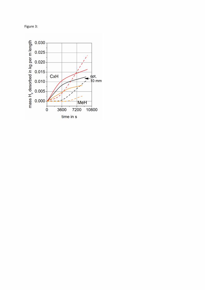
Figure 3:
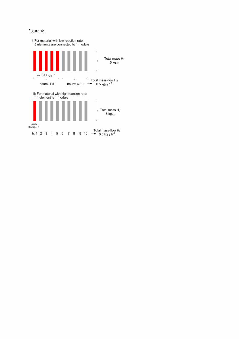
Figure 4:

Figure 5:

Figure 6:

Figure 7:
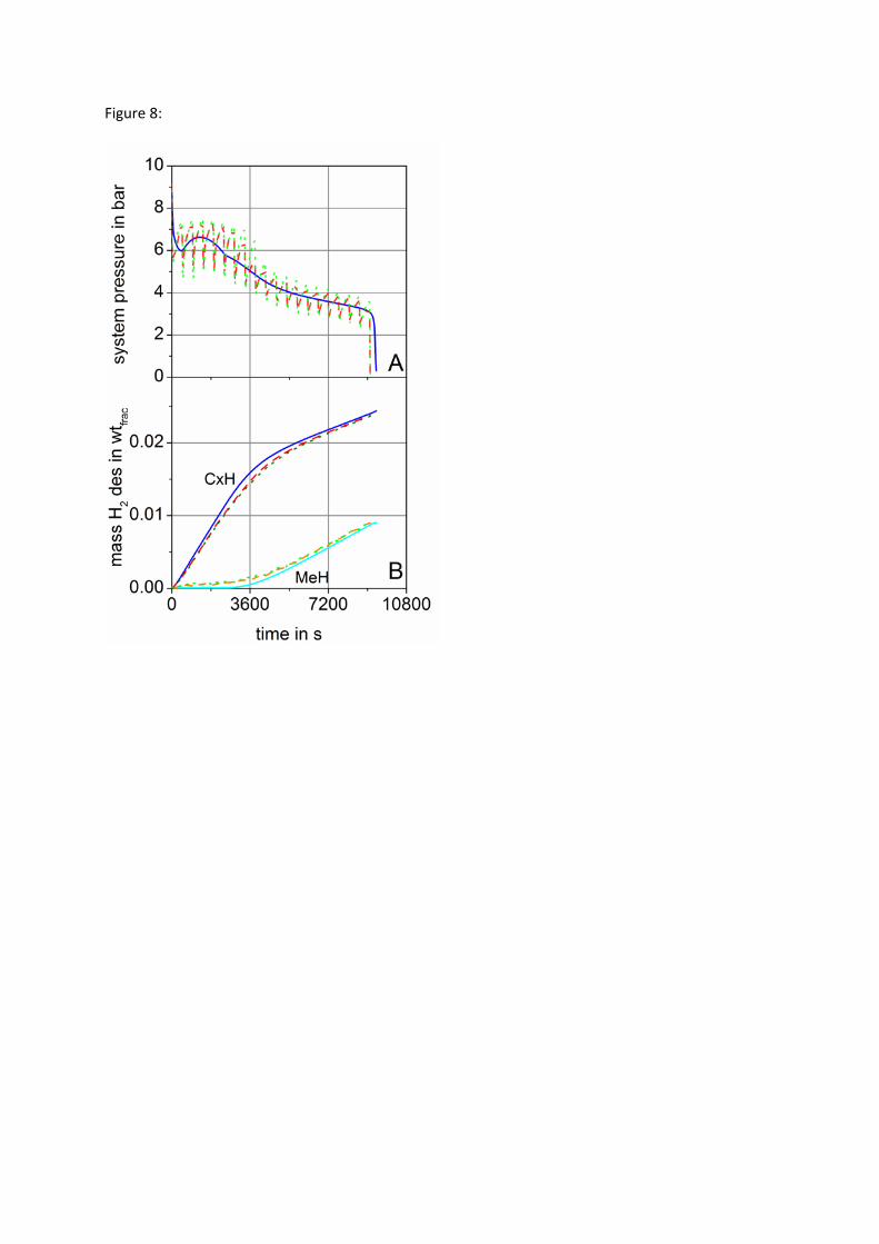
Figure 8:

Figure 9:

Figure 10: