Embed Size (px)
Citation preview
The electronic version is the official approved document. Verify this is the correct version before use.
CxP 70007
REVISION B, CHANGE 001National Aeronautics and Space Administration RELEASE DATE: JANUARY 7, 2008
CONSTELLATION DESIGN REFERENCE MISSIONS AND OPERATIONAL CONCEPTS
Downloaded from http://www.everyspec.com
Revision: B, Change 001 Document No: CxP 70007Release Date: 01/07/08 Page: 2 of 69Title: Constellation Design Reference Missions and Operational Concepts
REVISION AND HISTORY PAGE
Status Revision No.
Change No. Description Release
Date
Baseline - (The Baseline version of this document was not published in Windchill.)
09/14/06
Revision A Revision A (Reference CxCBD C000107/1-1, dated 1/24/07) (Includes post-SRR updates)
03/16/07
001 Change 001 (Reference CxCBD C000116/1-1, dated 5/24/07)
06/25/07
002 Change 002 (Reference CxCBD C000153/1-1, dated 6/20/07) Per Book Manager’s request, the Document Section was not renumbered to Section 2.0 as identified in the Directive.
07/23/07
B Revision B (Reference CxCBD 000202/1-1, dated 11/26/07)
11/28/07
001 Change 001 (Reference CxCBD 000216/3-1, dated 12/19/07) (No Change Bars are shown in this version, due to full DQA performed on this Change Package.)
01/07/08
NOTE: Updates to this document, as released by numbered changes (Change XXX), are identified by a black bar on the right margin.
Downloaded from http://www.everyspec.com
Revision: B, Change 001 Document No: CxP 70007Release Date: 01/07/08 Page: 3 of 69Title: Constellation Design Reference Missions and Operational Concepts
TABLE OF CONTENTS
PARAGRAPH PAGE
1.0 INTRODUCTION.............................................................................................. 8 1.1 PURPOSE........................................................................................................ 8 1.2 SCOPE............................................................................................................. 8 1.3 CHANGE AUTHORITY/RESPONSIBILITY ..................................................... 8 1.4 DOCUMENTS.................................................................................................. 9
1.4.1 Reference Documents ...................................................................... 9
2.0 SYSTEM OVERVIEW ...................................................................................... 9 2.1 SPACECRAFT................................................................................................. 11
2.1.1 Orion ................................................................................................. 11 2.1.2 Lander ............................................................................................... 11
2.2 LAUNCH VEHICLES........................................................................................ 11 2.2.1 Ares I................................................................................................. 11 2.2.2 Ares V ............................................................................................... 11
2.3 EARTH-BASED SUPPORT ............................................................................. 12 2.3.1 Mission Systems ............................................................................... 12 2.3.2 Ground Systems ............................................................................... 12
2.4 EVA SYSTEMS................................................................................................ 12 2.5 LUNAR SURFACE SYSTEMS (LSS) .............................................................. 12 2.6 PORTABLE EQUIPMENT................................................................................ 12
3.0 DESIGN REFERENCE MISSIONS.................................................................. 13 3.1 LUNAR DESIGN REFERENCE MISSIONS .................................................... 13
3.1.1 Lunar Sortie Crew DRM .................................................................... 13 3.1.2 Uncrewed Cargo Lander DRM.......................................................... 14 3.1.3 Visiting Lunar Outpost Expedition DRM............................................ 15 3.1.4 Resident Lunar Outpost Expedition DRM ......................................... 16 3.1.5 Outpost Remote Operations DRM .................................................... 17
3.2 ISS DESIGN REFERENCE MISSIONS........................................................... 17 3.2.1 ISS DRM ........................................................................................... 17
3.3 MARS DRM...................................................................................................... 18 3.4 TEST FLIGHTS................................................................................................ 19
Downloaded from http://www.everyspec.com
Revision: B, Change 001 Document No: CxP 70007Release Date: 01/07/08 Page: 4 of 69Title: Constellation Design Reference Missions and Operational Concepts
TABLE OF CONTENTS
PARAGRAPH PAGE
4.0 GENERAL OPERATIONAL CONCEPTS ........................................................ 20 4.1 SUPPORTABILITY AND SUSTAINABILITY.................................................... 20 4.2 OPERATIONS AND CAPABILITY ................................................................... 22 4.3 CREW SUPPORT............................................................................................ 24 4.4 INTEROPERABILITY....................................................................................... 26
5.0 OPERATIONS AND CAPABILITY BY PHASE ................................................ 27 5.1 PRODUCTION AND REFURBISHMENT ........................................................ 27 5.2 GROUND PROCESSING ................................................................................ 28
5.2.1 Standalone Operations ..................................................................... 28 5.2.2 Integration ......................................................................................... 31 5.2.3 Pad Operations ................................................................................. 32
5.3 LAUNCH .......................................................................................................... 33 5.3.1 Ares V/Lander ................................................................................... 34 5.3.2 Ares I/Orion ....................................................................................... 34
5.4 ASCENT........................................................................................................... 36 5.4.1 Ares V/Lander ................................................................................... 36 5.4.2 Ares I/Orion ....................................................................................... 36
5.5 LOW EARTH ORBIT (LEO) OPERATIONS..................................................... 37 5.5.1 LEO Configuration (Post Insertion) ................................................... 37 5.5.2 LEO Loiter ......................................................................................... 38 5.5.3 RPOD Operations (LEO)................................................................... 38 5.5.4 The Trans-Lunar Injection (TLI) Preparations Phase........................ 39
5.6 ISS OPERATIONS........................................................................................... 39 5.6.1 ISS Attached Operations................................................................... 39 5.6.2 ISS Departure ................................................................................... 40 5.6.3 ISS Deorbit........................................................................................ 40
5.7 LUNAR TRANSFER......................................................................................... 40 5.7.1 Trans-Lunar Cruise ........................................................................... 41 5.7.2 Lunar Orbit Insertion (LOI) Operations.............................................. 41
5.8 LUNAR OPERATIONS .................................................................................... 42 5.8.1 Pre-Surface Operations (LDO).......................................................... 42
Downloaded from http://www.everyspec.com
Revision: B, Change 001 Document No: CxP 70007Release Date: 01/07/08 Page: 5 of 69Title: Constellation Design Reference Missions and Operational Concepts
TABLE OF CONTENTS
PARAGRAPH PAGE 5.8.2 Lunar Lander Descent....................................................................... 42 5.8.3 Surface Operations ........................................................................... 43 5.8.4 Lunar Orbit Maintenance................................................................... 43 5.8.5 Lunar Ascent/RPOD Operations (LRO) ............................................ 44
5.9 EARTH TRANSFER......................................................................................... 45 5.9.1 Trans-Earth Injection (TEI) Operations ............................................. 45 5.9.2 Trans-Earth Cruise (TEC) ................................................................. 45 5.9.3 Earth Arrival Operations.................................................................... 46
5.10 RE-ENTRY/ENTRY OPERATIONS ................................................................. 46 5.10.1 CM Entry ........................................................................................... 46 5.10.2 Booster Re-Entry............................................................................... 47
5.11 DESCENT AND LANDING .............................................................................. 47 5.12 RECOVERY..................................................................................................... 48
5.12.1 CM Recovery .................................................................................... 48 5.12.2 Booster Recovery.............................................................................. 49
5.13 POST-FLIGHT PROCESSING ........................................................................ 49 5.14 REFURBISHMENT .......................................................................................... 50
5.14.1 CM Refurbishment (Trade) ............................................................... 50 5.14.2 Booster Refurbishment ..................................................................... 51
6.0 CONTINGENCY AND OFF-NOMINAL OPERATIONS.................................... 51 6.1 PAD CONTINGENCY CONCEPTS ................................................................. 51
6.1.1 PAD EMERGENCY EGRESS........................................................... 51 6.1.2 PAD ABORT ..................................................................................... 51 6.1.3 LAUNCH HOLD/SCRUB TURNAROUND ........................................ 51 6.1.4 EXTENDED SCRUB TURNAROUND .............................................. 52 6.1.5 EXTENDED STORAGE AFTER STACKING.................................... 52
6.2 ASCENT ABORTS........................................................................................... 53 6.2.1 Earth Ascent Abort ............................................................................ 53 6.2.2 Early Ascent Abort (Mode 1) ............................................................. 54 6.2.3 Mid-Ascent Abort (Mode 2) ............................................................... 54
Downloaded from http://www.everyspec.com

Revision: B, Change 001 Document No: CxP 70007Release Date: 01/07/08 Page: 6 of 69Title: Constellation Design Reference Missions and Operational Concepts
TABLE OF CONTENTS
PARAGRAPH PAGE 6.2.4 Late Ascent Abort (Mode 3) .............................................................. 55 6.2.5 Abort to Orbit (Mode 4) ..................................................................... 55
6.3 ABORT FROM LEO ......................................................................................... 56 6.3.1 Prior to Docking With Lander/EDS.................................................... 56 6.3.2 After Docking With Lander/EDS........................................................ 56
6.4 ABORT FROM TRANS-LUNAR ORBIT........................................................... 57 6.4.1 Incomplete TLI Burn.......................................................................... 57 6.4.2 Complete TLI Burn with Lunar Free-Return Trajectory ..................... 57 6.4.3 Complete TLI Burn Without Lunar Free-Return ................................ 58 6.4.4 Lander as a Lifeboat ......................................................................... 58
6.5 INCOMPLETE LOI MANEUVER...................................................................... 58 6.6 POST-LOI ABORTS......................................................................................... 58
6.6.1 Mission Termination Prior to Orion/Lander Separation ..................... 58 6.6.2 Mission Termination Post Orion/Lander Separation,
Prior to Descent ............................................................................ 59 6.7 LUNAR DESCENT ABORT ............................................................................. 59
6.7.1 Abort Between First Descent Burn and Powered Descent ............... 59 6.7.2 Powered Descent Abort .................................................................... 59
6.8 EARLY SURFACE MISSION TERMINATION ................................................. 59 6.9 LANDER ASCENT UNDERSPEED ................................................................. 60 6.10 TRANS-EARTH CRUISE CONTINGENCIES .................................................. 60 6.11 OFF NOMINAL RECOVERY ........................................................................... 61
6.11.1 Land Landing .................................................................................... 61 6.11.2 Water Landing................................................................................... 61 6.11.3 Ill or De-conditioned Crew Member................................................... 62
6.12 ISS CONTINGENCY OPERATIONS ............................................................... 62 6.13 CONTINGENCY EVA ...................................................................................... 63
6.13.1 ISS .................................................................................................... 63 6.13.2 Lunar ................................................................................................. 63
6.14 CABIN LEAK/DEPRESSURIZATION .............................................................. 63
Downloaded from http://www.everyspec.com
Revision: B, Change 001 Document No: CxP 70007Release Date: 01/07/08 Page: 7 of 69Title: Constellation Design Reference Missions and Operational Concepts
TABLE OF CONTENTS
APPENDIX PAGE A ACRONYMS AND ABBREVIATIONS AND GLOSSARY OF TERMS............ 65 B OPEN WORK................................................................................................... 69
TABLE B1-1 TO BE DETERMINED ITEMS.......................................................................... 69 B2-1 TO BE RESOLVED ISSUES............................................................................ 69
FIGURE 1 CONSTELLATION ARCHITECTURE HIERARCHY........................................ 10 2 LUNAR SORTIE CREW DRM ......................................................................... 14 3 UNCREWED CARGO LANDER DRM ............................................................. 15 4 LUNAR OUTPOST – CREW DRM .................................................................. 16 5 ISS DRM .......................................................................................................... 18 6 MARS DRM...................................................................................................... 19 7 CONSTELLATION PROGRAM MISSION PHASES........................................ 27
Downloaded from http://www.everyspec.com
Revision: B, Change 001 Document No: CxP 70007Release Date: 01/07/08 Page: 8 of 69Title: Constellation Design Reference Missions and Operational Concepts
1.0 INTRODUCTION
1.1 PURPOSE
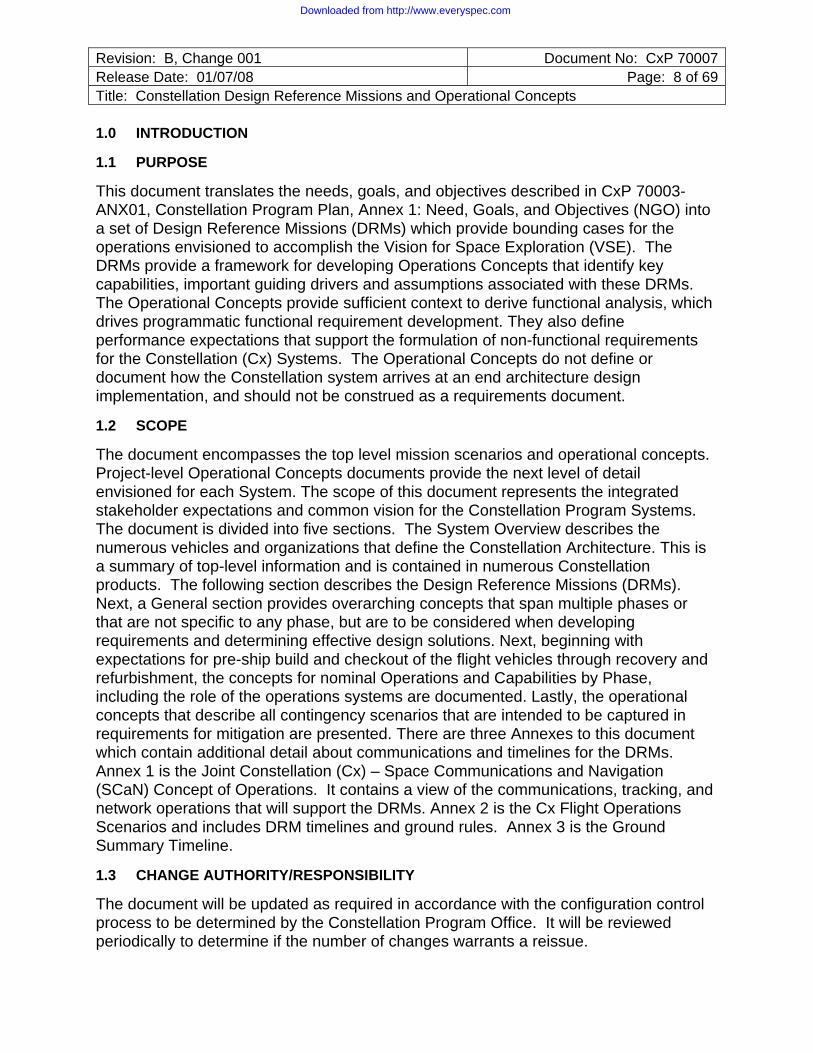
This document translates the needs, goals, and objectives described in CxP 70003-ANX01, Constellation Program Plan, Annex 1: Need, Goals, and Objectives (NGO) into a set of Design Reference Missions (DRMs) which provide bounding cases for the operations envisioned to accomplish the Vision for Space Exploration (VSE). The DRMs provide a framework for developing Operations Concepts that identify key capabilities, important guiding drivers and assumptions associated with these DRMs. The Operational Concepts provide sufficient context to derive functional analysis, which drives programmatic functional requirement development. They also define performance expectations that support the formulation of non-functional requirements for the Constellation (Cx) Systems. The Operational Concepts do not define or document how the Constellation system arrives at an end architecture design implementation, and should not be construed as a requirements document.
1.2 SCOPE
The document encompasses the top level mission scenarios and operational concepts. Project-level Operational Concepts documents provide the next level of detail envisioned for each System. The scope of this document represents the integrated stakeholder expectations and common vision for the Constellation Program Systems. The document is divided into five sections. The System Overview describes the numerous vehicles and organizations that define the Constellation Architecture. This is a summary of top-level information and is contained in numerous Constellation products. The following section describes the Design Reference Missions (DRMs). Next, a General section provides overarching concepts that span multiple phases or that are not specific to any phase, but are to be considered when developing requirements and determining effective design solutions. Next, beginning with expectations for pre-ship build and checkout of the flight vehicles through recovery and refurbishment, the concepts for nominal Operations and Capabilities by Phase, including the role of the operations systems are documented. Lastly, the operational concepts that describe all contingency scenarios that are intended to be captured in requirements for mitigation are presented. There are three Annexes to this document which contain additional detail about communications and timelines for the DRMs. Annex 1 is the Joint Constellation (Cx) – Space Communications and Navigation (SCaN) Concept of Operations. It contains a view of the communications, tracking, and network operations that will support the DRMs. Annex 2 is the Cx Flight Operations Scenarios and includes DRM timelines and ground rules. Annex 3 is the Ground Summary Timeline.
1.3 CHANGE AUTHORITY/RESPONSIBILITY
The document will be updated as required in accordance with the configuration control process to be determined by the Constellation Program Office. It will be reviewed periodically to determine if the number of changes warrants a reissue.
Downloaded from http://www.everyspec.com
Revision: B, Change 001 Document No: CxP 70007Release Date: 01/07/08 Page: 9 of 69Title: Constellation Design Reference Missions and Operational Concepts
1.4 DOCUMENTS
1.4.1 Reference Documents
The following documents contain supplemental information to guide the user in the application of this document.
CxP 70003-ANX01 Constellation Program Plan, Annex 1: Need, Goals, and Objectives
CxP 70085 (Baseline Pending)
Constellation Program Integrated Flight Test Strategy Document
2.0 SYSTEM OVERVIEW
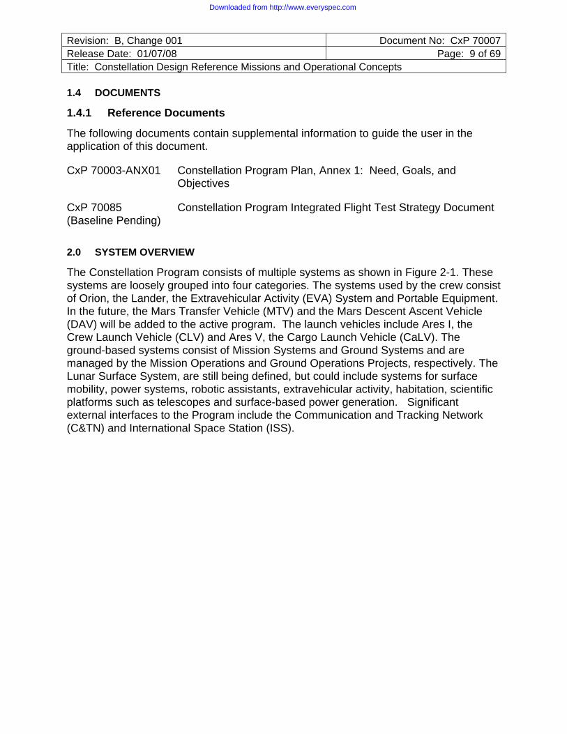
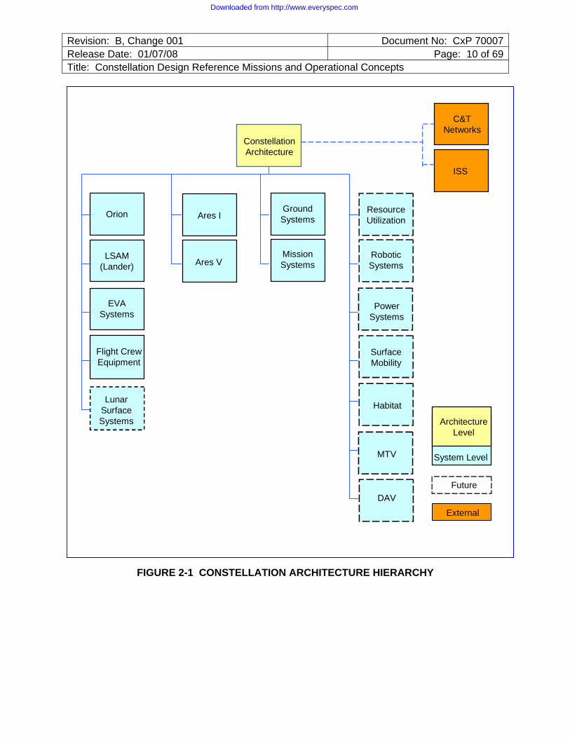
The Constellation Program consists of multiple systems as shown in Figure 2-1. These systems are loosely grouped into four categories. The systems used by the crew consist of Orion, the Lander, the Extravehicular Activity (EVA) System and Portable Equipment. In the future, the Mars Transfer Vehicle (MTV) and the Mars Descent Ascent Vehicle (DAV) will be added to the active program. The launch vehicles include Ares I, the Crew Launch Vehicle (CLV) and Ares V, the Cargo Launch Vehicle (CaLV). The ground-based systems consist of Mission Systems and Ground Systems and are managed by the Mission Operations and Ground Operations Projects, respectively. The Lunar Surface System, are still being defined, but could include systems for surface mobility, power systems, robotic assistants, extravehicular activity, habitation, scientific platforms such as telescopes and surface-based power generation. Significant external interfaces to the Program include the Communication and Tracking Network (C&TN) and International Space Station (ISS).
Downloaded from http://www.everyspec.com
Revision: B, Change 001 Document No: CxP 70007Release Date: 01/07/08 Page: 10 of 69Title: Constellation Design Reference Missions and Operational Concepts
Constellation Architecture
C&TNetworks
ISS
Ares VLSAM
(Lander)
EVASystems
Ares IOrion
MissionSystems
Ground Systems
RoboticSystems
ResourceUtilization
SurfaceMobility
PowerSystems
MTV
Habitat
DAV
Flight CrewEquipment
ArchitectureLevel
System Level
Future
External
Lunar Surface Systems
FIGURE 2-1 CONSTELLATION ARCHITECTURE HIERARCHY
Downloaded from http://www.everyspec.com
Revision: B, Change 001 Document No: CxP 70007Release Date: 01/07/08 Page: 11 of 69Title: Constellation Design Reference Missions and Operational Concepts
2.1 SPACECRAFT
2.1.1 Orion
The Orion System consists of a Crew Module (CM), a Service Module (SM), a Launch Abort System (LAS), and a Spacecraft Adapter (SA), and transports crew and cargo to orbit and back. The Orion System is used in all phases of the Constellation Program with the exception of the Cargo Lander DRM. Initially, the Orion transports crew and cargo to and from the ISS. It subsequently transports crew and cargo to and from a lunar orbit for short and extended duration missions. Orion may carry unpressurized cargo in an internal bay and/or via external attachment points. This cargo is accessible for removal from the Orion and transfer to the ISS. Finally, the Orion or a derivative supports missions to a Mars transfer vehicle, and then returns the crew and cargo to Earth after separation from this vehicle. There may be unique configurations to accommodate the needs of each defined DRM.
2.1.2 Lander
The Lander transports cargo to Low Lunar Orbit (LLO) and crew and cargo from LLO to the lunar surface and back. The Lander is only intended to support Lunar DRMs, but may be configured with or without crew. The uncrewed configuration transports significant cargo in support of extended Lunar Outpost missions and does not include an ascent capability from the lunar surface. The uncrewed/cargo version of the Lander, without ascent capability, may be used to store supplies or waste upon completion of its cargo delivery mission. The Lander is capable of using its descent stage to insert itself and Orion into LLO and carry crew or cargo to the lunar surface. For crewed Lunar Sortie configurations, the Lander serves as the crew’s home for up to seven days and uses an ascent stage to return them to LLO. The descent stage serves as the launch platform for the ascent stage and is left behind on the lunar surface. The ascent stage is jettisoned prior to Orion Trans-Earth Injection (TEI) from LLO.
2.2 LAUNCH VEHICLES
2.2.1 Ares I
Ares I is the launch vehicle for the Orion and delivers Orion into a mission-specific Ascent Target orbit. It consists of a 5-segment Solid Rocket Booster (SRB) first stage and a cryogenic liquid hydrogen/oxygen fueled upper stage consisting of a structural tank assembly and a J-2X engine. The first stage is reusable and the upper stage is expended after the Orion has separated during ascent.
2.2.2 Ares V
Ares V provides the heavy lift capability for the Constellation Program. Ares V consists of a 5-engine Core Stage, two 5-segment SRBs, and Earth Departure Stage (EDS), powered by a J-2X engine (same engine as the Ares I upper stage). For crewed lunar missions, the EDS serves as the Ares V third stage with a role in injecting the Lander/EDS stack into the Earth Rendezvous Orbit (ERO) where the Lander/EDS and
Downloaded from http://www.everyspec.com

Revision: B, Change 001 Document No: CxP 70007Release Date: 01/07/08 Page: 12 of 69Title: Constellation Design Reference Missions and Operational Concepts
Orion rendezvous and dock. The EDS performs the Trans-Lunar Injection (TLI) burn for the Lander and Orion after which it is jettisoned. For lunar cargo missions, EDS performs TLI directly, rather than going to a rendezvous orbit, and is then jettisoned during Trans-Lunar Cruise (TLC).
2.3 EARTH-BASED SUPPORT
2.3.1 Mission Systems
Mission Systems (MS) includes the facilities and resources that provide the operations infrastructure for mission planning with flight design; operations products including flight rules and procedures; crew and flight control team training; reconfiguration services; and flight operations of concurrent Constellation missions.
2.3.2 Ground Systems
Ground Systems (GS) consists of the facilities, facilities systems, Ground Support Equipment (GSE), manpower, hardware and software which are required to perform Ground Operations (GO). The GS element primarily resides at the launch site and provides the ground processing, integration, de-integration, integrated and interface testing, logistics services, and launch services for Orion/Ares I and the Ares V/EDS/ Lander. GS also provides post-landing and recovery services for the Orion Crew Module, including Search and Rescue (SAR) and supports Orion refurbishment and maintenance, if required. In addition, post-landing and recovery services for the Ares I First Stage and Ares V SRBs are provided by GS.
2.4 EVA SYSTEMS
The EVA System includes the elements necessary to protect crewmembers and allow them to work effectively in the pressure and thermal environments that exceed the human capability during all mission phases. The EVA System includes the pressure suits, EVA life support systems, umbilicals, EVA tools and mobility aids, EVA-specific vehicle interfaces, EVA servicing equipment, suit avionics, individual crew survival equipment (i.e. integral to the pressure suit), and ground support equipment.
2.5 LUNAR SURFACE SYSTEMS (LSS)
As system requirements for Lunar Surface Systems (LSS) are developed, they will be addressed in future versions of this document.
2.6 PORTABLE EQUIPMENT
Portable Equipment includes the various Intravehicular Activity (IVA) tools and other portable equipment used to support crew operations, maintenance, and other activities throughout the mission. Examples include screwdrivers, wrenches, hammers, crew translation aids and restraints, first-aid kits, portable medical equipment, laptop computers, Digital Video Disk (DVD) players, food, clothing, hygiene provisions, and cameras. Portable Equipment also provides crew survival equipment that is not integral to the suit (i.e., crew survival kit, life raft).
Downloaded from http://www.everyspec.com
Revision: B, Change 001 Document No: CxP 70007Release Date: 01/07/08 Page: 13 of 69Title: Constellation Design Reference Missions and Operational Concepts
3.0 DESIGN REFERENCE MISSIONS
3.1 LUNAR DESIGN REFERENCE MISSIONS
3.1.1 Lunar Sortie Crew DRM
Lunar Sortie missions are representative of missions that enable up to four crewmembers to explore a single site anywhere on the Moon with the length of stay limited by the amount of consumables brought by the Lander and Delta-V margins.
This type of mission is accomplished independent of pre-positioned lunar surface infrastructure such as habitats or power stations. A Lunar Sortie mission may occur at any time during the Constellation Program Lunar Campaign. The Lunar Sortie mission allows for exploration of high-interest science sites, scouting of future Lunar Outpost locations, or other technology development objectives within the capabilities of the available lunar surface infrastructure. During a sortie, the crew has the capability to perform daily EVAs.
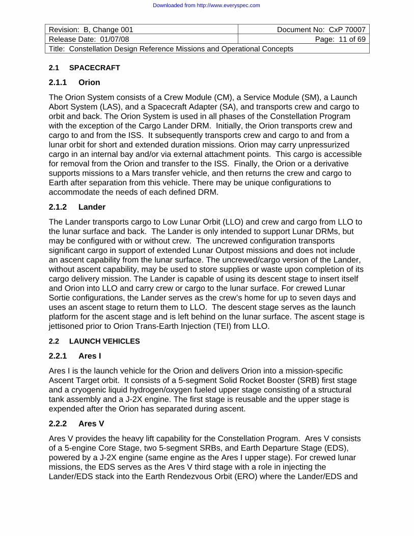
A Lunar Sortie mission utilizes the following systems for a mission: Ares I, Orion, Ares V, Lander, MS, Ground Systems (GS), EVA and Portable Equipment. The ascent mission mode for the Lunar Sortie mission is a combination Earth Orbit Rendezvous and Lunar Orbit Rendezvous (EOR-LOR) architecture. The Lander/EDS is inserted into ERO with a single Ares V launch followed within 90 minutes by an Ares I launch of the crew and cargo aboard the Orion. Orion and Lander/EDS then rendezvous and dock in ERO. The crew may enter the Lander prior to Trans-Lunar Injection/Lunar Orbit Insertion (TLI/LOI). The EDS performs the TLI burn for the Lander and Orion and then separates from the stack. The EDS maneuvers to target for a safe disposal away from the Orion/Lander path or any future spacecraft missions. The Lander performs any required mid-course correction maneuvers during the trans-lunar cruise. Upon reaching the Moon, the Lander then performs the LOI for the two mated elements.
Figure 3.1.1-1 illustrates the Lunar Sortie Crew mission. Although this DRM represents the current baseline Lunar Sortie mission, the architecture developed to support this DRM should not preclude the capability to accomplish a Lunar Sortie with a single launch of both crew and cargo on the Ares V.
Downloaded from http://www.everyspec.com
Revision: B, Change 001 Document No: CxP 70007Release Date: 01/07/08 Page: 14 of 69Title: Constellation Design Reference Missions and Operational Concepts
Ascent Stage Expended
ED
S, L
AN
DE
R
CE
VEarth Departure Stage Expended
LANDER Performs LOI
MOON
EARTH
100 km Low Lunar Orbit
Landing
ERO
Vehicles Not to Scale
Ascent Stage Expended
ED
S, L
AN
DE
R
CE
VEarth Departure Stage Expended
LANDER Performs LOI
MOON
EARTH
100 km Low Lunar Orbit
Landing
ERO
Vehicles Not to Scale
FIGURE 3.1.1-1 LUNAR SORTIE CREW DRM
3.1.2 Uncrewed Cargo Lander DRM
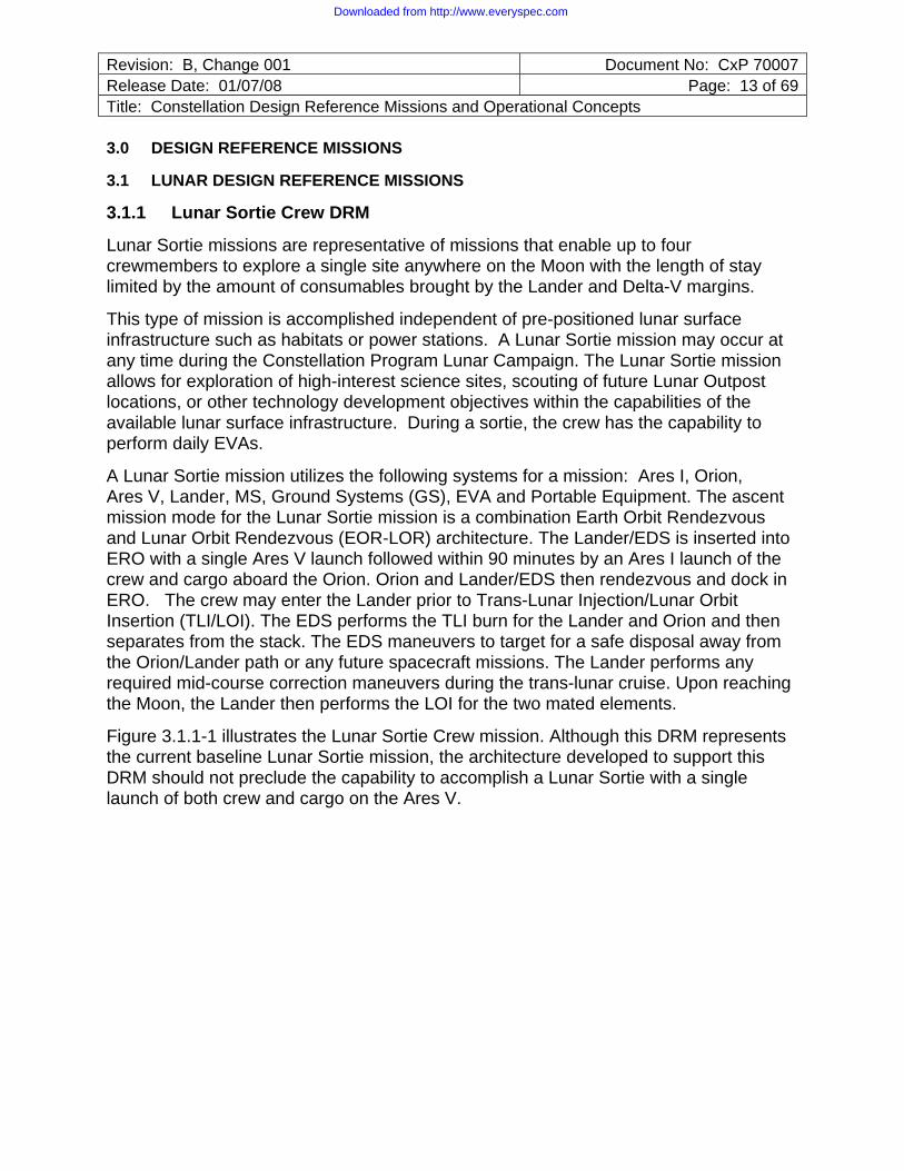
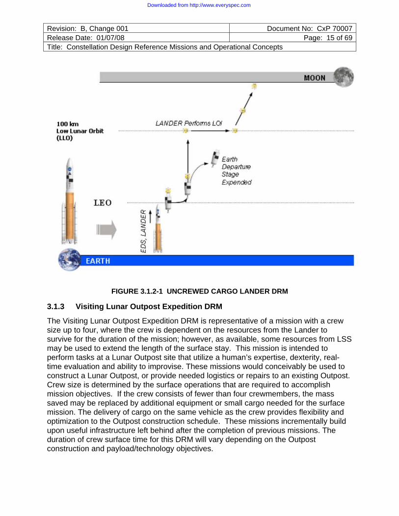
The Uncrewed Cargo Lander DRM is representative of uncrewed missions that deliver significant cargo to any designated location on the lunar surface in a single mission. This capability is used to deliver surface infrastructure needed for Lunar Outpost construction, and to provide periodic logistics resupply to support a continuous human lunar presence. Cargo delivery may be several modular elements or a single, large or heavy element.
An Uncrewed Cargo Lander mission utilizes the following systems for a mission: Ares V, Lander, MS, and GS. The mission mode for the Lunar Outpost mission is a direct insertion to lunar orbit architecture. The Lander is launched on Ares V into near Lunar Rendezvous Orbit (LRO); however, this does not preclude a Low Earth Orbit (LEO) loiter prior to TLI. The Lander completes the lunar orbit insertion. After some period of time the Lander will autonomously descends to the surface and lands at a designated target, presumably in proximity to an Outpost location. This mission ends at touchdown on the lunar surface. Figure 3.1.2-1 illustrates the Uncrewed Cargo Lander mission.
Downloaded from http://www.everyspec.com
Revision: B, Change 001 Document No: CxP 70007Release Date: 01/07/08 Page: 15 of 69Title: Constellation Design Reference Missions and Operational Concepts
FIGURE 3.1.2-1 UNCREWED CARGO LANDER DRM
3.1.3 Visiting Lunar Outpost Expedition DRM
The Visiting Lunar Outpost Expedition DRM is representative of a mission with a crew size up to four, where the crew is dependent on the resources from the Lander to survive for the duration of the mission; however, as available, some resources from LSS may be used to extend the length of the surface stay. This mission is intended to perform tasks at a Lunar Outpost site that utilize a human’s expertise, dexterity, real-time evaluation and ability to improvise. These missions would conceivably be used to construct a Lunar Outpost, or provide needed logistics or repairs to an existing Outpost. Crew size is determined by the surface operations that are required to accomplish mission objectives. If the crew consists of fewer than four crewmembers, the mass saved may be replaced by additional equipment or small cargo needed for the surface mission. The delivery of cargo on the same vehicle as the crew provides flexibility and optimization to the Outpost construction schedule. These missions incrementally build upon useful infrastructure left behind after the completion of previous missions. The duration of crew surface time for this DRM will vary depending on the Outpost construction and payload/technology objectives.
Downloaded from http://www.everyspec.com
Revision: B, Change 001 Document No: CxP 70007Release Date: 01/07/08 Page: 16 of 69Title: Constellation Design Reference Missions and Operational Concepts
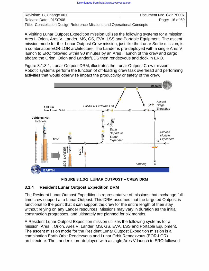
A Visiting Lunar Outpost Expedition mission utilizes the following systems for a mission: Ares I, Orion, Ares V, Lander, MS, GS, EVA, LSS and Portable Equipment. The ascent mission mode for the Lunar Outpost Crew mission, just like the Lunar Sortie mission, is a combination EOR-LOR architecture. The Lander is pre-deployed with a single Ares V launch to ERO followed within 90 minutes by an Ares I launch of the crew and cargo aboard the Orion. Orion and Lander/EDS then rendezvous and dock in ERO.
Figure 3.1.3-1, Lunar Outpost DRM, illustrates the Lunar Outpost Crew mission. Robotic systems perform the function of off-loading crew task overhead and performing activities that would otherwise impact the productivity or safety of the crew.
Ascent Stage Expended
ED
S, L
AN
DE
R
CE
V
Earth Departure Stage Expended
LANDER Performs LOI
MOON
EARTH
100 km Low Lunar Orbit
Landing
Service Module ExpendedERO
Vehicles Not to Scale
FIGURE 3.1.3-1 LUNAR OUTPOST – CREW DRM
3.1.4 Resident Lunar Outpost Expedition DRM
The Resident Lunar Outpost Expedition is representative of missions that exchange full-time crew support at a Lunar Outpost. This DRM assumes that the targeted Outpost is functional to the point that it can support the crew for the entire length of their stay without relying on any Lander resources. Missions may vary in duration as the initial construction progresses, and ultimately are planned for six months.
A Resident Lunar Outpost Expedition mission utilizes the following systems for a mission: Ares I, Orion, Ares V, Lander, MS, GS, EVA, LSS and Portable Equipment. The ascent mission mode for the Resident Lunar Outpost Expedition mission is a combination Earth Orbit Rendezvous and Lunar Orbit Rendezvous (EOR-LOR) architecture. The Lander is pre-deployed with a single Ares V launch to ERO followed
Downloaded from http://www.everyspec.com
Revision: B, Change 001 Document No: CxP 70007Release Date: 01/07/08 Page: 17 of 69Title: Constellation Design Reference Missions and Operational Concepts
within 90 minutes by an Ares I launch of the crew and cargo aboard the Orion. Orion and Lander/EDS then rendezvous and dock in ERO.
A primary objective of the Constellation Program is to establish a sustained human presence on the lunar surface. This mission is intended to realize the goal of developing technology, scientific knowledge and operational experience for future human missions to Mars. The Resident Lunar Outpost Expedition DRM transports crew and cargo repeatedly to one selected site and sustains human presence on the Lunar Outpost for as long as necessary to fill the gap between replacement crews. The accompanying cargo consists of resupply logistics which cannot be produced on the Moon in-situ, and replacement hardware which cannot be repaired in-place. Activities performed during the mission support sustaining operations and payload/technology objectives. The crew performs frequent EVAs to accomplish scientific and operational activities and uses long-range mobility systems to traverse and transport cargo beyond the local vicinity. Robotic systems perform the function of off-loading crew task overhead and performing activities that would otherwise impact the productivity or safety of the crew.
3.1.5 Outpost Remote Operations DRM
Outpost Remote Operations missions are defined by those operations that are performed without direct interface with the crew, and applies any time during the lunar campaign when crew is not present. This DRM is also applicable while the crew is on the lunar surface if the activities have no crew interface. This DRM contains only a Surface Ops phase. An Outpost Remote Operations DRM utilizes the following systems for a mission: Lander, MS, LSS and Portable Equipment. The intent of this DRM is to encompass the events on the surface of the Moon which continue to operate when the flight which brought the systems there departs the lunar surface, the crew that installed them is no longer involved, or continuous upgrades create a collection of hardware from multiple flights. This DRM could include uncrewed operations of robotics, autonomous operation of In-Situ Resource Utilization (ISRU) plants, construction tasks tele-robotically controlled from Earth or a variety of remotely commanded systems. Initially, Mission Systems provides the primary command function for remote operations; however, autonomous Lunar Surface Systems must progressively play a more significant goal when looking ahead to Mars mission capability.
3.2 ISS DESIGN REFERENCE MISSIONS
3.2.1 ISS DRM
The ISS DRM supports ISS increment crew rotation and resupply of the ISS. ISS missions provide a proving ground for Constellations systems while at the same time providing an alternate resource for the support of ISS crewed operations. The presence of a quiescent Orion at the ISS should be included and that the existing ISS crew returns to Earth in the Orion that brought them to the ISS, not in the Orion that brings the replacement crew.
Downloaded from http://www.everyspec.com
Revision: B, Change 001 Document No: CxP 70007Release Date: 01/07/08 Page: 18 of 69Title: Constellation Design Reference Missions and Operational Concepts
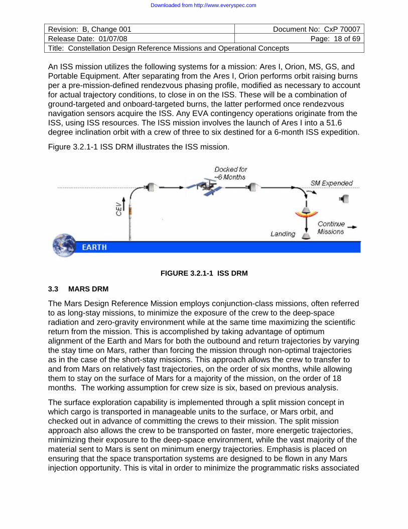
An ISS mission utilizes the following systems for a mission: Ares I, Orion, MS, GS, and Portable Equipment. After separating from the Ares I, Orion performs orbit raising burns per a pre-mission-defined rendezvous phasing profile, modified as necessary to account for actual trajectory conditions, to close in on the ISS. These will be a combination of ground-targeted and onboard-targeted burns, the latter performed once rendezvous navigation sensors acquire the ISS. Any EVA contingency operations originate from the ISS, using ISS resources. The ISS mission involves the launch of Ares I into a 51.6 degree inclination orbit with a crew of three to six destined for a 6-month ISS expedition.
Figure 3.2.1-1 ISS DRM illustrates the ISS mission.
FIGURE 3.2.1-1 ISS DRM
3.3 MARS DRM
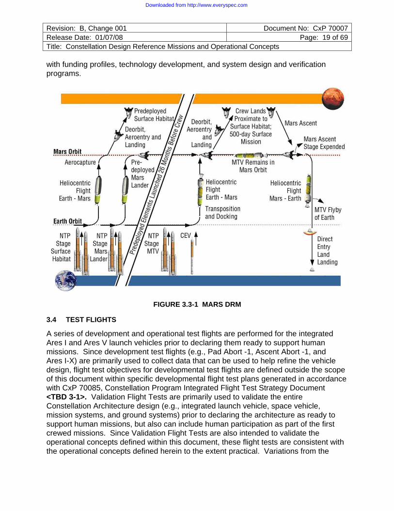
The Mars Design Reference Mission employs conjunction-class missions, often referred to as long-stay missions, to minimize the exposure of the crew to the deep-space radiation and zero-gravity environment while at the same time maximizing the scientific return from the mission. This is accomplished by taking advantage of optimum alignment of the Earth and Mars for both the outbound and return trajectories by varying the stay time on Mars, rather than forcing the mission through non-optimal trajectories as in the case of the short-stay missions. This approach allows the crew to transfer to and from Mars on relatively fast trajectories, on the order of six months, while allowing them to stay on the surface of Mars for a majority of the mission, on the order of 18 months. The working assumption for crew size is six, based on previous analysis.
The surface exploration capability is implemented through a split mission concept in which cargo is transported in manageable units to the surface, or Mars orbit, and checked out in advance of committing the crews to their mission. The split mission approach also allows the crew to be transported on faster, more energetic trajectories, minimizing their exposure to the deep-space environment, while the vast majority of the material sent to Mars is sent on minimum energy trajectories. Emphasis is placed on ensuring that the space transportation systems are designed to be flown in any Mars injection opportunity. This is vital in order to minimize the programmatic risks associated
Downloaded from http://www.everyspec.com
Revision: B, Change 001 Document No: CxP 70007Release Date: 01/07/08 Page: 19 of 69Title: Constellation Design Reference Missions and Operational Concepts
with funding profiles, technology development, and system design and verification programs.
FIGURE 3.3-1 MARS DRM
3.4 TEST FLIGHTS
A series of development and operational test flights are performed for the integrated Ares I and Ares V launch vehicles prior to declaring them ready to support human missions. Since development test flights (e.g., Pad Abort -1, Ascent Abort -1, and Ares I-X) are primarily used to collect data that can be used to help refine the vehicle design, flight test objectives for developmental test flights are defined outside the scope of this document within specific developmental flight test plans generated in accordance with CxP 70085, Constellation Program Integrated Flight Test Strategy Document <TBD 3-1>. Validation Flight Tests are primarily used to validate the entire Constellation Architecture design (e.g., integrated launch vehicle, space vehicle, mission systems, and ground systems) prior to declaring the architecture as ready to support human missions, but also can include human participation as part of the first crewed missions. Since Validation Flight Tests are also intended to validate the operational concepts defined within this document, these flight tests are consistent with the operational concepts defined herein to the extent practical. Variations from the
Downloaded from http://www.everyspec.com

Revision: B, Change 001 Document No: CxP 70007Release Date: 01/07/08 Page: 20 of 69Title: Constellation Design Reference Missions and Operational Concepts
operational concepts defined herein are addressed in the specific flight test plans developed in accordance with CxP 70085 <TBD 3-1>.
4.0 GENERAL OPERATIONAL CONCEPTS
The following section describes operational guidelines, constraints and capabilities that span multiple phases or those that are not directly applicable to a specific phase. These concepts are intended to provide an overall philosophy that guides development of Constellation Program requirements.
4.1 SUPPORTABILITY AND SUSTAINABILITY
4.1.1 Use of common consumable items such as batteries, waste management supplies, filters, within and across vehicles and habitats to the greatest extent practical, allows interchangeability, simplifies maintenance and minimizes the number of spares needed. This reduces logistics costs and complexity. Similarly, this applies to hardware that can be used to effect a repair at all levels.
4.1.2 Constellation Systems enable and facilitate maintenance at the lowest practical hardware level by repair of failed items or, if necessitated by operational constraints, replacement with a spare at the lowest possible hardware level.
4.1.3 Direct access to Line-Replaceable Units (LRUs) is highly preferred. Accessibility is a key parameter in hardware and design. The ability to reprogram devices and update software is needed for efficient maintainability. Software updates are performed both to correct latent defects as well as adapt to changing mission needs. Cost and schedule impacts are reduced and potential equipment damage is avoided when software updates can be performed without requiring LRU removal or disassembly.
4.1.4 Pre-maintenance hazard isolation is limited to the item being maintained and all hardware that is impacted during that maintenance. The impact of maintenance is minimized as much as possible to other systems (e.g., for replacement of an LRU, the design minimizes the number of LRUs that have to be removed, powered down, cables moved, connectors disconnected).
4.1.5 Consolidated and centralized interfaces, for both flight and ground personnel, such as umbilical connection points along one side of the integrated launch vehicle while on the pad, or grouping access points around the vehicle during integration and test activities, are used to minimize the number of service points whenever feasible while maintaining compliance with design requirements regarding separation of critical functions. Limited intrusive access is necessary to avoid significant platform development and maintenance. Hardware accessibility and operational procedures minimize opportunity for damage by personnel during assembly, maintenance, and servicing activities.
4.1.6 Element subsystem and component complexity and the amount of interdependence on other systems are minimized to ease operations and maintenance
Downloaded from http://www.everyspec.com
Revision: B, Change 001 Document No: CxP 70007Release Date: 01/07/08 Page: 21 of 69Title: Constellation Design Reference Missions and Operational Concepts
by the crew and ground personnel. Flight subsystems operate during ground processing with limited dependence on specialized Ground Support Equipment (GSE). System software complexity and interdependence of software components are minimized to achieve the least impact to related components when data or software is modified. Verification requirements are minimized as a result.
4.1.7 The impact of software updates to dependent systems is minimized. For example, during replacement of software in a given computer, flight- and mission-critical sub-systems ‘down-stream’ of that computer are capable of operating without direct control or insight, and are not impacted by the functions required by the computer to prepare for, or recover from the update.
4.1.8 Optimally, preventive and corrective in-space maintenance is performed as an Intravehicular Activity (IVA) during transit and on the extraterrestrial surface.
4.1.9 Health and status including fault/failure detection, voice, and command information is exchanged among Constellation elements and the International Space Station (ISS) as appropriate to the mission phases in order to facilitate informed mission operations decisions by Ground Systems, Missions Systems, and Crew.
4.1.10 Automated isolation of failures to the repairable level or operable system reduces troubleshooting effort by flight crew and ground personnel. This expedites maintenance and repair operations and facilitates failure response determination and reconfiguration by crew, flight control, and ground personnel. This capability results in less usage of test equipment, reduces test and repair times, and minimizes training requirements for operators. Automated failure isolation facilitates looking for common cause failures before committing to the next launch or major operation phase. Isolation is such that failure, immediate impacts, and recommended response actions (or actions the architecture may be performing automatically) are clearly defined to vehicle operators. Ancillary information resulting from the primary failure is presented so as not to mask the source fault or important impact/response information. The failure isolation is useful during each mission phase from ground processing, through launch, in-flight operations, landing and post-flight analysis.
To maintain maximum situational awareness and crew/vehicle safety, failure isolation is initially focused at an operable level, i.e., keyed to the immediate impacts and actions required by the vehicle. Further troubleshooting (e.g., Built-in Test [BIT]) with more detailed root cause diagnoses is performed when operationally feasible.
4.1.11 As the program matures, methods and technologies to replenish consumables and expendables in-situ are developed, when practicable, to reduce the cargo delivery mass necessary for longer and longer mission durations.
4.1.12 Flight systems survive the natural environment of the launch pad from roll out to the pad through consecutive launch attempts without the use of remove-before-flight weather protective covers or enclosures to reduce pad access.
Downloaded from http://www.everyspec.com
Revision: B, Change 001 Document No: CxP 70007Release Date: 01/07/08 Page: 22 of 69Title: Constellation Design Reference Missions and Operational Concepts
4.1.13 Primary use of space-based assets for navigation and communication relay reduce investment to upgrade and/or maintain ground sites. This enables streamlined operations and reduced life cycle costs for the Constellation Program.
4.1.14 An integrated work control system is used during the ground processing, testing, troubleshooting, resolving of hardware problems, and launching of Constellation flight hardware.
4.1.15 Standardized means of identifying cargo are used by all flight Systems.
4.1.16 Flight Systems and LSS protect for impacts due to the space environment.
4.2 OPERATIONS AND CAPABILITY
4.2.1 Both the crew and the Mission Operations may independently perform all functions required to protect the crew and to ensure their successful return to Earth. Sensors and software algorithms enable the crew using onboard systems to be prime for such functions as determining abort boundaries, targeting burns, and budgeting consumables. A robust onboard integrated system automatically detects and responds to any single mission critical failure limiting time-critical actions by crew or ground controllers. Reliance on the automatic system as the primary means of safing the vehicle only occurs when the Orion is in a quiescent flight phase and uncrewed. Safety-critical failure scenarios are handled primarily via vehicle automation without rapid response from crew or ground controllers. Autonomy in all aspects of mission requirements is desired when technologically and financially feasible to provide operational capabilities and experience that will be required for Mars missions.
4.2.2 When the crew is in Orion, the Orion can return the crew to Earth without the ability to communicate with the ground during all relevant mission phases. When the crew is in the Lander, the Lander can return the crew to the Orion without the ability to communicate with the ground during all relevant mission phases.
4.2.3 Systems transmit, receive and appropriately respond to commands between systems.
4.2.4 While mated, Constellation flight elements such as the Ares I, Ares V, Orion and Lander use their respective independent Guidance, Navigation, and Control (GN&C) systems to monitor trajectory control performance.
4.2.5 When under manual control, attitude control systems provide acceptable vehicle handling characteristics in accordance with accepted standards during all mission phases, resulting in less complex training and procedures. For example, cross-coupling is minimized for nominal and contingency scenarios.
4.2.6 Earth return aborts are available at any time during the ISS DRM. For the Lunar Sortie DRM, the Orion has sufficient capability to execute an abort during Trans- Lunar Coast. It can also perform the necessary orbital adjustments (inclination and node) to facilitate an in-plane ascent of the Lander. This creates the capability for abort from the surface at any time during Lunar Sortie missions. For Lunar Outpost Missions,
Downloaded from http://www.everyspec.com

Revision: B, Change 001 Document No: CxP 70007Release Date: 01/07/08 Page: 23 of 69Title: Constellation Design Reference Missions and Operational Concepts
the orbital adjustment requirements for co-planar anytime ascent will exceed the capabilities of Orion. The frequency of lunar Outpost abort opportunities will depend upon the timing of the abort with respect to the orbit of the Orion and the location of the Outpost. Thus, a combination of ascent aborts and safe haven capability at the Outpost will be used. At the end of the lunar phase of the mission, the Orion has the capability to adjust its orbit for proper return to Earth. Mars abort capabilities are yet to be defined.
4.2.7 The crew can be safely returned to Earth from any point in a lunar mission (including from the lunar surface), even if Orion is depressurized.
4.2.8 When communication opportunities exist, Mission Operations can perform critical vehicle functions without requiring crew intervention. This supports uncrewed vehicle operations for mission safety and success.
4.2.9 Bi-directional file transfer occurs between crewed Systems. Files are of arbitrary content and length appropriate to the purpose.
4.2.10 Flight products development is a continuous effort to support current and future missions.
4.2.11 Mission configuration products are utilized by Constellation Systems during flight to select or change telemetry formats appropriate for a specific flight phase, even while similar products are used by Constellation Systems on the ground to enable them to accept, process and distribute the changed telemetry format.
4.2.12 Crew, flight controller and mission management training enables successful conduct of flight operations for individual, multiple and concurrent Constellation missions.
4.2.13 Mission Operations monitors vehicle telemetry and processes radiometric tracking data in order to perform navigation for the spacecraft systems during all mission phases. Mission Operations provides state vector updates to the vehicles during periods when the ground navigation capability exceeds that of the onboard systems. Tracking data is provided to Mission Operations by external interfaces (e.g. Communications and Tracking Network).
4.2.14 The Mission Operations System plans and computes maneuvers for each vehicle for all phases of flight. Each vehicle independently computes maneuvers and/or receives the ground-computed maneuver, depending on the mission phase.
4.2.15 The Orion or Lander automatically performs vehicle control and system reconfigurations to the maximum extent possible. Manual crew intervention capability also is provided. System design ensures the crew knows when manual intervention is possible, and informs the crew when and what system reconfigurations have been performed. When manual takeover of time-critical tasks is required, the crew has immediate access to necessary data and controls.
4.2.16 An electronic procedures system operates in conjunction with the health and status system of the crewed elements (e.g. Orion, lunar habitat) to provide rapid access
Downloaded from http://www.everyspec.com
Revision: B, Change 001 Document No: CxP 70007Release Date: 01/07/08 Page: 24 of 69Title: Constellation Design Reference Missions and Operational Concepts
to nominal and off-nominal procedures. Electronic procedures are tailored by mission phase and malfunction root cause to support autonomous crew and vehicle operations to the maximum extent possible.
4.2.17 Flight systems operate in planned mission attitudes and survive excursion (any attitude outside of the planned mission attitude) without the need for real-time attitude analysis or recertification. The vehicle continues nominal mission operations in any attitude without hardware damage. As operations mature, flight systems autonomously track and manage constraints related to vehicle attitude (e.g., communications coverage, power generation, thermal environment constraints, and structural integrity), and resource utilization and consumables (power, propellant, and atmosphere constituents) and resolve conflicts and respond to detected consumables leaks.
4.2.18 Constellation Systems may perform concurrent and dissimilar missions. For example, simultaneous ISS and Lunar Outpost missions.
4.2.19 Engineering support for flight systems is provided throughout all mission phases to ensure Ground Systems and Mission Systems manage operations effectively.
4.2.20 Constellation systems should significantly reduced ground processing time, use less manpower, and feature increased launch availability over legacy manned spaceflight systems. Reductions in ground processing and increased launch availability are accomplished by the infusion of technology, simplification of the flight hardware, and streamlining of ground operations and sustaining engineering processes.
4.2.21 Still and motion imagery is used for flight configuration documentation, engineering analysis, anomaly resolution, communications (Public Affairs Office [PAO]), work documentation, training and education, quality assurance and verification, historical documentation, to establish a baseline configuration prior to flight, for security, and mishap reconstruction. Imagery is managed at the Program level via an integrated imagery management system that utilizes a central access portal. Imagery data acquired at any NASA center, or contractor facility, or during any phase of flight or ground activity is available to the entire program at any program location via this central access portal. All Constellation imagery is processed as required, collected, catalogued, archived and distributed to the appropriate flight or project facilities.
4.2.22 Still and motion imagery of flight systems is captured during all mission phases with sufficient quality to be useful for analysis (comparison) and operations as necessary. This imagery is transmitted to Mission Systems in real-time or near real-time. The imagery and the integrated imagery management system that houses it assure configuration control. Baseline configuration imagery collected during all phases leading up to flight provides critical reference material to evaluate in-flight anomalies.
4.3 CREW SUPPORT
4.3.1 The crewed configuration of Orion can be flown with a crew size from zero to six crew members. A zero crew capability is used for the early test flights to reduce risk to the crew for future crewed missions and verify the operation of the vehicle systems
Downloaded from http://www.everyspec.com
Revision: B, Change 001 Document No: CxP 70007Release Date: 01/07/08 Page: 25 of 69Title: Constellation Design Reference Missions and Operational Concepts
for crew and cargo missions. The one or two crew person scenario covers the case where the number of crew coming down from ISS is larger than the number of crew going up (others being delivered via Soyuz or the Commercial capability). The normal crew contingent for Orion ISS missions is three where the crew travels to and from ISS on the same Orion. Larger crew contingents of four to six may be flown where up to three remain on-orbit for a long duration mission and the rest return with the "relieved" ISS crew. In this case, these additional crew return in the Orion already on-orbit. Lunar missions fly four crew.
4.3.2 Private conferences between the crew and the ground occur as required, but at least weekly. The behavioral well-being of the crew is monitored and supported by Mission Operations personnel.
4.3.3 Any time a human is in the loop, the system enables the maximum effectiveness of the crew and operations personnel and minimizes the risk or opportunity for human error.
4.3.4 The crewed flight elements provide a pressurized, temperature and humidity controlled atmosphere for the crew during all nominal phases of flight.
4.3.5 Depressurization and operation of hatches may be accomplished from either side by a single member of the crew without tools.
4.3.6 Medical supplies are available in all crew-inhabited systems. Advanced life support/health care equipment allocated to ISS or lunar surface operations is stowed in the ISS or Lander, as applicable, and is brought into Orion only in case of a need to transport an ill or injured member of the crew back to Earth. Orion accommodates this equipment (power, data, oxygen, volume, and structure) while docked to the Lander and during return, reentry and landing.
4.3.7 The inhabited element cabin provides an environment that minimizes health risks from acoustic noise, poor air or water quality, hazardous materials, microbiological contamination, and radiation.
4.3.8 The crew can override automated systems and manually control the spacecraft attitude and trajectory when it is possible to provide additional margin for mission success and crew safety.
4.3.9 For Lunar and Mars missions when the crew is exposed to long periods of gravity < 1-g for more than eight consecutive days, exercise countermeasures are available to the crew. For Orion missions to ISS, exercise on Orion is not necessary.
4.3.10 Support and facilities exist that provide the crew returning from spaceflight a means of readjusting back to pre-flight baseline health and status conditions and preparing for subsequent assessment and future missions.
Downloaded from http://www.everyspec.com
Revision: B, Change 001 Document No: CxP 70007Release Date: 01/07/08 Page: 26 of 69Title: Constellation Design Reference Missions and Operational Concepts
4.4 INTEROPERABILITY
4.4.1 Interoperability is optimized through the use of an architecture based on common communications links and protocols, common command and telemetry formats, interoperable voice and motion imagery protocols, and common information definitions. This architecture provides for simultaneous command and control of multiple systems using diverse communications environments. It employs a loosely coupled, interoperable architecture based on the use of open, standards based, interfaces and switched/routed end-to-end communications networks.
4.4.2 Functionality is assured by the use of a layered architecture consisting of communications/link interfaces, networking/protocols, framework/data exchange, security, and applications. Architecture layering provides isolated functionality and aggregated commonly used functions for maximum interoperability and reliability at minimum complexity and cost. This assures that any user in the Cx architecture can access systems information from anywhere else in the Cx architecture and make ready use of it without undue modification.
4.4.3 Life cycle cost and growth flexibility are assured by the use of "plug-n-play" interface standards that facilitate interactions with the system and between applications. The Constellation architecture also assures the accommodation of new and innovative technologies and techniques as the technology base grows and evolves.
4.4.4 Interoperability of Constellation Systems is tested and verified in high fidelity, project level Systems Integration Labs (SILs). The SILs are located at the NASA centers with lead design, development, test and evaluation responsibilities for each project. Integrated, multi-system testing is accomplished using system emulators located at the SILs and a Distributed SIL (DSIL) network which links the SILs. It is possible to relocate test rigs from any SIL as appropriate to support different program/project phases. The Distributed SIL (DSIL) capability is used to test the interoperability of hard line communications, command and control functions and data exchange protocol functions.
4.4.5 Common or interchangeable hardware and hardware interfaces are used by the Constellation Systems to simplify the provisioning of spares, minimize unique tools and test equipment, and optimize interoperability. Likewise, common or interchangeable software and software interfaces are used by the Systems to simplify vehicle command, control and information exchange.
4.4.6 Software and associated data for flight systems, Mission Systems and Ground Systems are released as integrated software builds to the community for use in testing, training, procedure verification, etc., and for loading on the vehicle/facility for use during mission execution. These builds vary in software maturity from initial Project release to “flight mature”; that is, ready to be used operationally. Standard formats for the software are used, so that the software, data, and metadata delivered by the developers are usable by all the users without change/recompile/modification, etc.
Downloaded from http://www.everyspec.com
Revision: B, Change 001 Document No: CxP 70007Release Date: 01/07/08 Page: 27 of 69Title: Constellation Design Reference Missions and Operational Concepts
5.0 OPERATIONS AND CAPABILITY BY PHASE
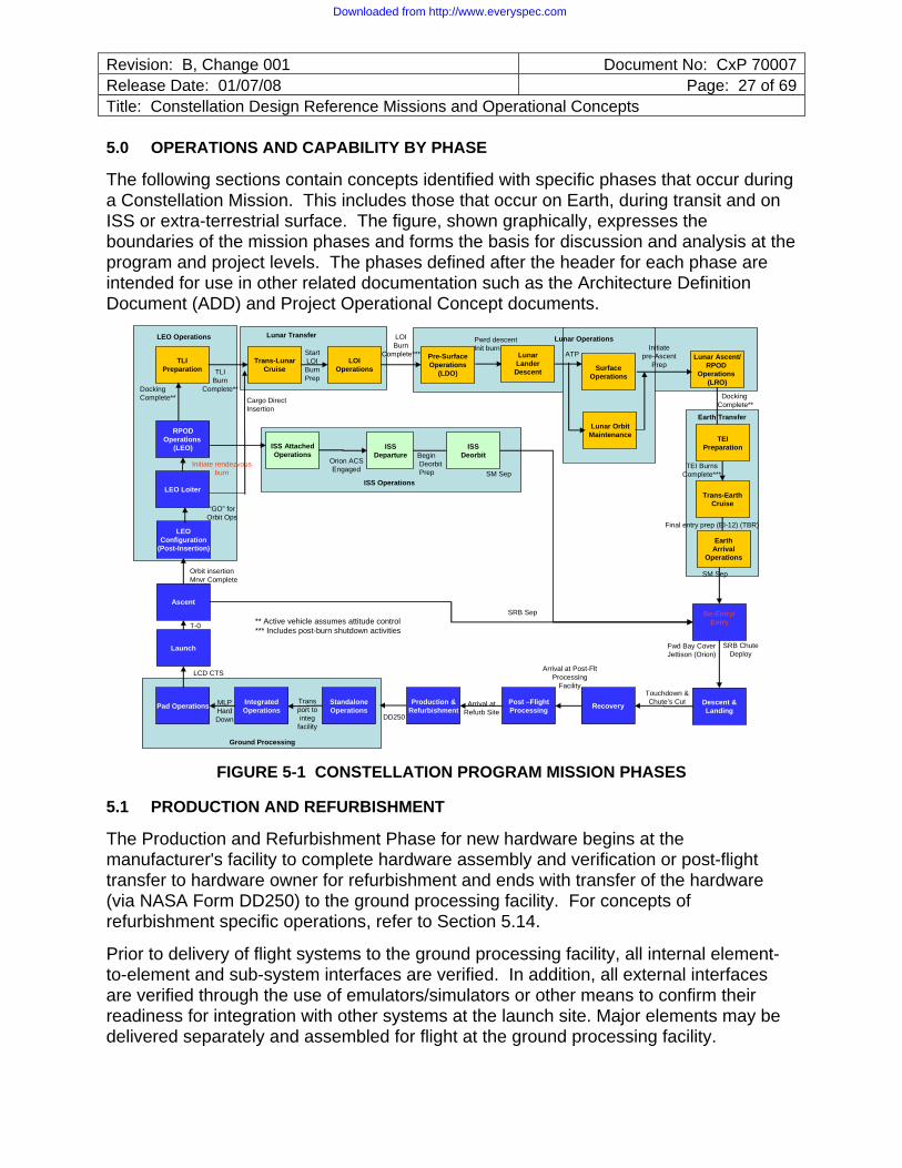
The following sections contain concepts identified with specific phases that occur during a Constellation Mission. This includes those that occur on Earth, during transit and on ISS or extra-terrestrial surface. The figure, shown graphically, expresses the boundaries of the mission phases and forms the basis for discussion and analysis at the program and project levels. The phases defined after the header for each phase are intended for use in other related documentation such as the Architecture Definition Document (ADD) and Project Operational Concept documents.
RPODOperations
(LEO)
LOIOperations
Pre-Surface Operations
(LDO)
Lunar OrbitMaintenance
Lunar Ascent/RPOD
Operations (LRO)
Trans-Earth Cruise
ISSDeparture
ISS AttachedOperations
LEOConfiguration
(Post-Insertion)
Ascent
Launch
Re-Entry/Entry
Descent &LandingPad Operations Integrated
OperationsProduction &
RefurbishmentPost –FlightProcessing Recovery
“GO” for Orbit Ops
DockingComplete**
Orion ACS Engaged
Initiatepre-Ascent
PrepATP
LOIBurn
Complete***
Fwd Bay CoverJettison (Orion)
Touchdown &Chute’s Cut
LCD CTS
Orbit insertionMnvr Complete
Arrival at Post-Flt Processing
Facility
DD250
Arrival atRefurb Site
MLPHard Down
T-0
LEO Loiter
Trans-LunarCruise
TLIPreparation TLI
BurnComplete**
StartLOIBurnPrep
DockingComplete**
TEIPreparation
TEI BurnsComplete***
SM Sep
SM Sep
** Active vehicle assumes attitude control*** Includes post-burn shutdown activities
Initiate rendezvous burn
StandaloneOperations
Surface Operations
Ground Processing
Transport to integ
facility
ISSDeorbit
ISS Operations
LEO Operations Lunar Operations
SRB ChuteDeploy
SRB Sep
Cargo Direct Insertion
BeginDeorbitPrep
Lunar Transfer
LunarLander Descent
Pwrd descentInit burn
Earth Transfer
Earth Arrival
Operations
Final entry prep (EI-12) (TBR)
FIGURE 5-1 CONSTELLATION PROGRAM MISSION PHASES
5.1 PRODUCTION AND REFURBISHMENT
The Production and Refurbishment Phase for new hardware begins at the manufacturer's facility to complete hardware assembly and verification or post-flight transfer to hardware owner for refurbishment and ends with transfer of the hardware (via NASA Form DD250) to the ground processing facility. For concepts of refurbishment specific operations, refer to Section 5.14.
Prior to delivery of flight systems to the ground processing facility, all internal element-to-element and sub-system interfaces are verified. In addition, all external interfaces are verified through the use of emulators/simulators or other means to confirm their readiness for integration with other systems at the launch site. Major elements may be delivered separately and assembled for flight at the ground processing facility.
Downloaded from http://www.everyspec.com
Revision: B, Change 001 Document No: CxP 70007Release Date: 01/07/08 Page: 28 of 69Title: Constellation Design Reference Missions and Operational Concepts
Anomalies are resolved prior to shipping to minimize deferred work and reduce flight system time at the launch site.
Any task that can be done at the contractor’s manufacturing, test and integration facility is completed to minimize work and schedule risk at the ground processing facility. This could include off-gassing tests, an over-pressurization leak check (“whistle test”) to verify valve configuration on all pressurized modules, Government Furnished Equipment (GFE) (e.g. parachutes, docking system) component processing and integration into the spacecraft elements and LRU installation. Weight measurements are performed.
Pre-ship and pre-delivery reviews, to include representation by the receiving site, are performed to establish the readiness of each of the Constellation Systems for transport.
Prior to delivery of the flight systems, GSE and processing facilities at the ground processing facility are verified and ready to support delivery and processing of the hardware.
The Constellation Systems are to be shipped to the launch site and delivered to the ground processing facility with appropriate environmental protection, controls, and monitoring.
During transportation, the systems need minimal services, such power or purge, to limit transportation costs.
5.2 GROUND PROCESSING
The Ground Processing Phase begins at hardware delivery to the ground processing facility and ends at commencement of the launch countdown.
The Ground Operations Project provides Ground Processing Services to the flight hardware from delivery through SRB ignition.
5.2.1 Standalone Operations
Standalone Operations Phase begins at DD250 and ends with commencement of transportation to integration facility.
5.2.1.1 Spacecraft
The spacecraft are transported to a designated processing facility that provides a clean work area for processing. Orion arrives for ground processing with the CM/SM/SA integrated. Purge is provided to Orion for temperature and humidity control. The Lander arrives for ground processing in separate elements.
GSE is connected, verified, and monitored. If necessary, the elements such as the Launch Abort System (LAS) are accepted in a separate processing facility. GSE attach points are easily accessible and ground handling systems take advantage of pre-existing structural attach points.
Downloaded from http://www.everyspec.com
Revision: B, Change 001 Document No: CxP 70007Release Date: 01/07/08 Page: 29 of 69Title: Constellation Design Reference Missions and Operational Concepts
Receiving inspections, shipping instrumentation data review, and post-delivery checkout are performed to verify no damage has occurred during transportation. The ground team establishes internal and external access to the spacecraft elements as necessary.
The spacecraft systems are delivered with no open work; however, in special cases, any government-approved deferred work from the manufacturing, integration, and test site is completed at the ground processing facility. Corrective action is implemented for any failed components. For example, in contingency cases, the fairing may be installed by at the ground processing facility. The necessary resources, flight hardware, and GSE, and schedule are in place to complete assembly of the spacecraft elements.
As the Lander spacecraft elements are integrated, the newly established interfaces are checked out incrementally.
For flights involving vehicle systems being flown for the first time in an integrated launch vehicle stack or that incorporate significant modifications from previously flown versions, ground processing provides for expanded verification testing to verify the interoperability between the integrated elements and systems (beyond that previously checked out through emulators/simulators).
The spacecraft is inspected and any final stand-alone assembly, integration, servicing, (including servicing of all propellants and high pressure gasses) testing and closeouts are completed in preparation for integration with the launch vehicle systems.
Crew tool and equipment fit checks, access verification and overall inspections of flight hardware are performed in or near flight configuration. Time-critical cargo is fit checked with the Orion or Lander. The crew or crew representative participates in these activities to ensure the highest level of readiness for flight.
Orion and Lander provide a system for integration, restraint, and translation of cargo items compatible with pre-launch, launch, ascent, micro-gravity, descent and post-landing environments. Pre-packed cargo are delivered to the processing facility and integrated into the vehicle. Changes to the configuration of delivered pre-packaged cargo, crew equipment and experiments are completed at the launch site prior to loading into the flight system while in the processing facility.
The Lander to EDS adapter and shroud are integrated in a ground processing facility prior to deliver at the vehicle integration facility.
Prior to final preparation for spacecraft transfer to the vehicle integration facility, closeouts are performed. The spacecraft is then configured for transport. The spacecraft is transported to the launch vehicle integration facility.
5.2.1.1.1 Orion/ISS Integrated Testing
The first time Orion is to be launched on an ISS mission, Orion is integrated with an ISS emulator/simulator in the standalone processing facility to verify interoperability and functionality between Orion and ISS systems. Subsequent integration testing between Orion and ISS emulator/simulator is performed only when significant ISS or Orion
Downloaded from http://www.everyspec.com
Revision: B, Change 001 Document No: CxP 70007Release Date: 01/07/08 Page: 30 of 69Title: Constellation Design Reference Missions and Operational Concepts
modifications are made that potentially impact Orion and ISS interfaces and/or integrated operability or functionality.
5.2.1.1.2 Orion/Lander Integrated Testing
Prior to launching an Orion to be integrated with a Lander in space for the first time, Orion and Lander are integrated together at the launch site to perform integrated testing to verify the interoperability and functionality of Orion and Lander systems. Subsequent integration testing between Orion and Lander at the launch site is performed only when significant Lander or Orion modifications are made that potentially impact Orion and Lander interfaces or their integrated operability.
5.2.1.2 Ares I Standalone Ground Processing
First Stage components are delivered from the manufacturer or refurbishment facility to a hazardous processing facility for sub-system processing, integration and testing. The First Stage components are then delivered to the vehicle integration facility, stacked, tested, and closed out for flight. Beginning with First Stage integration onto the mobile launcher, the Ares I/Orion is capable of being integrated, tested, serviced and launched within six weeks.
The Upper Stage arrives at the launch site as a complete stage with a J-2X engine and interstage installed, checked out in the integration facility, and ready to be stacked onto the First Stage within two days following arrival at the launch site.
The Upper Stage is then rotated and installed on the First Stage frustum. Powered testing of interfaces (within the integrated Ares I is not required although some verification of successful hardware integration, , may be performed. Interfaces between Ares I and the ground systems are established and verified. Ares I interfaces to the Mobile Launcher/Launch Umbilical Tower (LUT) are established and verified followed by checkout of the integrated Ares I. Throughout integration, repetitive testing is avoided.
5.2.1.3 Ares V Standalone Ground Processing
SRB components are delivered from the manufacturer or refurbishment facility to a hazardous processing facility for sub-system processing, integration, and testing. The SRB components are then delivered to the vehicle integration facility, stacked, tested, and closed out for flight. Beginning with SRB integration onto the Integrated Launcher, the Ares V/Lander is capable of being integrated, tested, serviced and launched within six weeks.
The Core Stage arrives at the launch site as a complete stage with five RS-68 engines installed, checked out in the vehicle integration facility and ready to be stacked onto the mobile launcher within two days following arrival at the launch site. The Core Stage is checked out, rotated, mated, and tested with the SRBs.
The EDS arrives at the launch site as a complete stage with a J-2X engine and interstage installed, checked out in the integration facility, and ready to be stacked onto the Core Stage within two days following arrival at the launch site.
Downloaded from http://www.everyspec.com
Revision: B, Change 001 Document No: CxP 70007Release Date: 01/07/08 Page: 31 of 69Title: Constellation Design Reference Missions and Operational Concepts
The EDS undergoes post-delivery checkout, is rotated, mated and tested with the Ares V first stage (Core Stage and SRBs). Interfaces (e.g. continuity) within the integrated Ares V, and with the ground systems are established and verified. Ares V interfaces to the Mobile Launcher/LUT are established and verified followed by checkout of the integrated Ares V vehicle.
5.2.2 Integration
The Integration Phase begins with stacking on the Mobile Launcher and ends at Pad hard down.
The ground processing flow includes end-to-end interface testing between the spacecraft, launch vehicles, processing facilities and external services. All flight interfaces including mechanical, fluid, electrical, gases, propellants, and data interfaces related to command and control, and communications are verified using either flight hardware or flight hardware emulators and flight software. This verifies end-to-end connectivity and functionality between the flight system, and mission control and launch facilities. The flight, ground and external systems each provide their side of the interface necessary to perform these tests.
5.2.2.1 Ares I/Orion Integrated Stack Processing
All Ares Orion stacking is performed on the mobile launcher. De-integration of the Ares I/Orion is not required to repair or replace failed components in either system for resolution of reasonable contingency scenarios.
Ground interfaces are established, verified, and monitored. Orion to Ares I continuity checks are performed.
The LAS is integrated with the Orion flight element in the launch vehicle integration facility to form the completed integrated stack. CM to LAS interfaces are verified prior to LAS installation. (Trade) Following integration, interfaces between Orion and Ares I are tested and verified.
Hazardous processing (e.g. ordnance installation, propellant servicing) and non-hazardous servicing (e.g. GN2 tank top off) is performed prior to transportation of the integrated vehicle to the launch Pad (during element standalone, system standalone,) to avoid addition of serial work to the integration facility or Pad flows and because of loss of physical access. However, due to processing facility or safety restrictions, some hazardous operations (e.g. hypergolic propellant pressurization) are performed at the Pad. Common ground system-to-flight vehicle interfaces are used for all hypergolic servicing to simplify loading.
An end-to-end and mission sequence test is completed to verify interfaces between flight systems, space-based systems, and Earth-based systems to establish readiness for all flight phases. Integrated launch training simulation and systems verification are performed in conjunction with end-to-end testing with the support of the suited crew as appropriate for the mission type. In support of integrated testing, personnel do not enter
Downloaded from http://www.everyspec.com
Revision: B, Change 001 Document No: CxP 70007Release Date: 01/07/08 Page: 32 of 69Title: Constellation Design Reference Missions and Operational Concepts
the non-habitable volume of the vehicle to decrease the risk of personnel injury and hardware damage. This reduces processing time and limits specialized access platforms.
Once end-to-end integrated testing is completed, all final closeouts (except for the crew habitable volume) are performed. The integrated stack is then ready for transport to the pad. Purge services will be supplied to the integrated launch vehicle/mobile launcher as it is transported to the pad.
5.2.2.2 Ares V/Lander Integrated Stack Processing
All stage interfaces (power and communication) within the integrated vehicle, and with the ground systems are established, tested and verified. External interfaces to the Lander are tested and verified.
Following integration, interfaces between the Lander, Lander spacecraft adapter, and Ares V are tested and verified.
The Lander is integrated with the Ares V. De-integration of the Ares V/Lander is not required to repair or replace failed components in either system for resolution of reasonable contingency scenarios.
Hazardous processing (e.g. ordnance installation, propellant servicing, O2 tank top off) and non-hazardous servicing are performed prior to transportation of the integrated vehicle to the launch Pad (during element standalone, system standalone, and vehicle integrated processing) to avoid addition of serial work to the Pad flow and because of the loss of physical access. However, due to processing facility or safety restrictions, some hazardous operations (e.g. hypergolic propellant pressurization) are performed at the pad. Common ground system-to-flight vehicle interfaces are used for all hypergolic and cryogenic servicing to simplify loading. To the greatest extent possible the hypergolic fluids are common among all Constellation elements.
Access to Ares V is established in the integration facility. An end-to-end integrated mission sequence test is completed to verify interfaces between flight systems, space-based systems, and Earth-based systems to establish readiness for all flight phases. Integrated launch training simulation and systems verification are performed in conjunction with end-to-end testing. Personnel do not enter the non-habitable volume of the vehicle to decrease the risk of personnel injury and hardware damage. This reduces processing time and limits specialized access platforms.
Once integrated testing is complete, closeouts are performed. The integrated stack is then ready for transport to the pad.
5.2.3 Pad Operations
Pad Operations Phase starts at Pad hard down and ends with commencement of Launch Countdown.
Downloaded from http://www.everyspec.com

Revision: B, Change 001 Document No: CxP 70007Release Date: 01/07/08 Page: 33 of 69Title: Constellation Design Reference Missions and Operational Concepts
Operations to be performed at the pad will be limited to those necessary, with a goal of reducing pad stay time to an absolute minimum. The integrated stack will be readied for the planned launch attempt within seven days of arrival at the Pad.
At the launch pad, limited access is established, including crew cabin access for Ares I/Orion. Integrated launcher to launch pad interfaces are established. Vehicle and ground systems interfaces which could not previously be verified are tested.
Hazardous and non-hazardous commodity servicing is completed. The tanking decision is made simultaneously for both Ares I and Ares V vehicles.
5.3 LAUNCH
The Launch Phase begins at commencement of the Launch Countdown and continues through ignition of the launch vehicle booster(s). Ground Operations conducts launch countdown through liftoff.
For lunar missions, the Ares I/Orion nominally launches within 90 minutes after the Ares V/Lander has been successfully launched. Launch opportunities occur for seven consecutive days (four attempts for both vehicles followed by three more attempts for the Ares I/Orion) before the injection opportunity to depart LEO for the Moon has closed. This ensures successful launch and on-orbit checkout of EDS and Lander prior to committing the crew to launch. However, it is possible to maintain the EDS/Lander in a loiter orbit until Orion arrives (Trade). Timely launches of both the cargo and crew achieve a balance of crew and cargo exposure to the space environment, consumable and propellant depletion, launch flexibility due to unforeseen problems, and injection opportunities to the Moon.
The Eastern range assigns a maximum time block for supporting a launch attempt of typically several hours to fully envelope the launch window for a given day. The ground system elements accommodate a window of approximately two hours regardless of the actual launch window. The actual launch window may be reduced within the launch period based on: flight mechanics, ascent performance, yaw steering capability, target vehicle orbit, over flight considerations, and Solid Rocket Motor (SRM)/upper stage recovery/disposal constraints. The Ares V cargo insertion and Ares I launch are designed to provide a 90-minute planar launch window (Trade) for Orion with a launch day rendezvous opportunity.
Launch holds are sufficiently adaptable to respond to non-emergency contingencies. The launch team has the capability to hold and resume the countdown at predetermined points in the launch sequence. Depending on the timing and reason for the hold, as well as the ability to achieve system readiness and meet the launch criteria and launch window, the countdown may resume and proceed through liftoff, or a scrub may be called and the countdown recycled for a subsequent attempt.
Downloaded from http://www.everyspec.com
Revision: B, Change 001 Document No: CxP 70007Release Date: 01/07/08 Page: 34 of 69Title: Constellation Design Reference Missions and Operational Concepts
5.3.1 Ares V/Lander
Propellants and cryogenics loading, replenishing and/or pressurization activities are completed. Final ordnance operations and vehicle closeouts are performed. Final configuration, checkout and inspection of launch vehicle, spacecraft and facility systems are performed remotely (from the Launch Control Center [LCC]) to minimize the need for pad access.
Ground-computed updates to ascent guidance parameters such as Day of Launch I-Loads and rendezvous planar targets are uplinked to the integrated vehicle, if required.
Ground Operations, Mission Operations, Engineering and onboard vehicle systems monitor the progress of the countdown and verify the integrity of command links between flight systems, space-based systems, and Earth-based systems. Health and Status is monitored and communicated to provide insight into anomalies that might initiate a launch hold, scrub turnaround, or ground crew emergency egress.
Launch Control, Mission Control, and all systems are placed in final flight configuration and verify that their own ground systems are ready to support the mission. Periodic weather evaluations track launch conditions through launch commit.
Constellation Mission Management makes a go/no-go launch decision based on their evaluation of compliance with all Launch Commit Criteria (LCC), flight rules, and range safety rules.
Prior to launch commit, remaining final configuration and automated verification of systems are completed and the integrated stack is ready for launch.
Nominal terminal countdown results in launch of the vehicle at T-0 when booster stage and Core Stage ignition occurs and the integrated stack lifts off from the launch pad. All interfaces between the launch vehicle and the ground, such as mechanical, fluid, and data interfaces, disconnects and umbilicals are separated from the integrated stack prior to lift-off. Prior to Core Stage and SRB ignition, Ground Operations monitors and controls the integrated stack systems operations. Transfer of the ability to terminate the launch from Ground Systems to onboard systems occurs shortly before SRB ignition. However, ground override capability of the launch is retained up until SRB ignition to allow Range the capability to prevent the launch if necessary.
Ground system safing and turnaround operations commence to prepare the systems for the next launch.
5.3.2 Ares I/Orion
Final stowage of time-critical cargo is completed. Power is provided to the cargo, as required. Batteries are charged and verified ready for flight. Orion allows simple cargo installation (and removal for launch delays) for cargo installed at the pad.
Downloaded from http://www.everyspec.com

Revision: B, Change 001 Document No: CxP 70007Release Date: 01/07/08 Page: 35 of 69Title: Constellation Design Reference Missions and Operational Concepts
Propellants and cryogenics loading, replenishing and/or pressurization activities are completed. Final ordnance operations and vehicle closeouts are performed. Final configuration, checkout and inspection of launch vehicle, spacecraft and facility systems are performed remotely (from the Launch Control Center [LCC]) to minimize the need for pad access.
The fully suited crew ingresses, all crew-to-spacecraft interfaces (e.g., life support and communications) are connected and tested, and the crew is secured in the vehicle. This includes a suit leak check. A ground operations close-out team assists the crew with ingress though the crew is capable of securing themselves if required.
Post-ingress, automatic system configuration and automatic switch position verification are completed. The hatch is closed and secured by ground personnel. A hatch seal leak check as well as a habitable volume gross leak check is performed on the crew module per launch attempt to verify hatch seal integrity and pressurized volume integrity. The closeout team enables the LAS, then clears the pad. Orion's hatch is capable of being closed/latched and unlatched/opened, from either inside or outside in a timeframe appropriate to support closeout, recovery, and emergency egress timelines.
Ground-computed updates to ascent guidance parameters such as Day of Launch I-Loads and rendezvous planar targets are uplinked to the integrated vehicle, if required.
Ground Operations, Mission Operations, Engineering and onboard vehicle systems monitor the progress of the countdown, perform voice communications checks with the crew, and verify the integrity of data and command links between flight systems, space-based systems, and Earth-based systems. Health and Status is monitored and communicated to provide insight into anomalies that might initiate a launch hold, scrub turnaround, emergency egress, or abort.
Launch Control, Mission Control, and all systems are placed in final flight configuration and verify that their own ground systems are ready to support the mission.
During terminal count, the Ares I and Orion perform limited operation and final checkout of their respective systems, in preparation for flight. Periodic weather and sea state evaluations are performed to provide status to the launch team.
Constellation Mission management makes a go/no-go launch decision based on their evaluation of compliance with all Launch Commit Criteria (LCC), flight rules, and range safety rules. For ISS missions, readiness is additionally ascertained from ISS Mission Management.
Prior to launch commit, remaining final configuration and automated verification of systems is completed and the integrated stack is ready for launch. Crew visors are down and gloves are on. Transfer of the ability to terminate the launch from Ground Systems to onboard systems occurs shortly before SRB ignition. Ground Systems to onboard systems occurs shortly before SRB ignition. However, ground override capability of the launch is retained up until SRB ignition to allow Range the capability to prevent the launch if necessary.
Downloaded from http://www.everyspec.com
Revision: B, Change 001 Document No: CxP 70007Release Date: 01/07/08 Page: 36 of 69Title: Constellation Design Reference Missions and Operational Concepts
Nominal terminal countdown results in launch of the vehicle at T-0 when first stage ignition occurs and the integrated stack lifts off from the launch pad. All interfaces between the launch vehicle and the ground, such as mechanical, fluid, and data interfaces, disconnects and umbilicals are separated from the integrated stack prior to or during lift-off.
Ground system safing and turnaround operations commence to prepare the systems for the next launch.
5.4 ASCENT
The Earth Ascent Phase begins at ignition of the launch booster(s) and continues through the orbit insertion maneuver that places the cargo into a stable low earth orbit.
Orbit insertion can be achieved by the launch vehicle or a combination of the launch vehicle and spacecraft. Mission Operations conducts ascent and mission operations through Earth landing with support as required from System-provided engineering.
5.4.1 Ares V/Lander
At SRB ignition this responsibility transfers to Mission Operations.
Ares V monitors vehicle health and status and controls the integrated vehicle trajectory. Mission Systems monitors vehicle system using space-based telemetry streams. Both Mission Systems and United States Air Force (USAF) Range Safety personnel monitor trajectory performance using space-based telemetry and independently evaluating ground-based tracking data.
The Core Stage inserts the Lander/EDS to the Ascent Target (Lunar). Following Core Stage thrust termination, EDS/Lander separation from Ares V is initiated. The Ascent Target conditions provide for safe Core Stage reentry. (See Entry.)
Following separation from the Core Stage, the EDS is ignited and completes the insertion into Earth Rendezvous Orbit (ERO).
5.4.2 Ares I/Orion
Unpressurized cargo remains in its launch configuration and does not interfere with Orion operations during Earth ascent and orbital insertion operations. Keep alive power services are provided to the unpressurized cargo during the ascent phase on a case by case basis.
At SRB ignition this responsibility transfers to Mission Operations.
Ares I and Orion monitor vehicle health and status. Ares I controls the integrated vehicle trajectory. Mission Systems monitors vehicle systems using space-based telemetry streams. Both Mission Systems and USAF Range Safety personnel monitor trajectory performance using space-based telemetry and independently evaluating ground-based tracking data.
Downloaded from http://www.everyspec.com
Revision: B, Change 001 Document No: CxP 70007Release Date: 01/07/08 Page: 37 of 69Title: Constellation Design Reference Missions and Operational Concepts
High speed and high resolution still and motion imagery is captured of configuration, condition, performance, and environment of the launch vehicle from liftoff through Orion separation from upper stage, including, in cabin imagery, ground systems, and vehicle based acquisition. Post-launch imagery is transmitted to the ground in real-time or near real-time.
Ares I GN&C is prime during nominal ascent with Orion in a passive monitoring mode. The crew has the ability to manually control the system within vehicle margins.
When the Ares I first stage chamber pressure drops below a predetermined value, it separates from the Ares I upper stage, and upper stage ignition occurs. The nominal ascent trajectory is designed to ensure safe separation, reentry and landing of the first stage in the ocean. (See Entry.)
Orion automatically commands Launch Abort System jettison when its use is no longer required for an ascent abort. The LAS safely reenters and is disposed of in the ocean.
The Ares I upper stage inserts Orion to the Ascent Target.
After Ares I upper stage cut-off, Orion issues the Orion to upper stage separation command. After separation from Orion, the Ares I upper stage follows the designed trajectory to avoid collision and Orion performs programmed avoidance maneuvers, if required, to ensure safe separation and disposal of the Ares I upper stage.
Orion completes insertion into a stable Low Earth Orbit (LEO). Orion performs orbital phasing maneuvers to achieve a relative trajectory profile to complete rendezvous and docking operations. For crewed lunar missions, the orbit where near-field Orion rendezvous and docking activities with the Lander/EDS occur is identified as Earth Rendezvous Orbit (ERO). Mission Operations confirms the Orion orbit insertion burn solution.
5.5 LOW EARTH ORBIT (LEO) OPERATIONS
The LEO Operations Phase begins at completion of the orbit insertion maneuver (the first rendezvous maneuver) and ends at the completion of the TLI burn.
5.5.1 LEO Configuration (Post Insertion)
The LEO Configuration Phase begins at completion of orbit insertion maneuver and ends at the “Go for orbit operations” for Orion, EDS and Lander.
Upon reaching a stable LEO, Orion automatically deploys any antennas, solar arrays, and other appendages per a pre-planned sequence.
The on-orbit verification of Orion systems health is performed within approximately the first orbit.
Post-insertion reconfiguration activities are minimal, ideally limited for stowage and minor cabin reconfiguration for orbit operations, including Orion cabin pressure
Downloaded from http://www.everyspec.com
Revision: B, Change 001 Document No: CxP 70007Release Date: 01/07/08 Page: 38 of 69Title: Constellation Design Reference Missions and Operational Concepts
transition for lunar missions, and to allow Flight Day 1 rendezvous. The crew remains suited with gloves donned, but visors may be up for the docking operation.
Services (power and data) are provided to unpressurized cargo and activation may occur after the Orion is configured for on-orbit operations.
5.5.2 LEO Loiter
The LEO Loiter Phase begins at "Go for orbit operations" and ends with the initial rendezvous burn. For single launch cargo missions, the LEO Loiter Phase ends at completion of the TLI burn. EDS GN&C is prime during on-orbit operations prior to docking with Orion. Since the Lander is powered to a quiescent state, EDS provides navigation, mode, health, trajectory data, etc. to Mission Operations. Mission Operations computes EDS/Lander trajectory updates and performs an on-orbit verification of systems health.
5.5.3 Rendezvous, Proximity Operations and Docking (RPOD) Operations (LEO)
The Rendezvous, Proximity Operations and Docking (RPOD) Operations Phase (LEO) begins at the start of the initial rendezvous burn and ends when docking is complete and EDS or ISS assumes attitude control.
Orion performs orbit shaping burns to rendezvous with the target. Rendezvous can take up to two days or could be accomplished on the same day as launch depending on mission plans and target phase angle.
The Orion spacecraft performs the rendezvous and mating as the active element and without requiring the passive elements to fly outside their normal operational envelope.
The crew can fly Orion manually using direct visual cues during rendezvous, proximity operations and mate with the target vehicle. The crew can intercede in automated rendezvous sequences at any point and can engage automation as desired.
To provide flexibility in mission design and real-time operations, Orion is not constrained to specific on-orbit lighting conditions or ground pass requirements for rendezvous operations.
The Orion crew or ground control has the option to command a maneuver hold or break-off the attempt to mate with another element at any time during the proximity operation.
Orion protects for at least one re-rendezvous attempt during this phase, with a maximum 24-hour gap between the two attempts.
For ISS rendezvous and docking, the Orion crew and the ISS crew directly communicate with each other during rendezvous (not relayed via the ground). The Orion and ISS crews monitor the approach of Orion with tools that are sufficient to ensure the approach is safe. Either crew has the ability to abort/hold the approach and
Downloaded from http://www.everyspec.com
Revision: B, Change 001 Document No: CxP 70007Release Date: 01/07/08 Page: 39 of 69Title: Constellation Design Reference Missions and Operational Concepts
docking. The Orion crew has the capability to dock with the ISS should the ISS be temporarily vacated.
5.5.4 The Trans-Lunar Injection (TLI) Preparations Phase
The Trans-Lunar Injection (TLI) Preparations Phase begins when Orion-to-EDS/Lander docking is complete and EDS assumes attitude control, and ends at completion of the TLI burn.
5.6 ISS OPERATIONS
The ISS Operations Phase begins when docking with ISS is complete and continues through SM separation.
5.6.1 ISS Attached Operations
The ISS Operations Phase begins when docking with ISS is complete and ends when the Orion Attitude Control System (ACS) is engaged for departure.
The Orion-to-ISS umbilicals are mated during the automatic docking sequence when structural interfaces are being rigidized. Following docking, the Orion or ISS crew (both are capable) pressurizes the vestibule between the two docked vehicles and performs a leak check. The hatches are opened and Orion is configured to quiescent mode. The cargo transfer operations are performed by crew throughout attached operations.
Orion remains docked for up to a 180-day increment (maximum of 210 days with contingency) including crew handover and in standard ISS attitudes.
The hatch between ISS and Orion remains open with a common environment maintained by ISS atmospheric control systems. While attached to the ISS, Orion is in the quiescent (low power) mode while maintaining air circulation and a minimum of safety monitoring and isolation functions, such as fire detection and air flow termination. During attached operations, in case of an ISS contingency, Orion assumes a safe haven and return vehicle role for the duration of the ISS increment. Telemetry from Orion is sent to Mission Systems to be used for Orion system monitoring via the ISS Program assets. ISS Program assets are used to uplink and route Mission Systems commands to Orion.
Orion operates in a stable configuration with limited real-time ground support during specific contiguous periods of active monitoring, command and control. As operations mature, Orion operates without ground or crew command and control. Orion queries and reconfigurations are sent from Mission Operations to Orion via the ISS.
The crew transfers the Orion cargo via the pressurized vestibule. The Orion-provided stowage system maximizes efficiency of crew transfer operations.
It may be necessary to demate Orion from ISS and relocate the vehicle to another port to accommodate ISS or Orion operational constraints or perform special tasks.
Downloaded from http://www.everyspec.com
Revision: B, Change 001 Document No: CxP 70007Release Date: 01/07/08 Page: 40 of 69Title: Constellation Design Reference Missions and Operational Concepts
While Orion is still docked to the ISS, nominal deorbit planning will allow for up to seven days to gain access to an acceptable landing opportunity to the predetermined ISS-return primary landing site. Secondary landing sites are considered backup sites and used only when insufficient opportunities to the primary landing site are determined. Once a landing opportunity is determined acceptable to target either the primary landing site or target a secondary landing site, then the Orion proceeds to the ISS Departure Phase.
Preparing for departure, the Orion crew dons their suits and returns to the spacecraft and Orion and ISS hatches are closed. The Orion crew depressurizes the interface and performs a leak check with Mission Systems support. The computation of de-orbit opportunities, de-orbit maneuvers, and Earth entry trajectories can be performed on-board Orion and/or by Mission Operations. However, the on-board crew has sufficient capability to return without subsequent communication with the ground. The ability to uplink an alternate entry plan is provided when communications links are available.
The crew remains suited but visors may be up for undocking. The ACS is disengaged and Orion undocks. (See Section 5.10, Re-Entry/Entry.)
5.6.2 ISS Departure
The ISS Departure Phase begins when the Orion ACS is engaged and ends when deorbit preparation is started.
5.6.3 ISS Deorbit
The Deorbit Phase begins at initiation of deorbit preparations and ends at SM separation. SM performs the deorbit burn. The SM, then the Low Impact Docking System (LIDS), is jettisoned and the CM proceeds toward nominal entry
5.7 LUNAR TRANSFER
The Lunar Transfer begins at the completion of TLI burn and ends when the LOI burn is complete.
Once Orion has mated with the Lander, and communication connections are automatically established through the mating mechanism. Orion provides air exchange to the Lander. Orion verifies the docking interface and equalizes pressure between the two vehicles. Opening the hatch between Orion/Lander can be accommodated by both vehicles for up to 90 minutes for two crew ingress to the Lander.
The Lander is powered up and its systems checked out. The Lander (Trade-thru Orion) provides system health check data to Mission Systems.
The crew may enter the Lander prior to TLI, but are located in Orion for TLI. Suits are donned for the TLI burn. Hatches may be closed during the TLI burn.
Mission Operations updates TLI targets and maneuver data, if required.
Downloaded from http://www.everyspec.com
Revision: B, Change 001 Document No: CxP 70007Release Date: 01/07/08 Page: 41 of 69Title: Constellation Design Reference Missions and Operational Concepts
The EDS propulsion, attitude control and GN&C systems are used to execute the TLI maneuver of the EDS/Lander/Orion stack. The Orion, Lander and Mission Operations independently monitor the maneuver execution.
5.7.1 Trans-Lunar Cruise (TLC)
The Trans-Lunar Cruise (TLC) Phase begins when the TLI burn is complete and Lander assumes attitude control, and ends at the start of the LOI burn preparation.
Orion commands Lander to execute the Orion/Lander separation from the EDS (Trade). Hatches may be reopened post EDS jettison. After a positive separation event, the EDS maintains attitude control of itself in preparation for subsequent programmed disposal maneuvers.
Pressurized suits worn for the Trans-Lunar Injection (TLI) burn are doffed for Trans-Lunar Cruise (TLC).
During TLC, the Lander performs navigation, guidance and attitude control for the Orion/Lander stack. During these maneuvers, Orion monitors these commands and updates its position and navigation information. Mission Operations monitors the trajectory and confirms maneuver computations.
Power may be transferred between Orion and Lander to provide additional margin for future flight phases.
The Lander performs mid-course correction burns during TLC (Trade), and the Lunar Orbit Insertion (LOI) burns that establish the lunar reference orbit required for descent to the landing site. During the TLC phase, navigation is performed initially by ground processing the radiometrics on the communications link with the Deep Space Network (DSN). Ground-based navigation for the end of the cruise phase and LOI utilize lunar vicinity assets including the lunar communication relay satellites; however, the DSN is still available as needed. Mission Systems computes the final maneuver parameters and uplinks the results to the crew. Although the maneuvers are nominally executed automatically, the crew may manually execute maneuvers from their crew stations, if required.
Orion and Lander share health and status data, as well as independently report their health and status to Mission Operations. If off-nominal conditions are detected, both the crew and Mission Operations are notified for corrective action.
5.7.2 Lunar Orbit Insertion (LOI) Operations
The LOI Phase begins when the LOI burn preparations have begun and ends when the LOI burn is complete.
Pressurized suits may be donned and hatches may be closed prior to the LOI burn. Suits may be doffed and hatched may be reopened post LOI burn.
Downloaded from http://www.everyspec.com
Revision: B, Change 001 Document No: CxP 70007Release Date: 01/07/08 Page: 42 of 69Title: Constellation Design Reference Missions and Operational Concepts
EDS GN&C is prime during on-orbit operations post-EDS/ Lander/Orion docking until EDS separation from Orion/ Lander. Orion and EDS provide navigation, mode, health, trajectory data, etc. to Mission Operations. Mission Operations computes trajectory updates and performs an on-orbit verification of systems health.
5.8 LUNAR OPERATIONS
The Lunar Operations Phase begins at completion of the LOI burn and ends at Lander-to-Orion docking complete when Orion assumes attitude control.
5.8.1 Pre-Surface Operations (Lunar Destination Orbit)
The Pre-Surface Operations Phase begins at completion of the LOI burn and ends at the completion of the initial burn for Lunar descent.
Once in lunar orbit, the Orion/Lander augments Mission Operations state vector updates with onboard navigation using any available lunar assets such as orbiting navigation satellites, surface beacons, celestial observations, and surface feature tracking. Lunar orbits include the full range of inclinations to provide for global lunar access. Adequate onboard navigation supports autonomous return capability, and as vehicle operations experience is gained, the onboard capability may mature into a primary system.
All equipment and consumables required for surface operations are located in the Lander to allow independent operation following separation from Orion.
Lander systems are checked out and autonomous Orion systems are fully demonstrated.
Suits are donned with visors up for Lander separation and visors down for powered descent initiation and lunar landing. For the initial mission, all but one member (Trade) of the crew transfers to Lander. For follow-on missions, the entire crew transfers to the Lander. Hatches are closed and the Lander undocks from Orion and descends to the lunar surface. Descent and hazard avoidance are automated (Trade). Mission Operations monitors all descent operations.
The Orion/Lander may loiter in Lunar Destination Orbit (LDO) in order to provide proper orbit phasing to reach certain landing sites. Once ready to descend to the surface, the Lander undocks from Orion then performs the required burns to transfer from LDO to an intermediate transfer orbit.
5.8.2 Lunar Lander Descent
The Lunar Lander Descent Phase begins with the completion of the initial burn for Lunar descent and ends with “Authority to Proceed” (ATP) with Lunar surface operations.
After cruising to near perilune, the Lander begins a powered descent profile to the designated landing site. During powered descent, the crew assesses and may
Downloaded from http://www.everyspec.com
Revision: B, Change 001 Document No: CxP 70007Release Date: 01/07/08 Page: 43 of 69Title: Constellation Design Reference Missions and Operational Concepts
redesignate the landing site, as required. Lunar Sortie missions are conducted during lunar surface daylight.
5.8.3 Surface Operations
The Surface Operations Phase begins with "Authority to Proceed" (ATP) with Lunar surface operations and ends with the initiation of ascent preparations. This Phase occurs in parallel with the Lunar Orbit Maintenance Phase.
One of the first major operational decisions following a lunar landing is the “stay/no-stay” decision. The crew and Mission Operations evaluate Lander systems status and Lander stability and orientation at the landing site with respect to the flight rules, and decide whether to proceed with the surface mission or immediately return to lunar orbit. A “no-stay” decision is followed by ascent to orbit and rendezvous with Orion.
Landing sites at the Lunar poles, farside, or other regions without line-of-sight communications with Earth use lunar relay satellites to support communications between the landing site and the Earth.
The emphasis of the surface activities is on EVAs, where sets of two or all four crew members don pressure suits and simultaneously conduct operations on the lunar surface outside of their landed spacecraft. Suits are doffed between EVAs while the surface crew is in the Lander.
For short duration missions, lunar post-landing and pre-ascent timelines are established which maximize EVA time available for exploration activities with appropriate consideration for crew health and safety.
Surface mobility systems allow all crew members to efficiently explore the local area given the requirements of the particular mission. Specific surface activities drive the nature of EVAs and mobility requirements.
A Lander airlock supports surface EVA activities and houses systems required for dust mitigation.
While inside their habitat (Lander or LSS habitat), the crew performs all routine aspects of eating, sleeping, housekeeping, exercise, and personal hygiene. IVA includes preparing and maintaining pressure suits, planning for subsequent operations on the lunar surface, and all activities associated with post-landing and pre-ascent operations.
In preparation for departure, suits are donned for Lander ascent with Orion with visors down and gloves on. Lander is powered up and its systems configured for ascent from the lunar surface. Final preparations are completed for ascent and rendezvous.
5.8.4 Lunar Orbit Maintenance
The Lunar Orbit Maintenance Phase begins with "Authority to Proceed" (ATP) with Lunar surface operations and ends with the initiation of ascent preparations.
Downloaded from http://www.everyspec.com
Revision: B, Change 001 Document No: CxP 70007Release Date: 01/07/08 Page: 44 of 69Title: Constellation Design Reference Missions and Operational Concepts
After the Lander successfully lands, and when left uncrewed, Orion is placed into a quiescent mode in which the minimum equipment remains running to perform needed standby functions and preserve onboard resources. Systems that remain active permit Mission Operations flight controllers to evaluate health and status and periodically perform maintenance as required. Orion maintains this mode, uncrewed, for up to seven days for Lunar Sortie Missions and up to 210 days for Lunar Outpost missions with periods of active monitoring contained in a limited daily period and active command and control restricted to specific contiguous periods with limited ground personnel involvement. (Note: For the shorter duration Lunar Sortie missions, Orion may not be put into a quiescent mode)
The possibility exists that Orion may be located to a higher orbit during destination operations (Trade). During this phase, Orion systems are monitored by both an Orion on-board autonomous integrated health management system and Mission Operations. The crew on the Lunar surface monitors Orion health and status via the Lander. Orion systems rely on redundancy and reconfiguration directed either by automatic onboard systems, the Lander crew or Mission Operations.
The quiescent mode maintains enough power and readiness in Orion systems to meet the requirements for quickly reactivating the vehicle in the event of a contingency departure from the surface. Orion systems are periodically reactivated by Mission Operations to conduct orbit adjustment maneuvers based on Mission Control Center (MCC)-computed targets.
After the surface stay is complete, Orion is reactivated by Lander and/or Mission Operations and is verified ready to support docking with the Lander ascent vehicle prior to surface departure. Mission Operations commands Orion to perform necessary orbital adjustments and plane changes for in-plane ascent and rendezvous of the Lander ascent vehicle.
5.8.5 Lunar Ascent/RPOD Operations (Lunar Rendezvous Orbit)
The Lunar Ascent/RPOD Operations Lunar Rendezvous Orbit (LRO) Phase begins with the initiation of ascent preparations and ends when Lander-to-Orion docking is complete and Orion assumes attitude control.
The Lander ascent vehicle performs in-plane ascent, rendezvous and mating with Orion in LRO with the Lander acting as the active spacecraft.
Once the crew leaves the surface, any systems left by the crew and continuing to operate support exploration activities via tele-operation by Mission Operations.
Lunar ascent from the landing site begins with a vertical rise and follows a minimum propellant profile inserting into a 9.8 x 54 nmi (18x100 km) transfer orbit.
After the powered ascent phase, the Lander cruises to apolune where it continues orbital adjustments in order to chase down and rendezvous with Orion, which has
Downloaded from http://www.everyspec.com
Revision: B, Change 001 Document No: CxP 70007Release Date: 01/07/08 Page: 45 of 69Title: Constellation Design Reference Missions and Operational Concepts
remained ahead of but within the line-of-sight of the Lander throughout the ascent phase. For docking with Orion, visors may be up.
After the hatches are open, the possibility exists that lunar dust enters the cabin Orion from Lander as equipment and crew are transferred.
5.9 EARTH TRANSFER
The Earth Transfer Phase begins at completion of Lander-to-Orion docking with Orion in attitude control, and ends after SM separation.
5.9.1 Trans-Earth Injection (TEI) Operations
The TEI Phase begins at completion of Lander-to-Orion docking with Orion in attitude control and ends when the TEI burns are complete.
After docking, the interface between Orion and the Lander ascent vehicle is pressurized and leak checked. The docking hatches are opened and the crew doffs and stows their suits. Returning cargo is transferred by the crew to Orion, along with any residual resources remaining on the ascent stage needed for Trans-Earth Cruise phase. The crew dons their suits but visors may be up for undocking. Orion undocks from the Lander ascent vehicle prior to Trans-Earth Injection (TEI) leaving the Orion portion of the docking system behind the Lander. The Lander Ascent Vehicle executes a controlled disposal on the lunar surface. Following jettison, the crew doffs their suits.
When returning to Earth, Mission Operations selects the landing location based on weather forecasts and other factors. The crew has sufficient information to select a landing location if they are unable to communicate with the ground.
The TEI burn uses the Orion service module propulsion system. Orion performs Guidance, Navigation, and Control (GN&C) functions for TEI execution, attitude control, and execution of mid-course maneuvers during Trans-Earth Cruise (TEC). Maneuver solutions may be MCC targeted or computed onboard.
For sites of favorable earth-return geometry, Orion performs a TEI burn that results in a direct Earth return trajectory. For higher inclination landing sites, Orion performs a burn to raise its parking orbit to a 24-hour intermediate lunar orbit, performs up to a 90° plane (node) change, and then cruises near perilune to complete TEI. For any departure condition, the TEI maneuver contains sufficient velocity change to affect full coazimuth control.
5.9.2 Trans-Earth Cruise (TEC)
The Trans-Earth Cruise Phase begins at completion of TEI burn and ends with start of final entry preparations (approximately E-12 hours).
The nominal TEC from the final TEI impulses to arrival at Earth vacuum perigee takes 96 hours (but could vary between 84 and 108 hours). This 24-hour variation in transit
Downloaded from http://www.everyspec.com
Revision: B, Change 001 Document No: CxP 70007Release Date: 01/07/08 Page: 46 of 69Title: Constellation Design Reference Missions and Operational Concepts
time allows the Earth to rotate in the inertial frame to change the longitude of the Earth touchdown point.
During TEC, Mission Operations is prime for navigation and maneuver targeting. During early TEC, ground processed navigation is performed using lunar vicinity in-situ resources and using Earth-based radiometric data. Prior to entry, navigation is augmented with utilization of radiometric data and Global Positioning System (GPS). Orion is prime for maneuver execution and attitude control. Mission Operations monitors trajectory and confirm maneuver computations.
During the Trans-Earth Cruise phase, the Orion navigation state is monitored, trajectory correction maneuvers are applied as necessary, and vehicle systems are checked out in preparation for atmospheric entry at Earth.
5.9.3 Earth Arrival Operations
The Earth Arrival Operations Phases begins when final entry preparations (approximately E-12 hours) begin and ends at SM separation.
The Orion habitable volume is reconfigured to the entry/landing configuration.
The entire crew dons suits in preparation for entry with gloves on. Prior to entry interface the crew visors are down.
As necessary, Orion or Mission Systems provides updates to onboard guidance for entry targets and trajectory correction maneuvers. The Orion CM separates from the SM and completes any necessary separation burn(s) and maneuvers to entry attitude.
5.10 RE-ENTRY/ENTRY OPERATIONS
The Entry Phase for Orion begins at SM separation and ends after the Orion Forward Bay Cover jettison.
The staging target conditions provide for safe Core Stage, Ares V SRBs, First Stage SRB, Upper Stage, LAS, LIDS, and SM impact with debris footprints in the targeted area of the ocean.
5.10.1 Crew Module (CM) Entry
After initial separation from the SM, the CM completes any necessary maneuvers to entry attitude.
The Orion SM is disposed ballistically in accordance with an approved debris footprint.
The Orion CM is capable of direct or skip entry return to Earth at Lunar return velocities, with future capability for skip entry return at Mars return velocities.
Orion jettisons the LIDS and forward bay cover in preparation for drogue chute deploy.
Automated deployment of the Orion CM drogue and chutes occurs at predetermined targets with activation of the landing attenuation system, if required, to reduce impact
Downloaded from http://www.everyspec.com
Revision: B, Change 001 Document No: CxP 70007Release Date: 01/07/08 Page: 47 of 69Title: Constellation Design Reference Missions and Operational Concepts
loads on the vehicle and crew. Orion provides active orientation control through landing. During entry, the CM entry guidance and control systems manage the trajectory so the vehicle achieves the correct drogue chute deploy conditions over the designated Continental United States (CONUS) land or water landing site. Real-time updates to targets are made if required during entry and may be uplinked from Mission Systems. Once the CM is on the drogue chute, the flight path to touchdown is not actively controlled.
Orion CM systems update and propagate state vectors, as needed, and can fly the vehicle from atmospheric entry through chute deploy without intervention from the crew.
Throughout entry, the flight control team and crew can initiate predetermined procedures if there is a problem with the spacecraft in order to assure crew survival. Communication with Mission Operations is restricted in the blackout entry region and there may not be sufficient time for Mission Operations to react to events. Orion CM provides landing restraint and entry loads protection for the crew during entry and landing.
Still and motion imagery of chute deploy is captured to assist in recovery and post-flight analysis.
5.10.2 Booster Re-Entry
Booster Re-Entry begins at first stage booster separation and ends with chute deploy.
The boosters target for a water landing. No guidance during entry is necessary. Still and motion imagery of chute deploy is captured to assist in recovery and post-flight analysis.
5.11 DESCENT AND LANDING
For Ares I, the Descent and Landing Phase commences after SRB chute deploy (including drogue). For Orion, descent and landing phase begins after forward Bay Cover jettison. This phase continues until splashdown and automated chute release.
Electronic locator aids are automatically activated upon main chute deploy and are fully functional from any possible landing location on the Earth. Visual locator aids are automatically activated upon splashdown. Automatic activation (with crew activation as a backup) is used in order to protect for the event of an incapacitated crew or uncrewed Orion.
CM performs a coastal water landing in the correct location and orientation and is stable and accessible to the recovery forces.
Still and Motion Imagery of landing, including PAO documentation of landing is captured.
Downloaded from http://www.everyspec.com
Revision: B, Change 001 Document No: CxP 70007Release Date: 01/07/08 Page: 48 of 69Title: Constellation Design Reference Missions and Operational Concepts
The Recovery Team receives vehicle and crew data and along with GSE is pre-deployed just outside the splashdown zone through splashdown. Data is relayed to the Recovery Team from Mission Systems.
For crewed missions, prior to handover from the primary CM voice communications system, the crew establishes communications with the Recovery Team and MCC using the post-landing communications system.
The CM system is monitoring vehicle health and status and performing initial safing activities. Information is transmitted to Mission Operations, to the recovery team, and is being displayed to the crew.
5.12 RECOVERY
The Recovery Phase begins at touchdown and automated chute release and continues through arrival at the post-flight processing facility.
5.12.1 CM Recovery
Shortly after splashdown, the chute is automatically released from the CM. For a nominal landing, the recovery forces are within approximately 20 kilometers of the CM at splashdown. Handover from MS to GS occurs when GS establishes communication with the crew. For CM recovery, the priority is safe and efficient removal of the flight crew and specified time-critical cargo prior to spacecraft retrieval.
Visual and electronic locator aids provide the exact location of the CM to the recovery team independent of lighting and weather conditions, and sea state. The vehicle automatically performs systems and vehicle safing within 15 minutes of splashdown. S-band communication is terminated at battery depletion or to support approach of Recovery Team (whichever occurs first) and UHF radios become prime.
The hatch can be opened by either the crew or recovery team. The crew remains in their seats in the vehicle after splashdown until the recovery team arrives. The CM provides a safe environment that prevents crew performance impairment until hatch opening. Post-landing, the crew has the option to partially (e.g. gloves and helmets) or fully doff their suits prior to egressing the CM.
Recovery forces arrive at the vehicle nominally within 60 minutes. After SM separation, no CM power is supplied to cargo.
Post-landing voice communications are possible from any landing location on Earth. Direct voice communication is maintained between the crew and recovery team throughout the recovery process independent of CM main power. The Recovery Team verifies the CM is safe for entry. For crewed missions, the recovery team opens the hatch and assists the crew in departing the CM. Subsequently, time-critical cargo/stowage is retrieved prior to performing other vehicle recovery activities. For cargo missions, the Recovery Team opens the hatch and directly retrieves time-critical cargo/stowage prior to performing other vehicle recovery activities. The crew is transported from the recovery vessel to the post-landing facility on shore.
Downloaded from http://www.everyspec.com
Revision: B, Change 001 Document No: CxP 70007Release Date: 01/07/08 Page: 49 of 69Title: Constellation Design Reference Missions and Operational Concepts
The parachutes are recovered by the Recovery Team and prepared for return to the refurbishment facility. The recovery team completes final safing and deservicing with minimal resources. This includes safing or removal of unspent ordnance as necessary in preparation for transportation. The recovery team efficiently and expeditiously safes or de-services any hazardous commodities as necessary in preparation for transportation.
The Recovery Team removes other materials from the vehicle that need to be shipped separately from the vehicle and hands them over for timely and protected transport of returned lunar samples, payloads and health monitoring devices to the appropriate curatorial facility.
The Recovery Team conducts a preliminary evaluation and documentation of the post-landing condition of the vehicle. Use of the spacecraft’s health monitoring and status reporting capabilities assist in post-flight spacecraft evaluation.
There may be a number of checks made of the vehicle to assess its performance. Further development of this scenario is dependent on whether any of the parts can be reused.
Spacecraft post-landing services are minimized to provide a simplified, expedited and efficient recovery process.
The CM is lifted onto a recovery vessel for transportation to a post-flight facility. Attach points support all CM lifting operations during recovery and correspond to existing attach points, such as those used to handle the CM for testing, prelaunch check out, and stacking prior to launch or parachute riser attach points.
CM transport is minimally sensitive to vibration, movement, or environmental conditions during this phase of operation. Temperature control and leak detection is required during transportation
5.12.2 Booster Recovery
The recovery team and the ships, including necessary GSE are pre-deployed to the planned landing site prior to landing.
The booster(s) are lifted from the water and safing operations, inspection, and assessment of the boosters are completed. The parachutes and boosters are recovered and prepared for return to launch site for refurbishment. The booster(s) are subsequently transported to the refurbishment facility.
5.13 POST-FLIGHT PROCESSING
Post-Flight Processing begins at arrival at the post-flight processing facility and ends with arrival at the refurbishment facility, if required or upon disposal.
The returning hardware is cleaned and any remaining deservicing is accomplished. The returning hardware is placed in its GSE and internal and external access is established.
Downloaded from http://www.everyspec.com
Revision: B, Change 001 Document No: CxP 70007Release Date: 01/07/08 Page: 50 of 69Title: Constellation Design Reference Missions and Operational Concepts
Post-flight CM data is collected for analysis. Systems diagnostics testing is completed using the CM’s health and status monitoring system. Onboard imagery processing is uploaded to the facility, processed and the imagery is provided for post-flight analysis, crew activities, and program activities.
Ground Operations provides deintegration of CM cargo during post flight processing, including services for standalone cargo operations.
The CM or booster deservicing, inspections and verifications are completed.
Hardware that is not reusable is disposed of in a controlled manner in accordance with established procedures, that minimizes impact to environmental safety, security, health and planetary protection issues.
5.14 REFURBISHMENT
Refurbishment begins when hardware arrives at the refurbishment facility and ends when NASA Form DD250 is approved for delivery to NASA. This Phase is joint with Production and is also described in Section 5.1.
5.14.1 CM Refurbishment (Trade)
Systems diagnostics testing is completed using the CM’s health and status monitoring system.
Any anomalies are noted for individual LRUs along with the flight history of each LRU. LRUs are removed as required and more detailed diagnostics are conducted. Repairs are completed, noted problems are documented, corrected and LRUs are tested and certified for flight. Integration of LRUs into the designated CM occurs as part of standard ground processing activity.
A structural integrity assessment is completed.
Any applicable upgrades are made.
The heat shield is replaced.
The exterior and interior of the CM is cleaned/repaired as needed. The potable water system is disinfected and serviced.
The CM successfully completes system verification tests and checkout.
A cabin leak test is performed.
The CM is ready to enter the next scheduled processing flow.
Limited CM reconfiguration, as driven by the flight manifest, is performed. For example, changing the number of crew seats or modifying cargo accommodations.
Downloaded from http://www.everyspec.com
Revision: B, Change 001 Document No: CxP 70007Release Date: 01/07/08 Page: 51 of 69Title: Constellation Design Reference Missions and Operational Concepts
5.14.2 Booster Refurbishment
The booster components are washed and decontaminated. The booster is then disassembled to the pre-integration component level. Critical features are assessed for flight performance during the disassembly process. The major structures are hydrolased to strip off the paint and thermal protection system.
The components are ready to enter the next scheduled processing flow.
6.0 CONTINGENCY AND OFF-NOMINAL OPERATIONS
6.1 PAD CONTINGENCY CONCEPTS
6.1.1 PAD EMERGENCY EGRESS
A means for unassisted emergency crew egress and removal to a safe location is available at all times. In the event of an emergency at the launch pad, the crew quickly opens the hatch unassisted and egresses the vehicle. The crew can unstrap themselves, open the hatch, egress the CM, and reach the pad safe haven within four minutes of the declared mode egress call.
The crew and ground support team uses a system that rapidly transports them from the Orion access level of the launch pad to the safe haven without having to use the elevator or the stairs. If the ground support team is still on the launch pad, they evacuate the pad per predefined routes. The safe haven for the crew and ground support team has the essential equipment, including emergency first aid equipment, communications, food, water, breathing air, and other supplies needed to sustain the crew and the ground support in the case of a delayed rescue.
6.1.2 PAD ABORT
If safe pad egress is not possible due to catastrophic circumstances, the crew or Launch Control Center (LCC) initiates a Launch Abort System (LAS) that transports the crew module away from the launch site. Pad abort is available from the time the LAS is armed and the Crew Access Arm is retracted to the "Park" position through T-0.
6.1.3 LAUNCH HOLD/SCRUB TURNAROUND
Upon declaration of a launch scrub, generally caused by a violation of existing Launch Commit Criteria (LCC) (e.g., hardware/software anomaly or unacceptable weather), the integrated launch system is immediately safed. Launch vehicle cryogenic propellant drain commences as soon as safety considerations permit and upon completion allows ground crews to initiate on-site turnaround activities. Based on the nature of the scrub turnaround, hypergolic propellant may be de-serviced or depressurized.
For Ares I/Orion, the close-out crew returns to the launch pad, re-opens the Orion hatch, and assists the crew with egress from the spacecraft and departure from the pad.
Downloaded from http://www.everyspec.com
Revision: B, Change 001 Document No: CxP 70007Release Date: 01/07/08 Page: 52 of 69Title: Constellation Design Reference Missions and Operational Concepts
Time-sensitive cargo is removed and replaced to support subsequent launch attempts, as required.
In order to meet Constellation mission constraints, the integrated stack and Ground Systems rapidly recover from a scrubbed launch due to weather or hardware anomalies where repairs may be performed using nominal access platforms. For Ares I/Orion, this is typically a one day delay, with the system capable of supporting seven consecutive days (four attempts for both vehicles followed by three more attempts for the Ares I/Orion) of launch opportunities without the need for commodity top-off or re-servicing at the launch pad, except for cryogenic propellants and pressurants (Trade).
6.1.4 EXTENDED SCRUB TURNAROUND
Ares V/Lander and Ares I/Orion can remain stacked after required hazardous and non-hazardous deservicing is complete. Minimal routine maintenance may be performed to accommodate advanced vehicle stacking or an unsuccessful lunar launch attempt, roll back to the integration facility, if required, and return to the pad to support a future launch attempt. Hazardous and non-hazardous servicing is necessary before the next series of launch attempts. Destacking is not necessary for minimal routine maintenance.
In the event of component failure at the launch pad (or other launch scrub scenario) resulting in a missed lunar injection window, the Constellation Architecture supports a six-day turnaround to meet the next lunar injection window. If rollback is required, safing/deservicing operations are performed at the launch pad prior to rollback to the integration facility. Any time critical items can be removed at the pad, and non time critical ones can be removed at the integration facility. In the worst case configuration (cryos loaded, crew ingressed, etc.), the Constellation Architecture is capable of returning the flight vehicle to the Integration Facility from the launch pad within 48 hours. The integrated stack is capable of being destacked in the vehicle integration facility, with proper facility configuration for access, troubleshooting, and repair/change out. Any destacked sections are temporarily stored in the integration facility until ready for re-stack. The destacked Orion spacecraft is returned to its offline processing facility for temporary stowage in order to maintain the spacecraft within environmental limits.
Any required troubleshooting, component change out, corrective action, turnaround servicing, restack (if required) and closeouts are completed, access is removed, and the integrated stack is transported back to the launch pad in time to make a launch attempt at the beginning of the next lunar injection window.
6.1.5 EXTENDED STORAGE AFTER STACKING
Ares V/Lander and Ares I/Orion can remain stacked after required hazardous and non-hazardous deservicing is complete and with minimal routine maintenance to accommodate advanced vehicle stacking. The integrated stack remains in the integration facility for extended storage, and remains ready for final pre-rollout configuration to support its next planned launch. Destacking is not necessary for minimal routine maintenance.
Downloaded from http://www.everyspec.com
Revision: B, Change 001 Document No: CxP 70007Release Date: 01/07/08 Page: 53 of 69Title: Constellation Design Reference Missions and Operational Concepts
6.2 ASCENT ABORTS
6.2.1 Earth Ascent Abort
The reason for an ascent abort falls into one of four general categories: a partial or total loss of vehicle propulsion, a loss of vehicle control, a loss of structural integrity, or an Orion systems failure which results in the inability to achieve orbit or to support sustained orbit operations. Several abort modes encompass the velocity, altitude, atmospheric, and vehicle configuration changes that occur during ascent. These modes provide abort coverage extending from the launch pad until Orion achieves a sustainable orbit. The abort sequences can be either automatically initiated by the vehicle or manually initiated via MCC or crew command. If a situation occurs where the crew is incapacitated or a Flight Termination System (FTS) destruct sequence is initiated, automatic or ground abort initiation plays a key role.
Orion automatically initiates the abort sequence based on transmitted information from the Ares I, based on conditions sensed by Ares I, or upon receipt of an abort command from the MCC, USAF Range Safety (as the initial command in the command destruct sequence), or crew. The crew may inhibit an abort initiation command prior to execution.
In addition to Orion, the Ares I monitors Ares I health and status data and initiates engine shutdown if necessary.
The Orion GN&C system takes over control after commanding separation from the Ares I.
Orion provides the crew with sufficient insight to allow determination of abort mode boundaries and abort decisions. Abort sequences are automated to a level necessary for safe crew return to Earth with manual backup capability where possible. The level of automation protects for time-critical scenarios or scenarios where communications with the ground have been lost.
The Orion monitors the health and function of Orion systems, health and status of Ares I, and the ascent trajectory. The Orion identifies the impending abort condition based on automated detection, ground or Range Safety initiated actions, or crew decisions to execute an abort. Orion has sole control over the Ares I/Orion separation function in the Spacecraft Adapter.
For MCC-initiated aborts, the MCC notifies the crew of the impending abort. The crew can inhibit the ground’s abort initiation.
The primary role of USAF Range Safety is to protect the safety of the general public. Flight termination commands are timed to prevent the vehicle from penetrating the impact limit lines. If possible, Orion separation from the launch vehicle is timed to allow safe separation prior to flight termination.
Downloaded from http://www.everyspec.com
Revision: B, Change 001 Document No: CxP 70007Release Date: 01/07/08 Page: 54 of 69Title: Constellation Design Reference Missions and Operational Concepts
If an abort is initiated, the abort mode and landing site are selected automatically without crew intervention, but with provisions for crew or ground override and/or re-selection.
6.2.2 Early Ascent Abort (Mode 1)
The vehicle consists of the Ares I first stage and upper stage, SM, CM, SA and LAS at this portion of ascent. During early ascent aborts (Mode 1 aborts), the CM is separated from the Ares I/Orion SM using the LAS and parachutes to the Atlantic where the crew is recovered by Search and Rescue (SAR) forces.
This abort can be initiated by Mission Systems, the crew, or Orion (directly or via Ares I data). At abort initiation, Orion abort sequencing software sends a CM/SM separation command and a LAS ignition command in the proper sequence and with the proper timing. Orion notifies Ares I that it is separating. When Range Safety receives an abort indication, they subsequently terminate thrust or issue a vehicle destruct command (if necessary to protect the public). Range Safety commands include a delay sufficient for the Orion CM to reach a safe distance.
The CM and LAS attitude control systems are used to adequately separate the CM/LAS from the stack and facilitate a safe touchdown away from undesirable landing locations.
Once the CM is sufficiently far away from Ares I and at a high enough altitude, the CM is positioned for descent, the LAS is jettisoned, and the CM descends using parachutes to a safe water landing.
Ares I disposal occurs via uncontrolled water impact or destruction via FTS. SM disposal occurs via uncontrolled water impact.
Recovery teams including selected SAR forces for both land and water contingency landings are standing by for deployment.
The appropriate recovery scenario is followed for extracting the crew and recovering the Orion CM.
Ascent 'abort' for the Ares V/Lander stack results in the destruction of the vehicle, using the FTS, without the recovery of the Ares V elements and the Lander. The SRB can be recovered if the abort occurs after the booster flight phase is completed.
6.2.3 Mid-Ascent Abort (Mode 2)
The vehicle consists of the Ares I upper stage, SA, SM and CM at this portion of ascent. Mid-ascent aborts are performed after upper stage separation from the first stage and after the LAS has been jettisoned.
This type of abort does not attempt to reach a targeted touchdown point, but does attempt to reduce search and recovery time with CM trajectory adjustments.
At abort initiation, abort sequencing software sends an Ares I upper stage engine cutoff command and Ares I/Orion separation command in the appropriate sequence. Since
Downloaded from http://www.everyspec.com
Revision: B, Change 001 Document No: CxP 70007Release Date: 01/07/08 Page: 55 of 69Title: Constellation Design Reference Missions and Operational Concepts
maneuvers are automated after Ares I/Orion separation, using the SM engine to add velocity and decrease entry loads (g's) may be possible.
After the Ares I/Orion separation burn by the SM, the CM/SM is maneuvered to a separation attitude at which point the SM separates and is jettisoned for safe disposal.
The CM maneuvers to an entry attitude and begins entry after which, at the appropriate parachute deploy target, the parachutes are deployed and the CM descends to a safe landing.
A recovery team for water contingency landings is standing by for deployment to cover both water and land landing scenarios.
The appropriate recovery scenario is followed for extracting the crew and recovering the Orion CM.
6.2.4 Late Ascent Abort (Mode 3)
The vehicle consists of the Ares I upper stage, SA, SM, and CM at this portion of ascent (Mode 3). Late ascent aborts are performed following a premature failure of the upper stage when the ascent trajectory has sufficient velocity to allow an SM engine burn to get the CM to a suitable landing site.
At abort initiation, abort sequencing software sends an Ares I upper stage engine cutoff command and Ares I/Orion separation command in the appropriate sequence.
The CM/SM trajectory is modified with a targeted SM engine burn and the CM/SM is maneuvered to a separation attitude.
After the CM and SM separate, the CM is maneuvered to an entry attitude and performs a guided entry to a suitable landing site. The SM is disposed of safely. At the appropriate parachute deploy target, the parachutes are deployed and the CM descends to a safe landing.
A recovery team including selected SAR forces for water contingency landings is standing by for deployment to cover both water and land landing scenarios.
The appropriate recovery scenario is followed for extracting the crew and recovering the Orion CM.
6.2.5 Abort to Orbit (Mode 4)
The vehicle consists of the Ares I upper stage, SA and the SM/CM at this portion of ascent. Abort-to-Orbit (Mode 4) aborts are performed following a premature shutdown of the upper stage, and where the SM propulsion system has sufficient capability to complete a safe orbit insertion and a de-orbit burn. The orbit is stable for at least 24 hours, but may not permit completing any mission objectives (e.g. for ISS missions, the orbit plane may be incorrect or propellant margins may not allow completing any mission objectives).
Downloaded from http://www.everyspec.com
Revision: B, Change 001 Document No: CxP 70007Release Date: 01/07/08 Page: 56 of 69Title: Constellation Design Reference Missions and Operational Concepts
At abort initiation, abort sequencing software sends an Ares I upper stage engine cutoff command and Ares I/Orion separation command in the appropriate sequence. The CM/SM performs a propulsive maneuver to ensure safe separation from the Ares I upper stage. The CM/SM is maneuvered to the SM burn attitude for orbit insertion (this capability occurs late in powered flight and depends on the size of the SM engine and the mass of Orion).
Once in a stable orbit, an assessment of remaining propellant is made. If adequate propellant margins exist, the mission continues. Otherwise, a normal deorbit and landing is performed to a nominal landing site.
The appropriate recovery scenario is followed for extracting the crew and recovering the Orion CM.
6.3 ABORT FROM LEO
6.3.1 Prior to Docking With Lander/EDS
Many types of anomalies could require an early return from LEO before Orion docks with the Lander/EDS, including systems failures in any of the vehicles, or the inability to rendezvous or dock. If the failure occurs prior to rendezvous, proximity operations, docking or breakout, maneuvers may be necessary to ensure safe relative motion between Orion and the Lander/EDS stack. After terminating rendezvous or proximity operations, Orion deorbits on an acceptable deorbit opportunity and lands at a planned landing site. Depending on where these events fall in the timeline, Orion may delay deorbit to the following flight day (or later).
If the failure is in Orion's main propulsion system, there are propulsion system downmode options available that provide sufficient delta-V for a safe entry. These downmode options could result in a different velocity and flight path angle at entry interface than a nominal deorbit, and may require different entry guidance and/or manual control modes. In any case, the trajectory remains within thermal, structural, and crew load limits, and the burns can be targeted to land Orion at the desired site.
If there is sufficient on-orbit life remaining for the Lander/EDS stack and the issue that prevented successful docking can be resolved, another Orion might be launched in an attempt to complete the mission.
To ensure safe disposal of the Lander/EDS stack, Mission Operations commands it to perform a controlled deorbit using the EDS. There is a possibility that the EDS/Lander stack (without crew or Orion) could utilize existing capability to perform the TLI, Trajectory Correction Maneuvers, Lunar Orbit Insertion, a lunar descent and landing in order to preserve as much of the hardware as possible for future missions.
6.3.2 After Docking With Lander/EDS
If the EDS/Lander/Orion stack is declared "no-go" for TLI and this condition cannot be corrected within the TLI window, then the TLI burn is scrubbed and Orion returns to Earth. Orion undocks from the Lander/EDS stack, separates to a safe distance, and
Downloaded from http://www.everyspec.com
Revision: B, Change 001 Document No: CxP 70007Release Date: 01/07/08 Page: 57 of 69Title: Constellation Design Reference Missions and Operational Concepts
performs a sequence of small maneuvers to ensure safe relative motion between Orion and the other vehicle. At this point, Orion prepares for deorbit. Depending on where the events fall in the timeline, Orion may deorbit on the following flight day.
To ensure safe disposal of the Lander/EDS stack, Mission Operations commands it to perform a controlled deorbit using the EDS. There is a possibility that the EDS and Lander (without crew or Orion) could utilize existing capability to perform the TLI, Trajectory Correction Maneuvers, LOI, a lunar descent and landing in order to preserve as much of the hardware as possible for future missions.
If there is sufficient on-orbit life remaining for the Lander/EDS stack and the issue that prevented successful docking can be resolved, another Orion might be launched in an attempt to complete the mission.
6.4 ABORT FROM TRANS-LUNAR ORBIT
An abort from trans-lunar orbit could be required if the TLI burn terminates before the transfer orbit apogee reaches lunar altitude, or because of a systems failure in Orion during or after the burn. Time-critical Orion systems failures during TLC could require a large delta-V maneuver using both Orion and the Lander to return the crew to Earth as soon as possible. Time-critical Orion systems failures that occur during the burn could require intentional early termination of TLI before the apogee height becomes too great. A failure in the Lander during TLC, that renders it unable to descend to the Moon, would probably not require a decision for a trans-lunar abort. Instead, this case could result in a downmode of mission objectives to a lunar flyby or a lunar orbital mission without compromising crew safety. There are many permutations to the trans-lunar abort scenario, but most of them fall into one of the following four general categories.
6.4.1 Incomplete TLI Burn
Depending on the burn duration, a premature TLI cutoff could result in an apogee height anywhere from elliptical Low Earth Orbit (LEO), to considerably beyond lunar altitude. If the problem is confined to the EDS, the combined delta-V capabilities of the Lander and Orion propulsion stages are adequate to avoid impact, then either may enter lunar orbit, or perform a lunar flyby before return the crew safely to Earth. However, there are some early cutoff cases that could endanger the crew and require action fairly soon after the failure.
6.4.2 Complete TLI Burn with Lunar Free-Return Trajectory
After a nominal TLI maneuver has been completed, a lunar mission abort could still be declared because of actual or pending systems failures. Failures that are not time-critical for crew safety, but preclude a surface mission, could result in a downmode to a lunar flyby or lunar orbital mission. From a free-return trajectory, no major translational maneuvers are required to execute a flyby and return to the Earth direct entry corridor. A downmode to a lunar orbital mission requires an LOI maneuver to achieve lunar orbit, followed by a Trans-Earth Injection (TEI) maneuver to place Orion in an Earth return and direct entry trajectory.
Downloaded from http://www.everyspec.com
Revision: B, Change 001 Document No: CxP 70007Release Date: 01/07/08 Page: 58 of 69Title: Constellation Design Reference Missions and Operational Concepts
Time-critical failures after TLI may require a series of large burns before reaching lunar orbit, to greatly lower apogee and put Orion on an Earth entry trajectory (direct or skip entry). The combined delta-V of Orion and the Lander might be required for these maneuvers. If the abort is declared late in the trans-lunar phase, a free-return could be done with little transfer time penalty.
6.4.3 Complete TLI Burn Without Lunar Free-Return
A trans-lunar abort from a non-free-return trajectory requires a major maneuver to set up a lunar flyby trajectory. A second large maneuver may be needed to establish the Earth direct or skip entry corridor. A downmode to a lunar orbital mission, or an Earth return with no lunar encounter, are similar to the cases described previously.
6.4.4 Lander as a Lifeboat
In mission phases prior to the lunar descent, the Lander could potentially be used to provide backup life support and other necessary systems for crew survival. Using the Lander in this mode would terminate the nominal mission.
6.5 INCOMPLETE LOI MANEUVER
A Lander LOI underspeed could result in failure to capture into lunar orbit, or a lunar orbit with a higher than nominal apolune. If LOI terminates prior to lunar capture, and the Lander descent stage cannot be restarted, then other propulsion systems are used to complete the burn and prevent loss of crew in heliocentric orbit. In this scenario, the Lander ascent stage is used to help adjust the orbit to enable a safe return to Earth. Maneuvers may be required prior to ascent stage ignition to prevent recontact with the descent stage. If Lander delta-V is insufficient to capture into lunar orbit, then Orion is used. The Lander ascent stage is jettisoned, burns are executed to prevent recontact, and an attitude maneuver to Orion's burn attitude is performed. Orion's burn may insert the vehicle into an Earth return trajectory.
If an early LOI termination occurs after lunar capture, resulting in a higher than nominal apolune altitude, there is more time to analyze the problem and determine its impact on the mission. If the Lander descent stage is declared failed and unrecoverable, then the mission downmodes to a lunar orbital mission. Some lunar science objectives may be accomplished from orbit. During this time, the MCC evaluates delta-V requirements for Earth return to develop a TEI burn plan. Adjustments to the lunar orbit may be required prior to TEI. In some cases, the Lander ascent stage propulsion system may be needed to satisfy the remaining mission delta-V requirements.
6.6 POST-LOI ABORTS
6.6.1 Mission Termination Prior to Orion/Lander Separation
Lander systems failures could occur while in the nominal lunar orbit, that rule out crew transfer to the Lander and separation from Orion. If troubleshooting and corrective action are not successful, then the lunar surface mission is scrubbed. The crew remains in Orion and may perform a lunar orbital mission to achieve some science
Downloaded from http://www.everyspec.com
Revision: B, Change 001 Document No: CxP 70007Release Date: 01/07/08 Page: 59 of 69Title: Constellation Design Reference Missions and Operational Concepts
objectives, and to allow time for phasing for the TEI maneuver. Prior to Earth return Orion separates from Lander (Trade) and the Lander is disposed. Some lunar orbital maneuvers may be necessary to set up phasing for an early return to Earth.
6.6.2 Mission Termination Post Orion/Lander Separation, Prior to Descent
If a failure occurs that results in a “no-go for deorbit” decision after the Lander has separated from Orion, and it cannot be resolved before the last planned deorbit Time of Ignition (TIG), then the surface mission is scrubbed and the Lander rendezvous and docks with Orion.
The crew transfers back to Orion and may perform a lunar orbital mission to achieve some science objectives, and to allow time for phasing of the TEI maneuver. Prior to TEI, the Lander undocks and Lander is disposed.
6.7 LUNAR DESCENT ABORT
6.7.1 Abort Between First Descent Burn and Powered Descent
If the powered descent maneuver is not executed after the first descent burn, the Lander remains in elliptical orbit. If a “no-go” decision is made for powered descent, or descent stage ignition fails, then the Lander flies past perilune and executes maneuvers to rendezvous and dock with Orion. The failed descent stage is jettisoned prior to executing the rendezvous maneuvers using ascent stage propulsion.
If the issue can be resolved in an acceptable period of time, the Lander could cruise back to the perilune and begin its powered descent.
6.7.2 Powered Descent Abort
If the descent stage propulsion or attitude control systems fail during powered descent, it is immediately jettisoned, and the ascent stage is ignited to return the crew to lunar orbit. This is a time-critical operation. If failures occur that do not preclude landing, but rule out a surface mission, then landing prior to an immediate ascent to lunar orbit is probably the safest descent abort option. In either case, the crew in the ascent stage executes rendezvous maneuvers and docks with Orion. Orion may modify its orbit, as described in Section 6.9 to facilitate rendezvous with Lander.
6.8 EARLY SURFACE MISSION TERMINATION
A surface mission in progress could be terminated early for many reasons. A failure or a trend toward failure in a Lander system could require returning to lunar orbit while it is still possible to do so. A surface habitat failure could force a Lunar Outpost crew to return early. A crew member health issue could also mandate an early return. Orion propellant margins are sized to accommodate the additional delta-V cost of aligning Orion’s orbit plane with that of the Lander, and setting up the proper phasing, for return from the surface at an unplanned time. The Lander completes the rendezvous and docking with Orion, once the vehicles are in-plane.
Downloaded from http://www.everyspec.com
Revision: B, Change 001 Document No: CxP 70007Release Date: 01/07/08 Page: 60 of 69Title: Constellation Design Reference Missions and Operational Concepts
Orion performs necessary orbital adjustments (inclination and node) to facilitate an in-plane ascent of the Lander. The frequency of lunar abort opportunities depends upon the timing of the abort with respect to the orbit of the Orion and the location of the Lander on the lunar surface. Thus, a combination of ascent aborts and safe haven capability is used.
6.9 LANDER ASCENT UNDERSPEED
After liftoff from the lunar surface, the Lander ascent stage may not fully achieve the velocity needed to reach LRO. In this case, Orion would have to perform a propulsive burn to reach the intermediate orbit and perform the rendezvous and proximity operations to reach the Lander. At this point, the Lander Ascent Stage would perform the final thruster burns to dock, if possible with Orion as backup.
6.10 TRANS-EARTH CRUISE CONTINGENCIES
Contingency operations due to several problems may arise. These include loss of communications with MCC prior to Entry Interface, early termination of the TEI/deorbit burn, redesignation of the landing site after TEI, and failures that make the primary systems unavailable.
In the event of a full or partial GN&C system failure, Mission Systems will be prime to determine a downmode to ballistic entry before the Orion crosses the “safe ballistic entry” boundary. The crew will have the ability to perform this function in a loss-of-communications scenario. In the case of an unguided, ballistic entry, the flight software is not issuing guidance commands to the control systems to direct Orion to a particular landing site. However, attitude control remains available, so the vehicle is correctly oriented when it enters the atmosphere.
The entry corridor ensures atmospheric capture of Orion and the vehicle’s thermal protection system and structure withstands the higher thermal and structural loads of unguided entry, even for a higher-velocity direct entry from lunar space.
The crew experiences higher, but still tolerable, peak gravity loads than they would in a nominal entry. Drag-inducing systems, such as parachutes that reduce the Orion’s altitude rate prior to touchdown, are designed to function reliably at the speeds and dynamic pressures present under nominal or emergency entry conditions. Parachutes or other drag-inducing systems are designed to establish safe touchdown conditions similar to those for a nominal landing following a ballistic entry.
Mission Systems and Ground Systems monitor tracking data during Orion entry to identify the landing footprint. Recovery personnel are deployed to the vicinity to await instructions to recover the CM.
The emergency mode landing may result in a water touchdown condition or degraded accuracy of a land touchdown.
Downloaded from http://www.everyspec.com
Revision: B, Change 001 Document No: CxP 70007Release Date: 01/07/08 Page: 61 of 69Title: Constellation Design Reference Missions and Operational Concepts
6.11 OFF NOMINAL RECOVERY
6.11.1 Land Landing
The following describes contingency operations if the CM lands on land in a location remote from the recovery team and equipment and is in addition to the nominal post-landing operations. It is assumed that the orientation of the CM is normal, and the landing was normal.
The CM transmits its location using a Search and Rescue (SAR) frequency or other secure frequency as determined by the specific scenario. The CM location is transmitted (possibly relayed by satellite) to the MCC and to recovery personnel. Recovery personnel are deployed to the designated contingency landing site.
Orion and Portable Equipment provide at least 36 hours of crew survival and communications capability. Portable communication from any landing location on the Earth when the crew is outside Orion is provided to enable the crew to communicate directly with the Recovery Team. The capability might not allow the crew to continuously transmit for the entire 36 hours (receive 100% of the time, transmit approximately 10% of the time). Portable locator aids are provided in case the crew needs to egress the CM prior to arrival of recovery forces. Recovery equipment, especially large equipment for dealing with lifting and transporting the capsule, may arrive after 36 hours.
The crew accesses emergency and survival equipment and egresses from the CM unassisted, if required. No external safing of the CM is required prior to the arrival of recovery personnel.
Once the recovery team arrives, modified recovery tasks proceed based on an on-site assessment. In cases where SAR personnel reach the crew first, they may transport the crew, as required, prior to arrival of the Recovery Team.
6.11.2 Water Landing
The following describes contingency operations if the CM lands in water and is in addition to the nominal post-landing operations. The crew recovery team may be SAR or Ground Systems.
In the case of water landing, the CM heat shield remains attached. The CM deploys its buoyancy compensation system to keep it upright with the hatch above the water line and accessible by recovery team. The CM transmits its location using a Search and Rescue (SAR) frequency that is transmitted (possibly relayed by satellite) to the MCC and recovery personnel. The recovery personnel are deployed to the landing site. The crew remains in the CM with the hatch closed and waits for the recovery team to arrive and stabilize the CM. If necessary, the crew accesses emergency and survival equipment and egresses from the CM.
Orion and Portable Equipment provide at least 36 hours of crew survival and communications capability. The crew has direct and easy access to survival provisions.
Downloaded from http://www.everyspec.com
Revision: B, Change 001 Document No: CxP 70007Release Date: 01/07/08 Page: 62 of 69Title: Constellation Design Reference Missions and Operational Concepts
CM power is self-sustained until recovery forces arrive at the vehicle. Portable communication from any landing location on the Earth when the crew is outside Orion is provided to enable the crew to communicate directly with the recovery team. The capability might not allow the crew to continuously transmit for the entire 36 hours (receive 100% of the time, transmit approximately 10% of the time). Portable locator aids are provided in case the crew needs to egress the CM prior to arrival of recovery forces. Recovery equipment, especially large equipment for dealing with lifting and transporting the capsule, may arrive after 36 hours.
No external safing of the CM is necessary prior to arrival of the recovery team.
The recovery team opens the hatch when ready and assists egress of crew to a safe location. Alternatively, the crew stays in the CM and the recovery vessel lifts the CM with the crew inside. In cases where SAR personnel reach the crew first, they may transport the crew prior to arrival of the Recovery Team. Once the recovery vessel arrives, the CM is safed to the point that it can be transferred to the recovery ship. The recovery team then prepares the CM and lifts it onboard the recovery vessel. However, water landing may make recovery of CM difficult and possibly impossible depending on the location and the sea state.
Once the recovery vessel reaches the port, the CM is lifted on to a transport vehicle for transportation to a post-flight processing facility. The CM may require wash down prior to transportation to the post-flight processing facility.
6.11.3 Ill or De-conditioned Crew Member
If there is an ill, de-conditioned or injured crew member on-board who cannot exit unassisted, the nominal sequence of events are followed except the recovery team brings any extra equipment that may be needed to assist in the egress of the ill or injured crew member. The CM has provisions (handholds, attach points, etc) to aid in the egress of an ill or injured crew member.
6.12 ISS CONTINGENCY OPERATIONS
In case a crew vehicle is required to relocate, the entire suited crew that is planning to return to Earth is located in Orion so if there are problems with the re-docking the crew can return to Earth. Orion is capable of multiple undockings and dockings (not to exceed six).
In cases of emergency on ISS when Orion is docked, Orion has a limited capability (at least two hours) to serve as an ISS safe haven to protect the crew until the ISS environment is stabilized or the crew returns to Earth.
In case of an ISS contingency that forces crew to evacuate into Orion, an ISS provided Portable Computing System (PCS) is used in Orion to display ISS telemetry and command ISS systems.
Downloaded from http://www.everyspec.com
Revision: B, Change 001 Document No: CxP 70007Release Date: 01/07/08 Page: 63 of 69Title: Constellation Design Reference Missions and Operational Concepts
6.13 CONTINGENCY EVA
6.13.1 ISS
If a Contingency EVA is necessary, it is performed while docked to ISS from the ISS using ISS EVA resources. Orion provides suitable translation paths and worksites for any area on Orion where EVA inspection and possible corrective action could be performed.
6.13.2 Lunar
Orion has the capability to perform Contingency or Unscheduled EVA on its own. The entire crew is supported in their suits while the cabin is depressurized. All crewmembers don their EVA suits. The two crewmembers performing EVA use the two long bi-directional umbilicals. Orion is depressurized to vacuum. One crewmember opens the Orion hatch, egresses the vehicle and translates to the worksite. Nominally, only one crewmember goes outside the spacecraft with assistance provided by a second crew member as needed. The second crewmember partially egresses the hatch in a standup EVA position, which allows the crewmember to be in position and ready to completely egress and assist/rescue, if needed. Contingency EVA scenarios, tools, and support equipment will be designed so that EVA tasks can be accomplished by a single crewmember. Once the EVA tasks are completed, tools and equipment are handed off and stowed and both EVA crewmembers ingress the vehicle and close the Orion hatch. After the hatch is closed and sealed, the crew repressurizes the cabin. After verifying cabin pressure integrity, the crew will then be free to depressurize and doff their suits. An example of a Contingency EVA out of Orion would be for the EVA crewmember(s) to translate to the aft end of the Service Module to inspect and complete deployment of a failed or jammed mechanism such as a solar array or to inspect/remove Foreign Object Debris (FOD) that would hamper a docking with the Lander. This type of EVA would originate from the Orion and could be performed to support mission success or to ensure safety of the crew and vehicle. This is an example and is not meant to limit a Contingency EVA to only this scenario. As the vehicle design matures, additional Contingency EVA scenarios may emerge. During the return to Earth phase, if the Lander and Orion are unable to pressurize the interface between them, the external hatches are opened, and the crew performs an EVA transfer between the Lander and Orion. The crewmembers translate two at a time from the Lander to Orion using vehicle supplied life support provided through umbilicals (short and long umbilicals are utilized to perform the EVA translation). Once the entire crew translates to Orion, the hatch is closed and Orion is pressurized. Once the pressure integrity of Orion is verified, the entire crew can doff their EVA suits.
6.14 CABIN LEAK/DEPRESSURIZATION
In the event of an unrecoverable cabin leak and vehicle depressurization, Orion provides life support functions to the EVA System for the crew. Upon call of a depress event, either from Mission Systems or crewmember notification, all crew personnel perform the rapid suit don procedure and configure their suits for pressurized IVA
Downloaded from http://www.everyspec.com
Revision: B, Change 001 Document No: CxP 70007Release Date: 01/07/08 Page: 64 of 69Title: Constellation Design Reference Missions and Operational Concepts
survival while Orion maintains the cabin at a habitable pressure. Suit leak checks will be performed one crew member at a time while the rest of the crew is donning suits. During the suit leak checks, the crew donning suits will use the feed the leak gas for air revitalization. After one suited crew is connected and leak checked, the next suited crew will connect and perform leak check until all crew are in suits and ready for depress. Once the crew is suited, Orion is allowed to depressurize. The crew spends a period of time at an elevated suit pressure pre-breathing an elevated oxygen concentration to reduce the amount of nitrogen in the blood stream. Because of the elevated suit pressure, the crew has minimal suit mobility. The amount of pre-breathe time, pressure, and oxygen concentration is determined by the time at an initial pressure and oxygen concentration and the pressure of and duration to arrive at a safe destination. At the end of pre-breathe time, the suit pressure is reduced to allow crew mobility. Orion then supports the crew in this pressurized suit configuration with a depressed cabin for the remainder of the return trip.
Downloaded from http://www.everyspec.com
Revision: B, Change 001 Document No: CxP 70007Release Date: 01/07/08 Page: 65 of 69Title: Constellation Design Reference Missions and Operational Concepts
APPENDIX A ACRONYMS AND ABBREVIATIONS
AND GLOSSARY OF TERMS
A1.0 ACRONYMS AND ABBREVIATIONS
ACS Attitude Control System ADD Architecture Definition Document ATP Authority to Proceed
BIT Built-in Test
C&TN Communications and Tracking Network CaLV Cargo Launch Vehicle CEV Crew Exploration Vehicle CLV Crew Launch Vehicle CM Crew Module CONUS Continental United States CTS Compatibility Test Set Cx Constellation
DAV Descent Ascent Vehicle DRM Design Reference Mission DSIL Distributed Systems Integration Lab DSN Deep Space Network DVD Digital Video Disk
EDS Earth Departure Stage EOR Earth Orbit Rendezvous ERO Earth Rendezvous Orbit EVA Extravehicular Activity
FOD Foreign Object Debris FTS Flight Termination System
g gravity GFE Government Furnished Equipment GN&C Guidance, Navigation, and Control GN2 Gaseous Nitrogen GO Ground Operations GPS Global Positioning System
Downloaded from http://www.everyspec.com
Revision: B, Change 001 Document No: CxP 70007Release Date: 01/07/08 Page: 66 of 69Title: Constellation Design Reference Missions and Operational Concepts
GS Ground Systems GSE Ground Support Equipment
ISRU In-Situ Resource Utilization ISS International Space Station IVA Intravehicular Activity
km kilometer
LAS Launch Abort System LCC Launch Commit Criteria Launch Control Center LCD Launch Countdown Demonstration LDO Lunar Destination Orbit LEO Low Earth Orbit LIDS Low Impact Docking System LLO Low Lunar Orbit LOI Lunar Orbit Insertion LOR Lunar Orbit Rendezvous LRO Lunar Rendezvous Orbit LRU Line-Replaceable Unit LSAM Lunar Surface Access Module LSS Lunar Surface Systems LUT Launch Umbilical Tower
MCC Mission Control Center MS Mission Systems MTV Mars Transfer Vehicle
NGO Need, Goals, and Objectives nmi nautical mile NTP Network Time Protocol
O2 Oxygen
PAO Public Affairs Office PCS Portable Computing System
RPOD Rendezvous, Proximity Operations and Docking
SA Spacecraft Adapter SAR Search and Rescue
Downloaded from http://www.everyspec.com

Revision: B, Change 001 Document No: CxP 70007Release Date: 01/07/08 Page: 67 of 69Title: Constellation Design Reference Missions and Operational Concepts
SCaN Space Communications and Navigation SIL Systems Integration Lab SM Service Module SRB Solid Rocket Booster SRM Solid Rocket Motor
TEC Trans-Earth Cruise TEI Trans-Earth Injection TIG Time of Ignition TLC Trans-Lunar Cruise TLI Trans-Lunar Injection
UHF Ultra High Frequency USAF United States Air Force
VSE Vision for Space Exploration
Downloaded from http://www.everyspec.com

Revision: B, Change 001 Document No: CxP 70007Release Date: 01/07/08 Page: 68 of 69Title: Constellation Design Reference Missions and Operational Concepts
A2.0 GLOSSARY OF TERMS
Term Description None
Downloaded from http://www.everyspec.com
Revision: B, Change 001 Document No: CxP 70007Release Date: 01/07/08 Page: 69 of 69Title: Constellation Design Reference Missions and Operational Concepts
APPENDIX B OPEN WORK
B1.0 TO BE DETERMINED (HEADING-APPX STYLE - ALL CAPS AND BOLD)
Table B1-1 lists the specific To Be Determined (TBD) items in the document that are not yet known. The TBD is inserted as a placeholder wherever the required data is needed and is formatted in bold type within brackets. The TBD item is numbered based on the section where the first occurrence of the item is located as the first digit and a consecutive number as the second digit (i.e., <TBD 4-1> is the first undetermined item assigned in Section 4 of the document). As each TBD is solved, the updated text is inserted in each place that the TBD appears in the document and the item is removed from this table. As new TBD items are assigned, they will be added to this list in accordance with the above described numbering scheme. Original TBDs will not be renumbered.
TABLE B1-1 TO BE DETERMINED ITEMS
TBD Section Description 3-1 3.4 CxP 70085 has not been baselined.
B2.0 TO BE RESOLVED
Table B2-1 lists the specific To Be Resolved (TBR) issues in the document that are not yet known. The TBR is inserted as a placeholder wherever the required data is needed and is formatted in bold type within brackets. The TBR issue is numbered based on the section where the first occurrence of the issue is located as the first digit and a consecutive number as the second digit (i.e., <TBR 4-1> is the first unresolved issue assigned in Section 4 of the document). As each TBR is resolved, the updated text is inserted in each place that the TBR appears in the document and the issue is removed from this table. As new TBR issues are assigned, they will be added to this list in accordance with the above described numbering scheme. Original TBRs will not be renumbered.
TABLE B2-1 TO BE RESOLVED ISSUES
TBR Section Description None
Downloaded from http://www.everyspec.com