Embed Size (px)
Citation preview
Form 1220—5 (July 1970)
\v.%%WPhU T/N .51
Filing Code ^525
Date Issued jujy 1971
TECHNICAL NOTE
DEPARTMENT OF THE INTERIOR - BUREAU OF LAND MANAGEMENT
Qx $4.
.135 fti.Z *
Construction Equipment Motor Vehicles
CONTENTS:
PROPER CARE AND USE OF TIRES--HANDLING AND STORAGE
SPARK PLUG MAINTENANCE AND DIAGNOSIS
POSITIVE CRANKCASE VENTILATION SERVICE--A MUST
"TORQUING" NUTS AND BOLTS
MALFUNCTION OF ONE COMPONENT OFTEN LEADS TO FAILURE OF ANOTHER
\

#
i /
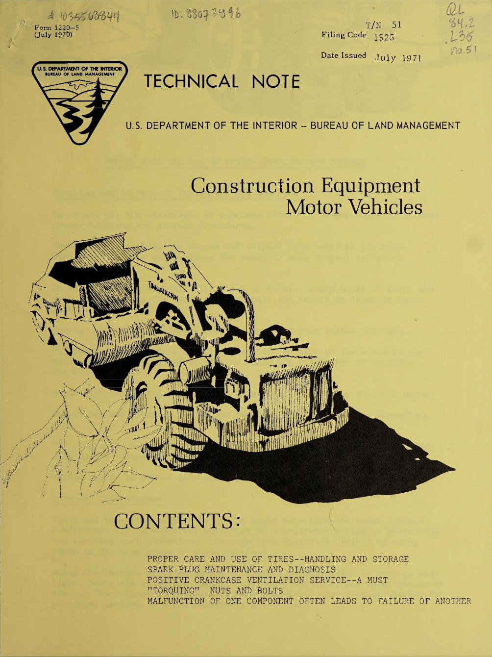
PROPER CARE AND USE OF TIRES—HANDLING AND STORAGE
Handling and Storage of Tubeless Tires and Rims
To obtain all the advantages of tubeless tires, it is necessary to observe proper handling and storage procedures.
Unmounted tires should be stored and shipped in a vertical position. Horizontal storing may compress the beads to make initial inflation difficult.
Do not lift tires by beads with hooks or forks. Sharp hooks or forks may tear, cut, or snag the tubeless tire beads and result in leaks at these point s.
Foreign material or moisture should be removed from inside the tire.
Tubeless rims perform an important function as part of the assembly air seal. Proper care therefore must be taken not to distort or mutilate the rim parts.
Never lift rim by the valve hole. Never drop, tumble, or roll rim parts.
Babbit or lead hammers, not sledge hammers, should be used in assembling rims.
"0" ring seals should be carefully stored in a cool, dry place where they will not be injured or damaged.
Valves should be stored in a cool, dry and clean place.
Tire and Tube Storage
Tires and tubes are subject to rather rapid deterioration under certain conditions. It is essential that they be stored with a view to preventing and limiting such conditions. Storage time should be limited by using tires in the same order they are received.
Among the factors which cause and accelerate deterioration in storage are— light, heat, air in motion, ozone, oils, dust and dirt, and water inside of tires. The following procedure is recommended for tire storage whether for prolonged periods or for a relatively short time.

New Tires
1. Store indoors in a cool, dark, dry area, free from drafts. If indoor storage is impractical, tires may be stored outdoors, providing they are covered with tarpaulins or other opaque waterproof covering. It is abso¬ lutely essential that water and moisture be kept from inside of tires. A good way to achieve this is to mount on wheels, inflate to 50% of oper¬ ating pressure, then cover with tarpaulins.
2. Store away from electrical devices such as motors, or switches, since they are an active source of ozone.
3. Do not store tires in the same or adjoining rooms with gasoline and lubricants. The solids, fluids, or vapors from them are readily absorbed by rubber and cause deterioration.
4. Tubeless tires should not be stacked but should be stored in a vertical position, leaning against post, rack or wall, on the tread. Stacking will tend to deform the tire and force its beads together and produce stains in the rubber which will accelerate weather damage. This may make initial inflation difficult. New tubeless tires are banded to prevent bead defor¬ mity. Do not remove bands prior to mounting.
5. Carbon dioxide fire extinguishers should be provided in tire storage
areas.
Used Tires
1. Clean and carefully inspect before storing. Make all necessary repairs before storing, especially if cord fabric is exposed, as moisture will be absorbed very readily.
2. Observe same storage conditions and cautions as for new tires.
Mounted Tires
1. If necessary to store tires while mounted on vehicle, block up so that the weight does not rest on the tires, and release the air from the tire. Where vehicle cannot be blocked, check air pressure frequently and main¬ tain proper inflation.
2. Each tire should be protected by a cover or wrapping of canvas or similar material.
3. Vehicles on tires should be moved every month or two so that the same section of the tire is not always under strain from deflection.
4. Paint should not be used to preserve tires. If it appears that exposure will be severe consult your tire supplier for additional recommendations.
2

Tubes
1. New tubes should be left in original package. Store in dry, cool, draft-free storage area.
2. Used tubes should be removed from the tire, completely deflated, cleaned, folded and stored in the same manner as new tubes.
Courtesy: Goodyear Tire and Rubber Company

SPARK PLUG MAINTENANCE AND DIAGNOSIS
The spark plug continues to cause misunderstanding among servicemen. In many instances, spark plugs become inoperative because of other defective engine components, and replacement is only a temporary fix, unless the defective engine components are repaired or replaced.
Normal Spark Plug - Normal operating spark plugs are indicated by the presence of light, tan, to brown deposits with normal gap increase of .001 inch per thousand miles of operation or less. If electrodes do not show excessive wear, they may be cleaned and reconditioned as recommended in the following section and be reinstalled with good results.
If replacement is necessary, use the same heat range spark plug.
Troublesome spark plugs can be classified as those which develop a faulty condition during engine operation and cause periodic or continual engine misfire. Troublesome plugs should not be confused with defective plugs since the cause of troublesome spark plugs can generally be traced to defective engine components or specific type of engine operating
conditions.
The best method for detecting troublesome plugs is use of an ignition scope; however, in cases where a scope is not available, plugs can be visually inspected.
Various types of troublesome spark plug conditions and causes are listed
below:
1. Carbon fouling - Carbon fouling is indicated by the presence of black dry fluffy carbon deposits.
Cause: If only one or two spark plugs are carbon fouled, check the following components.
A. High tension leads - check for open circuit condition, high tension resistance, deteriorated or hardened wire insulation.
B. Burnt or sticking valves - if complete set is carbon fouled, check for C., D., and E.
C. Dirty or clogged air cleaner -
D. Improperly operating heat riser -
E. Excessive idling—stop and go type operation -

2. Carbon fouling--oil - Oil fouling is indicated by the presence of wet black deposits.
Cause: This type of fouling can occur in new or rebuilt engines before the piston rings become properly seated and oil control is achieved. However, oil fouling in older engines generally indicates that one or more of the following conditions prevail:
A. Worn piston rings -
B. Worn cylinders -
C. Worn pistons -
D. Worn valve guides -
3. Pre-ignition - Pre-ignition is indicated by melted or very severly burnt center and/or side electrodes, blistered insulator in
aluminum or metallic deposits on the insulator.
Cause: components and/or
Incorrect spark plug heat range or defective engine conditions such as:
A. Burnt valves--low compression.
B. Distributor—over advanced ignition timing.
C. Cooling system—inoperative or partially clogged.
D. Carburetion—lean air fuel, low grade fuel.
E. Detonation—improper octane fuel, low grade fuel.
4. Worn spark plugs - Worn spark plugs are indicated by severly erroded or worn center and side electrodes and light brown to tan deposits on insulator.
Cause: During normal operating conditions, heat together with sulphur and lead compounds wear out the center and side electrodes. Gap growth of .001 inches per 1,000 miles of plug service is considered normal, thus plugs with 10,000 miles of service could have gap growth of +.010
inches.
5. Removing the spark plugs - Disconnect the spark plug wires and loosen each plug 1 or 2 turns using a deep socket wrench of correct size. Removal of the terminal boot should be done by gripping the boot rather than by the spark plug wire. Blow all dirt from around each plug before removal. Remove and rack the plugs--mark the respective cylinders on each plug. Remember the firing tip of the plug can reveal many internal engine .problems and help pinpoint a troublesome cylinder.
2
6. Cleaning the spark plugs - All spark plugs should be thoroughly dried before cleaning in an abrasive type cleaner. The use of compres¬ sed air generally provides suitable results. Spark plugs with an oil fouling condition should be soaked in commercial solvent and then dried.
Spark plugs which are cleaned while in a wet condition will cause abrasive or sand packing in the insulator tip section and/or between the insulator and the shell. After the plugs are installed in the engine, these particles work loose and can cause cylinder wall and piston scuffing. The plugs should be cleaned according to the cleaning instructions provided with the spark plug cleaner.
Note: After the plugs have been cleaned, visually inspect the spark plug firing tip for the fine hairline cracks.
7. Filing and regapping spark plugs - Side electrodes should be opened slightly and both electrode surfaces filed with a distributor point file until the surfaces are flat. The gap surfaces should then be adjusted parallel to each other. The use of a round wire type gauge is recommended as it will permit more accurate setting. Do not apply pressure on the center electrode or insulator tip—only the side electrode is to be adjusted.
3

POSITIVE CRANKCASE VENTILATION SERVICE—A MUST
Many of our fleet vehicles are now equipped with emission control devices usually referred to as positive crankcase ventilation (P.C.V.) or closed crankcase ventilation. These devices, made mandatory in California, are now being installed as standard equipment on all vehicle engines.
At least one manufacturer feels that emission system maintenance is as important as oil and filter changes. In light of this, it seems logical to schedule P.C.V. system maintenance on a regular basis.
Factory recommendations vary as to frequency of service—some say to clean the valves every 6,000 miles and the entire system at 12,000 miles. Others say to inspect the system at intervals of 8,000 miles while other manufacturers recommend inspection twice a year and a valve replacement once a year. Most manufacturers, however, agree that more frequent service may be required where daily mileage is low (10 miles or less), particularly during cold weather.
How can you tell when a system may need service? There are a number of warning signs that indicate a need for service as follows:
1. Crankcase fumes inside the vehicle.
2. Excessive oil or fuel consumption.
3. Fouled spark plugs.
4. Sludge formation inside the engine.
5. Smoking at the filter cap.
6. Rough idle.
7. Short engine life.
t
4. All other major components in the system should be cleaned and inspected. Break all hose connections and blow out lines and components with cleaning solution and air.
5. Fill the system with recommended hydraulic fluid.
6. Operate the equipment, under no load. Cycle each operation several times.
7. Check the filters and strainers. If there is considerable contam¬ ination present, the hydraulic fluid filters should be changed again before putting the machine to work.
8. Discard any oil you have drained from the system. Do not save it for later use.
9. Be sure oil level is correct before putting machine to work.
Some Things To Avoid
Straight kerosene, because it is not compatible with most hydraulic fluids. If you must use kerosene, flush the system thoroughly to clear it all out.
SOLVENTS AND CHEMICAL CLEANERS should be avoided for three reasons.
First, they don’t provide good lubrication for the pump while they are in the system.
Second, solvents and chemical cleaners are hard to get out of the system once they are inside. Even a small trace of commercial chlorinated solvent can practically destroy the extra oxidation resistance of additive-type hydraulic oil.
Third, solvents can become highly corrosive to steel and copper if they remain in the system and should become mixed with water.
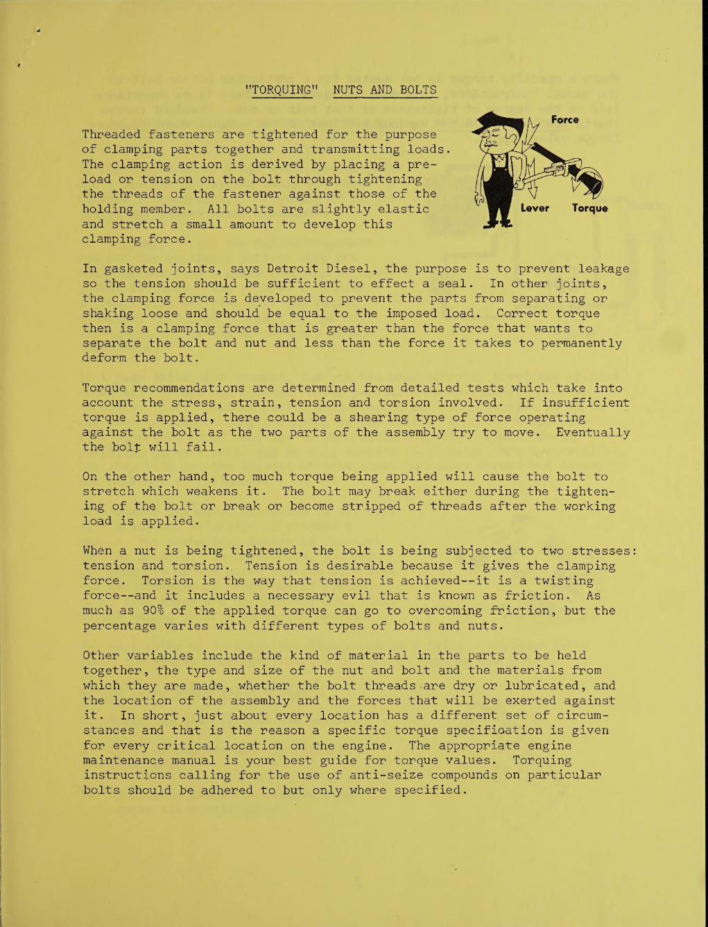
"TORQUING" NUTS AND BOLTS
Threaded fasteners are tightened for the purpose of clamping parts together and transmitting loads. The clamping action is derived by placing a pre¬ load or tension on the bolt through tightening the threads of the fastener against those of the holding member. All bolts are slightly elastic and stretch a small amount to develop this clamping force.
In gasketed joints, says Detroit Diesel, the purpose is to prevent leakage so the tension should be sufficient to effect a seal. In other joints, the clamping force is developed to prevent the parts from separating or shaking loose and should be equal to the imposed load. Correct torque then is a clamping force that is greater than the force that wants to separate the bolt and nut and less than the force it takes to permanently deform the bolt.
Torque recommendations are determined from detailed tests which take into account the stress, strain, tension and torsion involved. If insufficient torque is applied, there could be a shearing type of force operating against the bolt as the two parts of the assembly try to move. Eventually the bolf will fail.
On the other hand, too much torque being applied will cause the bolt to stretch which weakens it. The bolt may break either during the tighten¬ ing of thq bolt or break or become stripped of threads after the working load is applied.
When a nut is being tightened, the bolt is being subjected to two stresses tension and torsion. Tension is desirable because it gives the clamping force. Torsion is the way that tension is achieved—it is a twisting force—and it includes a necessary evil that is known as friction. As much as 90% of the applied torque can go to overcoming friction, but the
percentage varies with different types of bolts and nuts.
Other variables include the kind of material in the parts to be held together, the type and size of the nut and bolt and the materials from which they are made, whether the bolt threads .are dry or lubricated, and the location of the assembly and the forces that will be exerted against it. In short, just about every location has a different set of circum¬ stances and that is the reason a specific torque specification is given for every critical location on the engine. The appropriate engine maintenance manual is your best guide for torque values. Torquing instructions calling for the use of anti-seize compounds on particular bolts should be adhered to but only where specified.
Where a specific torque is not quoted for a particular nut or bolt in
the manual instructions, this does not mean that there is no importance laid on the degree of tighteness of that bolt or nut. Standard torque charts are located in the various sections of the manuals where standard
torque values apply.
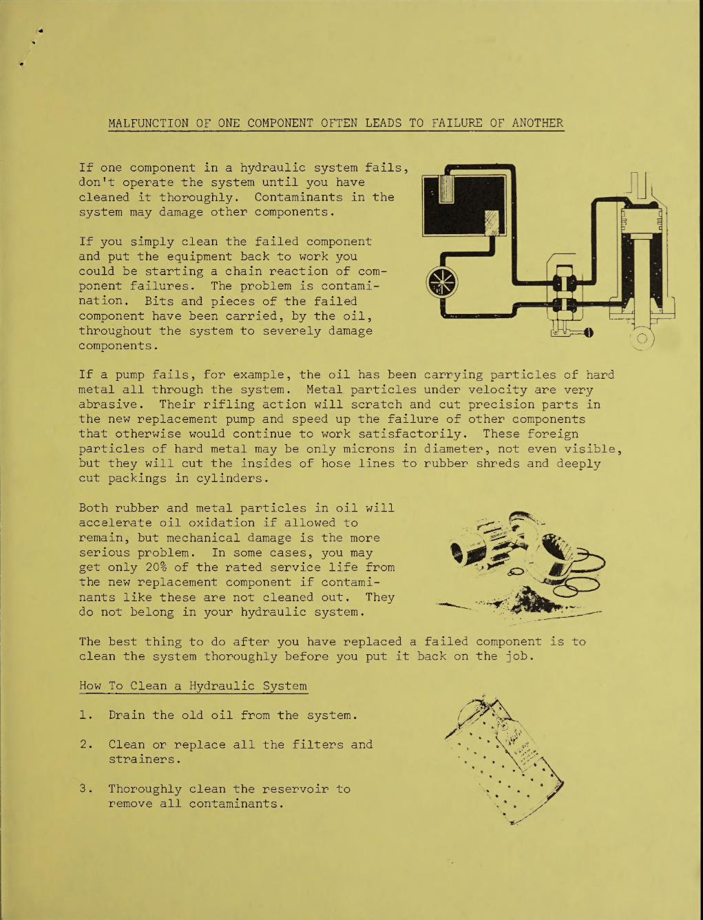
MALFUNCTION OF ONE COMPONENT OFTEN LEADS TO FAILURE OF ANOTHER
If one component in a hydraulic system fails, don’t operate the system until you have cleaned it thoroughly. Contaminants in the system may damage other components.
If you simply clean the failed component and put the equipment back to work you could be starting a chain reaction of com¬ ponent failures. The problem is contami¬ nation. Bits and pieces of the failed component have been carried, by the oil, throughout the system to severely damage components.
If a pump fails, for example, the oil has been carrying particles of hard metal all through the system. Metal particles under velocity are very abrasive. Their rifling action will scratch and cut precision parts in the new replacement pump and speed up the failure of other components that otherwise would continue to work satisfactorily. These foreign particles of hard metal may be only microns in diameter, not even visible but they will cut the insides of hose lines to rubber shreds and deeply cut packings in cylinders.
Both rubber and metal particles in oil will accelerate oil oxidation if allowed to remain, but mechanical damage is the more serious problem. In some cases, you may get only 20% of the rated service life from the new replacement component if contami¬
nants like these are not cleaned out. They do not belong in your hydraulic system.
The best thing to do after you have replaced a failed component is to clean the system thoroughly before you put it back on the job.
How To Clean a Hydraulic System
1. Drain the old oil from the system.
2. Clean or replace all the filters and strainers.
3. Thoroughly clean the reservoir to remove all contaminants.

V


![Title 46 46 MOTOR VEHICLES MOTOR VEHICLESleg.wa.gov/CodeReviser/RCWSelectedTitles/Documents/2017/...(2017 Ed.) [Title 46 RCW—page 1] Title 46 Title 46 46 MOTOR VEHICLES MOTOR VEHICLES](https://img.pdfslide.net/doc/110x75/5b2073857f8b9adb5d8b48fe/title-46-46-motor-vehicles-motor-2017-ed-title-46-rcwpage-1-title-46-title.jpg)