Embed Size (px)
Citation preview
Construction of Autostereograms Taking into Account Object Colors and itsApplications for Steganography
Yusuke Tsuda Yonghao Yue Tomoyuki NishitaThe University of Tokyo
{tsuday,yonghao,nis}@nis-lab.is.s.u-tokyo.ac.jp
Abstract
Information on appearances of three-dimensional ob-jects are transmitted via the Internet, and displaying objectsplays an important role in a lot of areas such as movies andvideo games.
An autostereogram is one of the ways to represent three-dimensional objects taking advantage of binocular paral-lax, by which depths of objects are perceived. In previousmethods, the colors of objects were ignored when construct-ing autostereogram images. In this paper, we propose amethod to construct autostereogram images taking into ac-count color variation of objects, such as shading.
We also propose a technique to embed color informa-tion in autostereogram images. Using our technique, au-tostereogram images shown on a display change, and view-ers can enjoy perceiving three-dimensional object and itscolors in two stages. Color information is embedded ina monochrome autostereogram image, and colors appearwhen the correct color table is used. Our technique can alsobe used for steganography to hide color information. More-over, file size gets smaller than that of an original autostere-ogram image because indexed colors are used. Therefore,the 3D images constructed using our method are useful fortranmission through the cyberworld.
1. Introduction
Three-dimensional objects are displayed for many pur-poses such as research about human vision and represen-tation of virtual objects in movies, and there are a lot ofways to display objects. Depth information is important forthree-dimensional impression, and is usually represented bydisplaying the objects on the screen using perspcetive pro-jection. An autostereogram is one of the ways to representthree-dimensional objects by ordinary display devices tak-ing advantage of binocular parallax which plays an impor-tant role in depth perception.
In the previous methods, color autostereogram imageshave not taken into account the objects’ colors. Therefore,
q
(a) SS-relation (b) OS-relation
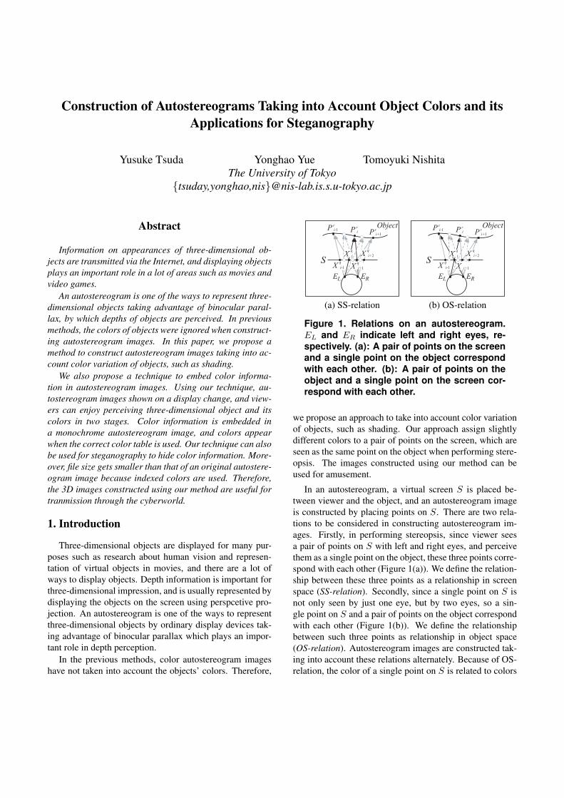
Figure 1. Relations on an autostereogram.EL and ER indicate left and right eyes, re-spectively. (a): A pair of points on the screenand a single point on the object correspondwith each other. (b): A pair of points on theobject and a single point on the screen cor-respond with each other.
we propose an approach to take into account color variationof objects, such as shading. Our approach assign slightlydifferent colors to a pair of points on the screen, which areseen as the same point on the object when performing stere-opsis. The images constructed using our method can beused for amusement.
In an autostereogram, a virtual screen S is placed be-tween viewer and the object, and an autostereogram imageis constructed by placing points on S. There are two rela-tions to be considered in constructing autostereogram im-ages. Firstly, in performing stereopsis, since viewer seesa pair of points on S with left and right eyes, and perceivethem as a single point on the object, these three points corre-spond with each other (Figure 1(a)). We define the relation-ship between these three points as a relationship in screenspace (SS-relation). Secondly, since a single point on S isnot only seen by just one eye, but by two eyes, so a sin-gle point on S and a pair of points on the object correspondwith each other (Figure 1(b)). We define the relationshipbetween such three points as relationship in object space(OS-relation). Autostereogram images are constructed tak-ing into account these relations alternately. Because of OS-relation, the color of a single point on S is related to colors

of two corresponding points on the object, however is as-signed irrelevant to the colors of the points on the object inprevious methods.
In this paper, we propose a method to determine the colorof points on S. Although a pair of points on S has an SS-relation with a point on the object, such points on S alsohave OS-relations with other points on the object. There-fore, in our method, slightly different colors are assigned toa pair of points on S which have SS-relation. The allowabledifferences of colors are determined by an user test. We alsoconsider the limitation of representation of colors because itis expected that object colors with wide variety are difficultto be represented in autostereogram images.
We also propose a method to apply color autostereogramimages to the amusement of color emergence. Two-stageperceptions of three-dimensional object and its colors areamusing. In the first stage, a sand storm like autostereogramimage is displayed. This image has color information incolor index, but colors are not displayed because a dummycolor table is embedded in. In the second stage, color au-tostereogram image is displayed by using correct color ta-ble. It is amusing that monochrome object and color objectcan be perceived in two stages. In addition, our technique isa kind of steganography in the sense that the existence of in-formation about object colors are hidden. Color informationcan be transmitted only to those who should receive colorinformation by taking advantage of our method. Moreover,since indexed colors are used to encode the autostereogramimages, file size is reduced from original file size.
The rest of this paper is composed as follows. Relatedwork is described in Section 2. Section 3 reviews pre-vious methods constructing monochrome autostereograms.We describe the algorithm to determine colors of autostere-ogram images in Section 4. An algorithm to embed color in-formation in autostereogram images, and to construct colortables used as encryption keys is described in Section 5. Weshow the results in Section 6, and describe conclusion andfuture work in Section 7.
2. Related work
Wheatstone [14] invented stereoscopes, by which twoimages drawn or taken from slightly different angles are re-spectively projected to each eye. David Brewster [1] builtstereo cameras, by which two pictures of scenes can betaken. Stereogram images, which consist of a pair of pho-tographs or images are called stereo pair, and view anglesof the images can not be wide because it becomes diffi-cult to perform stereopsis when two points on the image,which are to be seen as the same point on the object, aretoo separated. Gabor [5] invented holography taking ad-vantage of the interference between beams. Holography isa technique to produce a hologram, which is a kind of pho-
(a) (b)
Figure 2. Random Dot Stereograms showinga teapot: (a) a stereo pair, and (b) an au-tostereogram. Methods to perform stereop-sis are explained in Section 3.2.
tograph with three-dimensional information recorded in.Holograms were first created by Denisyuk [4] in 1962, andlater by Leith and Upatnieks [8] in 1962. Except for stereopairs, all the methods discussed above need special devicesto record information or to view three-dimensional objects.
Julesz [6] invented Random Dot Stereogram (RDS),which is a technique to construct a pair of images consistingof random dots (Figure 2(a)). Tyler et al. [13] combineda pair of random dot images into a single image, and cre-ated Single Image Random Dot Stereogram (SIRDS) (Fig-ure 2(b)). SIRDS is a form of autostereogram or single-image stereogram (SIS), and view angles of autostereogramimages can be wide. Kinsman [7] showed a method to cre-ate colored autostereograms from a depth map and a patternimage. His method was based on orthogonal projection. Inhis method, pattern images are distorted according to depthmaps and are tiled horizontally, and colors of the objects areout of consideration. In the previous autostereograms, ex-actly the same color is assigned to a correlated pair of pointson the image. This is because, in autostereograms, two ormore horizontal points on the image tend to have correlationwith each other due to the SS-relation and the OS-relation,and two of the correlated points on the image are thought tobe seen as the same point on the object only when they sharethe same color. Our method improves autostereograms totake into account color variation of objects.
Recently, a lot of methods are researched to improve theperformance in the construction of SIRDS. Thimbleby etal. [12] showed an algorithm based on the perspective pro-jection. Yu et al. [15] created a fast and memory savingalgorithm based on ray-tracing. Petz et al. [11] introducedan algorithm which is suited for hardware-acceleration andsucceeded in constructing SIRDS images at real time.
Applications of stereograms are also searched. Omoriet al. [10] analyzed the recognition of stereoscopic imagesamong elderly people using stereogram images on liquidcrystal display and papers. Dadson [3] described the toolsfor evaluation of stereoscopic camera systems using RDSbuilt with ray tracing. Liu et al. [9] developed a systemto display trajectories of particles on stereogram images.Stereograms also appear on books for amusement [2].

3. Constructing and viewing autotereograms
In this section, we first review the methods to con-struct autostereogram images, and then review the viewingmethod to perform stereopsis.
3.1. Construction of autostereograms
Figure 1(a) is an illustration where a human is lookingat an object. In this figure, EL and ER indicate human’sleft and right eyes, respectively, and S is a virtual screenbetween the human and the object. Information about theobject is recorded on S by placing points on S.
Generally, in constructing autostereogram images, cal-culation is done in each scanline, sequentially. A singlescanline is composed of many sequences of points Xq
i (qis the sequence number, and i is the point number in thesequence q). A sequence of points Xq
i is determined as fol-lows. Firstly, the initial point Xq
0 on the scanline is selected.Xq
0 is normally the first pixel on the left of the scanline.Secondly, the location of P r
0 , where the line of sight fromEL to Xq
0 intersects with the object, is calculated. Then Xq1 ,
which is the intersection point of S and the line of sight fromER to P r
0 , is calculated. Here, Xq0 and Xq
1 correspond tothe point P r
0 on the object, and the depth of P r0 is converted
into the distance between Xq0 and Xq
1 . We call the relationestablished between such three points, the SS-relation. Inthe same way, P r
1 , which is the intersection point of the ob-ject and the line of sight from EL to Xq
1 is determined, andXq
2 , which is the intersection point of S and the line of sightfrom ER to P r
1 is also determined. Here again, Xq1 and Xq
2
also have an SS-relation with the point on the object P r1 .
The sequence of points Xqi is then determined by repeating
the same calculation.In this way, a sequence of points is determined from one
initial point, and another sequence of points Xq′
i is deter-mined using another initial point Xq′
0 . Note that when asufficient number of sequences of points are determined, allpixels on the scanline belong to either sequence. By ran-domly selecting a certain number of initial points and byskipping the process starting from those points, some pointson the screen remain blank. At a glance the resulting imagelooks like random dots (Figure 2(b)), but the depth of theobject can be perceived by performing stereopsis. Note thatin previous methods, the object colors are not taking intoaccount when plotting the points on the screen.
3.2. Viewing images stereoscopically
In this paper, we indicate a single pair of points on theimage by two white squares to help stereopsis (Figures 2, 6,8, 9 and 10).
For stereopsis, the viewer has his eyes unfocused bygazing blankly at the image or by crossing his eyes. Two
squares are seen to be four squares, the two of which areseen from the left eye, and the others are seen from theright eye. By adjusting eyes so that the center two of thesefour squares are seen at the same position, the eyes are fo-cused on the object in the autostreogram image, and three-dimensional impressions can be perceived. It will be diffi-cult to perform stereopsis for the first time, but it is said thatonce succeeded, it becomes easy to perform stereopsis.
The method by gazing blankly at the image is calledparallel-viewing method, and the method by having eyescrossed is called cross-viewing method. The perceiveddepth of the objects are reversed depending on the method,because lines of sight from two eyes cross in front of theimage in the former method, and cross behind the image inthe latter method. In this paper, all of the autostereogramimages are constructed for parallel-viewing method.
4. Calculation of colors on autostereograms
In our method, we determine the colors of the points ineach sequence q on the screen, taking the OS-relation intoaccount. Due to the OS-relation, a single point on the screencorresponds to two points on the object, which means thatthe color of the point on the screen should take into ac-count the colors of the two points on the object. On theother hand, due to the SS-relation, a single point on the ob-ject corresponds to two points on the screen. Our idea isto assign slightly different colors to such two points on thescreen to take into account the OS-Relation, although theycorrespond to a single point on the object. Since we assigndifferent colors, if they differ too much, then it is likely thatthe stereopsis becomes difficult because the left eye and theright eye would observe different colors for a single point.Therefore, we conducted an user test to know the allowedmaximum difference in colors as described in Section 4.1.The solution to determine the colors of the points on thescreen is described in Section 4.2. In our method, colors arecalculated in L*u*v* color space, which is explained in Ap-pendix. We use this color space because difference of colorshuman perceives can be measured more correctly when thedifferences of colors are small. A technique that facilitatesthe stereopsis is described in Section 4.3.
4.1. User test for restriction of colors
When two colors of a pair of SS-related points on thescreen are similar, it is easy to perform stereopsis. On theother hand, if the two colors differ too much, it becomesdifficult. Amounts of color differences seem to vary de-pending on luminance values. Therefore, we performed anuser test to determine the allowable color difference of apair of points on the screen which are perceived to be thesame point on the object when performing stereopsis. As

(a) (b)
Figure 3. Autostereogram images used in theuser test: Color difference between squareplane and background is small in (a), and islarge in (b).
expected, we obtained data of the allowable amounts ofcolor differences which differ with luminance values. Wetake into account the personal difference when creating anautostereogram, by using the obtained data from the targetuser. To construct autostereogram images in this paper, weused the average of values obtained from all users.
In the user test, users view an autostereogram imageshown in Figure 3 stereoscopically. A square plane and abackground can be perceived in the autostereogram image.Either of the square plane or the background is displayedin one color, respectively, and dots with various colors areplaced on the square and background so that sterepsis can beperformed. The set of dots indicates the SS-related pointson the screen. (Note that because of the resolution, the dotsshown in Figure 3 may be inconspicuous.)
In the left and right sides of the square, it happens thatone eye is seeing a point on the square while the other eye isseeing a point from the background. If colors of the squareplane and the background are similar enough, then it is easyto perform stereopsis, otherwise, it becomes difficult.
The color values of the background in L*u*v* colorspace and L* value of the square plane are randomly cho-sen from about 1000 sets of colors prepared beforehand, andthe u* and v* values of the square plane are determined byusers. Users search the crude boundary value between anallowable and not allowable state, and report us the value.Depending on the set of color values, it may be difficult toperform stereopsis for all the u* and v* values of the squareplane. In such a case, users report us that it is impossibleto perform stereopsis for the values. After the user finishedfor one set of colors, the colors are changed to the next set.
From the user test, we obtain a set of pairs of two colors(the color of the square, and the color of the background) inthe L*u*v* space. We calculate the Euclidean distance be-tween the two colors in each pair, and gather the distancesfor each L* value (the L* value is discretized and rangesfrom 0 to 100). Note that a single distance is gathered twicefor both the L* values of the two colors. Finally, we averagethe distances for each L* value, and obtain a relationshipbetween the L* value and the allowed color difference forthat value. In the above process, we have assumed that the
Figure 4. The amounts of allowable distancesin L*u*v* color space: Blue and green dotsindicate the data of the widest ranges of al-lowable differences and the data of the nar-rowest. Red dots indicate the average data.Data obtained from two-thirds of all users arearound the average data. L∗
ave is the meanamount of L∗ values of two colors of thesquare and the background.
L*u*v* is locally uniform, that is, if a color is reported to besufficiently close to another color in the context of perform-ing stereopsis, then the colors that are closer to the formerone measured in the Euclidean space are all assumed to beclose enough for performing stereopsis. We could removethis assumption by testing larger number of sets of colors,but such an user test would be a very hard task for the user,thus we gave up such an approach.
As expected, the value of allowable color difference de-pends on colors. Most of users remark that it becomes dif-ficult to allow the difference or to perform stereopsis if theluminance is high. This is because, in L*u*v* color space,it gets difficult to distinguish one color from another whenluminance is low. Figure 4 shows the relationship betweenluminance and the allowable distance. The horizontal axisshows the average luminance of the colors of the squareand the background 1
2 (L∗1 + L∗
2), where (L∗1, u
∗1, v
∗1) and
(L∗2, u
∗2, v
∗2) are three-dimensional values of the two points
in L*u*v* color space. The vertical axis shows the allow-able distance, t((L∗
1 + L∗2)/2). It turns out that differences
among individuals can not be ignored and that large amountof difference tend to be allowed if the L* value is low.
4.2. Equations of color calculation
According to the algorithm to construct autostereogramshown in Section 3.1, we determine the sequences of pointson a scanline, and each pair of adjacent two points has SS-relation. In the proposed method, slightly different colorsare assigned to such points taking into account the colors ofcorresponding points on the object.
Figure 1(a) shows the relationship between points on theobject and points on the autostereogram image. In this fig-

ure, P ri indicates a point on the object and Xq
i indicates apoint on the autostereogram image.
Two conditions are taken into account when calculatingcolors on autostereogram images.
The first condition is that the color of Xqi on the object is
sufficiently similar to the colors of the corresponding pointsP r
i−1 and P ri , such that,
∣∣∣c(Xq
i ) − c(P ri−1)
∣∣∣ ≤ t(l(P r
i−1))/2, and∣∣∣c(Xq
i ) − c(P ri )
∣∣∣ ≤ t(l(P r
i ))/2,
(1)
where c is a function which returns the color of the pointand t is an arbitrary function to return allowable color dif-ference. l is a function to return L* value of the point, andt(c(P r
i )) seems to be more accurate than t(l(P ri )), but we
employ t(l(P ri )) to use the result of the user test. From
equation (1),
∣∣∣c(Xq
i ) − c(Xqi+1)
∣∣∣≤
∣∣∣c(Xqi ) − c(P r
i )∣∣∣ +
∣∣∣c(Xqi+1) − c(P r
i )∣∣∣
≤ t(l(P r
i ))/2 + t
(l(P r
i ))/2 = t
(l(P r
i )),
(2)
is concluded thus the function obtained from the user testcan be used for the function t.
The second condition is that differences between the col-ors of the object and the colors expected to be perceivedwhen performing stereopsis should be as small as possible,as shown below,
min
n−1∑i=1
|Di|2, (3)
where n is the number of points in the point sequence q,and variable Di is the difference between the mixed color12
(c(Xq
i ), c(Xqi+1)
)and its corresponding object color
c(P ri ) , and is shown below,
Di =12
(c(Xq
i ) + c(Xqi+1)
)− c(P r
i ). (4)
We assume that the color perceived in performing stere-opsis is the mean color of the two points’ color because amixed color of two colors is approximately on the straightline between these two colors in L*u*v* color space. Theabsolute value of Di should be small, in order that colorssimilar to the object can be perceived when stereopsis isperformed.
We determine colors of pixels on autostereogram imagesby solving optimization problem taking into account equa-tions (1), (2) and (3). There are some methods to solve the
Figure 5. Changing L* values: The L* valuesof points on the object corresponding to thepoints in a sequence q, which is defined inSection 3, are changed to the same extent.
(a) (b)
Figure 6. Facilitating stereopsis: Both of theautostereogram images (a) and (b) show a ta-ble, and each center of the image is enlarged.(b) is easier to be viewed stereoscopicallythan (a).
optimization problem, such as the quadratic programming.However, for fast calculation, we employed the least squaremethod, and weakened the conditions as shown below,
Bi =|c(Xq
i ) − c(P ri−1)|
t(l(P ri−1))
,
Ci =|c(Xq
i ) − c(P ri )|
t(l(P ri ))
, and
min( n∑
i=1
α(B2
i + C2i
)+
n−1∑i=1
(1 − α)
∣∣∣Di
∣∣∣2t̄
),
(5)
where t̄ is the mean value of the function obtained from theuser test. The constant α indicates the ratio between the in-fluences of two conditions discussed above, and runs from0 to 1. If α is close to 0, the second condition gets influen-tial and more accurate colors are perceived when stereopsisis performed. However, the first condition is less influentialand it becomes difficult to perform stereopsis. On the otherhand, if α is close to 1, it becomes easy to perform stereop-sis, but less accurate colors are perceived when stereopsis isperformed.
The value of α should be as small as possible in the rangethat streopsis is easy to perform. We determined the value ofα by comparing autostereogram images constructed usingvarious α values. It seems that stereopsis is easy to performand colors are well represented when α is about 0.4. We

(a) (b)
Figure 7. The autostereogram images (left) and the corresponding color tables (right): (a) is anautostereogram image displayed with a dummy color table. (b) with correct color table.
constructed all color autostereogram images in this paperusing the α value of 0.4 except as otherwise noted.
4.3. Facilitating stereopsis
Since colors of neighboring points on autostereogramimages tend to be similar, it is difficult to perceive eachpoint individually, thus making the stereopsis hard. Figure6 (a) shows the results of color calculation, and is difficultto be viewed stereoscopically. Therefore, we changed theL* values of the points on the object to inform the positionsof the points to be seen as the same (Figure 6 (b)).
The L* values are changed as stated below. As shownin Section 3.1, the positions of the points in the sequenceson the autostereogram image are calculated. The L* valuesof the points on the object, which correspond to the pointsin a sequences on the image, are chaged to the same extent(Figure 5). These values are changed randomly so that theaverage of the L* values of all points on the object is main-tained constant, and the amounts of the change in L* valuesare below certain threshold. We changed the L* values inthe range of ± 16 from the original values, except as other-wise noted. After changing the L* values of points on theobject, colors on the autostereogram image are calculatedas shown in Section 4.2.
5. Color embedding and its applications
In this section, we propose a technique to embedcolor information in autostereogram images, and pro-pose applications of this technique. Using our technique,monochrome object and color object can be perceived intwo stages. As applications, our technique can be usedfor amusement and steganography. An autostereogram im-age has dummy color table, so monochrome image like theautostereogram of Figure 7(a) is displayed. By replacingdummy color table with correct one, color image like theautostereogram of Figure 7(b) is displayed.
The process of embedding color information and con-structing color tables is performed as a post-process to thecreation of color autostereogram described in Section 4.2.The colors of the images are indexed and the images are
saved in a common file format that allows indexed colors,such as BMP or GIF. Note that the maximum number ofindexed colors in those file formats are usually 256.
We randomly classify the sequences of points on the im-age into two sets. If we let the points in one set to be allblack and the points in the other set to be all white, then theresulting image would be a monochrome autostereogram(Figure 8(a)). On the other hand, by assigning 128 colorsto both the sets, we obtain the color autostereogram (Figure8(b)). Therefore, we first reduce the colors used in both setsto 128, and then assign a color index to each point in thesets. The dummy color table is created by assigning blackcolor to the points belonging to one set and white color tothe points belonging to the other set.
5.1. Application for amusement
By using autostereogram images with the color infor-mation embedded in, two stage perception can be enjoyedand thus is applicable to amusement. Users have bothof an autostereogram image and the correct color table.Firstly, users view the image stereoscopically, and perceivea monochrome object. Secondly, users replace the dummycolor table with the correct one, and object colors appear. Inthis way, viewers can enjoy perceiving monochrome objectand its color in two stages.
5.2. Application for steganography
Autostereogram images created using our technique area kind of steganography in the sense that the existence of thecolor information itself is hidden. By utilizing the correctcolor table as the encryption key, our technique can alsobe applied to steganography. An autostereogram image issent to intended recipient through the Web. Only those whohave the correct color table can view color autostereogramimages and perceive color variation of objects.
6. Results
We show some color autostereogram images constructedusing our method. Color objects to be perceived in au-tostereogram images are shown in upper right of the images,

(a) (b) L∗ave = 40 (c) L∗
ave = 60 (d) α = 0.10 (e) α = 0.90
Figure 8. Experiments on color autostereograms: (a) a square, (b) and (c) a teapot, (d) and (e) a dol-phin. In (a), even if vertical color differences are large, ghosts do not get conspicuous. The averageof L∗ value of all pixels in (b) is 40 and that in (c) is 60, and (b) is easier to view stereoscopically than(c). (d) and (e) are constructed using different values of α.
and two white squares exist near the center of each imageto help stereopsis in Figures 8, 9 and 10.
Since allowable color differences of two points on theimage to be seen as the same point on the object are notwide, there is a limitation of horizontal color variation ofautostereogram images. If colors of dots on the same scan-line vary much, wispy colors of the objects are seen aroundthe object, and false objects are perceived. We call thesefalse objects ghosts in this paper. On the other hand, even ifvertical color differences are large, it does not become diffi-cult to perform stereopsis and ghosts do not get conspicuous(Figure 8 (a)).
As stated in Section 4.2, the allowable differences of col-ors are large if the L* value is low. In Figure 8 (c), ghostsseen around the teapot is more conspicuous and it is moredifficult to perform stereopsis than in Figure 8 (b) becauseof the allowable color difference.
Figures 8 (d) and (e) are constructed using different val-ues of α. Figure 8 (d) is constructed using the α value of 0.1,and is difficult to view stereoscopically. (e) is constructedusing the α value of 0.9, and is easy to view stereoscopi-cally, but less accurate colors are perceived.
In Figure 9, we show autostereogram images constructedunder condition that L* value is low and colors are calcu-lated using the α value of 0.4. This condition seems to bebetter to construct autostereogram images, which are easyto be viewed stereoscopically, and color variation is wellrepresented. Color variation of objects, especially shading,can be perceived in these images.
We also created an animation of autostereogram. It ismuch more fun to perceive moving objects than still objects.It takes about 0.7 seconds to create a single 1000 × 600pixel autostereogram image using a machine with Intel Core2 Extreme 3.0 GHz CPU and 8 GB memory.
We also succeeded in steganography. When the imagefile is opened without an encryption key, monochrome au-tostereogram image as shown in Figure 7 (a) is displayed.Only those who know that these images are not corruptedbut are autostereogram images can perceive the shapes ofthe objects, and only those who have the true color tablecan perceive the object colors as shown in Figure 8(b).
(a) (b)
Figure 10. The autostereogram images show-ing a table: (a) with 24 bits colors and (b)with 256 indexed colors. Color variation islost only a little.
Figure 10 (a) is a color autostereogram image with 24bits colors, and Figure 10 (b) with 256 indexed colors. Be-cause of the limitation of color variation in autostereogramimage, loss of color variation is little. An 8-bits color tableis used to construct Figure 10 (b), and can be viewed stereo-scopically. In addition, the size of file is reduced from thatof original file because the colors are indexed.
7. Conclusions and future work
We have proposed a method to construct autostereogramimages taking into account object colors, which have notbeen constructed previously. To assign colors, we consid-ered following two conditions. First, the differences be-tween the colors of the object and the colors perceived whenperforming stereopsis are as small as possible. Second,the color differences between any two points on the im-age, which have an SS-relation, are small enough to per-form the stereopsis. The second condition are consideredalso by using the data from the user test. Ratio between theinfluences of these two conditions are determined by exper-iments. Using our method, color variation, especially shad-ing of objects, can be represented in autostereogram images.A limitation is that the objects whose colors vary much hor-izontally, are difficult to be represented. On the other hand,we have found characteristics of color objects, which areeasy to be represented in autostereogram images. Objectswhose L* values are low tend to be comparatively naturallyperceived in autostereogram images. We have also createdan animation composed of autostereogram images in which

(a) table (b) dolphin (c) teapot
Figure 9. The autostereogram images constructed under the conditions of low L* value, and α valueof 0.4: (a) shows a table, (b) shows a dolphin and (c) shows a teapot.
colored objects’ movements can be perceived.We also succeeded in embedding color information in
autostereogram images. It is amusing that monochrome au-tostereogram images become color ones when the true colortable is used. Moreover, autostereogram images can be ap-plied for steganography to hide color information by usingcolor table as an encryption key.
As future work, autostereogram images showing objectswith wider ranges of color variation are considered to beconstructed by taking advantage of the fact that colors ofneighboring points are seen to be mixed. Moreover, col-ors printed on paper are a little different from those shownon displays. Such difference should be taken into accountwhen printing color autostereogram images created usingour method.
References
[1] http://www.stereoscopy.com/library/waack-ch-2.html.
[2] Andrews and McKeel. Magic Eye: A New Way of Lookingat the World. A Universal Press Syndicate Company, KansasCity, USA, 1993.
[3] C. F. Dadson. Random dot stereograms generated with raytracing as a visualization tool for evaluating stereoscopiccamera systems. SPIE Stereoscopic Displays and VirtualReality Systems X, 5006:10–18, 2003.
[4] Y. N. Denisyuk. On the reflection of optical properties ofan object in a wave field of light scattered by it. DokladyAkademii Nauk SSSR, 114:1275–1278, 1962.
[5] D. Gabor. A new microscopic principle. Nature, 161:777–778, 1948.
[6] B. Julesz. Foundation of Cyclopean Perception. Universityof Chicago Press, 1971.
[7] A. A. Kinsman. Random Dot Stereograms. KinsmanPhysics, 1992.
[8] E. N. Leith and J. Upatnieks. Reconstructed wavefronts andcommunication theory. Journal of the Optical Society ofAmerica, 52:1123–1130, 1962.
[9] H.-T. Liu, M. A. Weissman, G. B. White, G. E. Miner, andW. T. Gustafson. Stereoscopic system for measuring particletrajectories past an underwater model. SPIE StereoscopicDisplays and Virtual Reality, 2177:232–242, 1994.
[10] M. Omori, T. Watanabe, M. Miyao, Y. Sato, and S. Ishihara.Recognition of stereogcopic images among elderly people.SPIE Human Vision and Electronic Imaging VII, 4662:465–473, 2002.
[11] C. Petz, B. Goldlucke, and M. Magnor. Hardware-accelerated autostereogram rendering for interactive 3d vi-sualization. SPIE Stereoscopic Displays and Virtual RealitySystems X, 5006:359–366, 2003.
[12] H. Thimbleby, S. Inglis, and I. Witten. Displaying 3d im-ages: Algorithms for single-image random-dot stereograms.IEEE Computer, 27(10):38–48, 1994.
[13] C. W. Tyler and M. B. Clarke. The autostereogram.SPIE Stereoscopic Displays and Applications, 1258:182–196, 1990.
[14] C. Wheatstone. Contributions to the physiology of vision.-part the first. on some remarkable, and hitherto unobserved,phenomena of binocular vision. Philosophical Transactionsof the Royal Society of London, 128:371–394, 1838.
[15] B. T. Yu and W. W. Yu. Single-image random-dot stere-ogram by crosstalk. SPIE Vision Geometry IV, 3168:115–122, 1997.
Appendix. L*u*v* color space
L*u*v* color space consists of three axes, L*, u* and v*.The L* axis indicates the luminance, and the u* and v* axesindicate red-green color and yellow-blue color, respectively.
We calculated the values of the colors in this color spacebecause it is constructed so that the distance of two pointsin this color space approximates the difference of colors thehuman perceives very well.
The color difference d(Ci, Cj) between the colors Ci
and Cj in this space is calculated by the Euclidean distance,
d(Ci, Cj) =√
∆L∗2 + ∆u∗2 + ∆v∗2, (6)
where each variable is defined as follows,
Ci = (L∗i , u
∗i , v
∗i ), Cj = (L∗
j , u∗j , v
∗j ),
∆L∗ = |L∗i − L∗
j |, ∆u∗ = |u∗i − u∗
j |, and (7)∆v∗ = |v∗
i − v∗j |.