Embed Size (px)
Citation preview

Chapter 3
Containing UndergroundNuclear Explosions
.
CONTENTSPage
INTRODUCTION . . . . . . . . . . . . . . . . . . . . . . . . . . . . . . . . . . . . . . . . . . .WHAT HAPPENS DURING AN UNDERGROUND NUCLEAR
Microseconds . . . . . . . . . . . . . . . . . . . . . . . . . . . . . . . . . . . . . . . . . . . . . .Milliseconds . . . . . . . . . . . . . . . . . . . . . . . . . . . . . +. . . . . . . . . . . . . . . . .Tenths of a Second . . . . . . . . . . . . . . . . . . . . . . . . . . . . . . . . . . . . . . . . .A Few Seconds . . . . . . . . . . . . . . . . . . . . . . . . . . . . . . . . . . . . . . . . . . . .Minutes to Days . . . . . . . . . . . . . . . . . . .. .. .. .. .. .. .. ... ........
EXPLOSION . . . . . . . . . . . . . . . . . . . . .. . . . . . . . . . . . . . . . . . . . .. . . . . . . . . . . . . . . . . . . . .. . . . . . . . . . . . . . . . . . . . .. . . . . . . . . . . . . . . . . . . . .
WHY NUCLEAR EXPLOSIONS REMAIN CONTAINED ... ...... . . . . . . . . . . . . . . . .SELECTING LOCATION, DEPTH, AND SPACING: . . . . . . . . . . . . . . . . . . . . . . . . . . . . . .REVIEWING A TEST SITE LOCATION . . . . . . . . . . . . . . . . . . . . . . . . . . . . . . . . . . . . . . . . . . .CONTAINMENT EVALUATION PANEL . . . . . . . . . . . . . . . . . . . . . . . . . . . . . . . . . . . . . . . . .CONTAINING VERTICAL SHAFT TESTS . . . . . . . . . . . . . . . . . . . . . . . . . . . . . . . . . . . . . . .CONTAINING HORIZONTAL TUNNEL TESTS . . . . . . . . . . .. .. .. .. .. .. ... ... ......TYPES OF RADIATION RELEASES . . . . . . . . . . . . . . . . . . . . . . . . . . . . . . . . . . . . . . . . . . . . . .
Containment Failure: . . . . . . . . . . . . . . . . . . . . . . . . . . . . . . . . . . . . . . . . . . . . . . . . . . . . . . . . . . . .Late-Time Seep . . . . . . . . . . . . . . . . . . . . . . . . . . . . . . . . . . . . . . . . . . . . . . . . . . . . . . . . . . . . . . . .Controlled Tunnel Purging . . . . . . . . . . . . . . . . . . . . . . . . . . . . . . . . . . . . . . . . . . . . . . . . . . . . . .Operational Release . . . . . . . . . . . . . . . . . . . . . . . . . . . . . . . . . . . . . . . . . . . . . . . . . . . . . . . . . . . .
RECORD OF CONTAINMENT . . . . . . . . . . . . . . . . . . . . . . . . . . . . . . . . . . . . . . . . . . . . . . . . . . . .Containment Evaluation Panel . . . . . . . . . . . . . . . . . . . . . . . . . . . . . . . . . . . . . . . . . . . . . . . . . . .Vertical Drill Hole ’lasts . . . . . . . . . . . . . . . . . . . . . . . . . . . . . . . . . . . . . . . . . . . . . . . . . . . . . . . .Horizontal Tunnel Tests . . . . . . . . . . . . . . . . . . . . . . . . . . . . . . . . . . . . . . . . . . . . . . . . . . . . . . . . .From the Perspective of Human Health Risk . . . . . . . . . . . . . . . . . . . . . . . . . . . . . . . . . . . . .
A FEW EXAMPLES: . . . . . . . . . . . . . . . . . . . . . . . . . . . . . . . . . . . . . . . . . . . . . . . . . . . . . . . . . . . .IS THERE A REAL ESTATE PROBLEM AT NTS? . . . . . . . . . . . . . . . . . . . . . . . . . . . . . . . .TIRED MOUNTAIN SYNDROME? . . . . . . . . . . . . . . . . . . . . . . . . . . . . . . . . . . . . . . . . . . . . . . . .HOW SAFE IS SAFE ENOUGH? . . . . . . . . . . . . . . . . . . . . . . . . . . . . . . . . . . . . . . . . . . . . . . . . . .
Box3-A. Baneberry . . . . . . . . . . . . .
Figure
. . . .
3-1.3-2.3-3.3-4.3-5.3-6.3-7.3-8.3-9.
3-10.4
31323232323232
35373840414646464747474748484949515154
Page. . . . . . . . . . . . . . . . . . . . . . . . . . . . . . . . . . . . . . . . . . . . . . . 33
FiguresPage
Formation of Stress “Containment Cage” . . . . . . . . . . . . . . . . . . . . . . . . . . . . . . . . . . . . .Minimum Shot Separation for Drill Hole Tests . . . . . . . . . . . . . . . . . . . . . . . . . . . . . . . .Minimum Shot Separation for Tunnel Tests . . . . . . . . . . . . . . . . . . . . . . . . . . . . . . . . . . . .“Typical’’ Stemming Plan . . . . . . . . . . . . . . . . . . . . . . . . . . . . . . . . . . . . . . . . . . . . . . . . . . . .Three Redundant Containment Vessels . . . . . . . . . . . . . . . . . . . . . . . . . . . . . . . . . . . . . . . .Vessel I . . . . . . . . . . . . . . . . . . . . . . . . . . . . . . . . . . . . . . . . . . . . . . . . . . . . . . . . . . . . . . . . . . . .Vessel 1 Closures . . . . . . . . . . . . . . . . . . . . . . . . . . . . . . . . . . . . . . . . . . . . . . . . . . . . . . . . . . .Tunnel Closure Sequence . . . . . . . . . . . . . . . . . . . . . . . . . . . . . . . . . . . . . . . . . . . . . . . . . . . .Typical Post-Shot Configuration . . . . . . . . . . . . . . . . . . . . . . . . . . . . . . . . . . . . . . . . . . . . .Radius of Decrease in Rock Strength . . . . . . . . . . . . . . . . . . . .. .. ... ... ....... . . . . .
35383941424344454653
Table Page3-1. Release From Underground Tests . . . . . . . . . . . . . . . . . . . . .. .. .. . .. .. .. . . . .. .......8 48

Chapter 3
Containing Underground Nuclear Explosions
Underground nuclear tests are designed and reviewed for containment, with redundancy andconservatism in each step.
INTRODUCTIONThe United States’ first underground nuclear test,
codenamed ‘‘ Pascal-A,’ was detonated at the bot-tom of a 499-foot open drill-hole on July 26, 1957.1
Although Pascal-A marked the beginning of under-ground testing, above ground testing continued foranother 6 years. With testing simultaneously occur-ring aboveground, the release of radioactive materialfrom underground explosions was at first not a majorconcern. Consequently, Pascal-A, like many of theearly underground tests that were to follow, wasconducted ‘‘reman candle’ style in an open shaftthat allowed venting.2
As public sensitivity to fallout increased, guide-lines for testing in Nevada became more stringent. In1956, the weapons laboratories pursued efforts toreduce fallout by using the lowest possible testyields, by applying reduced fission yield or cleantechnology, and by containing explosions under-ground. Of these approaches, only undergroundtesting offered hope for eliminating fallout. Theobjective was to contain the radioactive material, yetstill collect all required information. The firstexperiment designed to contain an explosion com-pletely underground was the “Rainier” test, whichwas detonated on September 19, 1957. A nucleardevice with a known yield of 1.7 kilotons wasselected for the test. The test was designed with twoobjectives: 1) to prevent the release of radioactivityto the atmosphere, and 2) to determine whetherdiagnostic information could be obtained from anunderground test. The test was successful in bothobjectives. Five more tests were conducted thefollowing year to confirm the adequacy of suchtesting for nuclear weapons development.
In November 1958, public concern over radioac-tive fallout brought about a nuclear testing morato-rium that lasted nearly 3 years. After the UnitedStates resumed testing in September, 1961, almostall testing in Nevada was done underground, while
atmospheric testing was conducted in the ChristmasIsland and Johnston Island area of the Pacific. From1961 through 1963, many of the underground testsvented radioactive material. The amounts weresmall, however, in comparison to releases fromaboveground testing also occurring at that time.
With the success of the Rainier test, efforts weremade to understand the basic phenomenology ofcontained underground explosions. Field effortsincluded tunneling into the radioactive zone, labora-tory measurements, and theoretical work to modelthe containment process. Through additional tests,experience was gained in tunnel-stemming proc-esses and the effects of changing yields. The earlyattempts to explain the physical reason why under-ground nuclear explosions do not always fracturerock to the surface did little more than postulate thehypothetical existence of a “mystical magical mem-brane.” In fact, it took more than a decade ofunderground testing before theories for the physicalbasis for containment were developed.
In 1963, U.S. atmospheric testing ended when theUnited States signed the Limited Test Ban Treatyprohibiting nuclear test explosions in any environ-ment other than underground. The treaty alsoprohibits any explosion that:
. . . causes radioactive debris to be present outsidethe territorial limits of the State under whosejurisdiction or control such explosion is conducted.3
With the venting of radioactive debris fromunderground explosions restricted by treaty, con-tainment techniques improved. Although many U.S.tests continued to produce accidental releases ofradioactive material, most releases were only detect-able within the boundaries of the Nevada Test Site.In 1970, however, a test codenamed ‘‘Baneberry’resulted in a prompt, massive venting. Radioactivematerial from Baneberry was tracked as far as theCanadian border and focused concern about both theenvironmental safety and the treaty compliance of
IThc first underground icst wm the Uni[cd Slates’ 1 Wth nIJdeM explosion.
211 is intere5t1ng [. no(c tha[ even with ~ open shaft, 90% of the fission products created by Pascal-A were contained Underground3A~iClc I, I (b). 1963 Limited Test Ban Trcaly
-3 l–

—
32 ● The Containment of Underground Nuclear Explosions
the testing program. 4 Testing was suspended for 7months while a detailed examination of testingpractices was conducted by the Atomic EnergyCommission. The examination resulted in newtesting procedures and specific recommendationsfor review of test containment. The proceduresinitiated as a consequence of Baneberry are the basisof present-day testing practices.
Today, safety is an overriding concern throughoutevery step in the planning and execution of anunderground nuclear test. Underground nuclear testexplosions are designed to be contained, reviewedfor containment, and conducted to minimize eventhe most remote chance of an accidental release ofradioactive material. Each step of the testing author-ization procedure is concerned with safety; andconservatism and redundancy are built into thesystem.5
WHAT HAPPENS DURING ANUNDERGROUND NUCLEAR
EXPLOSIONThe detonation of a nuclear explosion under-
ground creates phenomena that occur within thefollowing time flames:
Microseconds
Within a microsecond (one-millionth of a sec-ond), the billions of atoms involved in a nuclearexplosion release their energy. Pressures within theexploding nuclear weapon reach several millionpounds per square inch; and temperatures are as highas 100 million degrees Centigrade. A strong shockwave is created by the explosion and moves outwardfrom the point of detonation.
Milliseconds
Within tens of milliseconds (thousandths of asecond), the metal canister and surrounding rock arevaporized, creating a bubble of high pressure steamand gas. A cavity is then formed both by the pressureof the gas bubble and by the explosive momentumimparted to the surrounding rock,
Tenths of a Second
As the cavity continues to expand, the internalpressure decreases. Within a few tenths of a second,the pressure has dropped to a level roughly compara-ble to the weight of the overlying rock. At this point,the cavity has reached its largest size and can nolonger grow.6 Meanwhile, the shockwave created bythe explosion has traveled outward from the cavity,crushing and fracturing rock. Eventually, the shockwave weakens to the point where the rock is nolonger crushed, but is merely compressed and thenreturns to its original state. This compression andrelaxation phase becomes seismic waves that travelthrough the Earth in the same manner as seismicwaves formed by an earthquake.
A Few Seconds
After a few seconds, the molten rock begins tocollect and solidify in a puddle at the bottom of thecavity.7 Eventually, cooling causes the gas pressurewithin the cavity to decrease.
Minutes to Days
When the gas pressure in the cavity declines to thepoint where it is no longer able to support theoverlying rock, the cavity may collapse. The col-lapse occurs as overlying rock breaks into rubble andfalls into the cavity void. As the process continues,the void region moves upward as rubble fallsdownward. The “chimneying” continues until:
. the void volume within the chimney completelyfills with loose rubble,
. the chimney reaches a level where the shape ofthe void region and the strength of the rock cansupport the overburden material. or
. the chimney reaches the surface.
If the chimney reaches the surface, the ground sinksforming a saucer-like subsidence crater. Cavitycollapse and chimney formation typically occurwithin a few hours of the detonation but sometimestake days or months.
4!kc for ex~p]e, Bruce A. Bolt, Nuclear Explosions and Eart@akes San Francisco, CA. (W.H. Freeman k CO., 1976).
~S= ‘ ~~tonatim &~ority and Procedures’ (ch. 2).
%x the next section, “How explosions remain contained, ” for a detailed explanation of cavity formation.7~C So]idlfjed r~k cont~ns most of tie radioa~[ive products from the explosion. The performance Of the nUC@ weapon is ~~Y~~ when s~Plcs
of this material are recovered by drilling back into the cavity.

Chapter 3--Containing Underground Nuclear Explosions ● 33
Box 3-A—Baneberry
The exact cause of the 1970 Baneberry venting still remains a mystery. The original explanation postulatedthe existence of an undetected water table. It assumed that the high temperatures of the explosion produced steamthat vented to the surface. Later analysis, however, discredited this explanation and proposed an alternative scenariobased on three geologic features of the Baneberry site: water-saturated clay, a buried scarp of hard rock, and a nearbyfault. It is thought that the weak, water-saturated clay was unable to support the containment structure: the hard scarpstrongly reflected back the energy of the explosion increasing its force; and the nearby fault provided a pathwaythat gases could travel along. All three of these features seem to have contributed to the venting. Whatever its cause,the Baneberry venting increased attention on containment and, in doing SO, marked the beginning of the present-daycontainment practices.

34 ● The Containment of Underground Nuclear Explosions
Photo credit Harold E. Edgerton
Early phase of fireball from nuclear explosion.
WHY NUCLEAR EXPLOSIONSREMAIN CONTAINED
Radioactive material produced by a nuclear ex-plosion remains underground due to the combinedefforts of:
● the sealing nature of compressed rock aroundthe cavity,
. the porosity of the rock,● the depth of burial,● the strength of the rock, and● the stemming of the emplacement hole.
Counter to intuition, only minimal rockstrength is required for containment.
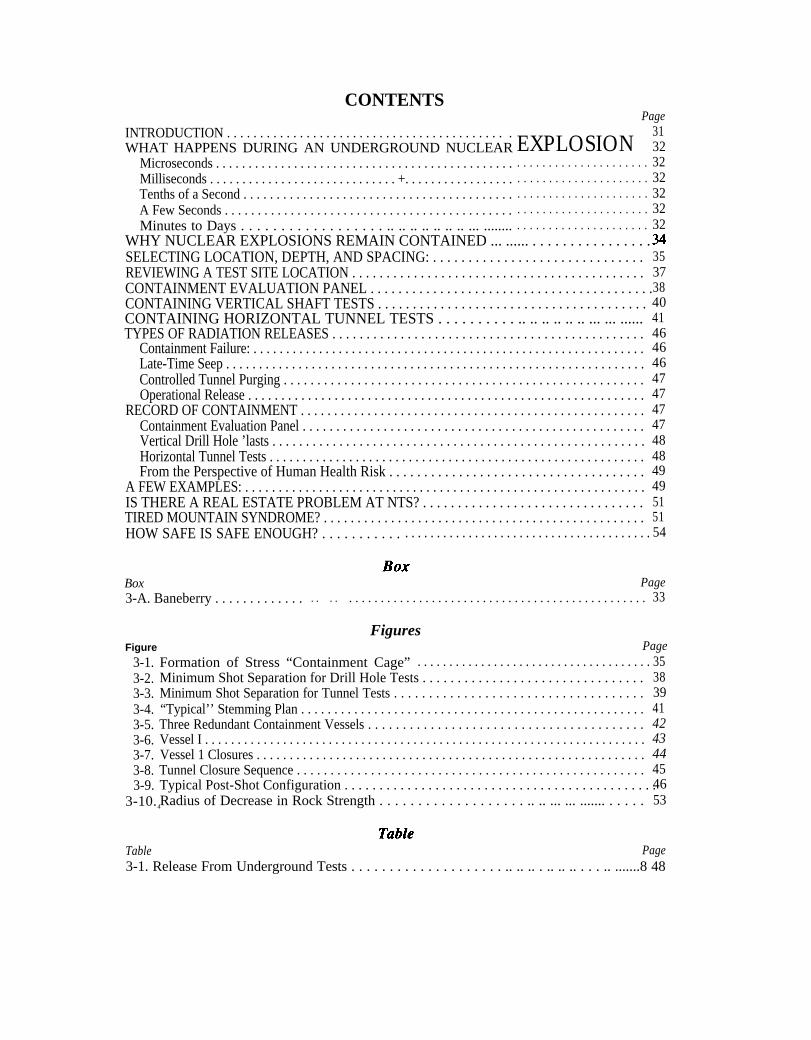
At first, the explosion creates a pressurized cavityfilled with gas that is mostly steam. As the cavitypushes outward, the surrounding rock is compressed(figure 3-l(a)). Because there is essentially a fixedquantity of gas within the cavity, the pressuredecreases as the cavity expands. Eventually thepressure drops below the level required to deformthe surrounding material (figure 3-l(b)). Mean-while, the shock wave has imparted outward motionto the material around the cavity. Once the shockwave has passed, however, the material tries to
return (rebound) to its original position (figure3-l(c)). The rebound creates a large compressivestress field, called a stress “containment cage’around the cavity (figure 3-1 (d)). The physics of thestress containment cage is somewhat analogous tohow stone archways support themselves. In the caseof a stone archway, the weight of each stone pushesagainst the others and supports the archway. In thecase of an underground explosion, the reboundedrock locks around the cavity forming a stress fieldthat is stronger than the pressure inside the cavity.The stress “containment cage” closes any fracturesthat may have begun and prevents new fracturesfrom forming.
The predominantly steam-filled cavity eventuallycollapses forming a chimney. When collapse occurs,the steam in the cavity is condensed through contactwith the cold rock falling into the cavity. Thenoncondensible gases remain within the lowerchimney at low pressure. Once collapse occurs,high-pressure steam is no longer present to drivegases from the cavity region to the surface.
If the testis conducted in porous material, such asalluvium or tuff, the porosity of the medium willprovide volume to absorb gases produced by theexplosion. For example, all of the steam generatedby a 150 kiloton explosion beneath the water tablecan be contained in a condensed state within thevolume of pore space that exists in a hemisphericalpile of alluvium 200 to 300 feet high. Although moststeam condenses before leaving the cavity region,the porosity helps to contain noncondensible gasessuch as carbon dioxide (CO2) and hydrogen (H2).The gas diffuses into the interconnected pore spaceand the pressure is reduced to a level that is too lowto drive the fractures. The deep water table and highporosity of rocks at the Nevada Test Site facilitatecontainment.
Containment also occurs because of the pressureof overlying rock. The depth of burial provides astress that limits fracture growth. For example, as afracture initiated from the cavity grows, gas seepsfrom the fracture into the surrounding material.Eventually, the pressure within the fracture de-creases below what is needed to extend the fracture.At this point, growth of the fracture stops and the gassimply leaks into the surrounding material.
Rock strength is also an important aspect ofcontainment, but only in the sense that an extremelyweak rock (such as water-saturated clay) cannot
Chapter 3-Containing Underground Nuclear Explosions ● 35
A
1 ) Cavity expands outward and deforms surrounding rock. 2) Natural resistance to deformation stops expansion. 3) Cavity contracts(rebounds) from elastic unloading of distant rock. 4) Rebound locks in compressive residual stress around cavity.
SOURCE: Modified from Lawrenee Lwermore National Laboratory.
support a stress containment cage. Detonation withinweak, saturated clay is thought to have been a factorin the release of the Baneberry test. As a result, sitescontaining large amounts of water-saturated clay arenow avoided.
The final aspect of containment is the stemmingthat is put in a vertical hole after the nuclear devicehas been emplaced. Stemming is designed to preventgas from traveling up the emplacement hole. Imper-meable plugs, located at various distances along thestemming column, force the gases into the surround-ing rock where it is ‘‘sponged up’ in the pore spaces.
How the various containment features performdepends on many variables: the size of the explo-sion, the depth of burial, the water content of therock, the geologic structure, etc. Problems mayoccur when the containment cage does not formcompletely and gas from the cavity flows eitherthrough the emplacement hole or the overburdenmaterial. 8 When the cavity collapses, the steamcondenses and only noncondensible gases such ascarbon dioxide (CO2) and hydrogen (H2) remain inthe cavity.9 The CO2 and H2 remain in the chimneyif there is available pore space. If the quantity ofnoncondensible gases is large, however, they can actas a driving force to transport radioactivity through
the chimney or the overlying rock. Consequently,the amount of carbonate material and water in therock near the explosion and the amount of ironavailable for reaction are considered when evaluat-ing containment.10
SELECTING LOCATION, DEPTH,AND SPACING
The site for conducting a nuclear test is, at first,selected only on a tentative basis. The final decisionis made after various site characteristics have beenreviewed. The location, depth of burial, and spacingare based on the maximum expected yield for thenuclear device, the required geometry of the test, andthe practical considerations of scheduling, conven-ience, and available holes. If none of the inventoryholes are suitable, a site is selected and a holedrilled. 11
The first scale for determining how deep anexplosion should be buried was derived from theRainier test in 1957. The depth. based on the cuberoot of the yield, was originally:
Depth = 300 (yield)1/3
where depth was measured in feet and yield in
ELWk of a ,qfess ‘‘containment cage’ may not be a serious problem if the medium is sufticently porous or if the depth of burial is suflicent.
‘Whe C02 is formed from the vaporization of carbonate material; while the Hz is formed when water reacts with the iron in the nuclear device anddiagnostics equipment.
l% ~M~nate mate-id ~ F~enChm~ Flat created co2 hat 15 thought to have caused a ~ep during the DiagOn~ Line test (Nov. 24, 19’7 1 ). Diagonal
Line was the last test on Frenchman Flat; the area is currently considered impractical for underground testing largely because of the carbonate matcnal.IISW. ch. 2, ‘ ‘The Nevada Tkst Site,” for a description of the areas each Laboratory uses for testing.

36 ● The Containment of Underground Nuclear Explosions
Photo credit: Department of Energy
Blanca containment failure, 1958.
kilotons. The first few tests after Rainier, however, thus became: 300 (yield)’/’ “plus-a-few-hundred-were detonated at greater depths than this formula f e e t .requires because it was more convenient to minetunnels deeper in the Mesa. It was not until‘‘ Blanca,’ October 30, 1958, that a test wasconducted exactly at 300 (yield) l/3 feet to test thedepth scale. The containment of the Blanca explo-sion, however, was unsuccessful and resulted in asurface venting of radioactive material. As a conse-quence, the depth scale was modified to include theaddition of a few hundred feet as a safety factor and
Today, the general depth of burial can be approxi-mated by the equation:
Depth = 400 (yield)’ /q,
where depth is measured in feet and yield inkilotons. 12 The minimum depth of burial, however,is 600 feet. 13 Consequently, depths of burial varyfrom 600 feet for a low-yield device, to about 2,100feet for a large-yield test. The depth is scaled to the
IZ’ ‘~b]ic Safety for Nuclear Weapons TCSIS, ” Unlmd States Environmental Protection Agency, January, 1984.!sThe &)().fW[ dcp~ ~= chosen as a minimum after a stalisti~al study show~ that ~C likelihood of a seep of radioactive makrid K) the surface for
explosions buried 600 feet or more was about 1/2 as great as for explosions at less than 500 feet, even if they were buried at the same scale-depth ineaeh case.
Chapter Containing Underground Nuclear Explosions ● 37
‘‘maximum credible yield’ that the nuclear deviceis thought physically capable of producing, not tothe design yield or most likely yield. 14
Whether a test will be conducted on Pahute Mesaor Yucca Flat depends on the maximum credibleyield. Yucca Flat is closer to support facilities andtherefore more convenient, while the deep watertable at Pahute Mesa is more economical for largeyield tests that need deep, large diameter emplace-ment holes. Large yield tests in small diameter holes(less than 7 feet) can be conducted in Yucca Flat. Atest area may also be chosen to avoid schedulingconflicts that might result in a test damaging the holeor diagnostic equipment of another nearby test. Oncethe area has been chosen, several candidate sites areselected based on such features as: proximity toprevious tests or existing drill holes; geologicfeatures such as faults, depth to basement rock, andthe presence of clays or carbonate materials; andpractical considerations such as proximity to powerlines, roads, etc.
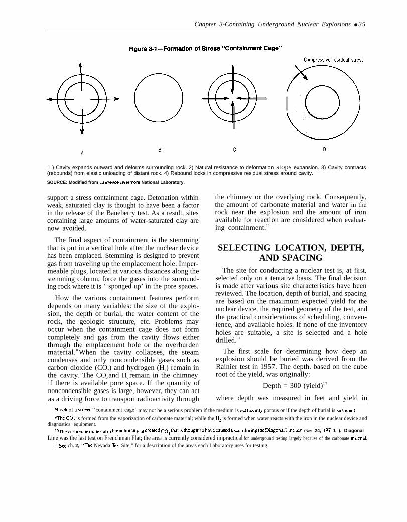
In areas well suited for testing, an additional siteselection restriction is the proximity to previoustests. For vertical drill hole tests, the minimum shotseparation distance is about one-half the depth ofburial for the new shot (figure 3-2). For shallowshots, this separation distance allows tests to bespaced so close together that in some cases, thesurface collapse craters coalesce. The 1/2 depth ofburial distance is a convention of convenience,rather than a criterion for containment.15 It is, forexample, difficult to safely place a drilling rig tooclose to an existing collapse crater.
Horizontal tunnel tests are generally spaced witha minimum shot separation distance of twice thecombined cavity radius plus 100 feet, measuredfrom the point of detonation (called the “workingpoint”) (figure 3-3). In other words, two tests with100 foot radius cavities would be separated by 300feet between cavities, or 500 feet (center to center).The size of a cavity formed by an explosion isproportional to the cube root of the yield and can beestimated by:
Radius = 55 (yield) ’h,
where the radius is measured in feet and the yield in
kilotons. For example, an 8 kiloton explosion wouldbe expected to produce an underground cavity withapproximately a 110 foot radius. Two such testexplosions would require a minimum separationdistance of 320 feet between cavities or 540 feetbetween working points.
Occasionally, a hole or tunnel is found to beunsuitable for the proposed test. Such a situation,however, is rare, occurring at a rate of about 1 out of25 for a drill hole test and about 1 out of 15 for atunnel test. 16 Usually, a particular hole that is foundunacceptable for one test can be used for another testat a lower yield.
REVIEWING A TEST SITELOCATION
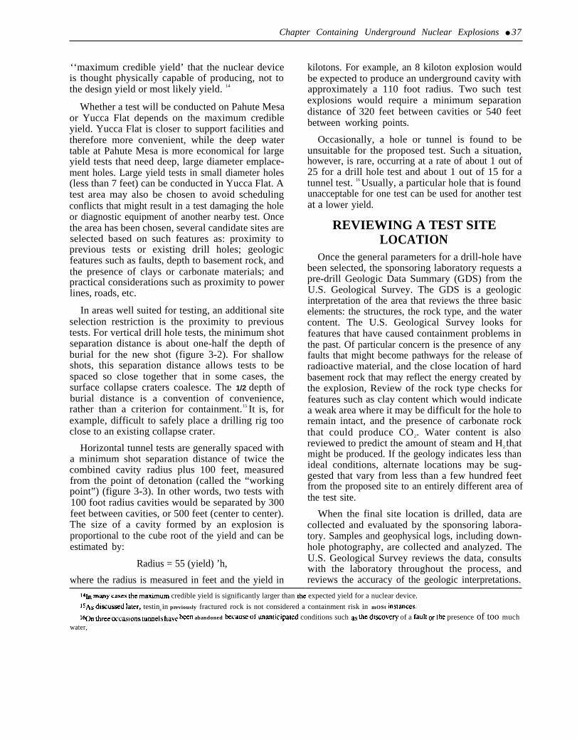
Once the general parameters for a drill-hole havebeen selected, the sponsoring laboratory requests apre-drill Geologic Data Summary (GDS) from theU.S. Geological Survey. The GDS is a geologicinterpretation of the area that reviews the three basicelements: the structures, the rock type, and the watercontent. The U.S. Geological Survey looks forfeatures that have caused containment problems inthe past. Of particular concern is the presence of anyfaults that might become pathways for the release ofradioactive material, and the close location of hardbasement rock that may reflect the energy created bythe explosion, Review of the rock type checks forfeatures such as clay content which would indicatea weak area where it may be difficult for the hole toremain intact, and the presence of carbonate rockthat could produce CO2. Water content is alsoreviewed to predict the amount of steam and H2 thatmight be produced. If the geology indicates less thanideal conditions, alternate locations may be sug-gested that vary from less than a few hundred feetfrom the proposed site to an entirely different area ofthe test site.
When the final site location is drilled, data arecollected and evaluated by the sponsoring labora-tory. Samples and geophysical logs, including down-hole photography, are collected and analyzed. TheU.S. Geological Survey reviews the data, consultswith the laboratory throughout the process, andreviews the accuracy of the geologic interpretations.
IQk mmy cwws tie muimum credible yield is significantly larger than the expected yield for a nuclear device.
ISA.S di=uw~ ]aler, testing in previously fractured rock is not considered a containment risk in mOSt iM3WX.
1- ~rw ~culon5 tuMe]5 have &n abandoned ~auw of un~[icipa[ed conditions such ~$ tie di~overy of a fau]t or the presence of too muchwater,

38 ● The Containment of Underground Nuclear Explosions
Figure 3-2-Minimum Shot Separation for Drill Hole Tests
Yucca flats
Diagram to approximate scale
Scale illustration of the minimum separation distance (1/2 depth of burial) for vertical drill hole tests. Thedepth of burial is based on the maximum credible yield.
SOURCE: Office of Technology Assessment, 1989
To confirm the accuracy of the geologic descriptionand review and evaluate containment considera-tions, the Survey also attends the host laboratory’ssite proposal presentation to the Containment Evalu-ation Panel.
CONTAINMENT EVALUATIONPANEL
One consequence of the Baneberry review was therestructuring of what was then called the TestEvaluation Panel. The panel was reorganized andnew members with a wider range of geologic andhydrologic expertise were added. The new panel wasnamed the Containment Evaluation Panel (CEP);and their first meeting was held in March, 1971.
The Containment Evaluation Panel presentlyconsists of a Chairman and up to 11 panel members.
Six of the panel members are representatives fromLawrence Livermore National Laboratory, Los AlamosNational Laboratory, Defense Nuclear Agency, San-dia National Laboratory, U.S. Geological Survey,and the Desert Research Institute. An additional 3 to5 members are also included for their expertise indisciplines related to containment. The chairman ofthe panel is appointed by the Manager of NevadaOperations (Department of Energy), and panelmembers are nominated by the member institutionwith the concurrence of the chairman and approvalof the Manager. The panel reports to the Manager ofNevada Operations.
Practices of the Containment Evaluation Panelhave evolved throughout the past 18 years; however,their purpose, as described by the Containment

Chapter Containing Underground Nuclear Explosions ● 39
Figure 3-3--Minimum Shot Separation for Tunnel Tests
Rainier Mesa
Tunnel tests are typicallyoverburied. Collapse chimneysdo not usually extend to surface.
I
Diagram to approximate scale
Scale illustration of the minimum separation distance (2 combined cavity radii plus 100 feet) forhorizontal tunnel tests. Tunnel tests are typically overburied. Collapse chimneys do not usually extendto the surface.
SOURCE: Office of Technology Assessment, 1989
Evaluation Charter, remains specifically defined as 4. maintain a historical record of each evaluationfollows:17 and of the data, proceedings, and discussions
pertaining thereto.
1.
2.
3.
evaluate, as an independent organization re-porting to the Manager of Nevada Operations,the containment design of each proposednuclear test;
assure that all relevant data available forproper evaluation are considered;
advise the manager of Nevada Operations ofthe technical adequacy of such design from theviewpoint of containment, thus providing themanager a basis on which to request detona-tion authority; and
Although the CEP is charged with rendering ajudgment as to the adequacy of the design of thecontainment, the panel does not vote. Each memberprovides his independent judgment as to the pros-pect of containment, usually addressing his own areaof expertise but free to comment on any aspect of thetest. The Chairman is in charge of summarizingthese statements in a recommendation to the man-ager on whether to proceed with the test, based onlyon the containment aspects. Containment Evalua-tion Panel guidelines instruct members to make theirjudgments in such a way that:
17 Cont~ent Ev~u~ti~n ~~er, June 1, 1986, s~ti~n II.

—
40 ● The Containment of Underground Nuclear Explosions
Considerations of cost, schedules, and test objectivesshall not enter into the review of the technicaladequacy of any test from the viewpoint of contain-ment. 18
Along with their judgments on containment, eachpanel member evaluates the probability of contain-ment using the following four categories: 19
1.
2.
3.
4.
Category A: Considering all containment fea-tures and appropriate historical, empirical, andanalytical data, the best judgment of themember indicates a high confidence in suc-cessful containment as defined in VIII.F.below.Category B: Considering all containment fea-tures and appropriate historical, empirical, andanalytical data, the best judgment of themember indicates a less, but still adequate,degree of confidence in successful contain-ment as defined in VIII.F. below.Category C’: Considering all containment fea-tures and appropriate historical, empirical, andanalytical data, the best judgment of themember indicates some doubt that successfulcontainment, as described in VIII.F. below,will be achieved.Unable to Categorize
Successful containment is defined for the CEP as:
. . . no radioactivity detectable off-site as measuredby normal monitoring equipment and no unantici-pated release of activity on-site.
The Containment Evaluation Panel does not havethe direct authority to prevent a test from beingconducted. Their judgment, both as individuals andas summarized by the Chairman, is presented to theManager. The Manager makes the decision as towhether a Detonation Authority Request will bemade. The statements and categorization from eachCEP member are included as part of the permanentDetonation Authority Request.
Although the panel only advises the Manager, itwould be unlikely for the Manager to request
detonation if the request included a judgment by theCEP that the explosion might not be contained. Therecord indicates the influence of the CEP. Sinceformation of the panel in 1970, there has never beena Detonation Authority Request submitted for ap-proval with a containment plan that received a “C”(“some doubt”) categorization from even onemember. 20 21
The Containment Evaluation Panel serves anadditional role in improving containment as aconsequence of their meetings. The discussions ofthe CEP provide an ongoing forum for technicaldiscussions of containment concepts and practices.As a consequence, general improvements to contain-ment design have evolved through the panel discus-sions and debate.
CONTAINING VERTICALSHAFT TESTS
Once a hole has been selected and reviewed, astemming plan is made for the individual hole. Thestemming plan is usually formulated by adaptingpreviously successful stemming plans to the particu-larities of a given hole. The objective of the plan isto prevent the emplacement hole from being the pathof least resistance for the flow of radioactivematerial. In doing so, the stemming plan must takeinto account the possibility of only a partial collapse:if the chimney collapse extends only halfway to thesurface, the stemming above the collapse mustremain intact.
Lowering the nuclear device with the diagnosticsdown the emplacement hole can take up to 5 days.A typical test will have between 50 and 250diagnostic cables with diameters as great as 15/~inches packaged in bundles through the stemmingcolumn. After the nuclear device is lowered into theemplacement hole, the stemming is installed. Figure3-4 shows a typical stemming plan for a Lawrence
18conta~ment Ev~~ion Pi ne ] ch~r, June 1, 1986, Swtion 111-D.
lgcont~ent Ev~uation Panel Chaner, June 1, 1986, Section WI.
me grading system for containment plans has evolved since the early 1970’s. Prior to April, 1977, the Containment Evacuation Panel categorizedtests using the Roman numerals (I-IV) where 1-111 had about the same meaning as A-C and IV was a D which eventually was dropped as a letter andjust became ‘‘unable to categorize. ”
21 However, one shot (Mmdo) was submitted with an “unable to categorize” categorization, Mundo was a joint US-UK test conducted on May 1,1984.

Chapter 3--Containing Underground Nuclear Explosions ● 41
Figure 3-4--"Typical” Stemming Plan
Plug
Typical stemming sequence of coarse material, fine material, andsanded gypsum plug used by Lawrence Livermore NationalLaboratory for vertical drill hole tests.
SOURCE: Modified from Lawrence Livermore National Laboratory.
Livermore test with six sanded gypsum concreteplugs.22 The plugs have two purposes: 1) to impedegas flow, and 2) to serve as structural platforms thatprevent the stemming from falling out if only apartial collapse occurs. Under each plug is a layer ofsand-size fine material. The sand provides a base forthe plug. Alternating between the plugs and thefines, coarse gravel is used to fill in the rest of thestemming. The typical repeating pattern used forstemming by Los Alamos, for example, is 50 feet ofgravel, 10 feet of sand, and a plug.
All the diagnostic cables from the nuclear deviceare blocked to prevent gas from finding a pathwaythrough the cables and traveling to the surface. Cablefan-out zones physically separate the cables at plugs
so that the grout and fines can seal between them.Frequently, radiation detectors are installed betweenplugs to monitor the post-shot flow of radiationthrough the stemming column.
CONTAINING HORIZONTALTUNNEL TESTS
The containment of a horizontal tunnel test isdifferent from the containment of a vertical drill holetest because the experimental apparatus is intendedto be recovered. In most tests, the objective is toallow direct radiation from a nuclear explosion toreach the experiment, but prevent the explosivedebris and fission products from destroying it.Therefore, the containment is designed for twotasks: 1 ) to prevent the uncontrolled release ofradioactive material into the atmosphere for publicsafety, and 2) to prevent explosive debris fromreaching the experimental test chamber.
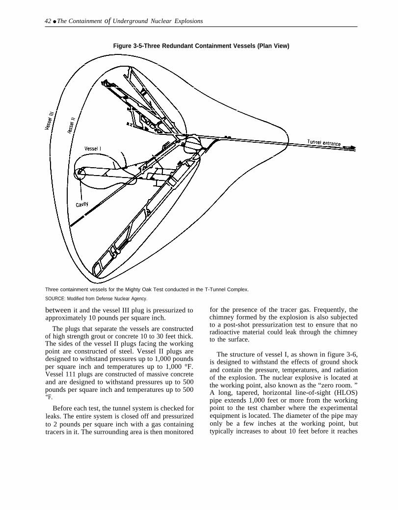
Both types of horizontal tunnel tests (effects testsand cavity tests) use the same containment conceptof three redundant containment ‘‘vessels’ that nestinside each other and are separated by plugs (figure3-5).23 Each vessel is designed to independentlycontain the nuclear explosion, even if the othervessels fail. If, for example, gas leaks from vessel Iinto vessel II, vessel II has a volume large enough sothat the resulting gas temperatures and pressureswould be well within the limits that the plugs aredesigned to withstand. The vessels are organized asfollows:
Vessel I is designed to protect the experiment bypreventing damage to the equipment and allowing itto be recovered.
Vessel II is designed to protect the tunnel systemso that it can be reused even if vessel I fails and theexperimental equipment is lost.
Vessel III is designed purely for containment,such that even if the experimental equipment is lostand the tunnel system contaminated, radioactivematerial will not escape to the atmosphere.
In addition to the three containment vessels, thereis a gas seal door at the entrance of the tunnel systemthat serves as an additional safety measure. The gasseal door is closed prior to detonation and the area
&!A]though L;ve~Ore ~d ~~ ~amos ~~ [he WC gencr~ stemming philosophy, [here Me some differences: For example, Liver-more U.WS sandd
gypsum concrete plugs while Ims Alamos uses plugs made of epoxy. Also, Livermore uses an emplacement pipe for lowering the device downhole, whileLos Alarms lowers the device and diagnostic carmister on a wire rope harness.
ZSSW ch. 2 for a dixussion of types of nuc]ew tests.
42 ● The Containment of Underground Nuclear Explosions
Figure 3-5-Three Redundant Containment Vessels (Plan View)
Three containment vessels for the Mighty Oak Test conducted in the T-Tunnel Complex.
SOURCE: Modified from Defense Nuclear Agency.
between it and the vessel III plug is pressurized toapproximately 10 pounds per square inch.
The plugs that separate the vessels are constructedof high strength grout or concrete 10 to 30 feet thick.The sides of the vessel II plugs facing the workingpoint are constructed of steel. Vessel II plugs aredesigned to withstand pressures up to 1,000 poundsper square inch and temperatures up to 1,000 °F.Vessel 111 plugs are constructed of massive concreteand are designed to withstand pressures up to 500pounds per square inch and temperatures up to 500“F.
Before each test, the tunnel system is checked forleaks. The entire system is closed off and pressurizedto 2 pounds per square inch with a gas containingtracers in it. The surrounding area is then monitored
for the presence of the tracer gas. Frequently, thechimney formed by the explosion is also subjectedto a post-shot pressurization test to ensure that noradioactive material could leak through the chimneyto the surface.
The structure of vessel I, as shown in figure 3-6,is designed to withstand the effects of ground shockand contain the pressure, temperatures, and radiationof the explosion. The nuclear explosive is located atthe working point, also known as the “zero room. ”A long, tapered, horizontal line-of-sight (HLOS)pipe extends 1,000 feet or more from the workingpoint to the test chamber where the experimentalequipment is located. The diameter of the pipe mayonly be a few inches at the working point, buttypically increases to about 10 feet before it reaches

Chapter 3-Containing Underground Nuclear Explosions ● 43
Figure 3-6--Vessel I
Key: GSAC = gas seal auxiliary closure; MAC = modified auxiliaryclosure; TAPS = Tunnel and pipe seal
The HLOS Vessel I is designed to protect the experimentalequipment after allowing radiation to travel down the pipe.
SOURCE: Modified from Defense Nuclear Agency.
the test chamber.24 The entire pipe is vacuumpumped to simulate the conditions of space and tominimize the attenuation of radiation. The bypassdrift (an access tunnel), located next to the line ofsight pipe, is created to provide access to the closuresand to different parts of the tunnel system. Thesedrifts allow for the nuclear device to be placed in thezero room and for late-time emplacement of testequipment. After the device has been emplaced atthe working point, the bypass drift is completelyfilled with grout. After the experiment, parts of thebypass drift will be reexcavated to permit access tothe tunnel system to recover the pipe and experimen-tal equipment.
The area around the HLOS pipe is also filled withgrout, leaving only the HLOS pipe as a clearpathway between the explosion and the test cham-ber. Near the explosion, grout with properties similarto the surrounding rock is used so as not to interferewith the formation of the stress containment cage.Near the end of the pipe strong grout or concrete isused to support the pipe and closures. In between,the stemming is filled with super-lean grout de-signed to flow under moderate stress. The super-leangrout is designed to fill in and effectively plug anyfractures that may form as the ground shockcollapses the pipe and creates a stemming plug.
As illustrated in figure 3-6, the principal compo-nents of an HLOS pipe system include a working
point room, a muffler, a modified auxiliary closure(MAC), a gas seal auxiliary closure (GSAC), and atunnel and pipe seal (TAPS). All these closures areinstalled primarily to protect the experimental equip-ment. The closures are designed to shut off the pipeafter the radiation created by the explosion hastraveled down to the test chamber, but beforematerial from the blast can fly down the pipe anddestroy the equipment.
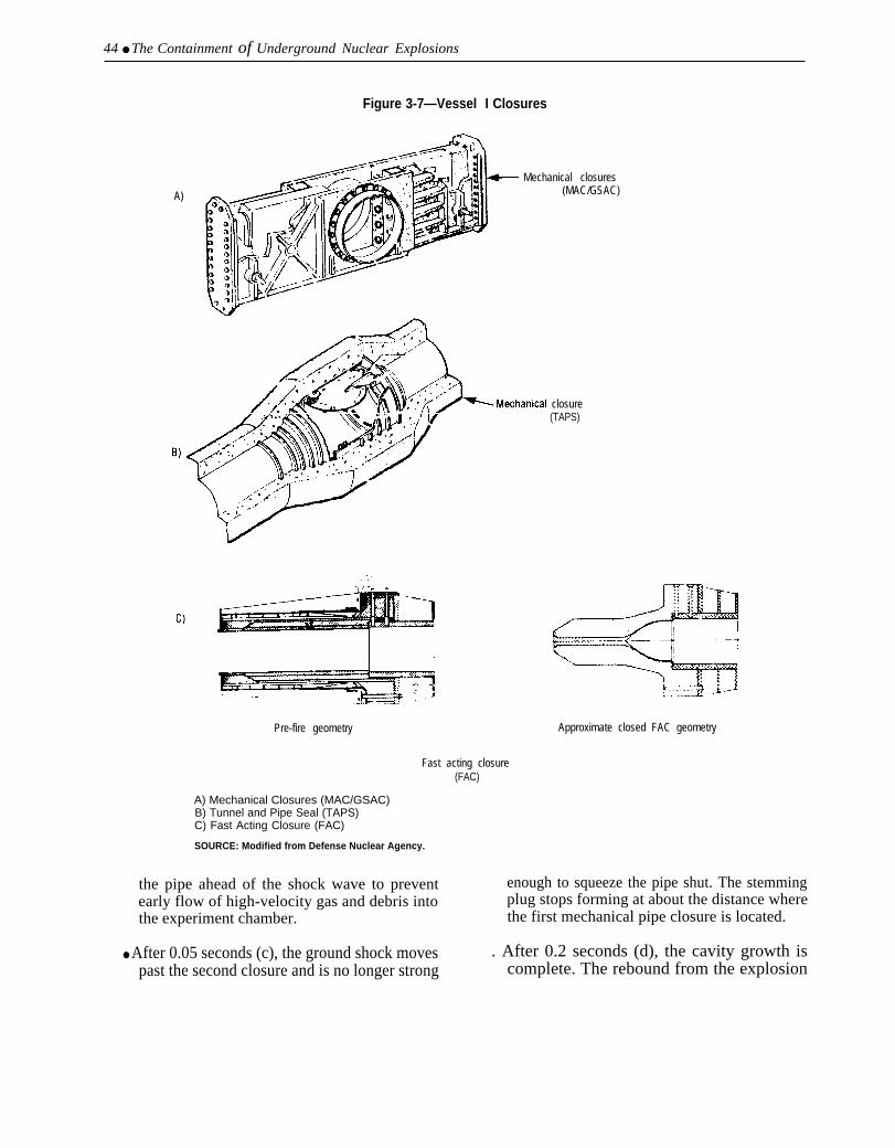
The working point room is a box designed tohouse the nuclear device. The muffler is an ex-panded region of the HLOS pipe that is designed toreduce flow down the pipe by allowing expansionand creating turbulence and stagnation. The MAC(figure 3-7(a)) is a heavy steel housing that containstwo 12-inch-thick forged-aluminum doors designedto close openings up to 84 inches in diameter. Thedoors are installed opposite each other, perpendicu-lar to the pipe. The doors are shut by high pressuregas that is triggered at the time of detonation.Although the doors close completely within 0.03seconds (overlapping so that each door fills thetunnel), in half that time they have met in the middleand obscure the pipe. The GSAC is similar to theMAC except that it is designed to provide a gas-tightclosure. The TAPS closure weighs 40 tons and thedesign (figure 3-7(b)) resembles a large toilet seat,The door, which weighs up to 9 tons, is hinged on thetop edge and held in the horizontal (open) position.When the door is released, it swings down by gravityand slams shut in about 0.75 seconds. Any pressureremaining in the pipe pushes on the door making theseal tighter. The MAC and GSAC will withstandpressures up to 10,000 pounds per square inch. TheTAPS is designed to withstand pressures up to 1,000pounds per square inch, and temperatures up to1,000 ‘F.
When the explosion is detonated radiation travelsdown the HLOS pipe at the speed of light, Thecontainment process (figure 3-8 (a-e), triggered at thetime of detonation, occurs in the following sequenceto protect experimental equipment and containradioactive material produced by the explosion:
. After 0.03 seconds (b), the cavity created by theexplosion expands and the shock wave movesaway from the working point and approachesthe MAC. The shock wave collapses the pipe,squeezing it shut, and forms a stemming“plug.’ Both the MAC and the GSAC shut off
zq~ ~cmlon, the di~cter of the pipe has inm-ca..ed 1020 feet.
44 ● The Containment of Underground Nuclear Explosions
Figure 3-7—Vessel I Closures
A)
Mechanical closures(MAC/GSAC)
Pre-fire geometry
closure(TAPS)
Approximate closed FAC geometry
Fast acting closure(FAC)
A) Mechanical Closures (MAC/GSAC)B) Tunnel and Pipe Seal (TAPS)C) Fast Acting Closure (FAC)
SOURCE: Modified from Defense Nuclear Agency.
the pipe ahead of the shock wave to prevent enough to squeeze the pipe shut. The stemmingearly flow of high-velocity gas and debris into plug stops forming at about the distance wherethe experiment chamber. the first mechanical pipe closure is located.
● After 0.05 seconds (c), the ground shock moves . After 0.2 seconds (d), the cavity growth ispast the second closure and is no longer strong complete. The rebound from the explosion
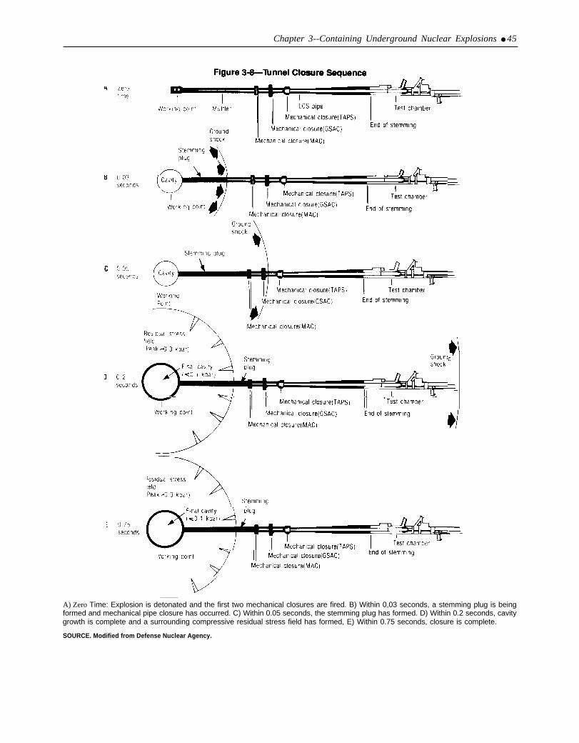
Chapter 3--Containing Underground Nuclear Explosions ● 45
A) Zero Time: Explosion is detonated and the first two mechanical closures are fired. B) Within 0,03 seconds, a stemming plug is beingformed and mechanical pipe closure has occurred. C) Within 0.05 seconds, the stemming plug has formed. D) Within 0.2 seconds, cavitygrowth is complete and a surrounding compressive residual stress field has formed, E) Within 0.75 seconds, closure is complete.
SOURCE. Modified from Defense Nuclear Agency.

46 ● The Containment of Underground Nuclear Explosions
locks in the residual stress field, therebyforming a containment cage. The shock wavepasses the test chamber.
. After 0.75 seconds (e), the final mechanical seal(TAPS) closes, preventing late-time explosiveand radioactive gases from entering the testchamber.
The entire closure process for containment takesless than 3/4 of a second. Because the tests aretypically buried at a depth greater than necessary forcontainment, the chimney does not reach the surfaceand a collapse crater normally does not form. Atypical post-shot chimney configuration with itsapproximate boundaries is shown in figure 3-9.
In lower yield tests, such as those conducted in theP-tunnel complex, the first mechanical closure is aFast Acting Closure (FAC) rather than a MAC.25
The FAC (figure 3-7(c)) closes in 0.001 seconds andcan withstand pressures of 30,000 pounds per squareinch. The FAC acts like a cork, blocking off theHLOS pipe early, and preventing debris and stem-ming material from flying down the pipe. A similarclosure is currently being developed for larger yieldtunnel tests.
TYPES OF RADIATION RELEASESTerms describing the release or containment of
underground nuclear explosions have been refinedto account for the volume of the material and theconditions of the release. The commonly used termsare described below.
Containment Failure
Containment failures are releases of radioactivematerial that do not fall within the strict definition ofsuccessful containment, which is described by theDepartment of Energy as:
Containment such that a test results in no radioac-tivity detectable off site as measured by normalmonitoring equipment and no unanticipated releaseof radioactivity onsite. Detection of noble gases thatappear onsite long after an event, due to changingatmospheric conditions, is not unanticipated. Antici-pated releases will be designed to conform tospecific guidance from DOE/HQ.26
Containment failures are commonly described as:
Approximatechimneyboundary
n
. . . . . . . .. . . . . . . . . .. . . . . . . . . .. . . . . . . . . .. . . . . . . . . .. . . . . . . . . .. . . . . . . . . .. . .
Tunnel shots are typically overburied and the collapse chimneyrarely extends to the surface.
SOURCE: Modified from Defense Nuclear Agency.
Ventings
Ventings are prompt, massive, uncontrolled re-leases of radioactive material. They are character-ized as active releases under pressure, such as whenradioactive material is driven out of the ground bysteam or gas. ‘‘ Baneberry,’ in 1970, is the lastexample of an explosion that ‘‘vented. ”
Seeps
Seeps, which are not visible, can only be detectedby measuring for radiation. Seeps are characterizedas uncontrolled slow releases of radioactive materialwith little or no energy.
Late-Time Seep
Late-time seeps are small releases of nonconden-sable gases that usually occur days or weeks after avertical drill hole test. The noncondensable gasesdiffuse up through the pore spaces of the overlyingrock and are thought to be drawn to the surface by adecrease in atmospheric pressure (called “atmos-pheric pumping”).
25~ p-t~e] complex is rnlned in Aqueduct Mesa ~d h~ ]ess overb~den (h~ the Nw.nnel complex in Rainier Mesa. Therefore, p-tUfIne] is
generally used for lower yield tests.~Satlon VIII.F, Containrnen[ Evaluation Panel Charter.
Chapter 3--Containing Underground Nuclear Explosions ● 47
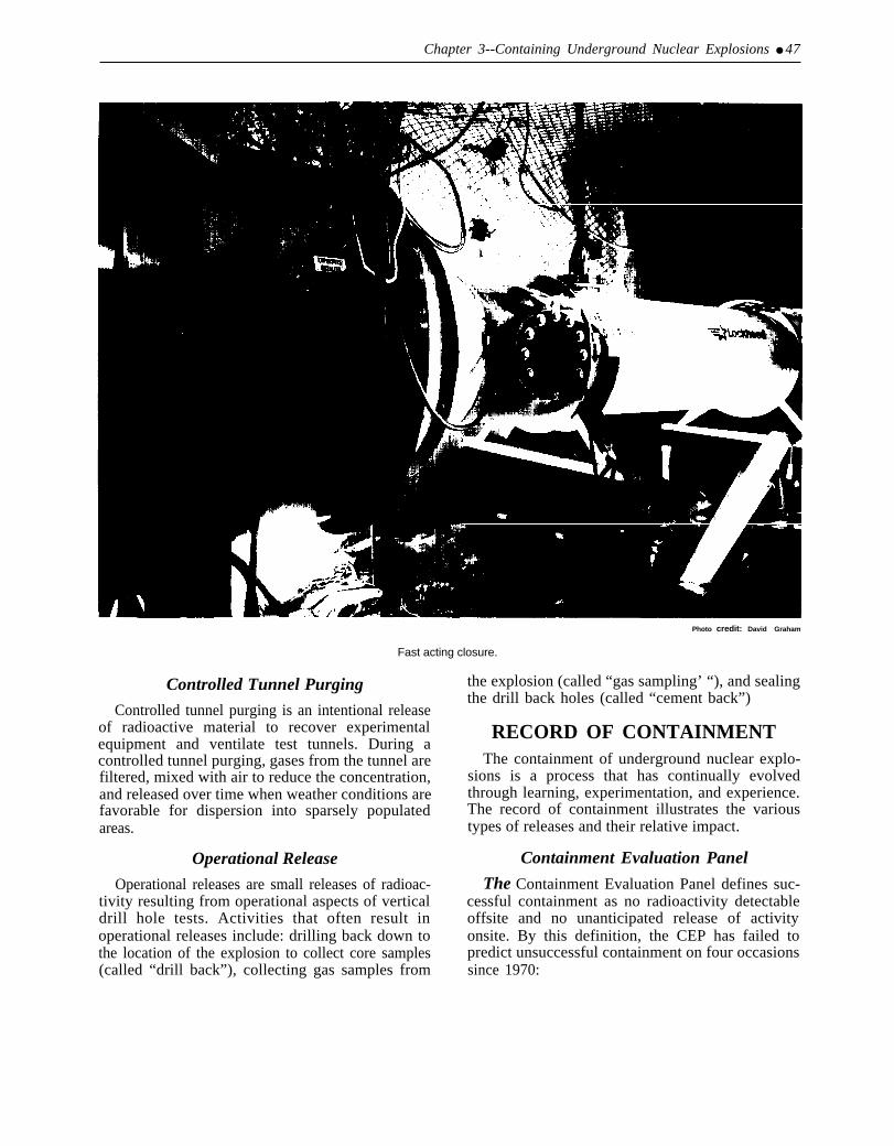
Photo credit: David Graham
Fast acting closure.
Controlled Tunnel Purging
Controlled tunnel purging is an intentional releaseof radioactive material to recover experimentalequipment and ventilate test tunnels. During acontrolled tunnel purging, gases from the tunnel arefiltered, mixed with air to reduce the concentration,and released over time when weather conditions arefavorable for dispersion into sparsely populatedareas.
Operational Release
Operational releases are small releases of radioac-tivity resulting from operational aspects of verticaldrill hole tests. Activities that often result inoperational releases include: drilling back down tothe location of the explosion to collect core samples(called “drill back”), collecting gas samples from
the explosion (called “gas sampling’ “), and sealingthe drill back holes (called “cement back”)
RECORD OF CONTAINMENTThe containment of underground nuclear explo-
sions is a process that has continually evolvedthrough learning, experimentation, and experience.The record of containment illustrates the varioustypes of releases and their relative impact.
Containment Evaluation Panel
The Containment Evaluation Panel defines suc-cessful containment as no radioactivity detectableoffsite and no unanticipated release of activityonsite. By this definition, the CEP has failed topredict unsuccessful containment on four occasionssince 1970:

48 ● The Containment of Underground Nuclear Explosions
Camphor:
Diagonal Line:
Riola:
Agrini:
June 29, 1971, horizontal tunnel test,less than 20 kilotons, radioactivity de-tected only on-site.November 24, 1971, vertical shaft test,less than 20 kilotons, radioactivity de-tected off-site.September 25, 1980, vertical shaft test,less than 20 kilotons, radioactivity de-tected off-site.March 31, 1984, vertical shaft test, lessthan 20 kilotons, radioactivity detectedonly on-site.
These are the only tests (out of more than 200)where radioactive material has been unintentionallyreleased to the atmosphere due to containmentfailure. In only two of the cases was the radioactivitydetected outside the geographic boundary of theNevada Test Site.
There have, however, been several other instanceswhere conditions developed that were not expected.For example, during the Midas Myth test onFebruary 15, 1984, an unexpected collapse crateroccurred above the test tunnel causing injuries topersonnel. In addition, the tunnel partially collapsed,damaging experimental equipment. During the MightyOak test on April 10, 1986, radioactive materialpenetrated through two of the three containmentvessels. Experimental equipment worth $32 millionwas destroyed and the tunnel system ventilationrequired a large controlled release of radioactivematerial (table 3-1). In the case of Midas Myth, noradioactive material was released (in fact, all radio-active material was contained within vessel I). In thecase of Mighty Oak, the release of radioactivematerial was intentional and controlled. Conse-quently, neither of these tests are considered con-tainment failures by the CEP.
Vertical Drill Hole Tests
As discussed previously, vertical drill-hole testscommonly use a stemming plan with six sandedgypsum plugs or three epoxy plugs. Approximately50 percent of the vertical drill hole tests show allradiation being contained below the first plug, Insome cases, radiation above the plug may not signifyplug failure, but rather may indicate that radioactivematerial has traveled through the medium around theplug.
Table 3-1--Releases From Underground Wats(normalized to 12 hours after event)
All releases 1971-1988:Containment Failures:
Camphor, 1971 b.. . . . . . . . . . . . . . . . . . . . . . .......360 CiDiagonal Line, 1971 . . . . . . . . . . . . . . . . . . ........6,800Riola, 1980 . . . . . . . . . . . . . . . . . ................3,100Agrini, 1984 . . . . . . . . . . . . . . . . .................. 690
Late-time Seeps:Kappeli, 1984 . . . . . . . . . . . . . . . . .... . . .. .... .....12Tierra, 1984 . . . . . . . . . . . . . . . . . .................600Labquark, 1986 . . . . . . . . . . . . . . . . . . . . . . . . . . . . . . . 20Bodie, 19863 . . . . . . . . . . . . . . . . . . . . . . . . . . .. ......52
Controlled Tunnel Purgings:Hybla Fair, 1974 . . . . . . . . . . . . . . . . . .............500Hybla Gold, 1977 . . . . . . . . . . . . . . . . . ...............0.005Miners Iron, 1980 . . . . . . . . . . . . . . . . . ..............0.3Huron Landing, 1982 . . . . . . . . . . . . . . . . . .........280Mini Jade, 1983 . . . . . . . . . . . . . . . . . . . . . . . . . ........1Mill Yard, 1985 . . . . . . . . . . . . . . . . . ................5.9Diamond Beech,1985 . . . . . . . . . . . . . . . . . . ..........1.1Misty Rain, 1985 . . . . . . . . . . . . . . . . . . . . . . . . .......63Mighty Oak, 1986 . . . . . . . . . . . . . . . . . ..........36,000Mission Ghost, 1987 C . . . . . . . . . . . . . . . . . . . . .. ......3
Operational Releases:108 tests from 1970-1988d . . . . . . . . . . . . . . . . . . . . .. 5,500
Total since Baneberry: 54,000 Ci
Major pre-1971 releases:Platte, 1962, ., . . . . . . . . . . . . . . . . . . . . . .....1,900,000 CiEel, 1962 . . . . . . . . . . . . . . . . . . . . ..........1,900,000Des Moines, 1962 . . . . . . . . . . . . . . . . . .....11,000,000Baneberry, 1970 . . . . . . . . . . . . . . . . . ........6,700,00026 others from 1958-1970 . . . . . . . . . . . . ....3,800,000
Total: 25,300,000 CiOther Releases for Reference
NTS Atmospheric Testing 1951-1963: . .12,000,000,000 Ci1 Kiloton Aboveground Explosion: . ........10,000,000Chernobyl (estimate): . . . . ................81,000,000
aR+12 values apply only to containment failures, others are at time ofrelease.
bThe camphor fatlure includes 140 CI from tunnel PLJr9in9.cBodie and Ms.slon Ghost also had drill-back releases.dMany of these Operational releases are associated with tests that were not
announced.
SOURCE. OffIce of Technology Assessment, 1989.
All three of the vertical drill hole tests thatreleased radioactive material through containmentfailure were low yield tests of less than 20 kilotons.In general, the higher the yield, the less chance thereis that a vertical drill hole test will release radioactiv-ity. 27
Horizontal Tunnel Tests
There have been no uncontrolled releases ofradioactive material detected offsite in the 31 tunneltests conducted since 1970. Furthermore, all but onetest, Mighty Oak, have allowed successful recovery
27H1@r yield te~t~ UC more ]ikc]y t. produ~c a c~n~ainrncnl Cage ~d result in the formation of a Co]lapse crater. AS discussed car]ier in this chapter“why nuclear explosions remain contained, ’ such features contribute to the containment of the explosion.

Chapter 3--Containing Underground Nuclear Explosions ● 49
of the experimental equipment. Mighty Oak andCamphor are the only tests where radioactivityescaped out of vessel II. In no test, other thanCamphor, has radioactive material escaped out ofvessel III. Camphor resulted in an uncontrolledrelease of radioactive material that was detectedonly on site.
There have been several instances when smallamounts of radioactivity were released intentionallyto the atmosphere through controlled purging. Inthese cases, the decision was made to vent the tunneland release the radioactivity so the experimentalresults and equipment could be recovered. Theevents that required such a controlled release are the10 tests where radioactive material escaped out ofvessel I and into vessel II, namely:
Hybla Fair, October 28, 1974.
Hybla Gold, November 1, 1977.
Miners Iron, October 31, 1980.
Huron Landing, September 23, 1982.
Mini Jade, May 26, 1983.
Mill Yard, October 9, 1985.
Diamond Beech, October 9,
Misty Rain, April 6, 1985.
1985.
Mighty Oak, April 10, 1986.
Mission Ghost, June 20, 198728
In most cases, the release was due to the failure ofsome part of the experiment protection system.
Table 3-1 includes every instance (for bothannounced and unannounced tests) where radioac-tive material has reached the atmosphere under anycircumstances whatsoever from 1971 through 1988.The lower part of table 3-1 summarizes undergroundtests prior to 1971 and provides a comparison withother releases of radioactive material.
Since 1970, 126 tests have resulted in radioactivematerial reaching the atmosphere with a total releaseof about 54,000 Curies. Of this amount, 11,500Ci were due to containment failure and late-timeseeps. The remaining 42,500 Ci were operationalreleases and controlled tunnel ventilations—withMighty Oak (36,000 Ci) as the main source. Section
3 of the table shows that the release of radioactivematerial from underground nuclear testing sinceBaneberry (54,000 Ci) is extremely small in compar-ison to the amount of material released by pre-Baneberry underground tests (25,300,000 Ci), theearly atmospheric tests at the Nevada Test Site, oreven the amount that would be released by al-kiloton explosion conducted above ground (l0,000,000Ci).
From the Perspective of Human Health Risk
If a single person had been standing at theboundary of the Nevada Test Site in the area ofmaximum concentration of radioactivity for everytest since Baneberry (1970), that person’s totalexposure would be equivalent to 32 extra minutesof normal background exposure (or the equiva-lent of 1/1000 of a single chest x-ray).
A FEW EXAMPLES:Although over 90 percent of all test explosions
occur as predicted, occasionally something goeswrong. In some cases, the failure results in the lossof experimental equipment or requires the controlledventilation of a tunnel system. In even more rarecases (less than 3 percent), the failure results in theunintentional release of radioactive material to theatmosphere. A look at examples shows situationswhere an unexpected sequence of events contributeto create an unpredicted situation (as occurred inBaneberry (see box 3-l)), and also situations wherethe full reason for containment failure still remainsa mystery.
1. Camphor (June 29, 1971, horizontal tunnel test,less than 20 kilotons, radioactivity detected onlyon-site, )
The ground shock produced by the Camphorexplosion failed to close the HLOS pipe fully. Afterabout 10 seconds, gases leaked through and erodedthe stemming plug. As gases flowed through thestemming plug, pressure increased on the closuredoor behind the experiment. Gases leaked aroundthe cable passage ways and eroded open a hole.Pressure was then placed on the final door, whichheld but leaked slightly. Prior to the test, thecontainment plan for Camphor received six ‘‘I’from the CEP.29
zs~e Mission Ghost rc]e~ was due to a post-shol drill hole.
290p. cit., footnote 20.

50 ● The Containment of Underground Nuclear Explosions
2. Diagonal Line (November 24, 1971, verticalshaft test, less than 20 kilotons, radioactivity de-tected off-site.)
In a sense, the Diagonal Line seep was predictedby the CEP. Prior to the test, Diagonal Line receivedall “A” categorizations, except from one memberwho gave it a‘ ‘B. ’ ’30 It was a conclusion of the panelthat due to the high CO2 content, a late-time (hoursor days after detonation) seepage was a highprobability. They did not believe, however, that thelevel of radiation would be high enough to bedetectable off-site. Permission to detonate wasrequested and granted because the test objectiveswere judged to outweigh the risk. Diagonal Line wasconducted in the northern part of Frenchman Flat. Itis speculated that carbonate material released CO2
gas that forced radioactive material to leak to thesurface. Diagonal Line was the last test detonated onFrenchman Flat.
3. Riola (September 25, 1980, vertical shaft test,less than 20 kilotons, radioactivity detected off-site.)
Ironically, Riola was originally proposed for adifferent location. The Containment EvaluationPanel, however, did not approve the first locationand so the test was moved. At its new location, Riolawas characterized by the CEP prior to the test with8 “A”s. Riola exploded with only a small fractionof the expected yield. A surface collapse occurredand the failure of a containment plug resulted in therelease of radioactive material.
4. Agrini (March 31, 1984, vertical shaft test, lessthan 20 kilotons, radioactivity detected only on-site. )
The Agrini explosion formed a deep subsidencecrater 60 feet west of the emplacement hole. A smallamount of radioactive material was pushed throughthe chimney by noncondensible gas pressure andwas detected onsite. The containment plan forAgrini received seven ‘‘A’ and two ‘B from theCEP prior to the test. The ‘‘B’*s were due to the useof a new stemming plan.
5. Midas Myth (February 15, 1984, horizontaltunnel test, less than 20 kilotons, no release ofradioactive material.)
All of the radioactive material produced by theMidas Myth test was contained within vessel I, withno release of radioactivity to either the atmosphereor the tunnel system. It is therefore not considered acontainment failure. Three hours after the test,however, the cavity collapsed and the chimneyreached the surface forming an unanticipated subsi-dence crater. Equipment trailers were damaged andpersonnel were injured (one person later died as aresult of complications from his injuries) when thecollapse crater formed.31 Analysis conducted afterthe test indicated that the formation of the collapsecrater should have been expected. Shots conductedon Yucca Flat with the same yield and at the samedepth of burial did, at times, produce surfacecollapse craters. In the case of Midas Myth, collapsewas not predicted because there had never been acollapse crater for a tunnel event and so the analysiswas not made prior to the accident. After analyzingthe test, the conclusion of the Surface SubsidenceReview Committee was:
That the crater is not an indication of someunusual, anomalous occurrence specific to the U12T.04emplacement site. Given the normal variation inexplosion phenomena, along with yield, depth ofburial, and geologic setting, experience indicates anappreciable chance for the formation of a surfacesubsidence crater for Midas Myth.
Prior to the test, the Containment EvaluationPanel characterized Midas Myth with nine “A”s.
6. Misty Rain ( April 6, 1985, horizontal tunneltest, less than 20 kilotons, no unintentional release ofradioactive material.)
Misty Rain is unusual in that it is the only tunneltest since 1970 that did not have three containmentvessels. In the Misty Rain test, the decision wasmade that because the tunnel system was so large, avessel II was not needed.32 Despite the lack of avessel II, the CEP categorized the containment ofMisty Rain with eight ‘A’ ‘s, and one ‘B. ’ ’33 Duringthe test, an early flow of energy down the HLOS pipeprevented the complete closure of the MAC doors.The MAC doors overlapped, but stopped a coupleinches short of full closure. The TAPS door closedonly 20 percent before the deformation from groundshock prevented it from closing. A small amount of
30~1d3
sl~e injuries were due to the physical circumstances of the collapse. There was no rSdit3t-iOtI tXpOStM’C.
sz~e ~fis in he tumel system created over 4 million cubic feet of open volume.lis~e ~ ~em~r did ~t i~[l~]y Categorize the test, ~terreceiving ~dition~ inf~ati~ concerning the test, he categorized the test with m ‘‘ A.

.
Chapter 3-Containing Underground Nuclear Explosions ● 51
radioactive material escaped down the pipe and thenseeped from the HLOS pipe tunnel into the bypasstunnel. Subsequently, the tunnel was intentionallyvented so that experimental equipment could berecovered.
7. Mighty Oak (April 10, 1986, horizontal tunneltest, less than 20 kilotons, no unintentional release ofradioactive material.)
During the Mighty Oak test, the closure systemnear the working point was over-pressured andfailed. The escaped pressure and temperature causedboth the MAC and the GSAC to fail. The loss of thestemming plug near the working point left the tunnelan open pathway from the cavity. Temperatures andpressures on the closed TAPS door reached 2,000“Fand 1,400 pounds per square inch. After 50 seconds,the center part (approximately 6 feet in diameter) ofthe TAPS door broke through. With the closuresremoved, the stemming column squeezed outthrough the tunnel. Radioactive material leakedfrom vessel I, into vessel II, and into vessel III, whereit was successfully contained. Approximately 85percent of the data from the prime test objectives wasrecovered, although about $32 million of normallyrecoverable and reusable equipment was lost.34
Controlled purging of the tunnel began 12 days afterthe test and continued intermittently from April 22to May 19, when weather conditions were favorable.A total of 36,000 Ci were released to the atmosphereduring this period.
IS THERE A REAL ESTATEPROBLEM AT NTS?
There have been over 600 underground and 100aboveground nuclear test explosions at the NevadaTest Site. With testing continuing at a rate of abouta dozen tests a year, the question of whether therewill eventually be no more room to test has beenraised. While such a concern may be justified for themost convenient areas under the simplest arrange-ments, it is not justified for the test area in general.Using the drill-hole spacing of approximately one-half the depth of burial, high-yield tests can bespaced about 1,000 feet apart, and low-yield testscan be spaced at distances of a few hundred feet.Consequently, a suitable square mile of test site mayprovide space for up to 25 high-yield tests or over
300 low-yield tests. Even with testing occurring at arate of 12 tests a year, the 1,350 square miles of testsite provide considerable space suitable for testing.
In recent years, attempts have been made to usespace more economically, so that the most conven-ient locations will remain available. Tests havetraditionally been spaced in only 2-dimensions. Itmay be possible to space tests 3-dimensionally, thatis, with testing located below or above earlier tests.Additionally, the test spacing has been mostly forconvenience. If available testing areas becomescarce, it may become possible to test at closerspacing, or even to test at the same location as aprevious test.
Area for horizontal tunnel tests will also beavailable for the future. The N-tunnel area has beenextended and has a sizable area for future testing.P-tunnel, which is used for low-yield effects tests,has only been started. (See figure 2-4 inch. 2 of thisreport.) Within Rainier and Aqueduct Mesa alone,there is enough area to continue tunnel tests at a rateof two a year for at least the next 30 years.Consequently, lack of adequate real estate will notbe a problem for nuclear testing for at least severalmore decades.
TIRED MOUNTAIN SYNDROME?The “Tired Mountain Syndrome” hypothesis
postulates that repeated testing in Rainier Mesa hascreated a “tired” mountain that no longer has thestrength to contain future tests. Support for thisconcern has come from the observation of cracks inthe ground on top of the Mesa and from seismologi-cal measurements, indicating that large volumes ofrock lose strength during an underground test.Debate exists, however, over both the inference thatthe weakened rock is a danger to containment, andthe premise that large volumes of rock are beingweakened by nuclear testing.
Basic to the concern over tired mountain syn-drome is the assumption that weakened rock willadversely affect containment. As discussed previ-ously, only in an extreme situation, such as detonat-ing an explosion in water-saturated clay, would rockstrength be a factor in contributing to a leak ofradioactive material. 35 For example, many tests have
34CoWa1menta~S@V Revlewfor [he ~igh~ oak N~le~r we~on Eflects Test, us, Dep~men( of Energy, Nevada Opcra[iorls Office, NVO-3 ] 1,May 1, 1987.
~sSee earlier section “Why do nuclear tests remain contained?”

52 ● The Containment of Underground Nuclear Explosions
Photo credit: Department of Energy
Fracture on Rainier Mesa.
been detonated in alluvial deposits, which areessentially big piles of sediment with nearly nointernal strength in an unconfined state. Despite theweakness and lack of cohesiveness of the material,such explosions remain well contained.
Compared to vertical drill hole tests, tunnel testsare overburied and conservatively spaced. Thetunnel system in Rainier Mesa is at a depth of 1,300feet. By the standards for vertical drill hole tests(using the scaled depth formula36), this is deepenough to test at yields of up to 34 kilotons; and yetall tunnel tests are less than 20 kilotons.37 Conse-quently, all tunnel tests in Rainier Mesa are buriedat depths comparatively greater than vertical drillhole tests on Yucca Flat. Furthermore, the minimumseparation distance of tunnel shots (twice the com-bined cavity radii plus 100 feet) results in a greaterseparation distance than the minimum separation
distance of vertical drill hole shots (1/2 depth ofburial) for tests of the same yield (compare figures3-2 and 3-3). Consequently, neither materialstrength, burial depth, nor separation distancewould make leakage to the surface more likely fora tunnel test on Rainier Mesa than for a verticaldrill hole tests on Yucca Flat.
Despite the relative lack of importance of strengthin preventing possible leakage to the surface, thevolume of material weakened or fractured by anexplosion is of interest because it could affect theperformance of the tunnel closures and possibleleakage of cavity gas to the tunnel complex. Disputeover the amount of rock fractured by an undergroundnuclear explosion stems from the following two,seemingly contradictory, but in fact consistentobservations:
1. Post-shot measurements of rock samples takenfrom the tunnel complex generally show no changein the properties of the rock at a distance greater than3 cavity radii from the point of the explosion. Thisobservation implies that rock strength is measurablydecreased only within the small volume of radius =165 (yield) 1/3,38 where the radius is measured in feetfrom the point of the explosion and the yield ismeasured in kilotons (figure 3-10).
2. Seismic recordings of underground explosionsat Rainier Mesa include signals that indicate the lossof strength in a volume of rock whose radius isslightly larger than the scaled depth of burial. Thisobservation implies that the rock strength is de-creased throughout the large volume of radius = 500(yield)1/3, where the radius is measured in feet fromthe point of the explosion and the yield is measuredin kilotons (figure 3-11). The loss of strength in alarge volume seems to be further supported bycracks in the ground at the top of Rainier Mesa thatwere created by nuclear tests.
The first observation is based on tests of samplesobtained from drilling back into the rock surround-ing the tunnel complex after a test explosion, Thecore samples contain microfractures out to a distancefrom the shot point equal to two cavity radii.Although microfractures are not seen past two cavityradii, measurements of seismic shear velocities
sbDep~(fi) = 400” (yield(kt))lfl
37’ ‘Announced United States Nuclear 7ksts, July 1945 through December 1987,’ United States Lkpartment of Energy, NVO-209 (Rcv.8), April, 1988.
381f tie ~~w of a ~avlty prod~~d by ~ exp]oslon is equ~ to 55 (y]e]d)l~, a dlst~cc of ~~ cavity r~li would & equal [O lhrw tirncs (his, or 165(yield)]fl.

Chapter 3--Containing Underground Nuclear Explosions ● 53
Surface
Seismic measurements and measurements taken from drill-back samples indicate a seemingly contradictory (but in fact consistent) radiusof decrease in rock strength.
SOURCE: Office of Technology Assessment, 1989.
continue to be low out to a distance of three cavity radii, seismic velocity measurements and strengthradii, The decrease in seismic shear velocity indi- tests typically show no change from their pre-shotcates that the rock has been stressed and the strength values, although small disturbances along beddingdecreased. At distances greater than three cavity planes are occasionally seen when the tunnels are

54 ● The Containment of Underground Nuclear Explosions
recentered after the test. Such measurements suggestthat the explosion only affects rock strength to adistance from the shot point to about three cavityradii (165 (yield) 113).
The second observation, obtained from seismicmeasurements of tectonic release, suggests a largerradius for the volume of rock affected by anexplosion. The seismic signals from undergroundnuclear explosions frequently contain signals cre-ated by what is called “tectonic release. ” Byfracturing the rock, the explosion releases anypreexisting natural stress that was locked within therock. The release of the stress is similar to a smallearthquake. The tectonic release observed in theseismic recordings of underground explosions fromRainier Mesa indicate the loss of strength in avolume of rock with a minimum radius equal to 500(yield)1/3.
Although the drill samples and the seismic dataappear to contradict each other, the followingexplanation appears to account for both: The force ofthe explosion creates a cavity and fractures rock outto the distance of 2 cavity radii from the shot point.Out to 3 cavity radii, existing cracks are extendedand connected, resulting in a decrease in seismicshear velocity. Outside 3 cavity radii, no new cracksform. At this distance, existing cracks are openedand strength is reduced, but only temporarily. Theopen cracks close immediately after the shock wavepasses due to the pressure exerted by the overlyingrock. Because the cracks close and no new cracks areformed, the rock properties are not changed. Post-shot tests of seismic shear velocity and strength arethe same as pre-shot measurements. This is consis-tent with both the observations of surface fracturesand the slight disturbances seen along beddingplanes at distances greater than 3 cavity radii. Thesurface fractures are due to surface span, whichwould indicate that the rock was overloaded by theshock wave. The disturbances of the bedding planeswould indicate that fractures are being opened out togreater distances than 3 cavity radii. In fact, thebedding plane disturbances are seen out to a distanceof 600 (yield)1/3, which is consistent with the radiusdetermined from tectonic release.
The large radius of weak rock derived fromtectonic release measurements represents the tran-sient weakening from the shot. The small radius of
weak rock derived from the post-shot tests repre-sents the volume where the rock properties havebeen permanently changed. From the point of viewof the integrity of the tunnel system, it is the smallerarea where the rock properties have been perma-nently changed (radius = 165 (yield)1/3) that shouldbe considered for containment. Because the line-of-sight tunnel is located so that the stemming plugregion and closures are outside the region ofpermanently weakened or fractured material, theclosure system is not degraded.
HOW SAFE IS SAFE ENOUGH?Every nuclear test is designed to be contained and
is reviewed for containment. In each step of the testprocedure there is built-in redundancy and conserva-tism. Every attempt is made to keep the chance ofcontainment failure as remote as possible. Thisconservatism and redundancy is essential, however;because no matter how perfect the process may be,it operates in an imperfect setting. For each test, thecontainment analysis is based on samples, estimates,and models that can only simplify and (at best)approximate the real complexities of the Earth. As aresult, predictions about containment depend largelyon judgments developed from past experience. Mostof what is known to cause problems-carbonatematerial, water, faults, scarps, clays, etc.—waslearned through experience. To withstand the conse-quences of a possible surprise, redundancy andconservatism is a requirement not an extravagance.Consequently, all efforts undertaken to ensure a safetesting program are necessary, and they must con-tinue to be vigorously pursued.
Deciding whether the testing program is saferequires a judgement of how safe is safe enough. Thesubjective nature of this judgement is illustratedthrough the decision-making process of the CEP,which reviews and assesses the containment of eachtest.39 They evaluate whether a test will be containedusing the categorizations of ‘‘high confidence, ’‘‘adequate degree of confidence, and some doubt.But, the CEP has no guidelines that attempt toquantify or describe in probabilistic terms whatconstitutes for example, an ‘‘adequate degree ofconfidence. Obviously one can never have 100percent confidence that a test will not releaseradioactive material. Whether “adequate confi-
Wm Conttiment Ev~uatlon pine} is a ~oup of rcpre=ntatlves from vfious Iakratories and technicat consulting organizations who evaluate theproposed containment plan for each test without regard to cost or other outside considerations (see ch. 2 for a complete discussion).

Chapter 3--Containing Underground Nuclear Explosions . 55
dence” translates into a chance of 1 in 100, 1 in1,000, or 1 in 1,000,000, requires a decision aboutwhat is an acceptable risk level. In turn, decisions ofacceptable risk level can only be made by weighingthe costs of an unintentional release against thebenefits of testing. Consequently, those who feelthat testing is important for our national security willaccept greater risk, and those who oppose nucleartesting will find even small risks unacceptable.
Establishing an acceptable level of risk is difficultnot only because of value judgments associated withnuclear testing, but also because the risk is not seenas voluntary to those outside the testing program.Much higher risks associated with voluntary, every-day activities may be acceptable even though themuch lower risks associated with the nuclear test sitemay still be considered unacceptable.
The question of whether the testing program is‘‘safe enough’ will ultimately remain a value
judgment that weighs the importance of testingagainst the risk to health and environment. In thissense, concern about safety will continue, largelyfueled by concern about the nuclear testing programitself. However, given the continuance of testing andthe acceptance of the associated environmentaldamage, the question of ‘adequate safety’ becomesreplaced with the less subjective question of whetherany improvements can be made to reduce thechances of an accidental release, In this regard, noareas for improvement have been identified. This isnot to say that future improvements will not be madeas experience increases, but only that essentially allsuggestions that increase the safety margin havebeen implemented. The safeguards built into eachtest make the chances of an accidental release ofradioactive material as remote as possible.