Embed Size (px)
Citation preview

Notice to Users
©2008–2009 2Wire, Inc. All rights reserved. This manual in whole or in part, may not be reproduced, translated, or reduced to any machine-readable form without prior written approval.
2WIRE PROVIDES NO WARRANTY WITH REGARD TO THIS MANUAL, THE SOFTWARE, OR OTHER INFORMATION CONTAINED HEREIN AND HEREBY EXPRESSLY DISCLAIMS ANY IMPLIED WARRANTIES OF MERCHANTABILITY OR FITNESS FOR ANY PARTICULAR PURPOSE WITH REGARD TO THIS MANUAL, THE SOFTWARE, OR SUCH OTHER INFORMATION. IN NO EVENT SHALL 2WIRE, INC. BE LIABLE FOR ANY INCIDENTAL, CONSEQUENTIAL, OR SPECIAL DAMAGES, WHETHER BASED ON TORT, CONTRACT, OR OTHERWISE, ARISING OUT OF OR IN CONNECTION WITH THIS MANUAL, THE SOFTWARE, OR OTHER INFORMATION CONTAINED HEREIN OR THE USE THEREOF.
2Wire, Inc. reserves the right to make any modification to this manual or the information contained herein at any time without notice. The software described herein is governed by the terms of a separate user license agreement.
Updates and additions to software may require an additional charge. Subscriptions to online service providers may require a fee and credit card information. Financial services may require prior arrangements with participating financial institutions.
2Wire and the 2Wire logo are registered trademarks of 2Wire, Inc. in the United States and other jurisdictions throughout the world. All other names may be trademarks of their respective owners.
5100–000725–000 Rev 000
Contents
Introducing the iNID Systemi38HG . . . . . . . . . . . . . . . . . . . . . . . . . . . . . . . . . . . . . . . . . . . . . . . . . . . . . . . . . . . . . . . . . . . . . . . 1iPSU . . . . . . . . . . . . . . . . . . . . . . . . . . . . . . . . . . . . . . . . . . . . . . . . . . . . . . . . . . . . . . . . . . . . . . . . . 3i3812V . . . . . . . . . . . . . . . . . . . . . . . . . . . . . . . . . . . . . . . . . . . . . . . . . . . . . . . . . . . . . . . . . . . . . . . 5
Service Provider Access . . . . . . . . . . . . . . . . . . . . . . . . . . . . . . . . . . . . . . . . . . . . . . . . . . . . . . . . 5Subscriber Access . . . . . . . . . . . . . . . . . . . . . . . . . . . . . . . . . . . . . . . . . . . . . . . . . . . . . . . . . . . . 5
Installing Your i38HGDetermining Wireless Access Points Location . . . . . . . . . . . . . . . . . . . . . . . . . . . . . . . . . . . . . . . . . . 10
Avoiding Interference . . . . . . . . . . . . . . . . . . . . . . . . . . . . . . . . . . . . . . . . . . . . . . . . . . . . . . . . . 10Avoiding Obstructions . . . . . . . . . . . . . . . . . . . . . . . . . . . . . . . . . . . . . . . . . . . . . . . . . . . . . . . . 10
Connecting the Data Cable . . . . . . . . . . . . . . . . . . . . . . . . . . . . . . . . . . . . . . . . . . . . . . . . . . . . . . . 11Connecting the Power Cable . . . . . . . . . . . . . . . . . . . . . . . . . . . . . . . . . . . . . . . . . . . . . . . . . . . . . . . 12Connecting Your Computer to the i38HG . . . . . . . . . . . . . . . . . . . . . . . . . . . . . . . . . . . . . . . . . . . . . . 12
Connecting via Ethernet Ports . . . . . . . . . . . . . . . . . . . . . . . . . . . . . . . . . . . . . . . . . . . . . . . . . . 12Connecting via Wireless . . . . . . . . . . . . . . . . . . . . . . . . . . . . . . . . . . . . . . . . . . . . . . . . . . . . . . . 13
Configuring non-2Wire Wireless Adapters . . . . . . . . . . . . . . . . . . . . . . . . . . . . . . . . . . . . . . . . . . . . . 13
Setting up System InformationMeeting Web Browser Requirements . . . . . . . . . . . . . . . . . . . . . . . . . . . . . . . . . . . . . . . . . . . . . . . . 15Navigating the User Interface . . . . . . . . . . . . . . . . . . . . . . . . . . . . . . . . . . . . . . . . . . . . . . . . . . . . . . 16Setting up Your Password . . . . . . . . . . . . . . . . . . . . . . . . . . . . . . . . . . . . . . . . . . . . . . . . . . . . . . . . 18Event Notification . . . . . . . . . . . . . . . . . . . . . . . . . . . . . . . . . . . . . . . . . . . . . . . . . . . . . . . . . . . . . . 21
Configuring Wireless NetworkSelecting the Wireless Access Point . . . . . . . . . . . . . . . . . . . . . . . . . . . . . . . . . . . . . . . . . . . . . . . . . 24Setting up the Wireless Network Name . . . . . . . . . . . . . . . . . . . . . . . . . . . . . . . . . . . . . . . . . . . . . . . 25Securing your Wireless Network . . . . . . . . . . . . . . . . . . . . . . . . . . . . . . . . . . . . . . . . . . . . . . . . . . . . 26
Using the Encryption Key . . . . . . . . . . . . . . . . . . . . . . . . . . . . . . . . . . . . . . . . . . . . . . . . . . . . . . 26Using the MAC Address Filtering . . . . . . . . . . . . . . . . . . . . . . . . . . . . . . . . . . . . . . . . . . . . . . . . . 27
Blocking All MAC Addresses . . . . . . . . . . . . . . . . . . . . . . . . . . . . . . . . . . . . . . . . . . . . . . . . . 28Blocking Individual MAC Address . . . . . . . . . . . . . . . . . . . . . . . . . . . . . . . . . . . . . . . . . . . . . 30Allowing Individual MAC Address . . . . . . . . . . . . . . . . . . . . . . . . . . . . . . . . . . . . . . . . . . . . . . 32Allowing All MAC Addresses . . . . . . . . . . . . . . . . . . . . . . . . . . . . . . . . . . . . . . . . . . . . . . . . . 33
Customize Private Wireless Settings . . . . . . . . . . . . . . . . . . . . . . . . . . . . . . . . . . . . . . . . . . . . . . . . . 34Configuring Wi-Fi Protected Setup . . . . . . . . . . . . . . . . . . . . . . . . . . . . . . . . . . . . . . . . . . . . . . . . . . . 35
Using the Push Button Method . . . . . . . . . . . . . . . . . . . . . . . . . . . . . . . . . . . . . . . . . . . . . . . . . . 35Using the PIN Method . . . . . . . . . . . . . . . . . . . . . . . . . . . . . . . . . . . . . . . . . . . . . . . . . . . . . . . . 36
Configuring FirewallHosting an Application . . . . . . . . . . . . . . . . . . . . . . . . . . . . . . . . . . . . . . . . . . . . . . . . . . . . . . . . . . . 38Removing Hosted Applications . . . . . . . . . . . . . . . . . . . . . . . . . . . . . . . . . . . . . . . . . . . . . . . . . . . . . 40Defining a New Application Profile . . . . . . . . . . . . . . . . . . . . . . . . . . . . . . . . . . . . . . . . . . . . . . . . . . . 41Adding Multiple Definitions to a Profile . . . . . . . . . . . . . . . . . . . . . . . . . . . . . . . . . . . . . . . . . . . . . . . 45Deleting Profiles . . . . . . . . . . . . . . . . . . . . . . . . . . . . . . . . . . . . . . . . . . . . . . . . . . . . . . . . . . . . . . . 48Allowing all Applications (DMZplus) . . . . . . . . . . . . . . . . . . . . . . . . . . . . . . . . . . . . . . . . . . . . . . . . . . 49Stopping DMZplus . . . . . . . . . . . . . . . . . . . . . . . . . . . . . . . . . . . . . . . . . . . . . . . . . . . . . . . . . . . . . . 51Customizing Firewall Configuration . . . . . . . . . . . . . . . . . . . . . . . . . . . . . . . . . . . . . . . . . . . . . . . . . . 52
iii
iNID -- i3812V User Guide
Working with the Power Supply UnitReplacing the Battery . . . . . . . . . . . . . . . . . . . . . . . . . . . . . . . . . . . . . . . . . . . . . . . . . . . . . . . . . . . 58Disabling the Alert . . . . . . . . . . . . . . . . . . . . . . . . . . . . . . . . . . . . . . . . . . . . . . . . . . . . . . . . . . . . . . 61Enabling the Alert . . . . . . . . . . . . . . . . . . . . . . . . . . . . . . . . . . . . . . . . . . . . . . . . . . . . . . . . . . . . . . 63
Configuring ServicesSetting up Access Control . . . . . . . . . . . . . . . . . . . . . . . . . . . . . . . . . . . . . . . . . . . . . . . . . . . . . . . . 66Configuring Content Screening . . . . . . . . . . . . . . . . . . . . . . . . . . . . . . . . . . . . . . . . . . . . . . . . . . . . . 69
Assigning a Computer to a Group . . . . . . . . . . . . . . . . . . . . . . . . . . . . . . . . . . . . . . . . . . . . . . . . 69Setting Restrictions on Groups . . . . . . . . . . . . . . . . . . . . . . . . . . . . . . . . . . . . . . . . . . . . . . . . . . 70
Specifying Content Categories . . . . . . . . . . . . . . . . . . . . . . . . . . . . . . . . . . . . . . . . . . . . . . . 70Specifying Web Sites . . . . . . . . . . . . . . . . . . . . . . . . . . . . . . . . . . . . . . . . . . . . . . . . . . . . . . 72
Configuring Web Remote Access . . . . . . . . . . . . . . . . . . . . . . . . . . . . . . . . . . . . . . . . . . . . . . . . . . . 74Accessing Your Local Network Using Web Remote Access . . . . . . . . . . . . . . . . . . . . . . . . . . . . . . . . . 76
Configuring LAN DevicesConfiguring your LAN Publicly Routed Subnet . . . . . . . . . . . . . . . . . . . . . . . . . . . . . . . . . . . . . . . . . . . 80Configuring DHCP . . . . . . . . . . . . . . . . . . . . . . . . . . . . . . . . . . . . . . . . . . . . . . . . . . . . . . . . . . . . . . 81Allocating IP Addresses . . . . . . . . . . . . . . . . . . . . . . . . . . . . . . . . . . . . . . . . . . . . . . . . . . . . . . . . . . 85Selecting DSL Lines . . . . . . . . . . . . . . . . . . . . . . . . . . . . . . . . . . . . . . . . . . . . . . . . . . . . . . . . . . . . 88
Finding SolutionsViewing Individual DSL and Aggregate Bandwidth . . . . . . . . . . . . . . . . . . . . . . . . . . . . . . . . . . . . . . . . 96Viewing the VoIP Service Status . . . . . . . . . . . . . . . . . . . . . . . . . . . . . . . . . . . . . . . . . . . . . . . . . . . . 98Viewing the Wireless AP Statistics . . . . . . . . . . . . . . . . . . . . . . . . . . . . . . . . . . . . . . . . . . . . . . . . . 101Viewing LAN Status . . . . . . . . . . . . . . . . . . . . . . . . . . . . . . . . . . . . . . . . . . . . . . . . . . . . . . . . . . . . 102Performing On-demand HPNA Tests . . . . . . . . . . . . . . . . . . . . . . . . . . . . . . . . . . . . . . . . . . . . . . . . 105Viewing Saved Performance Data . . . . . . . . . . . . . . . . . . . . . . . . . . . . . . . . . . . . . . . . . . . . . . . . . . 108Viewing HPNA COAX and Phoneline Statistics . . . . . . . . . . . . . . . . . . . . . . . . . . . . . . . . . . . . . . . . . 111Viewing Logs . . . . . . . . . . . . . . . . . . . . . . . . . . . . . . . . . . . . . . . . . . . . . . . . . . . . . . . . . . . . . . . . . 114
Viewing Events Logs . . . . . . . . . . . . . . . . . . . . . . . . . . . . . . . . . . . . . . . . . . . . . . . . . . . . . . . . 114Viewing System Logs . . . . . . . . . . . . . . . . . . . . . . . . . . . . . . . . . . . . . . . . . . . . . . . . . . . . . . . . 116Viewing Firewall Logs . . . . . . . . . . . . . . . . . . . . . . . . . . . . . . . . . . . . . . . . . . . . . . . . . . . . . . . . 118Viewing Upgrade Logs . . . . . . . . . . . . . . . . . . . . . . . . . . . . . . . . . . . . . . . . . . . . . . . . . . . . . . . 120
Replacing and Removing the i38HG
Regulatory Information
iv
Introducing the iNID System
The HomePortal®iNID (intelligent Network Interface Device) system comprises three components: i38HG (inside unit), iPSU (power supply unit), and i3812V (outside unit). These components are dependent on each other and do not have standalone functions. Using these components together provide triple-play service (voice, data, and video) to your home.
i38HG
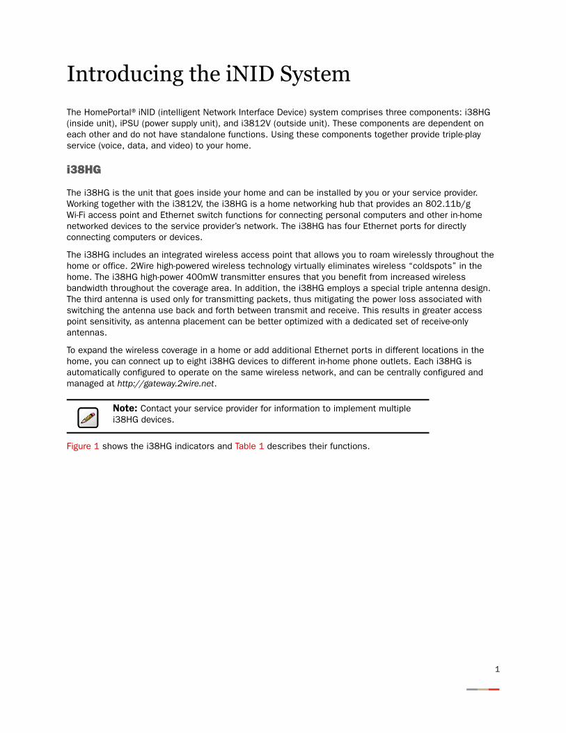
The i38HG is the unit that goes inside your home and can be installed by you or your service provider. Working together with the i3812V, the i38HG is a home networking hub that provides an 802.11b/g Wi-Fi access point and Ethernet switch functions for connecting personal computers and other in-home networked devices to the service provider’s network. The i38HG has four Ethernet ports for directly connecting computers or devices.
The i38HG includes an integrated wireless access point that allows you to roam wirelessly throughout the home or office. 2Wire high-powered wireless technology virtually eliminates wireless “coldspots” in the home. The i38HG high-power 400mW transmitter ensures that you benefit from increased wireless bandwidth throughout the coverage area. In addition, the i38HG employs a special triple antenna design. The third antenna is used only for transmitting packets, thus mitigating the power loss associated with switching the antenna use back and forth between transmit and receive. This results in greater access point sensitivity, as antenna placement can be better optimized with a dedicated set of receive-only antennas.
To expand the wireless coverage in a home or add additional Ethernet ports in different locations in the home, you can connect up to eight i38HG devices to different in-home phone outlets. Each i38HG is automatically configured to operate on the same wireless network, and can be centrally configured and managed at http://gateway.2wire.net.
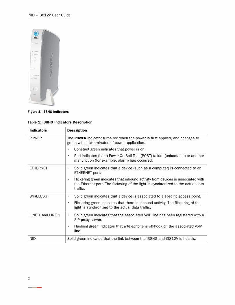
Figure 1 shows the i38HG indicators and Table 1 describes their functions.
Note: Contact your service provider for information to implement multiple i38HG devices.
1
iNID -- i3812V User Guide
Figure 1: i38HG Indicators
Table 1: i38HG Indicators Description
Indicators Description
POWER The POWER indicator turns red when the power is first applied, and changes to green within two minutes of power application.
• Constant green indicates that power is on.
• Red indicates that a Power-On Self-Test (POST) failure (unbootable) or another malfunction (for example, alarm) has occurred.
ETHERNET • Solid green indicates that a device (such as a computer) is connected to an ETHERNET port.
• Flickering green indicates that inbound activity from devices is associated with the Ethernet port. The flickering of the light is synchronized to the actual data traffic.
WIRELESS • Solid green indicates that a device is associated to a specific access point.
• Flickering green indicates that there is inbound activity. The flickering of the light is synchronized to the actual data traffic.
LINE 1 and LINE 2 • Solid green indicates that the associated VoIP line has been registered with a SIP proxy server.
• Flashing green indicates that a telephone is off-hook on the associated VoIP line.
NID Solid green indicates that the link between the i38HG and i3812V is healthy.
NID
ETHERNET
WIRELESS
LINE 1
LINE 2
SERVICE
POWER
BROADBAND
i38HG
2
Introducing the iNID System
iPSU
The Power Supply Unit (iPSU) supplies power to the i3812V and is installed by your service provider. The iPSU optimum operating temperature is between –5o C to +50o C, ambient (23.0o F to 122o F). Unlike the i3812V, the iPSU must be installed in a sheltered area — either inside the garage or home. If the iPSU is equipped with a backup battery, during a temporary AC power outage, the power source is switched to the battery without interruption of the voice-over-IP service. When the AC power is restored, the power source is switched back to the AC power supply. The switchover between the AC power supply and the battery is automatic and instantaneous.
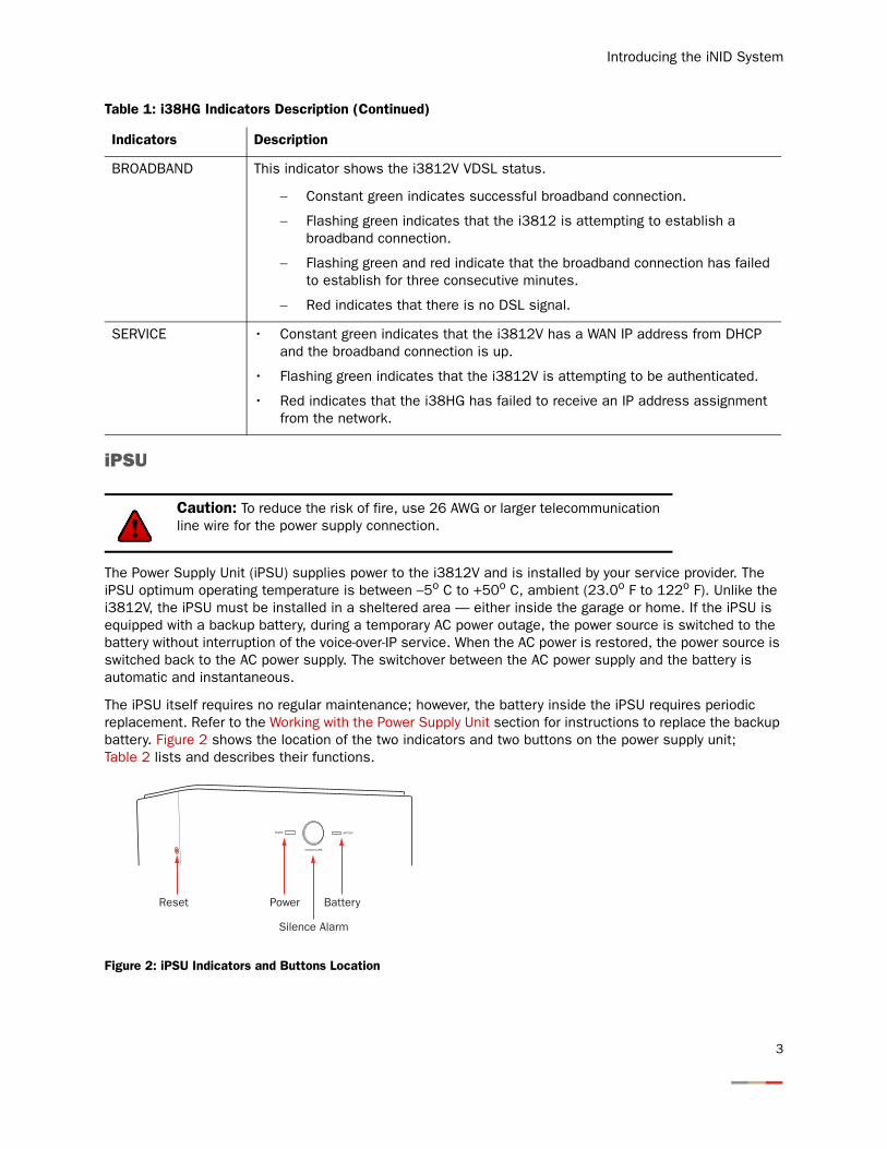
The iPSU itself requires no regular maintenance; however, the battery inside the iPSU requires periodic replacement. Refer to the Working with the Power Supply Unit section for instructions to replace the backup battery. Figure 2 shows the location of the two indicators and two buttons on the power supply unit; Table 2 lists and describes their functions.
Figure 2: iPSU Indicators and Buttons Location
BROADBAND This indicator shows the i3812V VDSL status.
− Constant green indicates successful broadband connection.
− Flashing green indicates that the i3812 is attempting to establish a broadband connection.
− Flashing green and red indicate that the broadband connection has failed to establish for three consecutive minutes.
− Red indicates that there is no DSL signal.
SERVICE • Constant green indicates that the i3812V has a WAN IP address from DHCP and the broadband connection is up.
• Flashing green indicates that the i3812V is attempting to be authenticated.
• Red indicates that the i38HG has failed to receive an IP address assignment from the network.
Caution: To reduce the risk of fire, use 26 AWG or larger telecommunication line wire for the power supply connection.
Table 1: i38HG Indicators Description (Continued)
Indicators Description
3
iNID -- i3812V User Guide
Note: The battery provides power for voice over IP services during a power outage. You are responsible to monitor and replace the battery when needed. Your service provide does not monitor the battery and is not responsible for its replacement.
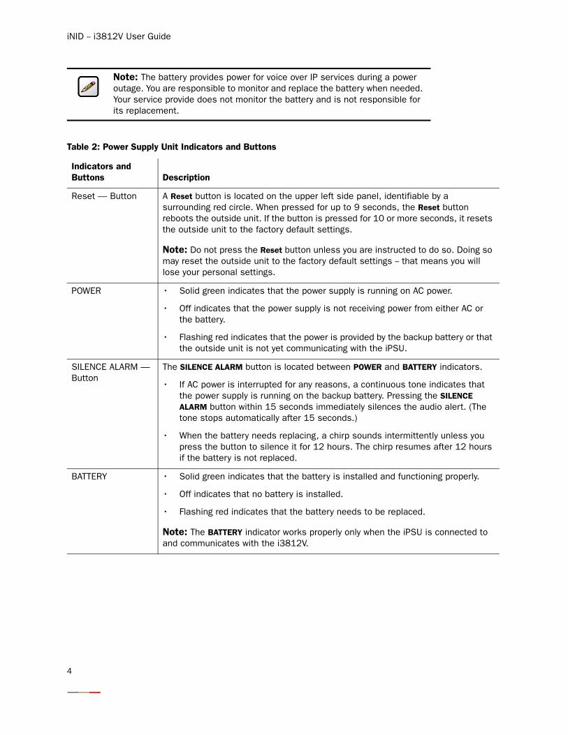
Table 2: Power Supply Unit Indicators and Buttons
Indicators and Buttons Description
Reset — Button A Reset button is located on the upper left side panel, identifiable by a surrounding red circle. When pressed for up to 9 seconds, the Reset button reboots the outside unit. If the button is pressed for 10 or more seconds, it resets the outside unit to the factory default settings.
Note: Do not press the Reset button unless you are instructed to do so. Doing so may reset the outside unit to the factory default settings -- that means you will lose your personal settings.
POWER • Solid green indicates that the power supply is running on AC power.
• Off indicates that the power supply is not receiving power from either AC or the battery.
• Flashing red indicates that the power is provided by the backup battery or that the outside unit is not yet communicating with the iPSU.
SILENCE ALARM — Button
The SILENCE ALARM button is located between POWER and BATTERY indicators.
• If AC power is interrupted for any reasons, a continuous tone indicates that the power supply is running on the backup battery. Pressing the SILENCE ALARM button within 15 seconds immediately silences the audio alert. (The tone stops automatically after 15 seconds.)
• When the battery needs replacing, a chirp sounds intermittently unless you press the button to silence it for 12 hours. The chirp resumes after 12 hours if the battery is not replaced.
BATTERY • Solid green indicates that the battery is installed and functioning properly.
• Off indicates that no battery is installed.
• Flashing red indicates that the battery needs to be replaced.
Note: The BATTERY indicator works properly only when the iPSU is connected to and communicates with the i3812V.
4
Introducing the iNID System
i3812V
The i3812V is the gateway that acts as the network interface device. It is installed by your service provider on the outside of your home. The i3812V includes a broadband interface and high-speed coaxial and phone line network capabilities to deliver data service to the home. The i3812V has two accessible areas: one for service provider personnel and the other for subscribers.
Service Provider Access
The service provider access area is locked and can be opened only by the service provider personnel. The i3812V has two cable entries providing wiring from the service provider and to inside your home. The left entry provides cable connection from the service provider to the i3812V. The right entry provides wiring that feeds the inside of your home and power connection for the power supply unit.
Subscriber Access
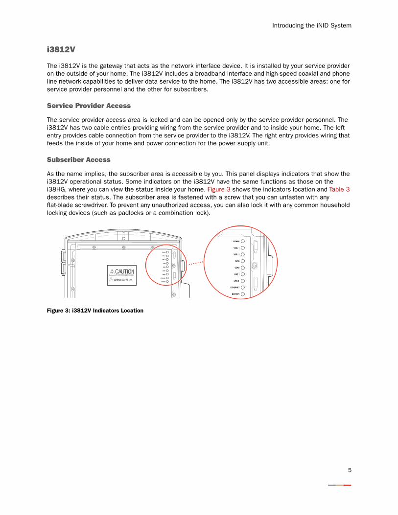
As the name implies, the subscriber area is accessible by you. This panel displays indicators that show the i3812V operational status. Some indicators on the i3812V have the same functions as those on the i38HG, where you can view the status inside your home. Figure 3 shows the indicators location and Table 3 describes their status. The subscriber area is fastened with a screw that you can unfasten with any flat-blade screwdriver. To prevent any unauthorized access, you can also lock it with any common household locking devices (such as padlocks or a combination lock).
Figure 3: i3812V Indicators Location
POWER
VDSL 1
VDSL 2
DATA
COAX
LINE 1
LINE 2
ETHERNET
BATTERY
POWER
VDSL 1
VDSL 2
DATA
COAX
LINE 1
LINE 2
ETHERNET
BATTERY
5
iNID -- i3812V User Guide
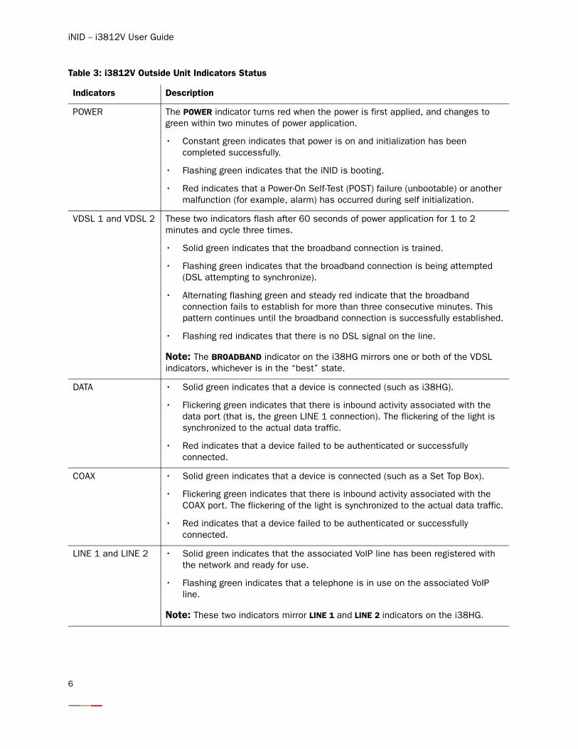
Table 3: i3812V Outside Unit Indicators Status
Indicators Description
POWER The POWER indicator turns red when the power is first applied, and changes to green within two minutes of power application.
• Constant green indicates that power is on and initialization has been completed successfully.
• Flashing green indicates that the iNID is booting.
• Red indicates that a Power-On Self-Test (POST) failure (unbootable) or another malfunction (for example, alarm) has occurred during self initialization.
VDSL 1 and VDSL 2 These two indicators flash after 60 seconds of power application for 1 to 2 minutes and cycle three times.
• Solid green indicates that the broadband connection is trained.
• Flashing green indicates that the broadband connection is being attempted (DSL attempting to synchronize).
• Alternating flashing green and steady red indicate that the broadband connection fails to establish for more than three consecutive minutes. This pattern continues until the broadband connection is successfully established.
• Flashing red indicates that there is no DSL signal on the line.
Note: The BROADBAND indicator on the i38HG mirrors one or both of the VDSL indicators, whichever is in the “best” state.
DATA • Solid green indicates that a device is connected (such as i38HG).
• Flickering green indicates that there is inbound activity associated with the data port (that is, the green LINE 1 connection). The flickering of the light is synchronized to the actual data traffic.
• Red indicates that a device failed to be authenticated or successfully connected.
COAX • Solid green indicates that a device is connected (such as a Set Top Box).
• Flickering green indicates that there is inbound activity associated with the COAX port. The flickering of the light is synchronized to the actual data traffic.
• Red indicates that a device failed to be authenticated or successfully connected.
LINE 1 and LINE 2 • Solid green indicates that the associated VoIP line has been registered with the network and ready for use.
• Flashing green indicates that a telephone is in use on the associated VoIP line.
Note: These two indicators mirror LINE 1 and LINE 2 indicators on the i38HG.
6
Introducing the iNID System
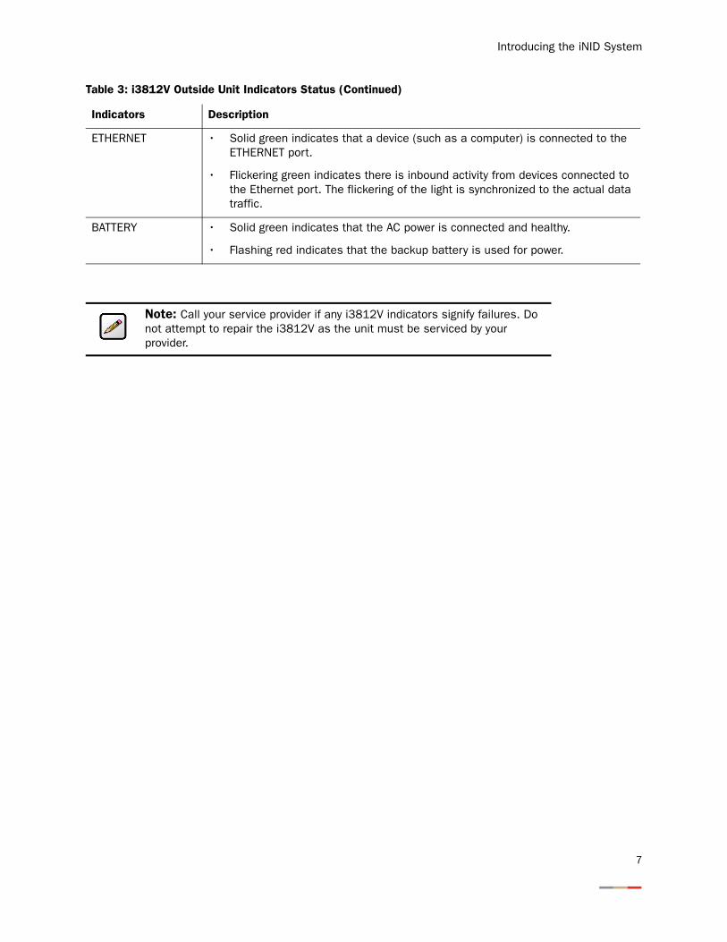
ETHERNET • Solid green indicates that a device (such as a computer) is connected to the ETHERNET port.
• Flickering green indicates there is inbound activity from devices connected to the Ethernet port. The flickering of the light is synchronized to the actual data traffic.
BATTERY • Solid green indicates that the AC power is connected and healthy.
• Flashing red indicates that the backup battery is used for power.
Note: Call your service provider if any i3812V indicators signify failures. Do not attempt to repair the i3812V as the unit must be serviced by your provider.
Table 3: i3812V Outside Unit Indicators Status (Continued)
Indicators Description
7

iNID -- i3812V User Guide
8
Installing Your i38HG
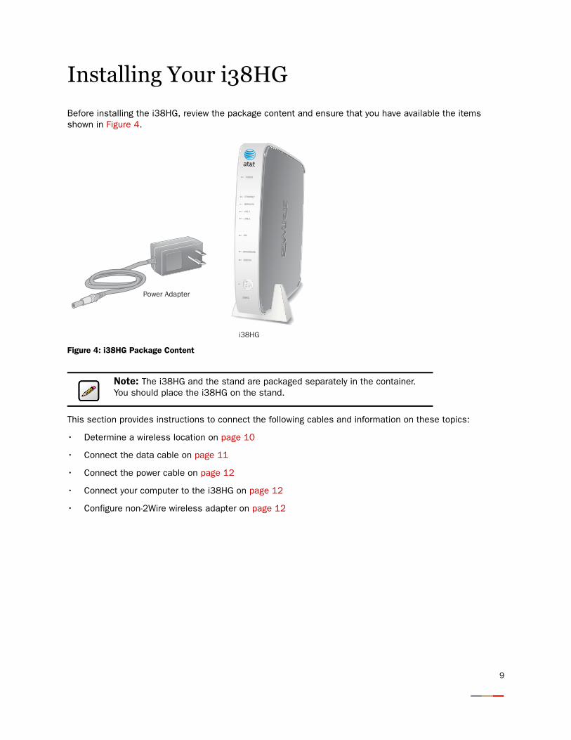
Before installing the i38HG, review the package content and ensure that you have available the items shown in Figure 4.
Figure 4: i38HG Package Content
This section provides instructions to connect the following cables and information on these topics:
• Determine a wireless location on page 10
• Connect the data cable on page 11
• Connect the power cable on page 12
• Connect your computer to the i38HG on page 12
• Configure non-2Wire wireless adapter on page 12
Note: The i38HG and the stand are packaged separately in the container. You should place the i38HG on the stand.
i38HG
Power Adapter
NID
ETHERNET
WIRELESS
LINE 1
LINE 2
SERVICE
POWER
BROADBAND
i38HG
9

iNID -- i3812V User Guide
Determining Wireless Access Points Location
Wireless signals are affected by many items in common households. Reliability and performance are the major considerations when planning your wireless network location.
Avoiding Interference
Wireless signals are subject to interference from other electronic devices including (but not limited to) microwave ovens, cordless telephones, and garage door openers. Proper installation will minimize interference. Place your i38HG at least 5 feet from cordless phones, microwaves, or other electronic devices to avoid potential interference, and more than 6 inches away from television to avoid audio hissing or static.
Avoiding Obstructions
The wireless signal degrades with distance and obstructions (such as ceilings, walls, and furniture). Consider the layout of your home or business when deciding where to place your i38HG.
• Consider where you will use your wireless devices when placing your i38HG. In a single-story building, place the i38HG as high and as close to each wireless computer as possible. To minimize interference, do not place the i38HG behind large objects or other obstructions.
• Place the i38HG in an open area where wireless range will not be directly affected by surroundings. Wireless signal strength will be much stronger in an open area as opposed to an area with obstructions.
• Keep the i38HG away from any large metal objects. Because metal objects can reflect or obstruct signals, wireless signal quality and speed may be adversely impacted.
Note: Whenever possible, use the stand provided with the i38HG and install it in the vertical position. If that is not possible, be sure that it is installed in a manner that nothing can be stacked on the top of it. The i38HG generates substantial amounts of heat and could possibly damage something that is stacked on it.
10
Installing Your i38HG
Connecting the Data Cable
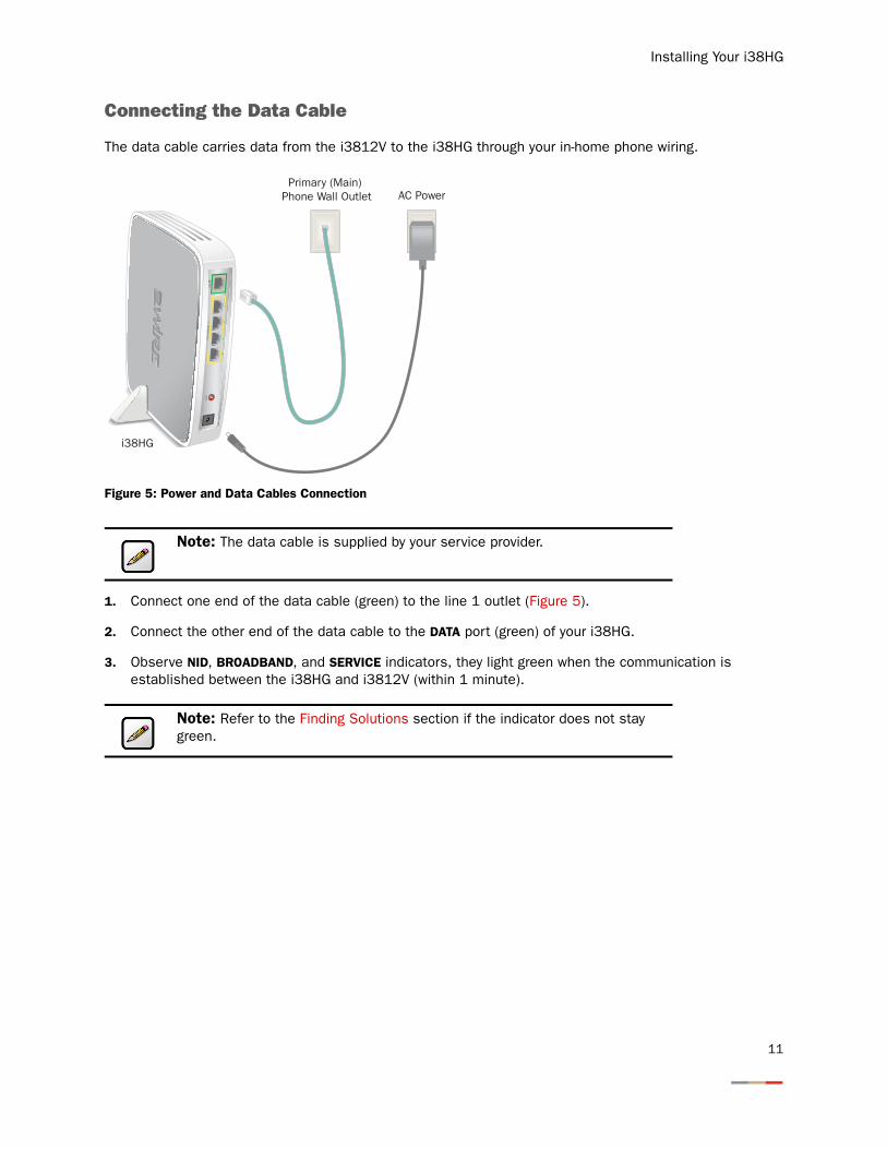
The data cable carries data from the i3812V to the i38HG through your in-home phone wiring.
Figure 5: Power and Data Cables Connection
1. Connect one end of the data cable (green) to the line 1 outlet (Figure 5).
2. Connect the other end of the data cable to the DATA port (green) of your i38HG.
3. Observe NID, BROADBAND, and SERVICE indicators, they light green when the communication is established between the i38HG and i3812V (within 1 minute).
Note: The data cable is supplied by your service provider.
Note: Refer to the Finding Solutions section if the indicator does not stay green.
DATA
POW
ER
RESE
TLO
CAL
ETHE
RNET
i38HG
AC PowerPrimary (Main)
Phone Wall Outlet
11
iNID -- i3812V User Guide
Connecting the Power Cable
1. Connect one end of the power supply cable to the POWER port of your i38HG (Figure 4).
2. Connect the other end of power supply cable to a 3-prong AC electrical outlet.
3. Observe the POWER indicator; it flashes red once, followed by flashing green, then remains solid green.
Connecting Your Computer to the i38HG
There are two ways to connect your computer to the i38HG: via Ethernet or wireless. With either connection, the first computer you connect to the network is used to configure the i38HG for proper operation.
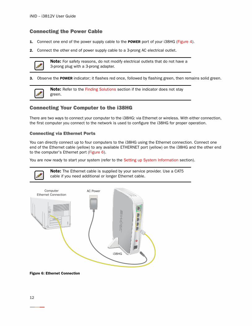
Connecting via Ethernet Ports
You can directly connect up to four computers to the i38HG using the Ethernet connection. Connect one end of the Ethernet cable (yellow) to any available ETHERNET port (yellow) on the i38HG and the other end to the computer's Ethernet port (Figure 6).
You are now ready to start your system (refer to the Setting up System Information section).
Figure 6: Ethernet Connection
Note: For safety reasons, do not modify electrical outlets that do not have a 3-prong plug with a 3-prong adapter.
Note: Refer to the Finding Solutions section if the indicator does not stay green.
Note: The Ethernet cable is supplied by your service provider. Use a CAT5 cable if you need additional or longer Ethernet cable.
DATA
POW
ER
RESE
TLO
CAL
ETHE
RNET
ComputerEthernet Connection
i38HG
AC Power
12
Installing Your i38HG
Connecting via Wireless
Your i38HG has an integrated wireless access point (AP) that enables you to connect your wireless-enabled computers to your home network. By default, the i38HG is shipped with WPA-PSK and WPA2-PSK enabled and a preconfigured network name. Refer to the Configuring Wireless Network section to configure your wireless network.
You can connect up to eight i38HGs (that is, APs) in your home. When multiple APs are detected, they are automatically synchronized across all managed access points to create a single wireless network for easier device connectivity. The default service set identifier (SSID) and wireless key is based on the last three digits of the serial number on the first access point that was connected. If you have multiple APs installed, refer to the label on your first installed AP only. All subsequent access points are automatically synchronized with the default SSID or with any custom SSID you define subsequent to initial installation.
Most laptop computers are equipped with an internal 802.11b/g card. If your computer is not equipped with an internal card, you can install an external wireless adapter for wireless networking. The 2Wire wireless adapter provides a 2Wire Setup Wizard that automatically configures it to communicate with the i38HG during setup. If you are using a non-2Wire wireless adapter, you must manually configure it to communicate with the i38HG. Refer to the Configuring non-2Wire Wireless Adapters section to install a wireless network adapter.
Configuring non-2Wire Wireless Adapters
If you are using a non-2Wire wireless adapter, you must manually configure it to communicate with the i38HG. This section provides instructions to configure your adapter with WPA. You can use WEP if your wireless adapter does not support WPA; however, this decreases the level of security provided for wireless traffic.
1. Install and configure your wireless adapter according to the manufacturer’s instructions.
2. Use the network adapter configuration software or Windows network connection wizard to set the network name (SSID) and encryption key (WPA).
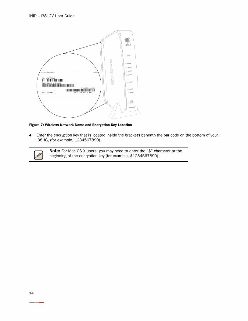
3. Enter 2WIRE (in capital letters) as the network name, followed by the last three digits of the i38HG serial number (for example, 2WIRE110), located on the bottom of your i38HG (Figure 7).
Note: If you have multiple APs, use the last three digits of the first i38HG connected to the network.
13
iNID -- i3812V User Guide
Figure 7: Wireless Network Name and Encryption Key Location
4. Enter the encryption key that is located inside the brackets beneath the bar code on the bottom of your i38HG, (for example, 1234567890).
Note: For Mac OS X users, you may need to enter the “$” character at the beginning of the encryption key (for example, $1234567890).
14
Setting up System Information
After the i38HG is properly connected and the first time you access the i3812V user interface, it is a good idea to change the default password. You do not need to adjust the local date and time as they are set nightly by the service provider.
This section provides the browser requirements and instructions to:
• Navigate the user interface on page 16
• Set up your password on page 18
Meeting Web Browser Requirements
• Microsoft Internet Explorer 6.0 or higher
• Firefox 1.5 or higher
• Safari 2.0
15
iNID -- i3812V User Guide
Navigating the User Interface
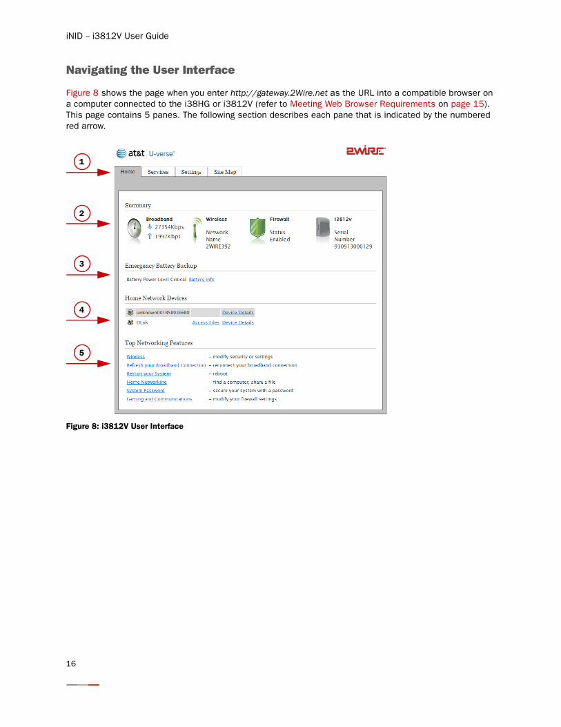
Figure 8 shows the page when you enter http://gateway.2Wire.net as the URL into a compatible browser on a computer connected to the i38HG or i3812V (refer to Meeting Web Browser Requirements on page 15). This page contains 5 panes. The following section describes each pane that is indicated by the numbered red arrow.
Figure 8: i3812V User Interface
1
2
3
4
5
16
Setting up System Information
1. The tab pane of the user interface contains the following four tabs that are arranged horizontally. Clicking any of these tabs displays a page that enables you to access associated information.
− Home: The Home tab provides the most relevant information about your broadband service at a glance. It also provides links to access more detailed information (Figure 8).
− Services: The Services tab provides links to view your voice line status.
− Settings: The Settings tab provides the most comprehensive system information. Clicking this tab opens a page that provides sub-tabs to access other pages to configure your i38HG and view system status.
− Site Map: The Site Map tab provides a textual view of the user interface. Clicking any links on this page takes you directly to the page of interest.
2. The Summary pane displays the status of each service. Except the fourth icon, i3812V, you can click other icons to directly access more information.
3. This pane displays the backup battery status. You can click Battery Info to directly access the page.
4. The Home Network Devices pane displays all devices that are connected to the i38HG. You can click the links to view the detailed information of the connected devices.
5. The Top Networking Features pane provides shortcuts to directly access the most commonly used pages.
Notes: The backup battery status is displayed only if your iPSU is equipped with one.
It is recommended to have a backup battery if you subscribe to voice-over-IP services and is required to maintain voice-over-IP service during a power outage.
17
iNID -- i3812V User Guide
Setting up Your Password
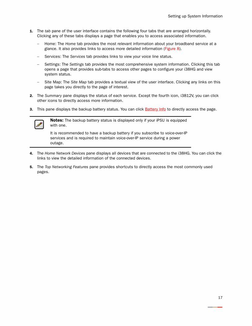
The default system password is automatically set five minutes after the iPSU is connected. You can find the default system password on the iPSU front cover.
Setting a system password protects your i3812V settings from being modified or changed by someone who has not been given permission to do so. After setting a system password, you will be required to enter it whenever you attempt to access a configuration page (for example, when you try to change the broadband connection settings).
To set up a password:
1. Open a Web browser and enter http://gateway.2Wire.net to access the 2Wire i3812V user interface.
18
Setting up System Information
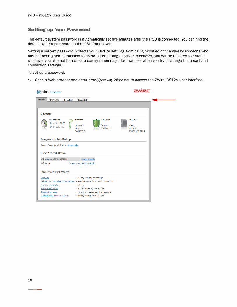
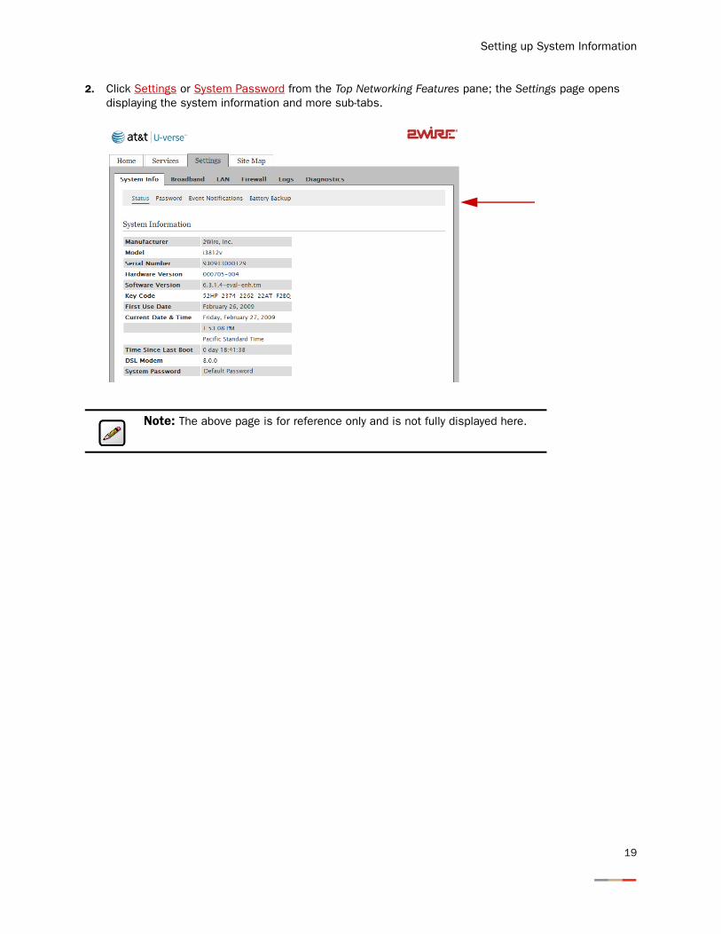
2. Click Settings or System Password from the Top Networking Features pane; the Settings page opens displaying the system information and more sub-tabs.
Note: The above page is for reference only and is not fully displayed here.
19
iNID -- i3812V User Guide
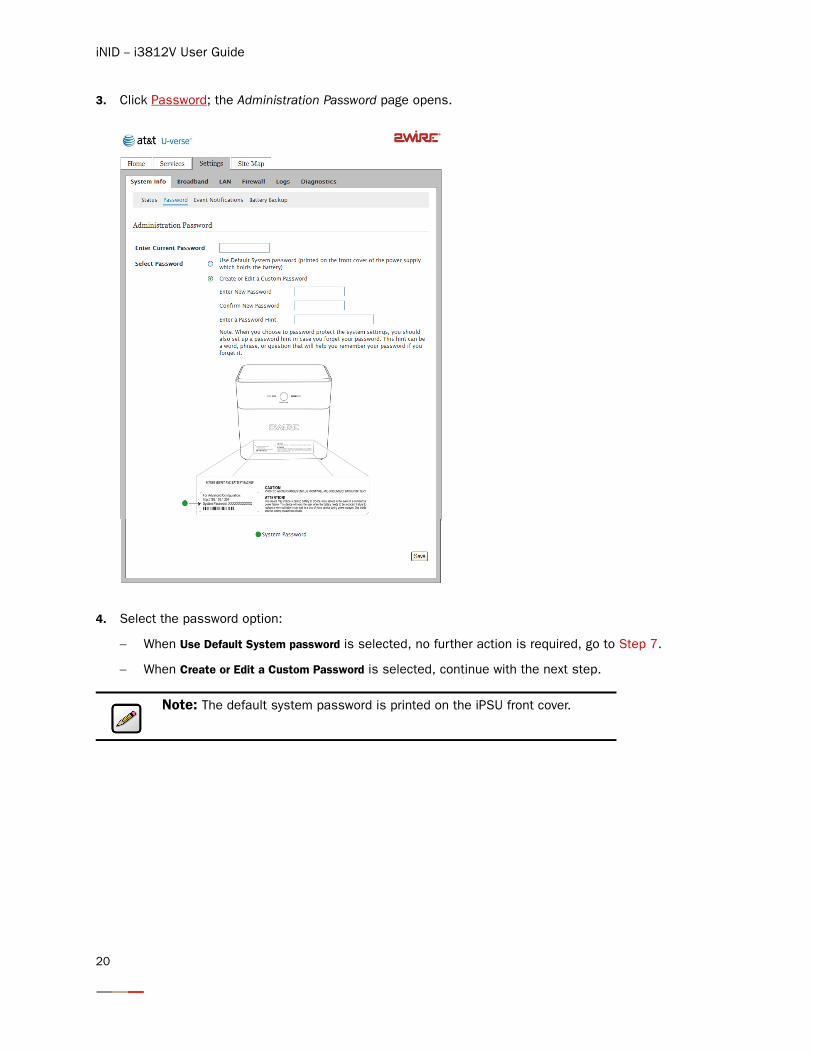
3. Click Password; the Administration Password page opens.
4. Select the password option:
− When Use Default System password is selected, no further action is required, go to Step 7.
− When Create or Edit a Custom Password is selected, continue with the next step.
Note: The default system password is printed on the iPSU front cover.
20
Setting up System Information
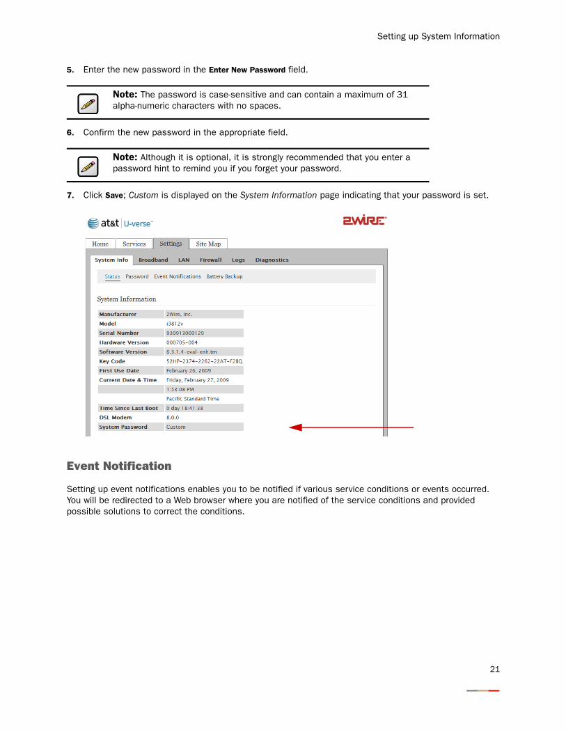
5. Enter the new password in the Enter New Password field.
6. Confirm the new password in the appropriate field.
7. Click Save; Custom is displayed on the System Information page indicating that your password is set.
Event Notification
Setting up event notifications enables you to be notified if various service conditions or events occurred. You will be redirected to a Web browser where you are notified of the service conditions and provided possible solutions to correct the conditions.
Note: The password is case-sensitive and can contain a maximum of 31 alpha-numeric characters with no spaces.
Note: Although it is optional, it is strongly recommended that you enter a password hint to remind you if you forget your password.
21
iNID -- i3812V User Guide
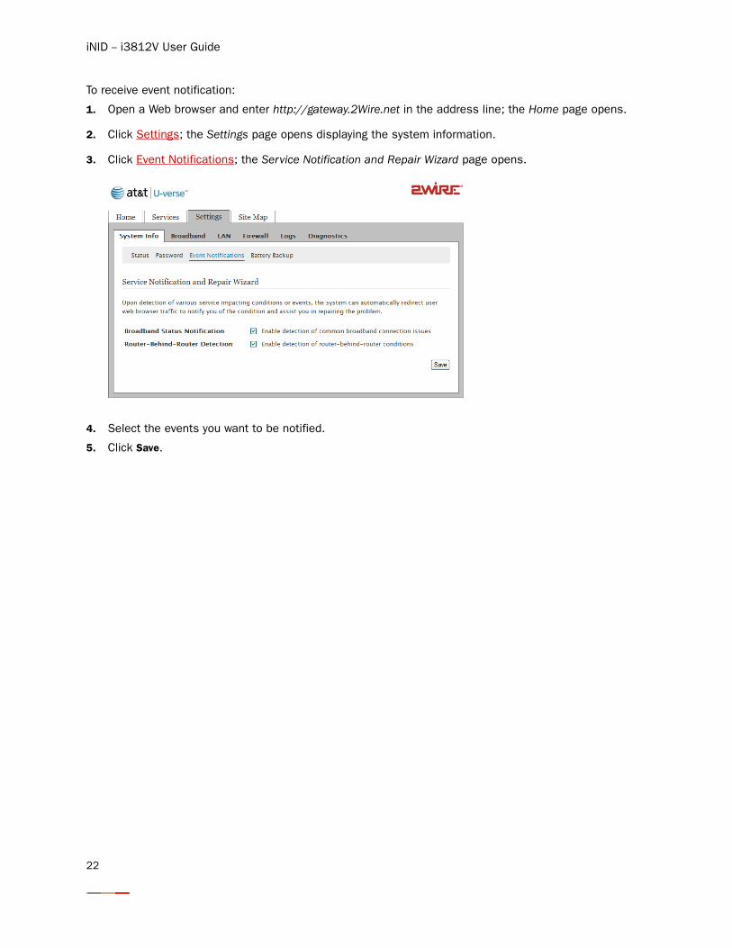
To receive event notification:
1. Open a Web browser and enter http://gateway.2Wire.net in the address line; the Home page opens.
2. Click Settings; the Settings page opens displaying the system information.
3. Click Event Notifications; the Service Notification and Repair Wizard page opens.
4. Select the events you want to be notified.
5. Click Save.
22
Configuring Wireless Network
When the i38HG is properly installed, the wireless network is functional. Your i38HG is preconfigured with settings that optimize wireless performance. It is recommended that you leave the default settings in place.
If you are knowledgeable with the wireless technology and want to modify the settings, this section provides instructions to perform the following advanced configurations:
• Select the wireless access point on page 24
• Set up your wireless network name on page 25
• Secure your wireless network on page 26
• Customize personal wireless settings on page 34
• Configuring Wi-Fi Protection Setup on page 35
23
iNID -- i3812V User Guide
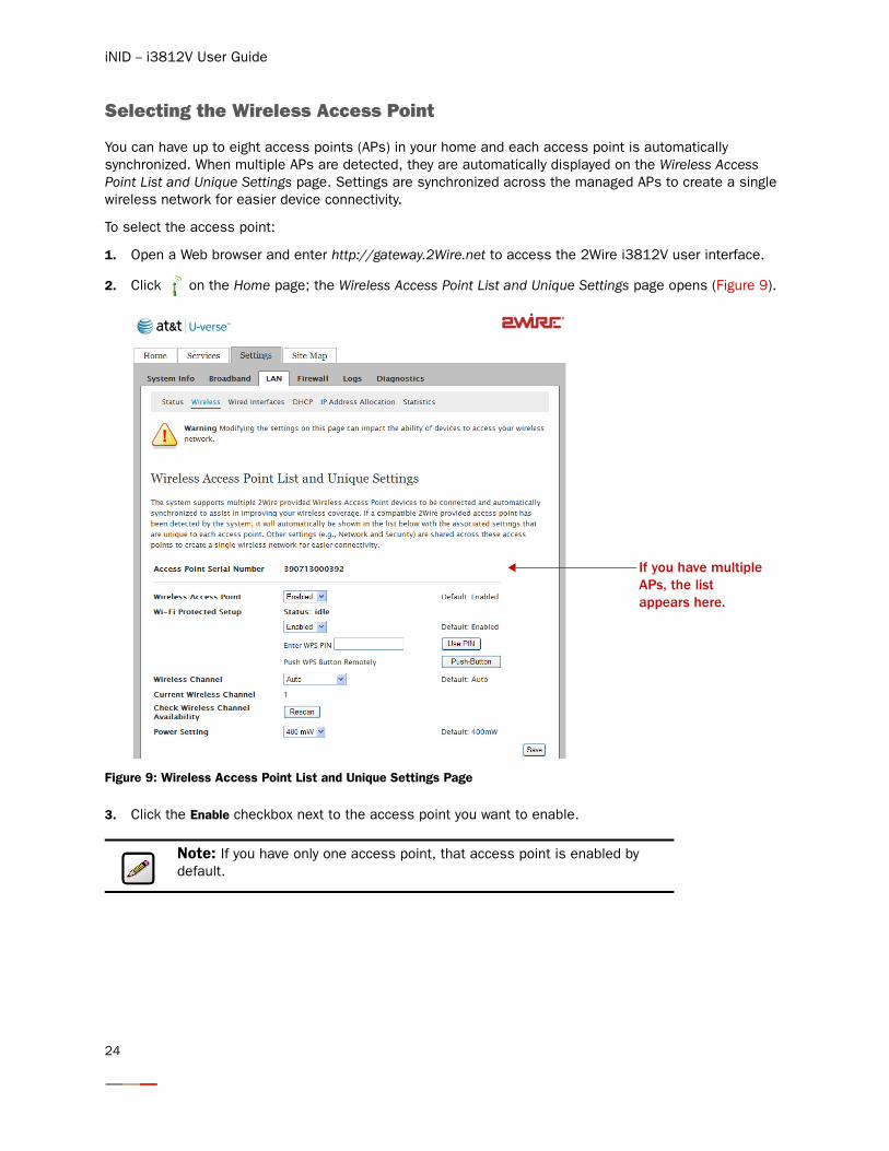
Selecting the Wireless Access Point
You can have up to eight access points (APs) in your home and each access point is automatically synchronized. When multiple APs are detected, they are automatically displayed on the Wireless Access Point List and Unique Settings page. Settings are synchronized across the managed APs to create a single wireless network for easier device connectivity.
To select the access point:
1. Open a Web browser and enter http://gateway.2Wire.net to access the 2Wire i3812V user interface.
2. Click on the Home page; the Wireless Access Point List and Unique Settings page opens (Figure 9).
Figure 9: Wireless Access Point List and Unique Settings Page
3. Click the Enable checkbox next to the access point you want to enable.
Note: If you have only one access point, that access point is enabled by default.
If you have multiple APs, the list appears here.
24
Configuring Wireless Network
4. Select the channel (radio frequency band) the access point uses for your wireless network.
5. Select the power level for your wireless connection from the Power drop-down list. The default is 400 mW.
6. Click Save.
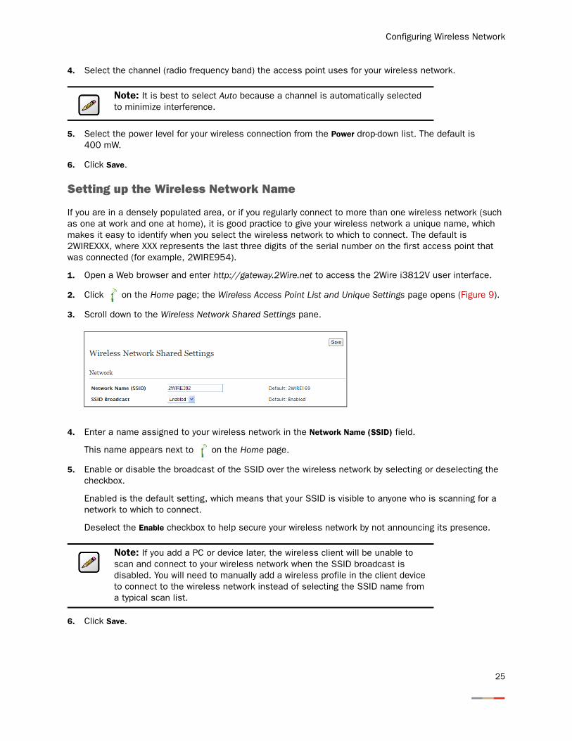
Setting up the Wireless Network Name
If you are in a densely populated area, or if you regularly connect to more than one wireless network (such as one at work and one at home), it is good practice to give your wireless network a unique name, which makes it easy to identify when you select the wireless network to which to connect. The default is 2WIREXXX, where XXX represents the last three digits of the serial number on the first access point that was connected (for example, 2WIRE954).
1. Open a Web browser and enter http://gateway.2Wire.net to access the 2Wire i3812V user interface.
2. Click on the Home page; the Wireless Access Point List and Unique Settings page opens (Figure 9).
3. Scroll down to the Wireless Network Shared Settings pane.
4. Enter a name assigned to your wireless network in the Network Name (SSID) field.
This name appears next to on the Home page.
5. Enable or disable the broadcast of the SSID over the wireless network by selecting or deselecting the checkbox.
Enabled is the default setting, which means that your SSID is visible to anyone who is scanning for a network to which to connect.
Deselect the Enable checkbox to help secure your wireless network by not announcing its presence.
6. Click Save.
Note: It is best to select Auto because a channel is automatically selected to minimize interference.
Note: If you add a PC or device later, the wireless client will be unable to scan and connect to your wireless network when the SSID broadcast is disabled. You will need to manually add a wireless profile in the client device to connect to the wireless network instead of selecting the SSID name from a typical scan list.
25
iNID -- i3812V User Guide
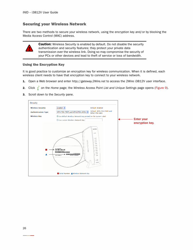
Securing your Wireless Network
There are two methods to secure your wireless network, using the encryption key and/or by blocking the Media Access Control (MAC) address.
Using the Encryption Key
It is good practice to customize an encryption key for wireless communication. When it is defined, each wireless client needs to have that encryption key to connect to your wireless network.
1. Open a Web browser and enter http://gateway.2Wire.net to access the 2Wire i3812V user interface.
2. Click on the Home page; the Wireless Access Point List and Unique Settings page opens (Figure 9).
3. Scroll down to the Security pane.
Caution: Wireless Security is enabled by default. Do not disable the security authentication and security features; they protect your private data transmission over the wireless link. Doing so may compromise the security of your PCs or other devices and lead to theft of service or loss of bandwidth.
Enter your encryption key.
26
Configuring Wireless Network
4. Select an authentication setting from the Authentication Type drop-down list:
− WEP-Open. The Wireless Encryption Protocol (WEP) is an older security protocol that allows any wireless clients within the radio range to access your network without an encryption key. This setting provides the least level of security. For security reasons, do not select this setting unless there is a compatibility issue with an older wireless client. For added protection, set an encryption key on your AP and enter the same key into your other wireless clients.
− WEP-Shared. Similar to the WEP-Open setting, do not select this setting unless there is a compatibility issue with an older wireless client. Unlike the WEP-Open setting, the WEP-Shared setting prevents open access by any wireless client; therefore, it is more secure than the WEP-Open setting. For added protection, set an encryption key on your AP and enter the same key into your other wireless clients.
− WPA-PSK. This setting provides good security and works with most wireless clients but perhaps not some older clients. This setting requires that an encryption key to be set on the AP and that the wireless client be configured to use Wi-Fi Protected Access – Pre-Shared Key (WPA-PSK) with the same encryption key.
− WPA-PSK (TKIP) and WPA2-PSK (AES). This is the default setting. This setting allows a wireless client to use either WPA-PSK or WPA2-PSK to access your network. An encryption key must be configured on the AP and the same key must be entered on the wireless client.
− WPA2-PSK. This setting requires that wireless clients use only WPA2-PSK to access your networks. An encryption key must be configured on the AP and entered into the wireless client. WPA2-PSK is currently the most secure Wi-Fi encryption protocol but may not be available on many wireless clients.
5. Select Use custom Wireless Network Key and enter a security key in the field.
This security key will be used by all clients to access your wireless network. You can define a 64-bit or 128-bit encryption key. For 64-bit encryption, enter a 10-digit hexadecimal number. For 128-bit encryption, enter a 26-digit hexadecimal number. A hexadecimal number uses the characters 0-9, a-f, or A-F.
Using the MAC Address Filtering
The MAC address is a factory-programmed address assigned to each hardware device. The MAC address filtering feature enables you to block or allow wireless connection to all devices or an individual device. It is most often used to allow only “known and trusted” devices to associate to the AP. By default, the MAC address filtering is disabled, meaning that all discovered devices are allowed. When enabled, the wireless connection is blocked to all MAC addresses.
Note: Check the capabilities of the wireless clients that will be accessing this network and find the most secure protocol that is supported by all.
27
iNID -- i3812V User Guide
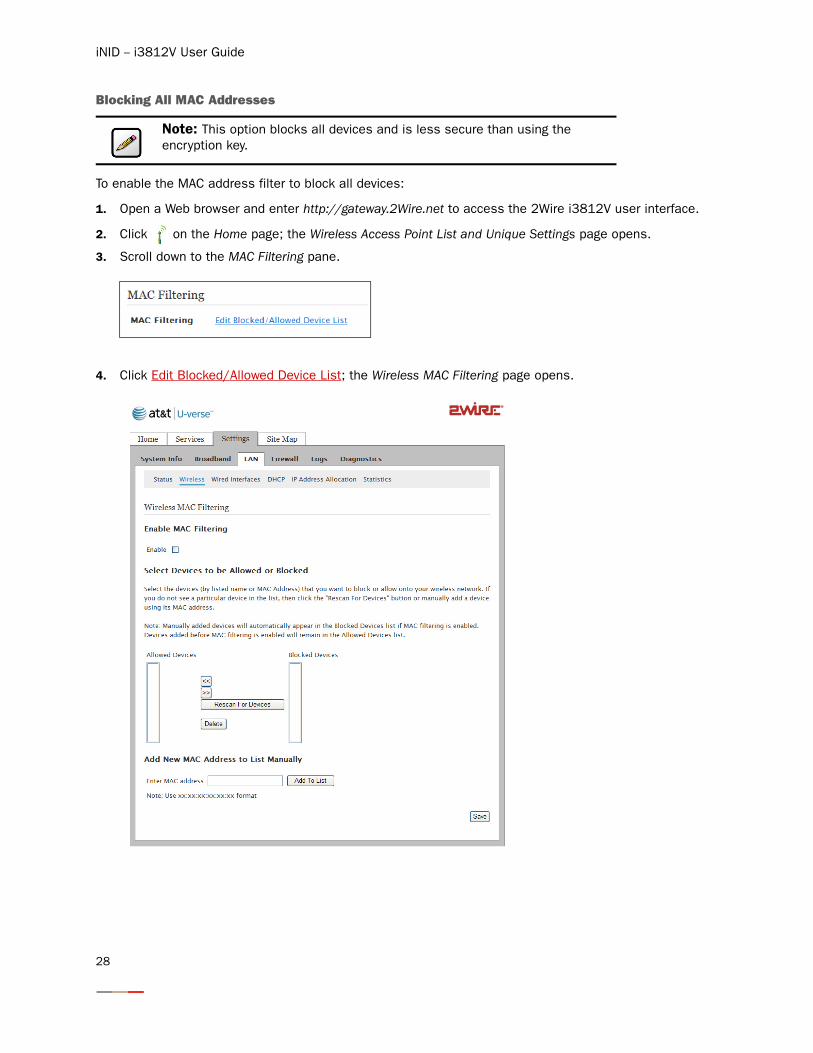
Blocking All MAC Addresses
To enable the MAC address filter to block all devices:
1. Open a Web browser and enter http://gateway.2Wire.net to access the 2Wire i3812V user interface.
2. Click on the Home page; the Wireless Access Point List and Unique Settings page opens.
3. Scroll down to the MAC Filtering pane.
4. Click Edit Blocked/Allowed Device List; the Wireless MAC Filtering page opens.
Note: This option blocks all devices and is less secure than using the encryption key.
28
Configuring Wireless Network
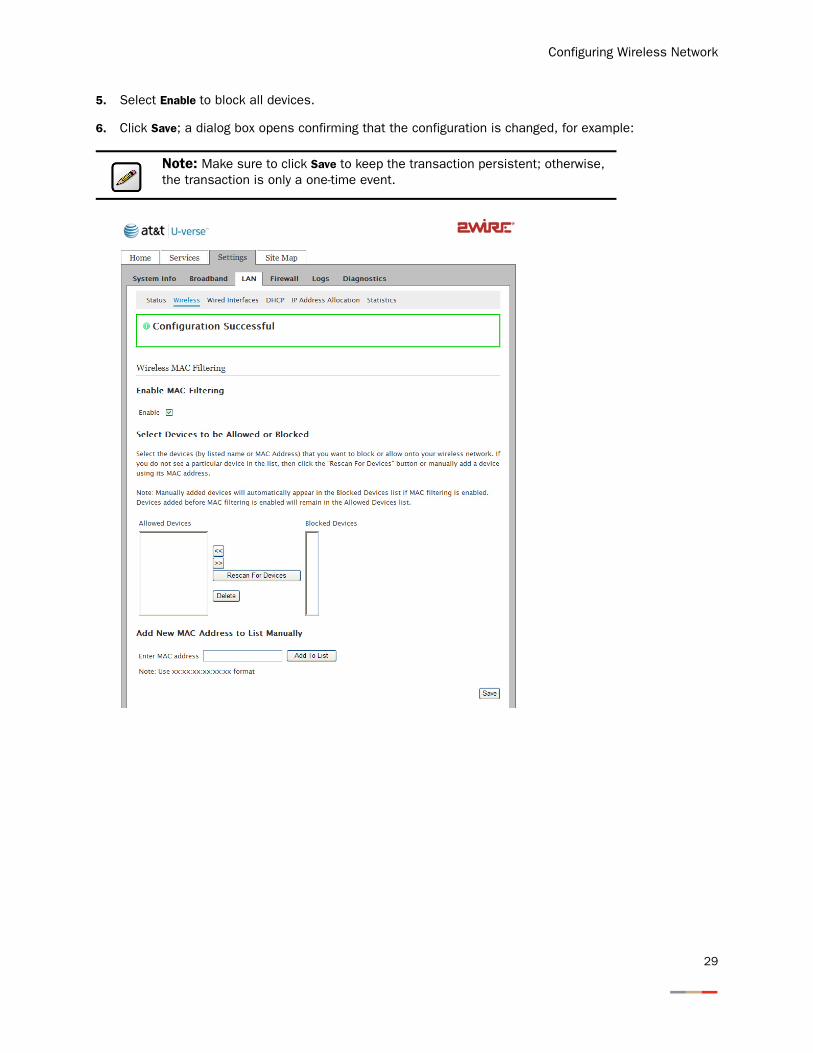
5. Select Enable to block all devices.
6. Click Save; a dialog box opens confirming that the configuration is changed, for example:
Note: Make sure to click Save to keep the transaction persistent; otherwise, the transaction is only a one-time event.
29
iNID -- i3812V User Guide
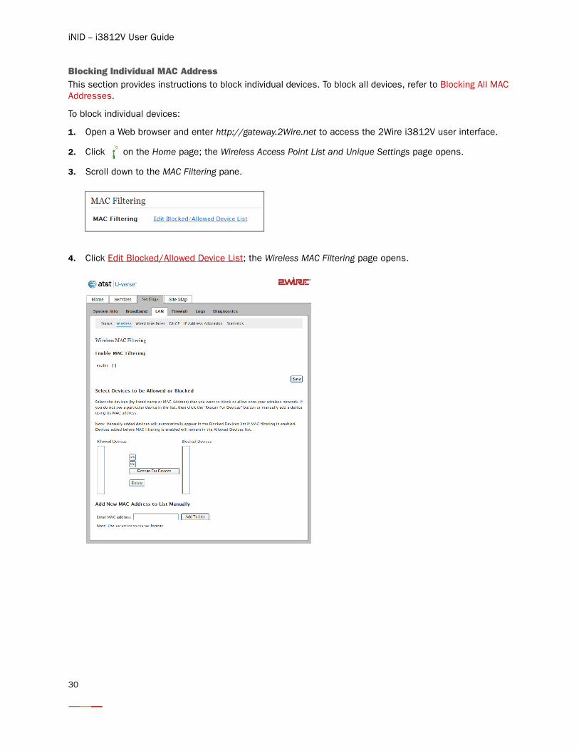
Blocking Individual MAC Address This section provides instructions to block individual devices. To block all devices, refer to Blocking All MAC Addresses.
To block individual devices:
1. Open a Web browser and enter http://gateway.2Wire.net to access the 2Wire i3812V user interface.
2. Click on the Home page; the Wireless Access Point List and Unique Settings page opens.
3. Scroll down to the MAC Filtering pane.
4. Click Edit Blocked/Allowed Device List; the Wireless MAC Filtering page opens.
30
Configuring Wireless Network
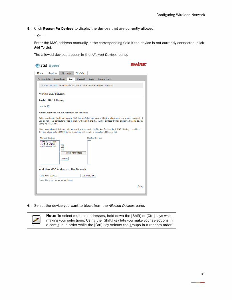
5. Click Rescan For Devices to display the devices that are currently allowed.
– Or –
Enter the MAC address manually in the corresponding field if the device is not currently connected, click Add To List.
The allowed devices appear in the Allowed Devices pane.
6. Select the device you want to block from the Allowed Devices pane.
Note: To select multiple addresses, hold down the [Shift] or [Ctrl] keys while making your selections. Using the [Shift] key lets you make your selections in a contiguous order while the [Ctrl] key selects the groups in a random order.
31
iNID -- i3812V User Guide
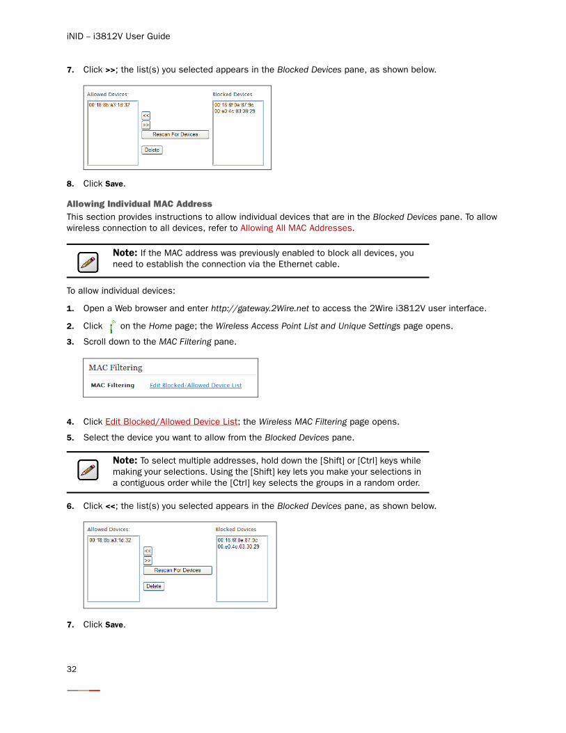
7. Click >>; the list(s) you selected appears in the Blocked Devices pane, as shown below.
8. Click Save.
Allowing Individual MAC AddressThis section provides instructions to allow individual devices that are in the Blocked Devices pane. To allow wireless connection to all devices, refer to Allowing All MAC Addresses.
To allow individual devices:
1. Open a Web browser and enter http://gateway.2Wire.net to access the 2Wire i3812V user interface.
2. Click on the Home page; the Wireless Access Point List and Unique Settings page opens.
3. Scroll down to the MAC Filtering pane.
4. Click Edit Blocked/Allowed Device List; the Wireless MAC Filtering page opens.
5. Select the device you want to allow from the Blocked Devices pane.
6. Click <<; the list(s) you selected appears in the Blocked Devices pane, as shown below.
7. Click Save.
Note: If the MAC address was previously enabled to block all devices, you need to establish the connection via the Ethernet cable.
Note: To select multiple addresses, hold down the [Shift] or [Ctrl] keys while making your selections. Using the [Shift] key lets you make your selections in a contiguous order while the [Ctrl] key selects the groups in a random order.
32
Configuring Wireless Network
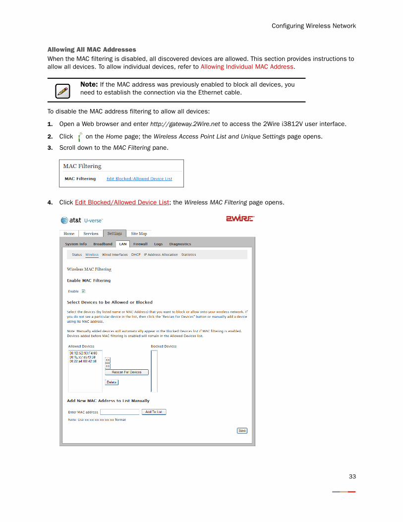
Allowing All MAC AddressesWhen the MAC filtering is disabled, all discovered devices are allowed. This section provides instructions to allow all devices. To allow individual devices, refer to Allowing Individual MAC Address.
To disable the MAC address filtering to allow all devices:
1. Open a Web browser and enter http://gateway.2Wire.net to access the 2Wire i3812V user interface.
2. Click on the Home page; the Wireless Access Point List and Unique Settings page opens.
3. Scroll down to the MAC Filtering pane.
4. Click Edit Blocked/Allowed Device List; the Wireless MAC Filtering page opens.
Note: If the MAC address was previously enabled to block all devices, you need to establish the connection via the Ethernet cable.
33
iNID -- i3812V User Guide
5. Deselect the Enable checkbox to allow wireless connection to all devices.
6. Click Save.
Customize Private Wireless Settings
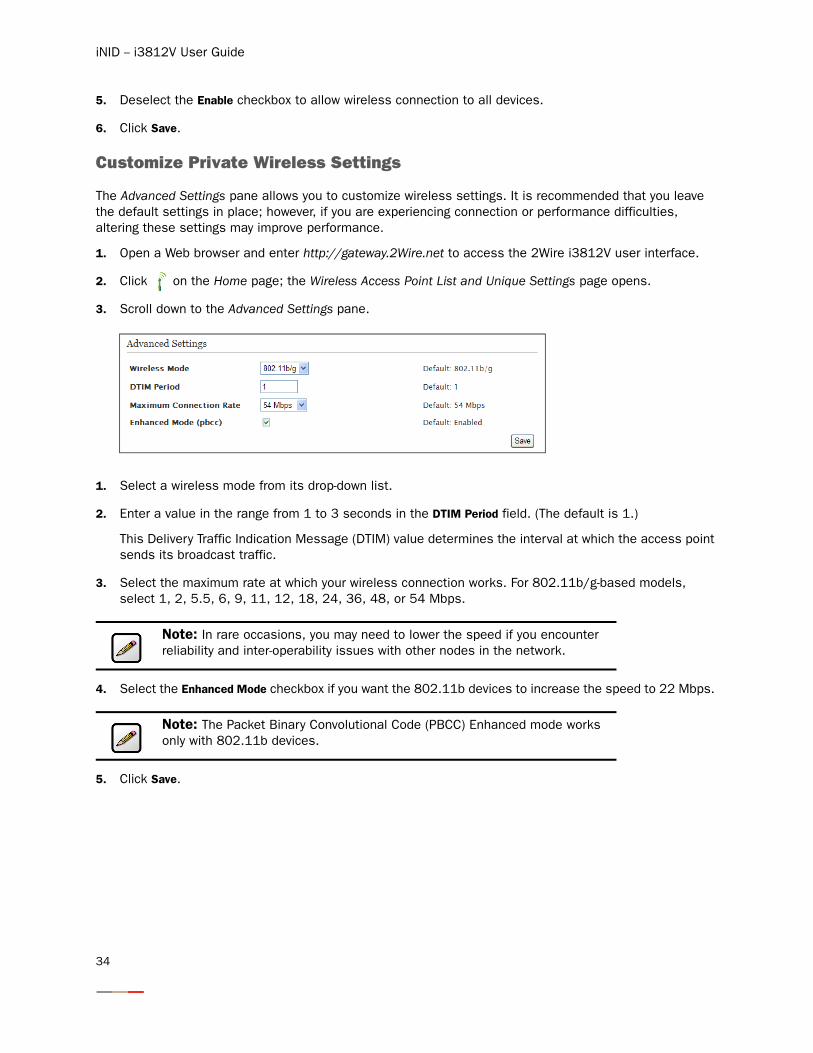
The Advanced Settings pane allows you to customize wireless settings. It is recommended that you leave the default settings in place; however, if you are experiencing connection or performance difficulties, altering these settings may improve performance.
1. Open a Web browser and enter http://gateway.2Wire.net to access the 2Wire i3812V user interface.
2. Click on the Home page; the Wireless Access Point List and Unique Settings page opens.
3. Scroll down to the Advanced Settings pane.
1. Select a wireless mode from its drop-down list.
2. Enter a value in the range from 1 to 3 seconds in the DTIM Period field. (The default is 1.)
This Delivery Traffic Indication Message (DTIM) value determines the interval at which the access point sends its broadcast traffic.
3. Select the maximum rate at which your wireless connection works. For 802.11b/g-based models, select 1, 2, 5.5, 6, 9, 11, 12, 18, 24, 36, 48, or 54 Mbps.
4. Select the Enhanced Mode checkbox if you want the 802.11b devices to increase the speed to 22 Mbps.
5. Click Save.
Note: In rare occasions, you may need to lower the speed if you encounter reliability and inter-operability issues with other nodes in the network.
Note: The Packet Binary Convolutional Code (PBCC) Enhanced mode works only with 802.11b devices.
34
Configuring Wireless Network
Configuring Wi-Fi Protected Setup
The i38HG supports Wi-Fi Protected Setup (WPS), which is a standard for easy and secure establishment of a wireless home network. Using WPS simplifies the process of connecting any home device to the wireless network. As an AP, the i38HG issues and revokes credentials to a network. The i38HG provides a push button on the front panel to enable the synchronization between the AP and the client (analogous to the pairing of the garage door opener and remote control).
WPS supports both push button and PIN-based configuration methods with the access point functions as a standalone registrar. When either method is enabled, the gateway automatically detects the presence of a WPS-enabled client device. Both methods require WPA or WPA2 security enabled and the predefined passphrase is provided to the WPS device.
Using the Push Button Method
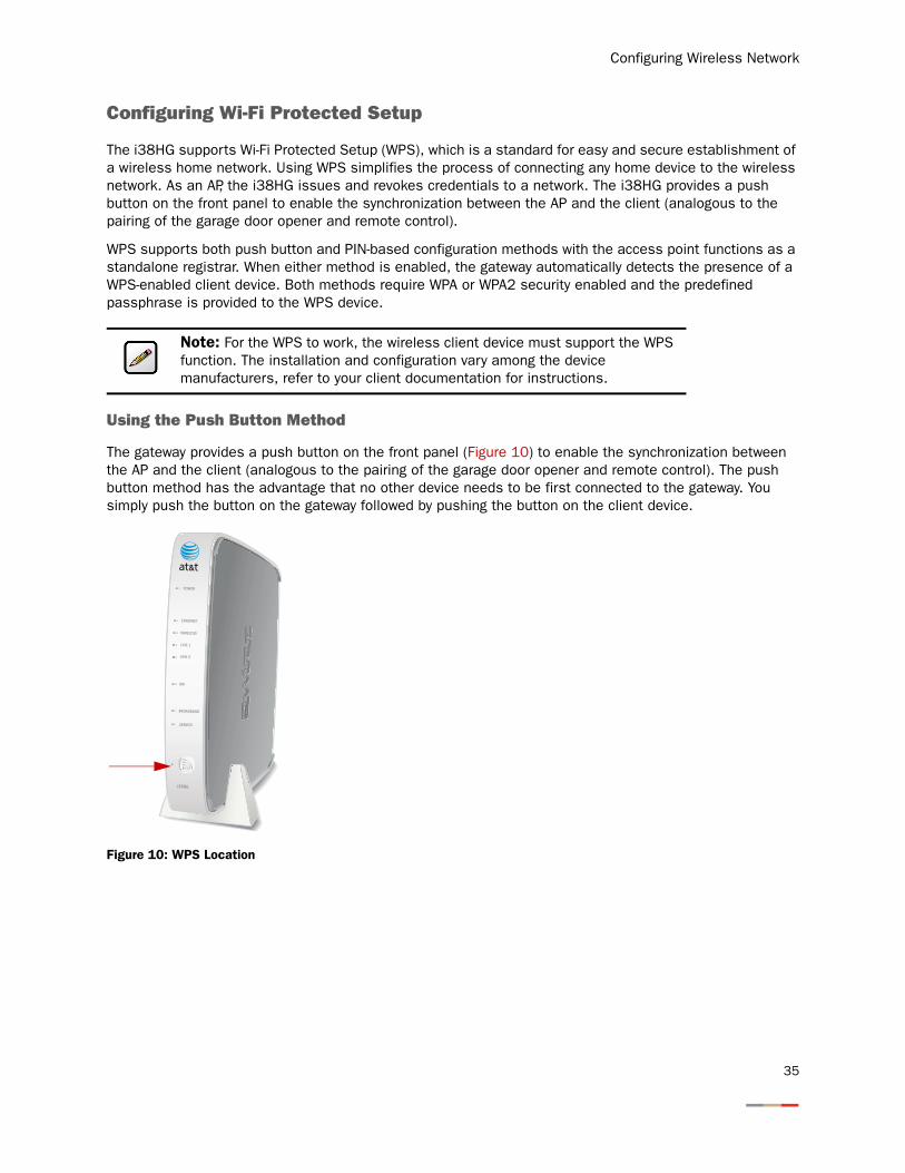
The gateway provides a push button on the front panel (Figure 10) to enable the synchronization between the AP and the client (analogous to the pairing of the garage door opener and remote control). The push button method has the advantage that no other device needs to be first connected to the gateway. You simply push the button on the gateway followed by pushing the button on the client device.
Figure 10: WPS Location
Note: For the WPS to work, the wireless client device must support the WPS function. The installation and configuration vary among the device manufacturers, refer to your client documentation for instructions.
NID
ETHERNET
WIRELESS
LINE 1
LINE 2
SERVICE
POWER
BROADBAND
i38HG
35
iNID -- i3812V User Guide
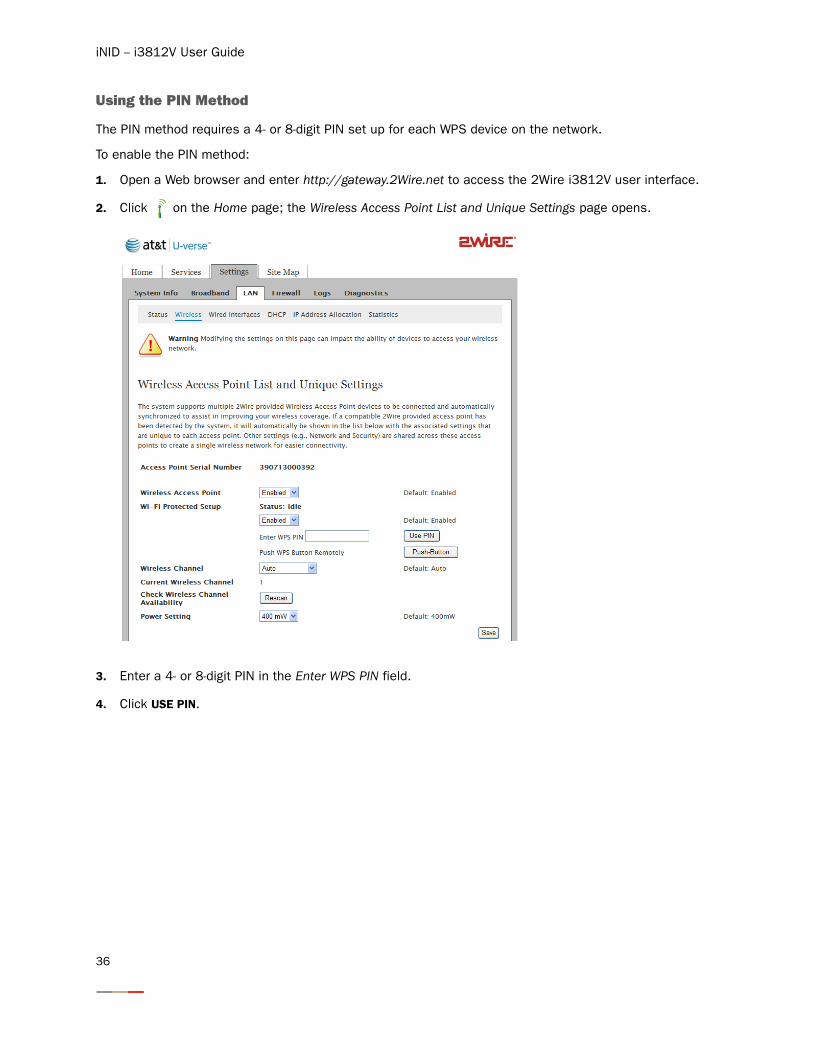
Using the PIN Method
The PIN method requires a 4- or 8-digit PIN set up for each WPS device on the network.
To enable the PIN method:
1. Open a Web browser and enter http://gateway.2Wire.net to access the 2Wire i3812V user interface.
2. Click on the Home page; the Wireless Access Point List and Unique Settings page opens.
3. Enter a 4- or 8-digit PIN in the Enter WPS PIN field.
4. Click USE PIN.
36
Configuring Firewall
The i3812V includes default firewall settings that block unwanted access from the Internet; it is recommended that you leave the default settings in place. If necessary, you can allow Internet traffic or users through the firewall to your LAN devices, applications, and servers. This section provides instructions to:
• Host an application on your network to allow users access on page 38
• Remove an application on your network to block users access on page 38
• Define an application profile on page 41
• Add multiple definitions to a profile on page 45
• Delete a user-defined application profile on page 48
• Allow all applications (DMZplus) on page 49
• Stop DMZplus on page 51
• Customize firewall settings on page 52
Caution: You should be knowledgeable with the firewall configuration to modify these settings; otherwise, you are exposing your computer to outside attacks.
37
iNID -- i3812V User Guide
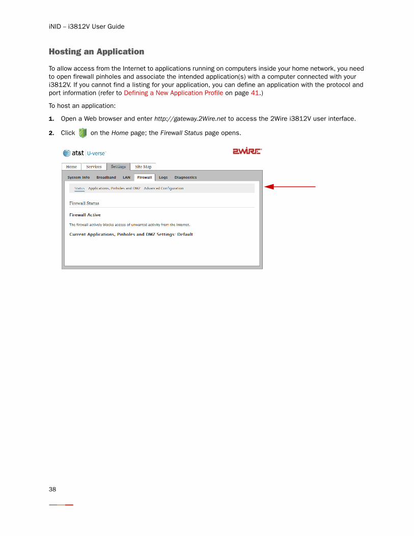
Hosting an Application
To allow access from the Internet to applications running on computers inside your home network, you need to open firewall pinholes and associate the intended application(s) with a computer connected with your i3812V. If you cannot find a listing for your application, you can define an application with the protocol and port information (refer to Defining a New Application Profile on page 41.)
To host an application:
1. Open a Web browser and enter http://gateway.2Wire.net to access the 2Wire i3812V user interface.
2. Click on the Home page; the Firewall Status page opens.
38
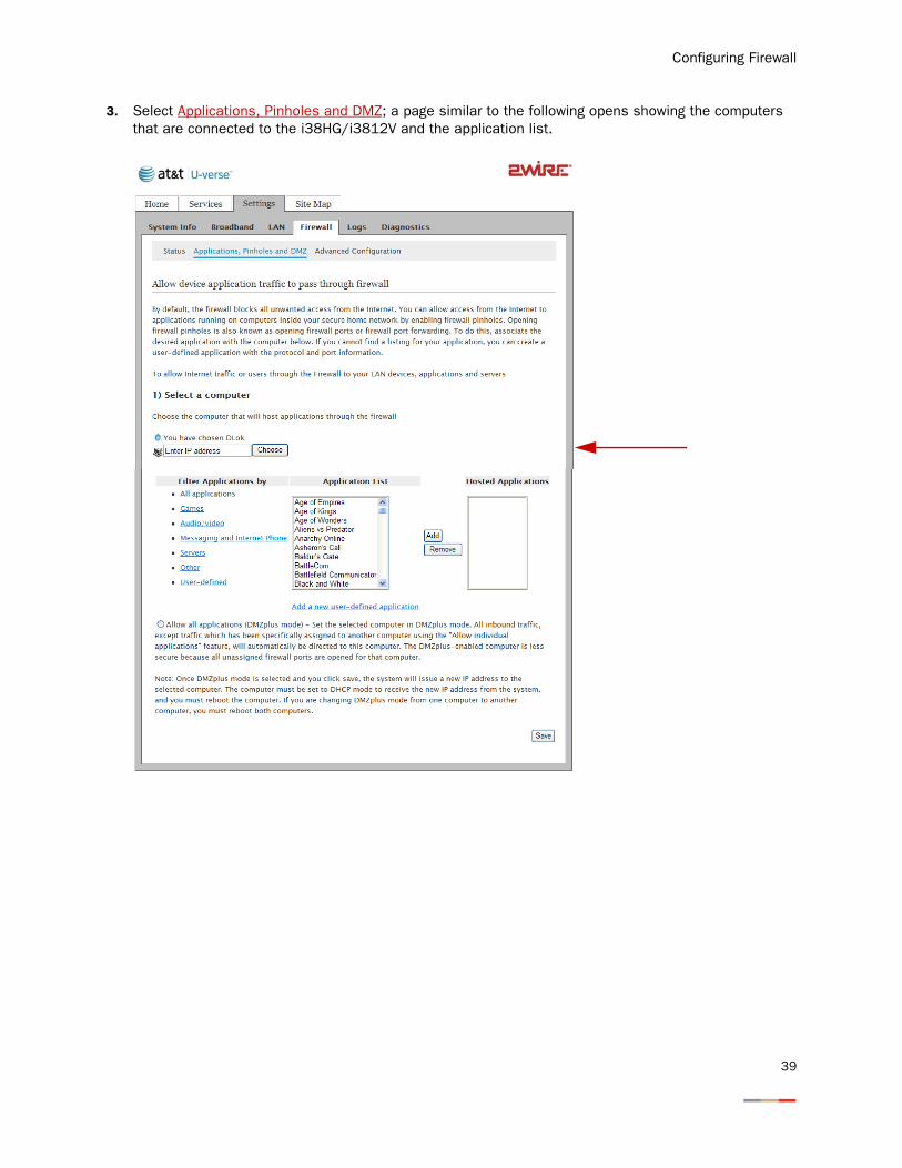
Configuring Firewall
3. Select Applications, Pinholes and DMZ; a page similar to the following opens showing the computers that are connected to the i38HG/i3812V and the application list.
39
iNID -- i3812V User Guide
4. Select the computer that you want to host the application(s).
5. Select Allow individual application(s).
6. Filter the application list by selecting the category; your selection is displayed in the Application List panel.
7. Select from the Application List panel the application(s) you want to host.
8. Click Add; the application(s) you selected appears in the Hosted Applications panel.
9. Click Save; a message appears informing you the status.
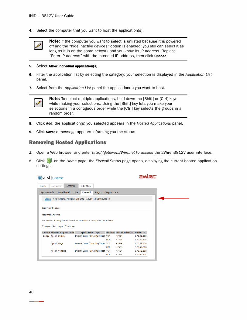
Removing Hosted Applications
1. Open a Web browser and enter http://gateway.2Wire.net to access the 2Wire i3812V user interface.
2. Click on the Home page; the Firewall Status page opens, displaying the current hosted application settings.
Note: If the computer you want to select is unlisted because it is powered off and the “hide inactive devices” option is enabled; you still can select it as long as it is on the same network and you know its IP address. Replace “Enter IP address” with the intended IP address, then click Choose.
Note: To select multiple applications, hold down the [Shift] or [Ctrl] keys while making your selections. Using the [Shift] key lets you make your selections in a contiguous order while the [Ctrl] key selects the groups in a random order.
40
Configuring Firewall
3. Select Applications, Pinholes and DMZ; a page opens showing hosted applications.
4. Select the hosting computer if you do not see the pinhole you want to remove in the list.
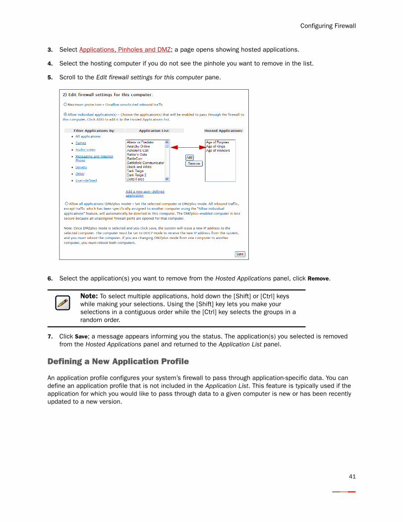
5. Scroll to the Edit firewall settings for this computer pane.
6. Select the application(s) you want to remove from the Hosted Applications panel, click Remove.
7. Click Save; a message appears informing you the status. The application(s) you selected is removed from the Hosted Applications panel and returned to the Application List panel.
Defining a New Application Profile
An application profile configures your system’s firewall to pass through application-specific data. You can define an application profile that is not included in the Application List. This feature is typically used if the application for which you would like to pass through data to a given computer is new or has been recently updated to a new version.
Note: To select multiple applications, hold down the [Shift] or [Ctrl] keys while making your selections. Using the [Shift] key lets you make your selections in a contiguous order while the [Ctrl] key selects the groups in a random order.
41
iNID -- i3812V User Guide
To add a new application profile:
1. Open a Web browser and enter http://gateway.2Wire.net to access the 2Wire i3812V user interface.
2. Click on the Home page; the Firewall Status page opens.
3. Select Applications, Pinholes and DMZ; a page opens showing the computers that are connected to your i38HG/i3812V and the application list.
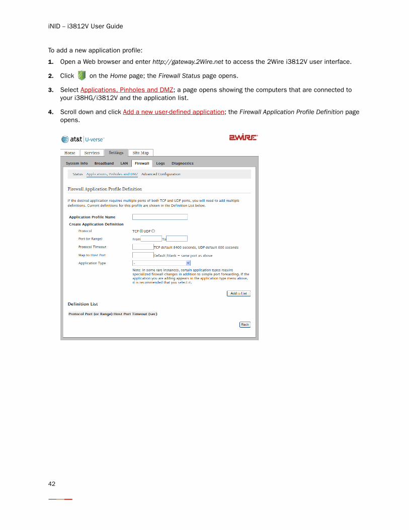
4. Scroll down and click Add a new user-defined application; the Firewall Application Profile Definition page opens.
42
Configuring Firewall
5. Enter the application profile name in the Application Profile Name field.
6. Create a definition for your application that is to be allowed through the firewall.
− In the Protocol field, select the TCP or UDP radio button. If the application you are adding requires both, you need to create a separate definition for each.
− In the Port (or Range) field, enter the port or port range the application uses. For example, some applications requires only one port to be opened (such as TCP port 500); others require that all TCP ports from 600 to 1000 be opened.
− In the Protocol Timeout (seconds) field, optionally enter a value for the amount of time that can pass before the application “times out.” When leaving the field blank, the system uses the default values (86400 seconds for the TCP protocol; 600 seconds for the UDP protocol).
− In the Map to Host Port field, enter a value that maps the port range you established in the Port field to the local computer. For example, if you set the value to 4000 and the port range being opened is 100 to 108, the forwarded data to the first value in the range will be sent to 4000. Subsequent ports will be mapped accordingly; 101 will be sent to 4001, 102 will be sent to 4002, and so forth.
− From the Application Type drop-down list, select the application type. If you do not know the application type, select nothing.
Notes: For easy identification, use the name of the application (for example, Redwing Game Server).
Clicking Back returns to the Allow device application traffic to pass through firewall page.
Note: If only one port is required, enter the port number in the From field.
Note: You can find the above information in the documentation provided by the company that produces the application.
43
iNID -- i3812V User Guide
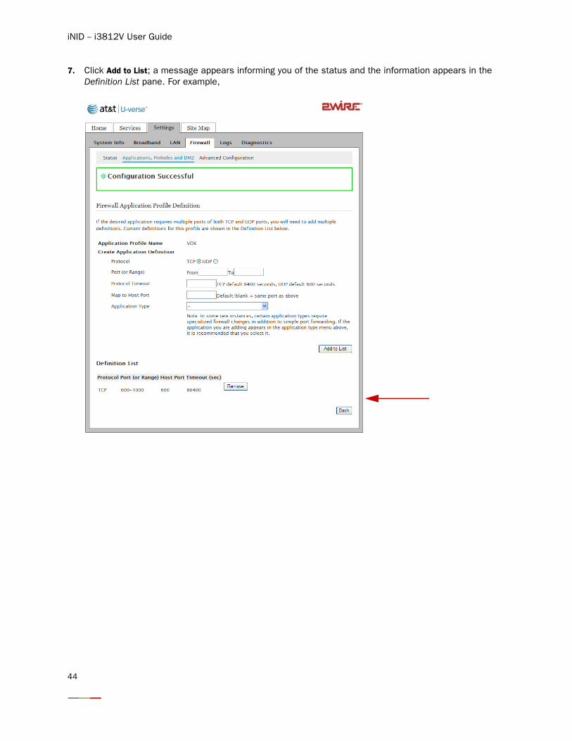
7. Click Add to List; a message appears informing you of the status and the information appears in the Definition List pane. For example,
44
Configuring Firewall
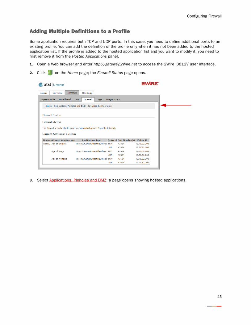
Adding Multiple Definitions to a Profile
Some application requires both TCP and UDP ports. In this case, you need to define additional ports to an existing profile. You can add the definition of the profile only when it has not been added to the hosted application list. If the profile is added to the hosted application list and you want to modify it, you need to first remove it from the Hosted Applications panel.
1. Open a Web browser and enter http://gateway.2Wire.net to access the 2Wire i3812V user interface.
2. Click on the Home page; the Firewall Status page opens.
3. Select Applications, Pinholes and DMZ; a page opens showing hosted applications.
45
iNID -- i3812V User Guide
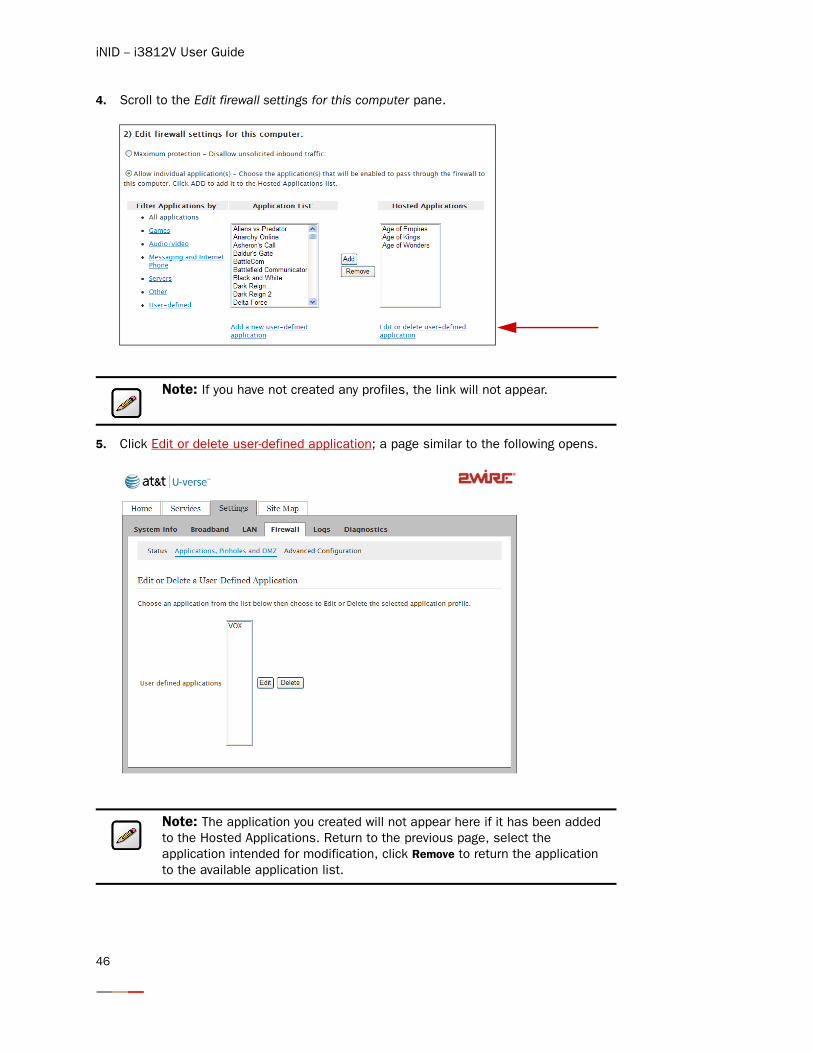
4. Scroll to the Edit firewall settings for this computer pane.
5. Click Edit or delete user-defined application; a page similar to the following opens.
Note: If you have not created any profiles, the link will not appear.
Note: The application you created will not appear here if it has been added to the Hosted Applications. Return to the previous page, select the application intended for modification, click Remove to return the application to the available application list.
46
Configuring Firewall
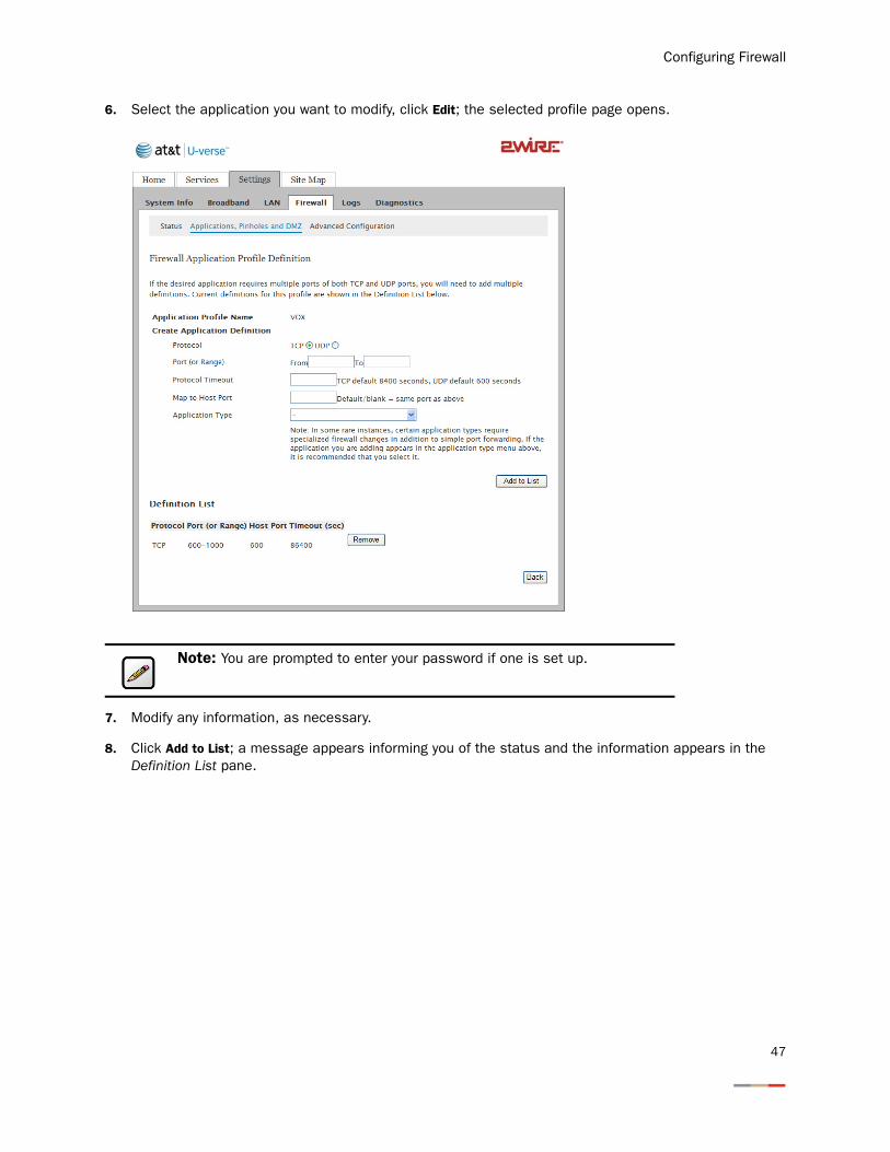
6. Select the application you want to modify, click Edit; the selected profile page opens.
7. Modify any information, as necessary.
8. Click Add to List; a message appears informing you of the status and the information appears in the Definition List pane.
Note: You are prompted to enter your password if one is set up.
47
iNID -- i3812V User Guide
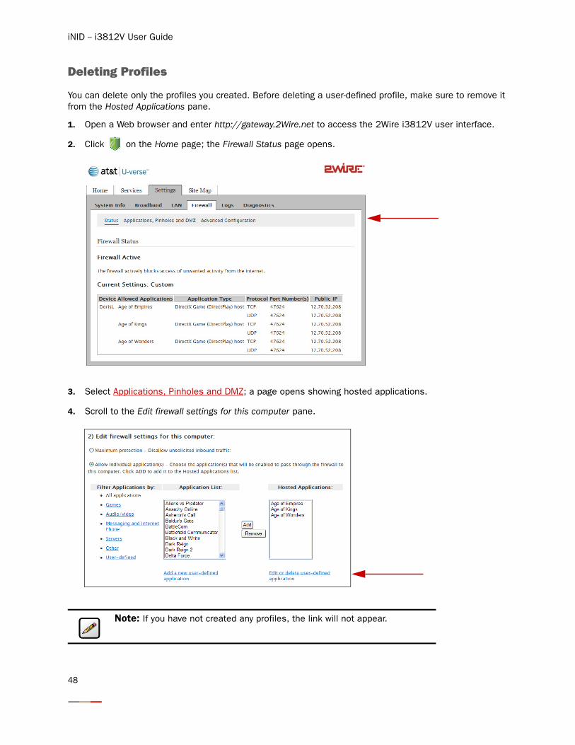
Deleting Profiles
You can delete only the profiles you created. Before deleting a user-defined profile, make sure to remove it from the Hosted Applications pane.
1. Open a Web browser and enter http://gateway.2Wire.net to access the 2Wire i3812V user interface.
2. Click on the Home page; the Firewall Status page opens.
3. Select Applications, Pinholes and DMZ; a page opens showing hosted applications.
4. Scroll to the Edit firewall settings for this computer pane.
Note: If you have not created any profiles, the link will not appear.
48
Configuring Firewall
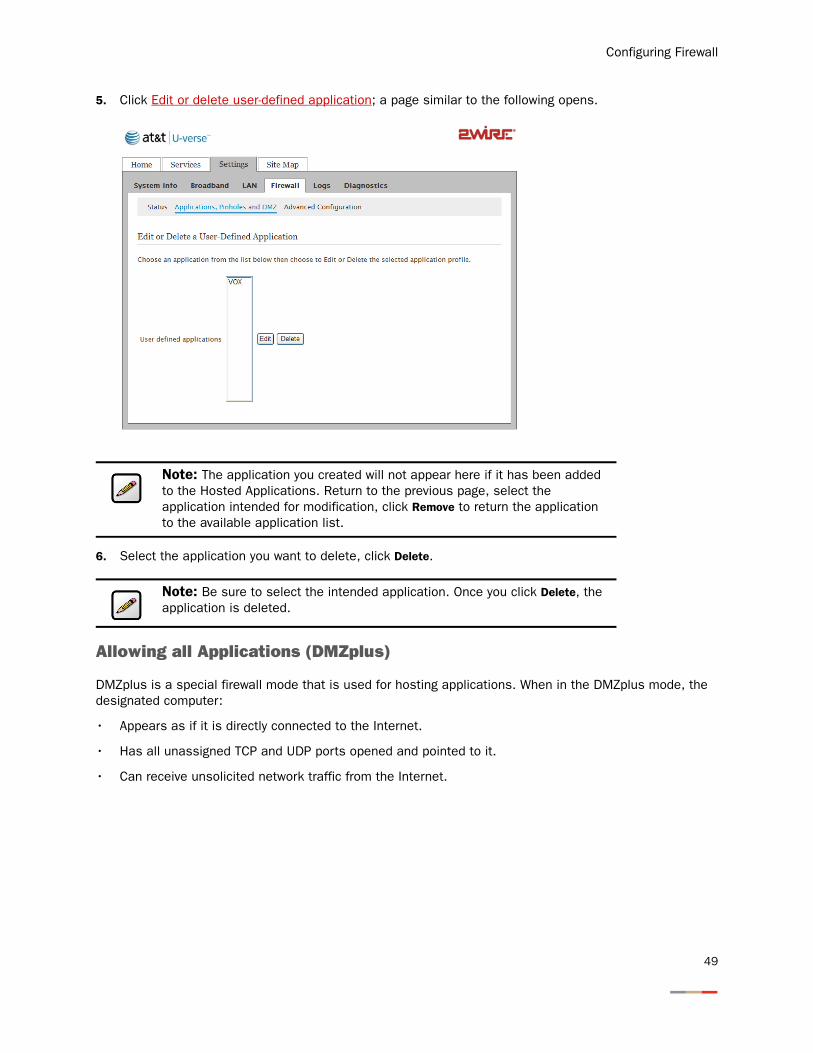
5. Click Edit or delete user-defined application; a page similar to the following opens.
6. Select the application you want to delete, click Delete.
Allowing all Applications (DMZplus)
DMZplus is a special firewall mode that is used for hosting applications. When in the DMZplus mode, the designated computer:
• Appears as if it is directly connected to the Internet.
• Has all unassigned TCP and UDP ports opened and pointed to it.
• Can receive unsolicited network traffic from the Internet.
Note: The application you created will not appear here if it has been added to the Hosted Applications. Return to the previous page, select the application intended for modification, click Remove to return the application to the available application list.
Note: Be sure to select the intended application. Once you click Delete, the application is deleted.
49
iNID -- i3812V User Guide
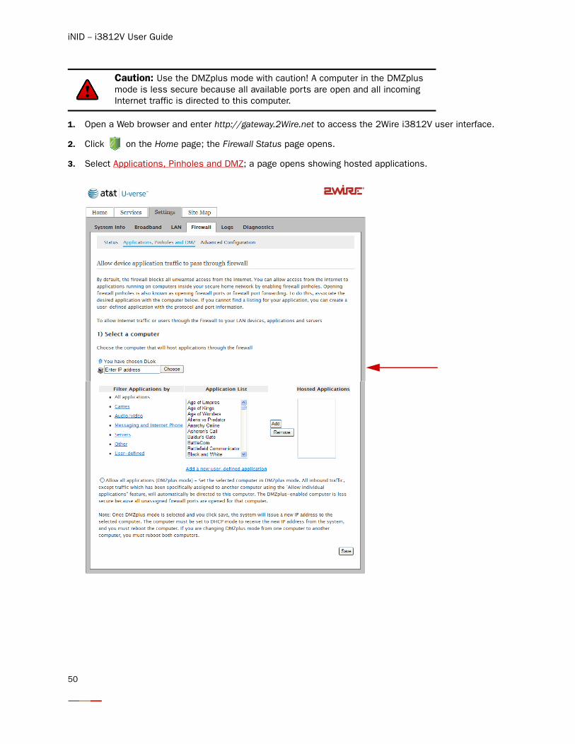
1. Open a Web browser and enter http://gateway.2Wire.net to access the 2Wire i3812V user interface.
2. Click on the Home page; the Firewall Status page opens.
3. Select Applications, Pinholes and DMZ; a page opens showing hosted applications.
Caution: Use the DMZplus mode with caution! A computer in the DMZplus mode is less secure because all available ports are open and all incoming Internet traffic is directed to this computer.
50
Configuring Firewall
4. Select the computer that you want to allow all applications.
5. Select the Allow all applications (DMZplus mode) button.
6. Click Save.
7. Confirm that the computer you selected in Step 1 is configured for DHCP. If it is not, configure it for DHCP.
8. Restart the computer. When the computer restarts, it receives a special IP address from the system and all unassigned TCP and UDP ports are forwarded to it.
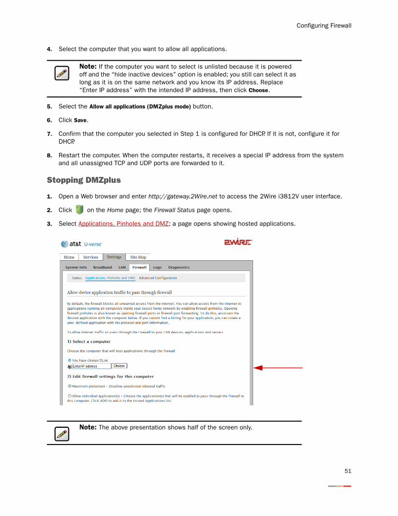
Stopping DMZplus
1. Open a Web browser and enter http://gateway.2Wire.net to access the 2Wire i3812V user interface.
2. Click on the Home page; the Firewall Status page opens.
3. Select Applications, Pinholes and DMZ; a page opens showing hosted applications.
Note: If the computer you want to select is unlisted because it is powered off and the “hide inactive devices” option is enabled; you still can select it as long as it is on the same network and you know its IP address. Replace “Enter IP address” with the intended IP address, then click Choose.
Note: The above presentation shows half of the screen only.
51
iNID -- i3812V User Guide
4. Select the computer that you want to stop the DMZplus mode.
5. Select the Maximum protection button from the Edit firewall settings for this computer pane.
6. Click Save.
7. Access the computer that you selected in Step 1.
8. Restart the computer.
Customizing Firewall Configuration
The i3812V comes with a set of default firewall settings that you can change to adapt to your environment. You can change the timeout sessions and protocol that you want to go through the firewall.
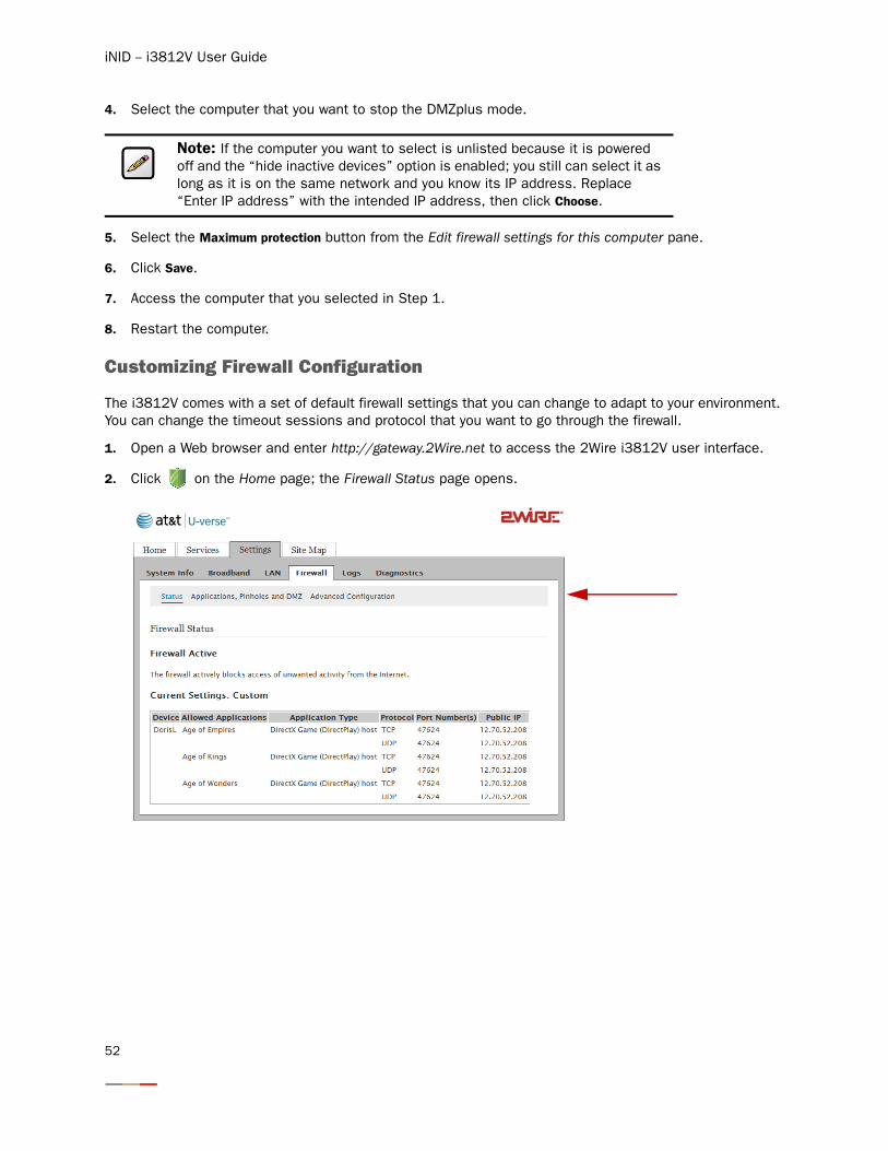
1. Open a Web browser and enter http://gateway.2Wire.net to access the 2Wire i3812V user interface.
2. Click on the Home page; the Firewall Status page opens.
Note: If the computer you want to select is unlisted because it is powered off and the “hide inactive devices” option is enabled; you still can select it as long as it is on the same network and you know its IP address. Replace “Enter IP address” with the intended IP address, then click Choose.
52
Configuring Firewall
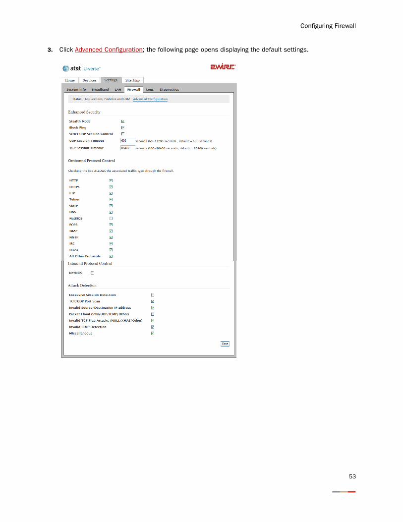
3. Click Advanced Configuration; the following page opens displaying the default settings.
53
iNID -- i3812V User Guide
4. Customize your Internet security.
− Stealth Mode: When the Stealth Mode is selected, your computer is “invisible” to port-scanning programs. Consequently, no reply is received in response in their quest to gain unauthorized access to computers and servers. If your computer is always connected to Internet, it is good practice to select the Stealth Mode to prevent potential hacking to your computer.
− Block Ping: When enabled, Block Ping blocks all ping requests. Ping is a basic Internet program that, when used without malicious intent, allows a user to verify that a particular IP address exists and can accept requests. Hackers can use ping to launch an attack against your network, because ping can determine the network’s IP address from the domain name.
− Strict UDP Session Control: Enabling this feature provides increased security by preventing the i3812V from accepting packets sent from an unknown source over an existing connection. The ability to send traffic based on destination only is required by some applications. Enabling this feature may not allow some on-line applications to work properly.
− UDP Session Timeout: Typically, the User Datagram Protocol (UDP) is used to exchange small data from one computer to another. Transmission Control Protocol (TCP) is used for larger data exchanges; therefore, the timeout setting for UDP is lower than that of TCP.
− TCP Session Timeout: Transmission Control Protocol (TCP) is a connection-oriented protocol, which means that a connection is established and maintained until such time as the message(s) to be exchanged by the application programs at each end have been exchanged. The maximum timeout is 24 hours.
5. Select the protocol(s) from the Outbound Control pane that you allow the traffic from the network to pass through the firewall to the Internet.
6. Select items from the Attack Detection pane to prevent unauthorized access to your computers.
− Excessive Session Detection: When enabled, the firewall detects applications on the local network that are creating excessive sessions out to the Internet. This activity is likely due to a virus or “worm” infected computer (for example, Blaster Worm).
− TCP/UDP Port Scan: A port scan is a series of messages sent by someone attempting to break into a computer to learn which computer network services, each associated with a well-known port number (such as UDP and TCP), the computer provides. When enabled, the firewall detects UDP and TCP port scans, and drops the packet.
Note: NetBIOS is primarily used for Local Area Network (LAN) communication. Typically, this protocol is not used on the Ethernet at large. For security reasons, it is blocked from the Internet to your local area network by default.
Note: These are stateless firewall checks and apply to DMZPlus or routed mode.
54
Configuring Firewall
− Invalid Source/Destination IP address. When enabled, the firewall checks and verifies the following IP addresses:
−IP source address (broadcast or multicast)
−TCP destination IP address (not unicast)
−If the IP source and destination address are the same
−Invalid IP source received from private/home network
− Packet Flood (SYN/UDP/ICMP/Other). When enabled, the firewall checks for SYN, UDP, ICMP, and other types of packet floods on the local and Internet-facing interfaces and stops the flood.
− Invalid TCP Flag Attacks (NULL/XMAS/Other). When enabled, the firewall scans inbound and outbound packets for invalid TCP flag settings, and drops the packet to prevent SYN/FIN, NULL, and XMAS attacks.
− Invalid ICMP Detection. The firewall checks for invalid ICMP/code types, and drops the packets.
− Miscellaneous. The firewall checks for the following, and drops the packets or terminates the associated session:
−Unknown IP protocol (drop packet)
−Port 0 attack detected (drop packet)
−TCP SYN packet (drop packet)
−Not a start session packet (drop packet)
−ICMP destination unreachable (terminate session)
7. Click Save; a message appears informing you of the operational status.
Note: The packets are dropped when IP addresses cannot be verified.
55

iNID -- i3812V User Guide
56

Working with the Power Supply Unit
The iPSU needs no scheduled maintenance other than regular battery inspection and replacement. If the power supply unit is equipped with a backup battery, it continues to provide voice-over-IP services in case of emergency during a power outage. During a temporary AC power outage, the power source is switched to the battery without interruption of the voice-over-IP service. When the AC power is restored, the power source is switched back to the power supply unit. The switchover between the power supply unit and the battery is automatic and instantaneous.
This section provides instructions to:
• Replace the battery on page 58
• Disable the audio alert on page 61
• Enable the audio alert on page 63
Note: Reserve the battery charge during a power outage. Do not access the Internet when the power is running on the battery. Doing so will discharge the battery at a much faster rate and shorten the voice-over-IP service time.
Note: You are solely responsible for periodically replacing this battery to provide uninterruptable voice-over-IP services during a power outage. Your service provide does not monitor the battery and is not responsible for its replacement.
57

iNID -- i3812V User Guide
Replacing the Battery
The battery is rated for a service life of up to five years, which varies depending on operational and environmental conditions. The battery life expectancy depends on the operating environment as temperature extremes shorten the battery life. The optimum operating temperature is between –5o C to +50o C, ambient (23.0o F to 122o F).
The battery is specifically designed to use with the iNID system. Contact your service provider for battery replacement information.
To replace the battery:
1. Use a Phillips screwdriver to unfasten two screws (one on each side) securing the power supply battery cover, and put them in a safe place (Figure 11).
Figure 11: Power Supply Unit Cover Removal
2. Bring the battery cable and battery cable connector to visibility (located on top of the backup battery).
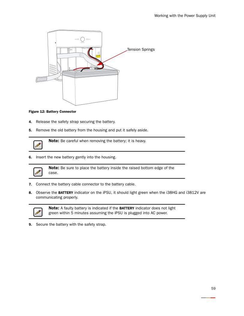
3. Press down on the tension springs and pull to disconnect the battery cable connector from the battery cable (Figure 12).
Remove screws from both sides ofthe unit to remove the front cover.
58
Working with the Power Supply Unit
Figure 12: Battery Connector
4. Release the safety strap securing the battery.
5. Remove the old battery from the housing and put it safely aside.
6. Insert the new battery gently into the housing.
7. Connect the battery cable connector to the battery cable.
8. Observe the BATTERY indicator on the iPSU, it should light green when the i38HG and i3812V are communicating properly.
9. Secure the battery with the safety strap.
Note: Be careful when removing the battery; it is heavy.
Note: Be sure to place the battery inside the raised bottom edge of the case.
Note: A faulty battery is indicated if the BATTERY indicator does not light green within 5 minutes assuming the iPSU is plugged into AC power.
POWER
SILENCE ALARM
BATTERY
CAUTIONPOTENTIAL SHOCK
Tension Springs
59
iNID -- i3812V User Guide
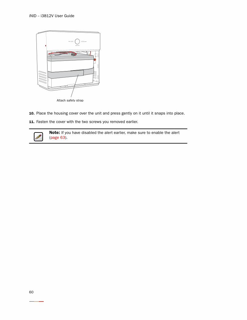
10. Place the housing cover over the unit and press gently on it until it snaps into place.
11. Fasten the cover with the two screws you removed earlier.
Note: If you have disabled the alert earlier, make sure to enable the alert (page 63).
60
Working with the Power Supply Unit
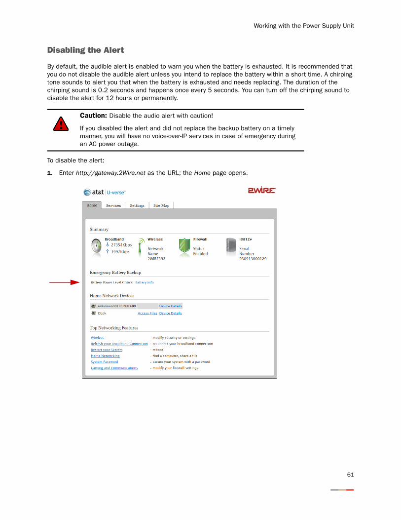
Disabling the Alert
By default, the audible alert is enabled to warn you when the battery is exhausted. It is recommended that you do not disable the audible alert unless you intend to replace the battery within a short time. A chirping tone sounds to alert you that when the battery is exhausted and needs replacing. The duration of the chirping sound is 0.2 seconds and happens once every 5 seconds. You can turn off the chirping sound to disable the alert for 12 hours or permanently.
To disable the alert:
1. Enter http://gateway.2Wire.net as the URL; the Home page opens.
Caution: Disable the audio alert with caution!
If you disabled the alert and did not replace the backup battery on a timely manner, you will have no voice-over-IP services in case of emergency during an AC power outage.
61
iNID -- i3812V User Guide
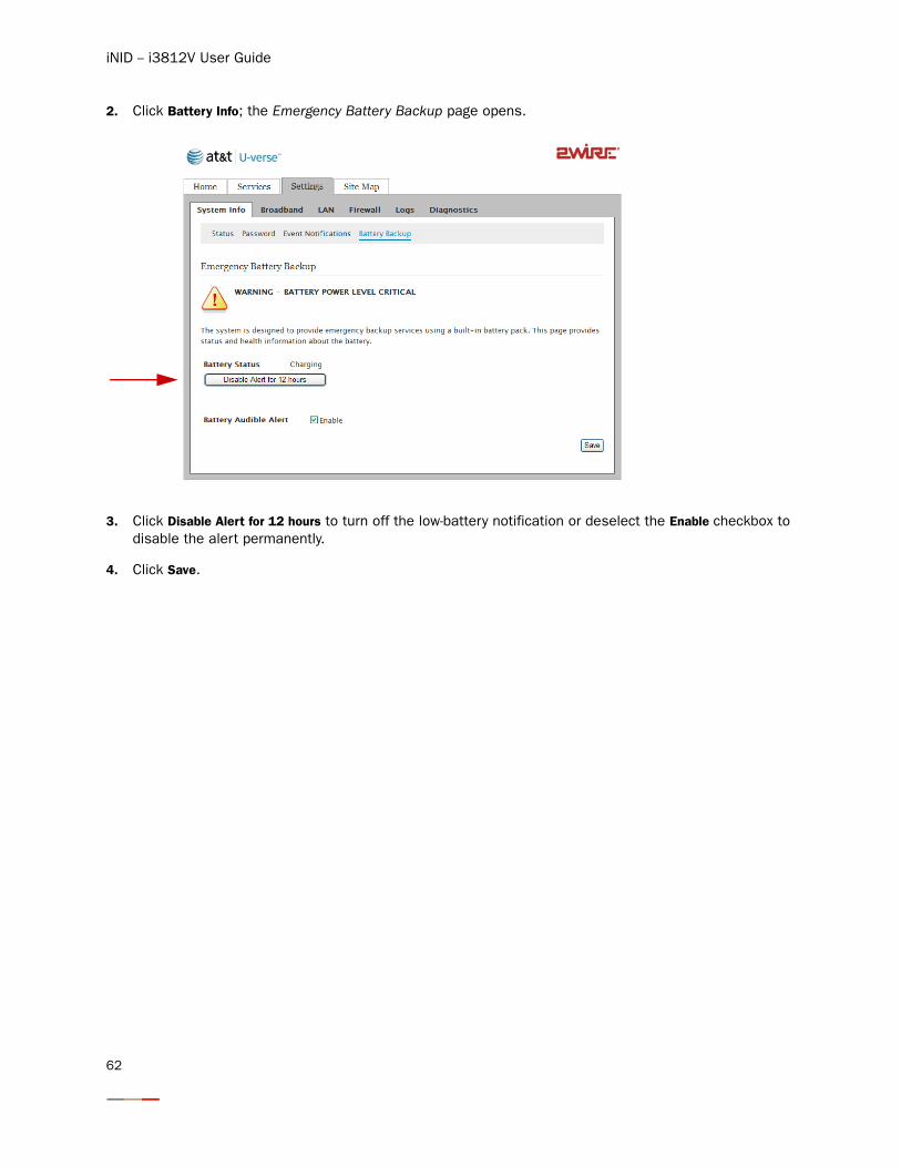
2. Click Battery Info; the Emergency Battery Backup page opens.
3. Click Disable Alert for 12 hours to turn off the low-battery notification or deselect the Enable checkbox to disable the alert permanently.
4. Click Save.
62
Working with the Power Supply Unit
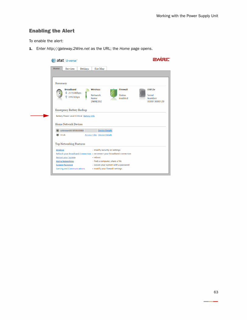
Enabling the Alert
To enable the alert:
1. Enter http://gateway.2Wire.net as the URL; the Home page opens.
63
iNID -- i3812V User Guide
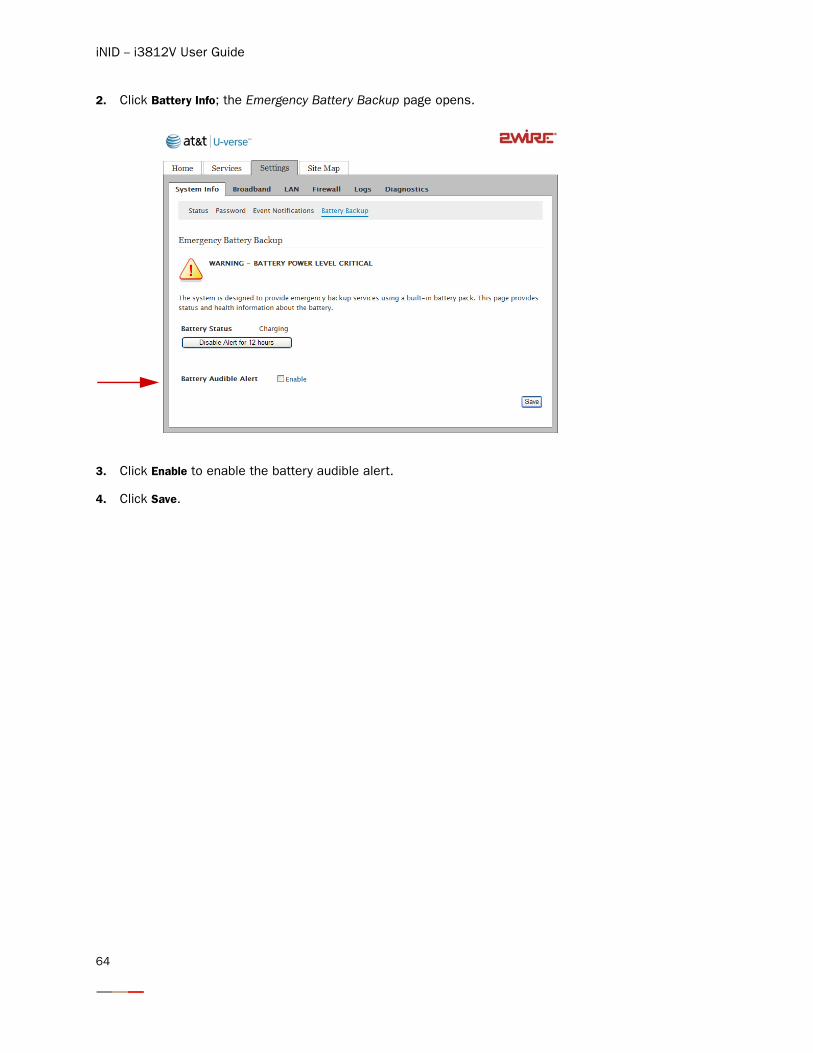
2. Click Battery Info; the Emergency Battery Backup page opens.
3. Click Enable to enable the battery audible alert.
4. Click Save.
64
Configuring Services
There is no user-configuration needed for VoIP service. All server and line configuration are performed by your service provider. Refer to Table 5 in the Finding Solutions section if you encounter VoIP services related issues.
This section provides instructions to:
• Set up Access control on page 66
• Configure Content screening on page 69
• Configure Web remote access on page 74
• Access local network with Web remote access on page 76
65
iNID -- i3812V User Guide
Setting up Access Control
The access control feature enables you to set restrictions on content access and time-of-day access for any device connected to your gateway. Access control can be set up for Web browsing, instant messaging, and other applications.
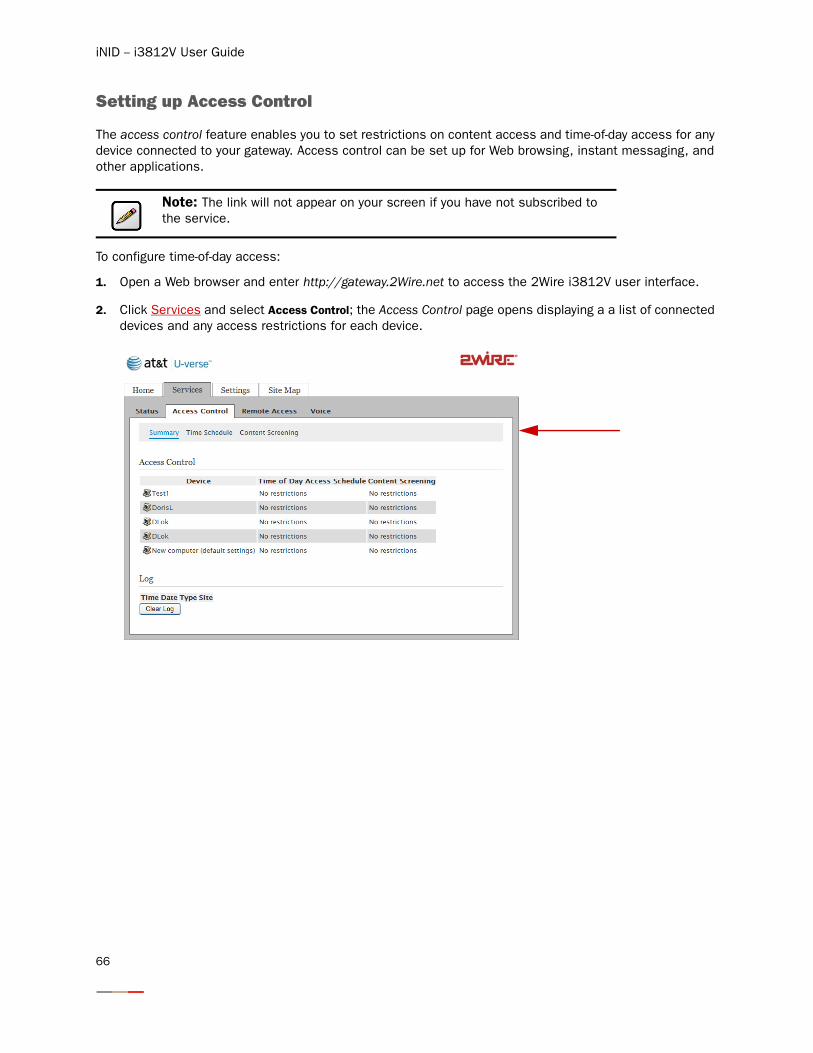
To configure time-of-day access:
1. Open a Web browser and enter http://gateway.2Wire.net to access the 2Wire i3812V user interface.
2. Click Services and select Access Control; the Access Control page opens displaying a a list of connected devices and any access restrictions for each device.
Note: The link will not appear on your screen if you have not subscribed to the service.
66
Configuring Services
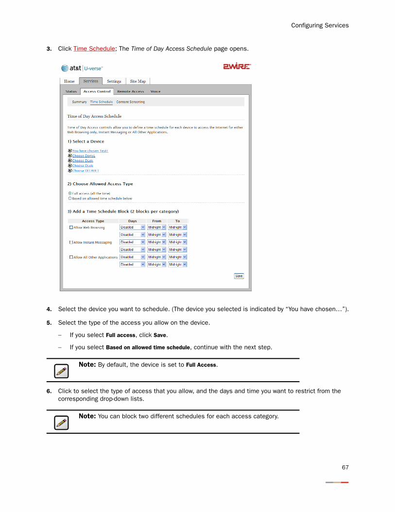
3. Click Time Schedule; The Time of Day Access Schedule page opens.
4. Select the device you want to schedule. (The device you selected is indicated by “You have chosen…”).
5. Select the type of the access you allow on the device.
− If you select Full access, click Save.
− If you select Based on allowed time schedule, continue with the next step.
6. Click to select the type of access that you allow, and the days and time you want to restrict from the corresponding drop-down lists.
Note: By default, the device is set to Full Access.
Note: You can block two different schedules for each access category.
67
iNID -- i3812V User Guide
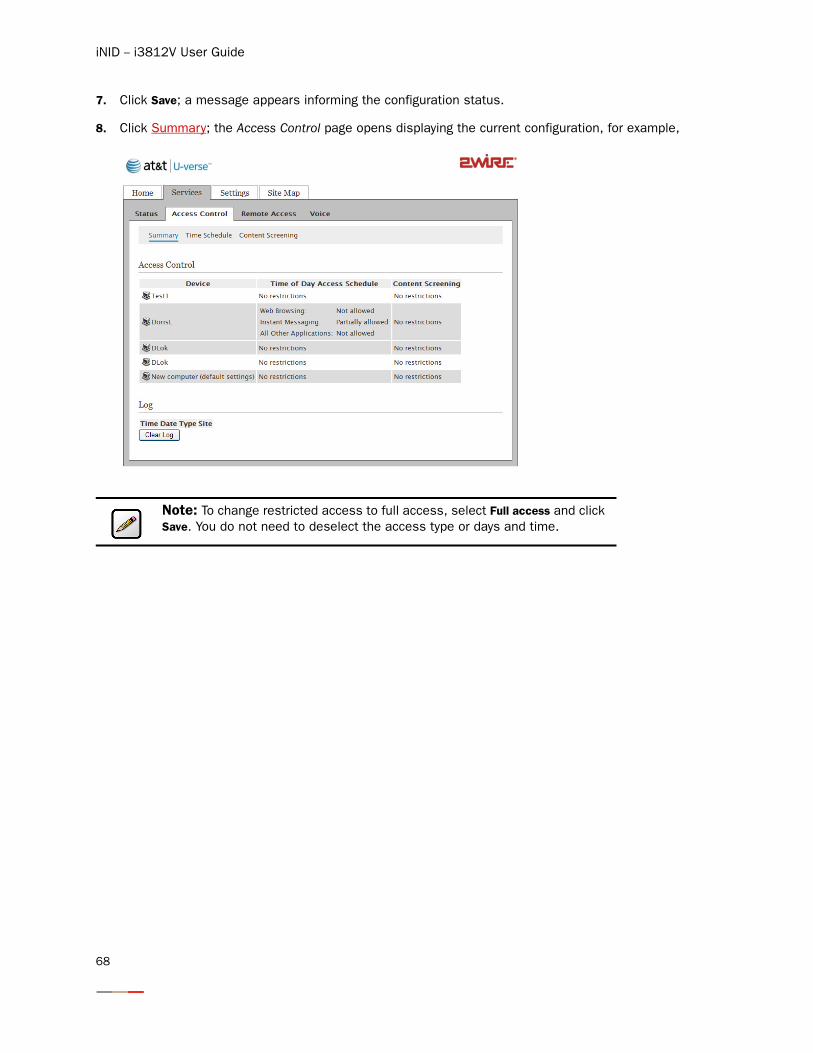
7. Click Save; a message appears informing the configuration status.
8. Click Summary; the Access Control page opens displaying the current configuration, for example,
Note: To change restricted access to full access, select Full access and click Save. You do not need to deselect the access type or days and time.
68
Configuring Services
Configuring Content Screening
The content screening feature enables you to block specific computers from being able to view objectionable material online. You can customize the content screening for two separate groups: Kids and Teens. Configuring content screening requires these sequential tasks:
• Assign a computer to a group on page 69
• Set restrictions on groups on page 70
• Specify Web sites on page 72
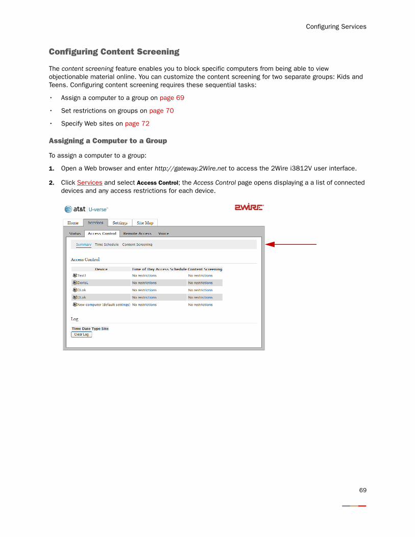
Assigning a Computer to a Group
To assign a computer to a group:
1. Open a Web browser and enter http://gateway.2Wire.net to access the 2Wire i3812V user interface.
2. Click Services and select Access Control; the Access Control page opens displaying a a list of connected devices and any access restrictions for each device.
69
iNID -- i3812V User Guide
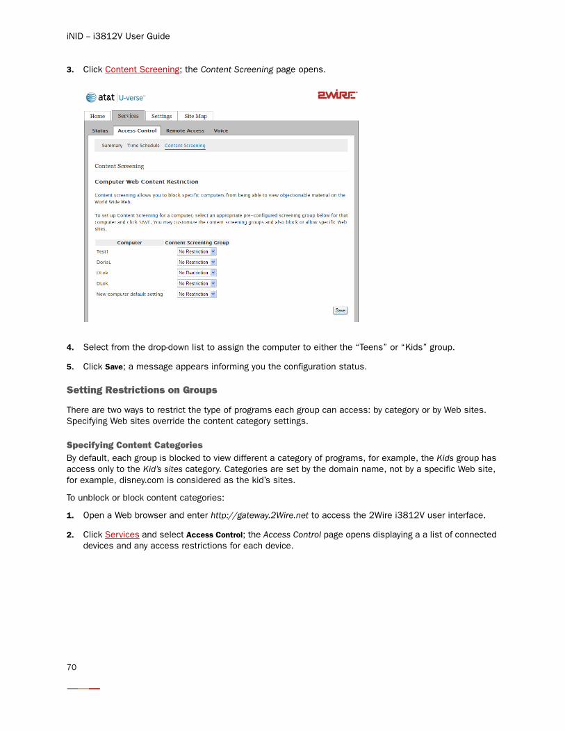
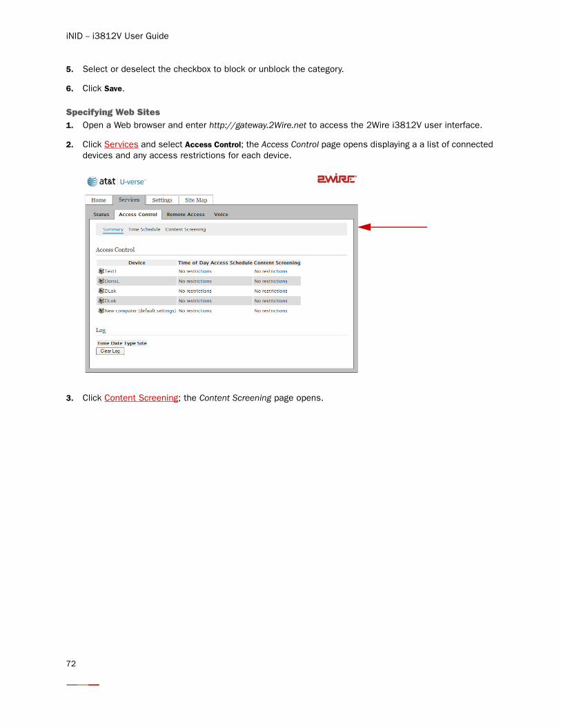
3. Click Content Screening; the Content Screening page opens.
4. Select from the drop-down list to assign the computer to either the “Teens” or “Kids” group.
5. Click Save; a message appears informing you the configuration status.
Setting Restrictions on Groups
There are two ways to restrict the type of programs each group can access: by category or by Web sites. Specifying Web sites override the content category settings.
Specifying Content CategoriesBy default, each group is blocked to view different a category of programs, for example, the Kids group has access only to the Kid’s sites category. Categories are set by the domain name, not by a specific Web site, for example, disney.com is considered as the kid’s sites.
To unblock or block content categories:
1. Open a Web browser and enter http://gateway.2Wire.net to access the 2Wire i3812V user interface.
2. Click Services and select Access Control; the Access Control page opens displaying a a list of connected devices and any access restrictions for each device.
70
Configuring Services
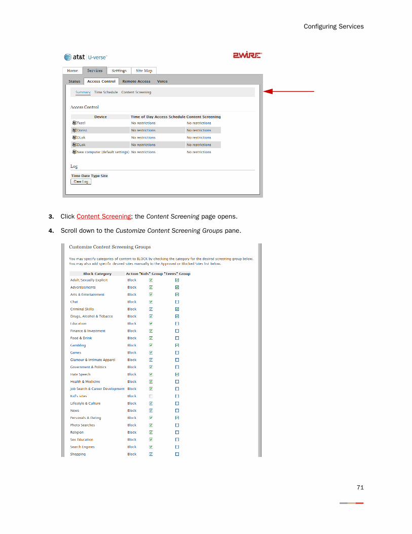
3. Click Content Screening; the Content Screening page opens.
4. Scroll down to the Customize Content Screening Groups pane.
71
iNID -- i3812V User Guide
5. Select or deselect the checkbox to block or unblock the category.
6. Click Save.
Specifying Web Sites 1. Open a Web browser and enter http://gateway.2Wire.net to access the 2Wire i3812V user interface.
2. Click Services and select Access Control; the Access Control page opens displaying a a list of connected devices and any access restrictions for each device.
3. Click Content Screening; the Content Screening page opens.
72
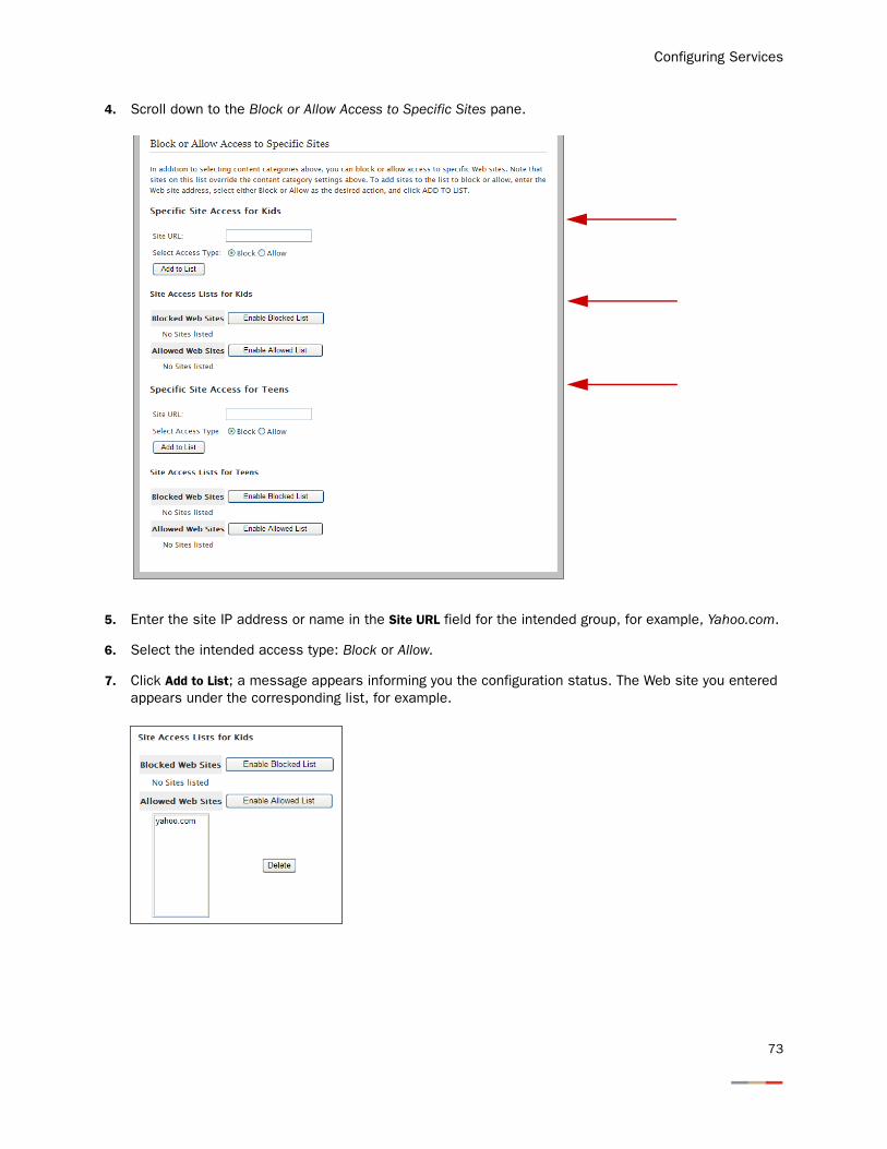
Configuring Services
4. Scroll down to the Block or Allow Access to Specific Sites pane.
5. Enter the site IP address or name in the Site URL field for the intended group, for example, Yahoo.com.
6. Select the intended access type: Block or Allow.
7. Click Add to List; a message appears informing you the configuration status. The Web site you entered appears under the corresponding list, for example.
73
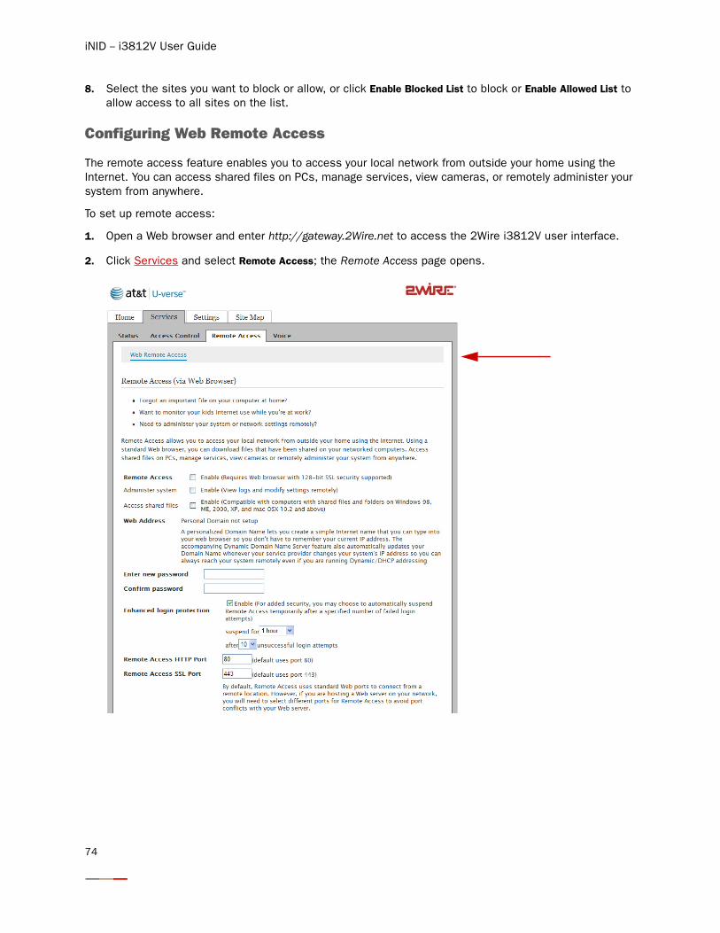
iNID -- i3812V User Guide
8. Select the sites you want to block or allow, or click Enable Blocked List to block or Enable Allowed List to allow access to all sites on the list.
Configuring Web Remote Access
The remote access feature enables you to access your local network from outside your home using the Internet. You can access shared files on PCs, manage services, view cameras, or remotely administer your system from anywhere.
To set up remote access:
1. Open a Web browser and enter http://gateway.2Wire.net to access the 2Wire i3812V user interface.
2. Click Services and select Remote Access; the Remote Access page opens.
74
Configuring Services
3. Select the Remote Access checkbox to enable the remote access feature.
4. Select the Access shared files checkbox if you want to enable the shared files feature.
5. Click Edit Domain Name to enter your domain name that you will need to enter
6. Enter a password containing at least eight alphanumeric characters in the Enter new password field.
7. Confirm your password in the corresponding field.
8. Select the Enhanced login protection checkbox to prevent repeated “guessing” of the Web Remote Access password.
9. Select from the corresponding drop-down lists to temporarily suspend remote access after a number of failed login attempts.
10. Change the default HTTP and SSL ports if you are hosting a Web server on your network to avoid port conflicts with your Web server.
11. Click Save.
Note: You will need to enter this domain name into a Web browser when you access your system remotely.
Note: You will need to enter this password when you access your system remotely.
Note: It is recommended to leave the added security value as enabled (the default value).
75
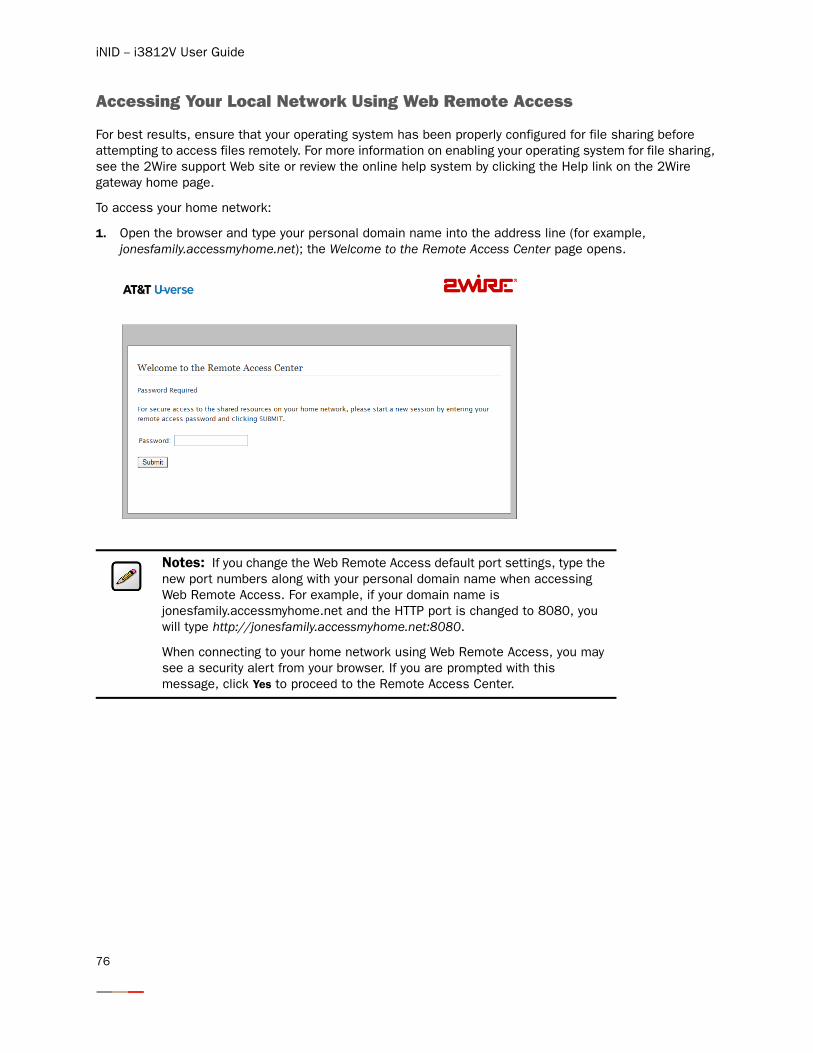
iNID -- i3812V User Guide
Accessing Your Local Network Using Web Remote Access
For best results, ensure that your operating system has been properly configured for file sharing before attempting to access files remotely. For more information on enabling your operating system for file sharing, see the 2Wire support Web site or review the online help system by clicking the Help link on the 2Wire gateway home page.
To access your home network:
1. Open the browser and type your personal domain name into the address line (for example, jonesfamily.accessmyhome.net); the Welcome to the Remote Access Center page opens.
Notes: If you change the Web Remote Access default port settings, type the new port numbers along with your personal domain name when accessing Web Remote Access. For example, if your domain name is jonesfamily.accessmyhome.net and the HTTP port is changed to 8080, you will type http://jonesfamily.accessmyhome.net:8080.
When connecting to your home network using Web Remote Access, you may see a security alert from your browser. If you are prompted with this message, click Yes to proceed to the Remote Access Center.
76
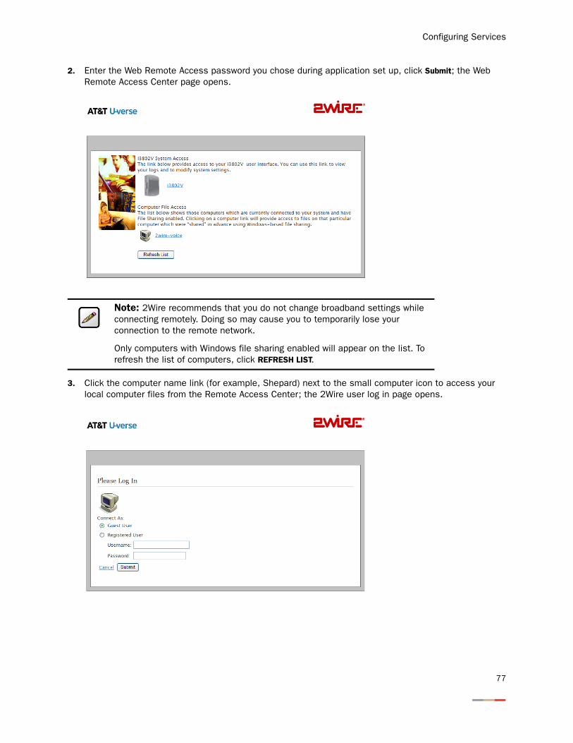
Configuring Services
2. Enter the Web Remote Access password you chose during application set up, click Submit; the Web Remote Access Center page opens.
3. Click the computer name link (for example, Shepard) next to the small computer icon to access your local computer files from the Remote Access Center; the 2Wire user log in page opens.
Note: 2Wire recommends that you do not change broadband settings while connecting remotely. Doing so may cause you to temporarily lose your connection to the remote network.
Only computers with Windows file sharing enabled will appear on the list. To refresh the list of computers, click REFRESH LIST.
77
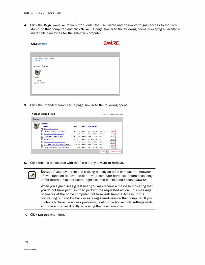
iNID -- i3812V User Guide
4. Click the Registered User radio button, enter the user name and password to gain access to the files stored on that computer, and click Submit. A page similar to the following opens displaying all available shared file directories for the selected computer.
5. Click the intended computer; a page similar to the following opens.
6. Click the link associated with the file name you want to retrieve.
7. Click Log Out when done.
Notes: If you have problems clicking directly on a file link, use the browser “Save” function to save the file to your computer hard disk before accessing it. For Internet Explorer users, right-click the file link and choose Save As.
When you signed in as guest user, you may receive a message indicating that you do not have permission to perform the requested action. This message originates at the home computer, not from Web Remote Access. If this occurs, log out and log back in as a registered user on that computer. If you continue to have file access problems, confirm the file security settings while at home and when directly accessing the local computer.
78
Configuring LAN Devices
Typically, your Internet service provider automatically assigns and configures a dynamic IP address when your system connects to the Internet. Businesses or power users may use a static address enabling them to run advanced services such as Internet servers and video conferences. The availability of static IP addresses is usually an additional service offered by service providers. In addition, changes from the default behavior of the gateway for private IP addressing may also be used by some users.
Configure these settings ONLY if you are very familiar with computer networking technologies. This section provides instructions to set up your private network that includes:
• Configuring additional network on page 80
• Configuring DHCP on page 81
• Allocating IP addresses on page 85
• Selecting DSL lines on page 88
79
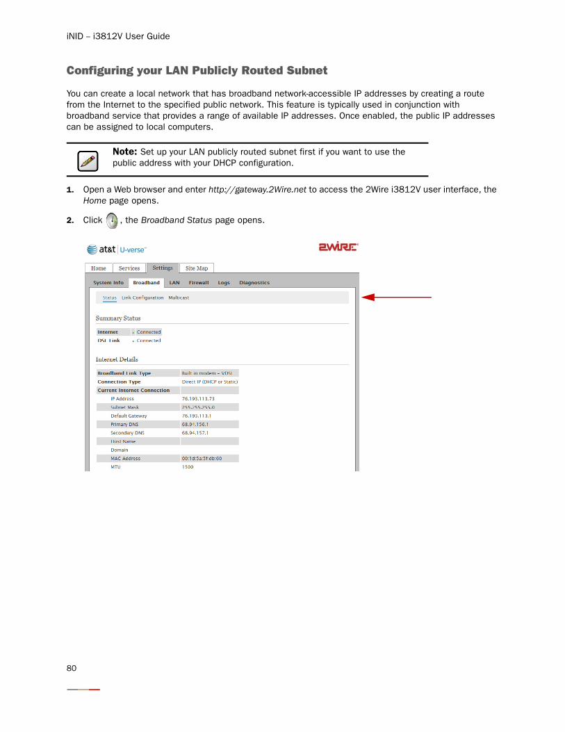
iNID -- i3812V User Guide
Configuring your LAN Publicly Routed Subnet
You can create a local network that has broadband network-accessible IP addresses by creating a route from the Internet to the specified public network. This feature is typically used in conjunction with broadband service that provides a range of available IP addresses. Once enabled, the public IP addresses can be assigned to local computers.
1. Open a Web browser and enter http://gateway.2Wire.net to access the 2Wire i3812V user interface, the Home page opens.
2. Click , the Broadband Status page opens.
Note: Set up your LAN publicly routed subnet first if you want to use the public address with your DHCP configuration.
80
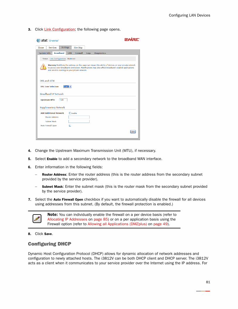
Configuring LAN Devices
3. Click Link Configuration; the following page opens.
4. Change the Upstream Maximum Transmission Unit (MTU), if necessary.
5. Select Enable to add a secondary network to the broadband WAN interface.
6. Enter information in the following fields:
− Router Address: Enter the router address (this is the router address from the secondary subnet provided by the service provider).
− Subnet Mask: Enter the subnet mask (this is the router mask from the secondary subnet provided by the service provider).
7. Select the Auto Firewall Open checkbox if you want to automatically disable the firewall for all devices using addresses from this subnet. (By default, the firewall protection is enabled.)
8. Click Save.
Configuring DHCP
Dynamic Host Configuration Protocol (DHCP) allows for dynamic allocation of network addresses and configuration to newly attached hosts. The i3812V can be both DHCP client and DHCP server. The i3812V acts as a client when it communicates to your service provider over the Internet using the IP address. For
Note: You can individually enable the firewall on a per device basis (refer to Allocating IP Addresses on page 85) or on a per application basis using the Firewall option (refer to Allowing all Applications (DMZplus) on page 49).
81
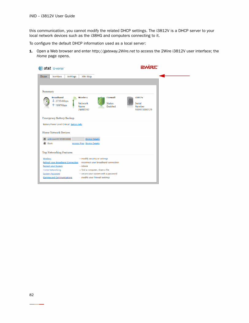
iNID -- i3812V User Guide
this communication, you cannot modify the related DHCP settings. The i3812V is a DHCP server to your local network devices such as the i38HG and computers connecting to it.
To configure the default DHCP information used as a local server:
1. Open a Web browser and enter http://gateway.2Wire.net to access the 2Wire i3812V user interface; the Home page opens.
82
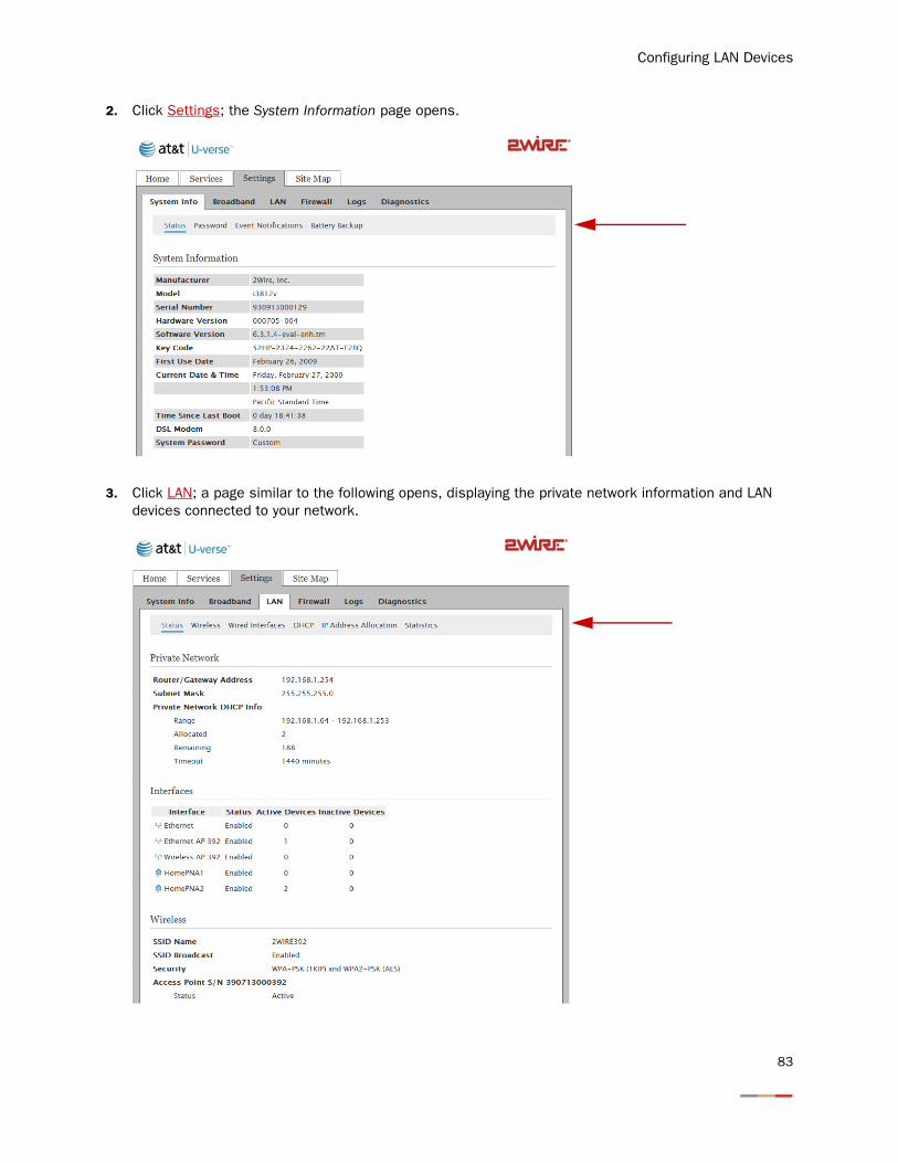
Configuring LAN Devices
2. Click Settings; the System Information page opens.
3. Click LAN; a page similar to the following opens, displaying the private network information and LAN devices connected to your network.
83
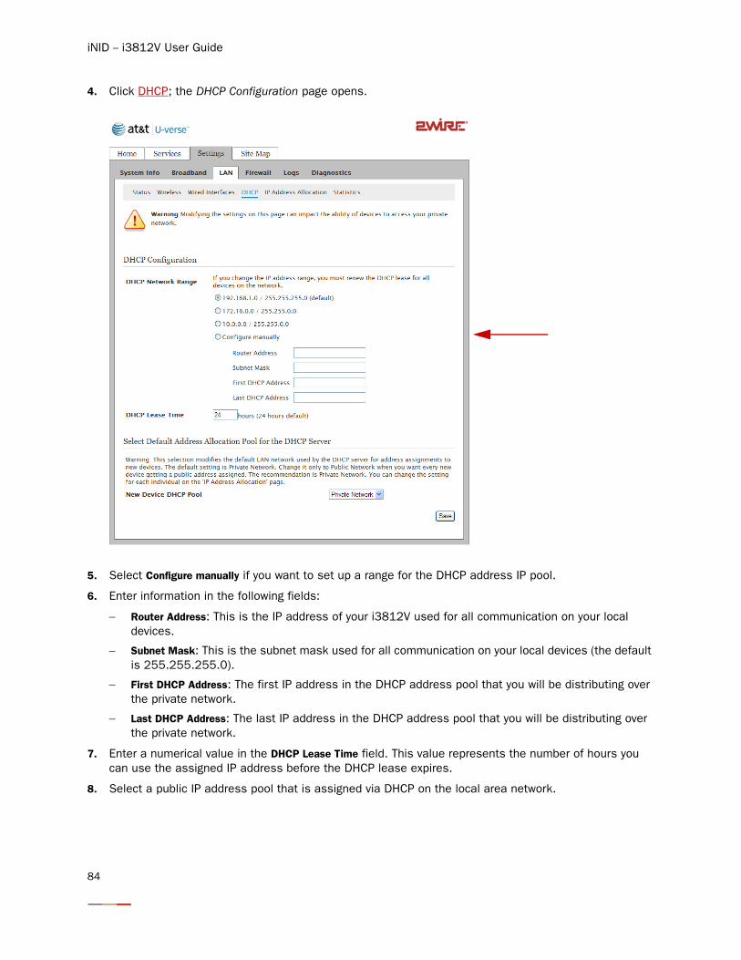
iNID -- i3812V User Guide
4. Click DHCP; the DHCP Configuration page opens.
5. Select Configure manually if you want to set up a range for the DHCP address IP pool.
6. Enter information in the following fields:
− Router Address: This is the IP address of your i3812V used for all communication on your local devices.
− Subnet Mask: This is the subnet mask used for all communication on your local devices (the default is 255.255.255.0).
− First DHCP Address: The first IP address in the DHCP address pool that you will be distributing over the private network.
− Last DHCP Address: The last IP address in the DHCP address pool that you will be distributing over the private network.
7. Enter a numerical value in the DHCP Lease Time field. This value represents the number of hours you can use the assigned IP address before the DHCP lease expires.
8. Select a public IP address pool that is assigned via DHCP on the local area network.
84
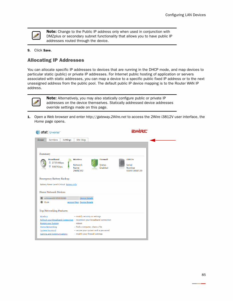
Configuring LAN Devices
9. Click Save.
Allocating IP Addresses
You can allocate specific IP addresses to devices that are running in the DHCP mode, and map devices to particular static (public) or private IP addresses. For Internet public hosting of application or servers associated with static addresses, you can map a device to a specific public fixed IP address or to the next unassigned address from the public pool. The default public IP device mapping is to the Router WAN IP address.
1. Open a Web browser and enter http://gateway.2Wire.net to access the 2Wire i3812V user interface, the Home page opens.
Note: Change to the Public IP address only when used in conjunction with DMZplus or secondary subnet functionality that allows you to have public IP addresses routed through the device.
Note: Alternatively, you may also statically configure public or private IP addresses on the device themselves. Statically addressed device addresses override settings made on this page.
85
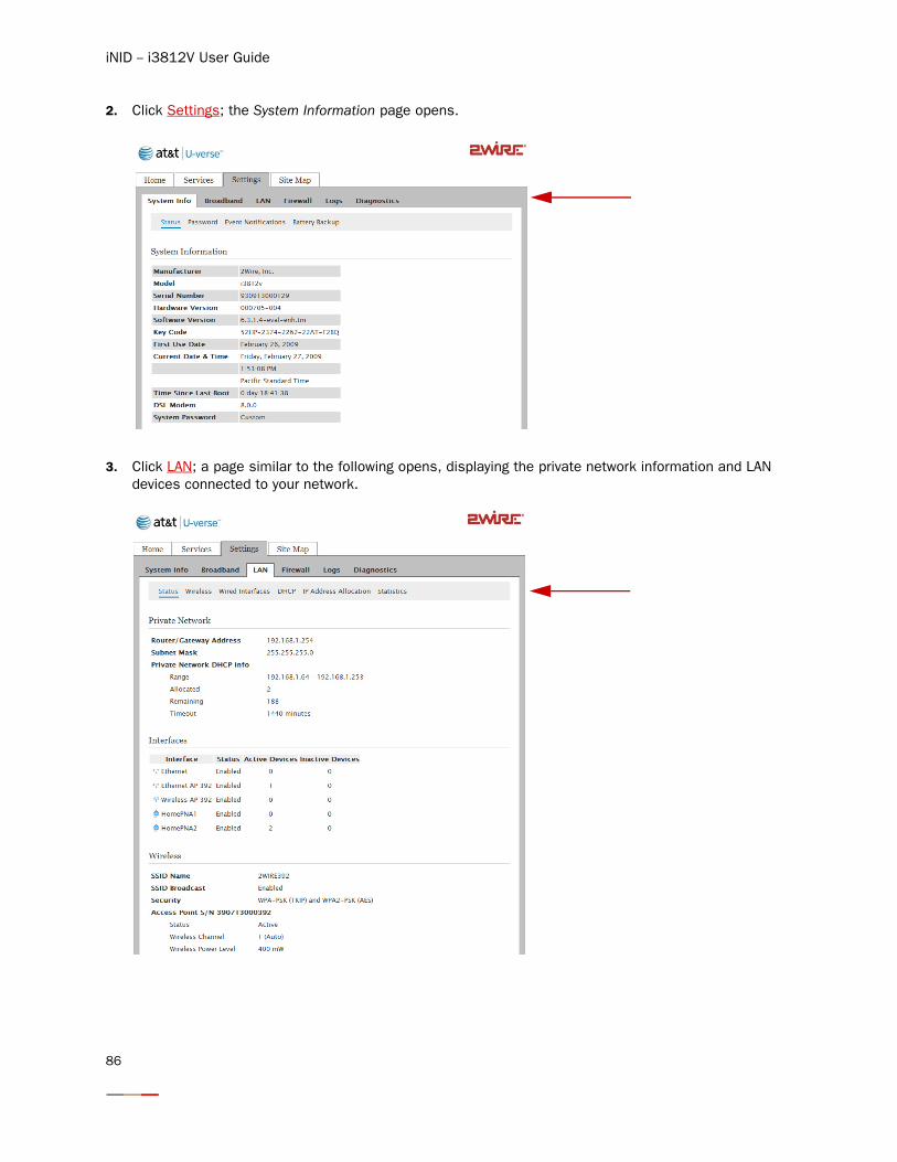
iNID -- i3812V User Guide
2. Click Settings; the System Information page opens.
3. Click LAN; a page similar to the following opens, displaying the private network information and LAN devices connected to your network.
86
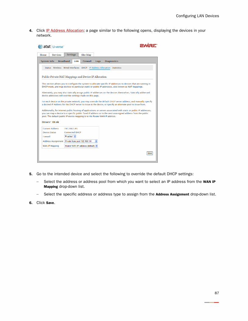
Configuring LAN Devices
4. Click IP Address Allocation; a page similar to the following opens, displaying the devices in your network.
5. Go to the intended device and select the following to override the default DHCP settings:
− Select the address or address pool from which you want to select an IP address from the WAN IP Mapping drop-down list.
− Select the specific address or address type to assign from the Address Assignment drop-down list.
6. Click Save.
87
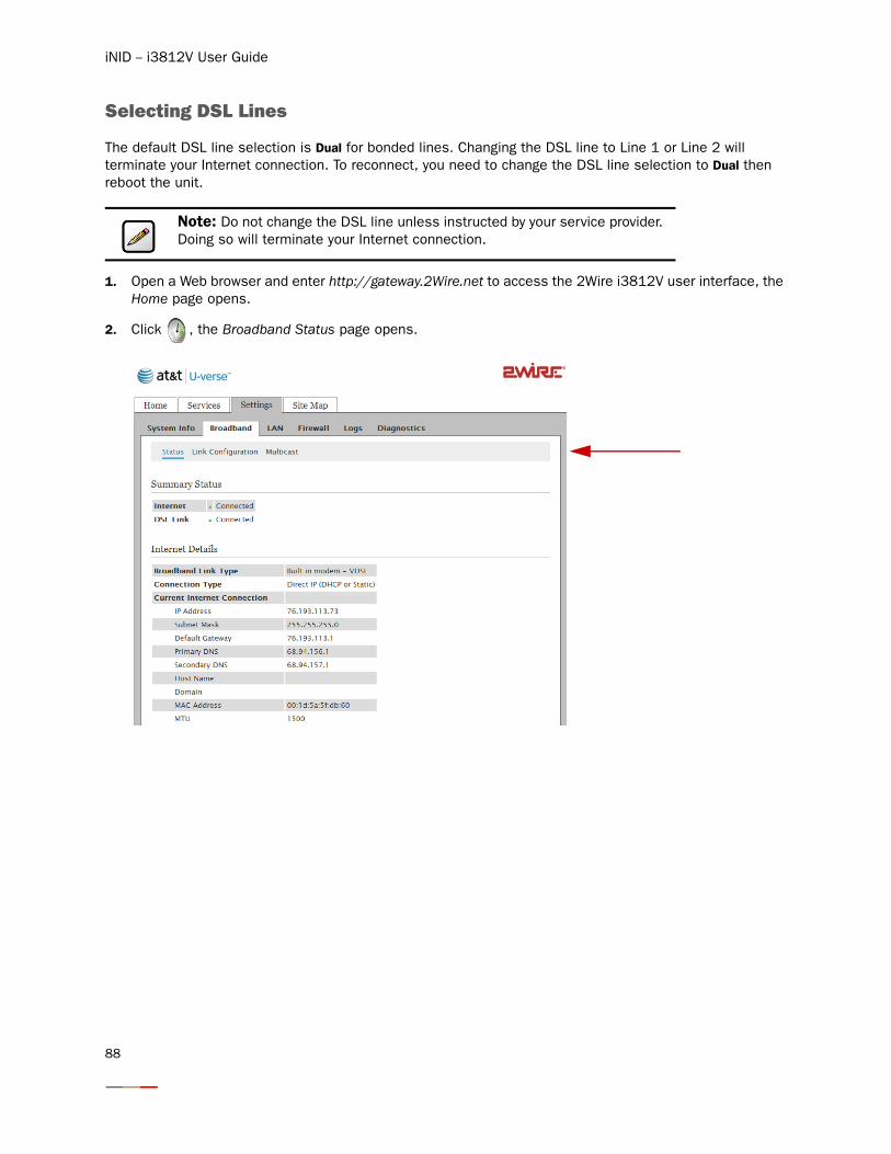
iNID -- i3812V User Guide
Selecting DSL Lines
The default DSL line selection is Dual for bonded lines. Changing the DSL line to Line 1 or Line 2 will terminate your Internet connection. To reconnect, you need to change the DSL line selection to Dual then reboot the unit.
1. Open a Web browser and enter http://gateway.2Wire.net to access the 2Wire i3812V user interface, the Home page opens.
2. Click , the Broadband Status page opens.
Note: Do not change the DSL line unless instructed by your service provider. Doing so will terminate your Internet connection.
88
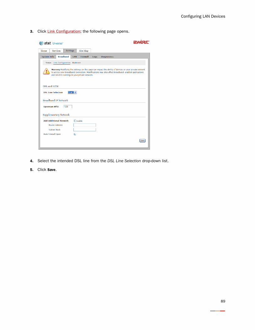
Configuring LAN Devices
3. Click Link Configuration; the following page opens.
4. Select the intended DSL line from the DSL Line Selection drop-down list.
5. Click Save.
89

iNID -- i3812V User Guide
90
Finding Solutions
The i3812V comes with diagnostics tools, such as link test, DSL, IP PING, trace route, DNS query, and so forth. This section provides helpful information to solve common issues. It also provides instructions to view various statistics and logs.
• Connection issues on page 92
• VoIP issues on page 94
• iPSU issues on page 95
• System issues on page 95
• DSL bandwidths information on page 96
• Voice service information on page 98
• Wireless AP statistics on page 101
• LAN status on page 102
• HPNA performance tests on page 105
• HPNA COAX and phones statistics on page 111
• Logs on page 114
91
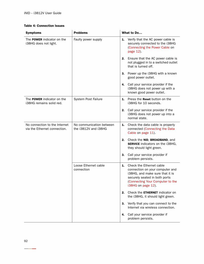
iNID -- i3812V User Guide
Table 4: Connection Issues
Symptoms Problems What to Do…
The POWER indicator on the i38HG does not light.
Faulty power supply 1. Verify that the AC power cable is securely connected to the i38HG (Connecting the Power Cable on page 12).
2. Ensure that the AC power cable is not plugged in to a switched outlet that is turned off.
3. Power up the i38HG with a known good power outlet.
4. Call your service provider if the i38HG does not power up with a known good power outlet.
The POWER indicator on the i38HG remains solid red.
System Post Failure 1. Press the Reset button on the i38HG for 10 seconds.
2. Call your service provider if the i38HG does not power up into a normal state.
No connection to the Internet via the Ethernet connection.
No communication between the i3812V and i38HG
1. Check the data cable is properly connected (Connecting the Data Cable on page 11).
2. Check the NID, BROADBAND, and SERVICE indicators on the i38HG, they should light green.
3. Call your service provider if problem persists.
Loose Ethernet cable connection
1. Check the Ethernet cable connection on your computer and i38HG, and make sure that it is securely seated in both ports (Connecting Your Computer to the i38HG on page 12).
2. Check the ETHERNET indicator on the i38HG, it should light green.
3. Verify that you can connect to the Internet via wireless connection.
4. Call your service provider if problem persists.
92
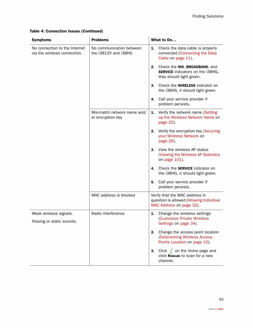
Finding Solutions
No connection to the Internet via the wireless connection.
No communication between the i3812V and i38HG
1. Check the data cable is properly connected (Connecting the Data Cable on page 11).
2. Check the NID, BROADBAND, and SERVICE indicators on the i38HG, they should light green.
3. Check the WIRELESS indicator on the i38HG, it should light green.
4. Call your service provider if problem persists.
Mis-match network name and/or encryption key
1. Verify the network name (Setting up the Wireless Network Name on page 25).
2. Verify the encryption key (Securing your Wireless Network on page 26).
3. View the wireless AP status (Viewing the Wireless AP Statistics on page 101).
4. Check the SERVICE indicator on the i38HG, it should light green.
5. Call your service provider if problem persists.
MAC address is blocked Verify that the MAC address in question is allowed (Allowing Individual MAC Address on page 32).
Weak wireless signals.
Hissing or static sounds.
Radio interference 1. Change the wireless settings (Customize Private Wireless Settings on page 34).
2. Change the access point location (Determining Wireless Access Points Location on page 10).
3. Click on the Home page and click Rescan to scan for a new channel.
Table 4: Connection Issues (Continued)
Symptoms Problems What to Do…
93
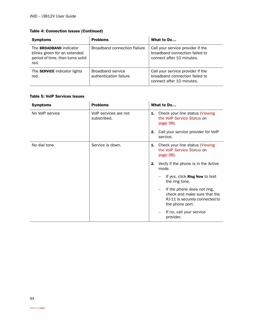
iNID -- i3812V User Guide
The BROADBAND indicator blinks green for an extended period of time, then turns solid red.
Broadband connection Failure Call your service provider if the broadband connection failed to connect after 10 minutes.
The SERVICE indicator lights red.
Broadband service authentication failure
Call your service provider if the broadband connection failed to connect after 10 minutes.
Table 5: VoIP Services Issues
Symptoms Problems What to Do…
No VoIP service VoIP services are not subscribed.
1. Check your line status (Viewing the VoIP Service Status on page 98).
2. Call your service provider for VoIP service.
No dial tone. Service is down. 1. Check your line status (Viewing the VoIP Service Status on page 98).
2. Verify if the phone is in the Active mode.
− If yes, click Ring Now to test the ring tone.
− If the phone does not ring, check and make sure that the RJ-11 is securely connected to the phone port.
− If no, call your service provider.
Table 4: Connection Issues (Continued)
Symptoms Problems What to Do…
94
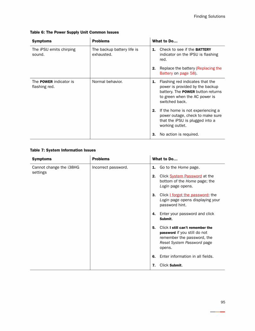
Finding Solutions
Table 6: The Power Supply Unit Common Issues
Symptoms Problems What to Do…
The iPSU emits chirping sound.
The backup battery life is exhausted.
1. Check to see if the BATTERY indicator on the IPSU is flashing red.
2. Replace the battery (Replacing the Battery on page 58).
The POWER indicator is flashing red.
Normal behavior. 1. Flashing red indicates that the power is provided by the backup battery. The POWER button returns to green when the AC power is switched back.
2. If the home is not experiencing a power outage, check to make sure that the iPSU is plugged into a working outlet.
3. No action is required.
Table 7: System Information Issues
Symptoms Problems What to Do…
Cannot change the i38HG settings
Incorrect password. 1. Go to the Home page.
2. Click System Password at the bottom of the Home page; the Login page opens.
3. Click I forgot the password; the Login page opens displaying your password hint.
4. Enter your password and click Submit.
5. Click I still can’t remember the password if you still do not remember the password, the Reset System Password page opens.
6. Enter information in all fields.
7. Click Submit.
95
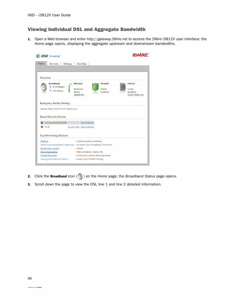
iNID -- i3812V User Guide
Viewing Individual DSL and Aggregate Bandwidth
1. Open a Web browser and enter http://gateway.2Wire.net to access the 2Wire i3812V user interface; the Home page opens, displaying the aggregate upstream and downstream bandwidths.
2. Click the Broadband icon ( ) on the Home page; the Broadband Status page opens.
3. Scroll down the page to view the DSL line 1 and line 2 detailed information.
96
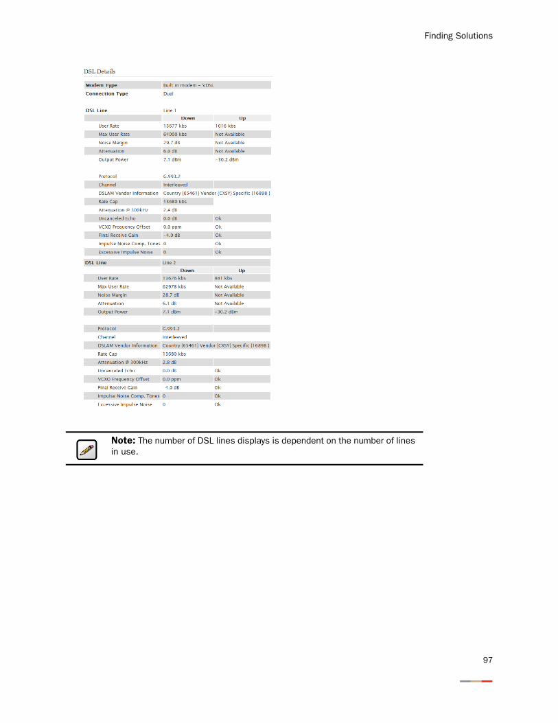
Finding Solutions
Note: The number of DSL lines displays is dependent on the number of lines in use.
97
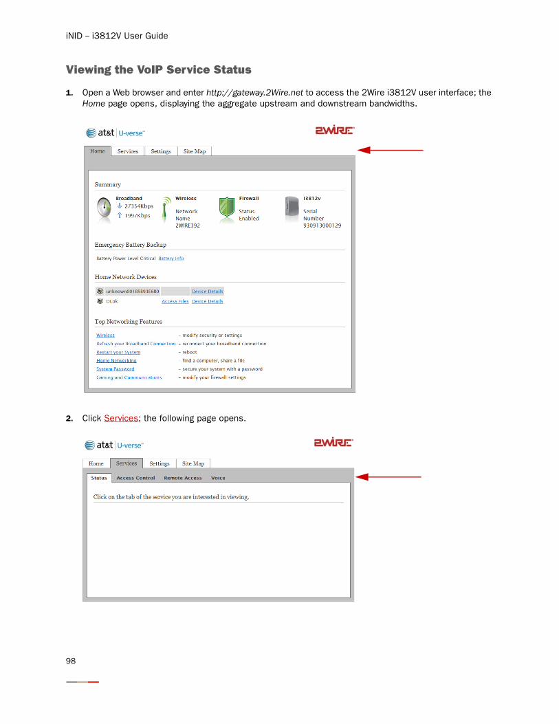
iNID -- i3812V User Guide
Viewing the VoIP Service Status
1. Open a Web browser and enter http://gateway.2Wire.net to access the 2Wire i3812V user interface; the Home page opens, displaying the aggregate upstream and downstream bandwidths.
2. Click Services; the following page opens.
98
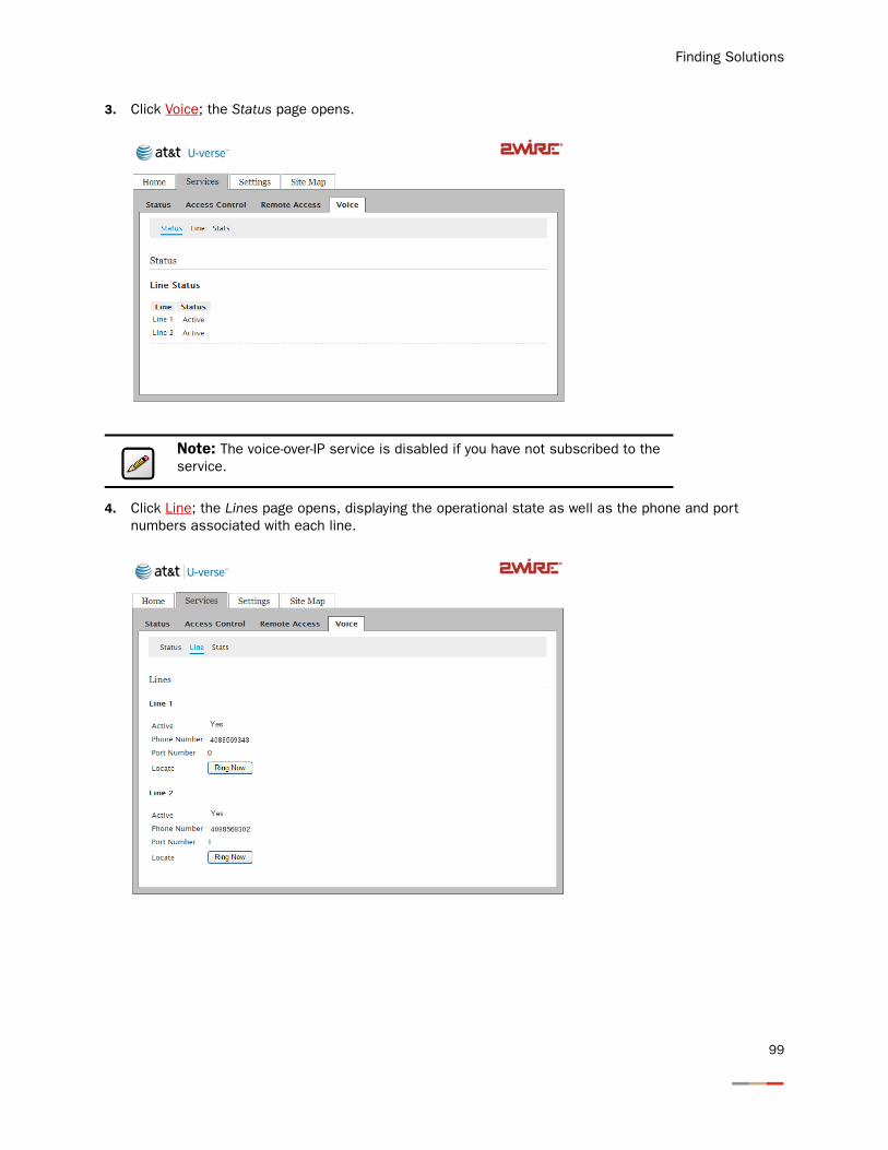
Finding Solutions
3. Click Voice; the Status page opens.
4. Click Line; the Lines page opens, displaying the operational state as well as the phone and port numbers associated with each line.
Note: The voice-over-IP service is disabled if you have not subscribed to the service.
99
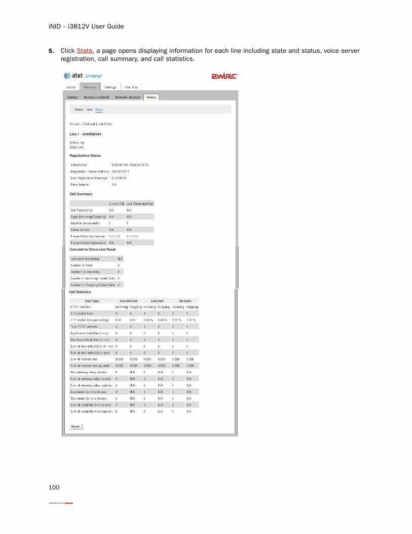
iNID -- i3812V User Guide
5. Click Stats, a page opens displaying information for each line including state and status, voice server registration, call summary, and call statistics.
100
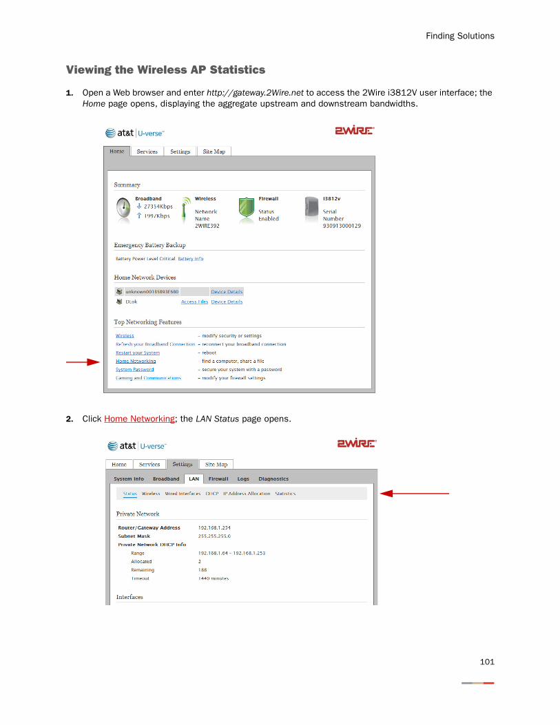
Finding Solutions
Viewing the Wireless AP Statistics
1. Open a Web browser and enter http://gateway.2Wire.net to access the 2Wire i3812V user interface; the Home page opens, displaying the aggregate upstream and downstream bandwidths.
2. Click Home Networking; the LAN Status page opens.
101
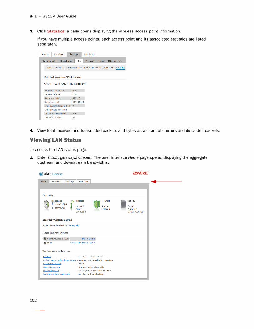
iNID -- i3812V User Guide
3. Click Statistics; a page opens displaying the wireless access point information.
If you have multiple access points, each access point and its associated statistics are listed separately.
4. View total received and transmitted packets and bytes as well as total errors and discarded packets.
Viewing LAN Status
To access the LAN status page:
1. Enter http://gateway.2wire.net. The user interface Home page opens, displaying the aggregate upstream and downstream bandwidths.
102
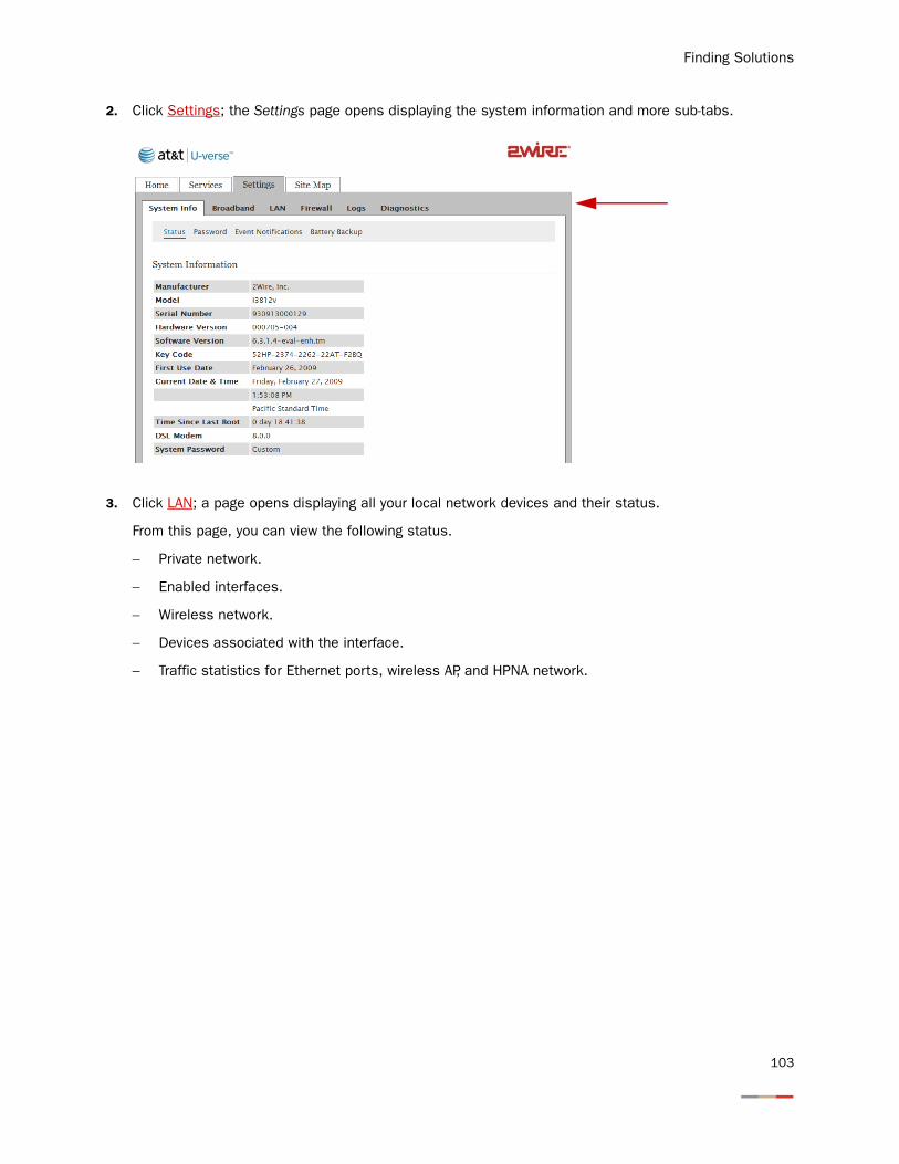
Finding Solutions
2. Click Settings; the Settings page opens displaying the system information and more sub-tabs.
3. Click LAN; a page opens displaying all your local network devices and their status.
From this page, you can view the following status.
− Private network.
− Enabled interfaces.
− Wireless network.
− Devices associated with the interface.
− Traffic statistics for Ethernet ports, wireless AP, and HPNA network.
103
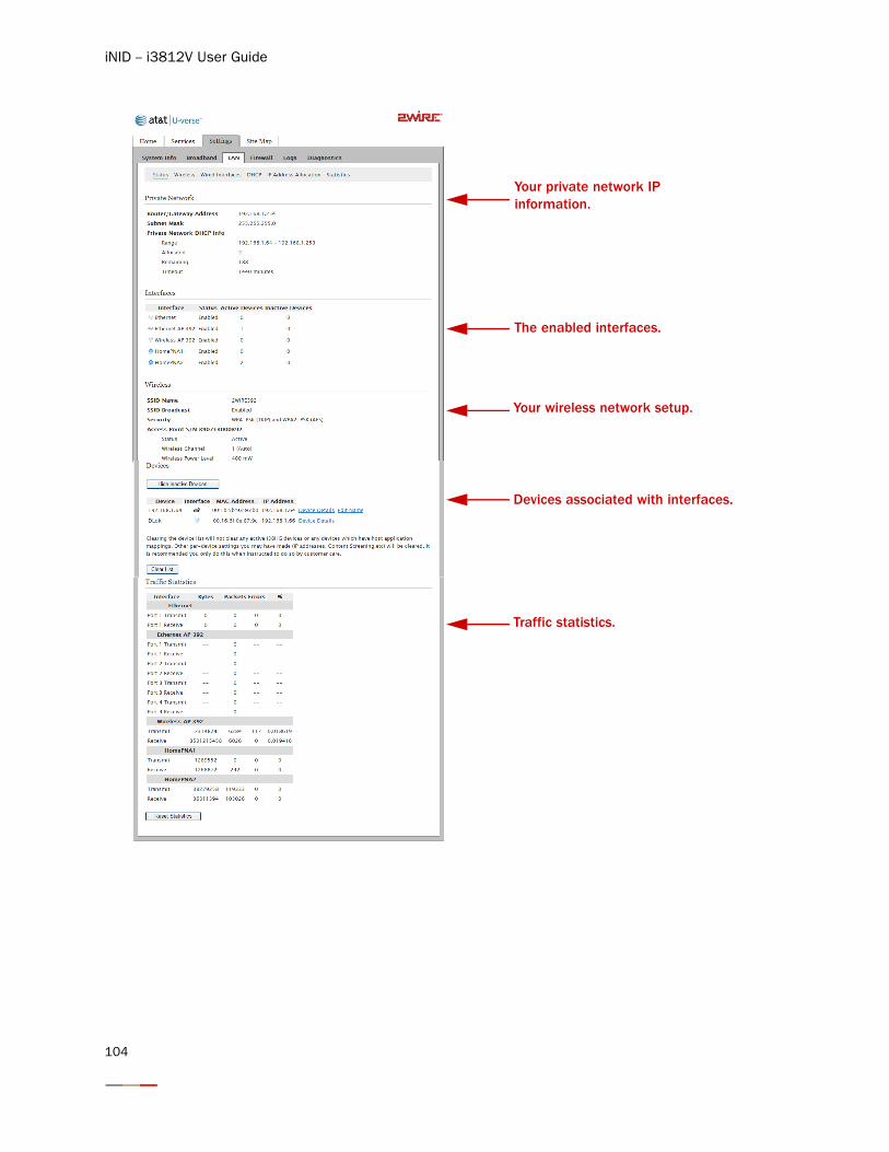
iNID -- i3812V User Guide
Your private network IP information.
The enabled interfaces.
Your wireless network setup.
Devices associated with interfaces.
Traffic statistics.
104
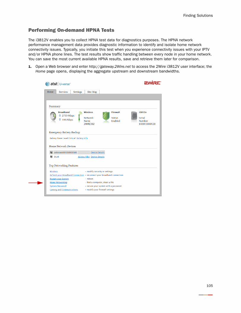
Finding Solutions
Performing On-demand HPNA Tests
The i3812V enables you to collect HPNA test data for diagnostics purposes. The HPNA network performance management data provides diagnostic information to identify and isolate home network connectivity issues. Typically, you initiate this test when you experience connectivity issues with your IPTV and/or HPNA phone lines. The test results show traffic handling between every node in your home network. You can save the most current available HPNA results, save and retrieve them later for comparison.
1. Open a Web browser and enter http://gateway.2Wire.net to access the 2Wire i3812V user interface; the Home page opens, displaying the aggregate upstream and downstream bandwidths.
105
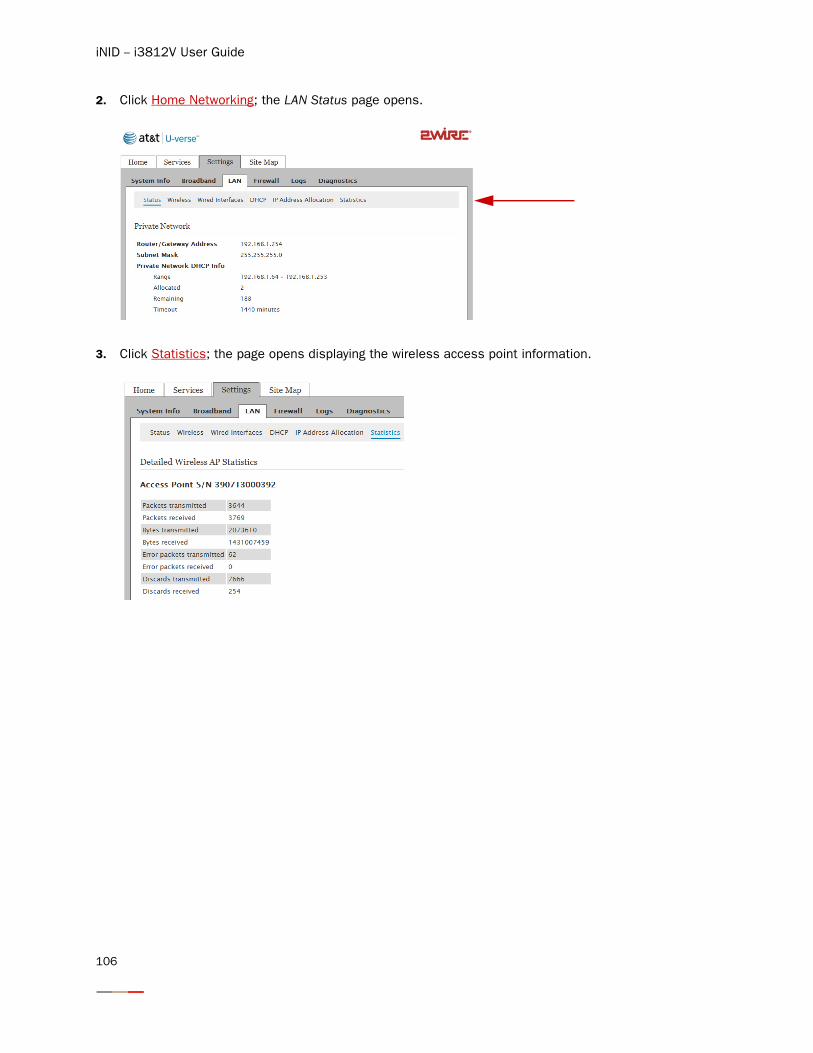
iNID -- i3812V User Guide
2. Click Home Networking; the LAN Status page opens.
3. Click Statistics; the page opens displaying the wireless access point information.
106
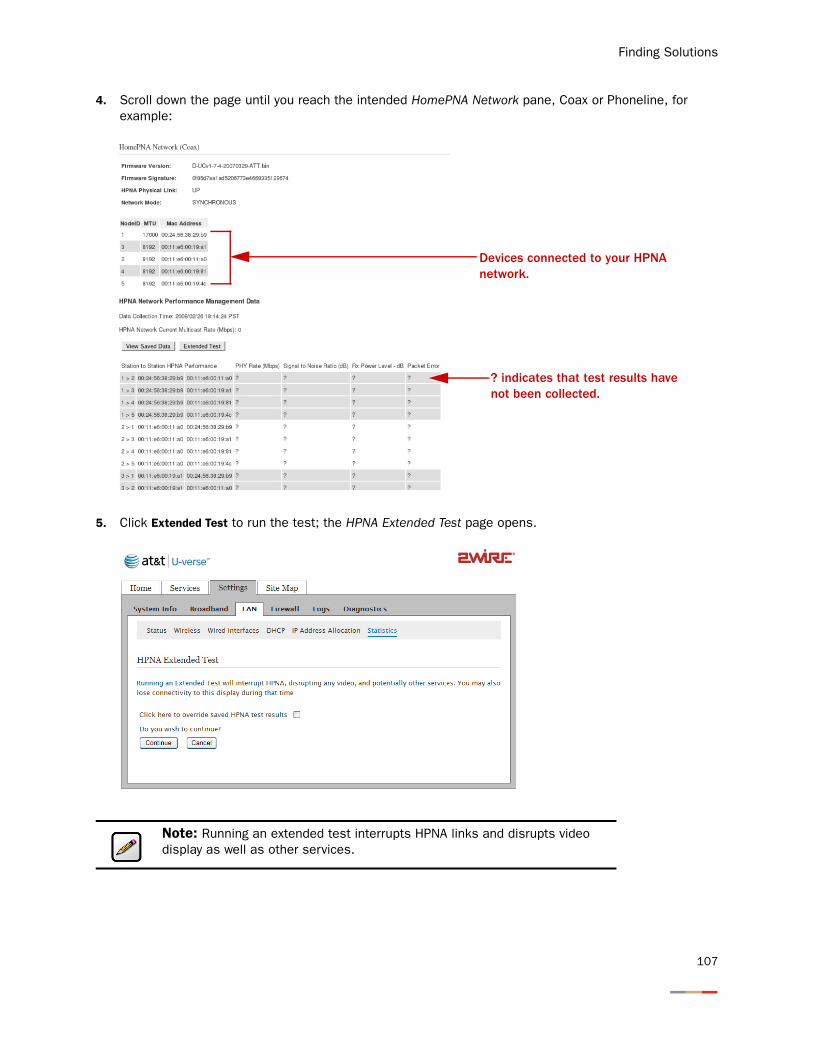
Finding Solutions
4. Scroll down the page until you reach the intended HomePNA Network pane, Coax or Phoneline, for example:
5. Click Extended Test to run the test; the HPNA Extended Test page opens.
Note: Running an extended test interrupts HPNA links and disrupts video display as well as other services.
Devices connected to your HPNA network.
? indicates that test results have not been collected.
107
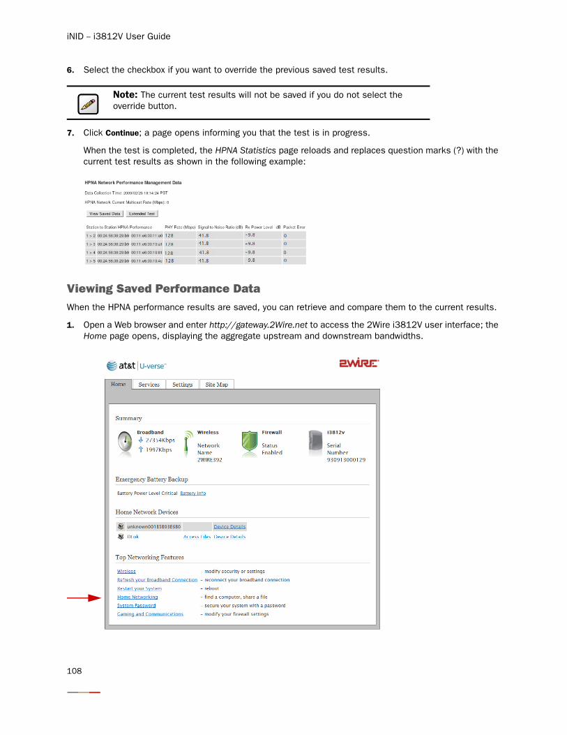
iNID -- i3812V User Guide
6. Select the checkbox if you want to override the previous saved test results.
7. Click Continue; a page opens informing you that the test is in progress.
When the test is completed, the HPNA Statistics page reloads and replaces question marks (?) with the current test results as shown in the following example:
Viewing Saved Performance Data When the HPNA performance results are saved, you can retrieve and compare them to the current results.
1. Open a Web browser and enter http://gateway.2Wire.net to access the 2Wire i3812V user interface; the Home page opens, displaying the aggregate upstream and downstream bandwidths.
Note: The current test results will not be saved if you do not select the override button.
108
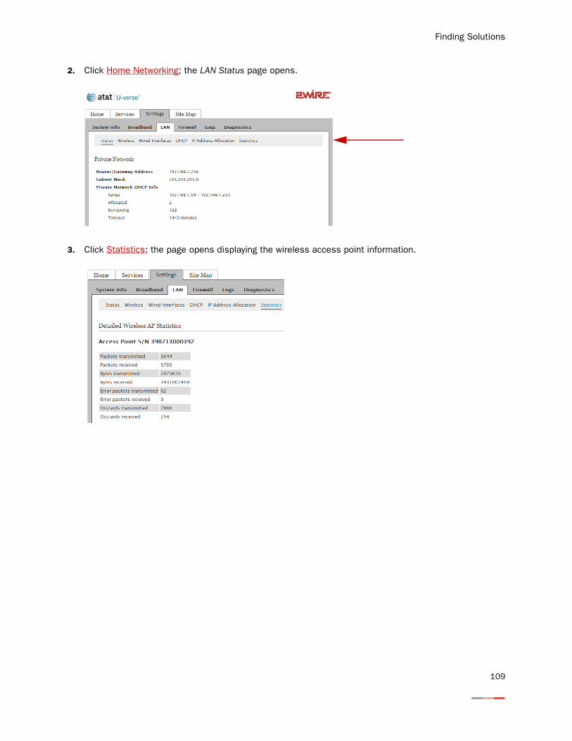
Finding Solutions
2. Click Home Networking; the LAN Status page opens.
3. Click Statistics; the page opens displaying the wireless access point information.
109
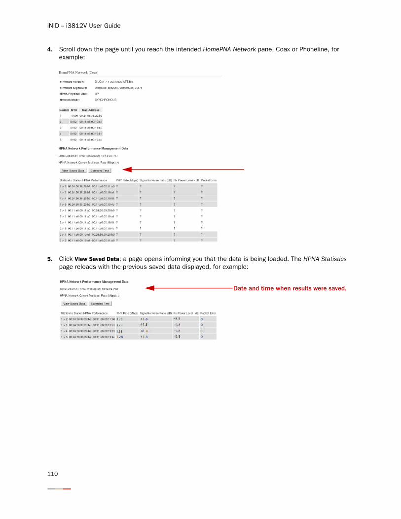
iNID -- i3812V User Guide
4. Scroll down the page until you reach the intended HomePNA Network pane, Coax or Phoneline, for example:
5. Click View Saved Data; a page opens informing you that the data is being loaded. The HPNA Statistics page reloads with the previous saved data displayed, for example:
Date and time when results were saved.
110
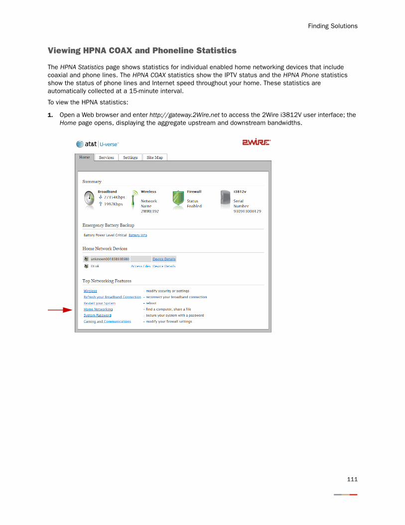
Finding Solutions
Viewing HPNA COAX and Phoneline Statistics
The HPNA Statistics page shows statistics for individual enabled home networking devices that include coaxial and phone lines. The HPNA COAX statistics show the IPTV status and the HPNA Phone statistics show the status of phone lines and Internet speed throughout your home. These statistics are automatically collected at a 15-minute interval.
To view the HPNA statistics:
1. Open a Web browser and enter http://gateway.2Wire.net to access the 2Wire i3812V user interface; the Home page opens, displaying the aggregate upstream and downstream bandwidths.
111
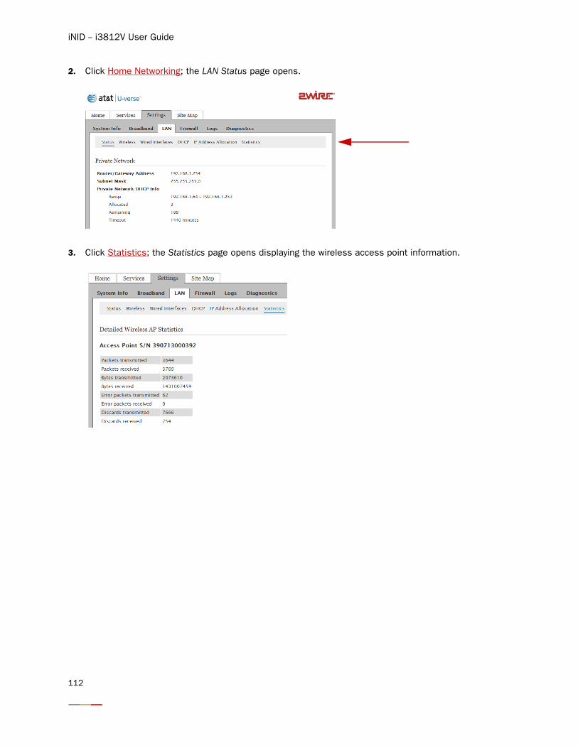
iNID -- i3812V User Guide
2. Click Home Networking; the LAN Status page opens.
3. Click Statistics; the Statistics page opens displaying the wireless access point information.
112
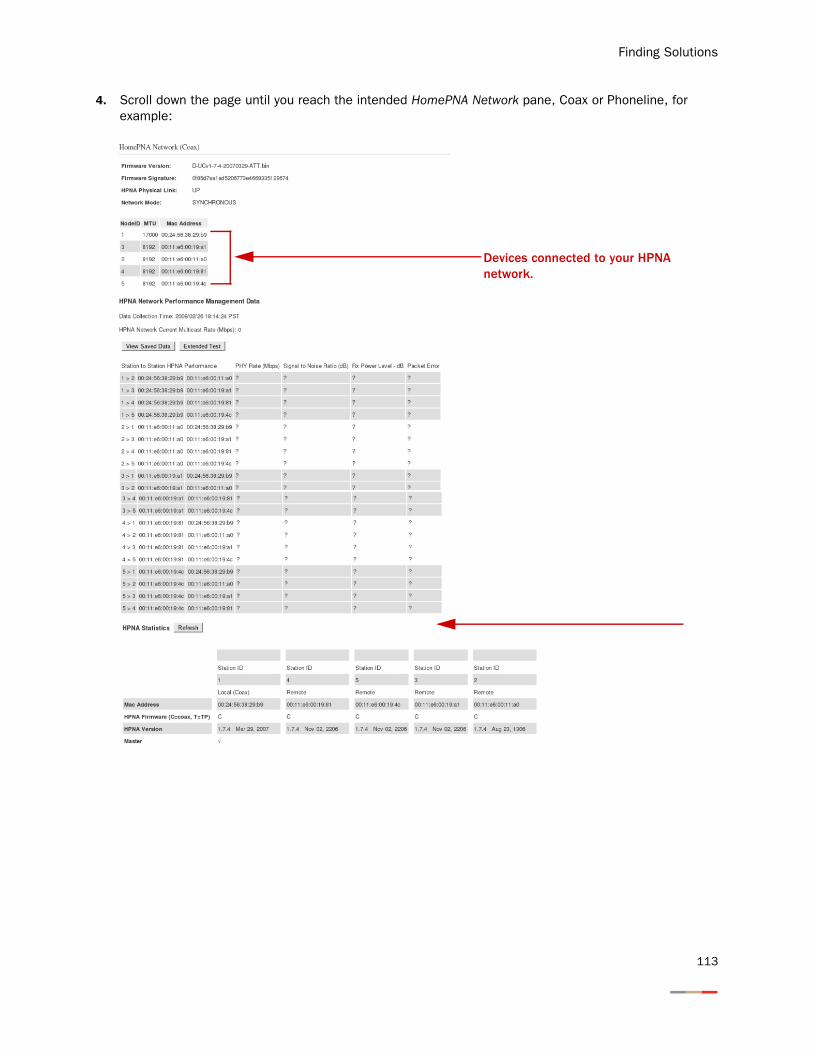
Finding Solutions
4. Scroll down the page until you reach the intended HomePNA Network pane, Coax or Phoneline, for example:
Devices connected to your HPNA network.
113
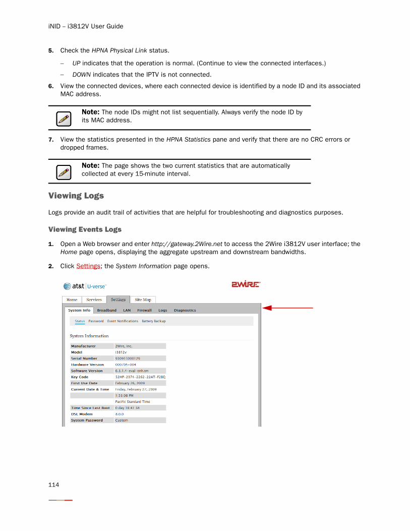
iNID -- i3812V User Guide
5. Check the HPNA Physical Link status.
− UP indicates that the operation is normal. (Continue to view the connected interfaces.)
− DOWN indicates that the IPTV is not connected.
6. View the connected devices, where each connected device is identified by a node ID and its associated MAC address.
7. View the statistics presented in the HPNA Statistics pane and verify that there are no CRC errors or dropped frames.
Viewing Logs
Logs provide an audit trail of activities that are helpful for troubleshooting and diagnostics purposes.
Viewing Events Logs
1. Open a Web browser and enter http://gateway.2Wire.net to access the 2Wire i3812V user interface; the Home page opens, displaying the aggregate upstream and downstream bandwidths.
2. Click Settings; the System Information page opens.
Note: The node IDs might not list sequentially. Always verify the node ID by its MAC address.
Note: The page shows the two current statistics that are automatically collected at every 15-minute interval.
114
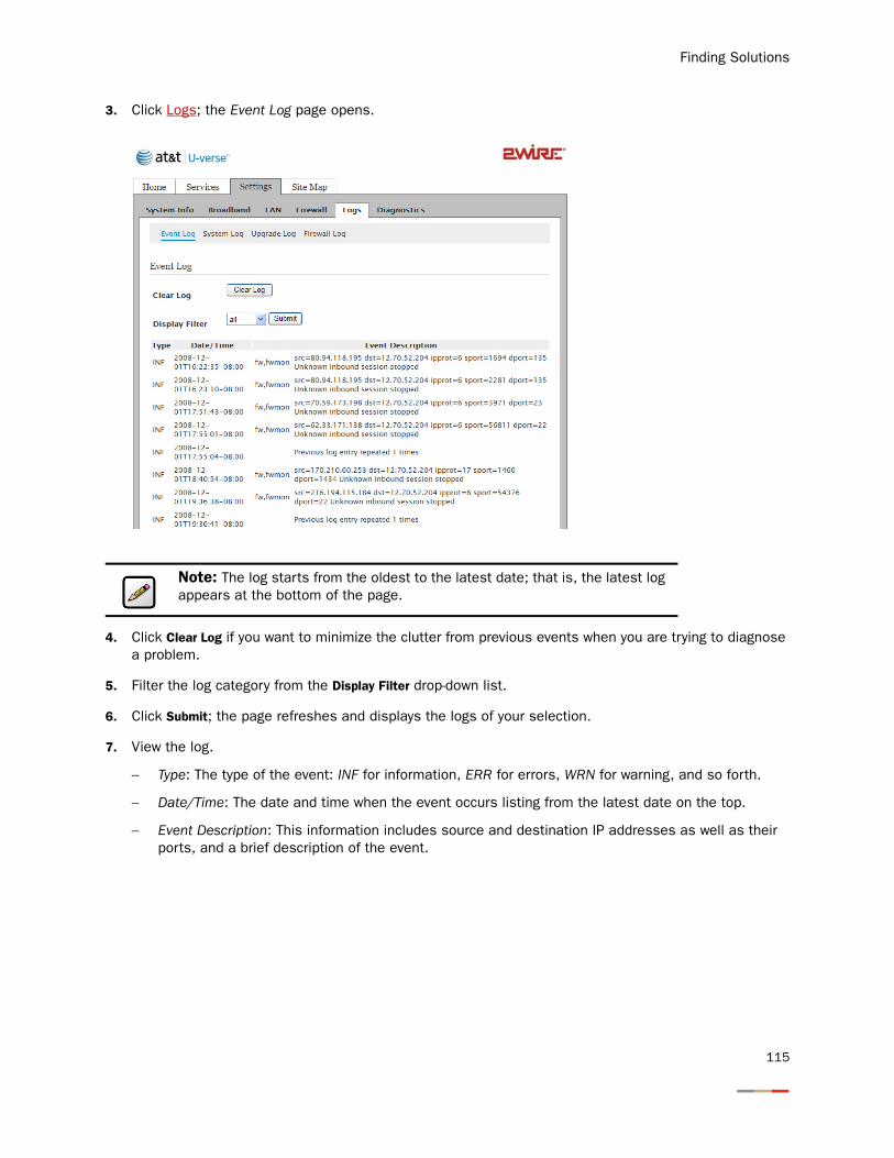
Finding Solutions
3. Click Logs; the Event Log page opens.
4. Click Clear Log if you want to minimize the clutter from previous events when you are trying to diagnose a problem.
5. Filter the log category from the Display Filter drop-down list.
6. Click Submit; the page refreshes and displays the logs of your selection.
7. View the log.
− Type: The type of the event: INF for information, ERR for errors, WRN for warning, and so forth.
− Date/Time: The date and time when the event occurs listing from the latest date on the top.
− Event Description: This information includes source and destination IP addresses as well as their ports, and a brief description of the event.
Note: The log starts from the oldest to the latest date; that is, the latest log appears at the bottom of the page.
115
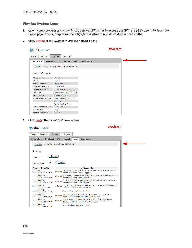
iNID -- i3812V User Guide
Viewing System Logs
1. Open a Web browser and enter http://gateway.2Wire.net to access the 2Wire i3812V user interface; the Home page opens, displaying the aggregate upstream and downstream bandwidths.
2. Click Settings; the System Information page opens.
3. Click Logs; the Event Log page opens.
116
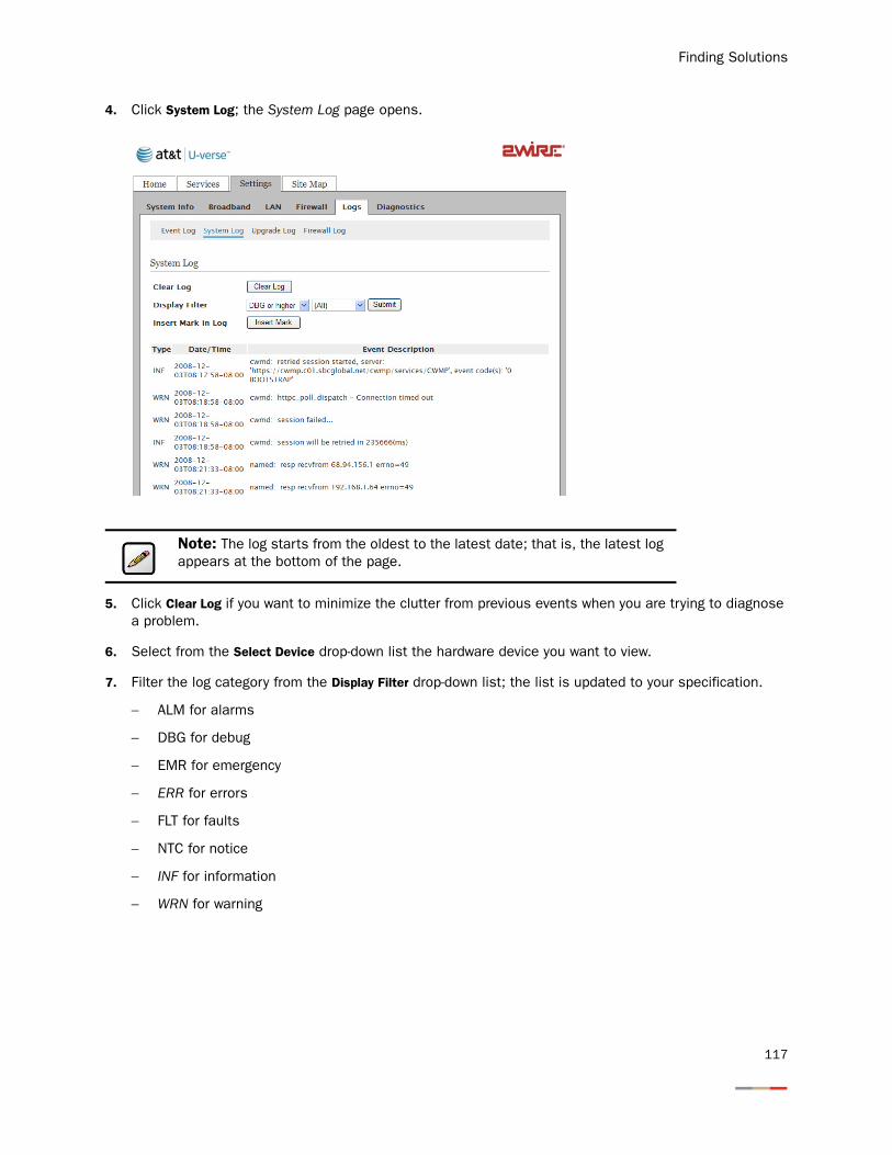
Finding Solutions
4. Click System Log; the System Log page opens.
5. Click Clear Log if you want to minimize the clutter from previous events when you are trying to diagnose a problem.
6. Select from the Select Device drop-down list the hardware device you want to view.
7. Filter the log category from the Display Filter drop-down list; the list is updated to your specification.
− ALM for alarms
− DBG for debug
− EMR for emergency
− ERR for errors
− FLT for faults
− NTC for notice
− INF for information
− WRN for warning
Note: The log starts from the oldest to the latest date; that is, the latest log appears at the bottom of the page.
117
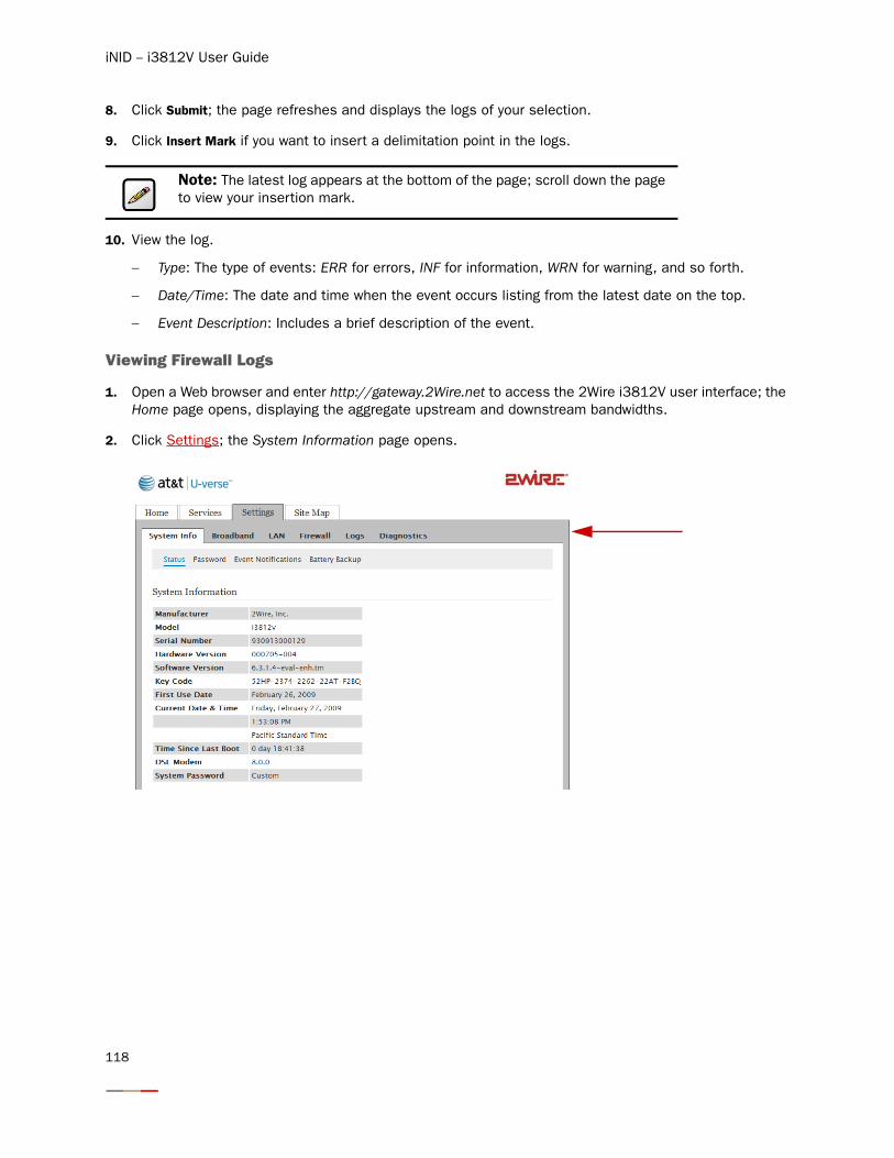
iNID -- i3812V User Guide
8. Click Submit; the page refreshes and displays the logs of your selection.
9. Click Insert Mark if you want to insert a delimitation point in the logs.
10. View the log.
− Type: The type of events: ERR for errors, INF for information, WRN for warning, and so forth.
− Date/Time: The date and time when the event occurs listing from the latest date on the top.
− Event Description: Includes a brief description of the event.
Viewing Firewall Logs
1. Open a Web browser and enter http://gateway.2Wire.net to access the 2Wire i3812V user interface; the Home page opens, displaying the aggregate upstream and downstream bandwidths.
2. Click Settings; the System Information page opens.
Note: The latest log appears at the bottom of the page; scroll down the page to view your insertion mark.
118
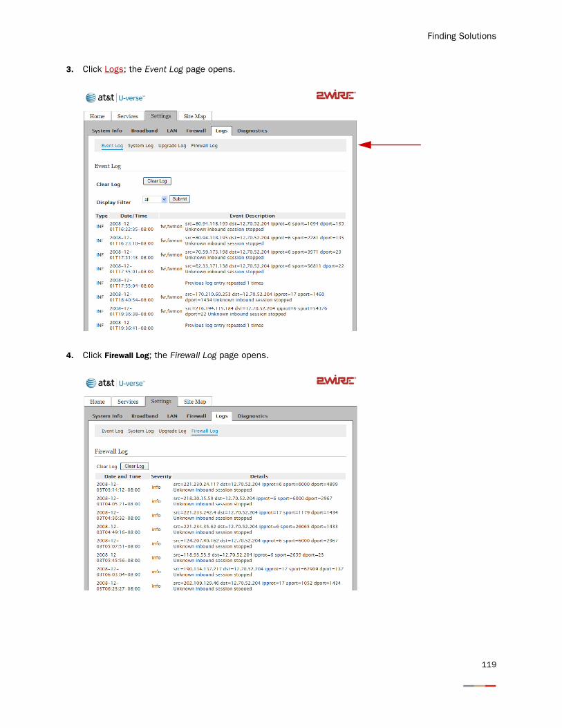
Finding Solutions
3. Click Logs; the Event Log page opens.
4. Click Firewall Log; the Firewall Log page opens.
119
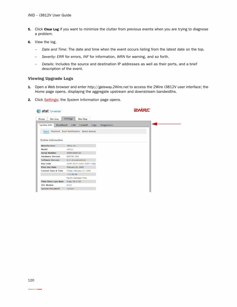
iNID -- i3812V User Guide
5. Click Clear Log if you want to minimize the clutter from previous events when you are trying to diagnose a problem.
6. View the log.
− Date and Time: The date and time when the event occurs listing from the latest date on the top.
− Severity: ERR for errors, INF for information, WRN for warning, and so forth.
− Details: Includes the source and destination IP addresses as well as their ports, and a brief description of the event.
Viewing Upgrade Logs
1. Open a Web browser and enter http://gateway.2Wire.net to access the 2Wire i3812V user interface; the Home page opens, displaying the aggregate upstream and downstream bandwidths.
2. Click Settings; the System Information page opens.
120
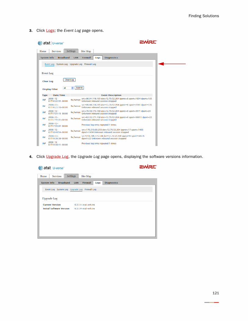
Finding Solutions
3. Click Logs; the Event Log page opens.
4. Click Upgrade Log, the Upgrade Log page opens, displaying the software versions information.
121

iNID -- i3812V User Guide
122
Replacing and Removing the i38HG
The i38HG (inside unit) is a home networking hub that provides an 802.11b/g Wi-Fi access point and Ethernet switch functions for connecting personal computers and other in-home networked devices to the service provider’s network. The i3812V (outside unit) is the gateway that acts as the network interface device. All wireless configuration data is stored on the outside unit. When your newly installed i38HG first talks to the iNID system, it is immediately configured with the iNID's current wireless configuration, including your Wireless Network Name and Wireless Key.
When you replace your i38HG, you do not need to reconfigure any setting on the new device. All your configuration information is automatically configured to the new device, including the network name and wireless key. This means that you do not need to reconfigure your devices connecting via wireless during a i38HG replacement.
Note: After replacing the i38HG, the information on the label of the i38HG will not be valid. You can change your network name and wireless key by going to the User Interface. Refer to the Setting up the Wireless Network Name section on page 25.
123

iNID -- i3812V User Guide
124
Regulatory Information
Electrical
AC Adapter
The AC adapter is designed to ensure your personal safety and to be compatible with this equipment. Please follow these guidelines:
• Do not use the adapter in a high moisture environment. Never touch the adapter when your hands or feet are wet.
• Allow adequate ventilation around the adapter. Avoid locations with restricted airflow.
• Connect the adapter to a proper power source. The voltage and grounding requirements are found on the product case and/or packaging.
• Do not use the adapter if the cord becomes damaged.
• Do not attempt to service the adapter. There are no serviceable parts inside. Replace the unit if it is damaged or exposed to excess moisture.
Telecommunication Cord
Location - Electrical Considerations
Caution: To reduce the risk of fire, use only No. 26 AWG or larger UL Listed or CSA Certified Telecommunication Line Cord.
Warning: The electrical cord of this product must be plugged into a properly grounded outlet or adapter. Failure to comply could result in an electric shock hazard. If you do not know whether your outlet or adapter is properly grounded, you should consult a licensed electrician.
Caution: Due to the risk of electrical shock or terminal damage, do not use the terminal near water, including a bathtub, wash bowl, kitchen sink or laundry tub, in a wet basement, or near a swimming pool. Also, avoid using this product during electrical storms. Avoid locations near electrical appliances or other devices that cause excessive voltage fluctuations or emit electrical noise (for example, air conditioners, neon signs, high-frequency or magnetic security devices, or electric motors).
125
iNID -- i3812V User Guide
Equipment
Repairs
Do not, under any circumstances, attempt any service, adjustments, or repairs on this equipment. Instead, contact your local 2Wire distributor or service provider for assistance. Failure to comply may void the product warranty.
Location – Environmental Considerations
Do not plug the power pack into an outdoor outlet or operate the terminal outdoors. It is not waterproof or dust proof, and is for indoor use only. Any damage to the unit from exposure to rain or dust may void your warranty.
Do not use the terminal where there is high heat, dust, humidity, moisture, or caustic chemicals or oils. Keep the gateway away from direct sunlight and anything that radiates heat, such as a stove or a motor.
Declaration of Conformity
FCC Compliance
This device has been tested and certified as compliant with the regulations and guidelines set forth in the Federal Communication commission - FCC part 15 and FCC part 68
Manufacturer: 2Wire, Inc.
Model: i38HG
Part 15 of FCC Rules
This device complies with Part 15 of the FCC Rules. Operation is subject to the following two conditions:
1. This device may not cause harmful interference, and
2. This device must accept any interference received, including interference that may cause undesired operation.
This equipment has been tested and found to comply with the limits for a Class B digital device, pursuant to part 15 of the FCC Rules. These limits are designed to provide reasonable protection against harmful interference in a residential installation. This equipment generates, uses and can radiate radio frequency energy and, if not installed and used in accordance with the instructions, may cause harmful interference to radio communications. However, there is no guarantee that interference will not occur in a particular installation. If this equipment does cause harmful interference to radio or television reception, which can be determined by turning the equipment off and on, the user is encouraged to try to correct the interference by one or more of the following measures:
• Reorient or relocate the receiving antenna.
• Increase the separation between the equipment and receiver.
• Connect the equipment into an outlet on a circuit different from that to which the receiver is connected.
• Consult the dealer or an experienced radio/TV technician for help.
Caution: Changes or modifications not expressly approved by the party responsible for compliance could void your authority to operate this equipment.
126
Regulatory Information
TIA 968 (Part 68 of FCC Rules)
This equipment complies with the Telecommunication Industry Association TIA-968 (FCC part 68) Telecommunication requirements. On the product is a label that contains, among other information, the FCC registration number and ringer equivalence number (REN) for this equipment. If requested, this information may be provided to the telephone company.
The REN is used to determine the quantity of devices that may be connected to the telephone line. Excessive RENs on the telephone line may result in the device not ringing in response to an incoming call. In most, but not all areas, the sum of the RENs should not exceed five (5.0)
To be certain of the number of devices that may be connected to the line, as determined by the total RENs, contact the telephone company to determine the maximum RENs for the calling area.
This terminal cannot be used on telephone-company-provided coin service. Connection to Party Line Service is subject to state tariffs.
This equipment uses the following TIA1096 compliance jacks: RJ11C.
An FCC-compliant telephone cord and modular plug is provided with this equipment. This equipment is designed to be connected to the telephone network or premises wiring using a compatible modular jack that is Part 68 compliant. If this equipment causes harm to the telephone network, the telephone company will notify you in advance that temporary discontinuance of service may be required. If advance notice is not practical, the telephone company will notify the customer as soon as possible. Also, you will be advised of your right to file a complaint with the FCC if you believe it is necessary. The telephone company may make changes in its facilities, equipment, operations, or procedures that could affect the operation of this equipment. If this happens, the telephone company will provide advance notice in order for you to make the necessary modifications to maintain uninterrupted service. If trouble is experienced with this equipment, please contact 2Wire, or your local 2Wire distributor or service center in the U.S.A. for repair and/or warrant information. If the trouble is causing harm to the telephone network, the telephone company may request you to remove this equipment from the network until the problem is resolved. No repairs can be done by a customer on this equipment. It is recommended that the customer install an AC surge arrestor in the AC outlet to which this device is connected. This is to avoid damage to the equipment caused by local lightning strikes and other electrical surges.
RF Exposure Information
This device was verified for RF exposure and found to comply with Council Recommendation 1999/519/EC and FCC OET-65 RF exposure requirements.
Wi-Fi Only
This equipment complies with FCC radiation exposure limits set forth for an uncontrolled environment. For additional compliance information, please reference FCC ID: PGR2Wi38HG.
MPE/SAR Labeling
Warning: While this device is in operation, a separation distance of at least 20 cm (8 inches) must be maintained between the radiating antenna inside the Equipment Under Test (EUT) and the bodies of all persons exposed to the transmitter in order to meet the FCC RF exposure guidelines. Making changes to the antenna or the device is not permitted. Doing so may result in the installed system exceeding RF exposure requirements. This device must not be co-located or operated in conjunction with any other antenna or radio transmitter. Installers and end users must follow the installation instructions provided in this guide.
127

iNID -- i3812V User Guide
128