Embed Size (px)
Citation preview

____________________________________________________________________________________________________________
V7 AC500 System Technology Couplers 1 PROFIBUS DP AC500 / Issued: 10.2006
Contents "The PROFIBUS DP Coupler"
1 The PROFIBUS DP Coupler ................................................................................................. 2
1.1 Brief overview ...................................................................................................................................... 2
1.1.1 Fundamental properties and fields of application............................................................................... 2
1.1.2 Features.............................................................................................................................................. 3
1.2 Technical data...................................................................................................................................... 4
1.2.1 Technical data of the coupler.............................................................................................................. 4
1.2.2 Technical data of the interface ........................................................................................................... 4
1.3 Connection and data transfer media ............................................................................................. 4
1.3.1 Attachment plug for the bus cable ...................................................................................................... 4
1.3.2 Bus terminating resistors .................................................................................................................... 5
1.3.3 Bus cable ............................................................................................................................................ 5
1.3.4 Maximum line lengths (bus segment)................................................................................................. 5
1.3.5 Repeaters ........................................................................................................................................... 6
1.4 Possibilities for networking ............................................................................................................. 7
1.4.1 Single master system ......................................................................................................................... 7
1.4.2 Multi master system............................................................................................................................ 8
1.5 PROFIBUS DP configuration example ........................................................................................ 10
1.5.1 Configuration .................................................................................................................................... 10
1.5.2 Running operation ............................................................................................................................ 25
1.5.3 Error diagnosis.................................................................................................................................. 26
1.5.4 Function blocks................................................................................................................................. 26
1.6 PROFIBUS DP diagnosis ................................................................................................................ 27
1.6.1 Status-LEDs...................................................................................................................................... 27
1.6.2 PROFIBUS DP error messages ....................................................................................................... 27
1.6.3 Function blocks................................................................................................................................. 27
1.7 Further information .......................................................................................................................... 28
1.7.1 Standardization................................................................................................................................. 28
1.7.2 Important addresses ......................................................................................................................... 28
1.7.3 Terms, definitions and abbreviations................................................................................................ 28
2 Index ................................................................................................................................................... 29

____________________________________________________________________________________________________________
V7 AC500 System Technology Couplers 2 PROFIBUS DP AC500 / Issued: 10.2006
1 The PROFIBUS DP Coupler
1.1 Brief overview
1.1.1 Fundamental properties and fields of application
PROFIBUS-DP is designed for the rapid transfer of process data between central controller modules (such as PLC or PC) and decentralized field modules (such as I/O modules, drives and valves) in the field level. The communication occurs mainly cyclic. For intelligent field modules, additionally acyclic communication functions are required for parameter assignment, diagnosis and alarm handling during the running cyclic data transfer.
During normal operation, a central controller (DP master of class 1) cyclically reads the input data of the connected decentralized I/O modules (DP slaves) and sends output data to them. Per slave a maximum of 244 bytes of input and output data can be transferred in one cycle.
Apart from the user data traffic, PROFIBUS-DP provides extensive commissioning and diagnosis functions. The present diagnosis messages of all slave modules are summarized in the master. This enables a quick localization of errors.
Using PROFIBUS-DP, mono-master systems and multi-master systems can be realized. Multi-master systems are built of functionally independent subsystems which each consist of one master and a portion of the slaves which are integrated in the entire system. Normal bus masters cannot exchange information with each other.
PROFIBUS-DP distinguishes two types of masters. The class 1 master carries out the cyclic transfer of user data with the slaves and supplies the user data. The class 1 master can be called by a class 2 master using specific functions. These functions are restricted services, for example the interrogation of diagnosis information of the slaves or the master itself. Thus, a class 2 master is also considered as a programming and diagnosis device.
PROFIBUS-DP uses the hybrid bus access method. This guarantees on the one hand that complex automation devices used as DP masters obtain the opportunity to handle their communication tasks in defined time intervals. On the other hand, it enables the cyclic and real-time related data exchange between the master and peripheral devices (DP slaves). The assigned slave modules on the bus are handled by the master one after the other using the polling operation mode. So, each slave becomes active only after it was requested by the master. This avoids simultaneous access to the bus.
The hybrid access method used with PROFIBUS allows a combined operation of multiple bus masters and even a mixed operation of PROFIBUS-DP and PROFIBUS-FMS in one bus section. This, however, assumes the correct configuration of the bus system and the unique assignment of the slave modules to the masters.
The characteristic properties of a PROFIBUS-DP module are documented in form of an electronic data sheet (modules master data file, GSD file). The modules master data describe the characteristics of a module type completely and clearly in a manufacturer independent format. Using this defined file format strongly simplifies the planning of a PROFIBUS-DP system. Usually the GSD files are provided by the module's manufacturer. In addition, the PROFIBUS user organization (PNO) makes the GSD files of numerous PROFIBUS-DP modules available for a free of charge download via internet in their GSD library. The address of the PROFIBUS user organization (PNO) is: http://www.profibus.com.

____________________________________________________________________________________________________________
V7 AC500 System Technology Couplers 3 PROFIBUS DP AC500 / Issued: 10.2006
1.1.2 Features
Transmission technique:
• RS485, potential separated, insulation voltage up to 850 V.
• Twisted pair cable or optical fibre as a medium for the bus.
• Transfer rate from 9.6 kbit/s up to 12 Mbit/s.
• Bus length up to 1200 m at 9.6 kbit/s and up to 100 m at 12 Mbit/s.
• Up to 32 subscribers (master and slave modules) without repeaters and up to 126 subscribers on one bus with repeaters.
• 9-pole SUB-D socket for bus connection; assignment according to standard.
• Integrated repeater controller.
Communication:
• Up to 244 bytes of input data and 244 bytes of output data per slave, 2944 I/O points max.
• Cyclic user data transfer between DP master and DP slave.
• Acyclic data transfer from master to master.
• Slave configuration check.
• Efficient diagnosis functions, 3 graduated diagnosis messaging levels.
• Synchronization of inputs and/or outputs via control commands.
Protection functions:
• Message transfer with Hamming distance HD = 4.
• Errors during data transfer are detected by the CRC check and cause a repetition of the telegram.
• Access protection for inputs and outputs of the slaves.
• Incorrect parameter settings are avoided since bus subscribers with faulty parameters are not included in the user data operation.
• A failure of a bus subscriber is registered in the master and indicated via a common diagnosis.
Status indication via 4 LEDs
• PWR (green): Supply voltage
• RDY (yellow): Coupler is ready for operation.
• RUN (green): Configuration and communication status.
• STA (yellow): Data exchange.
• ERR (red): PROFIBUS error.

____________________________________________________________________________________________________________
V7 AC500 System Technology Couplers 4 PROFIBUS DP AC500 / Issued: 10.2006
1.2 Technical data
1.2.1 Technical data of the coupler
Coupler type PROFIBUS coupler
Processor EC1-160, 48 MHz
Internal power supply with +5 V, 330 mA typ.
Internal RAM memory (EC1) 256 kbytes
External Flash memory 512 kbytes (firmware)
CE sign yes
1.2.2 Technical data of the interface
Interface socket 9-pole, SUB-D socket
Transmission standard EIA RS-485 acc. to EN 50170, potential-free
Transmission protocol PROFIBUS-DP, 12 Mbaud max.
Transmission rate Baudrate 9.6 kbit/s up to 12000 kbit/s
Status indication by 5 LEDs
Number of subscribers (master/slave modules per bus segment)
32 max.
Number of subscribers via repeaters 126 max.
1.3 Connection and data transfer media
1.3.1 Attachment plug for the bus cable
9-pin SUB-D connector, male
Assignment:
Pin No. Signal Meaning
1 Shield Shielding, protective earth
2 not used
3 RxD/TxD-P Reception / transmission line, positive
4 CBTR-P Control signal for repeater (optional)
5 DGND Reference potential for data lines and +5V
6 VP +5 V, supply voltage for bus terminating resistors
7 not used
8 RxD/TxD-N Reception / transmission line, negative
9 CNTR-N Control signal for repeater, negative (optional)
Table 1-1: Pin assignment of the attachment plug for the bus cable
Supplier:
e.g. Erbic® BUS Interface Connector
ERNI Elektroapparate GmbH Seestraße 9 D-72099 Adelberg, Germany Phone: +49 7166 50 176 Telefax: +49 7166 50 103 Internet: http://www.erni.com

____________________________________________________________________________________________________________
V7 AC500 System Technology Couplers 5 PROFIBUS DP AC500 / Issued: 10.2006
1.3.2 Bus terminating resistors
The line ends (of the bus segments) have to be terminated using bus terminating resistors according to the drawing below. The bus terminating resistors are usually placed inside the bus connector.
390 Ohms
220 Ohms
390 Ohms
VP (+5 V)
Data line B(RxD/TxD-P)
Data line A(RxD/TxD-N)
GND (0 V)
Configuration of the resistors Symbol
R
Figure: Bus terminating resistors connected to the line ends
1.3.3 Bus cable
Type Twisted pair cable (shielded)
Wave impedance (cable impedance) 135...165 Ω
Cable capacity (distributed capacitance) < 30 pF/m
Diameter of line cores (copper) ≥ 0.64 mm
Cross section of line cores ≥ 0.34 mm²
Line resistance per core ≤ 55 Ω/km
Loop resistance (serial resistance of 2 cores) ≤ 110 Ω/km
Supplier:
e.g. UNITRONIC® BUS U.I. LAPP GmbH Schulze-Delitzsch-Straße 25 D-70565 Stuttgart, Germany Phone: (+49) 711 7838 01 Telefax: (+49) 711 7838 264 Internet: http://www.lappkabel.de
1.3.4 Maximum line lengths (bus segment)
1200 m at a transfer rate of 9.6 / 19.2 / 93.75 kbit/s
1000 m at a transfer rate of 187.5 kbit/s
400 m at a transfer rate of 500 kbit/s
200 m at a transfer rate of 1500 kbit/s
100 m at a transfer rate of 3000 / 6000 / 12000 kbit/s
Branch lines are generally permissible for baud rates of up to 1500 kbit/s. But in fact they should be avoided for transmission rates higher than 500 kbit/s.

____________________________________________________________________________________________________________
V7 AC500 System Technology Couplers 6 PROFIBUS DP AC500 / Issued: 10.2006
1.3.5 Repeaters
One bus segment can have up to 32 subscribers. Using repeaters a system can be expanded to up to 126 subscribers. Repeaters are also required for longer transfer lines. Please note that a repeater's load to the bus segment is the same as the load of a normal bus subscriber. The sum of normal bus subscribers and repeaters in one bus segment must not exceed 32.
Station 32 Station 61
Bus segment 2:max. 30 stations+ 2 repeaters
R Repeater RR Repeater R
Station 1 Station 31
Bus segment 1:max. 31 stations+ 1 repeater
Rmax. 200 m max. 200 m
Figure: Principle example for a PROFIBUS-DP system with repeaters (1500 kbit/s baud rate)

____________________________________________________________________________________________________________
V7 AC500 System Technology Couplers 7 PROFIBUS DP AC500 / Issued: 10.2006
1.4 Possibilities for networking
The PROFIBUS coupler is connected to the bus via the 9-pole SUB-D socket. For EMC suppression and protection against dangerous contact voltages, the shield of the bus line has to be connected to protective earth outside the housing.
1.4.1 Single master system
The single master system is the simplest version of a PROFIBUS network. It consists of a class 1 DP master and one or more DP slaves. Up to 31 DP slaves can be connected to the bus without using a repeater. If the number of bus segments is increased by means of repeaters, up to 126 DP slaves can be handled. The line ends of the bus segments have to be terminated using bus terminating resistors.
The DP master of class 1 is able to:
1. Parameterize DP slaves (e.g. timing supervision, bus interchange).
2. Configure DP slaves (e.g. type / number of channels).
3. Read input and output data of the DP slaves.
4. Write output data of the DP slaves.
5. Read diagnosis data of the DP slaves.
6. Send control commands to the DP slaves (e.g. freezing input signals).

____________________________________________________________________________________________________________
V7 AC500 System Technology Couplers 8 PROFIBUS DP AC500 / Issued: 10.2006
07 DC 92
R
R
PROFIBUS DP
07 KT 9x
DP Slave 2e.g. valve island
DP Slave 31e.g. power
CS
31 s
yste
m b
us
I/O modules
PM581 asDP MasterClass 1
PM581 asDP Slave 1
inverter
Figure: Single master system example
1.4.2 Multi master system
A PROFIBUS network containing several DP masters is called a multi-master system. Up to 32 subscribers (DP masters and DP slaves) can be operated on one bus segment. Using repeaters the system can be expanded to up to 126 subscribers. In a multi-master system no data exchange between the DP masters is performed. The entire system is divided into logical subsystems inside of which one DP master communicates with the assigned DP slaves. Each DP slave can be assigned to only one DP master. The master has unlimited access to its assigned slaves while all other masters on the bus can only read the input and output data of these slaves.
All DP masters of class 1 (normal bus master, here: AC500) and class 2 (commissioning device, typically a PC) can read the input and output data of all slaves.
Additionally the DP masters of class 1 and class 2 have the following access possibilities to their assigned DP slaves. They are able to:
• Parameterize DP slaves (e.g. timing supervision, bus interchange). • Configure DP slaves (e.g. type / number of channels). • Write output data of the DP slaves. • Read diagnosis data of the DP slaves. • Send control commands to the DP slaves (e.g. freezing input signals).

____________________________________________________________________________________________________________
V7 AC500 System Technology Couplers 9 PROFIBUS DP AC500 / Issued: 10.2006
A DP master of class 2 is additionally able to:
• Read and write configuration data of the class 1 DP masters. • Read configuration data of the DP slaves. • Read diagnosis data of the class 1 DP masters. • Read out the diagnosis data of the DP slaves assigned to the respective DP master.
07 DC 92
R
R
PROFIBUS DP
07 KT 9x
DP Slave 28e.g. valve island
DP Slave 29e.g. power
CS
31 s
yste
m b
us I/O modules
PM581 asDP Slave 1
PM581 asDP Master Class 1
DP MasterClass 2 (PC)
PM581 asDP Master Class 1
inverter
Figure: Multi master system example

____________________________________________________________________________________________________________
V7 AC500 System Technology Couplers 10 PROFIBUS DP AC500 / Issued: 10.2006
1.5 PROFIBUS DP configuration example
1.5.1 Configuration
The integration of the coupler in the PLC configuration is an assumption for the correct function of the PROFIBUS coupler CM572. Configuration of the coupler and the connected PROFIBUS subscribers is done using the tool SYCON.net which is part of the CoDeSys programming software.
The PROFIBUS DP coupler CM572 has to be configured as the PROFIBUS master. The PROFIBUS slave functionality is made available via the FBP interface and an FBP PROFIBUS plug.
The following construction is used as an example of a PROFIBUS configuration:
DC532 AX522DC532DC505 AX522
PM581CM572
PM581 DC532CM572
DC532 DI524DC505-FBP DX522 AX522
PDP22-FBP
AC500 configuration: CPU (PM581) with an expansion DC532 at the I/O-Bus as well as one decentralized expansion over PROFIBUS (CM572) with the devices PDP22-FBP, DC505-FBP as well as the S500 modules DC532, DI524, DX522 and AX522.
____________________________________________________________________________________________________________
V7 AC500 System Technology Couplers 11 PROFIBUS DP AC500 / Issued: 10.2006
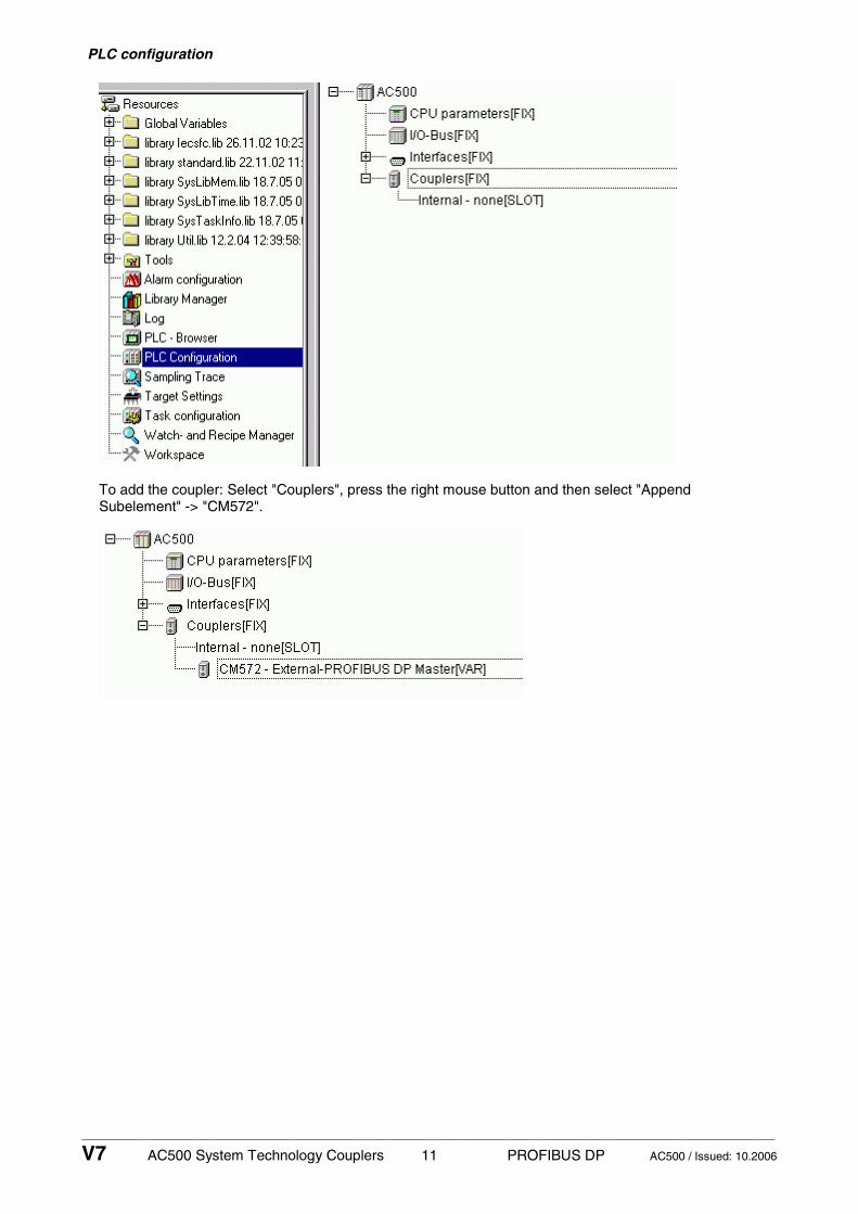
PLC configuration
To add the coupler: Select "Couplers", press the right mouse button and then select "Append Subelement" -> "CM572".

____________________________________________________________________________________________________________
V7 AC500 System Technology Couplers 12 PROFIBUS DP AC500 / Issued: 10.2006
Do not change the default values for the coupler parameters.
The coupler is now integrated in the PLC configuration.
For the following example, an I/O module (DC532) is then inserted into this configuration at the I/O-Bus.
For the module settings of the DC532, the default values are left as is.

____________________________________________________________________________________________________________
V7 AC500 System Technology Couplers 13 PROFIBUS DP AC500 / Issued: 10.2006
Declaration of the I/Os of the devices is done byte-by-byte.
Inputs: By_LE_DC532_I_0 By_LE_DC532_I_1 By_LE_DC532_I_2 By_LE_DC532_I_3
Outputs: By_LE_DC532_O_0 By_LE_DC532_O_1
Configuration using SYCON.net
When configuring the PROFIBUS coupler, the configuration data are a definite element of a project. They are created in CoDeSys using the tool SYCON.net (Resources tab -> Tools / SYCON.net). The transfer of the configuration data to the coupler is done within the SYCON.netTool.

____________________________________________________________________________________________________________
V7 AC500 System Technology Couplers 14 PROFIBUS DP AC500 / Issued: 10.2006
The following overview is loaded after starting the configuration tool SYCON.net.
In the top right window, click on the entry "CM572-DPM" and drag it onto the green line displayed in the middle window. Correct insertion positions are displayed by a "+".
A dialog appears where you have to select the card number according to the coupler slot. The first slot left of the CPU is slot 1 (or card number 1).
In order to configure the coupler, place the cursor on the "CM572" icon and then press the right mouse button and select "Configuration".

____________________________________________________________________________________________________________
V7 AC500 System Technology Couplers 15 PROFIBUS DP AC500 / Issued: 10.2006
In the folder "Bus parameters", choose the baud rate for the PROFIBUS and then confirm the remaining parameters with "OK".
Next the PROFIBUS slaves are configured. In the top right window, click on the entry "PDP22-FBP (DPV1 modular)" in the folder "PROFIBUS DPV 0/Slave" and drag it onto the purple line (PROFIBUS line) displayed in the middle window. Correct insertion positions are displayed by a "+".
In order to configure the PROFIBUS slave, select the slave, then press the right mouse button and choose "Configuration".

____________________________________________________________________________________________________________
V7 AC500 System Technology Couplers 16 PROFIBUS DP AC500 / Issued: 10.2006
In this example, the folder "General" remains unchanged. If the station address should not equal the HW address, this can be adapted correspondingly after the configuration of the slaves in the configuration window of the master in the folder "station address".
In the next step, all the modules are configured, which are connected to the PDP22-FBP DPV1. For this, change into the folder "Configuration/Modules".

____________________________________________________________________________________________________________
V7 AC500 System Technology Couplers 17 PROFIBUS DP AC500 / Issued: 10.2006
Select the individual modules in the window "Available Modules" beginning with the S500 head station "DC505-FBP" and append them to the "configured modules" by using "Append". The order of the "configured modules" should represent the existing hardware.

____________________________________________________________________________________________________________
V7 AC500 System Technology Couplers 18 PROFIBUS DP AC500 / Issued: 10.2006
Now the modules are configured.
Next the parameters of the individual modules are defined. Change to the folder "Configuration/Parameters" and select the first device "DC505-FBP" using "Module".

____________________________________________________________________________________________________________
V7 AC500 System Technology Couplers 19 PROFIBUS DP AC500 / Issued: 10.2006
In this tab, you can set the device parameters of the individual I/O modules.
A selection of possible parameters can be displayed by double clicking on the settings in the "Value" column.
For the digital devices the settings always apply to the entire module. For the analog devices the settings additionally have to be performed for each channel.

____________________________________________________________________________________________________________
V7 AC500 System Technology Couplers 20 PROFIBUS DP AC500 / Issued: 10.2006
The setting of the parameters is completed now. All other settings can be left as is. Exit the configuration of the "PDP22-FBP (DPV1 modular)" and the modules by clicking on "OK".
After the configuration of the PROFIBUS slaves has been finished, the PROFIBUS station addresses can be set. This is carried out using the configuration window of the PROFIBUS master. Call the master configuration once more and change to the folder "Configuration/Station table".

____________________________________________________________________________________________________________
V7 AC500 System Technology Couplers 21 PROFIBUS DP AC500 / Issued: 10.2006
The station address of the slave can be set now. All other settings can be taken on.
The configuration can be loaded down into the PROFIBUS master now. To do this, the interface must be defined first, via which the data are loaded into the coupler. The corresponding interface can be configured over the configuration window of the PROFIBUS master in the register "Settings/Drivers/3S Gateway Driver".

____________________________________________________________________________________________________________
V7 AC500 System Technology Couplers 22 PROFIBUS DP AC500 / Issued: 10.2006
Select "Configure Gateway".
The configuration tool SYCON.net is looking now for PROFIBUS couplers which are connected to the indicated interface. A list of the detected PROFIBUS couplers can be looked through over the configuration window of the PROFIBUS master register "Equipment Allocation".

____________________________________________________________________________________________________________
V7 AC500 System Technology Couplers 23 PROFIBUS DP AC500 / Issued: 10.2006
Select the representing coupler and confirm with "OK" then.
Move cursor on "CM572", click the right mouse button and "Connect".
CM572 is shaded green.
Put the control system to Stop.
Move cursor on "CM572", click the right mouse button and "Download".
Confirm query with "Yes".

____________________________________________________________________________________________________________
V7 AC500 System Technology Couplers 24 PROFIBUS DP AC500 / Issued: 10.2006
After the successful download the "PWR LED" is on and the "RUN LED" flashes at the CM572.
Move cursor on "CM572", click right mouse button and "Disconnect".
The configuration of the coupler is now completed.
The variable names can be listed in the field "Variable Name". A double-click leads into the corresponding entry field.
In order to use the PROFIBUS data in the PLC program, the physical addresses should be assigned corresponding variable names with SYCON.net. These variables are available in the Control Builder then and can be used directly.
The netConnect window of the SYCON.net is used here.
You can enter the variable names in the field "Variable Name". Double click to open the corresponding input field.
All variables which were declared here are written down on the directory of the "Global Variables" automatically at the focus change from SYCON.net to Control Builder.

____________________________________________________________________________________________________________
V7 AC500 System Technology Couplers 25 PROFIBUS DP AC500 / Issued: 10.2006
The declaration of the variables is completed now. The coupler variables can be used now in the user program.
For the test of the PROFIBUS configuration, the inputs "In 0...7" of the module DC532 are copied to the outputs "Out 8...15" of the module DC505 in the user program.
The user program can now be transmitted and started in the control system.
The exchange of the PROFIBUS data is indicated by a permanent "ON" of the "RUN LED", shown at the CM572.
1.5.2 Running operation
The PROFIBUS-DP protocol is automatically handled by the coupler and the operating system of the controller. The coupler is only active on the bus if it was correctly initialized before and if the user program is running. No connection elements are required for the cyclic exchange of process data via PROFIBUS-DP. Special PROFIBUS-DP functions can be realized using the function blocks of the corresponding PROFIBUS library.
Communication via PROFIBUS is established by the coupler when starting the user program and starts with the initialization of the configured slaves. After its successful initialization, the slave is added to the cyclic process data exchange. The "RDY" LED lights up steadily after at least one slave was successfully taken into operation. If the user program is stopped, the coupler shuts down the PROFIBUS system in a controlled manner.

____________________________________________________________________________________________________________
V7 AC500 System Technology Couplers 26 PROFIBUS DP AC500 / Issued: 10.2006
The DP master operation mode is completely integrated to the operating system of the controller. The transmit or receive data of the slaves can be directly accessed in the corresponding operand areas. Access can be performed either via operands or symbolically. No function blocks are required.
The function block library contains various blocks which can be used e.g. to poll status information of the coupler or to execute specific acyclic PROFIBUS-DP functions. If necessary, these blocks can be inserted additionally.
1.5.3 Error diagnosis
PROFIBUS-DP communication errors are generally indicated by the red "ERR" LED of the coupler. Malfunctions of the PROFIBUS driver or the coupler itself are additionally indicated via the E error flags and the corresponding LEDs of the CPU. Furthermore, the PROFIBUS library provides different function blocks that allow a detailed error diagnosis. Amongst other things, the following information can be polled:
o the condition of the coupler itself,
o a detailed PROFIBUS diagnosis of an individual slave or
o a system diagnosis overview.
1.5.4 Function blocks
Control Builder
Libraries Remark
V1.0 V1.0 or later PROFIBUS_Master_S90_V43.LIB Coupler_AC500_V10.LIB
Table 1-2: Overview of PROFIBUS libraries
Profibus_Master_AC500_V10.LIB
Group Function block Function
General
PROFI_INFO Reading of coupler information
Status / Diagnosis
DPM_STAT Reading the coupler status
DPM_SLVDIAG Reading the detailed PROFIBUS diagnosis of a slave
DPM_SYSDIAG Reading the system diagnosis
Controller
DPM_CTRL Sending control commands to slaves
Acyclic reading
DPM_READ_INPUT Reading input data of slaves which are not assigned to the master
DPM_READ_OUTPUT Reading output data of slaves which are not assigned to the master
Table 1-3: Function blocks contained in the library PROFIBUS_Master_AC500_V10.LIB
Coupler_AC500_V10.LIB
Contains various internal functions which are used by the corresponding field bus coupler libraries.

____________________________________________________________________________________________________________
V7 AC500 System Technology Couplers 27 PROFIBUS DP AC500 / Issued: 10.2006
1.6 PROFIBUS DP diagnosis
1.6.1 Status LEDs
The following figure shows the positions of the five status LEDs.
CM572
PWRRDYRUN
STAERR
POWERREADYRUN
STATUSERROR
Figure: Positions of the status LEDs
LED Color Status Meaning
on Supply voltage available PWR green
off Supply voltage not available
on Coupler ready
flashes cyclic Bootstrap loader active
flashes irregularly Hardware or system error
RDY yellow
off Defective hardware
on Communication is running
flashes cyclic Communication stopped
flashes irregularly Missing or faulty configuration
RUN green
off No communication
DP slave: data exchange with DP master on
DP master: sending data or token
DP slave: no data exchange
STA yellow
off
DP master: no token
on PROFIBUS error ERR red
off no error
Table: Meanings of the status LEDs
1.6.2 PROFIBUS-DP error messages
The PROFIBUS error messages are listed in section ‚Error messages of the couplers‘.
1.6.3 Function blocks
PROFIBUS-DP master
DPM_STAT Reading the coupler status
DPM_SLVDIAG Reading the detailed PROFIBUS diagnosis of a slave
DPM_SYSDIAG Reading the system diagnosis
PROFIBUS-DP slave
DPS_STAT Reading the coupler status

____________________________________________________________________________________________________________
V7 AC500 System Technology Couplers 28 PROFIBUS DP AC500 / Issued: 10.2006
Online diagnosis
The online diagnosis is described in the documentation for the field bus configuration tool SYCON.net .
1.7 Further information
1.7.1 Standardization
• EN 50170 • DIN 19245 part 1 • DIN 19245 part 3
1.7.2 Important addresses
PROFIBUS Nutzerorganisation e.V. (PNO) Haid-und-Neu-Straße 7 Germany, D-76131 Karlsruhe Phone: (+49) 721 9658 590 Telefax: (+49) 721 9658 589 Internet: http://www.profibus.com
1.7.3 Terms, definitions and abbreviations
PROFIBUS DP PROCESS FIELDBUS - DECENTRALIZED PERIPHERY
DPM1 DP master (class 1), normal bus master
DPM2 DP master (class 2), commissioning device
DPS DP slave
GSD Modules master data
DPV1 Guideline for functional expansions of PROFIBUS DP
PNO PROFIBUS Nutzer Organisation (PROFIBUS user organization)

____________________________________________________________________________________________________________
V7 AC500 System Technology Couplers 29 PROFIBUS DP AC500 / Issued: 10.2006
2 Index
A
attachment plug for the bus cable 4 (1.3.1)
B
brief overview 2 (1.1)
bus cable 5 (1.3.3)
bus terminating resistors 5 (1.3.2)
C
Configuration 10 (1.5.1)
connection and data transfer media 4 (1.3)
E
error diagnosis 26 (1.5.3)
F
Features 3 (1.1.2)
function blocks 26 (1.5.4)
function blocks 27 (1.6.3)
fundamental properties and fields of application 2 (1.1.1)
further information 28 (1.7)
I
important addresses 28 (1.7.2)
interface specification 4 (1.2.2)
M
maximum line lengths (bus segment) 5 (1.3.4)
multi master system 8 (1.4.2)
P
possibilities for networking 7 (1.4)
PROFIBUS-DP configuration example 10 (1.5)
PROFIBUS-DP coupler 2 (1.0)
PROFIBUS-DP diagnosis 27 (1.6)
PROFIBUS-DP error messages 27 (1.6.2)

____________________________________________________________________________________________________________
V7 AC500 System Technology Couplers 30 PROFIBUS DP AC500 / Issued: 10.2006
R
Repeaters 6 (1.3.5)
running operation 25 (1.5.2)
S
single master system 7 (1.4.1)
standardization 28 (1.7.1)
status LEDs 27 (1.6.1)
T
technical data 4 (1.2)
technical data of the coupler 4 (1.2.1)
terms, definitions and abbreviations 28 (1.7.3)


![BU 2700 PROFIBUS DP Busschnittstelle - NORD€¦ · Sicherheit/PROFIBUS DP [BU 2700]/Bestimmungsgemäße Ver wendung PROFIBUS DP @ 8\mod_1461835577600_6.docx @ 2249428 @ 2 @ 1 2.1](https://img.pdfslide.net/doc/110x75/5eab6d581394d0309b74d9e9/bu-2700-profibus-dp-busschnittstelle-nord-sicherheitprofibus-dp-bu-2700bestimmungsgeme.jpg)