Embed Size (px)
Citation preview

1
MDC2ARTEH DC SPINDLE UNIT
Maintenance Manual
CONTENTS
1. Main features 22. Composition 23. Operating conditions 24. Technical specifications 25. General structure and operation principles 26. Interface 5
6.1. Interface description 56.2. Connection diagram 7
7. Installation of DC spindle unit 87.1. Installation conditions 87.2. Outer dimensions 8
8. Electronic self-protections 89. Adjustment of DC spindle drive unit 9
9.1. Test equipment 109.2. Adjustment method 10
ARTEH Ltd. “MLADOST” 2 - 16 8800 SLIVEN BULGARIATEL/FAX (00359) 44 86238 TEL (00359) 44 35282 (00359) 44 74183 E-MAIL [email protected]
2
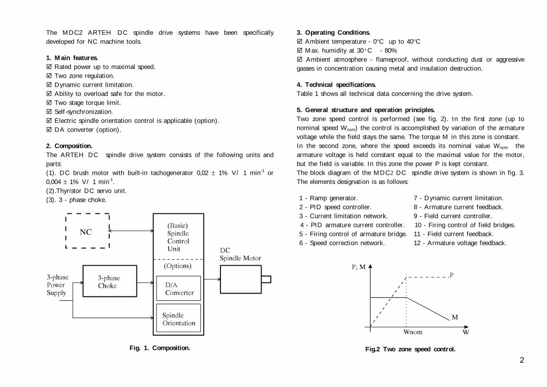
The MDC2 ARTEH DC spindle drive systems have been specificallydeveloped for NC machine tools.
1. Main features. Rated power up to maximal speed. Two zone regulation. Dynamic current limitation. Ability to overload safe for the motor. Two stage torque limit. Self-synchronization. Electric spindle orientation control is applicable (option). DA converter (option).
2. Composition.The ARTEH DC spindle drive system consists of the following units andparts:(1). DC brush motor with built-in tachogenerator 0,02 ± 1% V/ 1 min-1 or0,004 ± 1% V/ 1 min-1.(2).Thyristor DC servo unit.(3). 3 - phase choke.
Fig. 1. Composition.
3. Operating Conditions. Ambient temperature - 0°C up to 40°C Max. humidity at 30ºC - 80% Ambient atmosphere - flameproof, without conducting dust or aggressive
gasses in concentration causing metal and insulation destruction.
4. Technical specifications.Table 1 shows all technical data concerning the drive system.
5. General structure and operation principles.Two zone speed control is performed (see fig. 2). In the first zone (up tonominal speed Wnom) the control is accomplished by variation of the armaturevoltage while the field stays the same. The torque M in this zone is constant.In the second zone, where the speed exceeds its nominal value Wnom thearmature voltage is held constant equal to the maximal value for the motor,but the field is variable. In this zone the power P is kept constant.The block diagram of the MDC2 DC spindle drive system is shown in fig. 3.The elements designation is as follows:
1 - Ramp generator. 7 - Dynamic current limitation. 2 - PID speed controller. 8 - Armature current feedback. 3 - Current limitation network. 9 - Field current controller. 4 - PID armature current controller. 10 - Firing control of field bridges. 5 - Firing control of armature bridge. 11 - Field current feedback. 6 - Speed correction network. 12 - Armature voltage feedback.
Fig.2 Two zone speed control.

3
MP132MB MP160M MP160MA MP160L5 MDC1-18.5 MDC1-22 MDC1-22 MDC1-30
PK-02510 PK-02612 PK-02612 PK-02715
18.5 22 22 30
Hz 3x380, 50Hz 3x380, 50Hz 3x380, 50Hz 3x380, 50Hz
56 67 64 100
112 132 128 150
400 400 400 400
3.5 6.5 6.5 6
180 180 180 180
1000 1000 1000 1000
4500 4000 4500 4000
1:1000 1:1000 1:1000 1:1000
+/-10 +/-10 +/-10 +/-10
s continuous continuous continuous continuous
IP20 IP20 IP20 IP20
Table 1. Technical data.Motor type MP132SA MP132SB MP112M MP112L MP132M MP132MA ÌP132LASpindle unittype
MDC1-5.5 MDC1-5.5 MDC1-5.5 MDC1-7.5 MDC1-11 MDC1-11 MDC1-1
Choketype
PK- 0525 PK- 0525 PK-0525 PK-0548 PK-0548 PK-0548 PK-05410
Ratedpower, kW
5.5 5.5 5.5 7.5 11 11 15
Power supply,V
3x380, 50Hz 3x380, 50Hz 3x380, 50Hz 3x380, 50Hz 3x380, 50Hz 3x380, 50Hz 3x380, 50
Rated armaturecurrent, À
20 19 20 25 34 34 46
Maximalarmaturecurrent, A
40 38 40 50 68 68 92
Maximalarmaturevoltage, V
400 400 400 400 400 400 400
Rated fieldcurrent, À
2.5 2.5 4 4.5 5.8 3.5 5
Maximalfieldvoltage, V
180 180 180 180 110 180 180
Rated rotationspeed,n/min-1
1000 1000 1000 1000 1000 1000 1000
Maximalrotation speed,n/min-1
4500 5500 5500 5500 3500 4500 4500
Speed controlrange
1:1000 1:1000 1:1000 1:1000 1:1000 1:1000 1:1000
Speed referencesignal, V
+/-10 +/-10 +/-10 +/-10 +/-10 +/-10 +/-10
Mode ofoperation
continuous continuous continuous continuous continuous continuous continuou
Degree ofprotection
IP20 IP20 IP20 IP20 IP20 IP20 IP20

4
f armature bridge; 6- Speed correction network; 7- Dynamicd current feedback; 12- Armature voltage feedback;
Fig. 3. Block diagram.1- Ramp generator; 2- PID speed controler; 3- Current limitation network; 4- PID armature current controller; 5- Firing control o
current limitation; 8- Armature current feedback; 9- Field current controller; 10- Firing control of field bridges; 11- Fiel

5
6. Interface.6.1. Interface description.
Fig.4. Interface.
6
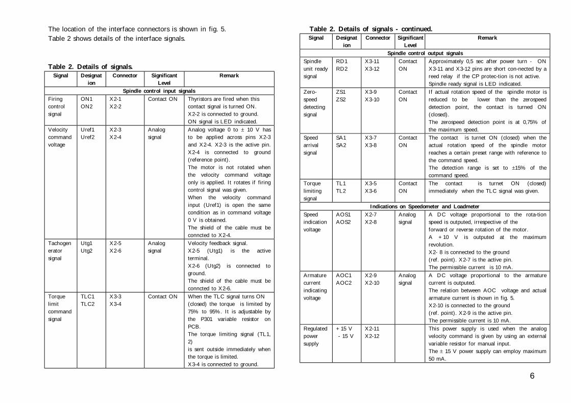
The location of the interface connectors is shown in fig. 5.Table 2 shows details of the interface signals.
Table 2. Details of signals.Signal Designat
ionConnector Significant
LevelRemark
Spindle control input signalsFiringcontrolsignal
ON1ON2
X2-1X2-2
Contact ON Thyristors are fired when thiscontact signal is turned ON.X2-2 is connected to ground.ON signal is LED indicated.
Velocitycommandvoltage
Uref1Uref2
X2-3X2-4
Analogsignal
Analog voltage 0 to ± 10 V hasto be applied across pins X2-3and X2-4. X2-3 is the active pin.X2-4 is connected to ground(reference point).The motor is not rotated whenthe velocity command voltageonly is applied. It rotates if firingcontrol signal was given.When the velocity commandinput (Uref1) is open the samecondition as in command voltage0 V is obtained.The shield of the cable must beconncted to X2-4.
Tachogeneratorsignal
Utg1Utg2
X2-5X2-6
Analogsignal
Velocity feedback signal.X2-5 (Utg1) is the activeterminal.X2-6 (Utg2) is connected toground.The shield of the cable must beconncted to X2-6.
Torquelimitcommandsignal
TLC1TLC2
X3-3X3-4
Contact ON When the TLC signal turns ON(closed) the torque is limited by75% to 95%. It is adjustable bythe P301 variable resistor onPCB.The torque limiting signal (TL1,2)is sent outside immediately whenthe torque is limited.X3-4 is connected to ground.
Table 2. Details of signals - continued.Signal Designat
ionConnector Significant
LevelRemark
Spindle control output signalsSpindleunit readysignal
RD1RD2
X3-11X3-12
ContactON
Approximately 0,5 sec after power turn - ONX3-11 and X3-12 pins are short con-nected by areed relay if the CP protec-tion is not active.Spindle ready signal is LED indicated.
Zero-speeddetectingsignal
ZS1ZS2
X3-9X3-10
ContactON
If actual rotation speed of the spindle motor isreduced to be lower than the zerospeeddetection point, the contact is turned ON(closed).The zerospeed detection point is at 0,75% ofthe maximum speed.
Speedarrivalsignal
SA1SA2
X3-7X3-8
ContactON
The contact is turnet ON (closed) when theactual rotation speed of the spindle motorreaches a certain preset range with reference tothe command speed.The detection range is set to ±15% of thecommand speed.
Torquelimitingsignal
TL1TL2
X3-5X3-6
ContactON
The contact is turnet ON (closed)immediately when the TLC signal was given.
Indications on Speedometer and LoadmeterSpeedindicationvoltage
AOS1AOS2
X2-7X2-8
Analogsignal
A DC voltage proportional to the rota-tionspeed is outputed, irrespective of theforward or reverse rotation of the motor.A +10 V is outputed at the maximumrevolution.X2- 8 is connected to the ground(ref. point). X2-7 is the active pin.The permissible current is 10 mA.
Armaturecurrentindicatingvoltage
AOC1AOC2
X2-9X2-10
Analogsignal
A DC voltage proportional to the armaturecurrent is outputed.The relation between AOC voltage and actualarmature current is shown in fig. 5.X2-10 is connected to the ground(ref. point). X2-9 is the active pin.The permissible current is 10 mA.
Regulatedpowersupply
+15 V - 15 V
X2-11X2-12
This power supply is used when the analogvelocity command is given by using an externalvariable resistor for manual input.The ± 15 V power supply can employ maximum50 mA.

7
Note:1. The permissible DC current through all reedrelay contacts is 50 mA.2. X3-1 and X3-2 connectors are reserved for future upgrade.
6.2. Connection diagram.Connections between DC spindle servo unit, DC spindle motor, CNC andmains supply are shown in fig. 6.
m2 S2, mm2 S3, mm2 S4, mm2 S5, mm2
1.5 4 0.35 41.5 4 0.35 41.5 6 0.35 61.5 6 0.35 62.5 10 0.35 102.5 10 0.35 10
Fig.6 Connection diagram.
Fig.5. The location of the interface connectors.S1, m5.5 kW 17.5 kW 111 kW 115 kW 1
18.5 kW 122 kW 1
8
Notes:1. Use wires as short as possible.2. The signal wires must be placed as far as possible from the power cables.3. Utilization of shielded wire is recommended for connection between NC system andreference inputs Uref1 and Uref2 of the drive unit. The shield has to be connected tothe X2-4 pin.4. Utilization of shielded wire is also recommended for connection between tacho-generator and speed feedback inputs Utg1 and Utg2 of the drive unit. The shield has tobe connected to the X2-6 pin.
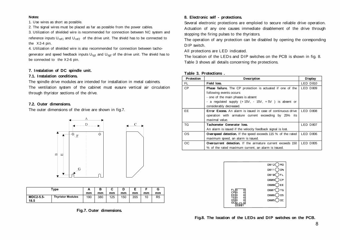
7. Instalation of DC spindle unit.7.1. Instalation conditions.The spindle drive modules are intended for installation in metal cabinets.The ventilation system of the cabinet must eusure vertical air circulationthrough thyristor sections of the drive.
7.2. Outer dimensions.The outer dimensions of the drive are shown in fig.7.
Type Amm
Bmm
Cmm
Dmm
Emm
Fmm
Gmm
MDC2-5.5-18.5
Thyristor Modules 190 380 125 150 355 10 R5
Fig.7. Outer dimensions.
8. Electronic self - protections.Several electronic protections are emploied to secure reliable drive operation.Actuation of any one causes immediate disablement of the drive throughstopping the firing pulses to the thyristors.The operation of any protection can be disabled by opening the corespondingDIP switch.All protections are LED indicated.The location of the LEDs and DIP switches on the PCB is shown in fig. 8.Table 3 shows all details concerning the protections.
Table 3. Protections .Protection Description Display
FL Field loss. LED D810CP Phase failure. The CP protection is actuated if one of the
following events occurs:- one of the main phases is absent- a regulated supply (+15V, - 15V, +5V ) is absent orconsiderably decreased.
LED D809
EE Error Excess. An alarm is issued in case of continuous driveoperation with armature current exceeding by 25% itsmaximal value.
LED D808
TG Tachometer Generator loss.An alarm is issued if the velocity feedback signal is lost.
LED D807
OS Overspeed detection. If the speed exceeds 115 % of the ratedmaximum speed, an alarm is issued.
LED D806
OC Overcurrent detection. If the armature current exceeds 150% of the rated maximum current, an alarm is issued.
LED D805
Fig.8. The location of the LEDs and DIP switches on the PCB.

9
9. Adjustment of the DC spindle drive unit.All necessary adjustments of the drive unit are implemented by themanufacturer. Readjustment may be done when it is needed. For this purposevariable resistors are employed and test points are implaned to facilitateobservation of the most important signals.Table 4 shows the designation of the variable resistors.Table 5 shows the designation of the test points.The location of the variable resistors and test points is shown in fig.9.
Table 4. Variable resistors.Item Designation Test pointP201 Speed feedback gain adjustment CP201P202 Acceleration and deceleration adjustment (ramp generator) CP204P203 Speed controller gain adjustment -P204 Offset of the ramp generator CP204P205 Offset of the speed controller -P301 Level of torque limit when TLC command was given -P401 Balancing of the armature voltage feedback defference amplifier CP401P402 Second zone adjustment CP402P403 Field current adjustment CP403P501 Armature current limitation -P502 Initial angle -
Table 5. Test points.Test point Signal RemarkCP101 Reference point (GROUND) 0VCP102CP103
+24V- 24V
CP104CP105CP106
+15V- 15V+5V
CP201 Tachogenerator voltage -10V to +10VCP202 Speed controller output -11V to +11VCP203 Armature current controller output -12V to +12VCP204 RAMP output -10V to+10VCP303 Armature currentCP301 Armature current feedback 2V/ maximal armature currentCP302 Armature current limitation 11V/ 0 rpm , 4V/ maximal speedCP401 Armature voltage feedbackCP402 Second zone of controlCP403 Field current feedback 6V/ nominal field currentCP404 Analog voltage proportional to the firing
angle of field thyristor bridge0V to +5V
CP501 Analog voltage proportional to the firingangle of armature thyristor bridge
0V to +5V Fig.9. Location of the variable resistors and test points.

10
9.1. Test equipment.Test equipment required for setting and adjustment of the DC spindle servounit is as follows:1. DC voltmeter.2. Variable DC voltage generator with range ±10V and output impedance upto 2 kΩ.
9.2. Adjusment method.When the DC spindle drive unit is installed and the power and interfacecables are connected the following steps have to be performed for it properadjustment:1. Short jumpers J202 and J203 .This makes the velocity and armature current regulators proportional.2. Disable the TG tacho loss protection turning OFF the coresponding switchlocated at the DS801 DIP switches.3. Disconnect the Utg1 signal. This disables the speed feedback.4. Turn ON the power.Check the rotation of the fan motor. If it is not correct, turn OFF the powerand exchange two of fan motor power supply phases.Then turn ON the power again.5. The RD (Ready) LED has to light.If it is not, there is some trouble or wrong connection.Turn OFF the power and check all connections again.6. After the RD (Ready) LED is lighted give the ON (firing control) signal.The ON LED is lighted and the thyristors are fired.7. Give Uref1 (velocity command) signal. The motor begins to rotate. Change the polarity of the Uref1 signal. The direction of the motor rotationhas to be changed.8. Check the polarities of the voltages at the CP204 test point and of theUtg1 signal. They has to be opposite. If they are not, exchange theconnections of the tachogenerator.9. Turn OFF the power supply.Connect the Utg1 signal to the X2-5 pin.Open the J202 and J203 jumpers.10. Turn ON the power supply.Use the P203 variable resistor to adjust the speed controler gain and the P202variable resistor to adjust the ramp generator according the mechanical load.

Sheet 1 of 12
MDC2 ArtTech
20 June 2000.
A
B
C
D
E
F
G
H
J
K
L
M
A
B
C
D
E
F
G
H
K
L
J
X1-2
X1-3
X1-1
18A
18B
0V
(2A4)
(2B2)
X2-1
X2-2
X2-3
X2-4
ON2
Uref1
Uref2
(9K3)
(3G0)
ON1
X2-6 Utg2
X2-8
X2-10
X2-5 Utg1 (3B1)
X2-7 AOS (3C3)(4G4)(9D3)(10C0)
X2-9 AOC (4B1)(6J3)(9B0)
+15
-15
X2-11
X2-12
X3-1 RESERVED
X3-3 (4L4)
X3-6 TL2
X3-8 SA2
X3-10 ZS2
X3-2
X3-4 TLC2
X3-5 TL1 (4K4)
X3-7 SA1 (10D4)
X3-9 ZS1 (10B1)
X3-11
X3-12
TLC1
(4L3)
(10E2)
(10B4)
RD1 (9C1)
RD2 (9C4)
X4-28GF2(11E0)
X4-5
X4-3
A2X4-1
X4-4
X4-2GA1
GA2
(7H1)
(7H2)
X4-6GA3(7H3)
(7K1)(5D0)
X4-34N R1(11H3)
(4B4)
(11H1)
(4C0)
(4C2)
X4-27
CT1 X4-30
CT2 X4-32
CT3 X4-33
X4-29 CTF1
X4-31 AGND
(5K2)
X1 X2 X3
1 3 1 12 1 12
X4
1
X4-7
X4-9
R (7D0)(8C4)(2L2)X4-8
X4-10
GA4
GA11
(7C4)
(8C3)
X4-11
X4-13
S (7E0)(8D4)(2H2)X4-12
X4-14
GA5
GA21
(7D3)
(8D3)
X4-15
X4-17
TX4-16GA6(7E3)
X4-18GA31(8E3)
X4-19
X4-21
A1 (7C1)(5E3)
X4-23
X4-20GA41(8H2)
(7G0)(8F1)(2J4)
X4-22
X4-24
GA51
GA61
(8H4)
(8J1)
X4-26(11E2) (11F3)GF1 F2X4-25

SHEET 2 OF 12
MDC2ArtTech
15 December 2000
A
B
C
D
E
F
G
H
J
K
L
M
A
B
C
D
E
F
G
H
K
L
J
X1-2
X1-3
X4-11
X4-15
X4-7
2
2
2
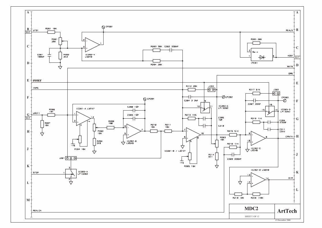
SHEET 3 OF 12
MDC2ArtTech
15 December 2000
A
B
C
D
E
F
G
H
J
K
L
M
A
B
C
D
E
F
G
H
K
L
J
1
510k
3
3
220NF
1 51
X2-5
X2-3
X2-7

SHEET 4 OF 12
MDC2ArtTech
15 December 2000
A
B
C
D
E
F
G
H
J
K
L
M
A
B
C
D
E
F
G
H
K
L
J
X4-30
X4-32
X4-33
X2-7
X3-3
X2-9
X3-5
X3-6
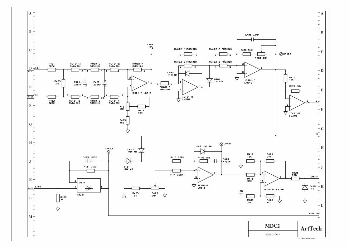
SHEET 5 OF 9
MDC2ArtTech
15 December 2000
A
B
C
D
E
F
G
H
J
K
L
M
A
B
C
D
E
F
G
H
K
L
J
22
22 22 22
22 22 22
1
360k
100NF 680k
X4-1
X4-19
X4-29

SHEET 6 OF 12
MDC2ArtTech
15 December 2000
A
B
C
D
E
F
G
H
J
K
L
M
A
B
C
D
E
F
G
H
K
L
J
X2-9

SHEET 7 OF 12
MDC2ArtTech
15 December 2000
A
B
C
D
E
F
G
H
J
K
L
M
A
B
C
D
E
F
G
H
K
L
J
X4-19
X4-8
X4-7
X4-12
X4-11
X4-16
X4-15
X4-4
X4-6
X4-1

SHEET 8 OF 12
MDC2ArtTech
15 December 2000
A
B
C
D
E
F
G
H
J
K
L
M
A
B
C
D
E
F
G
H
K
L
J
X4-10
X4-7
X4-14
X4-11
X4-18
X4-15
X4-20
X4-22
X4-24
X4-19

SHEET 9 OF 12
MDC2ArtTech
15 December 2000
A
B
C
D
E
F
G
H
J
K
L
M
A
B
C
D
E
F
G
H
K
L
J
OC OS TG EE CP FL
ON RD
X2-9
X2-7
X2-1
X3-11
X3-12

SHEET 10 OF 12
MDC2ArtTech
15 December 2000
A
B
C
D
E
F
G
H
J
K
L
M
A
B
C
D
E
F
G
H
K
L
J
X2-7
X3-9
X3-10
X3-7
X3-8

SHEET 11 OF 12
MDC2ArtTech
15 December 2000
A
B
C
D
E
F
G
H
J
K
L
M
A
B
C
D
E
F
G
H
K
L
J
X4-26
X4-28
X4-25
X4-27
X4-34

SHEET 12 OF 12
MDC2ArtTech
15 December 2000
A
B
C
D
E
F
G
H
J
K
L
M
A
B
C
D
E
F
G
H
K
L
J
X5-5
X5-4
X5-7
X5-6
X5-8
X5-9
X5-10
X5-3
X5-2