Embed Size (px)
Citation preview

Contrac ElectronicsEAS 822, EBS 852, EBS 862
Rack MountingFor Triggering Contrac Modulating Actuators Types PME, LME, RHD and RSD
Operating Instructions 42/68-821EN Rev. 2
(CAD0001)

2
ContentDevice Identification . . . . . . . . . . . . . . . . . . . . . . . . . 3
ID Labels for Electronics EAS 822 + EBS 852 . . . . . . . . . 3ID Label on Electronics EBS 862 . . . . . . . . . . . . . . . . . 3
Safety and Precautions . . . . . . . . . . . . . . . . . . . . . . . 4
Transport and Storage . . . . . . . . . . . . . . . . . . . . . . . 4
Features . . . . . . . . . . . . . . . . . . . . . . . . . . . . . . . . . . 4
General . . . . . . . . . . . . . . . . . . . . . . . . . . . . . . . . . . . 4Mounting . . . . . . . . . . . . . . . . . . . . . . . . . . . . . . . . . 4Design . . . . . . . . . . . . . . . . . . . . . . . . . . . . . . . . . . . 4Labeling . . . . . . . . . . . . . . . . . . . . . . . . . . . . . . . . . . 5
Possible Arrangement in the Mounting Rack . . . . . . 5
Technical Data . . . . . . . . . . . . . . . . . . . . . . . . . . . . . 7Electronics . . . . . . . . . . . . . . . . . . . . . . . . . . . . . . . . 7Mounting Rack . . . . . . . . . . . . . . . . . . . . . . . . . . . . . 7
Actuator Assignment and Cable Cross-Sections . . . 8Rotary Actuators . . . . . . . . . . . . . . . . . . . . . . . . . . . . 8Linear Actuators . . . . . . . . . . . . . . . . . . . . . . . . . . . . 8
Electrical Connection (Standard) . . . . . . . . . . . . . . . 9General . . . . . . . . . . . . . . . . . . . . . . . . . . . . . . . . . . 9EAS 822 . . . . . . . . . . . . . . . . . . . . . . . . . . . . . . . . . 10EBS 852 . . . . . . . . . . . . . . . . . . . . . . . . . . . . . . . . 11EBS 862 . . . . . . . . . . . . . . . . . . . . . . . . . . . . . . . . 11Mounting/Dismounting the Electronics . . . . . . . . . . . . 11Fuses . . . . . . . . . . . . . . . . . . . . . . . . . . . . . . . . . . 13
Operating and Connecting Elements . . . . . . . . . . . 14EAS 822 / EBS 852 . . . . . . . . . . . . . . . . . . . . . . . . . 14EBS 862 . . . . . . . . . . . . . . . . . . . . . . . . . . . . . . . . 15
Construction of the Mounting Rack . . . . . . . . . . . . 16Mains Distribution . . . . . . . . . . . . . . . . . . . . . . . . . . 17
Dimensional Drawings. . . . . . . . . . . . . . . . . . . . . . . 18Mounting Rack . . . . . . . . . . . . . . . . . . . . . . . . . . . . 18EAS 822 . . . . . . . . . . . . . . . . . . . . . . . . . . . . . . . . . 19EBS 852 . . . . . . . . . . . . . . . . . . . . . . . . . . . . . . . . 19EBS 862 . . . . . . . . . . . . . . . . . . . . . . . . . . . . . . . . 20
Setup. . . . . . . . . . . . . . . . . . . . . . . . . . . . . . . . . . . . 21Setup via LCP . . . . . . . . . . . . . . . . . . . . . . . . . . . . . 21Adjustment using the configuration program . . . . . . . . 22Indication at LCP . . . . . . . . . . . . . . . . . . . . . . . . . . . 22
LegendELECTRICAL WARNING
WARNIG
INFORMATION
.An instruction with reference to electrical com-ponents or equipment. It draws attention to therisk of injury or death to persons or damage tothe product, process or surroundings
General instruction that draws attention to therisk of injury or death to persons or damage tothe product, process or surroundings
Further reference for more detailed informationor technical details.

3
1. Device Identification
1.1 ID Labels for Electronics EAS 822 + EBS 852The ID labels of the power electronics are located on topof the units.
1.1.1 ID Label for Hardware Description
1. Electronics type2. Device no./ No. of non-standard version3. Permissible supply voltage range / Year of manufacture4. Permissible frequency range / Max. power dissipation5. Permissible ambient temperature / Protection class6. Information on external fuse
1.0.1 ID Label for Software Description
1 Associated actuator type 2 Number of non-standard version (if required)3 Downloaded software version4 Adjusted force (torque) / Adjusted speed5 Available for customer-specific information
1.1 ID Label on Electronics EBS 862The electronics unit EBS 862 is made up of a base car-rying the ID label for the hardware description, and acover carrying two ID labels for hardware and softwaredescription on its front.
1.1.1 ID Label on the Base (for Hardware Description of the Base)
1. Electronics type2. Device no./ No. of non-standard version3. Permissible supply voltage range / Year of manufacture4. Permissible frequency range / Max. power dissipation5. Permissible ambient temperature / Protection class6. Information on external fuse
1.1.2 ID Label on the Cover (for Hardware Description of the Cover)
1. Device number/ Electronics type2. Device no. / No. of non-standard version3. / Year of manufacture4. Not used5. Permissible ambient temperature / Protection class6. Not used
1.1.3 ID Label on the Cover for the Software Description
1 Associated actuator2 No. of non-standard version (if required)3 Downloaded software version4 Adjusted force (torque) / Adjusted speed5 Available for customer-specific information
1 Elektronik / Electronics Type: ....M
ade
in G
erm
any
2 B-Nr./No. ...... NL
3 U = 230 V ... Jahr/Year
4 f = 50/60 Hz ± 5% Pmax. = ..... W
5 t = ..................°C IP 20 CE6 Ext. Sicherung / Fuse .......
AutomationD-32425 Minden
1 Für Antrieb / For ActuatorContrac . . . . . . . . . . . . . . . . . . . .
2 Mit / NL. Nr./No. . . . . . . . . . . . . .
3 Software Version . . . . . . . . . . . .
4 Eingestellt / adjusted auf/forF=....... .......mm/s
5
ID label
1 Elektronik / Electronics Type: EBS 862
Mad
e in
Ger
man
y
2 B-Nr./No. ...... NL
3 U = 230 V ... Jahr/Year
4 f = 50/60 Hz ± 5% Pmax. = ..... W
5 t = ..................°C IP 20 CE6 Ext. Sicherung / Fuse .......
AutomationD-32425 Minden
1 Elektronik / Electronics Type: ....
Mad
e in
Ger
man
y
2 B. Nr.: NL
3 Jahr/Year
4
5 t = ..................°C IP 20 CE6
AutomationD-32425 Minden
1 Für Antrieb / For ActuatorContrac . . . . . . . . . . . . . . . . . . . .
2 Mit / NL. Nr./No. . . . . . . . . . . . . .
3 Software Version . . . . . . . . . . . .
4 Eingestellt / adjusted auf/forF=....... .......mm/s
5
the front onthe cover
ID labels in
Assembly no.for transformer(interior)

2. Safety and Precautions- Use Contrac power electronics EAS 822, EBS 852, and EBS 862 for driving the
Contrac control actuators specified on the electronics ID label, only.- Prior to maintenance or repair works always disconnect the electronics from mains
and secure the respective control actuator against reactive process forces.- All installation and maintenance works must only be performed by qualified special-
ists who have been trained for these tasks.- Observe the locally valid accident prevention regulations and the regulations con-
cerning works on electrical equipment.
3. Transport and StorageContrac electronics may be stored under moist and aggressive condition for a shorttime. The equipment is protected against external corrosive influences. However, directexposure to rain, snow, etc. must be avoided.Interior areas of the actuator with risk of condensation are protected by desiccant.
Desiccant in electronics: . . . . . . . . . . terminal boxTransport temperature: . . . . . . . . . . . .-30° C … + 80° CStorage temperature: . . . . . . . . . . . . .preferably 0° C … + 40° C
The desiccant guarantees sufficient protection for approximately 150 days. It can beregenerated at a temperature of 90° C within 4 h.The desiccant must be removed prior to commissioning the actuator or the electronics.The mounting rack must only be transported empty and by no means with installedelectronic units.
4. Features- Continuous positioning of Contrac control actuators- Processor-controlled power electronics using the frequency converter principle- Installation in mounting rack in electronics rooms- Protection class IP 20- Power supply 230 V AC or 115 V AC; single-phase- Conventional signal interface (0/4 … 20 mA and binary 24 V)- Digital communication via RS 232 and FSK / HART- Easy installation and commissioning- Simple configuration and parametrization using a configuration program- Adjustable motor torque and speed- Additional functions, e. g. process controller, maintenance manager, programmable
characteristic curve / split range
5. GeneralElectronics of three different sizes are available for the Contrac actuator series. Theelectronics can be adapted to the respective actuator type using special parameters.They are the interfaces between process control systems and actuators/ valves. The actuators / valves are continuously positioned, independent of the input signal type(analog or digital). During positioning the motor torque is continuously changed without steps, until theforces between control actuator and valve are balanced.High positioning accuracy combined with excellent control performance and long life-time are achieved even for changing load situations and short actuation times.
5.1 MountingThe electronics unit is designed for rail-mounting in a special rack providing fourmounting levels. Either four units (EAS 822 and / or EBS 852) or one unit (EBS 862) canbe accommodated on each level. It is also possible to mix the units, as seen in figure 1on page 5. Do not transport the rack with the units installed; the total weight is too high.Mains supply and accommodation of fuse units and junction boxes are as shown in fig-ure 13 on page 17. From there the cable connections are routed to the electronics units.
5.2 Design
5.2.1 ElectronicsThe aluminum cases of the electronics are mounted to four stay bolts on the mountingrails. The units are installed, electrically connected and operated from the front.
4

5.2.2 Mounting RackThe rack is an open steel profile rack. Regarding construction and dimensions it is sim-ilar to commercially available electronics cabinets (e. g. Contronic cabinet).
5.3 LabelingThe mounting racks can be labeled in a headline with approximately 20 characters. Vertically the four levels are designated with letters A, B, C, and D, resulting in a matrixof max. 4 x 4 mounting locations.
6. Possible Arrangement in the Mounting Rack
Fig. 1: Mounting rack with EAS 822 / EBS 852, possiblearrangement
Fig. 2: Mounting rack with EBS 862, possible arrangement
EA
S 8
22
Verteilung / DistributionSicherung / Fuse
Netz / Mains
EA
S 8
22
EA
S 8
22
EA
S 8
22
EA
S 8
22
EA
S 8
22
EA
S 8
22
EA
S 8
22
EB
S 8
52
EB
S 8
52
EB
S 8
52
EB
S 8
52
EB
S 8
52
EB
S 8
52
EB
S 8
52
EB
S 8
52
EBS 862
EBS 862
EBS 862
EBS 862
Ver
teilu
ng /
Dis
trib
utio
nS
iche
rung
/ F
use
Ver
teilu
ng /
Dis
trib
utio
nS
iche
rung
/ F
use
Ver
teilu
ng /
Dis
trib
utio
nS
iche
rung
/ F
use
Ver
teilu
ng /
Dis
trib
utio
nS
iche
rung
/ F
use
Net
z /
Mai
ns
5

Fig. 3: EBS 822 (front view and operating elements similar to EBS 852)
Fig. 4: EBS 862
A01 A02 A03 A04
B01 B02 B03 B04
C01 C02 C03 C04
D01 D02 D03 D04
Table 1: Equipped with EAS 822 / EBS 852 (max. 16 units)
A01 A02 A03 A04
B01 B02 B03 B04
C01 C02 C03 C04
D01
Table 2: Equipped with EAS 822 / EBS 852 / EBS 862
A01
B01
C01
D01
Table 3: Equipped with EBS 862 (max. 4 units)
Commissioning andService Field (CSF)
Terminals for signalinputs and outputs
Terminals formotor connection
Mains connector
(d0111rxa)
Commissioning andService Field (CSF)
Mains connection
Terminals for signalinput and output
Terminals formotor & brake connection (d0113rxa)
6

7. Technical Data7.1 Electronics
1)The 35 A fuse and the thermal safety cutout are included in the scope of delivery. Theyensure safe operation for the special swiching conditions of power electronics EBN861. Note that the cable cross-sectional area between the fuse and the electronicsmust be at least 2.5 mm2.
7.2 Mounting RackWeigth of empty rack: approx. 40 kgWeight of rack with units: approx. 210 kgColor: RAL 7043
Electronics EAS 822 EBS 852 EBS 862
Protection class IP 20Humidity ≤ 75% annual average, no condensation permittedIntake air temperature at mounting rack 0 ... . 45° C
Mounting orientation Vertical, connections from bottom or rightVarnish 2-component epoxy resin (RAL 7032, pebble gray)
Vibration2 … 9 Hz: max. excursion: 3 mm9 … 200 Hz: acceleration: 1 g
Weight approx. 9 kg approx. 11 kg approx. 40 kg
Electrical connectionPower supply via screw terminals,
all other connections via plug-in connection
Cable connection(solid or stranded)
Signal: min 0.52; max. 1.52
Motor: min 0.52; max. 2.52
Mains: min 0.52; max. 4.02
Signal: min 0.52; max. 1.52
Motor: min 0.52; max. 4.02
Mains: min 0.52; max. 4.02
External series fuse 1) 16 A (slow-blow)35 A fuse
16 A thermal safety cutout
Supply voltage 230 V AC (190 V ... 260 V) or
115 V AC (94 V ... 130 V); 50/60 Hz ± 5%; 1 Ph230 V AC (190 V ... 260 V)
50/60 Hz ± 5%; single-phaseAnalog input, set value 0 / 4 … 20 mAAnalog output, actual value 0 / 4 … 20 mA; electrically isolatedOutput; UV 24 VDC; 15 mA for supply of digital inputs
Digital inputs, DI 1 … 3Electrically isolated via opto-couplers
Logical 0: -3V … + 5 V or open; Logical 1: +12 V …+ 35 VDigital outputs, DO 1 … Potential-free relay contact, max. 60 V DC / 25 V AC; 150 mAAnalog input, transmitter Supply and signal input for 2-wire transmitterDigital communication RS 232 for commissioning and service; optionally HART/FSK
Default settings
Function: positionerSet value function: linear, (set value = positioning value)Set value input: 4 … 20 mAActual value output: 4 … 20 mABehavior in 0/100% end position: shut-off with rated force / rated torqueDigital inputs: DI 1 M/A toggle; DI2 / DI3 manual interv. +/-Digital outputs: DO 1 ready; end position signalling 0/100%
Table 4:
7

8. Actuator Assignment and Cable Cross-Sections8.1 Rotary Actuators
8.2 Linear Actuators
1) At rated actuator power; current consumption in positioning mode around 40 ... 50% of Imax.
2) Cable length between electronics and actuator. Cross-sectional area of signal cable0.5mm2.
Electronics
Average power
dissipation of electronics
Max. current consumption1)
Actuator
Cross-sectional area of motor cable /permissible length in [m] 2)
115 V 230 V 1.5 mm2 2.5 mm2 4 mm2 6 mm2 10 mm2
EAS 822 60 W 1.0 A 0.55 A PME 120 180 300 480 - -
EBS 852
60 W 1.8 A 0.90 A RHD 250-10
270 460 - - -
75 W 2.2 A 1.1 A RHD 500-1060 W 3.4 A 1.7 A RHD 800-1080 W 6.0 A 3.0 A RHD 1250-1280 W 4.8 A 2.4 A RHD 2500-2580 W 4.0 A 2.0 A RHD 4000-4080 W 4.0 A 2.0 A RHD 8000-80
EBS 862
80 W -- 5.3 A RHD 2500-10100 W -- 10.0 A RHD 4000-10 160 270 430 - -115 W -- 8.0 A RHD 8000-15
70 120 190 280 460on request -- 12.5 RHD 16000-30
Table 5:
Electronics
Average power
dissipation of electronics
Max. current consumption1)
Actuator
Cross-sectional area of motor cable /permissible length in [m] 2)
115 V 230 V 1.5 mm2 2.5 mm2 4 mm2 6 mm2 10 mm2
EAS 822 60 W 1.0 A 0.55 A LME 620 180 300 480 - -
EBS 852
55 W 3.4 A 1. RSD 10-5.0
270 460 - - -
60 W 3.8 A 1.9 A RSD 10-10.060 W 4.8 A 2.4 A RSD 20-5.075 W 3.8 A 1.9 A RSD 20-7.575 W 4.0 A 2.0 A RSD 50-3.080 W 4.4 A 2.2 A RSD 100-1.580 W 5.0 A 2.5 A RSD 200-0.7
EBS 862100 W -- 6.4 A RSD 50-10.0 160 270 430 - -115 W -- 12.5 A RSD 100-10.0
70 120 190 280 460115 W -- 13.5 A RSD 200-5.0
Table 6:
8

9. Electrical Connection (Standard)The electronics are installed in a mounting rack. They are connected using a 32-pinconnector plug on the actuator side, screw terminals for mains supply and motor cableon the electronics side, and plug connections for the signal cables.
9.1 General
9.1.1 Prerequisite- Disconnection must be possible on mounting site.- All signal cables and the motor cable between actuator and electronics must be
shielded.
9.1.2 Connecting the Shield
Fig. 5:
Disconnect the electronics and the actuator prior to all installation and service works.
- For the cable connections between electronics and actuator, the shield must be ap-plied to both housings.
- For the cable connections between electronics and junction box, the shield must beapplied to the housings of the electronics and of the junction box.
- Remove approximately 2 cm of the cable sheath (1) at the cable entry of the housing(4).
- Open the cable shield (2) in this area and fold it back over the cable sheath (1).- Insert the cable end in the cable entry and fasten it with the clamp; make sure that
the shield folded back makes contact with the clamp and the electronics housing.
1
1
2
4
4
3
3
9

9.2 EAS 822
9.2.1 Wiring Diagram
Fig. 6: Electrical connection of EAS 822
1 Mounting eyelet2 Clamp for strain re-
lief and shield3 Commissioning and
service field (CSF)4 Terminal strip for
signal cable5 Terminal strip for
motor cable6 Mains connection
terminals
1
2
3
4
5
6
BE 1
24V
BE 2 BE 3Uv
30+ - -+
RB
+ -
31
I
U
26 271
+ - + - + - + -
72 83 94 10 135 11 146 12 15L N
U V W Br Br PE 17 18 19 20 21 22 23 24
17 18 19 20 21 22 23 241 2 3 13 14
M3~
Contrac Antrieb / Actuator
Contrac Leistungselektronik / Power Electronics
Schirm beidseitig geerdetscreen grounded at both ends
Motor
Sensoren/Sensors
Han 10 EStecker / Plug
Han 24 EStecker / Plug
SollwertSet Point+ HART
0/4...20mA
IstwertPosition
0/4...20mA
Unterverteilung / Sub Distribution Board
BA 1 BA 2 BA 3
Uv24V
+RB
+ -
28 29
MeßumformerTransmitter4...20mA
7 8
Netz / MainsAC 110 ... 250 VNetz /
Mains
ext. Sicherung /ext. fuse
Heizungca. 6WHeaterapprox. 6 W
(r00350x3)
10
9.3 EBS 852
Fig. 7: Electrical connection of EBS 852
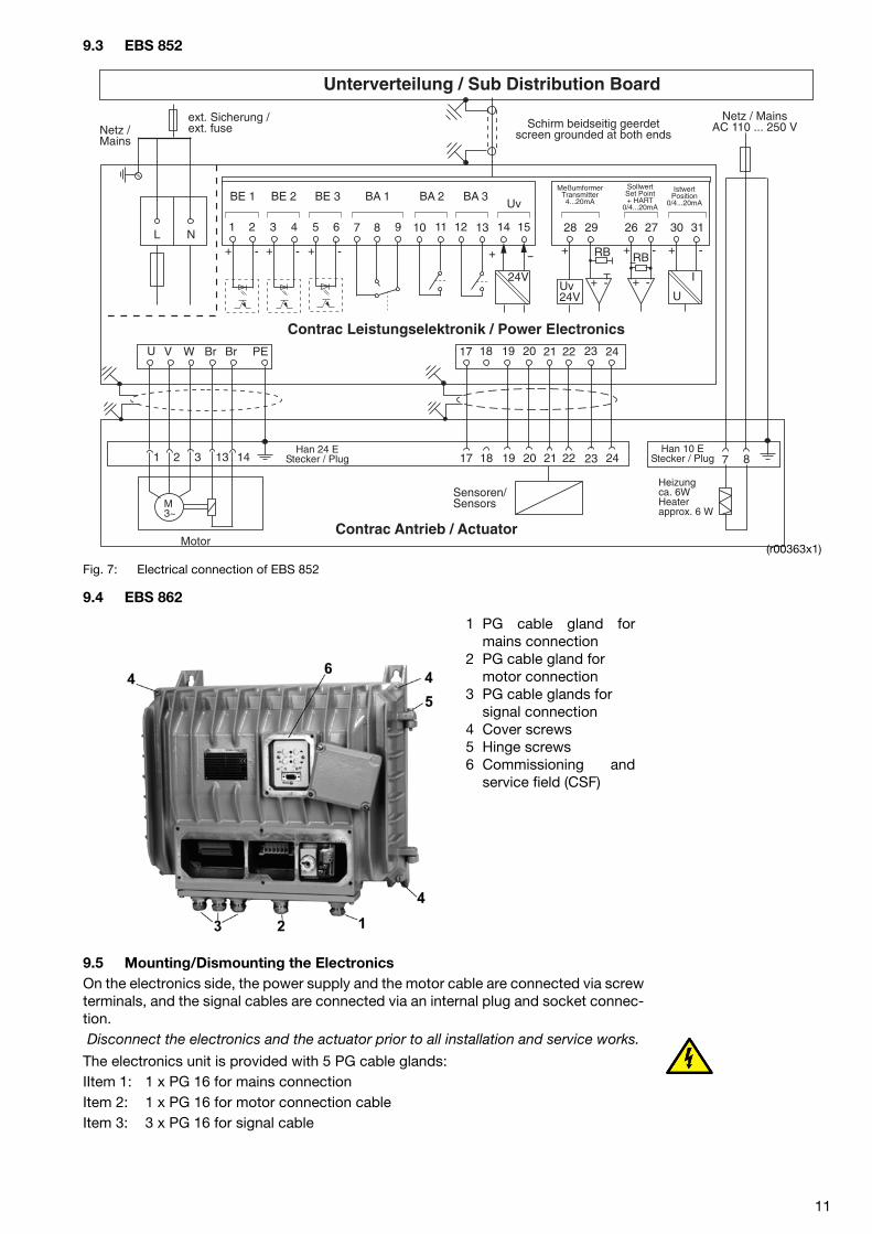
9.4 EBS 862
9.5 Mounting/Dismounting the ElectronicsOn the electronics side, the power supply and the motor cable are connected via screwterminals, and the signal cables are connected via an internal plug and socket connec-tion.Disconnect the electronics and the actuator prior to all installation and service works.
The electronics unit is provided with 5 PG cable glands:IItem 1: 1 x PG 16 for mains connectionItem 2: 1 x PG 16 for motor connection cableItem 3: 3 x PG 16 for signal cable
BE 1
24V
BE 2 BE 3Uv
30+ - -+
RB
+ -
31
I
U
26 271
+ - + - + - + -
72 83 94 10 135 11 146 12 15L N
U V W Br Br PE 17 18 19 20 21 22 23 24
17 18 19 20 21 22 23 241 2 3 13 14
M3~
Contrac Antrieb / Actuator
Contrac Leistungselektronik / Power Electronics
Schirm beidseitig geerdetscreen grounded at both ends
Motor
Sensoren/Sensors
Han 10 EStecker / Plug
Han 24 EStecker / Plug
SollwertSet Point+ HART
0/4...20mA
IstwertPosition
0/4...20mA
Unterverteilung / Sub Distribution Board
BA 1 BA 2 BA 3
Uv24V
+RB
+ -
28 29
MeßumformerTransmitter4...20mA
7 8
Netz / MainsAC 110 ... 250 VNetz /
Mains
ext. Sicherung /ext. fuse
Heizungca. 6WHeaterapprox. 6 W
(r00363x1)
1 PG cable gland formains connection
2 PG cable gland for motor connection
3 PG cable glands for signal connection
4 Cover screws5 Hinge screws6 Commissioning and
service field (CSF)
11

- Undo and remove cover screws (4).- Fold down front part and disconnect internal plug connection between housing
halves.The overall weight of the electronics EBS 862 is approx. 42 kg. For safety reasons it may be neces-sary to install the two housing halves separately
- Undo hinge screw (5).- Lift off front part from hinge bolts towards top.- First, mount rear housing half.- Attach front housing half to hinge bolts, insert screw into top bolt and fasten.- Connect internal plug connection.- Close housing and fasten with cover screws (4).Connect cable according to figure 10 (when applying the shield refer to figure 8 for de-tails).
9.5.1 Wiring Diagram of EBS 862
Fig. 8: Electrical connection of EBS 862
BE 1
24V
BE 2 BE 3Uv
30+ - -+
RB
+ -
31
I
U
26 271
+ - + - + - + -
72 83 94 10 135 11 146 12 15L N
U V W Br Br PE 17 18 19 20 21 22 23 24
10 11 12 14 15 16 18 191 2 3 5 6
M3~
Contrac AntriebContrac Actuator
Contrac Leistungselektronik / Power Electronics
Schirm beidseitig geerdetscreen grounded at both ends
Motor
Han K 8 / 24Einsatz / Plug
SollwertSet Point+ HART
0/4...20mA
IstwertPosition
0/4...20mA
Unterverteilung / Sub Distribution Board
BA 1 BA 2 BA 3
Uv24V
+RB
+ -
28 29
MeßumformerTransmitter4...20mA
7 8
Netz / MainsAC 110 ... 250 V
Netz / Mains AC 230 V
ext. Sicherungenext. fuses
35 A
16 A ( )ϑ
Heizung / heater6 Watt(Option)ro
t / r
ed
wei
ß /
whi
tero
sa /
pink
grau
/gr
eysc
hw./
blac
kbr
aun
/br
own
blau
/bl
ue
Sensoren / Sensors(r00027x1)
12

9.6 Fuses
9.6.1 EAS 822
9.6.2 EBS 852
9.6.3 EBS 862
1) The 35 A fuse and the thermal safety cutout (16 A) are included in the scope of deliv-ery. They ensure safe operation for the special swiching conditions of power electron-ics EBN 861. Note that the cable cross-sectional area between the fuse and theelectronics must be at least 2.5 mm2.
Type Location UV = 115 V UV = 230 V
Series fuse external 16 A; slow-blowMains fuse F1, in terminal box 6.3 A; slow-blow 3.15 A; slow-blowRelay fuse for DO1, DO2, DO3
F2 ... F4; in termi-nal box
3 x 0.2 A; medium time-lag
Table 7:
Type Location UV = 115 V UV = 230 V
Series fuse external 16 A; slow-blowMains fuse F1, in terminal box 12.5 A; slow-
blow10 A; slow-blow
Relay fuse for DO1, DO2, DO3
F2 ... F4; in terminal box
3 x 0,2 A; medium time-lag
Brake fuseon board (power section)
0,315 A; medium time-lag
Intermediate circuit fuse Power board 10 A; super-quick
Table 8:
Type Location UV = 230 V
Series fuse external35 A fuse
16 A thermal safety cutout Relay fuse for DO1, DO2, DO3
F2 ... F4; in terminal box 3 x 0.2 A; medium time-lag
Brake fuse on board (power section) 0.315 A medium time-lagIntermediate circuit fuse power board 15 A; medium time-lag
Table 9:
13

10.Operating and Connecting Elements10.1 EAS 822 / EBS 852
Fig. 9: Position of operating and connecting elements on EAS 822 / EBS 852
F4
F1
F3
F2
RS 232
RESET
Power
WP
100%
0%
OFFSYS INT
ON
(r00345x1)
Commissioningand Service Field(CSF)
Signal
Signal
Signal
Motor
Mains
Terminal
Plu
g
14

10.2 EBS 862
Fig. 10: Position of operating and connecting elements on EBS 862
RS
232
RE
SE
T
Po
wer
WP
100% 0%
OFF
SYS
INT
ON
F2
F3
F4
(r00346x1)
mai
ns c
able
mot
or c
able
sign
al c
able
bor
e fo
rca
ble
gla
nd
Com
mis
sion
ing
and
Ser
vice
Fie
ld(C
SF)
term
inal
s fo
rm
ains
con
nect
ion
plu
g fo
rm
otor
cab
le
plu
g fo
rsi
gnal
cab
le
conn
ectio
n co
nsol
e
15

11.Construction of the Mounting Rack
Fig. 11: Cable routing in mounting rack
(r00347x1)
air guide
cable guide
electronics
electronics
electronics
16

Fig. 12: Cable routing and electronics installation in mounting rack (top view
11.1 Mains Distribution
Fig. 13: Mains distribution for Contrac electronics in mounting rack
Front
max.16 mm 2
N L1 L2 L3PE 4 5 6321 10 11 12987
Ele
ktro
nik
1 /
Ele
ctro
nics
1
21
N N
13 14 15 16
PE PEPENN
16 21 16
17

12.Dimensional Drawings12.1 Mounting Rack
Fig. 14:
100 79
255
210
255
255
210
370
335 40 40
900
386 394
79
2200
80
210
60 135 155
400
100
20
40
35
(r00340x1)
18

12.2 EAS 822
Fig. 15:
12.3 EBS 852
Fig. 16:
283
7
100.5
17 20
40
6240 40
34
79
135
153
20
28
20
8
9
3
9119
,5
313
102
61 20
15
2129
2
255
(r00338x1)
28528,5
15,5
91
312
58 17
25
22
40
9
255
9
79 20
2034
40
4062
28
40
2015
135
153
30
130
5
8710
4119
0
290
99
(r00337x1)
19

12.4 EBS 862
Fig. 17:
386
444
600
(Vor
der
teil
offe
n, 9
0° g
esch
wen
kt /
fro
nt o
pen
)
470
(Sch
wen
krad
ius
/ p
ivot
rad
ius)
100
3535
7597
.5
370
399
30 30
339
262
9
36
20
29
(r00353x1)
20

9. SetupThe basic settings (definition of end positions) can be made via the Local Control Panel(LCP). It is used for adapting the actuator to the operating range and the effective di-rection without a PC. The actuator can be set up and configured completely using theappropriate configuration program.The commissioning and service field is located on the electronics!
9.1 Setup via LCP
9.1.1 Operating elements1. Write-protect switch (Default setting: OFF)2. LED for 100% position Indication if adjustment procedure, saved position, or
fault by different flash frequencies.3. Drive buttons Press to cause drive motion4. Reset button Press to restart processor and clear any 0% and 100%
values.5. Power LED Indicates available mains supply6. RS 232 socket Connection socket to PC7. Potential toggle switch Connection of reference potential to the system or pro-
tective earth (by default set to system)8. LED for 0% position Indication if adjustment procedure, saved position, or
fault by different flash frequencies..9. Accept button (0%) Press to define current position as 0%; simultaneously
press push button 11 to complete the adjustment proce-dure.
10. Accept button (100%) Press to define current position as 100%; simultaneouslypress push button 10 to complete the adjustment proce-dure
Figure 15: Local Control Panel (LCP)
The actuator range is not preset in factory!
9.1.2 Initial situation- Electronics connected to power supply and actuator- Write-protect switch (1) set to “OFF” position- Electronics in operating mode “MAN” (no signal on DI 1)- No fault (if a fault occurs, both LEDs flash alternately at 4 Hz)
9.1.3 Setup procedure- Undo the screws of the LCP cover- Swing the cover to the side
1
2
3
4
5
6
78
9
10
(r0110rxa)
14

9.1.3.1 “Setting” mode- Set electronics to “setting” mode by pressing both push buttons (3) simultaneously
for approx. 5 seconds, until both LEDs (2 + 8) are flashing synchronously at approx.4Hz.
9.1.3.2 Defining first position (0% or 100%) (Higher precision in 2ndposition)
- Move to desired position by pressing one push button (3).- To accept the position, press push button (10) or (9); the associated LED flashes at
approx. 1Hz when value is correctly accepted, the other continues to flash atapprox. 4Hz
9.1.3.3 Defining second position (0% or 100%)- Move to second position by pressing one push button (3).- To accept the position, press push button (10) or (9); both LEDs (2) and (8) are flash-
ing at approx. 1Hz when value is accepted correctly.
9.1.3.4 Saving the settings- The settings are accepted by simultaneously pressing the push buttons (10 + 9); the
LEDs (2 + 8) extinguish after a short time, and the adjustment procedure is complet-ed.
- If the selected range is too small for the actuator, both LEDs will flash again at 4Hz.Repeat the adjustment procedure a larger value (min. positioning travel).(See positioning travel specification on actuator ID label)
9.1.3.5 Correction after setup- If the setting is to be corrected after accepting the first value, first press the Reset
button (4) and then repeat the setting.- If the correction is to be done after saving the settings, the entire adjustment proce-
dure must be repeated.
9.2 Adjustment using the configuration programContext-sensitive help information is available in the configuration program at all times.For basic handling and installation instructions refer to the associated manual, number41/68-001.A conductive ground connection is established between the PC and the CONTRACelectronics with the RS 232 communication cable. If the PC is grounded, this may causea ground loop in the installation.
9.3 Indication at LCPFunction Indication
AdjustmentChange-over to adjustment mode:Press and hold both drive switches for approx. 5 seconds
Both LEDs flash synchronously at approx 4Hz after time has expired.
Moving to an end positionUse respective drive button on CSF
Both LEDs continue to flash at 4Hz while driving.
Saving the first end positionPress button 0% or 100%
The associated LED flashes at approx. 1Hz, the other continues at 4Hz.
Saving the second end positionPress button 0% or 100%
The associated LED flashes at approx. 1Hz synchronously to the first one.
Terminate adjustmentPress 0% and 100% buttons simulta-neously
Both LEDs are briefly lit together and then extinguish.
OperationNormal operation: MAN / AUT LED offDriving with button on CSFPriority over control system
LED off
Fault (both LEDs flash alternately at 4Hz)Reset:Resets fault indications
If no other fault conditions exist, both LEDs extinguish.
Reset if operating range is exceeded;press and hold both drive button for 5 sec-onds, then press Reset button
After approx. 5 seconds the flash rhythm is briefly interrupted. After “Reset” the electronics switch to adjustment mode.
Table 6:
15

Subject to technical changes.
This technical documentation is protected by copyright law. Do not translate, copy or distribute in any way - even in a modified form oras an excerpt - without the prior written permission of the right-holder. Also, reprints, photomechanical or electronical reproduction orstorage of data in data processing systems or data networks must be authorized by the right-holder. Any infringement of the copyrightlaw will be prosecuted.
Subject to technical changesPrinted in the Fed. Rep. of Germany
42/68-821 EN 03. 03
ABB Automation Products GmbHSchillerstraße 72D - 32425 MindenDEUTSCHLANDTel. +49 571 830 - 1494Fax +49 571 830 - 1860http://www.abb.de
ABB Inc.125 E. County Line RoadWarminster, PA 18974USATel. +1 215 674 6000Fax +1 215 674 7183http://www.abb.com
ABB Ltd.Salterbeck Trading EstateWorkington, CumbriaCA14 5DSUKTel. +44 (0)1946 830 611Fax. +44 (0)1946 830 611http://www.abb.com