Embed Size (px)
Citation preview
Contribution to Numerical Modelling of Concrete- Masonry Interface In Concrete Framed Structures
With Masonry Infill
Induprabha S.A.D,
B.Sc.Eng.(Hons)(Moratuwa)
(email: [email protected])
K.G.S. Dilrukshi,
B.Sc. Eng (Moratuwa), Ph.D. (Moratuwa),
(email: [email protected])
Abstract
Masonry infills have long been used as interior partitions and exterior walls in buildings. They
are usually treated as non-structural elements, and their interaction with the bounding frame is
often ignored in design. Nevertheless, infill contributes strength to a structure and will interact
with the bounding frame when the structure is subjected to strong lateral seismic loads, when
the infill is stressed due to movements of an overlying slab or any other case of in-plane or out
of plane lateral loading. This interaction may or may not be beneficial to the performance of the
structure, however, and it has been a topic of much debate in the last few decades. The
interaction of the infill is governed by the relative stiffness and strength characteristics of each
individual component and most importantly the interface characteristics that decide the degree
of composite action.
An interface is a special contact plane on which nonlinear relations between stresses and
displacement discontinuities are present. Very often initiation and propagation of cracks along
these interfaces are the cause of failure of the relevant structures. Similarly, in the case of
concrete framed masonry assemblages, the bond between the masonry and the concrete frame is
a weak link, through which failure is possible. Therefore to simulate this behaviour, interface
elements with a suitable constitutive model can be utilized.
This paper explores finite element models developed to simulate the behaviour of concrete-
masonry interface of masonry infill. In this study, brick-concrete couplets were mathematically
modelled, using commercially available software ANSYS. The adopted numerical strategy
consists of simplifying the concrete-masonry-mortar interface to a zero thick interface,
modelling the brick units and the concrete units with three dimensional solid brick elements and
modelling the bond using zero thickness interface elements with a cohesive-zone model (CZM)
for mixed-mode fracture based on damage mechanics introduced by Alfano and Crisfield(2001).
Key words
Displacement discontinuities, cohesive-zone model, zero thick interface, numerical modelling of masonry, non-linear behaviour.
1. Introduction
Masonry infills have long been used as interior partitions and exterior walls in buildings. They
are usually treated as non-structural elements, and their interaction with the bounding frame is
often ignored in design. Nevertheless, infill contributes strength to a structure and will interact
with the bounding frame when the structure is subjected to strong lateral seismic loads, when
the infill is stressed due to movements of an overlying slab or any other case of induced in-plane
or out of plane lateral stresses. This interaction may or may not be beneficial to the performance
of the structure, however, and it has been a topic of much debate in the last few decades. The
performance of such frame structures with infill, during an earthquake has attracted major
attention. Even though frame–infill interaction has sometimes led to undesired structural
performance, recent studies have shown that a properly designed infilled frame can be superior
to a bare frame in terms of stiffness, strength, and energy dissipation. Similarly, in the case of
infill cracking due to thermal movements of an overlying slab which is a common problem in a
tropical country like Sri Lanka the interaction between concrete beam and masonry wall plays a
major role.
According to Ghassan K (2008), experimental investigations of the behavior of masonry-infilled
steel and reinforced concrete frames under in-plane and out of plane lateral loading has been the
subject of many researchers. Starting back in 1970 with the experimental studies of Fiorato et al
who tested 1/8-scale non-ductile reinforced concrete as cyclic lateral loading the investigations
were followed by the studies of many other researchers like Klingner and Bertero in 1976,
Bertero and Brokken in 1983, Zarnic and Tomazevic in 1985, and Schmidt in 1989. More
recently, single-story reinforced concrete frames with masonry infills were studied by Mehrabi
et al in 1994 and 1997, Angel et al in 1994, and Al-Chaar et al in 1998 and 2002. Masonry
infilled steel frames were tested by Dkanasekar et al in 1985, Dawe and Seah in 1989, Mander
et al in 1993, and many others.
All experimental studies cited above have shown that the behavior of an infilled frame is
heavily influenced by the interaction of the infill with its bounding frame. In most instances, the
lateral resistance of an infilled frame is not equal to a simple sum of the resistance of its
components because frame/infill interaction can alter the load-resisting mechanisms of the
individual components. At low lateral loading, an infilled frame acts as a monolithic load
resisting system and as loading increases, the infill tends to partially separate from the bounding
frame. Due to this a compression strut mechanism is formed, as observed in many earlier
studies.
Due to the presence of a vast range of geometrical and structural configurations of masonry, use
of physical models to investigate masonry is costly and difficult. As a result finite element
method (FEM) has been widely used in the analysis of concrete and steel framed masonry
structures. A number of different analytical models have been developed to evaluate these
infills. Dhanasekar and Page (1986) and Liauw and Lo (1988) have used linear and nonlinear
beam elements to model the behaviour of steel frames, and interface elements to model the
interaction between the infill and the frame. Dhanasekar and Page used a nonlinear orthotropic
model to simulate the behaviour of brick infills, and Liauw and Lo used a simple smeared crack
model to simulate the behavior of micro-concrete infills. Schmidt (1989) used smeared crack
elements to model both reinforced concrete frames and brick infills. In all those analyses, infill
panels have been modelled as a homogenous material before fracture, and the effects of mortar
joints have been smeared out. These models for concrete-masonry framed structures have a
major deficiency of sufficient attention not being paid to simulate the interaction through the
concrete beam and masonry infill junction.
Further in Engineering practice some of the commonly used interface types at the beam wall
junction include (i) leaving a gap between the frame and the infill in order to avoid transfer of
load between frame and infill (ii) breaking of bond between frame and infill (no bond/non
integral) (iii) connecting the frame and the infill by provision of shear connectors (integral
interface) (iv) connecting the frame and the infill by cement mortar (conventional type) and (v)
using of non-structural materials like lead sheet, cork etc. Therefore a numerical approach has to
be adopted to simulate the concrete masonry infill interface behaviour and to explore the effect
of bond between concrete and masonry infill on the global behaviour of these framed structures.
An interface is a special contact plane on which nonlinear relations between stresses and
displacement discontinuities are present. Therefore to simulate this behaviour interface elements
with a suitable constitutive model can be utilized and essentially this should be verified with
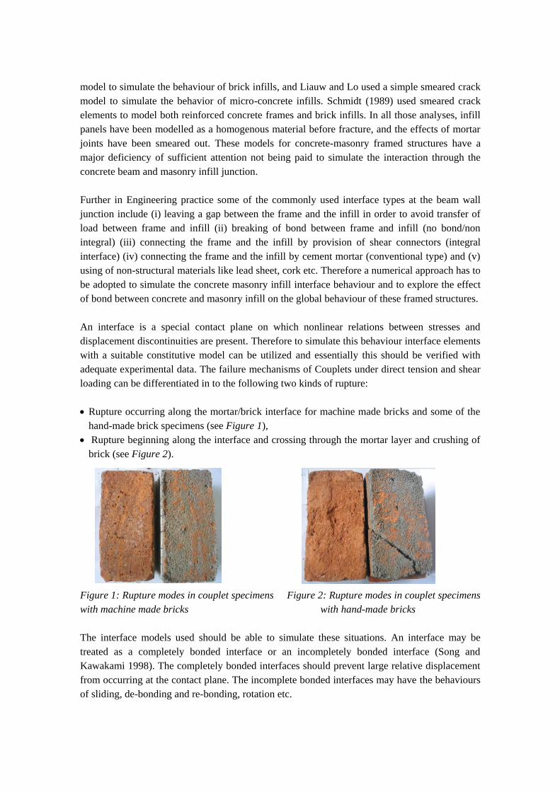
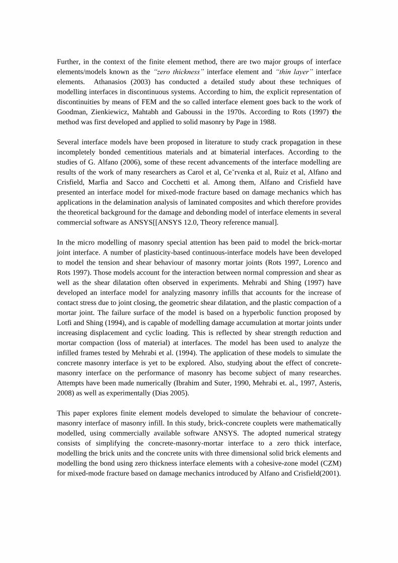
adequate experimental data. The failure mechanisms of Couplets under direct tension and shear
loading can be differentiated in to the following two kinds of rupture:
Rupture occurring along the mortar/brick interface for machine made bricks and some of the
hand-made brick specimens (see Figure 1),
Rupture beginning along the interface and crossing through the mortar layer and crushing of
brick (see Figure 2).
Figure 1: Rupture modes in couplet specimens Figure 2: Rupture modes in couplet specimens
with machine made bricks with hand-made bricks
The interface models used should be able to simulate these situations. An interface may be
treated as a completely bonded interface or an incompletely bonded interface (Song and
Kawakami 1998). The completely bonded interfaces should prevent large relative displacement
from occurring at the contact plane. The incomplete bonded interfaces may have the behaviours
of sliding, de-bonding and re-bonding, rotation etc.
Further, in the context of the finite element method, there are two major groups of interface
elements/models known as the “zero thickness” interface element and “thin layer” interface
elements. Athanasios (2003) has conducted a detailed study about these techniques of
modelling interfaces in discontinuous systems. According to him, the explicit representation of
discontinuities by means of FEM and the so called interface element goes back to the work of
Goodman, Zienkiewicz, Mahtabh and Gaboussi in the 1970s. According to Rots (1997) the
method was first developed and applied to solid masonry by Page in 1988.
Several interface models have been proposed in literature to study crack propagation in these
incompletely bonded cementitious materials and at bimaterial interfaces. According to the
studies of G. Alfano (2006), some of these recent advancements of the interface modelling are
results of the work of many researchers as Carol et al, Ce˘rvenka et al, Ruiz et al, Alfano and
Crisfield, Marfia and Sacco and Cocchetti et al. Among them, Alfano and Crisfield have
presented an interface model for mixed-mode fracture based on damage mechanics which has
applications in the delamination analysis of laminated composites and which therefore provides
the theoretical background for the damage and debonding model of interface elements in several
commercial software as ANSYS[[ANSYS 12.0, Theory reference manual].
In the micro modelling of masonry special attention has been paid to model the brick-mortar
joint interface. A number of plasticity-based continuous-interface models have been developed
to model the tension and shear behaviour of masonry mortar joints (Rots 1997, Lorenco and
Rots 1997). Those models account for the interaction between normal compression and shear as
well as the shear dilatation often observed in experiments. Mehrabi and Shing (1997) have
developed an interface model for analyzing masonry infills that accounts for the increase of
contact stress due to joint closing, the geometric shear dilatation, and the plastic compaction of a
mortar joint. The failure surface of the model is based on a hyperbolic function proposed by
Lotfi and Shing (1994), and is capable of modelling damage accumulation at mortar joints under
increasing displacement and cyclic loading. This is reflected by shear strength reduction and
mortar compaction (loss of material) at interfaces. The model has been used to analyze the
infilled frames tested by Mehrabi et al. (1994). The application of these models to simulate the
concrete masonry interface is yet to be explored. Also, studying about the effect of concrete-
masonry interface on the performance of masonry has become subject of many researches.
Attempts have been made numerically (Ibrahim and Suter, 1990, Mehrabi et. al., 1997, Asteris,
2008) as well as experimentally (Dias 2005).
This paper explores finite element models developed to simulate the behaviour of concrete-
masonry interface of masonry infill. In this study, brick-concrete couplets were mathematically
modelled, using commercially available software ANSYS. The adopted numerical strategy
consists of simplifying the concrete-masonry-mortar interface to a zero thick interface,
modelling the brick units and the concrete units with three dimensional solid brick elements and
modelling the bond using zero thickness interface elements with a cohesive-zone model (CZM)
for mixed-mode fracture based on damage mechanics introduced by Alfano and Crisfield(2001).
2. Methodology
2.1 Modelling assumptions and the numerical models used in the study
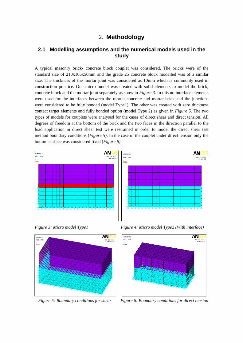
A typical masonry brick- concrete block couplet was considered. The bricks were of the
standard size of 210x105x50mm and the grade 25 concrete block modelled was of a similar
size. The thickness of the mortar joint was considered as 10mm which is commonly used in
construction practice. One micro model was created with solid elements to model the brick,
concrete block and the mortar joint separately as show in Figure 3. In this no interface elements
were used for the interfaces between the mortar-concrete and mortar-brick and the junctions
were considered to be fully bonded (model Type1). The other was created with zero thickness
contact target elements and fully bonded option (model Type 2) as given in Figure 5. The two
types of models for couplets were analysed for the cases of direct shear and direct tension. All
degrees of freedom at the bottom of the brick and the two faces in the direction parallel to the
load application in direct shear test were restrained in order to model the direct shear test
method boundary conditions (Figure 5). In the case of the couplet under direct tension only the
bottom surface was considered fixed (Figure 6).
Figure 3: Micro model Type1 Figure 4: Micro model Type2 (With interface)
Figure 5: Boundary conditions for shear Figure 6: Boundary conditions for direct tension
2.2 Numerical modelling of cracking
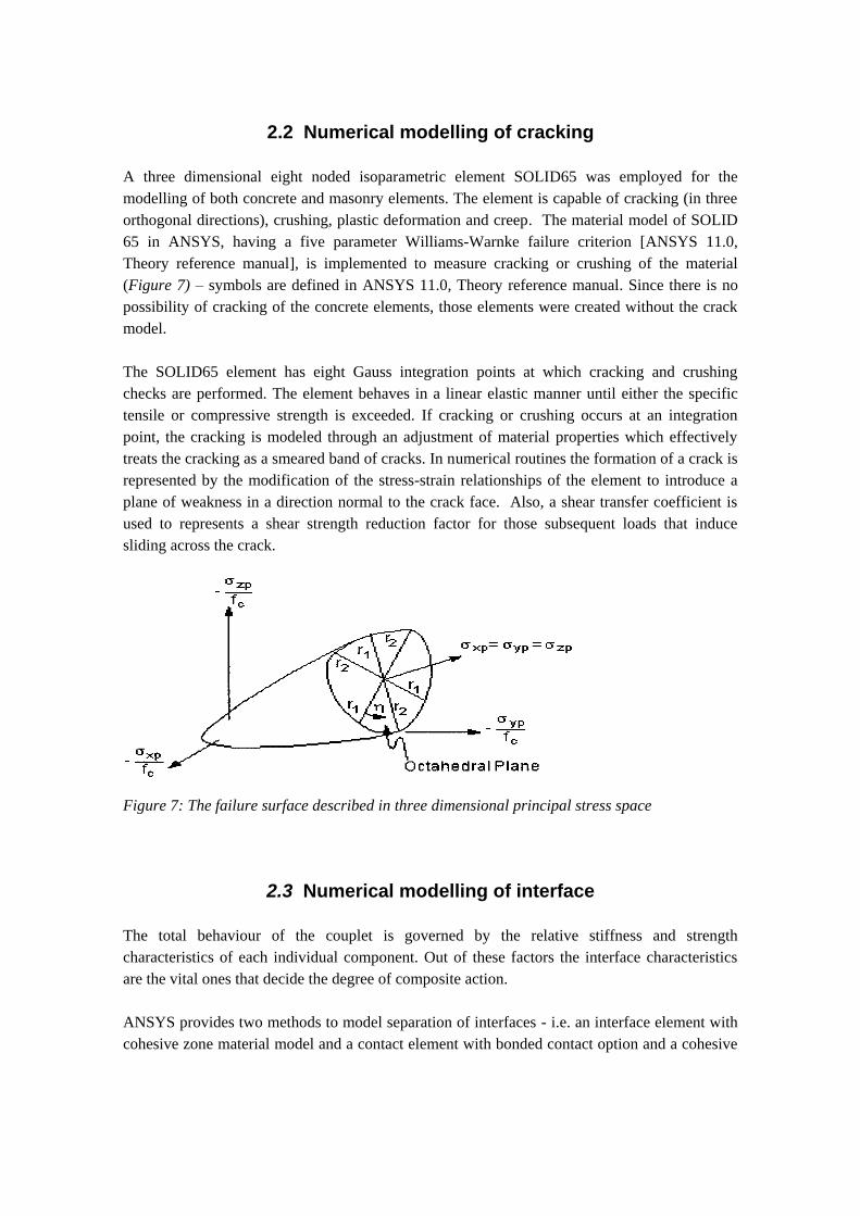
A three dimensional eight noded isoparametric element SOLID65 was employed for the
modelling of both concrete and masonry elements. The element is capable of cracking (in three
orthogonal directions), crushing, plastic deformation and creep. The material model of SOLID
65 in ANSYS, having a five parameter Williams-Warnke failure criterion [ANSYS 11.0,
Theory reference manual], is implemented to measure cracking or crushing of the material
(Figure 7) – symbols are defined in ANSYS 11.0, Theory reference manual. Since there is no
possibility of cracking of the concrete elements, those elements were created without the crack
model.
The SOLID65 element has eight Gauss integration points at which cracking and crushing
checks are performed. The element behaves in a linear elastic manner until either the specific
tensile or compressive strength is exceeded. If cracking or crushing occurs at an integration
point, the cracking is modeled through an adjustment of material properties which effectively
treats the cracking as a smeared band of cracks. In numerical routines the formation of a crack is
represented by the modification of the stress-strain relationships of the element to introduce a
plane of weakness in a direction normal to the crack face. Also, a shear transfer coefficient is
used to represents a shear strength reduction factor for those subsequent loads that induce
sliding across the crack.
Figure 7: The failure surface described in three dimensional principal stress space
2.3 Numerical modelling of interface
The total behaviour of the couplet is governed by the relative stiffness and strength
characteristics of each individual component. Out of these factors the interface characteristics
are the vital ones that decide the degree of composite action.
ANSYS provides two methods to model separation of interfaces - i.e. an interface element with
cohesive zone material model and a contact element with bonded contact option and a cohesive
zone material (ANSYS 11.0, Contact technology guide). In this study contact element with
bonded contact option and a cohesive zone material was used to model interface.
For the modelling of the masonry-concrete interface, the surface to surface contact element of
“CONTAC173” with target element “TARGE170” was used. ANSYS provides two cohesive
zone material models with bilinear behaviour to represent debonding. The material behaviour,
defined in terms of contact stresses (normal and tangential) and contact separation distance
(normal gap and tangential sliding), is characterized by linear elastic loading followed by linear
softening. Debonding allows three modes of separation;
1. Mode I debonding for normal separation
2. Mode II debonding for tangential separation
3. Mixed mode debonding for normal and tangential separation.
Debonding is also characterized by convergence difficulties during material softening.
Artificial damping is provided to overcome these problems. After debonding is completed, the
surface interaction is governed by standard contact constraints for normal and tangential
directions. The cohesive zone material model with bilinear behaviour is defined as:
dUKP nn 1 , dUK yty 1 and dUK ztz 1
where; P- Normal contact stress (tension), τy - tangential contact stress in Y direction, τz -
tangential contact stress in Z direction, Kn - Normal contact stiffness, Kt - Tangential contact
stiffness, Un - Contact gap, Uy - Contact slip distance in Y direction, Uz -Contact slip distance in
Z direction, d - Debonding parameter.
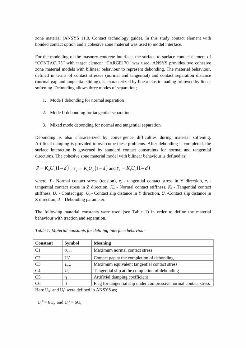
The following material constants were used (see Table 1) in order to define the material
behaviour with traction and separation.
Table 1: Material constants for defining interface behaviour
Constant Symbol Meaning
C1 σmax Maximum normal contact stress
C2 Unc Contact gap at the completion of debonding
C3 τmax Maximum equivalent tangential contact stress
C4 Utc Tangential slip at the completion of debonding
C5 η Artificial damping coefficient
C6 β Flag for tangential slip under compressive normal contact stress
Here Unc and Ut
c were defined in ANSYS as;
Unc = 6Un and Ut
c = 6Ut.
For brittle materials like concrete, Un and Ut are the displacements corresponding to σmax and
τmax respectively. The values for Kn, Kt, σmax and τmax were the same as the values defined earlier
in this chapter. The values of η and β were defined according to the instructions of ANSYS
manual as;
η = 1000 x modulus of elasticity and β = 0
2.4 Simplification of concrete beam masonry infill junction in to a zero thickness interface
The method developed by Rots (1997) to model the masonry-mortar interface was used in this
study to model the concrete–masonry interface. In this model the constitutive behaviour of the
unit is described by stress-strain relations for the continuum element. In the linear elastic range,
the stress (σ) vs the strain (ε) relationship can be described according to Hooke’s law. The
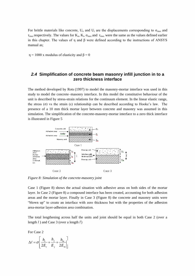
presence of a 10 mm thick mortar layer between concrete and masonry was assumed in this
simulation. The simplification of the concrete-masonry-mortar interface to a zero thick interface
is illustrated in Figure 5
Figure 8: Simulation of the concrete-masonry joint
Case 1 (Figure 8) shows the actual situation with adhesive areas on both sides of the mortar
layer. In Case 2 (Figure 8) a compound interface has been created, accounting for both adhesion
areas and the mortar layer. Finally in Case 3 (Figure 8) the concrete and masonry units were
“blown up” to create an interface with zero thickness but with the properties of the adhesion
area-mortar layer-adhesion area combination.
The total lengthening across half the units and joint should be equal in both Case 2 (over a
length l ) and Case 3 (over a length l/)
For Case 2
m
m
j
j
c
c
E
h
E
h
E
h
22
where hc, hm and hj are the thicknesses and Ec, Em and Ej are the moduli of elasticity of the
concrete, masonry and joint respectively.
For Case 3 (the simplified model)
m
m
nc
c
E
h
kE
h/
/
/
//
2
1
2
however, Δl should be equal to Δl/ and we have also assumed that blown up units have the same
E value as the real units (i.e cc EE / and Em = Em/ )
Also, 2
/ j
mm
hhh and
2
/ j
cc
hhh
Therefore the normal stiffness, kn, of the interface element will become:
jcjmmcj
mjc
nEEEEEEh
EEEk
4
4
Similarly the shear stiffness, kt, of the interface element is given by:
jcjmmcj
mjc
tGGGGGGh
GGGk
4
4
where
12
EG
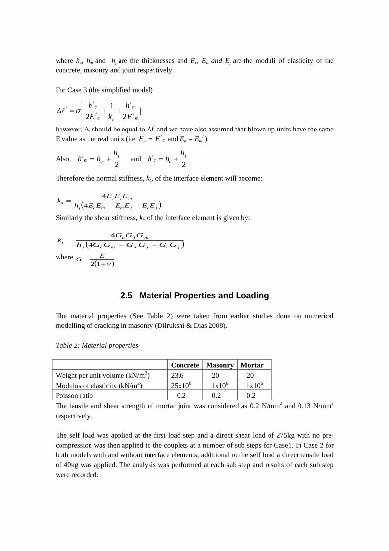
2.5 Material Properties and Loading
The material properties (See Table 2) were taken from earlier studies done on numerical
modelling of cracking in masonry (Dilrukshi & Dias 2008).
Table 2: Material properties
Concrete Masonry Mortar
Weight per unit volume (kN/m3) 23.6 20 20
Modulus of elasticity (kN/m2) 25x106 1x10⁶ 1x10⁶
Poisson ratio 0.2 0.2 0.2
The tensile and shear strength of mortar joint was considered as 0.2 N/mm2 and 0.13 N/mm2
respectively.
The self load was applied at the first load step and a direct shear load of 275kg with no pre-
compression was then applied to the couplets at a number of sub steps for Case1. In Case 2 for
both models with and without interface elements, additional to the self load a direct tensile load
of 40kg was applied. The analysis was performed at each sub step and results of each sub step
were recorded.
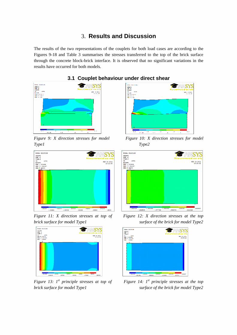
3. Results and Discussion
The results of the two representations of the couplets for both load cases are according to the
Figures 9-18 and Table 3 summarises the stresses transferred to the top of the brick surface
through the concrete block-brick interface. It is observed that no significant variations in the
results have occurred for both models.
3.1 Couplet behaviour under direct shear
Figure 9: X direction stresses for model Figure 10: X direction stresses for model
Type1 Type2
Figure 11: X direction stresses at top of Figure 12: X direction stresses at the top
brick surface for model Type1 surface of the brick for model Type2
Figure 13: 1st principle stresses at top of Figure 14: 1st principle stresses at the top
brick surface for model Type1 surface of the brick for model Type2
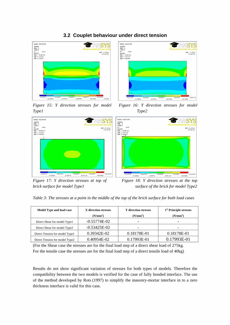
3.2 Couplet behaviour under direct tension
Figure 15: Y direction stresses for model Figure 16: Y direction stresses for model
Type1 Type2
Figure 17: Y direction stresses at top of Figure 18: Y direction stresses at the top
brick surface for model Type1 surface of the brick for model Type2
Table 3: The stresses at a point in the middle of the top of the brick surface for both load cases
Model Type and load case X direction stresses
(N/mm2)
Y direction stresses
(N/mm2)
1st Principle stresses
(N/mm2)
Direct Shear for model Type1 -0.55774E-02 - -
Direct Shear for model Type2 -0.53425E-02 - -
Direct Tension for model Type1 0.39342E-02 0.18178E-01 0.18178E-01
Direct Tension for model Type2 0.40954E-02 0.17993E-01 0.17993E-01
(For the Shear case the stresses are for the final load step of a direct shear load of 275kg.
For the tensile case the stresses are for the final load step of a direct tensile load of 40kg)
Results do not show significant variation of stresses for both types of models. Therefore the
compatibility between the two models is verified for the case of fully bonded interface. The use
of the method developed by Rots (1997) to simplify the masonry-mortar interface in to a zero
thickness interface is valid for this case.
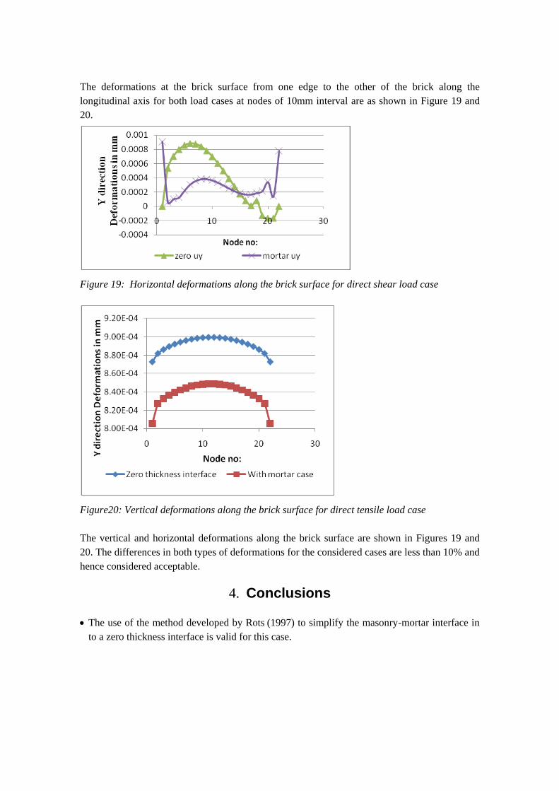
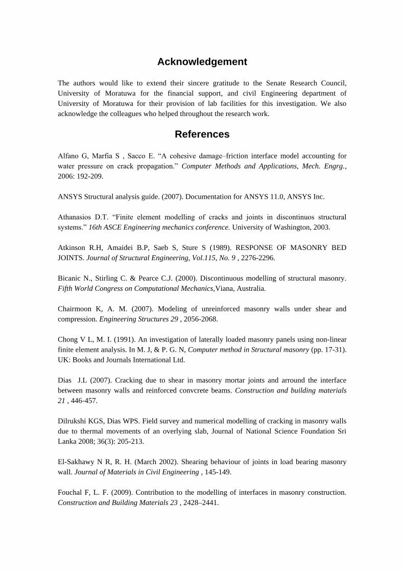
The deformations at the brick surface from one edge to the other of the brick along the
longitudinal axis for both load cases at nodes of 10mm interval are as shown in Figure 19 and
20.
Figure 19: Horizontal deformations along the brick surface for direct shear load case
Figure20: Vertical deformations along the brick surface for direct tensile load case
The vertical and horizontal deformations along the brick surface are shown in Figures 19 and
20. The differences in both types of deformations for the considered cases are less than 10% and
hence considered acceptable.
4. Conclusions
The use of the method developed by Rots (1997) to simplify the masonry-mortar interface in
to a zero thickness interface is valid for this case.
Acknowledgement
The authors would like to extend their sincere gratitude to the Senate Research Council,
University of Moratuwa for the financial support, and civil Engineering department of
University of Moratuwa for their provision of lab facilities for this investigation. We also
acknowledge the colleagues who helped throughout the research work.
References
Alfano G, Marfia S , Sacco E. “A cohesive damage–friction interface model accounting for
water pressure on crack propagation.” Computer Methods and Applications, Mech. Engrg.,
2006: 192-209.
ANSYS Structural analysis guide. (2007). Documentation for ANSYS 11.0, ANSYS Inc.
Athanasios D.T. “Finite element modelling of cracks and joints in discontinuos structural
systems.” 16th ASCE Engineering mechanics conference. University of Washington, 2003.
Atkinson R.H, Amaidei B.P, Saeb S, Sture S (1989). RESPONSE OF MASONRY BED
JOINTS. Journal of Structural Engineering, Vol.115, No. 9 , 2276-2296.
Bicanic N., Stirling C. & Pearce C.J. (2000). Discontinuous modelling of structural masonry.
Fifth World Congress on Computational Mechanics,Viana, Australia.
Chairmoon K, A. M. (2007). Modeling of unreinforced masonry walls under shear and
compression. Engineering Structures 29 , 2056-2068.
Chong V L, M. I. (1991). An investigation of laterally loaded masonry panels using non-linear
finite element analysis. In M. J, & P. G. N, Computer method in Structural masonry (pp. 17-31).
UK: Books and Journals International Ltd.
Dias J.L (2007). Cracking due to shear in masonry mortar joints and arround the interface
between masonry walls and reinforced convcrete beams. Construction and building materials
21 , 446-457.
Dilrukshi KGS, Dias WPS. Field survey and numerical modelling of cracking in masonry walls
due to thermal movements of an overlying slab, Journal of National Science Foundation Sri
Lanka 2008; 36(3): 205-213.
El-Sakhawy N R, R. H. (March 2002). Shearing behaviour of joints in load bearing masonry
wall. Journal of Materials in Civil Engineering , 145-149.
Fouchal F, L. F. (2009). Contribution to the modelling of interfaces in masonry construction.
Construction and Building Materials 23 , 2428–2441.
Ghassan K, Al-Chaar, Mrhrabi A. (March 2008). Constitutive Models for Nonlinear Finite
Element Analysis of Masonry Prisms and Infill Walls. Champaign: Construction Engineering
Research Laboratory, U.S. Army Engineer Research and Development Center.
Guinea G.V., Hussein G., Elices M. & Planas J. (2000). Micromechanical modelling of brick-
masonry fracture. Cement and Concrete Research, Volume 30, pp731-737.
Ibrahim KS, Suter GT. “Finite element study of thermal stresses in low rise concrete masonry
walls.” Fifth North American Masonry Conference. Urbana-champaign: University of Illinois,
1990.
Lourenco P.B. (1997). An anisotropic macro-model for masonry plates and shells:
Implementation and validation. Research report, TNO Building and Construction Research,
Delft University of Technology.
Lourenco PB, Rots JG. “Multisurface interface model for analysis of masonry structures.”
Journal of Engineering mechanics, 1997: 660-668.
Lourenco P.B. (1998). Sensitivity analysis of masonry structures. Proceedings of 8th Canadian
Symposium, Jasper, Canada.
Madan A, R. A. (October 1997). Modeling of masonry infill panels for structural analysis.
Journal of Structural Engineering , 1295-1302.
Mark J.M., Peter W.K. & Robert E.M. (2004). Modelling soil/structure interaction for masonry
structures. Journal of Structural Engineering. Volume 130, pp 641-649.
Rots J.G. (1991). Computer simulation of masonry fracture: continuum and discontinuum
models. Computer Methods in Structural Masonry (Eds. Middleton J. and Pande G.N.), pp. 114-
123, Books and Journals International Ltd., UK.
Rots J.G. (1997). Numerical models in Diana. In: Structural masonry – an
experimental/numerical basis for practical design rules. (Eds. Rots J.G.) pp.46-95, A.A. Balkem
publishers, Rotterdam, Netherlands