Embed Size (px)
Citation preview

Louisiana State UniversityLSU Digital Commons
LSU Historical Dissertations and Theses Graduate School
1986
Contribution to Power System Harmonic Analysis.Yahia BaghzouzLouisiana State University and Agricultural & Mechanical College
Follow this and additional works at: https://digitalcommons.lsu.edu/gradschool_disstheses
This Dissertation is brought to you for free and open access by the Graduate School at LSU Digital Commons. It has been accepted for inclusion inLSU Historical Dissertations and Theses by an authorized administrator of LSU Digital Commons. For more information, please [email protected].
Recommended CitationBaghzouz, Yahia, "Contribution to Power System Harmonic Analysis." (1986). LSU Historical Dissertations and Theses. 4218.https://digitalcommons.lsu.edu/gradschool_disstheses/4218

INFORMATION TO USERS
This reproduction was made from a copy of a manuscript sent to us for publication and microfilming. While the m ost advanced technology has been used to photograph and reproduce this manuscript, the quality of the reproduction is heavily dependent upon the quality of the material submitted. Pages in any manuscript may have indistinct print. In all cases the best available copy has been filmed.
The following explanation of techniques is provided to help clarify notations which may appear on this reproduction.
1. Manuscripts may not always be complete. When it is not possible to obtain m issing pages, a note appears to indicate this.
2. When copyrighted materials are removed from the manuscript, a note appears to indicate this.
3. Oversize materials (maps, drawings, and charts) are photographed by sectioning the original, beginning at the upper left hand comer and continuing from left to right in equal sections with small overlaps. Each oversize page is also filmed as one exposure and is available, for an additional charge, as a standard 35mm slide or in black and white paper format.*
4. Most photographs reproduce acceptably on positive microfilm or microfiche but lack clarity on xerographic copies made from the microfilm. For an additional charge, all photographs are available in black and white standard 35mm slide format.*
*For more information about black and white slides or enlarged paper reproductions, please contact the Dissertations Customer Services Department.
T T A / f . T D issertation U I V 1 1 Information S erv iceUniversity Microfilms InternationalA Bell & Howell Information C om pany3 00 N. Z eeb Road, Ann Arbor, M ichigan 48106


8629152
B aghzouz, Y ahia
CONTRIBUTION TO POWER SYSTEM HARMONIC ANALYSIS
The Louisiana State University and A gricu ltura l and M echanical Col. Ph.D.
UniversityMicrofilms
International 300 N. Zeeb Road, Ann Arbor, Ml 48106
1986


PLEASE NOTE:
in all cases this material has been filmed in the best possible way from the available copy. Problems encountered with this docum ent have been identified here with a check mark V .
1. Glossy photographs or p a g e s_____
2. Colored illustrations, paper or p rin t_______
3. Photographs with dark background_____
4. Illustrations are poor co p y _______
5. Pages with black marks, not original co p y ______
6. Print shows through as there is text on both sides of p a g e _______
7. Indistinct, broken or small print on several pages
8. Print exceeds margin requirem ents______
9. Tightly bound copy with print lost in sp in e_______
10. Computer printout pages with indistinct print_______
11. Page(s)____________ lacking when material received, an d not available from school orauthor.
12. P age(s)____________ seem to b e missing in numbering only as text follows.
13. Two pages n u m b ered . Text follows.
14. Curling and wrinkled p ag e s______
15. Dissertation con tains pages with print at a slant, filmed a s received__________
16. Other___________________________________________________________________________
UniversityMicrofilms
International


CONTRIBUTION TO POWER SYSTEM HARMONIC ANALYSIS
A D isse rta tio n
Submitted to th e Graduate F acu lty o f the Louisiana S ta te U n iversity and
A g ric u ltu ra l and M echanical C ollege in p a r t i a l f u l f i l lm e n t o f the requirem ents fo r the degree o f
Doctor o f Philosophy
in
The Department o f E le c t r ic a l and Computer Engineering
byYahia Baghzouz
B.S., Louisiana S ta te U n iversity , May, 1981 M.S., Louisiana S ta te U n iv e rs ity , December, 1982
May 1986

ACKNOWLEDGMENTS
The author wishes to express h is g ra ti tu d e and ap p rec ia tio n to Dr.
Owen T. Tan f o r h i s u n iq u e f r ie n d s h ip and gu idance th ro u g h o u t th e
au th o r’s g raduate program and h is v a lu a b le a ss is ta n c e in th e p rep ara tio n
o f t h i s d i s s e r t a t i o n . A p p re c ia tio n i s a l s o e x p re ssed to Dr. G i l l G.
Richards, Dr. A li Mirbod and Dr. W illiam A. P o rte r o f th e E le c t r ic a l and
Computer E n g in e e rin g D epartm ent, and Dr. James R. Dorroh o f th e
D epartm ent o f M athem atics f o r s e r v in g as members o f th e exam ining
committee.
The f in a n c ia l a s s is ta n c e o f th e E le c t r ic a l and Computer Engineering
D epartm ent and th e E l e c t r i c Power R esearch C onsortium , sp o n so red by
L o u is ia n a Power and L ig h t Co., G u lf S ta te s U t i l i t i e s Co. and S ou th
w estern Power Co., i s g re a t ly acknowledged.
The a u th o r w ould l i k e to e x p re ss h is d e e p e s t a p p re c ia t io n to h i s
p a ren ts , h is b ro th e rs and s i s t e r s fo r th e i r lo v e and support throughout
h is undergraduate and graduate s tu d ie s . F in a l ly , th e au th o r's s in ce re
a p p r e c ia t io n goes to h i s w ife Chanpheng f o r h e r p a t ie n c e and c o n s ta n t
encouragement.
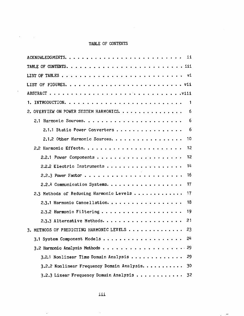
TABLE OF CONTENTS
ACKNOWLEDGMENTS.......................................................................................................... i i
TABLE OF CONTENTS............................................................................................................ i i i
LIST OF TABLES ............................................................................................................. v i
LIST OF FIGURES............................................................................................................ v i i
ABSTRACT ........................................................................................................................ v i i i
1. INTRODUCTION. ......................................................... 1
2. OVERVIEW ON POWER SYSTEM HARMONICS......................................................... 6
2.1 Harmonic S o u rce s ......................................................................................... 6
2.1.1 S t a t i c Power C o n v e r t e r s ........................................................... 6
2.1.2 O ther Harmonic S o u rce s ............................................................... 10
2.2 Harmonic E f f e c t s ......................................................................................... 12
2.2.1 Power Components ............................................................................ 12
2.2.2 E l e c t r i c I n s t r u m e n t s ................................................................... 14
2 .2 .3 Power F a c t o r ................................................................................... . 16
2 .2 .4 Communication System s................................................................... 17
2.3 Methods o f Reducing Harmonic L e v e ls ........................................... 17
2.3.1 Harmonic C a n c e l la t io n ................................................................... 18
2.3.2 Harmonic F i l t e r i n g ........................................................................ 19
2.3.3 A l t e r n a t iv e M ethods............................................................................ 21
3. METHODS OF PREDICTING HARMONIC LEVELS ................................................ 23
3.1 System Component M o d e ls ....................................................................... 24
3 .2 Harmonic A nalysis Methods ........................................................................ 29
3.2.1 N o n lin e a r Time Domain A n a l y s i s ............................................. 29
3 .2 .2 N o n lin e a r F requency Domain A n a ly s is ................................... 30
3 .2 .3 L in e a r F requency Domain A n a l y s i s ............................................. 32
i i i

4. PROBABILISTIC MODELING OF POWER SYSTEM HARMONIC&............................ 36
4.1 C l a s s i f i c a t i o n o f N o n lin e a r L o a d s ................................................. 38
4.2 P r o b a b i l i ty D is t r ib u t io n o f Harmonic I n j e c t i o n ...................... 39
4 .2 .1 Sum o f Random Number o f Constant C u rren ts ................................... 42
4 .2 .2 Sum o f Constant Number o f Random C u rren ts ................................... 42
4 .2 .3 Sum o f Random Number o f Random C u rren ts .......................44
4 .2 .4 R esultan t n -th Harmonic Current In je c t io n ................................... 45
4.3 P r o b a b i l i t y D is t r ib u t io n o f Harmonic P ro p a g a tio n .................... 46
4.4 C o m pu ta tiona l M ethods .......................................................................... 48
4.5 Example and D isc u ss io n o f R e s u l t s ................................................. 49
4 .5 .1 S t a t i s t i c a l Data o f Nonlinear Loads...............................................51
4 .5 .2 Sim ulation R esu lts and D iscussion...................................................54
4.6 P o te n t i a l A p p l ic a t io n s ............................................................................... 58
4 .6 .1 S e ttin g L im ita tions on Harmonic Levels .................................. 58
4 .6 .2 Power Factor C o rrec tio n ........................................................................59
4 .6 .3 Communication In te rfe re n c e ........................................................... 60
4 .6 .4 E stim ating Line L o s s e s ........................................................................60
4 .6 .5 Equipment Design ................................................................................ 61
5. MAXIMUM HEATING AND INSULATION STRESS ON UNTRANSPOSED TRANSMISSION LINES UNDER NONSINUSOIDAL CONDITIONS................................. 62
5.1 E x p ress io n f o r S in g le Harmonic......................................................... 63
5.2 Maximum S in g le Harmonic C u rre n t and V o l t a g e ............................ 66
5.2.1 G lo b a l C onvergence M e th o d ..................................................... 67
5.2.2 L o ca l C onvergence M ethod.......................................................... 69
5.3 Maximum O v e r a l l RMS C u rre n t and Peak V o lta g e .......................... 71
5.4 Maximum D is to r t io n F a c to r .................................................................. 78
5.5 S in g le -P h a se L in e s ........................................................................................ 78
iv

5.6 N um erical Example and D iscu ss io n o f R e s u l t s .......................... 80
6 . CONCLUSIONS.............................................................................................................. 88
REFERENCES............................................................. .....................................................90
APPENDIX I ; HARMONIC COMPUTATION OF DISTORTED WAVEFORMS ....................... 96
APPENDIX I I : EQUIVALENT SERIES IMPEDANCE AND SHUNT ADMITTANCE OFTRANSMISSION LINES..................... ......................................................98
V IT A ................................................................................................................................... 102
v

LIST OF TABLES
TABLE I . System Component Models.........................................................................25
TABLE I I . Harmonic Levels (.% o f Fundamental) and th e i r Phase Angles(Degrees w . r . t . V*) a t Receiving Line End..................... .... 82
TABLE I I I . Computed G lobal Maxima and Locations o f RMS C urrents,Peak V oltages and D is to rtio n F ac to rs .......................................... 83

LIST OF FIGURES
F ig . 1. C onverter E quivalen t C irc u it : (a) R e c tif ie r , (b) In v e r te r . . 7
F ig . 2 . Twelve-Pulse C onverter C onfiguration ............................................ 18
F ig . 3• Reduced E quivalent C irc u it o f C onverter-F ilter-Pow er Network 20
F ig . 4 . Induction Motor Model: (a) Exact, (b) Approximate.................27
F ig . 5 . S im plest E quivalen t C irc u it fo r Harmonic A nalysis .................33
F ig . 6 . Power System w ith M ultip le Nonlinear Loads ................................ 34
F ig . 7 . Load C o m position ....................................................................................41
F ig . 8 . Flowchart o f In te g ra tio n Method. . 50
F ig . 9 . Flowchart o f Monte C arlo Sim ulation Method ................................ 51
F ig . 10. Three-Bus D is tr ib u tio n System: (a) One-Line Diagram,(b) E quivalent C irc u it fo r 5 -th Harmonic ..................................... 52
Fig. 11. 5 -th Harmonic C urrent Generated by T ypical B attery Charger . 53
F ig . 12. PDFs o f (a) Real and (b) Imaginary P a rts o f 5 - th HarmonicC urrent in Time In te rv a ls 2 , 3 and 4 ............................................55
F ig . 13. PDFs o f Random Component o f 5 -th Harmonic C urrent Magnitudein Time In te rv a ls 2 , 3 and 4 ............................................................ 56
F ig . 14. Expected Value o f 5 -th Harmonic C urrent Versus Time.............57
F ig . 15. PDFs of Random Component o f 5 -th Harmonic Voltage Magnitudea t Bus 3 in Time In te rv a ls 2 , 3 and 4 ............................................57
F ig . 16. Flowchart o f G lobal Convergence Method ........................................ 69
F ig . 17. Flowchart o f Local Convergence Method..........................................72
Fig! 18. Flowchart fo r Computing Maximum Peak V o l ta g e ......................... 77
F ig . 19. Three-Phase Transm ission Line (Phase W ires: 795000 CM 26/7ACSR; S te e l Ground W ires: R = 4 ft/m i, and GMR = 0.001 f t ) . . 81
F ig . 20. V aria tio n o f RMS C u rren ts ...................................................................84
F ig . 21. V aria tio n o f Peak (a) Phase V oltages and (b) Line Voltages . 85
F ig . 22. D is to r tio n F acto r o f (a) C urren ts, (b) Phase V oltagesand (c) Line V oltages............................................................................. 86
F ig . 23. Instan taneous Phase 'a ' Voltage in Search Region ................... 87

ABSTRACT
In recen t y ears , power system harmonic l e v e l s have increased s ig
n i f i c a n t l y due to th e e v e r - in c r e a s in g u se o f n o n l in e a r lo a d s which
p r im a r i ly c o n s i s t o f power e l e c t r o n i c d e v ic e s . The e f f e c t o f th e s e
harm onics on power system com ponents r e p r e s e n ts a s e r io u s p rob lem to
u t i l i t y companies and consumers.
A su rv e y o f power system harm onics as g e n e ra te d m ain ly by s t a t i c
ac/dc power co n v erte rs i s p re se n te d . A sp ec ts co n ce rn in g harm onic i n
j e c t i o n , t h e i r e f f e c t s on system com ponents and harm onic r e d u c tio n
techniques a re inc luded . Harmonic a n a ly s is methodologies a re d iscussed
and compared in term s o f e ff ic ie n c y and accuracy.
The need o f a s to c h a s tic trea tm ent o f harmonic v o ltag es and c u rre n ts
i s c le a r ly explained . A novel p r o b a b i l i s t ic model o f analyzing power
system harmonics i s developed. Depending on th e i r opera ting modes and
sw itching s ta te s , n o n lin ea r loads connected to each d is tr ib u tio n bus are
decomposed in to four d i s t in c t ca teg o rie s o f harmonic cu rren t in je c tio n .
The p r o b a b i l i t y d i s t r i b u t i o n o f th e t o t a l random c u r r e n t in je c te d a t
each bus i s determined a f te r making some reasonab le assumptions. Proba
b i l i t y c h a r a c t e r i s t i c s o f th e r e s u l t i n g harmonic v o ltag es are c a lc u
la te d . Two com putational methods, i.e ., th e d ire c t in te g ra tio n method
and th e Monte C arlo s im u la tion method, a re presen ted fo r determ ining th e
s t a t i s t i c a l c h a r a c te r is t ic s o f th e harmonic s ig n a ls . The procedure i s
dem onstrated by an example which i l l u s t r a t e s th e p ro b a b il i ty aspects o f
power system harmonics. P o t e n t i a l a p p l ic a t io n s o f th e p r o b a b i l i s t i c
model are a ls o considered.
v i i i
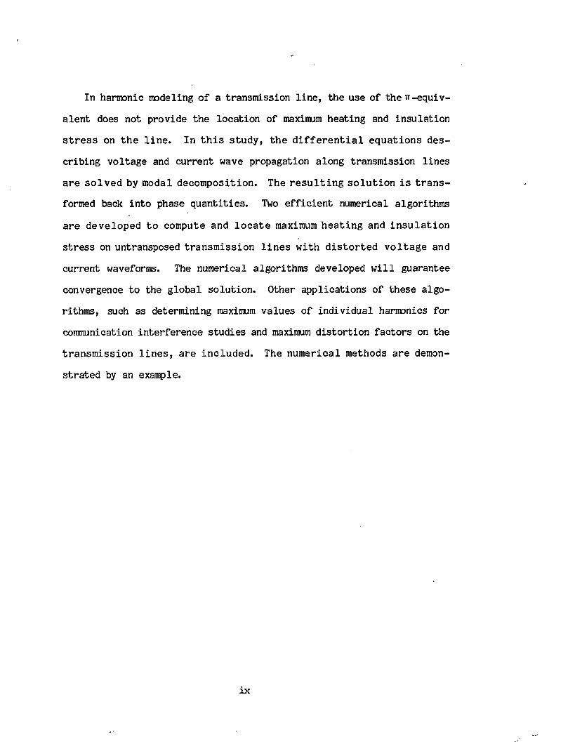
In harmonic modeling o f a transm ission l in e , th e use o f th e ir -e q u iv
a le n t does n o t p rov ide th e lo c a tio n o f maximum h ea tin g and in s u la tio n
s t r e s s on th e l i n e . In t h i s s tu d y , th e d i f f e r e n t i a l e q u a tio n s d e s
c r ib in g v o lta g e and c u rre n t wave propagation a long transm ission l in e s
a re s o lv e d by modal d eco m p o sitio n . The r e s u l t i n g s o lu t io n i s t r a n s
formed back in to phase q u a n ti t ie s . Two e f f ic ie n t num erical a lgorithm s
a re d e v e lo p e d to compute and l o c a t e maximum h e a t in g and i n s u l a t i o n
s t r e s s on untransposed tra n s m is s io n l i n e s w ith d i s to r t e d v o l ta g e and
cu rren t waveforms. The num erical a lgorithm s developed w i l l guarantee
convergence to the g lo b a l so lu tio n . Other a p p lic a tio n s o f th ese a lg o
rithm s, such as determ ining maximum v a lu es o f in d iv id u a l harmonics fo r
communication in te rfe re n c e s tu d ie s and maximum d is to r t io n fa c to rs on the
tra n s m is s io n l i n e s , a re in c lu d e d . The n u m e ric a l m ethods a re demon
s tr a te d by an example.

1. INTRODUCTION
The ex is ten ce o f v o lta g e and cu rren t d is to r t io n on power systems has
been re c o g n iz e d s in c e th e e a r ly days o f a l t e r n a t i n g c u r r e n t . In th e
p a s t, harmonic sources were lim ited to transfo rm ers caused by s a tu ra tio n
and e l e c t r i c m achines. In m ost c a s e s , harm onic m agnitudes w ere v e ry
l im i t e d and c o u ld be reduced to a c c e p ta b le l e v e l s th ro u g h th e u se o f
w ye-delta transfo rm er connections [13.
In th e l a s t two decades, however, th e number o f n o n lin ea r loads has
ra p id ly increased due to th e recen t advances in h igh power semiconductor
sw itc h in g d e v ic e s . The p r o l i f i c a t i o n o f power c o n v e r te r s w hich a re
w idely used in high v o lta g e d ire c t cu rren t (HVDC) transm ission , motor
speed c o n tro l , u n in te rru p ted power su p p lie s (UPS), b a tte ry chargers and
p h o to v o lta ic s ta t io n s suggests a renewed look a t harmonic s ig n a ls in
power systems [2 ]. Furtherm ore, in th e near fu tu re , e l e c t r i c u t i l i t i e s
a n tic ip a te i n s t a l l i n g energy s to rage dev ices and th e i r asso c ia ted ac/dc
co n v erte r equipment on d is t r ib u tio n feeders to augment c e n tr a l - s ta t io n
power su p p lie s [ 33; hence, harmonic sources w i l l continue to increase .
Today, i t i s c le a r th a t power system harmonics are becoming a very
s e r io u s p rob lem which r e p r e s e n ts f o r th e f i r s t tim e a p o t e n t i a l o f
d is tu rb in g th e normal o p era tion o f both consumer loads and power n e t
work. The e f f e c t o f harm onics on power a p p a ra tu s [4 ] - [5 3 , in s tru m e n ts
[63—[73 and communication systems [83 —[93 rep re se n ts se r io u s problems to
u t i l i t y companies. Therefore, harmonic co n sid era tio n fo r any in d u s t r ia l
power system comnands as much a tte n tio n as sh o rt c i r c u i t and o v e rv o ltag e
consid era tio n s [23.
Harmonic p rob lem s can be in v e s t i g a t e d by a c t u a l l y m easuring th e
1
2
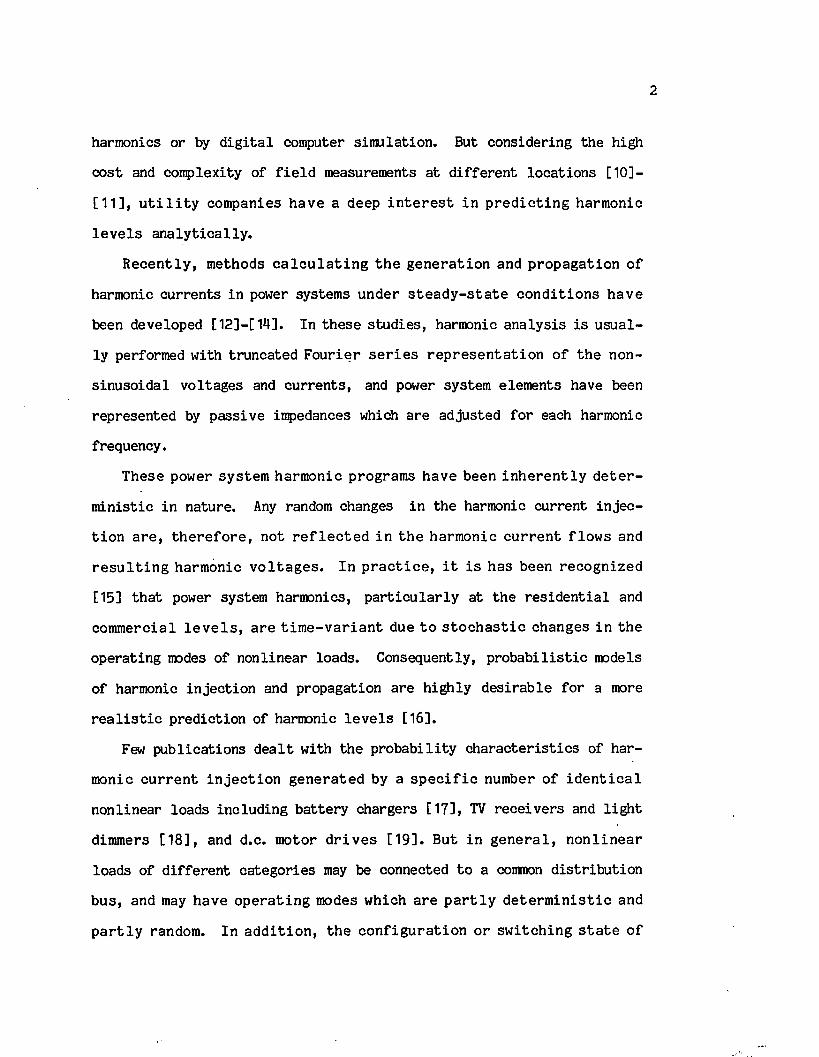
harmonics or by d ig i t a l computer s im u la tio n . But considering the high
c o s t and com plexity o f f i e l d measurements a t d if f e r e n t lo c a tio n s [ 10] -
[ 1 1 ] , u t i l i t y com panies h av e a deep i n t e r e s t in p r e d ic t in g harm onic
l e v e l s a n a ly t ic a l ly .
R e c e n tly , m ethods c a l c u l a t i n g th e g e n e ra t io n and p ro p a g a tio n o f
harmonic c u rre n ts in power system s u n d er s t e a d y - s t a t e c o n d it io n s h av e
been developed [12 ]-[14 ]. In th e se s tu d ie s , harmonic a n a ly s is i s u su a l
ly performed w ith tru n ca ted F o u r ie r s e r i e s r e p r e s e n ta t io n o f th e non-
s in u so id a l v o ltag es and c u rre n ts , and power system elem ents have been
rep resen ted by p a ss iv e impedances which a re ad justed fo r each harmonic
frequency.
These power system harm onic program s have been in h e r e n t ly d e t e r
m in is tic in na tu re . Any random changes in th e harmonic cu rren t in je c
t io n a r e , th e r e f o r e , n o t r e f l e c t e d in th e harm onic c u r r e n t f lo w s and
r e s u l t i n g harm onic v o l ta g e s . In p r a c t i c e , i t i s h as been re c o g n ize d
[15] th a t power system harmonics, p a r t i c u la r ly a t th e r e s id e n t ia l and
com m ercial l e v e l s , a re t im e - v a r i a n t due t o s to c h a s t i c changes in th e
o p era tin g modes o f n o n lin ea r loads. Consequently, p ro b a b i l i s t ic models
o f harmonic in je c tio n and propagation a re h ig h ly d e s ira b le fo r a more
r e a l i s t i c p re d ic tio n o f harmonic l e v e l s [16].
Few p u b lic a tio n s d e a l t w ith th e p ro b a b il i ty c h a ra c te r is t ic s of h a r
monic c u r r e n t in j e c t io n g e n e ra te d by a s p e c i f i c number o f i d e n t i c a l
n o n lin ea r loads in c lu d in g b a tte ry chargers [17], TV re c e iv e rs and l ig h t
dimmers [1 8 ] , and d .c. m otor d r iv e s [1 9 ] . But in g e n e r a l , n o n l in e a r
loads o f d if f e r e n t ca teg o rie s may be connected to a common d is tr ib u tio n
b u s , and may have o p e ra t in g modes w hich a re p a r t l y d e te r m in is t i c and
p a r t l y random. In a d d i t io n , th e c o n f ig u ra t io n o r s w itc h in g s t a t e o f

3
n o n lin ea r loads may be fix ed , vary ing d e te rm in is t ic a l ly or randomly w ith
tim e.
The harmonic l e v e l s in high v o ltag e power system s, e s p e c ia l ly those
g e n e ra te d by HVDC s t a t i o n s , a r e found to be p r a c t i c a l l y c o n s ta n t in
n a tu re [11]. Consequently, harmonic cu rren ts and v o ltag es can be p re
d ic ted by conven tional power system harm onic program s [1 2 ] - [1 4 ] where
transm ission l in e s are rep resen ted by th e i r ir-eq u iv a len t c i r c u i t . Since
th e lo n g l i n e i r - e q u iv a le n t c i r c u i t i s a tw o -p o r t netw ork , o n ly th e
te rm in a l v o lta g e s and c u rre n ts o f th e transm ission l in e can be ca lcu
la te d . As a r e s u l t , p o s s ib le maximum va lu es o f the o v e r a l l rms cu rren t
and peak v o lta g e a long th e l in e due to stand ing wave phenomena a re not
r e a d i l y known. These maxima c o u ld be l a r g e r th a n th e co rre sp o n d in g
v a lu es a t th e l in e te rm in a ls and i f ignored, in s u la tio n damage, over
h ea tin g o r communication in te rfe re n c e could tak e p lace .
S h u ltz e t a l . [20] p resen ted a method to compute th e maximum v a lu e
o f a s in g le harmonic c u rren t or v o ltag e on an e q u iv a le n t s in g le -p h ase
transm ission l in e . However, i t i s recognized th a t th e maximum o v e r a l l
rms c u rren t and t o t a l peak v o lta g e a re o f g re a te r importance. F u rth er
more, transm ission l in e s a re g e n e ra lly m ultiphase and o fte n untransposed
[ 2 1 ], thus cannot be rep resen ted by an e q u iv a le n t s in g le -p h ase lin e .
The o b je c tiv e o f th i s study i s (1) to develop a p r o b a b i l i s t ic method
o f m odeling power system harmonics, and (2) to develop e f f ic ie n t numeri
c a l m ethods f o r lo c a t in g and com puting th e maximum l i n e h e a t in g and
in s u la t io n s t r e s s on unbalanced transm ission l in e s under nonsinusoidal
cond itions. Before th e se s p e c if ic problems are considered, an overview
on power system harmonics and d iscussion o f th e e x is t in g harmonic study

m ethodologies are given. The m a te ria l i s arranged in fou r chap ters.
C hap ter 2 g iv e s an o v e rv ie w o f power system harm onics in c lu d in g
harmonic sources, t h e i r e f f e c ts on power system components and e x is t in g
methods o f harmonic compensation. The major source o f harmonics i s the
s t a t i c power co n v erte r. O ther sources o f harmonics inc lude transform er
sa tu ra tio n , e l e c t r i c machines, a rc furnaces and w elders, gaseous d is
charge l ig h tin g and s t a t i c VAR compensators. Power system harmonics are
known t o a f f e c t m ost power system a p p a ra tu s , power in s tru m e n ts and
communication systems. The most popu lar harmonic m itig a tio n techniques
c o n s is t o f harmonic c a n c e lla t io n and harmonic f i l t e r i n g methods. A lte r
n a tiv e methods o f harmonic compensation, such as cu rren t in je c tio n and
m ag n etic f l u x com pensa tion , h ave n o t been d e v e lo p e d f o r h ig h power
r a t in g s .
C h ap ter 3 d is c u s s e s power system component m odels and methods o f
harmonic a n a ly s is ; namely, th e p iece-w ise l in e a r time-domain a n a ly s is ,
th e n o n l in e a r frequency -dom ain a n a ly s i s and th e l i n e a r f re q u e n c y -
domain a n a ly s is . The methods are compared in terms o f th e i r accuracy and
c o m p le x ity . The m ost e f f i c i e n t and w id e ly used method i s th e l i n e a r
frequency -dom ain s im u la t io n m ethod, b u t th e most a c c u ra te t o o l y e t
developed i s th e n o n lin ea r frequency-domain method.
C hap ter ^ in tr o d u c e s a p r o b a b i l i s t i c m odeling o f power system
harm onics and p ro v id e s two n u m e ric a l a lg o r i th m s f o r com puting th e
p ro b a b il i ty c h a r a c te r is t ic s o f harm onic c u r r e n ts and v o l ta g e s . A f te r
c la s s i fy in g n o n lin ea r loads in to fo u r d if f e r e n t c a teg o rie s in term s o f
t h e i r o p e ra t in g modes, p r o b a b i l i t y d i s t r i b u t i o n s o f harm onic c u r r e n t
i n j e c t i o n and p ro p a g a tio n a re d e r iv e d . The p r o b a b i l i s t i c method o f
harmonic a n a ly s is i s dem onstrated by an example, and p o te n t ia l a p p lic a

5
tio n s o f th i s method a re d iscussed.
F i n a l l y , th e p ro b lem o f l o c a t in g and com puting maximum h e a t in g
(maximum t o t a l rms cu rren t) and in s u la t io n s t r e s s (maximum o v e r a l l peak
v o lta g e ) on unbalanced transm ission l in e s under nonsinuso idal cond itions
i s in v e s tig a te d in chap ter 5. Two num erical methods fo r computing th e
maximum rms cu rren t and an a lgo rithm to fin d th e maximum peak v o ltag e ,
both o f which guarantee convergence to the g lo b a l s o lu tio n , a re d e v e l
oped. O th er a p p l i c a t io n s o f th e a lg o r i th m s , such as com puting th e
maximum o f each c u r r e n t harm onic f o r f in d in g th e te le p h o n e in f lu e n c e
f a c to r and maximum d i s t o r t i o n f a c to r s fo r conform ing w ith harm onic
l im its , a re inc luded . The s p e c ia l cases o f s in g le -p h ase and balanced
th re e -p h a s e t r a n s m is s io n l i n e s a re considered. The num erical methods
a re i l l u s t r a t e d by an example.

2 . OVERVIEW ON POWER SYSTEM HARMONICS
A b r i e f re v ie w on so u rc e s o f power system s harm o n ics, harm onic
e f f e c t s on power equipm ent and in s tru m e n ta tio n and v ario u s methods of
harmonic compensation i s g iven in th i s chap ter. Most o f the m a te r ia l i s
taken from Ref. [22] which p rov ides a concise survey o f harmonic gener
a t io n , a n a ly s i s , i n t e r f e r e n c e and r e d u c tio n . A more r ig o ro u s and
exhaustive trea tm en t o f th e se su b jec ts can be found in s e v e ra l p u b lic a
tio n s , p a r t i c u la r ly those by Kimbark [23], A r r i l la g a e t a l . [4] and the
IEEE t u t o r i a l course on power system harmonics [5 ]. Reference [24] a ls o
g iv e s a f a i r l y co m p le te b ib l io g ra p h y o f s tu d ie s on power system
harm onics.
2.1 Harmonic Sources
Power system v o lta g e and c u rren t harmonics r e s u l t from th e n o n lin ea r
o p era ting c h a ra c te r is t ic s o f c e r t a i n power sytem com ponents. E x is t in g
a n a ly t ic a l [25] and num erical [26] methods fo r computing th e harmonic
l e v e l s o f n o n s in u s o id a l w aveform s a re summarized in Appendix I . The
most common power apparatus known to generate harmonics are d iscussed in
th i s sec tio n . Emphasis i s g iven to s t a t i c power co n v erte rs s in ce they
a re w id e ly used f o r a w ide range o f power r a t in g s and r e p r e s e n t th e
major source o f harmonics.
2.1.1 S ta t ic Power C onverters
I t has been re c o g n iz e d t h a t p h a s e - c o n t r o l le d r e c t i f i e r s and i n
v e r t e r s r e p r e s e n t th e main harm onic so u rc e in power and d i s t r i b u t i o n
system s [2 ] . These c o n v e r te r s a re c o n v e n ie n t ly grouped in te rm s o f
t h e i r power r a t in g s : h ig h , medium and low power c o n v e r te r s . Each o f
6

th e se groups w i l l be b r ie f ly discussed.
L a rg e power r e c t i f i e r s , such as th o s e u sed in h ig h v o l ta g e d.c.
transm ission (HVDC), g e n e ra lly have a la rg e inductance on th e d.c. side.
The d i r e c t c u r r e n t i s th u s re a so n a b ly c o n s ta n t and th e r e c t i f i e r a c t s
l i k e a harm onic c u r r e n t so u rc e on th e a .c . s id e a s shown by th e e q u iv
a l e n t c i r c u i t in F ig . 1 (a ). For th e i d e a l c a se o f in s ta n ta n e o u s com
m utation between th e conducting elem ents, a p -p u lse co n v erte r generates
c h a r a c te r is t ic cu rre n t harmonics o f the o rder
n = pk± 1 , k = 1 ,2 ,3 . . . (1)
w ith th e i r rms v a lu e given by [23]
I = 1 -,/n = /6 1 ,/mr n X a
where I 1 i s th e fu n d am en ta l c u r r e n t (w ith no o v e r la p ) and Id i s th e
co n v erte r d ire c t cu rren t.
l ^ 7\ >
(a) (b)
Fig. 1. C onverter E q u iv a len t C irc u it: (a) R e c tif ie r , (b) In v e rte r .

I f a Y-Y connected transfo rm er i s used a t th e te rm in a ls o f a 6-p u ls e
r e c t i f i e r , then th e frequency domain re p re se n ta tio n o f l in e c u rren t i s
o y r i i i ii (t) = - ^ - I d{cos (tot) -geos (5cot) -h jc o s (7o)t) - j j c o s (Hoot) + j^cos (13oot). . . } . (2)
On th e o th e r hand, when e i th e r th e prim ary o r secondary windings o f the
r e c t i f i e r t r a n s fo rm e r a r e co n n ec ted in d e l t a , th e l i n e c u r r e n t in (2 )
becomes
o / T 1 1 1 1i (t) = I d(cos (oot) +^cos (5cot) -^cos (7oot) +jjc o s (lloot) - j^ c o s (13oot) , . . } . (3)
I f th e com m utation p e r io d i s ta k e n i n to a cco u n t, th e m agnitude o f
th e n -th cu rren t harmonic i s given by [23]
1 = 1 , F(a,g)/2D n = /3 V F(a,B)/2iroonL (4)n X
whereD = cos(a) - cos(a+3)
F (a ,3 ) = 2 [(S 1 ) 2 + (S2) z - 2S1S2cos (a+3) ] ^w ith
sin{(n+1 ) 3/ 2 }S = --------------------
(n+1 )and
s in { (n -1 ) 3/ 2 }
(n-1)
H erein, 00L i s th e e q u iv a le n t s h o r t - c i r c u i t reactance, a i s th e f i r in g
an g le and 3 i s the commutation ang le.
In a d d i t io n to th e c h a r a c t e r i s t i c c u r r e n t harm o n ics, harm onics o f
u n c h a ra c te r is t ic o rders a re a ls o produced. These harmonics a re caused
by u n b a lan ced v o l ta g e s and l i n e im pedances o r by u n eq u a l t h y r i s t o r
f i r in g an g les . The u n c h a ra c te r is t ic harmonics a re norm ally much sm a lle r

th a n th e c o rre sp o n d in g a d ja c e n t c h a r a c t e r i s t i c harmonics. I t i s sug
g e s te d t h a t u n c h a r a c t e r i s t i c harm onics o f o rd e r ( 6n - 1) and ( 6n+ 1),
n = 1 ,3 ,... fo r a 1 2 -p u ls e c o n v e r te r be ap p ro x im ated t o 15? o f th e l e v e l
computed f o r a 6 - p u ls e c o n v e r te r [ 2 7 ] , w hereas n o n c h a r a c te r i s t i c odd
m u l t ip l e s o f th e t h i r d harm onic , i . e . , 3n, n=1 , 3 , . . . , be s e t t o 1% o f
th e fundamental [283.
L a rg e pow er i n v e r t e r s , found a t th e r e c e iv in g end o f an HVDC
transm ission l in e , a re rep resen ted by c h a r a c te r is t ic harmonic v o lta g e
so u rc e s b eh ind a s e r i e s im pedance. The v o l ta g e m agnitude f o r each
c h a r a c te r is t ic frequency depends on the c o n tro l technique used to regu
l a t e th e fundamental v o lta g e . The v a lu es o f th e v o lta g e harmonic magni
tudes, th e i r phase an g les and s e r ie s impedances can be ob tained from the
m a n u fa c tu re r . I t i s n o ted t h a t f o r a n a ly s i s p u rp o se s , th e harm onic
v o l ta g e so u rc e can be c o n v e r te d i n to an e q u iv a l e n t harm onic c u r r e n t
so u rc e by N o rto n 's theorem a s shown in F ig . 1(b).
Medium power c o n v e r te r s are ga in ing wide a p p lic a tio n in motor speed
c o n tro l due to recen t advances in power sw itch ing dev ices. D irec t cur
r e n t d r iv e s , w hich s t i l l h o ld a b ig s h a re o f m otor d r iv e s , g e n e ra te
harmonic c u rre n ts which depend on th e r e l a t i v e l y sm all inductance on th e
d .c. s id e o f th e c o n v e r te r [293. On th e o th e r hand, th e c u r r e n t h a r
m onics g e n e ra te d by a .c . d r iv e s depend on th e m otor speed and th e ty p e
o f c o n tro l arrangement used. The most common types o f c o n tro l fo r such
d riv e s in c lu d e a.c. v o lta g e c o n tro l, v a r ia b le -v o lta g e v a riab le -freq u en cy
c o n tro l, v a r ia b le -c u r re n t v a riab le -freq u en cy c o n tro l, and p u lse-w id th -
m o d u la tio n c o n t r o l . The harm onic c u r r e n ts in j e c te d by each o f th e s e
d riv e s a re w e ll documented in Ref. [30].

Low Power C o n v e r te r s a re u sed in s e v e r a l home a p p l ia n c e s (TV and
s te re o re c e iv e rs , microwaves, desk computers) and o f f ic e systems (com
p u te r s ) . O th e r d e v ic e s em ploying power e l e c t r o n i c sw itc h e s in c lu d e
l ig h t dimmers, h ea tin g c o n tro l u n its and b a tte ry chargers. Because of
t h e i r low power ra tin g s , th e se co n v erte rs in je c t r e l a t i v e l y sm all h a r
monic c u r r e n ts i n to th e u t i l i t y su p p ly , b u t i f th e u se o f e l e c t r i c
v e h ic le s becomes w idely accepted, b a tte ry chargers w i l l become a major
source o f harmonics [31].
2.1.2 Other Harmonic Sources
Before th e development o f s t a t i c power co n v erte rs , harmonic d is to r
t io n was p rim arily asso c ia ted w ith e l e c t r i c machines and transfo rm ers.
O th er known so u rc e s o f harm onics in c lu d e a rc fu rn a c e s and w e ld e rs ,
f lu o re sc e n t lamps and s t a t i c VAR compensators. Each o f th ese n o n lin ea r
apparatus i s d iscussed below.
T ran sfo rm er s a tu r a t i o n , i . e . , th e d e v ia t io n from th e l i n e a r r e
la tio n s h ip between the magnetic f lu x in iro n and the m agnetizing fo rce ,
c a u se s a n o n s in u s o id a l e x c i t a t i o n c u r r e n t t o co rre sp o n d w ith a s i
n u so idal app lied v o ltag e . The e x c i ta t io n c u r r e n t d i s t o r t i o n c o n ta in s
m ainly the th i r d harmonic, but th e f i f t h and th e seventh o rder harmonics
may a ls o be la rg e enough to produce v i s ib le d is to r t io n .
T ran sfo rm ers a re a l s o known to g e n e ra te o th e r harm onic c u r r e n ts
(in rush cu rren ts ) when re -en erg ized a f t e r b e in g s w i tc h e d -o f f . B ecause
o f th e r e s id u a l f l u x in th e c o re , tra n s fo rm e rs w i l l be d r iv e n in to
extreme sa tu ra tio n during th e f i r s t seconds o f opera tion . This e f fe c t
g iv es r i s e to m agnetizing c u rre n ts o f up to 10 tim es th e ra te d cu rren t

11
E l e c t r i c m achines g e n e ra te harm onics as a r e s u l t o f th e harm onic
c o n te n ts o f th e m.m.f. d i s t r i b u t i o n . At a r o t o r s l i p s , an n - th o rd e r
harm onic in th e r o to r m.m.f. in d u ces an e.m .f. in th e s t a t o r a t a
f req u e n cy e q u a l to (n -s (n ± 1)) tim e s th e fu n d am en ta l freq u en cy [ 3 2 ] .
Nonsymmetrical ro to r windings are a ls o known to cause harmonic d is to r
t io n . In such a case, both p o s i t iv e and n eg a tiv e sequence c u rre n ts w i l l
flow in th e ro to r , c re a tin g forward as w e ll as backward ro ta t in g f ie ld s .
The harmonic frequencies o f s ta to r e.m.f. induced by th ese f i e ld s a re
(1 - 2 s ) tim e s th e fu n d am en ta l freq u en cy . V a r ia t io n s o f th e m agnetic
re lu c tan c e o f e l e c t r i c a l machines caused by s ta to r and ro to r s l o t s a ls o
generate harmonics, but th e se harmonics are not s ig n if ic a n t .
A rc fu rn a c e s and a r c w e ld e r s induce harmonics due to the n o n lin ea r
v o lta g e -c u rre n t c h a r a c te r is t ic o f power a rc s . These loads are u s u a lly
modeled as harmonic cu rre n t sources w ith th e th ird , f i f t h , seventh and
n in th o rder harmonics as th e most p re v a le n t components. The magnitudes
o f th e s e harm onics v a ry c o n t in u a l ly due t o th e random n a tu re o f a rc
c u rre n ts , e s p e c ia l ly during th e m eltin g phase.
G aseous d is c h a rg e l i g h t i n g , such as f lu o r e s c e n t , m ercury a rc and
h ig h p re s s u re sodium lam ps, i s a s i g n i f i c a n t so u rc e o f power system
harmonics, p a r t i c u la r ly in m etro p o litan a reas . The e l e c t r i c a l charac
t e r i s t i c s o f th ese lamps are q u ite n o n lin ea r, th u s g iv in g r i s e to con
s id e ra b le l e v e l s o f harmonic cu rre n ts . The magnitudes o f th e th i r d and
f i f t h harm onic c u r r e n ts g e n e ra te d by t y p i c a l f lu o r e s c e n t lam ps a re
re s p e c tiv e ly on the order o f 21% and 7% o f th e fundamental component.
S t a t i c VAR co m p en sa to rs , b ecau se o f t h e i r f a s t re sp o n se , h ig h e f
f ic ie n c y and low maintenance, a re f in d in g in c reas in g use in improving
power system v o lta g e re g u la tio n and power fa c to r c o rrec tio n [33]. These

12
co m p en sa to rs u se t h y r i s t o r - c o n t r o l l e d r e a c to r s o r c a p a c i to r s , th u s
g en era tin g co n sid e rab le amounts o f harmonic d is to r t io n . The magnitudes
o f th e se harmonics depend on the de lay an g les o f th e SCRs. The dominant
harm onic c u r r e n ts a re o f th e t h i r d and f i f t h o rd e rs which can r e
s p e c tiv e ly reach 30% and 10% o f th e fundamental component.
2.2 Harmonic E ffec ts
Harm onics may a f f e c t any o f th e fo u r c a te g o r ie s : power components
(cap ac ito rs banks, transfo rm ers, e l e c t r i c machines, transm ission l in e s ) ,
in s tru m e n ta t io n ( r i p p l e c o n t r o l system s, p ro te c tiv e dev ices, watthour
m e te rs ) , power e f f i c i e n c y and com m unication sy stem s. Each o f th e s e
c a te g o rie s w i l l be d iscussed below.
2.2.1 Power Components
Shunt C a p a c ito rs . C a p a c ito r im pedance d e c re a se s w ith freq u en cy .
F o r t h i s re a so n , c a p a c i to r banks a c t as " s in k s" f o r harm onic c u r r e n ts .
In a system w ith d is tr ib u te d harmonic sources, th e harmonics w i l l con
v e rg e t o th e c a p a c i to r banks, and may r e s u l t in fu se -b lo w in g or
c a p a c i to r f a i l u r e . The t o t a l power lo s s in c a p a c i to r banks in th e
presence o f harmonics i s expressed by
Pl o s s = * C (tan6)mnv£ (5)n-1
where ( ta n 6 ) i s th e l o s s f a c t o r , u>n and Vn a r e th e a n g u la r freq u en cy
and th e rms v a lu e o f th e n -th harmonic v o ltag e .
C apacitor banks, such as th ose used fo r power fa c to r co rrec tio n , can
a ls o form a resonan t c i r c u i t w ith th e r e s t o f th e system impedance a t a
frequency near a harmonic frequency. This can r e s u l t in o v e rv o lta g es

and e x c e s s iv e c u r r e n ts o f te n le a d in g to t h e i r d es tru c tio n . Moreover,
th e t o t a l r e a c tiv e power in c lu d in g th e fundamental and harmonics should
not exceed th e ra te d r e a c t iv e power.
T ran sm iss io n L in es . The flow o f harmonic c u rre n ts in transm ission
l in e s causes a d d itio n a l power lo s s as given by
Pl o s s = " < «n=2
w here Rn i s th e l i n e r e s i s t a n c e a t th e n - th harm onic freq u en cy , i t i s
noted th a t Rn in c reases w ith frequency due to sk in e f fe c t .
The p re se n c e o f harm onic v o l ta g e s cau se s a r i s e in th e l i n e in s u
l a t i o n s t r e s s , p a r t i c u l a r l y in c a b le t r a n s m is s io n . S in ce th e peak
v o lta g e depends on th e phase re la tio n s h ip between th e harmonics and th e
fundam ental, i t i s p o s s ib le fo r th e peak v o lta g e to be h igher than th e
ra te d v a lu e w h ile the rms v o lta g e i s w e ll w ith in l im its . The e f fe c t o f
h igh peak v o ltag es sh o rtens th e l i f e expectancy o f transm ission l in e s
and cab les .
T ran sfo rm ers . V oltage harmonics can cause transfo rm ers to be under
h igher in s u la t io n s t r e s s . This, however, i s no t a problem s in ce t r a n s
fo rm ers a re i n s u l a t e d f o r much h ig h e r v o l ta g e l e v e l s . On th e o th e r
hand, harmonic c u rre n ts cause a d d itio n a l copper lo s se s which r e s u l t in
in c re a s e d h e a tin g . T hese lo s s e s a re i n s i g n i f i c a n t f o r th e harm onic
l e v e l s e x p ec ted in d i s t r i b u t i o n system s C < 10%) [33 . However, th e s e
lo s se s must be taken in to account in co n v erte r transfo rm ers where th e
harmonic l e v e l s a re much h igher than 10%.
E l e c t r i c a l M achines. A d d it io n a l power lo s s i s th e m ost s e r io u s
e f f e c t o f harm onics on a .c . m achines. The c a p a b i l i t y o f a m achine to
cope w ith ex tra lo s se s w i l l depend on th e o v e r a l l machine tem perature

14
r i s e and l o c a l o v e rh e a t in g . A ccording to R ef. [3^1 , su p p lem en ta ry
h ea tin g a lone can l im it th e v o lta g e harmonic d is to r t io n fo r induction
motors to 10%.
I t i s noted th a t in th e presence o f harmonics, th e damper winding in
synchronous m achines c a r r i e s c u r r e n t c o n tin u o u s ly . T h e re fo re , th e s e
damper w ind ing lo s s e s h av e t o be ta k e n in to acco u n t in th e d e sig n
p ro c e s s , p a r t i c u l a r l y i f th e g e n e ra to r i s fe e d in g la r g e s t a t i c con
v e r t e r s . The e f f e c t o f v o l ta g e harm onics on th e mean to rq u e i s n o t
s i g n i f i c a n t f o r harm onic l e v e l s up to 20% [3 5 ] . However, p u l s a t in g
to rq u e s caused by th e i n t e r a c t i o n betw een fu n d am en ta l and harm onic
f lu x e s can p o s s ib ly r e s u l t in m ech an ica l o s c i l l a t i o n s . T h e re fo re ,
a n tic ip a te d mechanical v ib ra tio n s should be avoided.
2.2.2 E le c tr ic In s tru m e n ts
W atthour M ete rs . In d u c tio n w a tth o u r m e te rs , which a re i n i t i a l l y
c a l i b r a t e d f o r p u re s in u s o id a l v o l ta g e s and c u r r e n ts , may lo s e t h e i r
accu racy w ith d i s t o r t e d w aveform s. Based on th e r e s u l t s o f r e c e n t
s tu d ie s [ 6 ], [ 36 ], th e fo llo w in g conclusions a re made:
(a) The freq u en cy re sp o n se c u rv e o f in d u c tio n w a tth o u r m e te rs shows
r e l a t i v e l y la rg e r e g is t r a t io n e r ro rs fo r in d iv id u a l power harmonics a t
h ig h e r frequencies.
(b) Because o f th e meter n o n lin e a r ity , th e sim ultaneous r e g is t r a t io n of
m u ltip le power harmonics i s s l i g h t l y d if f e r e n t from th e sum o f r e g i s t r a
t io n s th e power harmonic components would produce in d iv id u a lly .
(c) For f a i r b i l l i n g co n sid era tio n s , not on ly the magnitude but a ls o th e
d ire c tio n o f power harmonic flow i s o f importance s in ce th e e rro r sign
i s m ainly determined by th e i r r e l a t i v e d ire c tio n s .

15
(d) With a s in u so id a l v o lta g e waveform, th e r e g is t r a t io n e rro r i s caused
by th e n o n lin e a r ity o f th e magnetic c i r c u i t s , and i s r e l a t i v e ly sm all
u n le s s th e t h i r d harm onic c u r r e n t component i s la r g e . In c a se s where
b o th th e v o l ta g e and c u r r e n t a re d i s t o r t e d , th e e r r o r i s r e l a t i v e l y
la rg e even fo r sm all v o lta g e d is to r t io n fa c to rs .
R ip p le C on tro l and C a r r ie r C urrent Systems. R ipple c o n tro l systems,
such as th e one used fo r remote c o n tro l o f s t r e e t l ig h tin g , opera te in a
freq u en cy ran g e o f 290-1650 Hz. Thus, th e p re se n c e o f harm onics in
power l in e s may cause s ig n a l b lock ing o r m aloperation o f r ip p le r e la y s
[23]. The am plitude a t which a v o lta g e harmonic w i l l a f fe c t the r ip p le
r e la y i s a func tion o f th e re la y d e tec tio n c i r c u i t .
C a rrie r c u rre n t systems op era te in the range o f 5-10 kHz. I t would
appear th a t p o te n t ia l ly in te r fe r in g harmonics from n o n lin e a r loads w i l l
be o f a m agnitude to o low to cau se p rob lem s in c a r r i e r system s. How
e v e r , c o n v e r te r s can be tro u b le so m e becau se o f t h e i r v o l ta g e n o tch es
c re a tin g h igh frequency harmonics.
P r o t e c t iv e R e lay s . Harmonics can degrade th e o p era ting c h a rac te r
i s t i c s o f p r o t e c t i v e r e l a y s depending upon th e d e s ig n f e a tu r e s and
opera tion p r in c ip le . T ests show th a t both e lec trom echan ica l and s t a t i c
r e l a y p e rfo rm an ces a re a f f e c te d by waveform d i s t o r t i o n [7 ] , C373. In
p a r t ic u la r , th e c h a r a c te r is t ic s o f overcu rren t and o v e rv o lta g e re la y s
change d r a m a t ic a l ly in th e p re se n c e o f harm o n ics, and th e o p e ra t in g
to rq u e s o f some e le c tro m e c h a n ic a l r e l a y s can be re v e r s e d a t c e r t a in
harmonic frequencies. D ig ita l r e la y perfo rm ance r e ly in g on ze ro c ro s
sin g s o f s ig n a ls can obv iously be degraded by excessive harmonic content
in th e system.

16
2.2.3 Power Factor
Power fa c to r re p re se n ts a fig u re o f m erit o f th e ch a rac te r o f power
consumption. I f the v o lta g e and cu rren t a re expressed by
00
and
v ( t) = I V sin(ncot + a ) (7 )n = l
i ( t ) = J i ^ I sin(nu>t + a + <J> ) , r a \. n n n w /n = l
th e n th e power f a c to r i s g iv e n by th e r a t i o o f a v e ra g e power P to
a p p a re n t power S, i . e . ,
ip 00
v (t) i ( t ) d t £ V I cos (4 )™ , n n n, P 0 n = l . . .p f = _ = = ( 9)
V I t( Z v 2) ( £ I 2)]*5rms rms , n , nn = l n = l
Since the re a c t iv e power i s defined by [38]
Q= £ V I sin(* ) , (10)n n nn = l
then th e apparent power S can be expressed by
S = (P2 + Q2 + D2)*5 (11)
where D i s an a d d itio n a l component designated as d is to r t io n power.
Under s in u s o id a l c o n d i t io n s , u n i ty power f a c to r can e a s i l y be
achieved by p la c in g a p a ss iv e elem ent (capac ito r o r re a c to r) in p a r a l l e l
w ith th e lo a d . However, power f a c to r com pensation i s n o t s t r a i g h t
fo rw ard when v o l ta g e and c u r r e n t w aveform s a re d i s to r t e d . A p a s s iv e
network can inprove th e power fa c to r by compensating th e re a c t iv e power
in ( 10), b u t u n i ty power f a c to r canno t be o b ta in e d because o f th e d i s
to r t io n power defined in (11).

17
2.2. 3 Communication Systems
Most d is t r ib u t io n system harmonic frequencies l i e in th e range used
in commercial vo ice transm ission (200 - 3500 Hz). Because of the g rea t3 5d iffe ren c e between th e power l e v e l s o f a d is t r ib u t io n c i r c u i t (10 -10 W)
and a te le p h o n e c i r c u i t ( 10- 5- 10- 3W), th e p re se n c e o f harm onics may
r e s u l t in p e rc e p tib le or even unaccep tab le te lephone noise. Harmonic
in te rfe re n c e w ith communication systems i s due to proxim ity and exposure
o f th e com m unication c i r c u i t s to th e power netw ork . C o u p lin g betw een
te le p h o n e and power c i r c u i t s i s th ro u g h co n d u c tio n , lo o p in d u c tio n ,
lo n g itu d in a l e l e c t r o s t a t i c o r e lec trom agnetic induc tion , w ith e le c t r o
magnetic coup ling as the dominant fa c to r .
Telephone in te rfe re n c e i s o ften measured by th e I.T product where I
i s th e t o t a l rms c u r r e n t and T i s th e T (e lephone) I ( n f lu e n c e ) F (a c to r )
defined by [23 ]
00 2*T IF = [ Z (5 n f C V 2 ) ] / V ( 1 2 )n n ' rms ' '
n = l
where Cn i s th e C-message w eighting a t the n - th harmonic frequency and f
i s th e r a te d l i n e a r freq u en cy . T ran sm iss io n te c h n iq u e s such as u n d e r
ground cab le s and microwave lin k s have minimized exposure o f communica
t io n c i r c u i t s to power harmonics. However, th e re a re s t i l l cases where
th e p o le l in e i s shared by both power and te lephone l in e s .
2.3 Methods o f Reducing Harmonic L evels
In o rd er to keep power system harmonics a t accep tab le l e v e l s , h a r
monic c o n tro l may be req u ired a t p a r t i c u la r harmonic sources, or on th e
power netw ork in g e n e r a l . The p r i n c i p a l r e d u c tio n m ethods f o r la r g e
co n v erte rs a re harmonic c a n c e lla t io n and harmonic f i l t e r i n g . S ev e ra l

o th e r harmonic co n tro l methods a re a v a i la b le bu t have no t been adopted
fo r la rg e co n v erte rs .
2.3.1 Harmonic C an c e lla tio n
Using t h i s method, harmonic c o n tro l tak es p la ce a t th e source i t s e l f
th ro u g h th e c a n c e l l a t i o n o f c e r t a i n harm onics by in c r e a s in g th e con
v e r t e r p u ls e number p in th e c h a r a c t e r i s t i c harm onic o rd e r e q u a tio n
given in (1). Harmonic c a n c e lla t io n in v o lv e s th e use o f e i th e r t r a n s
fo rm ers ( fo r r e c t i f i e r s ) o r s p e c i a l i z e d m ag n etics ( fo r i n v e r t e r s ) to
p h a se -sh if t m u ltip le co n v e rte r u n its in o rder to o b ta in c a n c e lla t io n of
some harmonics which are in h e re n tly p resen t in th e in d iv id u a l co n v e rte r
u n i ts .
As an example, Fig. 2 shows a tw e lv e -p u lse co n fig u ra tio n c o n s is tin g
o f two s ix -p u ls e p h a se -c o n tro lle d r e c t i f i e r s . The r e s u l ta n t a.c. cu r
r e n t i s g iv e n by th e sum o f th e c u r r e n ts f lo w in g in th e Y-Y and Y-A
tra n sfo rm e rs :
i ( t ) = Id{cos(wt)-^cos(13(jJt)+j^cos(23tot)-~cos(23<jot). • .}• (13)
6 -P u lse Conv.AC Bus
Y-YC onverter T ran sf.
6 -P u lse Conv.
Y-A
F ig . 2 . Twelve-Pulse Converter C onfiguration .

The r e s u l t in g c u rren t con ta in s only harmonics o f th e o rder 12i±1. I t i s
n o te d t h a t th e harm onic c u r r e n ts o f th e o rd e r 6 k ±1 (w ith k odd)
c i r c u la t e between th e two co n v erte r transfo rm ers bu t do no t p e n e tra te
th e a.c. network. In p ra c tic e , however, th e c a n c e lla t io n i s n o t p e rfe c t
and th e s e harm onics a re found t o be o f th e o rd e r o f 15 - 25% o f t h e i r
f u l l s tre n g th va lu es [27].
An advantage o f th e harmonic c a n c e lla t io n techn ique i s th a t can ce l
l a t i o n ta k e s p la c e in d e p e n d e n tly o f th e power system c o n f ig u ra t io n .
Harmonic c a n c e lla t io n i s u s u a lly more economical fo r in c reas in g a con
v e r t e r p u ls e number from 6 to 12 , b u t becomes uneconom ical f o r h ig h e r
p u ls e numbers.
2.3.2 Harmonic F i l te r in g
T his re d u c tio n te c h n iq u e u t i l i z e s sh u n t f i l t e r s which b a s i c a l l y
e s ta b l is h more or le s s s h o r t - c i r c u i t p a th s fo r th e source harmonics, so
th a t most o f th e harmonic c u rren ts do no t e n te r th e system network, in
g e n e r a l , harm onic f i l t e r s p ro v id e a l l o r p a r t o f th e r e a c t i v e power
req u ired by p h a se -c o n tro lle d r e c t i f i e r s . The re a c t iv e power requirem ent
u s u a lly determ ines th e s iz e o f th e f i l t e r bank.
An im portant fa c to r to consider in f i l t e r design i s th e frequency-
dependent impedance looking in to th e power network a t the co n v erte r bus
( d r iv in g p o in t im pedance). T h is im pedance, Zpn , w i l l be in p a r a l l e l
w ith th e f i l t e r im pedance, Zfn , as shown in F ig . 3. The r e s u l t i n g
harmonic cu rren t flow ing in th e f i l t e r i s g iven by

20
I f p a r a l l e l resonance e x is t s between th e f i l t e r and supply impedance
(Zfn + Zpn — *» 0) a t a c h a r a c te r is t ic harmonic frequency, then from (14),
i t i s c le a r th a t a m p lif ic a tio n o f th e harmonic c u rre n t w i l l occur and
r e s u l t in subsequent damage to th e f i l t e r .
Converter F i l t e r AC Network
fn
fn
Fig. 3. Reduced E q u iv a len t C irc u it o f C onv erter-F ilte r-P o w er Network.
D i g i t a l com puter p rogram s, which w i l l be d is c u s s e d in th e n ex t
c h a p te r , a re r e a d i l y a v a i l a b l e to compute th e freq u e n cy -d ep e n d e n t
d r iv in g p o in t im pedance. The f i l t e r bank sh o u ld be d esig n ed w ith o u t
c re a tin g u n d esirab le resonant cond itions. I f p a r a l l e l resonance occurs
a t a source harmonic frequency, th e t o t a l capacitance o f th e f i l t e r can
be changed to a v o id t h i s c o n d i t io n . An a l t e r n a t i v e method i s t o i n
c rease th e t o t a l impedance o f th e f i l t e r bank a t th e resonance frequency
by adding a s e r ie s damping r e s i s to r to th e f i l t e r .
In la r g e a c /d c power c o n v e r te r i n s t a l l a t i o n s , two o r more tu n ed
f i l t e r s a re employed fo r th e lower harmonics, and a h igh pass f i l t e r i s
u sed f o r th e rem a in in g h ig h e r - o r d e r harm on ics. In s m a l le r c o n v e r te r

s ta t io n s , a h igh-pass damped f i l t e r may be s u f f ic ie n t fo r th e harmonic
su p p re ss io n requirem ents.
2.3.3 A lte rn a tiv e Methods o f Harmonic E lim ination
Because o f th e co m p le x ity and c o s t o f f i l t e r s , th e r e h av e been
s e v e ra l attem pts to ach iev e harmonic c o n tro l by o ther means. Harmonic
e lim in a tio n i s accomplished by magnetic f lu x compensation [ 39] , cu rren t
in j e c t i o n [4 0 ] , p u ls e w id th m o d u la tio n [4 1 ] and d .c. r i p p l e i n j e c t i o n
[42].
M agnetic f l u x com pensation i s based on i n j e c t i n g a com pensating
cu rren t in to a t e r t i a r y winding o f the co n v erte r transform er. A f i l t e r
removes th e fundamental component from th e waveform o f th e transform er
secondary cu rren t ob tained through a cu rren t transfo rm er. The r e s u l t in g
cu rren t s ig n a l i s then am p lified and fed in to th e transform er t e r t i a r y
w ind ing in such a way t o oppose th e mmf produced by th e seco n d ary
cu rren t harmonics. A disadvantage w ith th i s scheme i s i t s in a b i l i ty to
e f f e c t iv e ly remove the lower o rder harmonics w ithout the need of a very
high power feedback a m p lif ie r .
The cu rren t in je c tio n method re q u ire s an e x te rn a l harmonic cu rren t
source which i s added to th e co n v erte r cu rren t. I f th e in je c te d cu rren t
i s a d ju s te d such t h a t i t i s e q u a l in m agnitude b u t 180 o u t o f phase
w ith th e c o n v e r te r c u r r e n t harm onic , th en c a n c e l l a t i o n ta k e s p la c e .
However, t h i s method s u f f e r s from th e need o f an e x te r n a l harm onic
g e n e ra to r and i t s s y n c h ro n iz a t io n t o th e s u p p ly 's main freq u e n cy , as
w e ll as from i t s i n a b i l i t y to n u l l i f y more than one harmonic o rder.
The p u lse w idth m odulation (PWM) technique fo r harmonic reduc tion i s
a p p l i c a b le o n ly to i n v e r t e r s and h as been s u c c e s s f u l ly a p p l ie d in

v a r ia b le speed a.c. d r iv e s . PWM in v o lv e s notching o f the output v o ltag e
w aveform in a manner so as to red u ce o r e l im in a te p a r t i c u l a r harm onic
components by a d ju s tin g th e w idth of the notches. T h e o re tic a lly , a l l
harm on ics up to an a r b i t r a r y o rd e r can be e l im in a te d . In p r a c t i c e ,
however, th i s i s lim ite d by th e a d d itio n a l sw itching lo s se s induced by
th e notches and th e number o f notches req u ired p e r cycle .
D irec t cu rren t r ip p le in je c t io n i s an a l te r n a t iv e method o f c u rren t
in je c tio n w here,in stead o f u sing an e x te rn a l harmonic source, a square-
wave c u r r e n t i s fe d from th e r e c t i f i e r d .c. o u tp u t to th e c o n v e r te r
tra n s fo rm e r th ro u g h a feed b ack i n v e r t e r . The feedback i n v e r t e r i s
connected to th e secondary windings o f the co n v erte r transform er by two
a d d i t i o n a l s in g le - p h a s e tr a n s fo rm e rs and b lo c k in g c a p a c i to r s . With
p h ase and freq u en cy a d ju s tm en t o f th e in je c te d c u r r e n t , a s i x - p u l s e
r e c t i f i e r co n fig u ra tio n can be converted in to a tw e lv e -p u lse co n v erte r
system from th e p o in t o f view o f a.c. system harmonics.

3. METHODS OF PREDICTING HARMONIC LEVELS
Two main o b je c t iv e s fo r perform ing a harmonic a n a ly s is a re to cor
r e c t an e x is t in g harmonic problem and to e stim ate v o lta g e d is to r t io n and
cu rre n t harmonics due to a new n o n lin ea r load . Other o b je c t iv e s , such
as id e n t i f y in g and lo c a t in g a d is tu r b in g so u rc e [4 3 ] , can p ro b a b ly be
b e t te r achieved by f i e ld measurements. T ypical e x is t in g problems which
re q u ire harmonic a n a ly s is in c lu d e equipment f a i lu r e , excessive v o ltag e
d is to r t io n and in te rfe re n c e w ith communication c i r c u i t s . The o b je c tiv e
i s th e n t o d e te rm in e how to e f f e c t i v e l y su p p re ss th e p a r t i c u l a r h a r
m onics c r e a t in g th e p rob lem . When a m ajor harm onic so u rc e i s to be
added to a power system, a harmonic study should be conducted to d e te r
mine the r e s u l ta n t v o lta g e d is to r t io n and harmonic cu rren t in je c te d in to
th e system. I t i s im pera tive th a t harmonic c u rren ts and v o lta g e s be kept
a t the low est l e v e l p o s s ib le to minimize th e i r adverse e f fe c ts on power
system components.
The c o m p le x ity and r e l a t i v e l y h ig h c o s t o f a c c u ra te harm onic
measurements [ 10], p a r t i c u la r ly on high v o lta g e networks, has le d to the
dev e lo p m en t o f a n a l y t i c a l and com puter models fo r th e computation of
harmonic l e v e l s . In g en e ra l, a harmonic study in c lu d es decisions about
th e system model, o rders o f harmonics to be considered and th e method o f
a n a ly s is .
This chap ter i s arranged in two p a r ts . The f i r s t p a r t d e a ls w ith th e
harmonic modeling o f v a rio u s power system components in c lu d in g n o n lin ea r
loads. The second p a r t d esc rib es th e d if f e r e n t methods fo r p re d ic tin g
harmonic le v e l s and th e i r advantages and l im ita tio n s .
23

3.1 System Component Models
I t i s o f g r e a t im p o rtan ce t o u se s u f f i c i e n t l y a c c u ra te component
m odels in harm onic s tu d i e s . Most c o n v e n tio n a l components a re r e p r e
sen ted by th e i r e q u iv a le n t impedances which are ad justed fo r each h a r
monic freq u e n cy . However, depending upon th e method o f harm onic
a n a ly s i s , n o n l in e a r lo a d s may be t r e a t e d as p ie c e -w is e l i n e a r lo a d s ,
harmonic c u rre n t sources which depend on the v o lta g e supply d is to r t io n ,
or sim ply constan t harmonic c u rren t sources. A l i s t o f component models
in c lu d in g l in e a r and n o n lin ea r loads a re given in T able I .
N o n lin e a r Loads. One o f th e major harmonic sources in power systemst
i s th e th ree-phase l in e commutated ac/dc co n v erte r as mentioned in th e
p rev ious chapter. C onverters are u s u a lly modeled as constan t harmonic
c u rre n t sources whose magnitudes a re given by equations (2)-(4). A more
c o m p le te d e s c r ip t io n o f harm onic c u r r e n t m agn itudes as fu n c t io n s o f
d e lay and commutation an g les i s g iven in Ref. [23].
The c o n v e r te r p h ase c u r r e n ts can a l s o be s o lv e d a n a l y t i c a l l y in
te rm s o f th e th re e -p h a s e v o l ta g e s . Each o f th e c o n v e r te r o p e ra t in g
modes d u r in g e v e ry h a l f c y c le can be d e sc r ib e d by l i n e a r f i r s t - o r d e r
d i f f e r e n t i a l e q u a tio n s . Then th e c u r r e n ts can be s o lv e d in te rm s o f
a p p l ie d v o l ta g e , c i r c u i t p a ra m e te rs , power, d e la y and com m utation
a n g le s . N ext, th e F o u r ie r s e r i e s o f th e s e e x p re s s io n s can be found
a n a ly t ic a l ly , thereby o b ta in in g th e d esired F o u rie r s e r ie s o f th e con
v e r te r c u rren t in term s o f th e F o u rie r s e r ie s o f th e te rm in a l v o ltag es .
This procedure i s o u tlin e d in d e ta i l in Ref. [44].
O th er harm onic s o u rc e s su ch a s s t a t i c VAR c o m p e n s a to rs and
f lu o re sc e n t lamps can be t r e a te d as constan t harmonic sources or can be
modeled a n a ly t ic a l ly in term s o f th e ap p lied v o lta g e s [45], [46]. Arc

25
TABLE I . SYSTEM COMPONENT MODELS
N onlinear Load
L inear Load HITransm ission Line
X I
In ducto r, C apacitor 11Induction Machine
o—/V W —
Synchronous G eneratoro—/W V —
Transformer
Equivalent o f Remaining Network nfu rn a c e s and w e ld e rs a re v a r i a b l e lo a d s whose v o l ta g e and c u r r e n t
c h a r a c te r is t ic s must be approximated by average v a lu es in o rder to be
inco rpo ra ted in s te a d y -s ta te harmonic a n a ly s is . Transform ers and e le c
t r i c machines a re harmonic producers, but they a re g e n e ra lly t r e a te d as

26
l in e a r components s in ce th e harmonics they produce a re r e l a t i v e ly sm all
compared to those produced by s o l id - s t a t e power co n v erte rs .
L in e a r Loads. I t i s d i f f i c u l t to model l i n e a r system lo a d s s in c e
th e e x a c t c o m p o sitio n i s o f te n unknown. I t i s su g g es ted [12 ] t h a t ,
lack in g inform ation on th e s p e c if ic load com position a t a bus, th e load
be modeled as a shunt re s is ta n c e in p a r a l l e l w ith a shunt inductance or
c a p a c ita n c e . These l i n e a r e le m e n ts a re s e l e c t e d to acco u n t ^o r th e
a c t iv e and r e a c t iv e power, P and Q, a t th e fundamental angu lar frequency
rn, i . e . ,
V* V* QR = — , L = — , C = — . (15)
P a)Q V*w
I f th e l i n e a r lo a d s a re d i s t r i b u t e d , th e y may be d iv id e d in two
e q u iv a le n t lumped lo ads a t th e two ends o f th e l in e sec tio n over which
they a re d is tr ib u te d .
T ran sm iss io n L in es and C ab le s . In l i n e freq u en cy a n a ly s i s , sk in
e f f e c t has to be taken in to co n sid era tio n . Other than th i s , l in e equ iv
a l e n t c i r c u i t f o r h arm on ics i s b a s i c a l l y th e same as f o r th e power
freq u e n c y . C o n s id e rin g a freq u en cy range o f i n t e r e s t o f up to 3 kHz
(50-th o rder harmonic fo r a base o f 60 Hz), ir-e q u iv a le n t c i r c u i t s should
be u sed f o r o v e rh ead l i n e s lo n g e r th an 3 m ile s and f o r underground
c ab le s longer than 0.5 m ile s .
I t i s , however, recognized th a t even though th e -e q u iv a le n t c i r c u i t
p rov ides accu ra te r e s u l t s a t th e l in e te rm in a ls , i t h ides o th e r impor
ta n t inform ation. Of p a r t i c u la r concern i s th e maximum harmonic cu rren t
o r v o lta g e th a t may occur a t p o in ts o th e r than the l in e te rm in a ls due to
s ta n d in g wave phenomena. T h is to p ic w i l l be e x p lo re d in d e t a i l in

27
ch ap te r 5.
C a p a c ito rs and In d u c to rs . C apacitors and in d ucto rs are t r e a te d as
pure c i r c u i t e lem ents w ith fix ed capacitance and inductance. Therefore,
th e im pedance o f sh u n t c a p a c i to r s i s in v e r s e ly p r o p o r t io n a l t o th e
frequency, and th e impedance o f in duc to rs i s d i r e c t ly p ro p o rtio n a l to
th e frequency.
In d u c tio n M achines. The standard model o f a th ree -p h ase induction
m achine i s shown in F ig . 4 (a ). For harm onic p u rp o se s , th e m ag n e tiz in g
inductance Lm i s o ften ignored, le av in g a s in p le e q u iv a le n t loop c i r c u i t
shown in F ig . 4(b). For th e n - th harm onic freq u e n cy , th e s l i p S a t
ra te d speed i s reduced to
T herefore, th e s l i p approaches u n ity as n in c rease s . For th i s reason,
i t i s su g g e s te d [ 12] t h a t , as a f i r s t ap p ro x im a tio n , in d u c tio n m otors
be modeled by th e i r e q u iv a le n t locked ro to r elem ents. Furthermore, th e
r e a c t iv e term i s much more dominant than th e s e r ie s re s is ta n c e so th a t
the model i s re d u c ib le to a pure in d u c tiv e shunt.
S =m>s ± wr
’s
1— 1 ± —
n(16)
A A A ^ V W V nRi Li V s R1+R2/S
A A / ^ i
(a) (b)
F ig . 4 . Induction Motor Model: (a) Exact and (b) Approximate.

28
Synchronous G e n e ra to rs . The r e lu c ta n c e p a th o f an a .c . g e n e ra to r
viewed by harmonic f lu x e s i s e f f e c t iv e ly th e same as th a t experienced by
n eg a tiv e sequence f lu x e s o f th e power frequency. Thus, th e e f f e c t iv e
inductance experienced by th e harmonic c u rren ts i s th e neg a tiv e sequence
inductance, which i s th e average o f the d ire c t-a x is and qu ad ra tu re -ax is
s u b t r a n s ie n t in d u c ta n c e s [2 1 ] , I f th e e q u iv a le n t r e s i s t a n c e s r e p r e
sen tin g the core and damper winding lo s se s a re neg lec ted , the generato r
can be s a t i s f a c to r i l y rep resen ted by i t s neg a tiv e sequence reactance in
s e r ie s w ith th e s ta to r winding a.c. re s is ta n c e .
T ran s fo rm ers . T ran sfo rm ers a re b e s t m odeled w ith t u r n - t o - t u r n
d is tr ib u te d inductances and c a p a c i ta n c e s . These d e v ic e s h a v e w id e ly
v a ry in g freq u e n cy -d ep e n d e n t im pedances w ith s e v e r a l r e s o n a n t f r e
quencies. F o rtu n a te ly , th e se frequencies a re rep o rted to be considerab ly
beyond th e normal range o f in te r e s t in harmonic an a ly ses (between 7 kHz
and 15 kHz) [4 7 ] .
The most common transfo rm er model used in harmonic s tu d ie s i s th a t
shown in T a b le I w here th e sh u n t im pedance i s ig n o re d and th e le ak a g e
inductance i s assumed to be constan t. The s e r ie s re s is ta n c e , however,
i s frequency-dependent due to proxim ity and sk in e f fe c t . The v a r ia tio n
o f t h i s r e s i s t a n c e w ith freq u en cy i s found in Ref. [433. F i n a l l y , th ef
ph ase s h i f t o f th e t r a n s fo rm e r model i s needed t o r e p r e s e n t th e wye-
d e l ta transfo rm er connection.
E q u iv a le n t o f Rem aining Network. G en era lly , power system connec
t io n s make i t u n feasab le to have a complete re p re se n ta tio n o f the e n t i r e
power network. Complete re p re se n ta tio n o f a l l components lo ca ted in th e
re g io n o f i n t e r e s t i s n e c e s sa ry to o b ta in a c c u ra te r e s u l t s . However,

th e rem aining network o u ts id e th e region o f in te r e s t has to be approxi
m ated by some T heven in e q u iv a l e n t . I t i s su g g es ted [4 8 ] to r e p r e s e n t
any rem aining network connected to an o u ts id e bus (which i s defined as a
bus on th e b o rd e r o f th e re g io n o f i n t e r e s t ) by th e s h o r t - c i r c u i t
n e g a t iv e sequence re a c ta n c e a t th e power frequency tim es th e harmonic
o rder under co n sid era tio n .
3.1 Harmonic A nalysis Methods
P r e s e n t ly , th r e e d i f f e r e n t com puter methods o f v a rio u s com plexity
a re a v a i la b le fo r power system harmonic a n a ly s is ; namely, the n o n lin ea r
tim e domain a n a ly s is , th e n o n lin ea r frequency domain a n a ly s is and th e
l i n e a r freq u en cy domain a n a ly s i s . A l l th e s e m ethods em ploy th e same
component models except fo r th e n o n lin ea r components. A b r ie f d esc rip
t io n o f each o f th e s e m ethods i s p re s e n te d in th e fo l lo w in g s e c t io n s ,
o u tl in in g th e d iffe ren c es between th e se m ethodologies and th e r e s u l t s
th a t can be expected.
3.3.1 N onlinear Time Domain A nalysis
Time domain s im u la tio n o f fe rs a d ire c t re la t io n s h ip w ith th e a c tu a l
p h y s ica l behavior o f th e power system. In th i s method, th e co n v erte r i s
m odeled as a s e t o f i d e a l sw itc h e s w ith a l i n e a r lo a d , i . e . , a p ie c e -
wise l in e a r elem ent [49]. For each opera tion mode o f th e sw itches, the
network d i f f e r e n t ia l equations are form ulated in s tandard s ta te - v a r ia b le
form
[X(t)] = [A] [X (t) ] + [B] [U (t) j (17)
where [X (t)] r e p r e s e n ts th e in s ta n ta n e o u s bus v o l ta g e s and c u r r e n ts ,
[U (t)] i s th e g e n e ra to r su p p ly v o l ta g e s , and [A] and [B] a re c o n s ta n t
m atrices which depend on the l in e a r network elem ents and opera tion mode.

A n u m e ric a l i n t e g r a t i o n o f (17), s t a r t i n g from a s e t o f i n i t i a l
cond itions r e s u l t s in th e v o lta g e and c u rre n t waveforms. The r e s u l t s
in c lu d e th e f u l l t r a n s i e n t perfo rm ance o f th e power netw ork from th e
i n i t i a l p o in t to th e s teady s t a t e which i s reached a f te r a la rg e number
o f cy c le s . The harmonic v o lta g e and cu rre n t magnitudes are then found
by ru n n in g th e r e s u l t i n g w aveform s th ro u g h a F a s t F o u r ie r T ransform
(FFT).
I f th e t r a n s ie n t s t a t e i s not o f in te r e s t , an ap p ro p ria te choice o f
th e i n i t i a l cond itions g e n e ra lly lead s to a f a s te r s o lu tio n . S ev e ra l
te c h n iq u e s f o r a c c e l e r a t i n g th e co nvergence have been explored [50],
[5 1 ] , b u t th e s o lu t io n tim e s t i l l rem ains le n g th y . In a d d i t io n , th e
s e v e ra l sw itch ings o f th e SCRs per cy c le impose a sm all in te g ra tio n s tep
s iz e . T herefore, th e tim e domain s im u la tio n i s lim ited to th e a n a ly s is
o f sm all systems.
3 .2 .2 N onlinear Frequency Domain A nalysis
Xia and Heydt [1 4 ] , r e fo rm u la te d th e Newton-Raphson power flo w
a lgo rithm to accomodate n o n lin ea r loads. Before in c lu d in g harmonics in
th e power flow program, i t i s necessary to know in advance th e s tead y -
s t a t e v o lta g e -c u rre n t r e la t io n s h ip a t n o n lin ea r load buses, from which a
F o u r ie r s e r i e s e x p re s s io n o f th e lo a d c u r r e n t i s o b ta in e d in te rm s o f
load harmonic v o lta g e and n o n lin ea r load param eters.
The co n cep t o f harm onic lo a d flo w can , p e rh a p s , be more c l e a r l y
u n d e rs to o d by com paring i t t o th e c o n v e n tio n a l power flo w [5 2 ] . The
fundamental frequency Newton-Raphson a lgo rithm is based on the reduction
o f a c t i v e and r e a c t i v e power m ism atch to l e s s th a n some p re s c r ib e d
to le ra n c e a t th e system buses. The p a r titio n e d m atrix form ulation o f

31
th e problem i s
'[AP]*
-fAQ l
[9P/96] [9P/9V]
[3Q/96] [9Q/9V]
[A 6]
[AV](17)
where [AP] and [AQ] a re th e c a lc u la te d a c t iv e and r e a c t iv e increm ental
power a t each bus (e x c ep t th e sw ing b u s), [AS] and [AV] a re th e d e s ir e d
v o lta g e an g le and magnitude c o rrec tio n (except a t th e swing bus).
In a harmonic power flow , network v o ltag e s and c u rre n ts are re p re
s e n te d by th e F o u r ie r s e r i e s up to a s p e c i f ie d o rd e r o f i n t e r e s t N.
Harmonic bus v o lta g e s and ang les are unknown fo r which a d d itio n a l equa
t i o n s a re needed . The a d d i t io n a l e q u a tio n s a re based on K irc h h o f f 's
c u r r e n t law fo r each harm onic and th e c o n s e rv a tio n o f a p p a re n t v o l t -
amperes a t n o n lin ea r buses. The sp e c if ie d q u a n tit ie s in c lu d e : (1) the
t o t a l a c t i v e power a t a l l b u ses e x ce p t th e sw ing b u s , (2 ) th e t o t a l
r e a c t i v e power a t a l l l i n e a r lo a d b uses e x c e p t th e swing bus, and (3)
th e t o t a l r e a c tiv e voltam peres a t a l l n o n lin ea r load buses.
The r e s u l t in g m atrix fo rm ulation o f harmonic load flow i s given by
[Aw ]
[AI1] =
[Ai n]_
[ 0 ] [ J x]
[ E 1 ] [YGj] [yg!J]
[A<I>]
[AVX](18)
[Hn ] [YGjJ] . . . [Yg“ ]J [AVn]
where
[AW] = a c t iv e and re a c t iv e power balance a t a l l buses
[AI^] = fund, r e a l and imaginary c u rren t ba lance a t n o n lin ea r buses
[AIn] = n - th harmonic a c t iv e and r e a c t iv e cu rren t balance a t a l l buses
IAVn] = n - th harmonic v o lta g e magnitude and an g le a t a l l buses
] = s t a t e v a r ia b le mismatch fo r each n o n lin ea r load

32
[J n] = conven tional Jacobian m atrix a t n - th harmonic frequency
[Hn] = p a r t i a l d e r iv a t iv e o f n o n lin ea r load c u rre n ts w ith re sp ec t to
, n o n lin ea r dev ice s t a t e v a r ia b le s
[YGj] = [Y^] + [G^] when n=j, or [G?] when n / j .
H erein ,n
LYn] = p a r t i a l d e r iv a t iv e o f in je c te d n - th harmonic cu rren t w ith re
spec t to n - th harmonic bus v o lta g e as derived from th e system
adm ittance m atrix
[Gj] = p a r t i a l d e r iv a t iv e o f n -th harmonic cu rren t w ith re sp ec t to th e
j - t h harm onic a p p l ie d v o l ta g e as d e te rm in ed by th e n o n l in e a r
load c h a r a c te r is t ic .
The s e t o f n o n lin ea r equations in (18) i s so lv ed in a manner an a lo
gous to the conven tional load flow problem. I t was noted [ 141 th a t the
co n v erg en ce r a t e to a s o lu t io n i s s lo w e r f o r th e harm onic power flo w
than fo r th e fundamental frequency power flow due to the d i f f i c u l ty in
ch o o sin g i n t i a l v a lu e s c lo s e t o th e f i n a l s o lu t io n f o r th e harm onic
frequencies. In ad d itio n , on ly n o n lin ea r load models o f co n v erte rs [14]
and gaseous d ischarge lamps [45] a re a v a i la b le a t p resen t. Due to th e se
l im ita t io n s , the n o n lin e a r frequency domain method has been lim ited to
balanced and r e l a t i v e l y sm all systems.
3 .2 .3 Linear Frequency Domain A nalysis
An a l te r n a t iv e approach to power system harmonic a n a ly s is i s made
a v a i la b le by t r e a t in g the n o n lin ea r loads as co n stan t harmonic cu rren t
sources ( th is method i s sometimes re fe rre d to as th e cu rren t in je c tio n
method). These cu rre n t harmonics a re func tions o f th e i r fundamental in
b o th m agnitude and ph ase a n g le , and a re th e r e f o r e in d ep en d en t o f th e
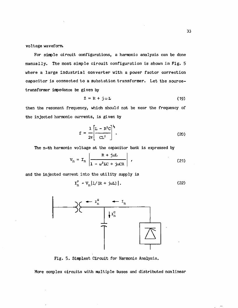
33
v o lta g e waveform.
For sim ple c i r c u i t co n fig u ra tio n s , a harmonic a n a ly s is can be done
m a n u a lly . The most s im p le c i r c u i t c o n f ig u ra t io n i s shown in F ig . 5
w here a l a r g e i n d u s t r i a l c o n v e r te r w ith a power f a c to r c o r r e c t io n
c a p a c i to r i s co n n ec ted t o a s u b s ta t io n tr a n s fo rm e r . L e t th e s o u rc e -
transfo rm er impedance be g iven by
Z = R + j 0) L ( 19)
then the resonan t frequency, which should not be near th e frequency of
th e in je c te d harmonic c u rre n ts , i s given by
h1f = —
2ir
L - R C
CL(20)
The n - th harmonic v o lta g e a t the cap ac ito r bank i s expressed by
R + jo)LV n = I n
1 - (jQ2LC + jioCR
and th e in je c te d cu rren t in to th e u t i l i t y supply i s
Jn = V n l 1/ ^ + j w L ) | .
( 21)
(22)
F ig . 5 . S im plest C irc u it fo r Harmonic A nalysis.
More complex c i r c u i t s w ith m u ltip le buses and d is tr ib u te d n o n lin ea r

34
loads a re b e t te r analyzed by computer. Here, th e sup erp o sitio n p r in c i
p l e can be u sed where harm onics o f d i f f e r e n t o rd e r s a re t r e a t e d s e p a
r a te ly . To i l l u s t r a t e , consider an m-bus power system where harmonic
c u rre n ts are in je c te d a t buses through m as shown in Fig. 6 . Then th e
netw ork e q u a tio n u s in g th e bus im pedance m a tr ix a t th e n - th harm onic
frequency can be w ritte n as
v 1nrT2
V*n
v 1"
11n21n
12n22n
lmn2mn
1ml lm2 „mm
n
i "1
(23)
Techniques fo r assem bling th e impedance m atrix [Z ] , i,j=1 ,2 ,...,m , a re
r e a d ily a v a i la b le in Ref. [21].
From (23), th e n - th harm onic v o l ta g e a t bus k and th e harm onic
c u rre n t flow ing from bus i to bus j a re re s p e c tiv e ly given by
mV1 = E Zlh I hn h = S L n n
and
I 13 = { v 1 - v 3 } / z 1 3 .n n n n
(24)
(25)
10-
20-
POWER
SYSTEMk-lO -
kO-k+lO-
mO-
LinearLoads
N onlinearLoads
F ig . 6 . Power System w ith M ultip le N onlinear Loads.

35
I t i s e v id e n t t h a t th e r e s u l t a n t n - th harm onic v o l ta g e caused by
m u ltip le harmonic sources i s no t on ly dependent on the magnitudes o f
th e cu rren t harmonics o f th e same order but a ls o on th e i r phase ang les.
These p h ase a n g le s can be found from th e l o c a l phase r e l a t i o n s h i p s
betw een th e c u r r e n t harm on ics and t h e i r fu n d a m e n ta ls , a lo n g w ith th e
p hase r e l a t i o n s h i p s betw een th e fu n d am en ta ls a t th e harm onic so u rc e
buses.
The l in e a r approach o f fe rs com putational e ff ic ie n c y w hile g iv in g up
some a cc u ra cy which r e p r e s e n ts th e p rim ary l i m i t a t i o n o f t h i s method.
However, r e c e n t re s e a rc h [43] has shown t h a t th e c u r r e n t i n je c t io n
method i s a d eq u a te where v o l ta g e d i s t o r t i o n f a c to r i s l e s s th a n 10%,
which i s g e n e ra lly th e case. This method has been ap p lied su c c e ss fu lly
to r e a l - l i f e power system s [ 11 ] , [ 2 2 ] and due t o i t s c o m p u ta tio n a l
e f f ic ie n c y , i t i s th e most w idely used to date.

4 . PROBABILISTIC MODELING OF POWER SYSTEM HARMONICS
Power system harmonic a n a ly s is has been c o n v en tio n a lly conducted in
a d e te rm in is tic framework w ith in p u t param eters c o n tro l l in g th e cu rren t
harmonics rep resen ted by fix ed v a lu es . Any random changes in th e h a r
monic c u r r e n t i n j e c t i o n a re th e r e f o r e n o t r e f l e c t e d in th e harm onic
cu rre n t flow s and r e s u l t in g harmonic v o lta g e s . However, i t has been
re c o g n iz e d [16] t h a t power system v o l ta g e and c u r r e n t harm onics a re
tim e -v a rian t due to s to c h a s tic or d e te rm in is tic changes in the opera ting
mode o f n o n lin ea r loads, such as a rc furnaces and v a r ia b le speed d riv e s .
Measurements show th a t th e v a r ia tio n o f harmonic l e v e l s in most networks
i s o ften so e r r a t i c th a t a s in g le reading can be m isleading.
W ith a random c u r r e n t i n j e c t i o n , th e h ig h e s t p o s s ib le harm onic
l e v e l s a re u s u a l l y used in d e te r m in i s t i c p rogram s. T h is p r a c t i c e i s
r e f e r r e d to as th e "w orst c a se method" [5 3 ] . The r e s u l t i n g harm onic
c u rren ts and v o ltag es may occur very r a r e ly (e.g., fo r on ly a few sec -
conds o f th e day) and, th e r e f o r e , may be o f m inor s ig n i f ic a n c e t o h a r
monic assessm ent s tu d ie s . Consequently, s t a t i s t i c a l models o f harmonic
c u r r e n t i n j e c t i o n and p ro p a g a tio n a re h ig h ly d e s i r a b l e f o r a more
r e a l i s t i c p red ic tio n o f harmonic l e v e l s [15], [1 6 ] ,[2 7 ]. P ro b a b i l is t ic
e v a lu a tio n s tak e in to account the v a r ia tio n s o f harmonic c u rren ts and
p rov ide more d e ta i l s than d e te rm in is tic assessem ents. The e x tra in fo r
m ation w i l l a l lo w f i l t e r s and power com ponents in g e n e ra l to be more
e f f e c t iv e ly and econom ically designed.
A number o f th e o re t ic a l s tu d ie s were ded icated to th e summation o f
random phasors w ith re fe ren ce t o harm onics [ 5 4 ] - [ 5 6 ] . However, th e s e
an aly ses are based on th e assumption th a t th e harmonic am plitudes and/or
36

37
t h e i r phase a n g le s a re in d ep en d en t and u n ifo rm ly d i s t r i b u t e d . In Ref.
[5 7 ] , th e random ness o f in je c te d harm onic c u r r e n ts i s t r a c e d back to
changes in th e v a r i a b l e p a ra m e te rs g o v e rn in g th e o p e ra t in g modes o f
n o n lin ea r loads. Other p u b lic a tio n s have in v e s t ig a te d th e p ro b a b ili ty
c h a r a c te r is t ic s o f harmonic in je c t io n g e n e ra te d by some s p e c i f i c non
l i n e a r lo a d s (NLs), in c lu d in g t r a c t i o n d r iv e s [58], e l e c t r i c v e h ic le
b a t t e r y c h a rg e rs [1 7 ] , TV r e c e iv e r s and l i g h t dimmers [1 8 ] , and d .c.
d r iv e s [19].
In th e m ost g e n e r a l c a s e , th e NLs may have d i f f e r e n t r a t in g s and
opera ting modes which a re e i th e r d e te rm in is tic o r n o n -d e te rm in is tic in
n a tu re . In a d d i t io n , th e c o n f ig u ra t io n o r sw itc h in g s t a t e o f NLs con
n e c te d t o a common bus may be f ix e d , d e t e r m i n i s t i c a l l y , o r random ly
vary ing w ith time.
In t h i s chap ter, a p r o b a b i l i s t ic model fo r harmonic a n a ly s is [59] i s
proposed where in je c te d harmonic c u r r e n ts may be p a r t l y d e te r m in is t i c
and p a r t ly random. A c la s s i f ic a t io n o f harmonic generato rs, depending
on th e i r opera ting mode and sw itching s ta t e , i s g iven f i r s t . Then, based
on some re a s o n a b le a ssu m p tio n s , a g e n e ra l p ro c e d u re i s p re s e n te d t o a
harm onic c u r r e n t i n j e c t i o n which i s p a r t l y d e te r m in is t i c and p a r t l y
random fo r a bus having NLs o f d if f e r e n t c a teg o rie s . This i s fo llow ed
by a p r o b a b i l i s t i c model o f th e harm onic c u r r e n t p ro p a g a tio n and th e
r e s u l t i n g harm onic v o l ta g e s . The p ro c e d u re i s d em o n stra ted by a
d e t a i l e d exam ple which i l l u s t r a t e s th e p r o b a b i l i t y a s p e c ts o f power
system harmonics. L a s tly , p o te n t ia l a p p lic a tio n s o f th e p r o b a b i l is t ic
model a re a ls o considered.

38
4.1 C la s s if ic a t io n o f N onlinear Loads
In g e n e r a l , a d i s t r i b u t i o n bus has n o n l in e a r lo a d s o f d i f f e r e n t
types, o f n o n lin e a r ity , o p e ra tio n a l inodes and ra tin g s . Some loads, once
sw itched on, o p era te s te a d i ly (f lu o re sc en t lamps), o th e rs vary slow ly
and d e te rm in is t ic a l ly w ith tim e (b a tte ry chargers), w h ile the r e s t a re
n o n d e te r m in is t ic in n a tu re (a rc w e ld e rs ) . F u rth e rm o re , th e lo a d
s w itc h in g s t a t e ( i . e . , th e c o n f ig u ra t io n o f NLs in s e r v ic e ) may a l s o
vary d e te rm in is t ic a l ly or randomly.
For each ty p e o f th e NLs, l e t th e s t a t i s t i c a l d a ta o f th e random
v a r i a b l e s (p a ram e te rs g o v e rn in g th e o p e r a t io n a l modes and sw itch in g
s t a t e o f th e NLs) be known. These s t a t i s t i c a l d a ta may be determined by
re c o rd in g a la r g e volum e o f in fo rm a tio n re g a rd in g th e changes o f th e
random v a r ia b le s fo r a s u f f ic ie n t ly long period o f tim e. In g en era l, i t
i s d e s i r a b l e to know th e tim e i n t e r v a l o f th e day when th e h ig h e s t
harmonic l e v e l s occur. T herefore, i t i s suggested to d iv id e th e d a ily
(or weekly) c y c le in to a f i n i t e number o f in t e r v a l s whose dura tions may
be o f th e o rd e r o f m in u tes o r h o u rs , and d e f in e PDFs o f th e random
v a r ia b le s a t each tim e in te r v a l .
In each tim e in te r v a l , th e n o n lin ea r loads w i l l generate cu rren ts
which can be d iv id ed in to four ca teg o rie s :
1. a d e te rm in is tic number o f d e te rm in is tic cu rren ts (DNDC),
2. a random number o f constan t c u rren ts (RNCC),
3. a constan t number o f random c u rre n ts (CNRC), and
4. a random number o f random c u rren ts (RNRC).
In g en era l, a d is t r ib u t io n bus con tains n o n lin ea r loads o f a l l o f
th e above c a te g o r ie s . At any i n s t a n t , th e t o t a l harm onic c u r r e n t
in j e c te d a t t h a t bus i s a summation o f a d e te r m in is t i c and a random

39
harmonic cu rren t component. The t o t a l p ro b a b il i ty den sity function o f
th e random harmonic component i s derived in th e fo llo w in g sec tion .
4.2 P ro b a b ility D is tr ib u tio n o f Harmonic In je c tio n
Before modeling a harmonic cu rren t in je c tio n d e te rm in is t ic a l ly and
p r o b a b i l i s t i c a l ly , a number o f assumptions must f i r s t be made:
1. th e n o n lin ea r loads vary independently from each o th e r,
2. th e p ro b a b il i ty c h a ra c te r is t ic s o f the randomly varying NLs a re
re a d i ly avai la b le ,
3 . th e r a te o f change in th e number o f n o n lin ea r loads in s e rv ic e i s
low r e l a t i v e to th e random change in the opera ting mode o f NLs,
4. both th e l in e and e q u iv a le n t l in e a r load impedances are tim e-
in v a r ia n t,
5 . th e d is tr ib u tio n system i s sym netrical and in balanced opera ting
c o n d i t io n , c o n se q u e n tly , l im i t i n g th e a n a ly s i s to th e s i n g l e
phase case, and
6 . th e system i s o p era ting in a qu asi-stead y s ta t e condition (the
opera ting modes o f th e NLs vary s u f f ic ie n t ly slow such th a t th e
r e s u l t in g e l e c t r i c a l t r a n s ie n ts a re n e g lig ib le ) .
The f i r s t assumption i s somewhat q u estio n ab le s in ce th e re may be a
c o r re la t io n between th e o p era tin g mode v a r ia tio n s and sw itching s ta te s
o f the n o n lin ea r loads (e.g., th e sequence o f o pera tions in a s te e l m i l l
or any process l in e ) . In g en era l, however, th ese c o r re la tio n s are not
w e ll defined . Concerning th e second assumption, s t a t i s t i c a l data fo r
n o n lin ea r loads a re ra re a t th e p resen t tim e, so th a t th e PDFs fo r most
loads a re not r e a d ily a v a i la b le . But the need fo r such im portant in fo r
mation has been re p e a te d ly voiced [16]. I t i s th e re fo re expected th a t

40
th ese s t a t i s t i c a l data w i l l be a v a i la b le in th e near fu tu re considering
t h a t s u i t a b l e in s tru m e n ta t io n to re c o rd such d a ta i s b e in g d ev e lo p ed
[6 0 ] . The rem a in in g assu m p tio n s a re made p r im a r i ly to red u ce th e
com plexity o f th e problem.
C o n sid e r th e lo a d a rran g em en t o f a d i s t r i b u t i o n fe e d e r in F ig . 7,
where the load u n its a re numbered in each n o n lin ea r load category. Note
th a t th e l in e a r load (LL) may a ls o in c lu d e cap ac ito rs fo r power fa c to r
co rre c tio n . The t o t a l n - th o rder harmonic c u rren t phasor a t any time
i s given by
w ith
*»<*> = m=l
= , £, h n i V <28)1=1
h n ' V = * <29)ies,h
h * ™ - . 1 h m ™ <30)1=1and
W * 1 " * <3D
where I .(t) denotes the n -th harmonic cu rren t in je c te d by load u n it immo f NL c a te g o ry m ( a l l i n j e c t e d c u r r e n ts m ust be d e f in e d r e l a t i v e t o a
common phase r e f e r e n c e ) . Sh and w i l l be f u r th e r d e f in e d in t h i s
s e c tio n .
E q u a tio n (27) shows th e n - th harm onic c u r r e n t composed o f fo u r
com ponents. O nly th e f i r s t com ponent, i s d e te r m in is t i c in
n a tu re , so th a t th e p ro b a b il i ty aspect a p p lie s e x c lu s iv e ly to th e th re e
rem aining components defined in (2 9 )-(3 1 ). The p r o b a b i l i t y c h a r a c te r -

41
i s t i c s o f each cu rren t component w i l l be found s e p a ra te ly , from which
th e PDF o f th e t o t a l random cu rren t can then be deduced.
A
A
zfl m1 g
DNDC
1 kCNRC
- j > LL
A1 h
RNCC
t a n ™
A1 I
RNRC
F ig . 7 . Load Composition.
> NLs
A two-dim ensional random vecto r can be described by e i th e r the jo in t
d e n s i ty fu n c tio n o r th e m a rg in a l d e n s i ty fu n c tio n s o f i t s r e a l and
imaginary p a r ts (x-y p ro je c tio n s) . In t h i s paper, the l a t t e r d esc rip
tio n i s chosen because th e convo lu tion process can be re a d ily ap p lied in
o b ta in in g the d is tr ib u tio n o f th e summation o f r e a l random v a r ia b le s .
Hence, a tim e-dependent complex n - th harmonic cu rren t generated by
load u n it i o f NL category m w i l l g e n e ra lly be w ritte n as
I . ( t ) = X . ( t ) + j Y . ( t ) . m m m ni J m ni
In th e d e riv a tio n s th a t fo llo w , both th e r e a l p a r t X . and imaginary' m ni
p a r t Y . o f each harm onic c u r r e n t in a tim e i n t e r v a l w i l l be deno ted m ni
by W . u n le ss otherw ise s ta te d .J m ni

4.2.1 Sum o f Random Number o f Constant C urrents
Define th e sample space Sh to be th e c o l le c t io n o f a l l p o s s ib le NL
co n fig u ra tio n s in th e RNCC category, i .e .,
Sh = *T1' V Th’}
where h ’ may assume a v a lu e between 2 h ( i f a l l h NLs are d if f e r e n t from
each o th e r) and h+1 ( i f a l l h NLs a re id e n t ic a l ) . The symbol Tj d esig
n a tes some sw itch ing s t a t e o f th e RNCC load category. The p ro b a b i l i t ie s
a sso c ia ted w ith each sw itch ing s ta t e a re given by
P { T j } — P f j f j = 1 f 2 , . . . , h f .
Therefore, S h c o n s ti tu te s a p ro b a b il i ty space o f a l l p o ss ib le sw itching
s ta te s o f th e RNCC load category , and th e random v a r ia b le s X„ and Y„2 n 2n
can be defined in Sh to a sso c ia te re s p e c tiv e ly th e r e a l and imaginary
p a r ts o f th e r e s u l t in g harmonic cu rren t w ith each x r .
W2n (Tj ) = w j '
where Wj i s th e sum o f r e a l (im ag in a ry ) p a r t s o f th e n - th harm onic
c u rre n ts generated by th e energized NLs designated by T j. Recognizing
th e d is c re te n a tu re o f T j, th e PDF o f th e x-y p ro jec tio n s o f th e cu rren t
I 2n( t ) g iv e n in (29) i s
P™ (Wj) — p_ , j = 1 , 2 , . . . , h ' . (32)" 2n J u
4.2.2 Sum o f Constant Number o f Random C urrents
In t h i s category , th e harmonic c u rre n ts change randomly whereas th e
number o f harm onic s o u rc e s , k, i s c o n s ta n t . L e t ou, i= 1 ,2 ,. . .k , r e p r e
s e n t th e v a ry in g p a ra m e te r (e .g ., f i r i n g a n g le in c a se o f p h a se -
c o n tro l le d r e c t i f i e r s ) governing th e random o p era ting modes, and assume
th e PDF o f a . , p . . (a), f o r each NL o f t h i s c a te g o ry to be known.i u i
Considering th a t the x-y p ro je c tio n s o f a harmonic cu rren t as func

43
tio n s o f th e v a r ia b le param eter can g e n e ra lly be deduced, l e t
and
X , . = F_ . ( a . ) 3nx 3ni x
Y . . = G , . ( a . ) 3nx 3nx x
be known. Then th e PDFs o f X3ni and Y3ni are g iven by [61]
Pw (w) = Pa [H -^ . (w) ] IdH "^ (w)/dw|, (W ,H) = ( X , F ) , (Y ,G ) (33)3n i i
w here H3^\ r e p r e s e n ts th e in v e r s e fu n c tio n o f H3 n i. I t i s p o in te d o u t
th a t equation (33) a p p lie s on ly when F3n± and G3ni are s t r i c t l y monoto
nous. I f t h i s i s n o t th e c a se , e q u a tio n (33) can s t i l l be a p p l ie d to
s e v e ra l in te r v a l s o f where F 3ni and G3ni are s t r i c t l y monotonous in
each in te r v a l . The PDFs in th e in d iv id u a l in te r v a l s a re then added
a t th e corresponding v a lu es o f X3ni and Y3ni.
C onsidering equation (30), th e PDF o f the r e a l o r imaginary p a r t o f
I 3n( t ) i s
<3*>
where th e a s te r is k rep resen ts th e s tandard co nvo lu tion in te g r a l . I t i s
noted th a t th e mean and variance o f th e r e s u l t in g d is t r ib u t io n o f equa
t io n (34) can be computed from
ky W = Z y w3n i = l 3niand
ka 2 £ a 2w w3n i = l 3ni
where . and . r e s p e c tiv e ly rep resen t th e mean and variance o f
th e harmonic c u rren t p ro je c tio n g e n e ra te d by th e i - t h n o n l in e a r lo a d .
These param eters are defined by

44
yw = W P (w)dw (35)3ni •L°° 3ni
and
°W, . ‘ I < "->■ «, _ > V . fw ,aw - (36)3 m J*°° 3ni 3ni
In p a r t ic u la r , i f th e n o n lin ea r loads o f th i s category a re id e n t ic a l ly
d i s t r i b u t e d and k i s s u f f i c i e n t l y la r g e , th e c e n t r a l l i m i t theorem
s t r o n g ly s u g g e s ts t h a t p (w) app roaches a G aussian d e n s i ty fu n c tio n3n
given by [61]
p„ (w) = ---------— exp3 n C L , /2TTk
w3ni
K " klS „ i
2ka2w3ni
(37)
where and a 2 re p re sen t the mean and variance o f a s in g le load.w3ni w3ni
4.2.3 Sum o f Random Number o f Random Currents
The f in a l c u rren t category to be considered i s given in (31) where
both I 4 n i( t) , i =1,2,..., and th e load sw itching s ta t e a re random v a r ia
b le s . As in th e CNRC case, l e t Bi be the random v a r ia b le governing the
o p e ra t in g mode o f th e i - t h n o n l in e a r lo a d o f t h i s c a te g o ry w ith a PDF
d eno ted by pg . (B).
The PDF o f th e r e a l o r im ag inary p a r t o f th e c u r r e n t g e n e ra te d by
th e i - t h n o n lin ea r load i s computed in th e same fash ion as fo r th e CNRC
c a te g o ry by e q u a tio n (33), where th e s u b s c r ip t s o f W and H h ave to be
modified from 3ni to 4ni to r e f e r to th e RNRC category.
Now, l e t th e sample space o f a l l p o s s ib le NL con fig u ra tio n s o f th e
RNRC category be designated by
S£ = *vl ' v2 ' * •' ' vi,’ where r e p r e s e n ts some sw itc h in g s t a t e o f th e RNRC c a te g o ry and £-*
Aassumes a v a lu e between 2 ( i f a l l £ NLs a re d if f e r e n t from each o ther)

45
and. £+1 ( i f a l l I NLs a re id e n tic a l) . Supposing th e p ro b a b i l i t ie s o f
th e s w itc h in g s t a t e s v^, j= 1 ,2 ,...£ ’, to be known, th e n
P {v .} = p , j = l , 2,3
S in ce th e r a t e o f change in th e lo a d sw itc h in g s t a t e i s assumed t o be
low r e l a t i v e t o th e change in th e o p e ra t in g mode, th e n , g iv e n ,
f in d in g th e PDFs o f th e x -y p r o je c t io n s o f th e t o t a l c u r r e n t in
sw itching s t a t e v.. i s id e n t ic a l to f in d in g th e t o t a l PDFs fo r th e CNRC
load category in th e p rev io u s subsection . Thus, th e c o n d itio n a l PDF,
p^. (w ),of th e r e a l o r im ag in ary p a r t o f th e t o t a l n - th harm onic c u r - 411
r e n t g e n e ra te d by th e NLs in each o f th e sw itc h in g s t a t e s can be
computed as in (34) r e s u l t in g in the PDFs o f the x-y p ro je c tio n s of
I 4n( t) fo r a l l p o ss ib le sw itching s ta te s as fo llo w s:
£ 1p (w) = E p p^ (w) (38)
4n j=1 Vj 4n
4.2.4 R esu ltan t n - th Harmonic Current In je c tio n
The t o t a l n - th harm onic c u r r e n t in je c te d i s composed o f a d e te r
m in is tic p o rtio n and a random p a r t . The random p a r t i t s e l f i s a summa
t io n o f th r e e te rm s whose p r o b a b i l i s t i c m odels h ave a l r e a d y been
derived . Furthermore, s in ce th ese terms a re considered to be independent
o f each o th e r , bo th th e r e a l and im ag in ary p a r t s o f th e t o t a l n - th
harmonic random c u rren t a re given by
Pw = P W * Pw * pw (39)n 2n 3n w4n
where p., (w), pI7 (w) and pu (w) a re r e s p e c tiv e ly taken from equations w2n w3n w4n
(32), (34) and (38).
N oting t h a t th e m agnitude o f I n i s found from | l n | = (Xn + )£) , th e
PDF o f | I n | can be computed stepw ise as fo llo w s:

46
1. F in d th e PDF o f X* and Y* u s in g
Pw2 (w) = {pw (y(7) + pw (-vG?) } / 2 v f c . (40)n n n
2. Measurements show th a t X* and Y* o f th e h igh frequency harmonic
c u r r e n ts ( g r e a te r th a n o r e q u a l to th e f i f t h o rd e r ) a re p r a c t i
c a l l y in d ep en d en t [5 8 ] . T h is can be re c o g n ize d from th e f a c t
th a t any sm all changes in th e fundamental components causes very
e r a t ic changes in th e h igher order components. The p ro b a b il i ty
den sity function o f th e sum X* and Y* can be approximated by
Px2+Y2 — Px2 * Py2 * (41)n n n i n
3. Noting th a t | I n | i s th e square ro o t function o f X* + Y*, the
PDF o f | I n | i s computed by using
p l | (i> = 2 (i> p ^ t a n . r e )1 n 1 n n
The mean and v a r ia n c e o f | I n | a re computed from (35) and (36) a f t e r
re p la c in g w and PW;Jni by |I n | and p ^ |.
The e x p re s s io n f o r I l n ( t ) in (28) and th e PDFs in (39) and (42)
provide a com plete model o f th e n -th harmonic cu rren t in je c tio n a t each
bus con tain ing n o n lin ea r loads.
4.3 P ro b ab ility D is tr ib u tio n o f Harmonic Propagation
The e f fe c t o f nonsinuso idal v o lta g e on harmonic cu rren t in je c tio n in
c o n v e r te r i n s t a l l a t i o n s has been analyzed fo r s te a d y -s ta te conditions
[44]. To attem pt to in co rp o ra te s im ila r consid era tio n s in random s i tu a
tio n s would le ad to an unaccep tab le degree o f com plication. F u rth e r
more, th e e f f e c t o f v o l ta g e d i s t o r t i o n f o r most n o n l in e a r lo a d s i s o f
secondary o rder i f th e v o lta g e d is to r t io n fa c to r i s le s s th a t 10% [43].

and
In th e fo llo w in g , th e in je c te d harmonic cu rren ts a re th e re fo re assumed
to be independent o f th e v o lta g e waveform.
An m-bus power system where harmonic c u rren ts a re in je c te d a t buses £
th ro u g h m as shown in F ig . 6 , can be d e sc r ib e d by an m -th o rd e r s e t o f
l in e a r complex a lg e b ra ic equations fo r each harmonic o rder under con
s id e ra tio n . The d e te rm in is tic p a r t o f th e n -th harmonic bus v o ltag es
and c u rre n ts a re computed by equations (25) and (26).
To f in d th e PDFs o f th e r e a l and im ag in ary p a r t s o f th e random
co m p o n en ts o f V ^ t) and I^k( t ) , l e t
Vn * ^ + Rn '
I ik = Xlk + j Ykkand ", n. "
Z = Slk + j T1 .n n J n
k xkThen th e r e a l and imaginary p a r ts o f Vn and I n can be expressed as
Qk = ? ( s f / - T ; V ) ,i= fl, n n
Rk = ? ( S ^ Y 1 + T i k X i ) , n i=£> n n n n
X *k = { S f « £ - Qk) + T j k (R * - Rk ) } / { (S^k ) 2 + (T^k ) 2 }
Y * k = {sJ-k U £ - Rk ) - T ^k (Q^ - Q „ ) > / { ( s ^ k ) 2 +n n n n n n n n
Noting th a t th e p ro b a b il i ty den sity func tions o f the x-y p ro je c tio n s
o f I n( t) have a lread y been obtained by equation (39), and considering
th a t X^k and Y ^k a re p r a c t ic a l ly independent fo r h igher o rder harmonics,
th e PDFs o f Qk, Rk, X*k and Y*k in (43)—(-46) a re r e s p e c t iv e ly g iv e n by
(43)
(44)
i k >2} (45)
f > * } . (46)

n n ° n bn
48
( 48)
and
p x i k - <C2 C3 ) 2 ( W )
P Yi k = (C 2c 3 ) 2 p s i (| a ) . p e k ( i ) . p E i ( i ) . PRk ( = E ) { 5 0 )
mwhere
C1 = " V I ' C2 = Sf /{ {Snk) 2+ (Tnk) 2}' C3 = TT / { (Snk) 2+ (Tnk) 2 } *
From th e above p ro b a b il i ty den sity func tions, th e PDF o f th e n -th
harmonic v o lta g e magnitude a t any bus can be obtained by th e same pro
cedure described in (40)-(42). The same arguments ho ld fo r th e harmonic
cu rre n t p ro p ag a tio n s.
4.4 Computational Methods
A method to compute a PDF composed o f a c o n v o lu tio n o f s e v e r a l
com ponents, p i (w), i= 1 ,2 ,... ,N , as in e q u a tio n s (34), (39) and (4 7 )-
(50) i s by f i r s t fin d in g th e c h a r a c te r is t ic function (Fourier transform )
o f each component in v o lv ed :
F .(a ) = p. (w) exp(jaw)dw, i = l , 2 , . . . , N (51)■ i
The o v e ra l PDF i s then found by tak in g th e in v e rse F o u rie r transform
.00 N
PW(W> ■ 2TT { II F. (a) exp(-jw a)}da (52)00 i = l 1
In g e n e r a l , how ever, th e in t e g r a t i o n s in e q u a tio n s (51) and (52) a re
r a th e r d i f f i c u l t to e v a lu a te a n a ly t ic a l ly since only a lim ite d number o f
flinctions have th e i r F o u rie r transform s re a d ily a v a i la b le . In ad d itio n ,
p ±(w), i=1,2,...,N , a re g e n e ra lly s to red in num erical form.
In p r a c t i c e , w here th e PDFs o f th e r e a l and im ag inary p a r t s o f

49
harm onic c u r r e n ts can n o t be approxim ated by a n a ly t ic a l fu n c tio n s , the
F o u rie r transfo rm method i s no t o f p r a c t ic a l v a lu e . Even i f th e F ourier
transform o f each PDF cou ld be defined a n a ly t ic a l ly , th e t o t a l PDF would
be v e ry d i f f i c u l t ( i f n o t im p o s s ib le ) to o b ta in from th e r e s u l t a n t
F o u r ie r tra n s fo rm . T h is i s p a r t i c u l a r l y t r u e when a number o f non
id e n t ic a l loads a re in v o lv ed .
There a re two p r a c t ic a l computation methods to e v a lu a te th e PDFs of
the random harmonic c u rren ts and v o lta g e s : 1) d ire c t in te g ra tio n using
convo lu tion and 2) Monte C arlo s im u la tio n , both o f which are performed
by computer. Each method has in h eren t advantages and d isadvantages. In
th e f i r s t method, a number o f d if f e r e n t num erical a lgorithm s are a v a i l a
b le to compute the co nvo lu tion in te g r a l fo r determ ining th e r e s u l ta n t
d is t r ib u t io n [62]—[633. This method re q u ire s r e l a t i v e l y le s s computa
t io n tim e, but may in troduce la rg e in te g ra tio n e r ro rs due to the e r a t ic
(no t sm ooth) PDFs o f th e random harm onic c u r r e n ts . F ig u re 8 shows a
flow chart o f the num erical in te g ra tio n method.
The Monte C arlo s im u la tio n method u t i l i z e s repeated t r i a l s , the
c o l le c t io n o f which can be used to estim ate th e p ro b a b il i ty d is t r ib u
t io n . T h is method h as r e c e n t ly been a p p l ie d t o a v a r i e ty o f com plex
power system problems [6 4 ]-[6 5 L However, one problem w ith th e Monte
C a r lo s im u la t io n i s th e r e l a t i v e l y la rg e computation tim e and memory
req u ired to o b ta in r e s u l t s w ith s a t i s f a c to ry accuracy. F igure 9 i l l u s
t r a t e s in f lo w c h a r t form th e Monte C a r lo method f o r d e te rm in in g th e
r e s u l ta n t PDFs o f harmonic c u rren t in je c t io n and propagation.
4.5 Example and D iscussion o f R esu lts
Let an a n a ly s is be d esired o f th e 5 -th o rder harmonic cu rren ts and

50
v o l ta g e s o f a h y p o th e t ic a l 3-bus d i s t r i b u t i o n system shown in F ig .
10(a), where a l l impedance v a lu es are in p e r-u n it va lu es . The eq u iv a len t
c i r c u i t f o r th e 5 - th harm onic i s shown in F ig . 10(b) where th e r e
s is ta n c e s and inductances are assumed to be frequency-independent.
n > N?
STOP
P lo t PDFs and update harmonic o rder
For each bus, compute pw ,pw ,Pw and pw
Compute pnk , PRk , pxk and pYk , ■ n n n
Compute magnitude o f n -th harmonic cu rren t and vo ltage a t each bus (Eqns. (40)—(42))
For each bus define: Pt j , j = 1 , 2 , . . . , h 'P a i , i= 1 , 2 , . . . ,kP $ i > »2, • • • , ^ tPv-; > j = » 2 , • • • , ^
F ig . 8 . Flowchart o f In te g ra tio n Method.
Since l i t t l e r e le v a n t da ta on load and harmonic p ro b a b ili ty charac
t e r i s t i c s c o u ld be found in th e l i t e r a t u r e , an a r b i t r a r y ch o ice o f
d i f f e r e n t lo a d c h a r a c t e r i s t i c s was made. The n o n l in e a r lo a d s a t bus 3
form a combination o f a l l c a teg o rie s defined e a r l i e r but, fo r s im p lic i
ty , i t i s assumed t h a t a l l NLs o f each c a te g o ry a re i d e n t i c a l . The
fo llo w in g s t a t i s t i c a l data o f the n o n lin ea r loads may not be ty p ic a l ly

51
r e a l i s t i c , bu t w i l l i l l u s t r a t e th e gen era l technique th a t was developed
and which i s th e prim ary purpose o f th is study.
STOP
Do M i te r a t io n s
Evaluate Histograms
Compute W
P lo t histogram s and update Harmonic o rder
Compute magnitude o f n -th harmonic cu rren t and voltage a t each bus
For each bus d e fine : Pt j > »2»• • • »h*Pa± » i= 1 » 2 , . . . ,kPSi * i = “\ , 2 , • • • tHPv-i »
For each bus, generate th e follow ing:
F ig . 9 . Flowchart o f Monte Carlo Sim ulation Method.
4.5.1 S t a t i s t i c a l Data o f N onlinear Loads
1. DNDC c a te g o ry - Three ac/dc co n v erte rs a re switched ON from 7am to
5pm, each g e n e ra t in g a s te a d y 5 - th harm onic c u r r e n t I 5 = 5A w ith z e ro
phase ang le (re fe rred to th e p o s i t iv e zero c ro ssin g o f th e fundamental
v o ltag e ). In ad d itio n , an e l e c t r i c v e h ic le b a tte ry charger i s turned ON

52
a t m idnight, then rep laced by another every 8 hours. A ty p ic a l b a tte ry
c h a rg e r g e n e ra te s a 5 - th harm onic c u r r e n t whose m agnitude and phase
an g le vary during the recharge cy c le as shown in Fig. 11 [17].
220 V, 0 1 + j .0313 .8 kV
.1+j .5j . 05>NLs
. 0 1 + j .03. 0 2 + j .04. 0 2 + j .04
.05+j .15
1 kVA @ 1PF1 kVA @ 1PF
BASE I3VA: 40kVA20 kVA @ . 5PF
(a)
j 2 .65 .11
vY V N — W ' ---------( 2 } j . 3 5 .03
— 7 V - / Y W A A A. 02
j 7 .07 .18- j .56
1 .41.05
(b)
F ig . 10. Three-Bus D is tr ib u tio n System: (a) One-Line Diagram,(b) E quivalent C irc u it fo r 5 -th Harmonic.
2. RNCC category - There a re 50 f lu o re sc e n t lamps each generating a 5-
th harmonic c u r r e n t o f .07% o f th e fu n dam en ta l (=; 0.12A f o r a 240V/400W
lamp), w ith zero phase ang le [66]. The p ro b a b il i ty den sity function o f

53
the number o f lamps switched ON i s binom ial,
p = p1 (1 -p ) 5 0 - i i= 1 ,2 50, (53)
w here p = .85 d u rin g b u s in e s s h o u rs (7am - 5pm), and p = .25 f o r th e
r e s t o f th e day.
F ig . 11. 5 -th Harmonic Current Generated Typical B attery Charger.
3 .CNRC c a te g o ry - Between 7am and 5pm, 25 p h a se -c o n tro lle d r e s i s t i v e
loads are in s e rv ic e , each o p era ting a t 240V/400W, w ith a f i r in g ang le
vary ing randomly and uniform ly between 55° and 70°. The r e a l and imagi
nary p a r ts o f th e 5 -th harmonic cu rren t generated by th i s type of load
a re re s p e c tiv e ly given by
4. RNRC c a te g o ry - In a d d i t io n t o th e 25 p h a s e - c o n t r o l le d r e s i s t i v e
lo a d s above, th e r e a re 10 more u n i t s o f t h i s lo a d , b u t t h i s number
OOoo
o. a.CD
°t).00 1-60 3.20 80T I M E ( H O U R S )
6 . 4 0 8 . do
andX5 = 5{2 s in (6a) - 3 s in (4a)} /36 ir a
Ys = 5{2 cos(6a) - 3 cob(4c0}/36tt a .

v a r i e s random ly w ith a u n ifo rm d i s t r i b u t i o n (pv_. = 0 .1 , j= 1 ,2 ,...1 0 )
from noon to m idnight. Otherwise, th e f i r in g ang le $ v a r ie s in th e same
fa s h io n a s a .
4.5.2 S im ulation R esu lts and D iscussion
From th e s t a t i s t i c a l d a ta g iv e n abo v e, i t i s seen t h a t th e 2 4 -h r
p e r io d can be composed o f fo u r tim e i n t e r v a l s . Each i n t e r v a l has th e
fo llo w in g combination o f n o n lin ea r load ca teg o rie s :
1. [12pm, 7am] - {DNDC, RNCC}
2. [7am, 12am] - {DNDC, RNCC, CNRC}
3. [12am, 5pm] - {DNDC, RNCC, CNRC, RNRC}
4. [5pm, 12pm] - {DNDC, RNCC, RNRC}
For each tim e i n t e r v a l , th e p r o b a b i l i t y d e n s i ty fu n c t io n s o f th e
r e a l and im ag in ary p a r t s o f th e 5 - th harm onic c u r r e n t i n j e c t i o n were
computed by num erical in te g ra tio n o f equations (39), and were v e r if ie d
by th e Monte C arlo s im u la tion . F igure 12 shows th e se d is tr ib u tio n s fo r
th e 2nd, 3 rd and 4 th tim e i n t e r v a l s . In th e f i r s t tim e i n t e r v a l , th e
random component o f th e imaginary p a r t i s zero but th a t o f th e r e a l p a r t
i s d is c r e te in n a tu re and i s described by equation (53).
Note th a t a l l th e d is t r ib u t io n s approach a normal den sity function
(shown in do ts) except fo r th e imaginary p a r t in the 4 -th tim e in te r v a l .
T h is component i s g e n e ra te d o n ly by th e RNRC lo a d c a te g o ry fo r which
the c e n tr a l l im i t theorem cannot be ap p lied s in ce the number o f loads
changes randomly. Fig. 13 shows th e d is tr ib u tio n s o f th e random compo
nent o f the 5 -th harmonic cu rren t magnitude computed by using equations
(4 0 )-(4 2 ). The d o ts show th e r e s u l t s o b ta in e d by th e Monte C a r lo
method.

55
oCM
h-ODC00crd 'Q_
CEUJoCC=J*u_□CL.
OO1 2 . 0 01 0 . 0 08 . 0 04.00 6.00
R E R L P R R T ( R M P S )2 . 0 0. 0 0
Li_□Q_
CDO7.20. 0 0 1 . 2 0 2 .40 3.60
I M R G . P R R T ( R M P S )6 . 0 0
(b)
F ig . 12. PDFs o f (a) Real and (b) Imaginary P a rts o f 5 -th Harmonic C urrent in Time In te rv a ls 2, 3 and 4.
A param eter o f in te r e s t in th e a n a ly s is o f random harmonic cu rren ts
i s th e expected v a lu e . The expected v a lu es o f the x-y p ro je c tio n s
fo r th e 5 -th harmonic c u rren t were computed fo r each time in te r v a l and
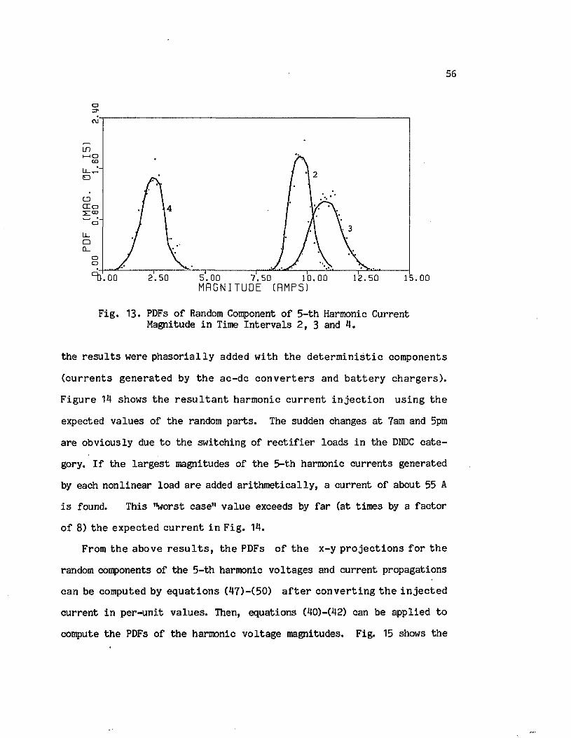
56
o
moCO
D
CDl as:co
oLl .□Cl.
oo2.50 5.00 7.50
M A G N I T U D E ( R M P S ). 0 0 1 0 . 0 0 12.50 15.00
F ig . 13. PDFs o f Random Component o f 5 - th Harmonic Current Magnitude in Time In te rv a ls 2 , 3 and 4.
the r e s u l t s were p h a s o r ia l ly added w ith th e d e te r m in is t i c com ponents
( c u r r e n ts g e n e ra te d by th e ac -d c c o n v e r te r s and b a t t e r y c h a rg e rs ) .
F ig u re 14 shows th e r e s u l t a n t harm onic c u r r e n t i n j e c t i o n u s in g th e
expected va lu es o f th e random p a r ts . The sudden changes a t 7am and 5pm
a re obv io u sly due to th e sw itching o f r e c t i f i e r loads in th e DNDC c a te
gory. I f th e la rg e s t magnitudes o f th e 5-t.h harmonic cu rren ts generated
by each n o n lin ea r load a re added a r i th m e tic a l ly , a cu rren t o f about 55 A
i s found. This "worst case" v a lu e exceeds by f a r (a t tim es by a fa c to r
o f 8) th e e x p ec te d c u r r e n t in F ig . 14.
From th e above r e s u l t s , th e PDFs o f th e x -y p r o je c t io n s f o r th e
random components o f the 5 -th harmonic v o lta g e s and c u rre n t propagations
can be computed by e q u a tio n s (47)-(50) a f t e r c o n v e r t in g th e in j e c te d
cu rre n t in p e r -u n it v a lu e s . Then, equations (40)-(42) can be ap p lied to
compute th e PDFs o f th e harmonic v o lta g e magnitudes. Fig. 15 shows the

57
PDF o f th e random component o f th e 5 - th harm onic v o l ta g e m agnitude a t
bus 3 (v e r if ie d by th e Monte C arlo method in dots). O ther inform ation,
such as ex p ec ted v a lu e s , maximum and minimum harm onic v o l ta g e s and
c u r r e n t s , c o u ld a l s o be o b ta in e d from th e above r e s u l t s .
a.oo .oon
LlJ
o_
CDcr
oCD
. 0 0 4.00 8 . 0 0 T I
1 2 . 0 0 T I M E ( H O U R S )
16.00 2 0 . 0 0
F ig . 14. Expected Value o f 5 -th Harmonic C urrent Versus Time.
ID
LD,
D
Ll-CUQ_
oCD
. 00 0.38 0.75 1.13M A G N I T U D E '/. ( P . U . )
1.50 1.88 2.25
F ig . 15. PDFs o f Random Component o f 5 -th Harmonic Voltage Magnitude a t Bus 3 in Time In te rv a ls 2 , 3 and 4

58
4.6 P o te n tia l A pp lications
Accurate p re d ic tio n o f power system harmonic behavior w i l l provide
im portant inform ation to u t i l i t y companies and equipm ent d e s ig n e rs .
A few o f th e p o t e n t i a l u se s o f th e p r o b a b i l i s t i c model o f harm onic
cu rren t in je c t io n and propagation a re described below.
4.6.1 S e ttin g L im ita tions on Harmonic L evels
In th e fu tu re , harmonic l e v e l s a re expected to in c rease to in to le r a
b le l e v e l s . S ev e ra l in d u s tr ia l iz e d co u n trie s have a lread y e s ta b lish e d
some standards [67 ]-[6 8 ], but th e re i s no uniform sp e c if ic a tio n on the
maximum p e rm iss ib le amount o f wave d is to r t io n fo r cu rren t and v o ltag e .
F u rth e rm o re , e x i s t in g r e g u la t io n s g e n e r a l ly do n o t r e f l e c t harm onic
v a r ia tio n s and th e i r randomness in power systems, and i t i s in c re a s in g ly
b e in g re c o g n ize d th a t more co m p le te and a c c u ra te recom m endations on
a llo w ab le harmonic l e v e l s are needed.
For example, re fe ren ce [27] s e ts a l im it o f 5% t o t a l v o ltag e d is to r
t io n fo r gen era l in d u s t r ia l power systems a t 2.4 to 69 kV. A re le v a n t
question i s , "what i f th e p ro b a b ili ty o f th e d is to r t io n fa c to r exceeding
th is l im it i s on ly 1% a t a l l tim es?" This sim ple example c l e a r ly shows
th e im p o rtan ce o f c o n s id e r in g harm onic v a r i a t i o n s in s e t t i n g maximum
allow able harmonic le v e ls .
The s e t t i n g o f harm onic s ta n d a rd s sh o u ld p r im a r i ly ta k e in to
account th e e f fe c t o f harmonics on equipment which can be c la s s i f i e d in
lo n g - te rm and s h o r t - te r m e f f e c t s . L ong-term e f f e c ts inc lude therm al
s t r e s s (copper, iro n and d ie le c t r i c lo sse s ) due to harmonics and r e la te d
lo s s o f equipment l i f e . As an example, th e IEEE Standard C57.12.00-1980,
"General Requirement fo r Liquid-Iranersed D is tr ib u tio n , Power and Regula

59t in g T ran sfo rm ers" , p ro p o ses a l i m i t o f a 5% d i s t o r t i o n f a c to r o f th e
transfo rm er load cu rre n t. I f th e transform er load cu rre n t has randomly
v a ry in g harm onic com ponents (e .g ., caused by an a r c fu rn a c e ) , th e n a
c e r ta in chance o r r i s k should be asso c ia ted w ith th e above lim ita tio n s .
Whenever th e r is k i s h igher than accep tab le , harmonic f i l t e r s should be
reconmended in o rder to conform to standards.
S h o r t- te rm e f f e c t s in c lu d e in s u la t io n s t r e s s th a t i s dependent on
th e instan taneous v o lta g e magnitude. The maximum v o ltag e magnitude in
nonsinuso idal o p era tin g con d itio n s may cause cap ac ito r d ie l e c t r i c break
down even f o r s h o r t tim e d u r a t io n s , p a r t i c u l a r l y a t re so n an ce c o n d i
t i o n s . The p r o b a b i l i t y c h a r a c t e r i s t i c s o f th e maximum instan taneous
v o l ta g e w ould be r a th e r d i f f i c u l t to o b ta in s in c e i t a l s o r e q u i r e s a
knowledge o f th e phase an g le o f each harmonic v o ltag e . However, given
th e PDFs o f th e x -y p r o je c t io n s o f each harm onic v o l ta g e , one c o u ld
always r e s o r t to num erical e v a lu a tio n s to determ ine th e p ro b a b ili ty th a t
th e t o t a l in stan taneous v o lta g e exceeds a p rescrib ed l im i t a t a given
maximum r is k .
4.6.2 Power Factor C orrection
I f a l in e a r load i s su p p lied by a nonsinuso idal v o lta g e source w ith
n e g l i g i b l e i n t e r n a l im pedance, i t was found t h a t th e o p tim a l power
fa c to r c o rrec tio n c ap ac ito r i s [38]
N NC = [ Z n | v n |Bn] / [ ( D I ( n | v j ) 2] , (54)
n=l n=l
where a> i s the ra te d an g u lar frequency and Bn i s the load susceptance
ev a lu a ted a t th e n - th harmonic frequency. The r e s u l t in g op tim al power
f a c to r i s a lw ays l e s s th a n u n i ty s in c e th e d i s t o r t i o n v o lt-a m p e re s

cannot be compensated fo r by l in e a r p a ss iv e elem ents [38].
I f th e harmonic v o lta g e s vary randomly w ith known d is tr ib u tio n s , th e
capacitance as found by equation (54) w i l l overcompensate th e load a t
some tim e, and undercompensate i t a t o th e r tim es. For such a case, i t i s
suggested to s e le c t a cap ac ito r v a lu e th a t corresponds to th e expected
value o f the expression given in e q u a tio n (54).
4.6.3 Communication In te rfe re n c e
Power system harmonics are known to generate te lephone in te rfe re n c e
through in d u c tiv e coupling . Telephone in te rfe re n c e i s measured by the
Telephone In flu en ce F actor (TIF) defined by equation (12). I f th e PDF
o f th e rms o f each harm onic v o l ta g e i s known in a tim e i n t e r v a l , th e
d is t r ib u tio n o f th e TIF can be found by c e r ta in e la b o ra te computations.
From the re s u l t in g c h a r a c te r is t ic s , one can deduce th e p ro b a b il i ty o f
exceeding th e TIF l im ita tio n s a t any time o f th e day.
4.6.4 Estim ating Line Losses
S ince harm onic c u r r e n ts a re chang ing w ith tim e , so a re t h e i r rms
v a lu e s . T h e re fo re , th e en erg y lo s s in tra n s m is s io n l i n e s v a r i e s a c
c o rd in g ly . The ex p ec ted power l o s s in a l i n e a t any i n s t a n t can be
computed from e q u a tio n (6) a f t e r r e p la c in g I*, n=1,...,N by t h e i r mean
v a lu es .
The p r o b a b i l i s t i c harm onic model may a l s o be u sed t o compute th e
expected maximum heating (maximum rms c u r r e n t sq u ared ) and i n s u l a t i o n
s t r e s s (maximum instan taneous v o ltag e ) o f a long transm ission l in e based
on th e techniques p resen ted in Refs. [2 0 ]-[69 ].
4.6.5 Equipment Design
Harmonic f i l t e r i n g i s one o f th e prim ary methods o f harmonic reduc
t io n fo r la rg e co n v erte r in s t a l l a t io n s . These f i l t e r s a re designed to
reduce harmonic c u rren t l e v e l s and provide a l l , or p a r t o f, th e re a c tiv e
power consumed by the co n v erte r . Furthermore, th e f i l t e r s iz e depends
on both th e magnitude o f th e harmonic c u rren t i t absorbes and th e VARs
i t s g e n e r a te s . Thus th e know ledge o f th e changes in harm onic c u r r e n t
l e v e l s can h e lp in th e design o f more e f f e c t iv e and economical harmonic
f i l t e r s . The inform ation provided by th e p ro b a b il i ty c h a ra c te r is t ic s o f
power system harm onics can a l s o red u ce th e c o s t o f m easures ta k e n to
p re v e n t equipm ent (e.g., t r a n s fo rm e rs and r o t a t i n g m achines) from ex
ce s s iv e h ea tin g caused by harmonics.

5. MAXIMUM HEATING AND INSULATION STRESS ON UNTRANSPOSED TRANSMISSION LINES UNDER NONSINUSOIDAL CONDITIONS
Harmonic l e v e l s in power system s can be a c c u r a te ly p re d ic te d by
s e v e ra l computer methods which were d iscussed in chap ter 3, namely, th e
n o n lin ea r tim e domain sim u la tio n [50], th e l in e a r iz e d model o r cu rren t
in je c t io n technique [13] and th e n o n l in e a r freq u e n cy domain a n a ly s i s
[14]. While th e se methods g iv e accu ra te r e s u l t s fo r th e bus v o lta g e and
c u r r e n t harm on ics, in fo rm a tio n co n ce rn in g th e maximum v a lu e s o f th e
o v e r a l l rms cu rren t and peak v o lta g e on long transm ission l in e s are not
re a d ily a v a i la b le s in ce th e l in e s a re r e p re s e n te d by t h e i r tt- e q u iv a
le n ts . These maxima could be la rg e r than th e corresponding v a lu es a t
the l in e te rm in a ls and, i f ignored, in s u la t io n damage, o v erheating o r
communication in te rfe re n c e may occur.
One method to d e te rm in e th e m agnitude and lo c a t io n o f th e g lo b a l
maxima o f rms c u r r e n t and peak v o l ta g e i s to r e p r e s e n t th e l i n e by a
s u f f ic ie n t number o f nominal it-models connected in cascade. However,
th i s approach has com putational, s to rag e and accuracy problems.
S h u ltz , Smith and Hickey [20] proposed a method to fin d th e maximum
rms c u r r e n t and peak v o l ta g e o f a s i n g l e harm onic on an e q u iv a le n t
s in g le -p h ase transm ission l in e . This method can be ap p lied to o b ta in
th e maximum in d u c t iv e in te r f e r e n c e a t each harm onic freq u e n cy . I t i s
recognized [20], however, th a t th e maximum rms v a lu e o f th e t o t a l cu r
r e n t and th e maximum peak v a lu e o f th e in s ta n ta n e o u s v o l ta g e a re o f
g re a te r importance since a t th e lo c a tio n s where they occur, maximum l in e
h ea tin g and in s u la t io n s t r e s s , r e s p e c t iv e ly , ta k e p la c e . F u rth e rm o re ,
transm ission l in e s are g e n e ra lly untransposed because o f th e high co st
o f t r a n s p o s i t io n s [2 1 ] , and r e c e n t s tu d ie s [7 0 ] , [71 ] show t h a t un
62

63
balanced harmonic cu rren t in je c tio n i s l ik e ly to be found in p ra c t ic a l
sy stem s. T h e re fo re , i t i s o f i n t e r e s t t o f in d th e s e maxima in a more
r e a l i s t i c cond ition .
In t h i s chap ter, an untransposed th ree-phase transm ission l in e under
unbalanced o p era tin g cond itions i s considered [72]. F i r s t , a n a ly t ic a l
expressions fo r a s in g le c u rren t and v o lta g e harmonic o f an e q u iv a len t
th ree-conductor l in e a re b r ie f ly form ulated through a modal transform a
tio n . Then, e f f ic ie n t num erical methods are p resen ted fo r fin d in g th e
g lo b a l maxima o f th e t o t a l rms cu rren t and peak v o lta g e i f the computed
o r m easured harm onics a t one end o f th e t ra n s m is s io n l i n e a re known.
The f i r s t m ethod f o r com puting th e maximum rms c u r r e n t i s based on
Shubert's a lgo rithm [73], which converges d i r e c t ly to th e g lo b a l maximum
(g lo b a l co n v erg en ce m ethod). The second method em ploys th e Golden
Section search a lgorithm to compute th e lo c a l maxima in some p rescribed
re g io n s w here th e rms c u r r e n t r e p r e s e n ts a un im odal fu n c tio n ( l o c a l
convergence method). The num erical a lgo rithm fo r e v a lu a tin g th e maximum
peak v o l ta g e i s a l s o based on th e l o c a l con v erg en ce method where th e
s te e p e s t ascen t approach i s used to c a lc u la te a l l th e lo c a l maxima.
Another a p p lic a tio n o f th e procedure considered i s the determ ination o f
th e maximum d i s t o r t i o n f a c to r s o f v o l ta g e and c u r r e n t . F i n a l l y , th e
s p e c ia l case o f s in g le -p h ase transm ission l in e s i s examined. The meth
ods are i l l u s t r a t e d by a num erical example.
5.1 Expression fo r S ingle Harmonic
The p ro c e d u re to o b ta in th e s e r i e s im pedance and sh u n t ad m ittan ce
m a tr ic e s o f an e q u iv a l e n t th re e -c o n d u c to r l i n e i s w e l l documented
[2 1 ] , [7 4 ] . For c o n v en ie n c e , th e b a s ic e q u a tio n s and e x p re s s io n s fo r

64
th e freq u e n cy -d ep e n d e n t e le m e n ts o f th e im pedance and a d m itta n ce ma
t r i c e s a re sum m arized in Appendix I I . At a p o in t x m ile s from th e
re c e iv in g end o f th e l in e , the v o lta g e and c u rren t wave equations fo r
th e n -th harmonic frequency are g iven by
t d ^ / d x 2] = [zn] EX*1] [V11] (55)
and[d2i n/d x 2] = [Y11] [Zn] [Xn] (56)
where [Vn ] and [ I n] a re column v ec to rs rep re sen tin g th e phase v o ltag es
and cu rre n ts . The s e r ie s impedance and shunt adm ittance m atrices, [Zn]
and [Yn ], in c lu d e th e e f fe c ts o f unbalanced co n fig u ra tio n , and th e use
o f bundled conductors and ground w ires.
On a m ultiphase transm ission l in e , th e mutual elem ents o f th e s e r ie s
im pedance and sh u n t a d m itta n ce m a tr ic e s a llo w th e t r a v e l in g waves to
c o u p le a c ro s s th e p h a se s . The s im u lta n e o u s e q u a tio n s d e s c r ib in g th e
propagation on each phase a re th e re fo re in terdependent.
Since [zn] and [Y11] m atrices a re deriv ed fo r unsyrnnetrical l in e s ,
tr a n s fo rm a tio n in to sy m m etrica l components w i l l not d iag o n alize th ese
m atrices. Consequently, a c u rren t flow o f one sequence w i l l g ive r i s e
to v o lta g e s o f a l l sequences (i.e ., th e sequence networks are m utually
c o u p le d ) . Thus, i t i s c l e a r t h a t asymmetry can n o t be s tu d ie d con
v e n ie n tly by using th e sym m etrical component re fe rence frame. In s tead ,
a modal transfo rm ation w i l l be used to d iag o n a lize the m atrices.
I t i s p o s s ib le to transform (55) and (56) in to decoupled equations
by tranform ing phase v o lta g e s and c u rre n ts in to th e i r modal form:
[V11] = [Tn] [V 'n ]
and[Xn] =

65
where th e tra n s fo rm a tio n m a tr ic e s [ f 11] and [Mn] a re r e s p e c t i v e l y com
posed o f th e e igenvec to rs o f th e products [Zn ][Yn ] and [Yn ][Zn], Equa
tio n s (55) and (56) can be converterd in to
[d zV ,n / d x 2 ] = [y 2n] [V ,n ]
and[d 2V ,n / d x 2] = [Y 2n ] [ I ,n ]
where [y2n] i s a d iagonal m atrix whose e lem en ts a re th e e ig e n v a lu e s o f
th e m a tr ix p ro d u c t [Z^CY11] ( th e m a tr ix p ro d u c t [Yn][Z n] has th e same
e ig en v a lu es as [Zn][Yn]).
Once th e modal v o lta g e s and c u rre n ts are so lv ed in terms o f re c e iv
in g end v o l ta g e s [v ” ] and c u r r e n ts [1^], th e s o lu t io n i s tra n sfo rm e d
back in to p h ase q u a n t i t i e s . The r e s u l t i n g s o lu t io n s to (55) and (56)
a re r e s p e c tiv e ly given by [75]
[V ^x)] = [Sn] [cosh(y£x) ] [Pn] + [Y^sinh(Ynx)] [Qn] (57)
and[In (x)] = [ i t ] [^ s in h (Y ^x )] [Pn] + [cosh(Y^x)] [Qn] (58)
where k
[-^sinh(Y^x) ] = diag{-^sirih(ynx )s in h (Y ^ x ) ,-^sinh(y"x) }^k ^a
[Y^sinh(y£x)] = d iag {y ^ sin g (y [x ) , y^sinh(y£x),y^sinh(y”x)
[cosh(y^x)] = d iag{cosh(ynx ),c o sh (y fx ),c o sh (y nx ) }K & D C
y£ = \ k = a ,b ,c ,
[Pn] = [M11] " 1 !? 1] [v£],
[Qn] = [M11] - 1 ^ ] ,
[S n ] = [Y11] _1 [M11] .

66
Under p e r f e c t l y b a la n c e d and sy m m etrica l c o n d i t io n s , th e modal
T herefore, the modal networks become sequence networks. Furthermore, i t
i s w e ll known th a t in a balanced system, th e in d iv id u a l harmonic compo
nents o f v o lta g e s and c u rre n ts a re e n t i r e ly zero sequence (3q>, p o s i t iv e
sequence (3q+1), or n eg a tiv e sequence (3q-1), where q i s an in teg e r.
Transform ation o f equations (55) and (56) r e s u l t in s c a la r d i f f e r
e n t i a l equations o f some sequence component th a t depends on th e harmonic
o rder. Then, th e r e s u l t in g equations (in phase q u a n tit ie s ) a re th e same
as those o f a s in g le -p h ase transm ission l in e which i s t re a te d in sec tio n
5 .5 .
5 .2 Maximum Single Harmonic Current and Voltage
To s im p l i f y th e n o ta t io n , l e t p h ases a , b and c be re p re s e n te d by
s u b s c r ip t s 1, 2 and 3 r e s p e c t i v e l y . From Eqn. (58), th e n - th harm onic
cu rren t o f phase k (=1,2,3) can be w ritte n as
The c u rren t in (59) can be expressed in terms o f i t s r e a l and imaginary
p a r ts :
t r a n s fo rm a tio n m a tr ic e s [Tn ] and [Mn ] become b o th i d e n t i c a l to th e
sym m etrical component transfo rm ation m atrix :
1 1 1
[Tn] = [M11 ] = 1 a 2 a , a = exp (j2 ir /3 )
1 a a 2
3 + +ijj(x) = Z { l j \ exp(y?x) + l j \ exp (~y?x)} (59)
where
1

67
Ke{i£(X)}“ 3= 2
Jm{i£(x)}_ i = l
c o s (3"x+0”T) c o s (-B jx+ ej\ )
s in (3nx+0,n+) s in ( -6 nx+0^.)
r_n+ . n . -i^ .e x p C a .x )
I^ T expf-ajx)(60)
i 'k i ' ■' "i" k i -i l k i '■ ' i
Since the rms v a lu e squared o f th e n - th harmonic cu rren t o f phase k
i s th e sum o f th e sq u a re s o f i t s r e a l and im ag in ary p a r t s , from (60)
follow s
3 n 2 3{A + 2 2 B .} + 2
i = li f (x) = 2 {An + 2 2 Bn .} + 2 2 2
k . , i . , in .3=1 13
{Cn . + D ?.} i = l j = i+ l 13 13
(61)
where
+ t l£ e * P H $ d }2 + 2l£l"Tcos(2B" x < -e " I > '
c i j -
Dl i -
and
I t i s a p p a re n t t h a t a n u m e ric a l e v a lu a t io n i s r e q u ire d t o f in d th e112
g lo b a l maximum o f I k (x ). In th e f o l lo w in g , two s e q u e n t ia l s e a rc h
a lgorithm s which guarantee lo c a tin g th e g lo b a l maximum o f th e o b je c tiv e
func tion l £ 2(x) w i l l be form ulated . The f i r s t method a p p lie s Shubert’s
a lgorithm [731 which converges to th e g lo b a l maximum. The second method
computes a l l the lo c a l maxima by apply ing th e Golden S ection search in
s p e c if ic in te r v a l s on th e transm ission l in e .
5.2.1 G lobal Convergence Method
The on ly requirem ent needed fo r th e a p p lic a tio n o f Shubert’s a lg o
r ith m i s t h a t th e o b j e c t iv e fu n c tio n be g l o b a l l y L ip s c h i tz ia n ( i .e . ,
some bound on i t s r a t e o f change f o r th e e n t i r e l i n e le n g th must be

68
na v a i la b le ) . Thus, th e L ip sch itz co n stan t Lk, as defined by
| l £ 2 bc2> - l£ 2 <X l) | - i £ | x2 - Xjl
fo r a l l Xp x2 le s s than £, must be f i n i t e and known.
For a d i f f e r e n t i a b l e o b j e c t iv e fu n c t io n such a s l£ 2(x) in (61),
th i s amounts to f in d in g some upper bound on i t s d e r iv a t iv e . Since th e
propagation co n stan ts a ” , i=1,2 ,3 , a re r e l a t i v e l y sm all fo r any h a r
monic frequency o f in te r e s t , l£ may be approximated by
Ln = E {46ni 1n+i!1T+ 2 E i£+i"7(6n+Bn)}+ E E |3n-Bn| (i£+i"++1Jk i = 1 I k i k i j = 1 k i k ] X J i = l j = i + i ' 1 k i k ] k x ^
^ i
The a lg o rith m i s based on s e le c t in g some i n i t i a l p o in t xx in s id e the
in te r v a l [0, il], and g enera ting a re c u rs iv e sam pling sequence as fo llo w s.
Let
F (x) = min U J 2 ^ ) + l £ | x - x j ) (63)m— 1 f 2 f • • • / h
and
M = max Fh (x), (64)x e [0 ,£ ]
then choose x, such th a t n+l
Fh<*h«.)=M h- <65)
The above s e q u e n t ia l method i s p ro v en to co n v erg e e f f e c t i v e l y to th e
g lo b a l maximum [7 3 ] . In th e com pu ta tion p ro c e s s , th e fu n c t io n Fh (x)
defined in Eqn. (63) i s con v en ien tly s to red in an ordered s e t
Dm = ^ x l l ' y l l ^ ' **• ' *Xim' y i m ^ ' y l l “ * * *“ Yim'
where th e v ec to rs (Xim>yim) a re coord inates o f th e maxima o f Fh(x). The
i n i t i a l s e t o f d a ta depends, o f course* on th e c h o ic e o f th e f i r s t s a m -
p l in g p o in t Xp F igure 16 shows th e flow chart o f th e g lo b a l convergence
method when x-j i s chosen a t th e c e n te r o f th e l i n e .

69
STOP
I* = SQRTCy*) PRINT I* , x*,
READ MK,e, l i n e d a ta , [Vg], [Ig]
PRINT "Number o f i te r a t io n s exceeded"
L et (x*, y*) be th e l a s t v e c to r o f Dm_i xm= x*
ym= $ 2 ( * ) __________
Confute Lk(Eqn. 61)Let m=1 and X_= 1 / 2
y1= i f ( x 1) nyims y2m= Y i + Lk£ /2
Xlm= 0x2m= £
Dm = t (x im>y2m • x 2m'y2m ^
Drop (x*, y*) from D IF o - :IF 0 £ x 2m - & > add ( x ^ y ^ ) to D n-i
R earrange th e v e c to r s o f D j^ in o rd e r o f ‘ decreasing second component
yim = y2m= (y* + ym) / 2 nxim = X* - (y* - ym)/2 L k x2m = X* + ( y * “_ym)/2Lg
m-1x £ l , add (xlm,y lm) to D m_±
Fig* 16. Flowchart o f Global Convergence Method.
5.2.2 Local Convergence Method
Since th e o b je c tiv e function l£ 2(x) g e n e ra lly has a number o f lo c a l

maxima f o r a g iv e n l i n e le n g th , e x i s t in g d i r e c t s e a rc h m ethods w i l l
s u c c e s s f u l ly reach one l o c a l maximum which in i t s e l f i s o f l i t t l e
p r a c t i c a l v a lu e . To f in d a l l th e l o c a l maxima, th e l i n e i s d iv id e d
in to re g io n s w ith in each o f which th e o b je c t iv e fu n c tio n i s un im odal.
By d e te rm in in g and com paring th e l o c a l maxima o f th e s e re g io n s , th e
g lo b a l maximum can be r e a d i ly id e n tif ie d .
An ex am in a tio n o f e q u a tio n (61) in d ic a te s t h a t l£ 2(x) i s a sum o f
e x p o n e n tia l f u n c t io n s and e x p o n en tia 1 -cosine functions. Each o f th ese
fu n c tio n s i s e i t h e r convex o r concave and s t r i c t l y in c re a s in g o r de
c reasin g in s p e c if ic in te r v a l s whose boundaries are defined by
26" + imrx i iti= 0 , 1 , 2 , . . . f (66)
K
w here b" and 6" r e s p e c t i v e l y r e p r e s e n t th e c o e f f i c i e n t s o f x in th eJC K
cosine term s and th e corresponding ang les a t th e re c e iv in g end. These
lo c a tio n s a long w ith th e l in e boundaries a re next arranged in in c reas in g
o rd e r : x1(=0) < x 2< . . . < xk(=£). Then, in any i n t e r v a l [x ^ x i+ r l> on
th e tr a n s m is s io n l i n e , each te rm o f (61) i s a s t r i c t l y concave o r
convex function . Consequently, l £ 2(x) i s a summation o f s t r i c t l y convex
and concave fu n c t io n s in [ x ^ x i + 1 l . C o n s id e rin g t h a t th e sum o f
s t r i c t l y convex (concave) func tions i s a ls o a s t r i c t l y convex (concave)
function [76], and th e sum o f a s t r i c t l y convex and concave function i s
u n im o d a l, l£ 2 (x) i s a u n im o d a l fu n c tio n in each i n t e r v a l . T h e re fo re ,
a p p l i c a t io n o f a d i r e c t s e a rc h method g u a ra n te e s con v erg en ce in each
in te rv a l .
Since th e g lo b a l maximum o f th e t o t a l rms c u rren t i s o f in te r e s t in
th i s study, i t i s suggested th a t the d e r iv a t iv e o f i " (x) be ev a lu a te dK

71
a t xx, x2 Xj. I f t h i s d e r i v a t i v e changes s ig n from p lu s a t x±,
i= 1 ,2 . . . ,k - 1 , to minus a t xi+1, th e n th e r e e x i s t s a l o c a l maximum in
[xi , x i +;L] , and i t s v a lu e can be found by any o f th e o n e -d im e n sio n a l
search te ch n iq u es .
Because o f i t s e f fe c t iv e n e s s , th e Golden Section search was se le c te d
fo r computing th e lo c a l maxima. Once a l l the lo c a l maxima a re id e n t i
f ie d , th e g lo b a l maximum i s sim ply th e la r g e s t o f them. The a lgorithm o f
th i s method i s summarized by th e flo w ch art shown in F ig. 17.
5.3 Maximum O v e ra ll RMS C urrent and Peak V oltage
The t o t a l rms cu rre n t squared o f phase k i s defined by
J k (x) = Z Zk2(x) (67)n=l
w here l n2 (x) i s g iven in (61) and N i s th e h ig h e s t harm onic o rd e r o f k
in te r e s t . The same com putational methods o f th e p rev io u s sec tio n can be
r e a d i l y u sed to d e te rm in e th e g lo b a l maximum o f (67). The L ip s c h i tz
constan t req u ired by th e g lo b a l convergence method i s
N Z n=.
When a p p ly in g th e l o c a l co n v erg en ce method, th e s e t o f p o in ts
d e fin in g th e in t e r v a l s where l£(x) s a t i s f i e s th e unim odality condition
i s g iv e n by Eqn. (66) w here n= 1 ,...,N . The l i n e i n t e r v a l s a re th en
defined by arrang ing th e se s o lu tio n s in in c reas in g order.
The n -th harmonic v o lta g e o f phase k can be re w ritte n s im ila r to th e
cu rren t equation in (59):
3v£(x) = Z {vj\ exp(Y^x) + v£" exp(-y"x)}
(68)

72
where
v f 1 = \ (Pn ± YnQn) kx 2 kx x 1 x x V f Z 6 ^ .kx kx
(69)
d lg2/d x ix i+1 < 0?
STOP
i = i+1
I* = SQRT((I2)*)
PRINT I* and x*
READ lin e d a t a , [ l £ ] , [v£], n = 1 ,.. . ,N and e
Compute x ran' n=1 m=1,2 (Eqn. 66)
Perform Golden Section Search in [Xj_, x i+1]
S tore so lu tio n in E located a t X„
Arrange th e above s o lu tio n s in in c reasin g
Let x* be th e corresponding lo ca tio n o f ( I )*
F ig . 17. Flowchart o f Local Convergence Method.

73
The o v e r a l l in stan taneous v o lta g e i s then given by
N 3Vk (x ,t) = »/2 Z Z V^\ (x) s in (nuot - (x))
n=l i= l
N 3= f l Z Z [J?e{vf\(x)> sin(nw t ) - Jm{vf. (x)}cos(nu) t ) ] (70)
n=l i= l k l o k i o
where the r e a l and imaginary p a r ts o f v£. a re found from (60) a f te r subn± n±. . , „ n ± n±n± n±
s t i t u t i n g ( I k i , ek i) by (Vk i, 6k i ).
The p o in t o f maximum in s u l a t i o n s t r e s s , i . e . , th e l i n e lo c a t io n
w herev, (x ,t) i s maximum c o u ld be found by s e t t i n g th e p a r t i a l d e r iv a -K
t i v e s o f (69) w ith re sp ec t to x and t equal to zero. However, no c lo sed
form s o lu tio n e x is t s fo r the r e s u l t in g equations. Hence, a num erical
e v a lu a tio n i s requ ired . Shubert’s method does not seem to be computa
t i o n a l ly f e a s ib le fo r an o b je c t iv e function w ith more than one v a r ia b le .
R e c u rs iv e n u m e ric a l m ethods f o r optim izing a two-dim ensional function
a re g e n e ra lly e f fe c t iv e on ly i f th e function i s confined to a region in
which th e func tion i s lo c a l ly unimodal. Therefore, th e s p e c if ic reg ions
o f th e x - t p la n e , where vk ( x , t ) s a t i s f i e s th e u n im o d a lity , need to be
id e n t i f ie d .
C o n sid e r th e i - t h te rm o f th e n - th harm onic v o l ta g e vk( x , t ) . The
peak v o l ta g e , & ^k i (x) v a r i e s w ith x a c c o rd in g t o th e sq u a re r o o t o f
th e r i g h t hand s id e o f (61) i f (v£~,Sk~) i s s u b s t i t u t e d fo r
S in c e an i s s m a l l f o r a l l harm onic o rd e rs o f i n t e r e s t , th e lo c a t io n s
where th e f i r s t and second d e r i v a t i v e s o f th e peak v a lu e r e l a t i v e to
d is tan ce a re zero can be re s p e c tiv e ly approximated by
xm m= 0 , 1 f • • •(71)

74
and6n: - 6 ft + arcos(-u+ v4i2 - 1) + 2mnk i k i_____________________________ m= 0 , 1 (72)x / • • • fm
where
u
For a g iv e n x m, th e tim e i n s t a n t s when vk(x m , t ) i s maximum, ze ro
or minimum a re given by
In g e n e r a l , th e m agn itudes o f harm onic v o l ta g e s a t th e t ra n s m is s io n
l e v e l a re r e l a t i v e l y sm a ll; th u s , th e o v e r a l l peak v o ltag e i s expected
to occur in the neighborhood o f th e peak o f th e fundamental component.o
A c o n se rv a tiv e e stim ate i s th a t th e g lo b a l peak occurs w ith in ± 45 o r
± l /8 f seconds from th e in s ta n t when th e fundamental peak occurs. There
f o r e , o n ly th o s e s o lu t io n s o f (73) t h a t f a l l w ith in t h i s i n t e r v a l a re
se le c te d .
The s o lu tio n s (71) and (72) on th e transm ission l in e a long w ith the
c o rre sp o n d in g tim e i n s t a n t s g iv e n by (73) a r e a rra n g e d in in c r e a s in g
o rd e r ( x m , t mj ), m =1,2,... j= 1 ,2 , . . . where xx < x2 < ... and < t 2
< ... . Then i t i s c le a r th a t v k i(x ,t) i s s t r i c t l y convex or concave in
By a p p ly in g th e above p ro c e d u re t o a l l te rm s in (69), th e l i n e
lo c a tio n s given by (71) and (72) a re arranged in in c reas in g order:
x ^sO ) < . ..<-xk (=Jl). For each xm, th e tim e i n s t a n t s o f (73) a re a l s o
a rra n g e d in th e same fa s h io n : t l (= 1 /8 f ) < ... < t j ( = 3 /8 f Q). Then, in
th e re g io n d e f in e d by (x , t .) , (x° J m 7 ITT)
^m + l,j+ l^ '

75
e v e ry re g io n d e f in e d by ( x ^ t ^ ) , (xm, t m/j+1), (x m+1, t m+lf j ) and (x m+1,
t m+i f j+1), the o v e r a l l in stan taneous v o lta g e vk(x ,t) i s a unimodal func
t i o n (by th e same re a so n in g as t h a t fo r th e maximum rms c u r r e n t) . The
lo c a l maxima o f vk(x ,t) can then be found by any e x is t in g search method.
Because o f th e fa c t th a t on ly reg ions w ith lo c a l maxima need to be
in v e s tig a te d , i t i s suggested th a t th e g rad ien t o f vk(x ,t) be ev a lu a ted .
A necessary condition fo r a lo c a l maximum to e x is t in a region i s th a t
9vk( x , t ) / 9x be p o s i t i v e a t bo th ( x ^ t ^ ) and ( ^ „ » t j +1),and n e g a t iv e
a t bo th ( X m + ^ t j ^ j ) and (xm+1, t m +lfi+1). Upon s a t i s f y i n g t h i s r e
quirem ent, a fu r th e r s e le c t io n o f the reg ions can be made by v e rify in g
th e d i r e c t io n s o f th e s lo p e p r o je c t io n s on th e x - t p la n e . O nly th o se
reg ions w ith s lo p e p ro je c tio n s p o in tin g toward the region in te r io r have
a lo c a l maxima:
9V / 9 t . ) £ G — ^ \ ( 7H)9V / 9x ' m + 1 m+1, j mj 9 V / 9 x UV t m j;
9V /9 t . . ) — H — ( x t ) ( 7 5 )9V/9x m m, j+1 mj 9V/9xV m+1' m + l,j+ l;
where
and
Thus o n ly th e re g io n s s a t i s f y i n g th e above c o n d it io n s need to be
analyzed. The i n i t i a l p o in t to s t a r t th e search i s s e le c te d to be the
cen te r o f each o f th e se reg ions:
{x , t } = {- (x + x ) , - ( t . + 1 ., n + 1 . + 1 . )} . (76)0 0 2 m m+1 4 mj m , } + l m+1 , j m+1,^+1
The s te e p e s t ascent method i s s e le c te d to e v a lu a te the lo c a l maxima.
This method re q u ire s th e g rad ien t o f th e o b je c tiv e function vk(x ,t):

76
Vvk (x ,t) =
where
3v p
3x N 3= I E
3v n=l i= l
_3t -
U'n- (x) s in (nuj t ) - W'n (x)cos (nu t) k i 0 k i 0
U]ci (x) <n= y.
Wk i (X).1
0 k i
;n+fi"++6nx x kx l
' n+6"++3n> x kx x
0 k i
(77)
;n+6"T-6n»x kx x
;n+6"7-Bnxx kx x
v f+exp(anx)kx x
vfTexp(-anx) kx x
The f lo w c h a r t in F ig . 18 sum m arizes th e a lg o r i th m fo r com puting th e
maximum peak v o ltag e .
S in ce th e l i n e - t o - n e u t r a l v o l ta g e s a re l i k e l y to be d i f f e r e n t l y
d is tr ib u te d a long the l in e , the l in e - to - l in e v o ltag es may have q u ite
unexpected p a tte rn s . T herefore, i t i s a ls o o f in te r e s t to determ ine th e
maximum peak o f the l in e v o ltag e .
The n -th harmonic complex v o ltag e between phases a and b i s derived
from (69):3
where
^ab(x) = E {^ b i JO + ^ exp(-y^x)}i = l
I V^b .(x ) e x p { j ^ . ( x ) } x=l
(78)
v"* = v n± - ^ abi a i b i
The corresponding o v e r a l l in stan taneous v o lta g e i s
N 3v , (x ,t) = Jl E E V11, . (x) s in (nu t - i|>n (x )} .
cuD _ . _ c lD l 0 o b in=l x=l(79)
The a lg o r i th m used to compute th e maximum peak p h a s e -v o l ta g e can be
re a d ily used to determ ine th e maximum peak l in e -v o lta g e by using (71)—
(73), how ever, a p p l ie d to (78) and (79).

STOP
i = i+1
PRINT v*f and x*
READ l i n e d a ta , e , A, MN, andLlj?], [V£], n=1,...,N
Com pute Xi and t-y , n = 1 , . . . ,N , i = 1 ,2 , . . . ! j = 1 ^ . . . . ^ ( E q n s . 7 1 -7 3 ), and s e t m = 0
Perform S teep est Ascent w ith i n i t a l p o in t given in (76). S tore so lu tio n
in Vm a t (Xm,Tm)
a = 3 v / 3 x I ( x i , t i j )
b = 3 v / 3 x ! ( X i , t i f j + 1 )
= 3 v / 3 x i (x i+ 1, t i + l f j )
= 3 v / 3 x i ( X i + i , t i + l f j + 13v/3x |(x
Let (x * ,t* j-b e the corresponding lo c a tio n o f v*
Arrange th e above so lu tio n s in in c re a s in g order
i l 12
Fig. 18. Flowchart fo r Computing Maximum Peak V oltage.

78
5 .4 Maximum D is to rtio n Factor
Other a p p lic a tio n s o f th e proposed method in c lu d e th e determ ination
o f the g lo b a l maxima o f v o lta g e and cu rren t d is to r t io n fa c to rs which a re
o f in te r e s t in v e r ify in g whether th e harmonic l e v e l s conform w ith ex
i s t i n g recommended s ta n d a rd s . The d i s t o r t i o n f a c to r sq u ared o f th e
cu rren t flow ing in phase k i s given by
N i(DF)2 = { Z ( l£ )2} / ( l£ ) 2 . (80)
n=2
N ote t h a t th e r a t e o f change in th e rms v a lu e o f th e fundam en ta l
c u rren t w ith d is tan ce x may be considered to be n e g lig ib le when compared
to th o s e o f th e h ig h e r o rd e r harm onic c u r r e n ts . Hence, when a p p ly in g
th e g lo b a l convergence method to (80), a L ip sch itz constan t may be taken
to be th e sum o f l £, n= 2 ,...,N . Because o f th e f a c t t h a t (DF)2 i s a l s o
unimodal in each o f th e in te r v a l s defined by th e s e t o f p o in ts g iven by
(66), th e l o c a l con v erg en ce method may a l s o be a p p l ie d to (80) in th e
same way as in f in d in g th e lo c a l maxima o f th e t o t a l rms cu rren t.
Both the g lo b a l and lo c a l convergence methods can a ls o be used to
d e te rm in e th e maximum d i s t o r t i o n f a c to r o f th e p h ase o r l i n e v o l ta g e .
The rms v a lu es o f th ese s ig n a ls needed in (80) may be d i r e c t ly obtained
from (69) and (78).
5 .5 S ingle-Phase Lines
The corresponding so lu tio n s o f th e v o lta g e and cu rre n t wave equa
tio n s o f a s in g le -p h ase transm ission l in e a re re s p e c tiv e ly given by
= Vn+exp(Ynx)+Vn~exp(-Ynx) = V11 (x)exp{ji|;n (x) } (81)and
In = I n+exp(Ynx) + In-exp(-Ynx) (82)where

79
V11* = Z“) = V11* exp(j6n±) ,
I n± = |( I * ± v £ /z £ ) = I n± exp(j0n±) .
H erein,sn / -n ,-n Z = / z /y c J
and-n / -n -nY = / z y .
The v a r ia tio n s o f th e s e r ie s impedance zn and shunt adm ittance y11 w ith
frequency a re i l l u s t r a t e d in Appendix I I .
From Eqn. (82), th e t o t a l rms cu rren t squared i s found to be [69]
I 2 (x) = I { [In+exp (anx) ] 2+ [In~exp (-anx) ] 2+2In+I n~cos (0n+-0 n-+2f3nx) }.(83) n=l
I f the extrema o f the rms o f a s in g le harmonic c u rren t o f o rder n a re o f
in te r e s t , then on ly th e expression fo r one s in g le harmonic from (83) i s
needed:
I n2 (x) = [ In+exp(anx) ] 2+ [In -exp (-anx) ] 2+2ln+I n-cos (en+-0 n~+2(3nx) (84)
For power system t r a n s m is s io n l i n e s , an i s s m a l l f o r a l l harm onic
f r e q u e n c ie s o f concern . T h e re fo re , th e e x p o n e n t ia ls in (84) may be
approximated by u n ity fo r normal l in e len g th s . Then equating the d e r iv a
t i v e o f (84) w ith r e s p e c t to x to z e ro y i e l d th e lo c a t io n s f o r rms
cu rren t extrema:
even fo r maximum(85)
odd fo r minimum
f o r xm l e s s th a n th e l i n e le n g th . Note t h a t th e maximum rms c u r r e n t
lo c a tio n s g iven in (85) agree w ith those found in Ref. [20]. The v a lu e
o f maximum rms c u r r e n t i s th e n computed by ta k in g th e sq u a re r o o t o f
(84) ev a lu a te d a t x from (85) w ith m even.
qH- nn+0 - 0 + IM T
m =28

80
F or th e t o t a l rms c u r r e n t , how ever, i t can be r e a d i l y seen t h a t
app ly ing th e above procedure to Eqn. (84) would r e s u l t in a com plicated
tra n sce n d e n ta l equation fo r which a c lo sed form so lu tio n i s not a v a i l a
b l e . Hence, an i t e r a t i v e n u m e ric a l method i s needed t o g e n e ra te th e
s o lu t i o n . The g lo b a l and l o c a l co n v erg en ce a lg o r i th m s d is c u s s e d
p re v io u s ly can be r e a d ily used to determ ine th e g lo b a l maximum o f (84).
th e L ip sch itz constan t req u ired by th e a lgo rithm in F ig. 16 i s accu ra te
ly computed by
|d l 2/d x | = 2 2 (anwn + 28nI n+I n") = L (86)n=l
where
W 1 = m ax{I(In+) 2 - ( In_) 2 I , I ( In+) 2exp(2an l ) - (In_) 2exp(-2an£ ) |}.
On th e o th e r hand, th e p o in ts on th e transm ission l in e which determine
th e re g io n s o f u n im o d a lity r e q u ire d by th e a lg o r i th m in F ig . 15 a re
determ ined by equation (66).
W ith re g a rd t o lo c a t in g th e maximum peak v o l ta g e o f th e o v e r a l l
in stan taneous v o lta g e deriv ed from (81), i .e .,
Nv ( x , t ) = J2 I v"(x) sin{na)Qt - ^n (x)>, (87)
n=l
th e a lgo rithm in F ig. 18 can a ls o be re a d ily used. This i s accomplished
by computing both th e s p e c if ic l in e lo c a tio n s by (71)-(72), and th e time
in s ta n ts by (73) th a t both determ ine the reg ions in the x - t p lan e where
v (x ,t) i s guaranteed to have a t most one maximum.
5 .6 Numerical Example and D iscussion o f R esults
The o b je c tiv e o f th i s example i s to i l l u s t r a t e th e e ffe c tiv e n e ss o f
th e procedure fo r computing the maximum v a lu es o f the rms cu rre n t, peak

81
v o lta g e and d is to r t io n fa c to r . Let a study be conducted on a 150-mile
long th ree-phase untransposed transm ission l in e whose geometry i s shown
in F ig . 19.
r i n
A 1 ' 6 "
/ / 7 / 7 7 / / / "7 / / / / / /
F ig . 19. Three-Phase T ran sm iss io n L ine (Phase W ires: 795000CiyL26/7 ACSR; S te e l Ground Wires: R = 4 /mi and GMR = 0.001 f t ) .
The v o lta g e and cu rre n t harmonic l e v e l s a t th e re c e iv in g end o f th e
l i n e l i s t e d in T a b le I I may n o t be r e p r e s e n ta t i v e o f an a c tu a l t r a n s
m iss io n system . However, u n b a lan ced as w e l l a s u n c h a r a c t e r i s t i c h a r
monics, both o f which were repo rted in p ra c tic e , a re taken in to account
w ith t h e i r p h ase a n g le s a re random. The p e r - u n i t v a lu e s o f th e ph ase
v o l ta g e and c u r r e n t fu n d am en ta ls (based on 100 MVA and 345 kV) w ere
ta k e n to be V*=1Z0°, v£= 1Z-1200 , V^=1/120°, ^ = 2 /1 3 ° , i^=2Z -115°, and
C
D ata p re p a ra t io n f o r u s in g th e a lg o r i th m s i s i n i t i a t e d by f in d in g
th e im pedance and a d m itta n c e m a tr ic e s a t each harm onic freq u en cy as
reviewed in Appendix I I . Then, th e e ig en v a lu es and e igenvec to rs o f th e
m atrix product [Yn][Zn ] a re computed by a standard IMSL subroutine. The
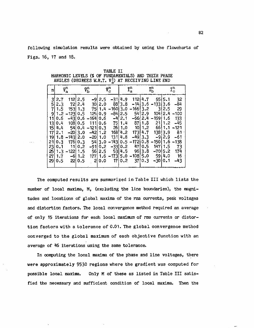
82
fo llo w in g sim u la tio n r e s u l t s were obtained by using th e flow charts o f
F ig s . 16, 17 and 18.
TABLE I IHARMONIC LEVELS (% OF FUNDAMENTALS) AND THEIR PHASE
ANGLES (DEGREES W.R.T. V*) AT RECEIVING LINE ENDci
n \ £ \ Vnc i:n•a TnLh I n
3 2.7 112 2.5 -9 2.5 -31 4.9 112 4.7 55 5.1 325 2 .3 72 2.4 30 2 .0 88 3 .8 -14 3 .6 -133 3 .6 -847 1.5 153 1.3 75 1.4 -160 3.0 -166 3.2 3 2.5 299 1.2 -123 0.5 125 0 .9 -84 2 .5 54 2.9 104 2 .4 -100
11 0.6 -43 0.6 -164 0.6 -4 2.1 -66 2.4 -159 1.6 13313 0 .4 108 0.5 111 0 .6 75 1.4 87 1.8 21 1.2 -4515 4.4 54 0.4 -121 0.3 26 1.0 10 1.2 66 1.1 -12117 2.1 -20 3 .0 -42 1.2 168 4 .2 173 4.7 138 3.9 8119 1.8 -143 2.0 -20 1.0 131 4 .8 -49 3.3 -9 2.9 -6121 0 .3 176 0 .3 54 3 .0 -143 0 .5 -172 0 .8 -150 1.6 -13823 0.1 11 0.2 -91 0 .2 -33 0.2 47 0.5 147 1.5 7325 1.3 -122 1.5 56 2.5 53 4 .5 96 3 .8 -70 5.2 17427 1.7 -6 1.2 177 1.6 -173 5 .0 -108 5.0 59 4.0 1629 0 .5 22 0.5 2 0 .0 17 0 .2 37 0 .3 -30 0.1 -43
The computed r e s u l t s a re summ arized in T a b le I I I which l i s t s th e
number o f lo c a l maxima, M, (excluding th e l in e boundaries), the magni
tudes and lo c a tio n s o f g lo b a l maxima o f th e rms c u rre n ts , peak v o ltag es
and d is to r t io n fa c to rs . The lo c a l convergence method requ ired an average
o f on ly 15 i te r a t io n s fo r each lo c a l maximum o f rms cu rren ts or d is to r
t i o n f a c t o r s w ith a t o l e r a n c e o f 0.01. The g lo b a l con v erg en ce method
co n v erg ed to th e g lo b a l maximum o f each o b je c t iv e fu n c tio n w ith an
average o f 46 i te r a t io n s u sing th e same to le ra n c e .
In computing th e lo c a l maxima o f th e phase and l in e v o lta g e s , th e re
w ere a p p ro x im a te ly 9530 re g io n s w here th e g r a d ie n t was computed f o r
p o ss ib le lo c a l maxima. Only M o f th e se as l i s t e d in Table I I I s a t i s
f ie d th e necessary and s u f f ic ie n t condition o f lo c a l maxima. Then the

83
s te e p e s t ascen t method u sing a fix ed s tep s iz e req u ired an average o f 17
i t e r a t io n s per lo c a l maximum w ith th e same to le ra n c e o f 0.01.
TABLE I I ICOMPUTED GLOBAL MAXIMA AND LOCATIONS OF RMS CURRENTS,
PEAK VOLTAGES AND DISTORTION FACTORS
RMS C urrent & Peak V oltage D is to rtio n F actor
M Mag. (pu) Loc.(mi) M Mag.(pu) Loc. (mi)
I 2 2.024 59.83 2 12.17 0.00i ; 3 2.020 63.64 2 11.80 0.00i bc 3 2.026 62.10 3 11.34 1.56
v . 17 1.89 114.02 2 21.11 118.35< 18 1.74 135.09 2 21.74 150.00
16 1.74 38.25 2 19.94 97.17
Vab 14 1.64 28.83 3 12.87 84.1212 1.55 88.38 3 8.99 35.47
r c a 13 1.78 146.72 3 12.36 137.36
To v e r i f y th e r e s u l t s o f T a b le I I I , th e t o t a l rms c u r r e n ts , peak
v o l ta g e s and d i s t o r t i o n f a c to r s were computed f o r a l l p o in ts o f th e
transm ission l in e w ith an increment o f .01 m ile . The r e s u l t s are shown
in F ig s . 20, 21 and 22, r e s p e c t i v e l y . The g lo b a l and l o c a l maxima as
w e ll as t h e i r lo c a tio n s co incide w ith those l i s t e d in Table I I I .
N ote t h a t n o t a l l th e l o c a l maxima o f th e peak v o l ta g e s can be
observed in Fig. 21. To see a l l th e lo c a l maxima in th e search region,
a th ree-d im ensional p lo t o f th e instan taneous v o lta g e s i s necessary as
shown in Fig. 23 fo r phase 'a 1 v o lta g e a t ± 1 /6 fQ seconds from th e tim e
when th e fundamental component reaches i t s maximum.
From th e r e s u l t s o f t h i s example, i t i s recognized th a t th e v a r ia
t io n between the minimum and maximum rms cu rren t i s no t ap p rec iab le . In
t h i s c a se th e v a r i a t i o n o f h e a t in g a lo n g th e l i n e s i s i n s i g n i f i c a n t .

84
For th e maximum peak v o l ta g e , how ever, th e d i f f e r e n c e betw een th e
maximum and minimum peak v a lu es could no t be ignored.
ooonCDCM
o
ooCM
3 ° -CL.
cc
25.00 50.00 75.00 100.00 125.00D I S T R N C E F R O M R E C E I V I N G E N D ( M I L E S )
50. 00
Fig. 20. V aria tio n o f RMS C urrents.
un
Q_
L U
X • - Q_'-'
Q_
25.00 50.00 75 .00D I S T R N C E F R O M R E C E I V I N G E N D ( M I L E S
1 0 0 . 0 0 125.00 50.00
(a)

85
oCD
Q_
>ab.
25 .00 D I S T R N C E F R O M
50.00F R O M
75.00 100.00R E C E I V I N G E N D ( M I L E S )
125.00 150.00
(b)
F ig . 21. V a r ia t io n o f Peak (a) Phase V o lta g e s and (b) L ine V o lta g e s .
aI D
C \J.
COainUjo_ac~ ocCJ
50 .0025 .00 50 .00 75.00 100.00 125.00D I S T R N C E F R O M R E C E I V I N G E N D ( M I L E S )
(a)

86
oocrj.
.C\1
O>
D OoCD 25.00 50.00
D I S T A N C E F R O M R E C E I V I N G E N D ( M I L E S )75.00
I V I N G100.00 125.00E N D ( M I L E S
150.00L
(b)
ooCO.
cat
a bo
u_Doo
50.0025.00 50.00 75.00D I S T A N C E F R O M R E C E I V I N G E N D ( M I L E S )
100.00 125.00( M I L E S )
0 . 0 0E N D
(c)
Fig. 22. D is to rtio n F acto r o f (a) C urrents, (b) Phase V oltagesand (c) Line V oltage.

87
Fig. 23. In stan taneous Phase a V oltage in Search Region.
77

6 . CONCLUSIONS
With th e ra p id ly in c reas in g a p p lic a tio n o f s t a t i c power co n v erte rs ,
harmonic l e v e l s in power and d is tr ib u tio n systems are becoming in to le r a
b le , thus lead in g to an in c reas in g number o f f a i lu r e s o f some components
and d e g ra d in g th e perfo rm ance o f some o th e r s . F u rth e rm o re , lo n g e r
te le p h o n e lo o p s and th e ra p id grow th o f d i g i t a l - d a t a tra n s m is s io n
dev ices may lead to in d u c tiv e communication in te rfe re n c e . Therefore, an
u rg e n t need o f n o v e l o r im proved m ethods has d e v e lo p e d f o r harm onic
a n a ly s is and m itig a tio n .
The m ajor c o n t r ib u t io n o f th e work p re s e n te d in t h i s d i s s e r t a t i o n
in c lu d es th e fo llow ing :
1. In c a se s where n o n l in e a r lo a d s a re random ly v a ry in g , a p r a c t i c a l
method h as been p re s e n te d f o r p r o b a b i l i s t i c m odeling o f harm onic
v o lta g e s and cu rre n ts . The r e s u l t in g p ro b a b ili ty c h a ra c te r is t ic s o f
the random s ig n a ls rep resen t a more r e a l i s t i c d e sc rip tio n o f h a r
monics in power systems. The p r in c ip a l a p p lic a tio n o f th e probabi
l i s t i c model i s fo r developing harmonic s tandards where p ro b a b ili ty
measures should be assigned to maximum p erm iss ib le l im its .
2 . C onsidering th a t the -e q u iv a le n t model o f a transm ission l in e on ly
p ro v id e s in fo rm a tio n a t th e l i n e te r m in a ls , e f f i c i e n t n u m erica l
m ethods a re p re s e n te d to compute and lo c a t e th e g lo b a l maximum o f
any s in g le v o lta g e o r cu rren t harmonic, o v e r a l l peak v o ltag e , t o t a l
rms c u rren t and d is to r t io n fa c to rs . Since th ese maxima may c re a te
h o t s p o ts , i n s u l a t i o n damage o r communication in te rfe re n c e , th e i r
p re d ic tio n i s im portant when harmonic l im ita tio n s a t th e transm is
sion l e v e l are to be observed.
88

89
Recommendations f o r f u tu r e r e s e a rc h e f f o r t s on power system h a r
monics in c lu d e
- Id e n tify in g inproved o r new methods fo r harmonic c o n tro l.
- Q u a n tita tiv e ly determ ining harmonic e f fe c ts on system components.
- Searching fo r inproved methods o f harmonic a n a ly s is .
- Relaxing some o f th e assumptions made fo r th e p ro b a b i l i s t ic harmonic
modeling.
- A ssessing harmonic e f f e c ts on power system dynamic s t a b i l i t y .
F in a l ly , i t i s th e au tho r’s opinion th a t s u f f ic ie n t coverage o f th e
harmonic problems should be given in a power e le c tro n ic s course.
f

REFERENCES
[1] C. R. C lin k e r, "Harmonic V oltages and C urrents in 'Wye' and 'D e lta ' Transform er Connections," AIEE T ra n s ., V ol. 33, 191^, pp. 723-33*
[2] R. P. S tra tfo rd , "Harmonic P o llu tio n in Power Systems - A Change in Philosophy," IEEE Trans. Ind. A ppl., V o l. 16, No. 5 , 1980, pp. 617-23.
[3] E le c t r ic Power Research I n s t i tu te (EPRI), D istr ib u tio n System Surge and Harmonic C h a ra c ter istic s , F in a l Report, Nov. 1980, EPRI EL- 1627, RP 1024-1, prepared by McGraw-Edison Co., United Technologies Corp. and Systems C ontro l Inc.
[4 ] J . A r r i l l a g a , D. A. B ra d ly and P. S. Bodger, Power Systems Harmonics, John Wiley & Sons, 1985.
[5] A. A. Mahmoud (Ed.), Power System Harmonics, IEEE T u to ria l Course, No. 84 EH0221-2-PWR, 1984.
[6] Y. Baghzouz and Owen T. Tan, "Harmonic A n a ly s is o f In d u c tio n Watthour Meter Performance," IEEE Trans. Power App. and S y st., Vol. PAS-102, No. 2 , 1985, pp. 399-406.
[7 ] W. F. H orton and S. G o ld b e rg , "The E f f e c t o f Harmonics on th e O perating P oin ts o f E lectrom echanical R elays," IEEE Trans. Power App. and S y st., V ol. PAS-104, No. 5, 1985, pp. 1178-88.
[8 ] A. M. S h a ra f , "Harmonic I n te r f e r e n c e from D is t r ib u t io n System s," IEEE Trans. Power App. and S y st., V o l. PAS-101, No. 8 , 1982, pp. 2975-81.
[ 9] IEEE Working Group on Power System Harmonics, "Power Line E ffec ts on Communication I n te r f e r e n c e ," IEEE Trans. Power App. and S y st., V o l. PAS-104, No. 9 , 1985, pp. 2578-87.
[10] M. F. McGranaghan, J . H. Shaw and R. E. Owen, "M easuring V o lta g e and C urrent Harmonics on D is tr ib u tio n Systems," IEEE Trans. Power App. and S y st., V o l. PAS-100, No. 7 , 1981, pp. 3599-608.
[11] G. D. B reu er, G. A ddis, R. H. L a s s a te r and J . J . V i th a y a t h i l , "HVDC-AC Harmonic In te ra c tio n , P a rt I I : AC System Model w ith Compariso n o f C a lcu la ted and Measured Data," IEEE Trans. Power App. and S y s t . , V o l. PAS-101, No.3, 1982, pp. 709-18.
[12] D. J . P i l e g g i , N. H. Chandra and A. E. Em anuel, " P re d ic t io n o f Harmonic V o lta g e s in Power S ystem s," IEEE Trans. Power App. and S y st., V ol. PAS-100, No. 3 , 1981, pp. 1307-15.
[13] A. A. Mahmoud and R. D. S h u l tz , "A Method f o r A n a ly z in g Harmonic D is trib u tio n in AC Systems," IEEE Trans. Power App. and S y st., Vol. PAS-101, No. 6 , 1982, pp. 1815-24.
90

91
[14] D. X ia and G. T. H eydt, "Harmonic Power Flow S tu d ie s , P a r t I : Form ulation and S o lu tio n , and P a rt I I : Im plem entation and P ra c t ic a l A p p lic a tio n ,” IEEE Trans. Power App. and S y st., V ol. PAS-101, No. 6 , 1982, pp. 1257-70.
[15] IEEE W orking Group on Power System H arm onics, "Power System H arm onics: An O v erv iew ," IEEE Trans. Power App. and S y st., V o l. PAS- 102, No. 8 , 1983, pp. 2455-60.
[16] A. E. Em anuel., J . A. O rr and D. C ygansk i, "The need o f C o l le c t io n o f A c tu a l D ata on V o lta g e and C u rre n t H arm onics," Proc. IEEE IAS Annual M eeting, Chicago* I l l i n o i s , S ep t. 30 - O ct. 4 , 1984, pp. 380- 6 .
[17] John A. O rr, A lex an d e r E. Emanuel and D avid G. P i l e g g i , "C u rren t Harmonics, V o ltage D is to rtio n and Powers A ssociated w ith E le c tr ic V e h ic le B a t te ry C h arg ers D is t r ib u te d on th e R e s id e n t ia l Power System ," IEEE Trans. Ind. Appl., V o l. IA -20, No. 4 , 1984, pp. 727- 734.
[18] R. DeVre, "Harmonic D is to r tio n Produced in Supply Networks by T e le v is io n R eceivers and L ight Dimmers," IEE Conf. Pub., No. 210, 1981,pp. 121-8.
[19] A. E. Emanuel and S. R. K a p r ie l ia n , " C o n tr ib u tio n to th e Theory o f S t o c h a s t i c a l l y P e r io d ic Harm onics in Power S ystem s," IEEE PES, Winter Meeting, New York, Feb. 2-7, 1986, Paper No. 86 WM 164-8.
[20] R. D. S h u l tz , R. A. Sm ith and G. L. H ickey , " C a lc u la t io n o f Maximum Harmonic C urrents and V oltages on Transm ission l in e s ," IEEE Trans. Power App. S y st., V o l. PAS-102, No. 4 , 1983, pp. 817-21.
[21] P. M. A nderson, A n a ly sis o f F aulted Power Systems, Iowa S ta te U n iv e rs ity P ress, Ames, Iowa, 1976.
[22] Y. Baghzouz and Owen T. Tan, "Harmonics in D is t r ib u t io n System s," Proc. 35th Annual Conf. fo r P r o te c t iv e Relay Engrs., Texas A&M U n iv ers ity , 1982, pp. 1-17.
[23] E. W. Kimbark, D irect Current Transm ission, John W iley and Sons, New York, 1971.
[24] IEEE Power System Harmonics Working Group, "B ibliography on Power System H arm onics, P a r t s I & I I , " IEEE Trans. Power App. and S yst., V o l. PAS-103, No. 9 , 1984, pp. 2460-79.
[25] P. P. B ir in g e r and M. A. S lon im , "D e te rm in a tio n o f H arm onics o f C onverter C urrent and/or V oltage Waveforms (New Method o f F ourier S e r ie s C o e f f i c i e n t s ) , P a r t s I & I I , " IEEE Trans. Ind. Appl., V o l. IA -16 , No. 2 , 1980, pp. 242-53 .

92
[26] J . W. C ooley and J . W. Tukey, "An A lg o rith m f o r th e M achine C a lc u la t io n o f Complex F o u rie r S e rie s ," Mathematics o f Computations, V ol. 19, A p ril 1965, pp. 297-301.
[27] IEEE Std 519-1981, Guide fo r Harmonic C ontrol and R eactive Compensation o f S ta tic Power Converters, IEEE P u b lica tio n , 1981.
[28] T. Subbarao and J . R eeve, "Harm onics Caused by Im balanced T ran sfo rm er Im pedances and Im p e rfe c t T w e lv e -P u ls e O p e ra tio n in HVDC C o n v e rs io n ," IEEE Trans. Power App. and S y st ., V o l. PAS-95 No. 5, 1976, pp. 1732-7.
[29] A. D. Graham and E. T. S ch o n h o lze r , "L ine Harm onics o f C o n v e r te rs w ith D.C. M otor L oads," IEEE Trans. Ind. Appl., V o l. IA -19, No. 1, 1983, pp. 84-93.
[30] R. L. Sm ith and R. P. S t r a t f o r d , "Power System Harmonics from A d ju s ta b le -S p e e d D r iv e s ," IEEE Trans. Ind. Appl., V o l. IA -29, No. 4 , 1984, pp. 973-77.
[31] J . A. O rr, A. E. Emanuel and D. J . P i l e g g i , "C u rren t H arm onics, V oltage D is to rtio n , and Powers A sso c ia te d w ith B a t te ry C h arg ers , P art I : Comparisons Among D iffe ren t Types o f Chargers," IEEE Trans. Power App. and S y st., V o l. PAS-101, No. 8 , 1982, pp. 2703-10.
[32] A. K. W a lla c e , E. S. Ward and A. W righ t, "S ources o f Harmonic C u rre n ts in S lip -R in g In d u c tio n M otors ," Proc. IEE, V o l. 121, No. 12, 1974, pp. 1495-1500.
[33] T. J . E. M i l l e r , R eactive Power Control in E le c tr ic Systems, John Wiley & Sons, 1982.
[34] G. Goldberg, "Behavior o f Apparatus under th e In flu en ce o f V oltage and C u rre n t H arm onics," B u ll . Soc. R. B eige E le e tr ., V o l. 91, No. 4, 1975, pp. 225-35.
[35] W. S. Wood, F. P. F ly n n and A. P oray , " E f f e c ts o f Supp ly V o lta g e Waveform D is to r t io n on M otor P erfo rm an ce ," In t. Conf. on Sources and E ffe c ts o f Power System D isturbances, London , England, A p ril 1974, pp. 261-7.
[ 36] E le c tr ic Power Research I n s t i tu te (EPRI), Evaluation o f E lectr ica l In terferen ce to th e Induction Watthour Meter, EL-2315, R esearch P ro jec t No. 1738, F in a l Report, A p ril 1982.
[37] IEEE Power System R elaying Committee, Sine-Wave Distortion in Power Systems and the Impact on Protective Relaying, F in a l Report, 84 TH 0115-6 PWR, 1984.
[38] W. Shepherd and P. Zand, Energy Flow and Power Factor in Non- s in u so id a l C irc u its , Cambridge U n iv e rs ity P ress , England, 1979.

93
[39] H. S a sak i and T. M achida, "A new Method to E l im in a te AC Harmonics by M agnetic F lu x C om pensation ,” IEEE T ran s . Power App. and S y s t., V o l. PAS-100, No. 11, 1971, pp. 2009-19.
[40] A. Aminati, "G eneralized Method o f Harmonic Reduction in AC/DC conv e r te r s by Harmonic C urrent In je c tio n ,” P roc . IEE, Vol. 119, No. 7,1972, pp. 857-64.
[41] H. S. P a te l and R. G. H o ft, " G e n e ra liz e d T echniques o f Harmonic E lim ination and V oltage C ontrol in T h y ris to r In v e r te rs : P a rt I - Harmonic E l im in a t io n ," IEEE T ran s . In d . A pp l., V o l. IA -10, No. 3,1973, pp. 310-17.
[42] J . F. B a ird an J . A r r i l l a g a , "Harmonic R eduction in D. C. R ip p le R ein jec tio n ," P r o c . IE E , V o l. 127, P t. C, No. 3, 1980, pp. 294-303.
[431 M. F. McGranaghan R. C. Dugan, J . A. King and W. T. J e w e l l , "D is trib u tio n Feeder Harmonic Study Methodology," IEEE T ran s . Power App. and S y s t . , V o l. PAS-103, No. 12, 1984, pp. 3663-71.
[44] E l e c t r i c Power R esearch I n s t i t u t e (EPRI), Harmonic Power Flow S tu d ie s , V o l. 1: T h e o r e t ic a l B a s is , EL-3300, P r o je c t No. 1764-7, Prepared by Purdue U n iv e rs ity , F in a l Report, November, 1983.
[45] W. M. Grady and G. T. H eydt, " P re d ic t io n o f Power System Harmonics Due to G aseous D isch a rg e L ig h tin g ," IEEE PES Summer M eeting , S e a tt le , Washington, Ju ly 15-20, 1984, paper No. 84 SM 555-9.
[46] G. L. K usic and I . A. Whyte, "T hree-P hase S tead y S ta te S t a t i c VAR Generator F i l t e r Design fo r Power Systems," IEEE T ran s . Power App. and S y s t. , V o l. PAS-103, No. 4 ., 1984, pp. 811-18.
[47] B. Szabados and J. Lee, "Harmonic Impedance Measurements on Transform ers," IEEE T ra n s . Power App. and S y s t . , V o l. PAS-100, No. 12, 1981, pp. 5020-26.
[48] Owen T. Tan and P. H i l l e r s , Power System Harmonic A n a ly s is , Technic a l R eport p re p a re d f o r L o u is ia n a Power and L ig h t Co., L o u is ia n a S ta te U n iv ers ity , Baton Rouge, Louisiana, September, 1981.
[49] R. H. K itc h in , "New Method o f D ig i t a l Computer E v a lu a t io n o f Conv e r te r Harmonics in Power Systems Using S ta te -V a ria b le A nalysis ," P r o c . IE E , V o l. 128, P t . C, No. 4 , 1981, pp. 196-206.
[50] B. T. C oi, N. M enem enlis and H. L. N akra, " F a s t S te a d y -S ta te S o lu t i o n f o r HVDC A n a ly s is ," IEEE T ran s . Power App. and S y s t . , V o l. PAS-99, No. 6, 1980, pp. 2453-59.
[51] S. W illia m s and I . R. Sm ith , "F a s t D i g i t a l C om putation o f T h ree - Phase T h y ris to r Bridge C irc u its ," P roc . IEE, Vol. 120, No. 7, 1973, pp. 791-95.

94
[52] G. S tag g and A. E l-A b iad , Computer M ethods in Power System A nalys i s , McGraw-Hill Book Co., New York, 1968.
[53] M. F. McGranaghan, R. C. Dugan and W. L. S ponsler, "D ig ita l Simulat io n o f D is tr ib u tio n System F requency R esponse C h a r a c t e r i s t i c s , " IEEE T ran s . Power App. and S y s t . , V o l. PAS-100, No. 3 , 1981, pp. 1362-9.
[54] W. G. Sherman, "Summation o f Harm onics w ith Random Phase A n g les ," IEE P ro c ., V o l. 119, No. 11, 1972, pp. 1643-8.
[55] N. B. Rowe, "The Summation of Randomly Varying Phasors or V ectors w ith P a r t ic u la r Reference to Harmonic L ev e ls ," IEE Conf. Pub., No.210, 1981, pp. 121-8.
[56] A. K loss, " S ta t i s t i c a l A nalysis o f Harmonic Problems in Power E lec tro n ic I n s ta l la t io n s ," B u l l . A ssoc. S u is e s E l e c t r . , V ol. 66, No. 8, 1975, pp. 427-33.
[57] Y. Baghzouz and Owen T. Tan, " P r o b a b i l i ty D is t r ib u t io n o f th e Summation o f Random Power System H arm onics," P ro c . IEEE SOUTH- EASTCON., R aleigh , NC, March 31 - A p ril 3, 1985, pp. 39-44.
[58] R. E. M orrison and A. D. C la rk , " P r o b a b i l i s t i c R e p re se n ta tio n o f Harmonic C urrents in AC T raction Systems," P roc. IEE, Vol. 131, No. 5 , 1984, pp. 181-9.
[59] Y. Baghzouz and Owen T. Tan, " P r o b a b i l i s t i c M odeling o f Power System Harmonics," IEEE I&CP T echnical Conference, C leveland , Ohio, May 5-8 , 1986. (Also considered fo r p u b lic a tio n in IEEE Trans, on In d u stry A p p lica tio n s)
[60] J . A. O rr, D. C ygansk i, A. E. Emanuel and R. T. S a le h , "Design o f a System f o r Autom ated M easurem ent and S t a t i s t i c s C a lc u la t io n o f V oltage and C urrent Harmonics," IEEE PES, W in te r M eeting , New York, Feb. 2 -7 , 1986, P aper No. 86 Wm 198-6.
[61] Paul G. Hoel, Sidney C. Port and C harles J . Stone, In t r o d u c t io n t o P r o b a b i l i t y T heory , Houghton M iffin Co., 1971
[62] H. J . Nussbaumer, F a s t F o u r ie r T ransfo rm and C o n v o lu tio n A lgor i th m s , H eidelberg , Germany, Springer V erlag , 1982.
[63] R. Agarw al and J . W. C ooly , "New A lg o rith m s f o r D ig i t a l C onvolut io n ," IEEE T ran s , on ASSP, V o l. 25, No. 5 , 1977, pp. 392-410.
[64] P. M. Anderson and A. Bose, "A P r o b a b i l i s t i c Approach to Power System S ta b i l i t y A n alysis ," IEEE T ran s . Power App. and S y s t . , Vol. PAS-102, No. 8 , 1983, pp. 2430-39.

95
[65] R. N. A l la n and A. M. L e i te da S i l v a , " P r o b a b i l i s t i c Load Flow U sing M u l t i - L in e a r iz a t io n ," P ro c . IE E , V o l. 128, P t. C, No. 5,1981, pp. 280-87.
[66] J . G r if f in , "F luorescen t Lamps, N eu tra l C urrents and Standby Gener a to r s ," E l e c t r i c a l Review , V ol. 204, Jan. 1979, pp. 21-2.
[67] T. L. B aitch , "The A u s tra lian Standard to Specify Network Harmonic L im its : AS 2279-1979," IEEE T ran s . In d . A p p l., V o l. IA -18 , No.3,1982, pp .260-7 .
[68] The E l e c t r i c i t y C o u n c il, L im its f o r Harm onics in t h e U n ited Kingdom E le c t r i c i ty jS u p p ly System , Recommendation G5/3, London, S ep t. 1976.
[69] Y. Baghzouz and Owen. T. Tan, "Computation o f Maximum RMS Current and Peak V o lta g e on T ran sm iss io n L in es under N o n sin u so id a l Cond itio n s ," IEEE PES W in te r M eeting , New York, Feb. 2-7, 1986, Pa£er No. 86 WM 153-1.
[70] J . A r r i l l a g a , T. J . Densem and B. J . H arker, "Zero Sequence H armonic C urrent G eneration in Transm ission Lines Connected to a Large C o n v e r te r P l a n t , " IEEE T ran s . Power App. and S y s t . , V o l. PAS-102, No. 7 , 1983, pp. 2357-63.
[71] T. J . Densem, P. S. Bodger and J . A r r i l l a g a , "Three Phase T ran sm iss io n System M odeling f o r Harmonic P e n e tr a t io n S tu d ie s ," IEEE T ran s . Power App. S y s t . , V o l. PAS-103, No. 2 , 1984, pp. 310-17.
[72] Y. Baghzouz and Owen T. Tan, "Maximum H ea tin g and I n s u l a t i o n S tre ss on Untransposed Transm ission Lines w ith Unbalanced Harmonic D is to r t io n ," IEEE PES Summer M eeting , J u ly 20-25 , 1986, Mexico C ity, Mexico, paper No. GS 10 SPM-86.
[73] Bruno 0. Shubert, "A S eq u en tia l Method Seeking th e G lobal Maximum o f a Function," SIAM J o u r n a l o f N um erical A n a ly s is , V ol. 9, No. 3, S ep t. 1972, pp. 379-88.
[74] M. Chen and W. E. D illo n , "Power System M odeling," P roc . IEEE, Vol. 62, No. 7 , 1974, pp. 901-15.
I[75] W. I . Bowman and J. M. McNamee, "Development o f E qu ivalen t P i and T
M atrix C i r c u i t s f o r Long U n transposed T ran sm iss io n L in e s ," IEEE T ran s . Power App. S y s t . , V o l. PAS-84, No. 6 , 1964, pp. 625-32.
[76] S. S. Rao, O p tim iz a tio n Theory and A p p l ic a t io n s , W iley E a s te rn Lim ited, 1984.

APPENDIX I
HARMONIC COMPUTATION OF DISTORTED WAVEFORMS
The F o u r ie r s e r i e s o f a p e r io d ic fu n c t io n w (t) w ith p e r io d T i s
given by00
w (t) = WQ + Z {ancos (norfc) + b s in (n o ) t) } (A.1)n=l
where
W = i f w (t) d t. - i f -0 T Jo
2 f T ■ J J 0 »
b = -n T
(t) cos (nuit) d t
Tw (t) sin(nuit) d t
o
and a) = 2rr/T. Equation (A.1) may be re w ritte n in th e fo llo w in g form:
00
w (t) = W + Z {W cos(no)t + c> } (A.2)o . n rnn=lwhere ,- /-2. , *5
and
W - (a + b z) n n n
<()n = a rc tan (b n/ a n) .
In g en e ra l, v o lta g e and c u rren t waveforms found in power systems are
ro ta t io n a l symmetric. Then, (A.2) reduces to
00
w (t) = Z Wnoos(n u t + (j>n) . (A.3)n - 1 /
The cu rre n t and v o lta g e waveforms found in co n v erte r i n s t a l l a t io n s
a re g e n e ra lly d iscon tinuous s e v e ra l tim es per period due SCR sw itchings.
The r e p e t i t i v e i n t e g r a t i o n s f o r each i n t e r v a l w here th e v o l ta g e o r
cu rren t i s continuous may then be avoided by using th e complex form o f
F o u r ie r s e r i e s . In such c a s e s , th e F o u r ie r c o e f f i c i e n t s a re g e n e r a l ly
96
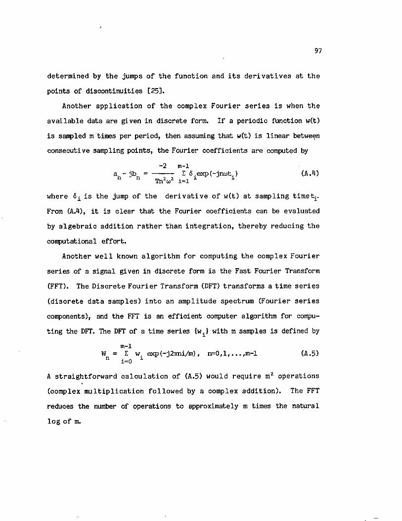
97
d e te rm in ed by th e jumps o f th e fu n c tio n and i t s d e r i v a t i v e s a t th e
p o in ts o f d is c o n t in u itie s [25].
A nother a p p l i c a t io n o f th e com plex F o u r ie r s e r i e s i s when th e
a v a i la b le data a re g iven in d is c re te form. I f a p e rio d ic function w(t)
i s sampled m tim es per p e rio d , then assuming th a t w(t) i s l in e a r between
consecu tive sam pling p o in ts , th e F ourier c o e f f ic ie n ts a re computed by
- 2 m-1a - jb = --------- E 6 .ex p (-jn u rt.) (A.M)n n _ 2 2 ■ i i iTnzar x=l
w here 6. i s th e jump o f th e d e r i v a t i v e o f w (t) a t sam p lin g t im e t±.
From (A.4), i t i s c le a r th a t th e F o u rie r c o e f f ic ie n ts can be ev a lu a ted
by a lg e b r a ic a d d i t io n r a t h e r th a n i n t e g r a t i o n , th e re b y re d u c in g th e
com putational e f fo r t .
A nother w e l l known a lg o r i th m f o r com puting th e com plex F o u r ie r
s e r ie s o f a s ig n a l given in d is c re te form i s th e F as t F o u rie r Transform
(FFT). The D is c r e te F o u r ie r T ransform (DFT) tra n s fo rm s a tim e s e r i e s
( d i s c r e t e d a ta sam p les) i n to an a m p litu d e spectrum (F o u rie r s e r i e s
components), and th e FFT i s an e f f ic ie n t computer a lg o rith m fo r compu
t in g th e DFT. The DFT o f a tim e s e r ie s (wi > w ith m samples i s defined by
m -lW = E w. exp(-j2Tm i/m ), n = 0 , l , . . . ,m -l (A.5)
n i=0 1
A s t r a ig h t f o r w a r d c a l c u l a t i o n o f (A.5) would r e q u i r e m2 o p e ra t io n s
(com plex m u l t i p l i c a t i o n fo llo w e d by a com plex a d d i t io n ) . The FFT
reduces the number o f opera tio n s to approxim ately m tim es th e n a tu ra l
lo g o f m.

APPENDIX I I
EQUIVALENT SERIES IMPEDANCE AND SHUNT ADMITTANCE OF TRANSMISSION LINES
In a th ree-phase transm ission l in e w ith a t o t a l o f x bundled con
d u c to rs and y ground w ire s , th e v o l ta g e e q u a tio n f o r any harm onic
frequency n i s given by [21]
where
1* n
v 2n
v 31n
1!
0
0
211 Z12
?n 7n J21 22 • •
zn1,x+y
zn2,x+y
x+y ,x+y.
r ? ii n- 2I n
- XI n
•
•
jx+yn
-n ,n . „nZ“± = (RV + R“) + j (2 .02233x10"3) f Qn ln (D “/D ±) Q/mi
(A .6)
z j j = R* + j (2 .02233x10” 3) f Qn l n ^ / D . . . . ) fi/mi
w ith
R° a Rn = - i —-
ber a b e i 1 a - b e i a b e r ' a n n n n
(b e r 1 a ) + (b e i' a ) ‘n n
R*j = *-(1.588x10” 3) f Qn fi/m i
(A.7)
i f= (2 i6 0 > /p 7 ir ) /v f i f t
a = ( . 0 6 3 6 /R?) .o' 1
H erein,
u>0, f : Angular and l in e a r fundamental frequencies
98

99
D.xD. .
R°X
: Earth re s is ta n c e a t n - th harmonic frequency
: GMR o f conductor i
: D istance between conductors i and j
: Dc re s is ta n c e o f conductor i
b e r ,b e r ': Real B essel function and i t s d e riv a tiv e
b e i ,b e i ': Imaginary B essel func tion and i t s d e riv a tiv e
p : Earth r e s i s t i v i t y (=100 fo r damp e a rth )
Z*j\ : S e l f impedance o f conductor i (i= j) and mutual im
pedance between conductors i and j ( i / j )
Equation (A.6) can be reduced to th e p a r ti t io n e d form
[V11] [zj] [z£][ 0 ] [Z“ ] t z ?
[ in ]
[I ](A.8)
E lim inating [I ] from (A.8) r e s u l t s in
[V11] = [Zn] [ In] , [Zn] = [z“] - [z“] [z"]"1 ^ " ].2 1 4J (A.9)
For th e shunt adm ittance m atrix fo rm ulation , th e p o te n t ia ls o f the
l in e conductors are r e la te d to th e conductor charges by
where
[V11] = [ P ] [ q n]
[v11] = [V V11 0 0 . . . 0]
[ ? ] = [q j ^ ^ +y]
P .. = (l/2ire) ln ( H . / r .)XX X X
(A .10)
H erein,
p±j = (l/2ire) In (H ^ /lX ..) , i ^ j .
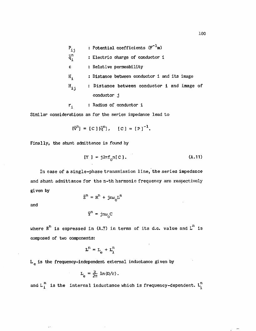
100
Pi; . : P o te n tia l c o e f f ic ie n ts (F-1m)
q” : E le c tr ic charge o f conductor i
e : R ela tiv e perm eab ility
H± : D istance between conductor i and i t s image
Hi;. : D is ta n c e betw een co n d u cto r i and image o f
conductor j
r ± : Radius o f conductor i
S im ila r co n sid era tio n s as fo r th e s e r ie s impedance lead to
[V 11] = t C ] [ q n ] , [ C ] = [ P ] " 1 .
F in a l ly , th e shunt adm ittance i s found by
[Y ] = j2 irfon[C ] . (A.11)
In case o f a s in g le - p h a s e t ra n s m is s io n l i n e , th e s e r i e s im pedance
and sh u n t a d m itta n ce f o r th e n - th harm onic freq u en cy a re re sp e c tiv e ly
given byZn = Rn + j n w L n o
and
Y 11 = jn u )QC
w here Rn i s e x p re ssed in (A.7) in te rm s o f i t s d .c . v a lu e and L11 i s
composed o f two components:
L n = L + L ne x
L g i s th e frequency-independent e x te rn a l inductance given by
L e = ^ m (D / r ) .
and L ? i s th e i n t e r n a l in d u c ta n c e which i s f req u e n cy -d ep e n d e n t.

101
i s r e la te d to i t s d.c. v a lu e by
n 4 L °L % - 1 1 an
ber a ber1 a + b ei a b e i1 a n n n n
(ber1 a ) + (b e i1 a )n n
(A.12)
VITA
Yahia Baghzouz was born on August 13, 1956, in Beni-Amrane, A lgeria .
He a t te n d e d e le m e n ta ry and seco n d ary s c h o o ls in A lg ie r s , A lg e r ia ,
g ra d u a tin g from LTGA (Lycee T echnique de G arcons d’A lg e r) h ig h sc h o o l
w ith honors in May, 1976. In August o f 1977, he en tered Louisiana S ta te
U n iv e rs ity in Baton Rouge, Louisiana, USA, and rece iv ed h is Bachelor and
M aste r o f S c ien ce d e g re e s in E l e c t r i c a l E n g in ee rin g in May 1981 and
December 1982, re s p e c tiv e ly . He has h e ld a resea rch a s s is ta n tsh ip from
June 1981 to J u ly 1985. From A ugust 1985 to th e p r e s e n t , he h o ld s an
i n s t r u c t o r p o s i t io n in th e E l e c t r i c a l and Computer E n g in ee rin g
Department. He i s a member o f E ta Kappa Nu honor so c ie ty and a s tuden t
member o f IEEE. P r e s e n t ly , he i s a c a n d id a te f o r th e deg ree o f D octor
o f Philosophy in E le c t r ic a l Engineering.
102

DOCTORAL EXAMINATION AND DISSERTATION REPORT
Candidate: Yahia Baghzouz
Major Field: E l e c t r i c a l Engineering
Title of Dissertation: Contribution to Power System Harmonic Analys is
Approved:
Major Professor and Chairman
Dean o f the Graduate Schtfol
EXAMINING COMMITTEE:
Date of Examination:
A pril 24. 1986


![[X]Fundamental Principles to Power System Harmonic](https://img.pdfslide.net/doc/110x75/577c7caa1a28abe0549b8655/xfundamental-principles-to-power-system-harmonic.jpg)