Embed Size (px)
Citation preview

MFS268_6217_ANL_EN.doc 01/06
REO ELEKTRONIK AG Brühler Strasse 100 D-42657 Solingen Tel. 0049-(0)212-88 04-0 Fax 0049-(0)212-88 04-188 www.reo.de eMail: [email protected]
Operating Instructions
REOVIB MFS 268 400 V, 8/16 A 230 V, 32 A Frequency Converter for Vibratory Feeders
ELEKTRONIK
Con
trol E
quip
men
t for
the
Vib
rato
ry F
eede
r Ind
ustry

Operating Instructions REOVIB MFS 268
1
ELEKTRONIK
Technical safety instructions for the user This description contains the necessary information for the correct application of the product described below. It is intended for use by technically qualified personal. Qualified personnel are persons who, because of their training, experience and position as well as their knowledge of appropriate standards, regulations, health and safety requirements and working conditions, are authorised to be responsible for the safety of the equipment, at all times, whilst carrying out their nor-mal duties and are therefore aware of, and can report, possible hazards (Definition of qualified employees according to IEC 364) Safety Instructions The following instructions are provided for the personal safety of operators and also for the protection of the described product and connected equipment.
Warning! Hazardous Voltage Failure to observe can kill, cause serious injury or damage
• Isolate from mains before installation or dismantling work, as well as for fuse changes or post installa-
tion modifications. • Observe the prescribed accident prevention and safety rules for the specific application. • Before putting into operation check if the rated voltage for the unit conforms with the local supply
voltage. • Emergency stop devices must be provided for all applications. Operation of the emergency stop must
inhibit any further uncontrolled operation. • The electrical connecting terminals must be covered! • Earth bonding must be tested for integrity after installation. Specified Use The units described herein are electrical controllers for installation in industrial plant. They are designed for controlling vibratory feeders.
!
Operating Instructions REOVIB MFS 268
2
ELEKTRONIK
Contents
Technical safety instructions for the user......................................................................................................1 Contents........................................................................................................................................................2 1.0 General ...................................................................................................................................................3 2.0 Function ..................................................................................................................................................4
2.1 Track control........................................................................................................................................4 2.2 Operating with two speeds (2 set points for coarse/fine switching) ....................................................4
2.2.1 Time delayed change-over to 2nd setpoint..........................................................................................4 2.3 Control inputs and output ....................................................................................................................5 2.3.1 Enable input......................................................................................................................................5 2.3.2 Sensor input for track control ...........................................................................................................5 2.3.3 External set point..............................................................................................................................5 2.3.4 Output status relay ...........................................................................................................................5
2.3.5 Ready relay ..........................................................................................................................................5 2.4 Display.................................................................................................................................................5
3.0 Construction ............................................................................................................................................6 3.1 Enclosed units .....................................................................................................................................6 3.2 Panel mounting units ...........................................................................................................................6
4.0 Technical Data ........................................................................................................................................7 6.0 Declaration of Conformity .......................................................................................................................7 7.0 Settings ...................................................................................................................................................8 8.0 Control elements .....................................................................................................................................9
8.1 Settings................................................................................................................................................9 9.0 Commissioning......................................................................................................................................10
9.1 Assembling position...........................................................................................................................10 9.2 Preliminary steps...............................................................................................................................10 9.2.1 Important points..............................................................................................................................10 9.2.1.1 Operating frequency of the feeder coil ........................................................................................10 9.2.1.2 Measurement of the output voltage and current .........................................................................10 9.3 Putting the equipment into operation.................................................................................................11
10.0 Setting Instructions..............................................................................................................................12 10.1 User adjustment of throughput ........................................................................................................12 10.2 Tuning the feed system ...................................................................................................................12 10.2.1 Feeder settings.............................................................................................................................12 10.2.2 Track control.................................................................................................................................13 10.2.3 Sensor time out ............................................................................................................................13 10.2.4 Set point source............................................................................................................................14 10.2.5 Pulse feed.....................................................................................................................................14 10.2.6 Regulation mode ..........................................................................................................................15 10.2.6.1 Instructions for using regulation mode ......................................................................................15 10.2.6.2 Mounting the accelerometer......................................................................................................16 10.2.6.3 Relationship between acceleration and amplitude....................................................................17 10.2.6.4 Instructions for setting up the controller in regulation mode .....................................................17 10.2.6.5 Determining the resonant frequency .........................................................................................18 10.2.6.6 Optimisating controller in regulation mode................................................................................18 10.2.6.7 Displays .....................................................................................................................................19 10.2.7 Display actual current and frequency...........................................................................................20 10.2.8 Save selected parameters............................................................................................................20 10.2.9 Recall user or factory settings ......................................................................................................20 10.2.10 Hide parameter menus...............................................................................................................20
11.0 Error messages / ERROR reset..........................................................................................................21 12.0 Connection diagrams ..........................................................................................................................22
12.1 Connections for 16/32A versions ....................................................................................................22 12.2 Connections for 16/32A versions ....................................................................................................23
13.0 Dimensions .........................................................................................................................................24 13.1 Dimensions of 16/32 A Unit.............................................................................................................24 13.2 Dimensions of 8 A Unit ....................................................................................................................25
A 1.0 Service appendix ...............................................................................................................................26
Operating Instructions REOVIB MFS 268
3
ELEKTRONIK
31 32 3321 22 23 26 27 28
123456
+24V
+24V
+24V
51 52 53 54 55 56 57 58
L1 L2 L3 PE PE
PE A1 A2
REOVIB MFS 268
1 2 3 4 5 6 31 32 3321 22 23 26 27 28
51 52 53 54 55 56 57 58
+10V
7 8 910
7 8 9 10
I
0P
F
ELEKTRONIK
P P PSPEED
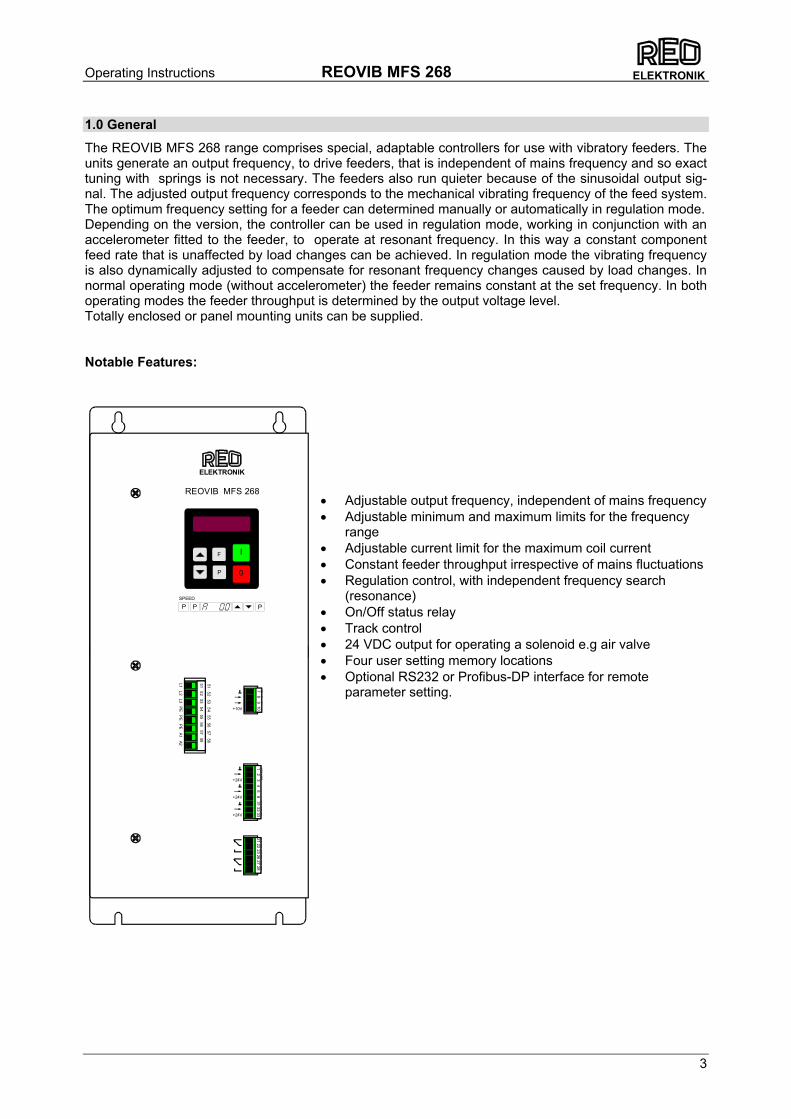
1.0 General
The REOVIB MFS 268 range comprises special, adaptable controllers for use with vibratory feeders. The units generate an output frequency, to drive feeders, that is independent of mains frequency and so exact tuning with springs is not necessary. The feeders also run quieter because of the sinusoidal output sig-nal. The adjusted output frequency corresponds to the mechanical vibrating frequency of the feed system. The optimum frequency setting for a feeder can determined manually or automatically in regulation mode. Depending on the version, the controller can be used in regulation mode, working in conjunction with an accelerometer fitted to the feeder, to operate at resonant frequency. In this way a constant component feed rate that is unaffected by load changes can be achieved. In regulation mode the vibrating frequency is also dynamically adjusted to compensate for resonant frequency changes caused by load changes. In normal operating mode (without accelerometer) the feeder remains constant at the set frequency. In both operating modes the feeder throughput is determined by the output voltage level. Totally enclosed or panel mounting units can be supplied. Notable Features:
• Adjustable output frequency, independent of mains frequency • Adjustable minimum and maximum limits for the frequency
range • Adjustable current limit for the maximum coil current • Constant feeder throughput irrespective of mains fluctuations • Regulation control, with independent frequency search
(resonance) • On/Off status relay • Track control • 24 VDC output for operating a solenoid e.g air valve • Four user setting memory locations • Optional RS232 or Profibus-DP interface for remote
parameter setting.
Operating Instructions REOVIB MFS 268
4
ELEKTRONIK
t ON t OFF
Sensor
Feeder ON
OFF
ON
OFF
Soft Start Soft Stop
2.0 Function
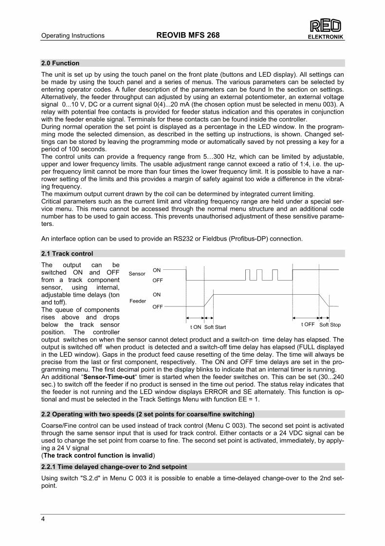
The unit is set up by using the touch panel on the front plate (buttons and LED display). All settings can be made by using the touch panel and a series of menus. The various parameters can be selected by entering operator codes. A fuller description of the parameters can be found In the section on settings. Alternatively, the feeder throughput can adjusted by using an external potentiometer, an external voltage signal 0...10 V, DC or a current signal 0(4)...20 mA (the chosen option must be selected in menu 003). A relay with potential free contacts is provided for feeder status indication and this operates in conjunction with the feeder enable signal. Terminals for these contacts can be found inside the controller. During normal operation the set point is displayed as a percentage in the LED window. In the program-ming mode the selected dimension, as described in the setting up instructions, is shown. Changed set-tings can be stored by leaving the programming mode or automatically saved by not pressing a key for a period of 100 seconds. The control units can provide a frequency range from 5…300 Hz, which can be limited by adjustable, upper and lower frequency limits. The usable adjustment range cannot exceed a ratio of 1:4, i.e. the up-per frequency limit cannot be more than four times the lower frequency limit. It is possible to have a nar-rower setting of the limits and this provides a margin of safety against too wide a difference in the vibrat-ing frequency. The maximum output current drawn by the coil can be determined by integrated current limiting. Critical parameters such as the current limit and vibrating frequency range are held under a special ser-vice menu. This menu cannot be accessed through the normal menu structure and an additional code number has to be used to gain access. This prevents unauthorised adjustment of these sensitive parame-ters. An interface option can be used to provide an RS232 or Fieldbus (Profibus-DP) connection. 2.1 Track control
The output can be switched ON and OFF from a track component sensor, using internal, adjustable time delays (ton and toff). The queue of components rises above and drops below the track sensor position. The controller output switches on when the sensor cannot detect product and a switch-on time delay has elapsed. The output is switched off when product is detected and a switch-off time delay has elapsed (FULL displayed in the LED window). Gaps in the product feed cause resetting of the time delay. The time will always be precise from the last or first component, respectively. The ON and OFF time delays are set in the pro-gramming menu. The first decimal point in the display blinks to indicate that an internal timer is running. An additional “Sensor-Time-out“ timer is started when the feeder switches on. This can be set (30...240 sec.) to switch off the feeder if no product is sensed in the time out period. The status relay indicates that the feeder is not running and the LED window displays ERROR and SE alternately. This function is op-tional and must be selected in the Track Settings Menu with function EE = 1. 2.2 Operating with two speeds (2 set points for coarse/fine switching)
Coarse/Fine control can be used instead of track control (Menu C 003). The second set point is activated through the same sensor input that is used for track control. Either contacts or a 24 VDC signal can be used to change the set point from coarse to fine. The second set point is activated, immediately, by apply-ing a 24 V signal (The track control function is invalid)
2.2.1 Time delayed change-over to 2nd setpoint
Using switch "S.2.d" in Menu C 003 it is possible to enable a time-delayed change-over to the 2nd set-point.
Operating Instructions REOVIB MFS 268
5
ELEKTRONIK
2.3 Control inputs and output
2.3.1 Enable input
External switch or 24 VDC signal voltage. External control function to switch the power output ON or OFF e.g. Networking of several controllers from a central PLC. 2.3.2 Sensor input for track control
Sensor for monitoring the queue of components on the track or an input for switching to the second set point 24 VDC (PNP). 2.3.3 External set point
The feeder amplitude set point can be provided from and external, analog 0...10 V, DC, 0(4)...20 mA, or a 10 kR Potentiometer. Parameter ESP in Menu C003 must be set to 1, for an external set point source to be used (not on 16A units). Setting the minimum output value when external set point = 0:- Before changing the ESP parameter to accept an external set point source, the minimum value can be adjusted by using the cursor keys, on the front panel, and this will remain when the ESP is changed over from 0 to 1. 2.3.4 Output status relay
Status-Relay contact 250 V/1 A (changeover). Relay closes when the feeder is running – the relay opens when there is no enable signal or a fault displayed.
2.3.5 Ready relay
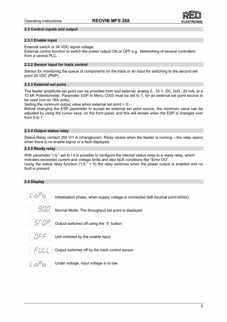
With parameter “r.b.“ set to I it is possible to configure the internal status relay to a ready relay, which indicates exceeded current and voltage limits and also fault conditions like “Error OU”. Using the status relay function (“r.b.” = 0) the relay switches when the power output is enabled and no fault is present. 2.4 Display
Initialisation phase, when supply voltage is connected (left decimal point blinks).
Normal Mode: The throughput set point is displayed
Output switched off using the `0` button Unit inhibited by the enable input Output switched off by the track control sensor Under voltage, input voltage is to low.
Operating Instructions REOVIB MFS 268
6
ELEKTRONIK
3.0 Construction
The units are available as stand-alone, enclosed or panel mounting versions . 3.1 Enclosed units
• Mains switch • Touch panel with display • Mains cable with plug • Output cable or output socket for connecting to the feed system • Sensor socket. The standard unit has provision for 24 VDC sensors with a PNP output 3.2 Panel mounting units
• Touch panel with display
• Terminals for electrical connections
• Screw hole fixings for mounting
Operating Instructions REOVIB MFS 268
7
ELEKTRONIK
4.0 Technical Data
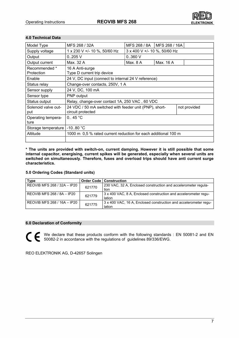
Model Type MFS 268 / 32A MFS 268 / 8A MFS 268 / 16A Supply voltage 1 x 230 V +/- 10 %, 50/60 Hz 3 x 400 V +/- 10 %, 50/60 Hz Output 0..205 V 0..360 V Output current Max. 32 A Max. 8 A Max. 16 A Recommended * Protection
16 A Anti-surge Type D current trip device
Enable 24 V, DC input (connect to internal 24 V reference) Status relay Change-over contacts, 250V, 1 A Sensor supply 24 V, DC, 100 mA Sensor type PNP output Status output Relay, change-over contact 1A, 250 VAC , 60 VDC Solenoid valve out-put
24 VDC / 50 mA switched with feeder unit (PNP), short-circuit protected
not provided
Operating tempera-ture
0.. 45 °C
Storage temperature -10..80 °C Altitude 1000 m 0,5 % rated current reduction for each additional 100 m
* The units are provided with switch-on, current damping. However it is still possible that some internal capacitor, energising, current spikes will be generated, especially when several units are switched on simultaneously. Therefore, fuses and overload trips should have anti current surge characteristics. 5.0 Ordering Codes (Standard units) Type Order Code Construction REOVIB MFS 268 / 32A – IP20 621770 230 VAC, 32 A, Enclosed construction and accelerometer regula-
tion REOVIB MFS 268 / 8A – IP20 621779 3 x 400 VAC, 8 A, Enclosed construction and accelerometer regu-
lation REOVIB MFS 268 / 16A – IP20 621775 3 x 400 VAC, 16 A, Enclosed construction and accelerometer regu-
lation
6.0 Declaration of Conformity
We declare that these products conform with the following standards : EN 50081-2 and EN 50082-2 in accordance with the regulations of guidelines 89/336/EWG.
REO ELEKTRONIK AG, D-42657 Solingen

Operating Instructions REOVIB MFS 268
8
ELEKTRONIK
7.0 Settings
After checking the correct operation of the controller in conjunction with the vibratory feed sys-tem it is advisable to restrict the user to feeder throughput settings only. Setting the feeder throughput: Press the P key twice and adjust the throughput with the cursor keys (Code C. 000). The following variable parameters are available for setting up the feed system Parameter: Display Factory setting: Entry Code: Vibratory feeder • Amplitude (throughput)) 0...100 % A. 0 % 000, 002, 020,
096 • Maximum control limit (Umax) 5...100 % P. 90 % 008, 020, 096 • Vibrating frequency 30...140 Hz
(5...300 Hz) F. 100 Hz 008, 020
040, 096, • Soft start ramp up 0...60 Sec. /. 0.1 Sec. 020, 096 • Soft stop ramp down 0...60 Sec. \. 0.1 Sec. 020, 096 • Switch to external set point 0 / I E.S.P. 0 003 • Set point 0(4)...20 mA 0 / I 4.20 0 003 • Potentiometer set point 0 / I POT. 0 003 • Coarse / Fine control 0 / I S.P.2. 0 003 • Second setpoint delay 0 / I S.2.d 0 003 • Invert enable 0 / I -En. 0 003 • Status / ready relay 0 / I r.b. 0 003 • Pulse feed 0 / I HOP. 0 064 • On time delay (only if HOP. = I) 0…60 Sec. H. 1.0 Sec. 064 • Off time delay (only if HOP. = I) 0…60 Sec. h 1.0 Sec. 064 • Invert hopper sensor (not active) 0 / I -Ho. 0 064 Regulation (with sensor) • Switch to regulation 0 / I ACC. 0 008 • P characteristic 0...100 P.A. 40 008 • I characteristic 0...100 I.A. 100 008 • Automatic frequency control 0 / I A.F.C 0 008 • Start automatic frequency search A.F.S. 008 Track control • Switch on time delay 0...60 Sec. I. 1.0 Sec. 007, 167 • Switch off time delay 0...60 Sec. O. 1.0 Sec. 007, 167 • Invert sensor PNP / PNP
invert -SE. PNP 007, 167
• Sensor Time-out 0 / I E.En. 0 015, 167 • Sense time delay (Sensor Time-out) 1...240 Sec. E.E. 180 Sec. 015, 167 • Switch off time air valve 0…60 Sec. A.i. 4 Sec. 015 Service • Display actual output current i. 040 • Display actual frequency F. 040 • Save user settings PUSH. 143 • Recall factory settings FAC. 210 • Recall user settings US.PA. 210 • Hide programming menus 0 / I Hd.C. 0 117 • Hide set point adjustment 0 / I di.S. 0 137 • Display software version 001
Operating Instructions REOVIB MFS 268
9
ELEKTRONIK
I
0P
FON
OFF
Display
ACCEPTor SKIP FUNCTION
Reduce
Increase
Back
8.0 Control elements
8.1 Settings
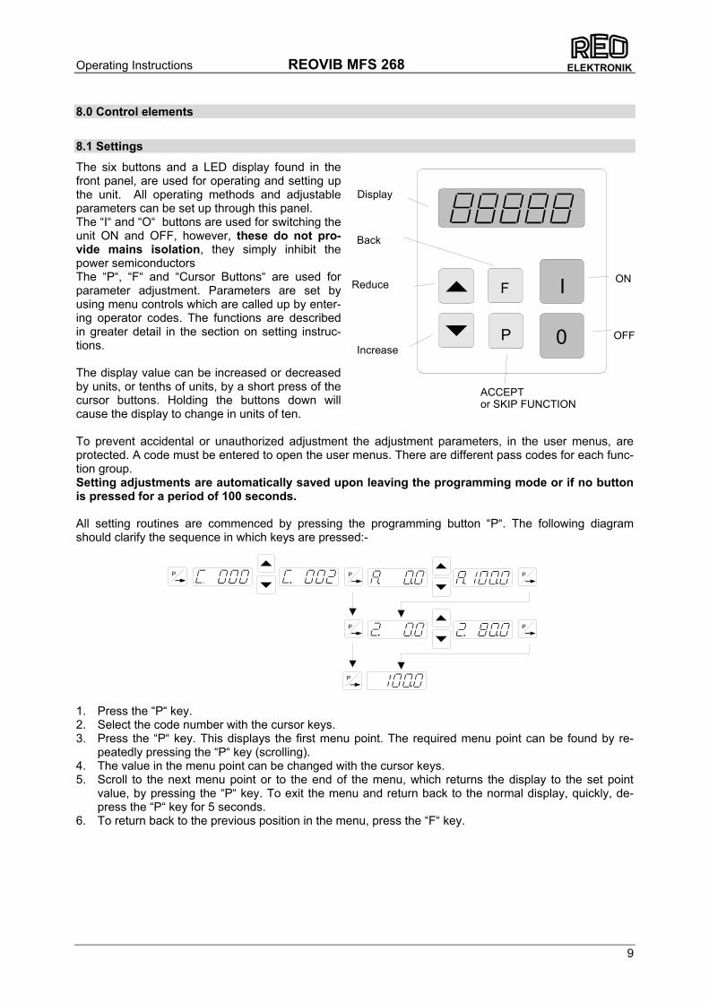
The six buttons and a LED display found in the front panel, are used for operating and setting up the unit. All operating methods and adjustable parameters can be set up through this panel. The “I“ and “O“ buttons are used for switching the unit ON and OFF, however, these do not pro-vide mains isolation, they simply inhibit the power semiconductors The “P“, “F“ and “Cursor Buttons“ are used for parameter adjustment. Parameters are set by using menu controls which are called up by enter-ing operator codes. The functions are described in greater detail in the section on setting instruc-tions. The display value can be increased or decreased by units, or tenths of units, by a short press of the cursor buttons. Holding the buttons down will cause the display to change in units of ten. To prevent accidental or unauthorized adjustment the adjustment parameters, in the user menus, are protected. A code must be entered to open the user menus. There are different pass codes for each func-tion group. Setting adjustments are automatically saved upon leaving the programming mode or if no button is pressed for a period of 100 seconds. All setting routines are commenced by pressing the programming button “P“. The following diagram should clarify the sequence in which keys are pressed:-
1. Press the “P“ key. 2. Select the code number with the cursor keys. 3. Press the “P“ key. This displays the first menu point. The required menu point can be found by re-
peatedly pressing the “P“ key (scrolling). 4. The value in the menu point can be changed with the cursor keys. 5. Scroll to the next menu point or to the end of the menu, which returns the display to the set point
value, by pressing the “P“ key. To exit the menu and return back to the normal display, quickly, de-press the “P“ key for 5 seconds.
6. To return back to the previous position in the menu, press the “F“ key.
P P
P
P
P P
Operating Instructions REOVIB MFS 268
10
ELEKTRONIK
9.0 Commissioning
9.1 Assembling position
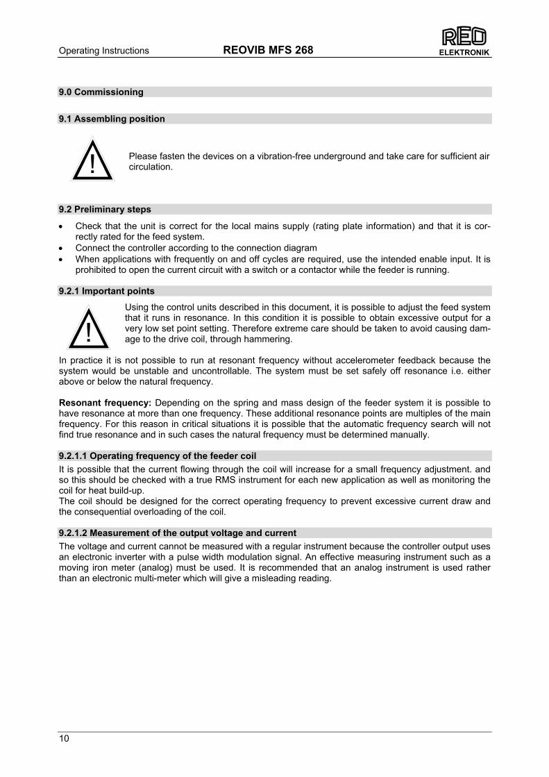
Please fasten the devices on a vibration-free underground and take care for sufficient air circulation.
9.2 Preliminary steps
• Check that the unit is correct for the local mains supply (rating plate information) and that it is cor-rectly rated for the feed system.
• Connect the controller according to the connection diagram • When applications with frequently on and off cycles are required, use the intended enable input. It is
prohibited to open the current circuit with a switch or a contactor while the feeder is running. 9.2.1 Important points
Using the control units described in this document, it is possible to adjust the feed system that it runs in resonance. In this condition it is possible to obtain excessive output for a very low set point setting. Therefore extreme care should be taken to avoid causing dam-age to the drive coil, through hammering.
In practice it is not possible to run at resonant frequency without accelerometer feedback because the system would be unstable and uncontrollable. The system must be set safely off resonance i.e. either above or below the natural frequency. Resonant frequency: Depending on the spring and mass design of the feeder system it is possible to have resonance at more than one frequency. These additional resonance points are multiples of the main frequency. For this reason in critical situations it is possible that the automatic frequency search will not find true resonance and in such cases the natural frequency must be determined manually. 9.2.1.1 Operating frequency of the feeder coil It is possible that the current flowing through the coil will increase for a small frequency adjustment. and so this should be checked with a true RMS instrument for each new application as well as monitoring the coil for heat build-up. The coil should be designed for the correct operating frequency to prevent excessive current draw and the consequential overloading of the coil. 9.2.1.2 Measurement of the output voltage and current The voltage and current cannot be measured with a regular instrument because the controller output uses an electronic inverter with a pulse width modulation signal. An effective measuring instrument such as a moving iron meter (analog) must be used. It is recommended that an analog instrument is used rather than an electronic multi-meter which will give a misleading reading.
!
!
Operating Instructions REOVIB MFS 268
11
ELEKTRONIK
9.3 Putting the equipment into operation
1. Establish the vibrating frequency. 2. Establish the power of the feed system (maximum permissible current draw). For a new feeder where settings are unknown: (see also comments below) Without connecting the feeder, select parameter FAC in menu C210 (reset factory settings), press the cursor key to reset (SAFE) and press the P key to leave the menu. The factory settings are listed in the table in section 7, headed settings ! Comments ! It is possible that a special parameter set, for a machine manufacturer, has been pre-stored under a user code and these can be recalled. In such instances specific machine settings will be loaded and so the next steps are not relevant. Basic settings: • Connect feeder. • Set frequency (refer to feeder data sheet). Menu C096 parameter F. • Check current limit (refer to feeder data sheet). Menu C040 parameter I (shows the current limit as a
percentage of maximum). If applicable use service menu for setting. • Increase set point, observe feeder, check running. • Increase set point to maximum and check if power needs limiting (hammering). If necessary adjust
the limit as follows:- • Adjust set point to zero • Set parameter P (maximum limit) in Menu C096 to 50 • Adjust set point A to 100%. • Increase the maximum limit P from 50% until the required amplitude is reached. • The full set point range of 0…100% can now be used. Additional settings e.g. soft start, time delays etc. can be set to suit the particular equipment. Determining the output frequency (vibrating frequency) It is essential that the output frequency is adjusted with the set point set at a low frequency, otherwise on hitting the resonant frequency it is possible to achieve a high amplitude with a low output voltage. An ana-log, effective value, current indicating unit (moving iron meter) must be connected into the output circuit. Resonant is reached when there is a maximum amplitude for a minimum output current. To achieve a stable feed system there must be an offset between the vibrating frequency and resonance (approx. 1…2Hz). This offset must be determined by the user because different feeders have different running characteristics.

Operating Instructions REOVIB MFS 268
12
ELEKTRONIK
10.0 Setting Instructions
10.1 User adjustment of throughput
Code C. 000
A further set point code can be found under C002 (for use in coarse/fine operation)
10.2 Tuning the feed system
10.2.1 Feeder settings
Code C. 020, 096
Setting the maximum limit
1. Adjust set point to zero 2. Set parameter P (maximum limit) to 50. 3. Adjust set point to 100% 4. Increase the limit P from 50% until the required amplitude is reached 5. The full set point range of 0…100% can now be used
Feeder amplitude set point0...100 %
Running mode
P P P
P
P P
P
P
P
P
Feeder amplitude set point0...100 %
2nd Feeder amplitude set point0...100%(only if "SP.2. = I)
Running mode
Soft start 0...60
Soft stop 0...60
Running
P P
P
P
P
P
P
P
P
P
P
P
F Vibration frequency
Max. output 100...5

Operating Instructions REOVIB MFS 268
13
ELEKTRONIK
10.2.2 Track control
10.2.3 Sensor time out
0 = Sensor time out not active I = Sensor time out active
E. = Sensor time out [sec.]
P P
P
Code C. 015
P
Running modeP
P Ai. = switch off time air valve 0...60 Sec.
On time delay 0...60 sec.
Off time delay 0...60 sec.
0 = No sensor inverting I = Sensor inverting
Code C. 167, 007
0 = Sensor time out not active I = Sensor time out active
E. = Sensor time out [sec.]
P P
P
P
P
P
P
P
P
P
F
Running modeP
Operating Instructions REOVIB MFS 268
14
ELEKTRONIK
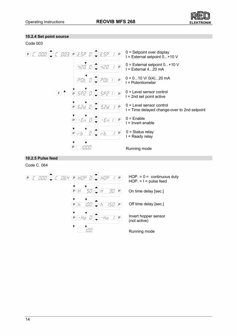
10.2.4 Set point source
10.2.5 Pulse feed
Code C. 064
Off time delay [sec.]
Invert hopper sensor(not active)
Running mode
On time delay [sec.]
HOP. = 0 = continuous dutyHOP. = I = pulse feed
P
P
P
PP
P
P
P P
P P P
P
P
P
P
P
P
F
P
Code 003
PP
PP
0 = EnableI = Invert enable
0 = Level sensor controlI = 2nd set point active
0 = Setpoint over displayI = External setpoint 0...+10 V
0 = External setpoint 0...+10 VI = External 4...20 mA
Running mode
0 = 0...10 V/ 0(4)...20 mAI = Potentiometer
0 = Level sensor controlI = Time delayed change-over to 2nd setpoint
0 = Status relayI = Ready relay
Operating Instructions REOVIB MFS 268
15
ELEKTRONIK
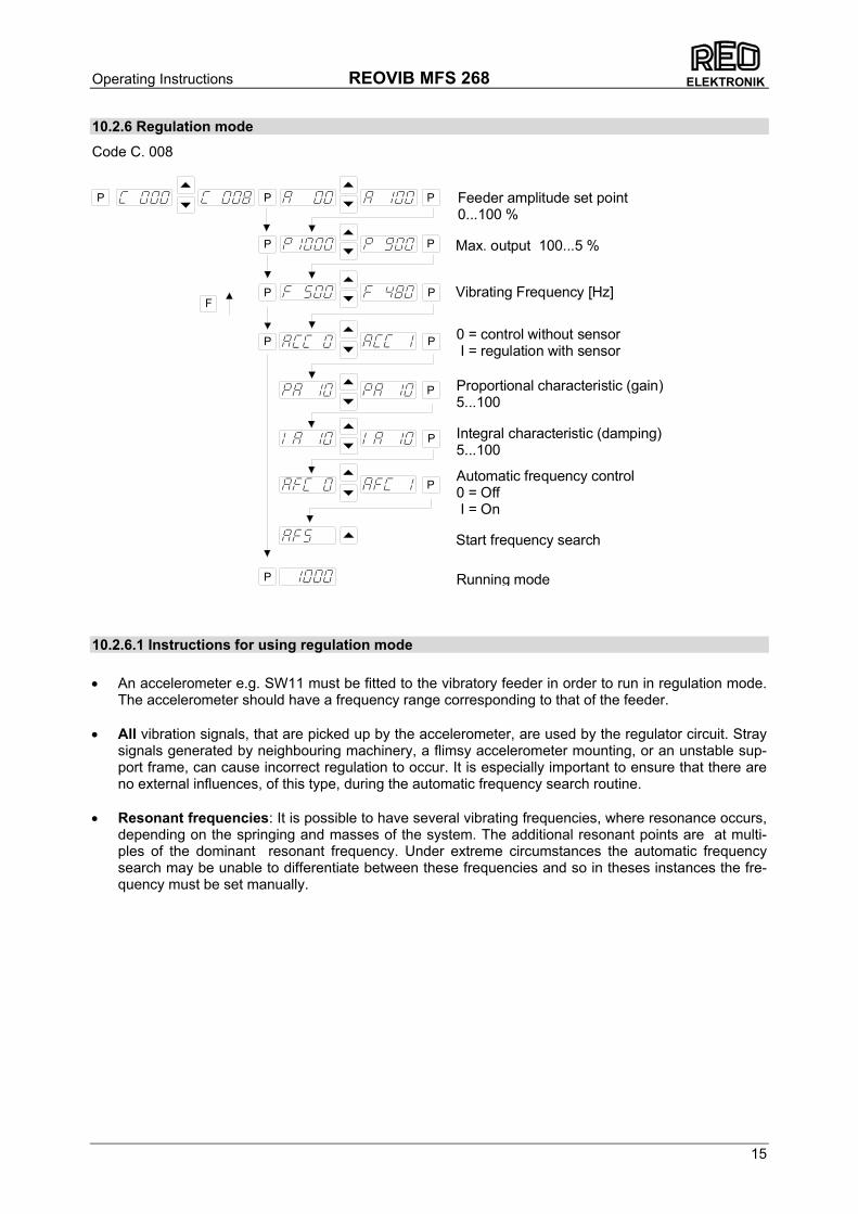
10.2.6 Regulation mode
Code C. 008
10.2.6.1 Instructions for using regulation mode • An accelerometer e.g. SW11 must be fitted to the vibratory feeder in order to run in regulation mode.
The accelerometer should have a frequency range corresponding to that of the feeder. • All vibration signals, that are picked up by the accelerometer, are used by the regulator circuit. Stray
signals generated by neighbouring machinery, a flimsy accelerometer mounting, or an unstable sup-port frame, can cause incorrect regulation to occur. It is especially important to ensure that there are no external influences, of this type, during the automatic frequency search routine.
• Resonant frequencies: It is possible to have several vibrating frequencies, where resonance occurs,
depending on the springing and masses of the system. The additional resonant points are at multi-ples of the dominant resonant frequency. Under extreme circumstances the automatic frequency search may be unable to differentiate between these frequencies and so in theses instances the fre-quency must be set manually.
Vibrating Frequency [Hz]
Max. output 100...5 %
P P
P
P
P
P
P
P
P
P
P
P
P
F
Feeder amplitude set point0...100 %
Proportional characteristic (gain)5...100
Start frequency search
Automatic frequency control0 = Off I = On
Integral characteristic (damping)5...100
0 = control without sensor I = regulation with sensor
Running mode

Operating Instructions REOVIB MFS 268
16
ELEKTRONIK
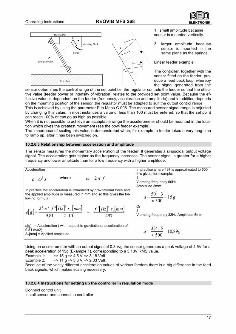
10.2.6.2 Mounting the accelerometer
The accelerometer should generate signals for the movement and acceleration of the feeder, which are fed back to the regulator circuit of the control unit. Therefore it is very important that no other extraneous vibration signals are picked up by the sensor
The sensor should be positioned, that it moves in the same direction as the feeder, ideally in the same plane as the springs. It should be fitted on a solid block that will not generate vibration sig-nals.
In regulation mode the magnitude of the output signal has a direct affect on the maximum ampli-tude of the feeder. On bowl feeders it is advisable to fit the sensor as near as possible to the outside diameter and in this position it will be subjected to the greatest movement
The control range of the set point will be considerably reduced when the sensor signal is weak. s = deflection Mounting position 1 = small deflection Mounting position 2 = large deflection
1 2
21
s
SW SW
Operating Instructions REOVIB MFS 268
17
ELEKTRONIK
1. small amplitude because sensor is mounted vertically. 3. larger amplitude because
sensor is mounted in the same plane as the springs.
Linear feeder example The controller, together with the sensor fitted on the feeder, pro-duce a feed back loop, whereby the signal generated from the
sensor determines the control range of the set point i.e. the regulator controls the feeder so that the effec-tive value (feeder power or intensity of vibration) relates to the provided set point value. Because the ef-fective value is dependent on the feeder (frequency, acceleration and amplitude) and in addition depends on the mounting position of the sensor, the regulator must be adapted to suit the output control range. This is achieved by using the parameter P in Menu C 008. The measured sensor signal range is adjusted by changing this value. In most instances a value of less than 100 must be entered, so that the set point can reach 100% or can go as high as possible. When it is not possible to achieve an acceptable range the accelerometer should be mounted in the loca-tion which gives the greatest movement (see the bowl feeder example). The importance of scaling this value is demonstrated when, for example, a feeder takes a very long time to ramp up, after it has been switched on. 10.2.6.3 Relationship between acceleration and amplitude
The sensor measures the momentary acceleration of the feeder. It generates a sinusoidal output voltage signal. The acceleration gets higher as the frequency increases. The sensor signal is greater for a higher frequency and lower amplitude than for a low frequency with a higher amplitude. Acceleration In practice the acceleration is influenced by gravitational force and the applied amplitude is measured in mm and so this gives the fol-lowing formula:
[ ] [ ] [ ] [ ] [ ]49710281,9
2 22
3
2222 mmsHzfmmsHzfga nn =
⋅=
π
a[g] = Acceleration ( with respect to gravitational acceleration of 9.81 m/s2) Sn[mm] = Applied amplitude
In practice where 497 is approximated to 500 this gives, for example: 1. Vibrating frequency 50Hz Amplitude 3mm Or 2. Vibrating frequency 33Hz Amplitude 5mm
Using an accelerometer with an output signal of 0.3 V/g the sensor generates a peak voltage of 4.5V for a peak acceleration of 15g (Example 1), corresponding to a 3.18V RMS value. Example 1: => 15 g => 4,5 V => 3,18 Veff. Example 2: => 11 g => 3,3 V => 2,33 Veff. Because of the vastly different acceleration values of various feeders there is a big difference in the feed back signals, which makes scaling necessary. 10.2.6.4 Instructions for setting up the controller in regulation mode
Connect control unit Install sensor and connect to controller
fπω 2=sa 2ω=
ga 15500
3502
=≈
⋅=
where
ga 89,10500
5332
=≈
⋅=
Sensor
Swing Direction
Mounting Block
Moving Part
Fixed Part
1
2

Operating Instructions REOVIB MFS 268
18
ELEKTRONIK
10.2.6.5 Determining the resonant frequency
Manual setting of the vibrating frequency It is essential that the output frequency is adjusted with the set point set at a low frequency, otherwise on hitting the resonant frequency it is possible to achieve a high amplitude with a low output voltage. An ana-log, effective value, current indicating unit (moving iron meter) must be connected into the output circuit. Resonant frequency is reached when there is a maximum amplitude for a minimum output cur-rent. Automatic frequency search • The feeder should be empty for a frequency search • Adjust the set point to zero • Select regulation mode (Menu C 008, Parameter ACC = I ) • The optimum frequency of the feeder is found, automatically, by initiating the frequency search (Menu
C 008, Parameter A.F.S.). When this has been found the controller resets the set point back to its original value (0).
10.2.6.6 Optimisating controller in regulation mode
Setting the control range 1. In Menu C. 096 set parameter P (Max Limit) to 50 % 2. Set A (Feeder throughput) to 100% 3. Increase limit P from 50% until the required maximum feeder throughput is achieved The full set point adjustment range of 0…100% can now be used Optimising regulation: For unwanted feeder oscillation (hunting) or inadequate feedback regula-tion for load changes The response of the regulation circuit can be adjusted in menu C008 using the parameter PA (Propor-tional characteristic or circuit gain) and IA (Integral characteristic) In menu C008 reduce PA until the oscillations are reduced Parameter IA should be set to at 100 if possible
Operating Instructions REOVIB MFS 268
19
ELEKTRONIK
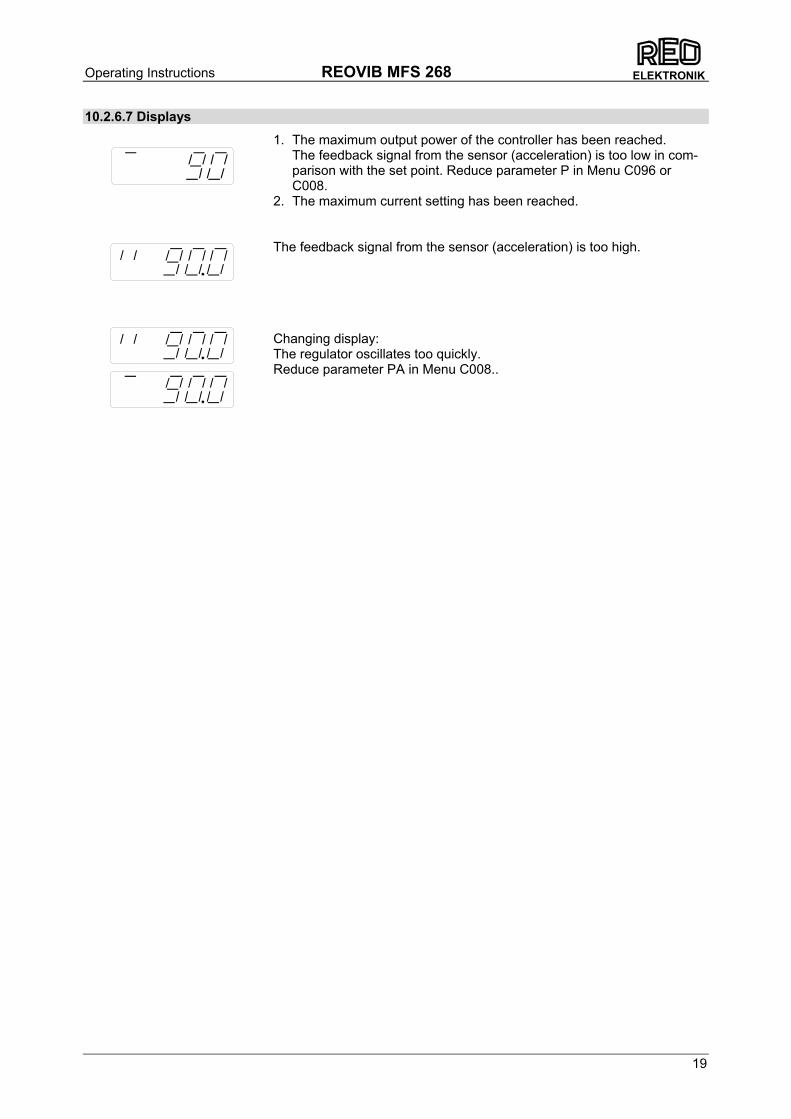
10.2.6.7 Displays
1. The maximum output power of the controller has been reached. The feedback signal from the sensor (acceleration) is too low in com-parison with the set point. Reduce parameter P in Menu C096 or C008.
2. The maximum current setting has been reached.
The feedback signal from the sensor (acceleration) is too high.
Changing display: The regulator oscillates too quickly. Reduce parameter PA in Menu C008..

Operating Instructions REOVIB MFS 268
20
ELEKTRONIK
10.2.7 Display actual current and frequency
Code C. 040
10.2.8 Save selected parameters
Code C. 143
10.2.9 Recall user or factory settings
Code C. 210
10.2.10 Hide parameter menus
Code C. 117
Running mode
P P
P
P Actual current (display only)
P P Actual frequency (display only)
I = Hide menus
Running mode
P P
P
P
Save new parameters
Running mode
P P
P P
P Choose user parameter set
Return to factorysettings
Return to usersettings
Running mode
P P
P
P
P
P
P P Choose user parameter set
Operating Instructions REOVIB MFS 268
21
ELEKTRONIK
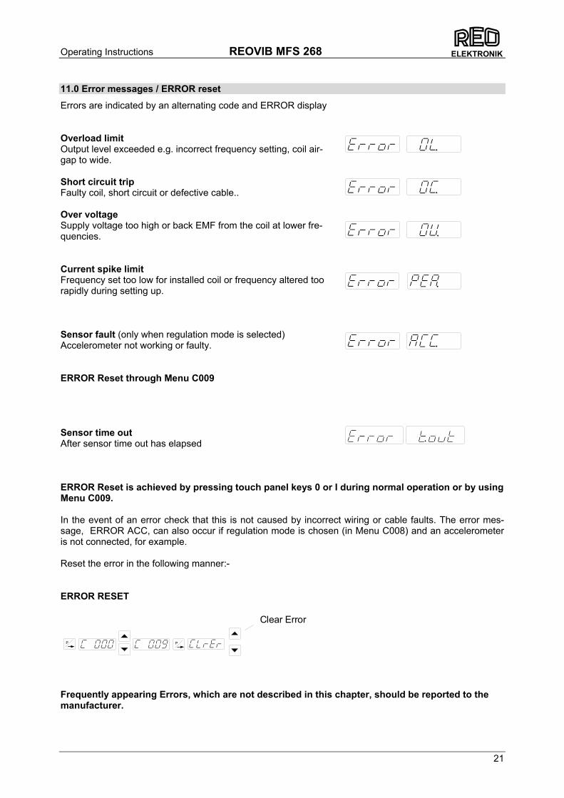
11.0 Error messages / ERROR reset
Errors are indicated by an alternating code and ERROR display Overload limit Output level exceeded e.g. incorrect frequency setting, coil air-gap to wide. Short circuit trip Faulty coil, short circuit or defective cable.. Over voltage Supply voltage too high or back EMF from the coil at lower fre-quencies. Current spike limit Frequency set too low for installed coil or frequency altered too rapidly during setting up. Sensor fault (only when regulation mode is selected) Accelerometer not working or faulty. ERROR Reset through Menu C009 Sensor time out After sensor time out has elapsed ERROR Reset is achieved by pressing touch panel keys 0 or I during normal operation or by using Menu C009. In the event of an error check that this is not caused by incorrect wiring or cable faults. The error mes-sage, ERROR ACC, can also occur if regulation mode is chosen (in Menu C008) and an accelerometer is not connected, for example. Reset the error in the following manner:- ERROR RESET
Frequently appearing Errors, which are not described in this chapter, should be reported to the manufacturer.
P P
Clear Error
Operating Instructions REOVIB MFS 268
22
ELEKTRONIK
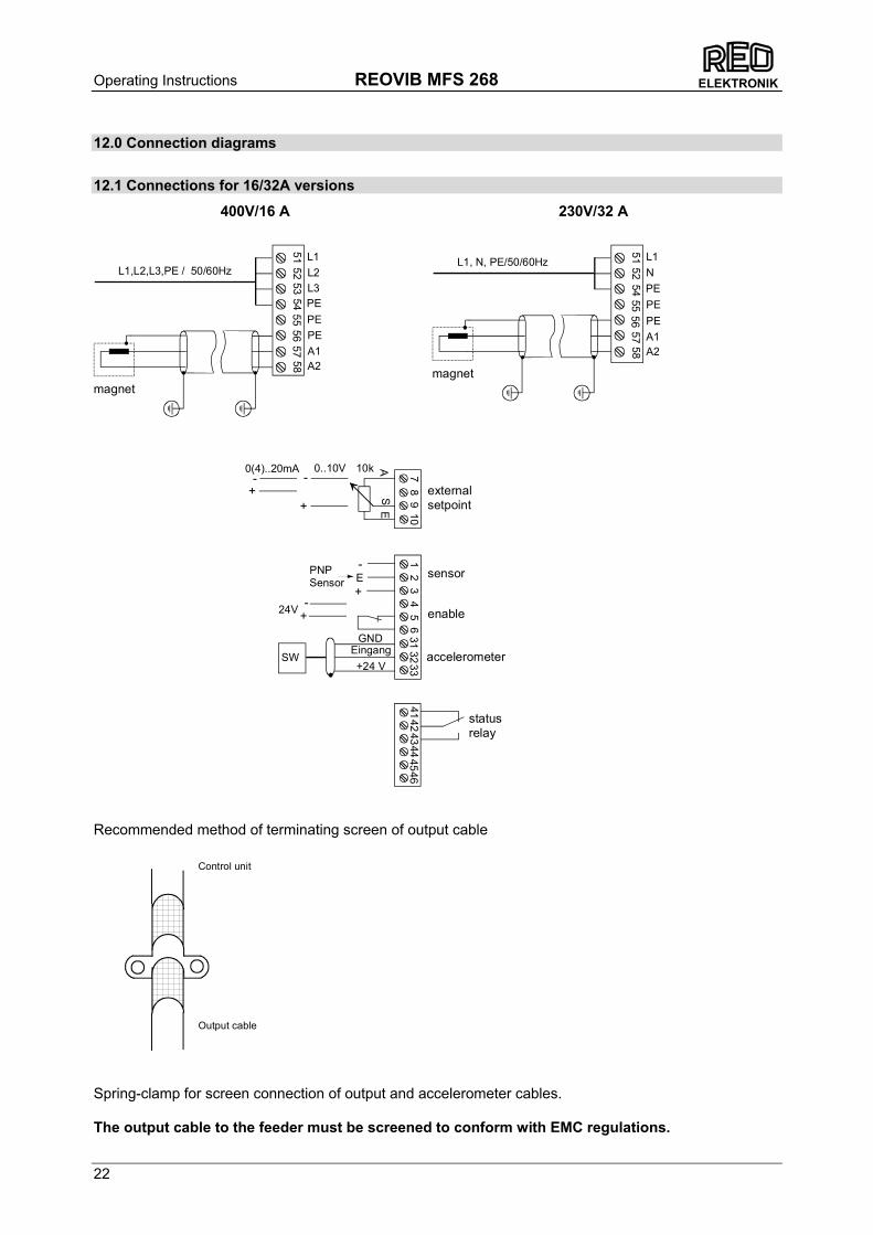
12.0 Connection diagrams
12.1 Connections for 16/32A versions
Recommended method of terminating screen of output cable
Spring-clamp for screen connection of output and accelerometer cables. The output cable to the feeder must be screened to conform with EMC regulations.
Output cable
Control unit
0..10V
+
-
24V
5556
5751
5253
5458
L1
A2A1
PEPE
L1,L2,L3,PE / 50/60Hz
56
71
23
48
9
E
ES
A10k
+
+
-
-
+24 VSW
313233
10
400V/16 A
PNPSensor
EingangGND
L2L3
PE
0(4)..20mA
+ -4546
41424344
magnet
5556
5751
5254
58
L1
A2A1
PEPE
L1, N, PE/50/60HzN
PE
magnet
230V/32 A
externalsetpoint
sensor
enable
accelerometer
statusrelay
Operating Instructions REOVIB MFS 268
23
ELEKTRONIK
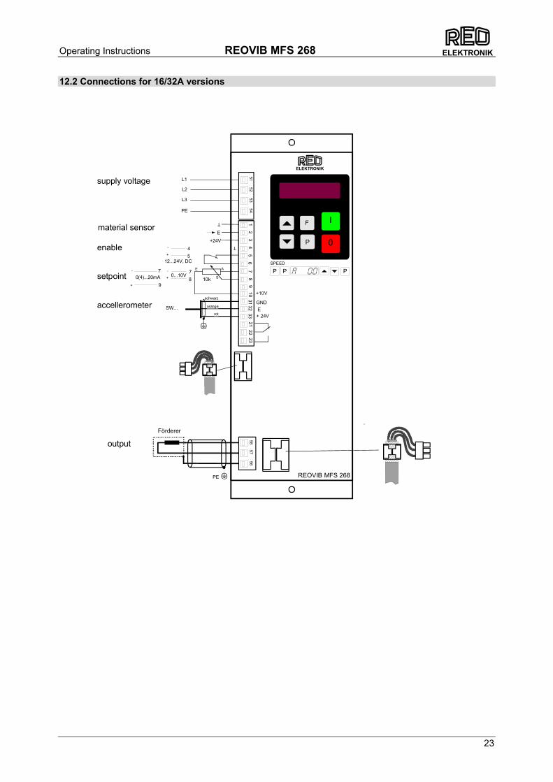
12.2 Connections for 16/32A versions
56
71
23
48
9
E
+24V
E
S
A
10k
PE
0...10V0(4)...20mA +
+
- -7
9
78
21
+10V
2258
5756
12...24V, DC+
- 45
E+ 24V
3132
33SW...
L1
L2
L3
PE
5152
5354
10GND
23
REOVIB MFS 268
ELEKTRONIK
P P PSPEED
I
0P
Fmaterial sensor
Förderer
enable
setpoint
accellerometer
supply voltage
orange
schwarz
rot
output
Operating Instructions REOVIB MFS 268
24
ELEKTRONIK
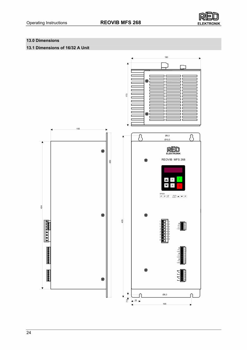
13.0 Dimensions
13.1 Dimensions of 16/32 A Unit
Ø6,0
Ø6,0
Ø10,5
7,5
435
450
25
165
155
31 32 3321 22 23 26 27 28
123456
+24V
+24V
+24V
51 52 53 54 55 56 57 58
L1 L2 L3 PE
PE P
E A1 A2
REOVIB MFS 268
1 2 3 4 5 6 31 32 3321 22 23 26 27 28
404
51 52 53 54 55 56 57 58
173
190
+10V
7 8 910
7 8 9 10
I
0P
F
ELEKTRONIK
P P PSPEED
Operating Instructions REOVIB MFS 268
25
ELEKTRONIK
56
71
23
48
921
+10V
2224
2529
E+ 24V
3132
3326
2728
2910
GND
23
REOVIB MFS 268
ELEKTRONIK
P P PSPEED
104
300
210
250
I
0P
F28
86,
5
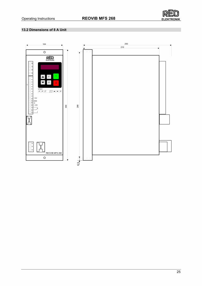
13.2 Dimensions of 8 A Unit
Operating Instructions REOVIB MFS 268
26
ELEKTRONIK
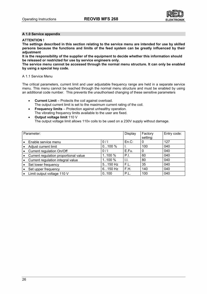
A 1.0 Service appendix
ATTENTION ! The settings described in this section relating to the service menu are intended for use by skilled persons because the functions and limits of the feed system can be greatly influenced by their adjustment It is the responsibility of the supplier of the equipment to decide whether this information should be released or restricted for use by service engineers only. The service menu cannot be accessed through the normal menu structure. It can only be enabled by using a special key code. A 1.1 Service Menu The critical parameters, current limit and user adjustable frequency range are held in a separate service menu. This menu cannot be reached through the normal menu structure and must be enabled by using an additional code number. This prevents the unauthorised changing of these sensitive parameters
• Current Limit – Protects the coil against overload. The output current limit is set to the maximum current rating of the coil.
• Frequency limits – Protection against unhealthy operation. The vibrating frequency limits available to the user are fixed.
• Output voltage limit 110 V The output voltage limit allows 110v coils to be used on a 230V supply without damage.
Parameter: Display Factory
setting: Entry code:
• Enable service menu 0 / I En.C: 0 127 • Adjust current limit 0...100 % I. 100 040 • Current regulation On/Off 0 / I E.Fu. 0 040 • Current regulation proportional value 1..100 % P.I. 60 040 • Current regulation integral value 1..100 % I.I. 80 040 • Set lower frequency 5...150 Hz F.L. 35 040 • Set upper frequency 6...150 Hz F.H. 140 040 • Limit output voltage 110 V 0..100 P.L. 100 040
Operating Instructions REOVIB MFS 268
27
ELEKTRONIK
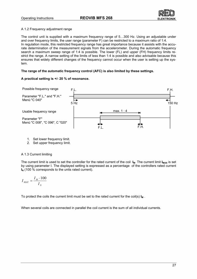
A 1.2 Frequency adjustment range The control unit is supplied with a maximum frequency range of 5…300 Hz. Using an adjustable under and over frequency limits, the user range (parameter F) can be restricted to a maximum ratio of 1:4. In regulation mode, this restricted frequency range has great importance because it assists with the accu-rate determination of the measurement signals from the accelerometer. During the automatic frequency search a maximum sweep range of 1:4 is possible. The lower (FL) and upper (FH) frequency limits re-strict the range. A narrow setting of the limits of less than 1:4 is possible and also advisable because this ensures that widely different changes of the frequency cannot occur when the user is setting up the sys-tem. The range of the automatic frequency control (AFC) is also limited by these settings. A practical setting is +/- 20 % of resonance.
1. Set lower frequency limit. 2. Set upper frequency limit.
A 1.3 Current limiting The current limit is used to set the controller for the rated current of the coil IM. The current limit IMAX is set by using parameter I. The displayed setting is expressed as a percentage of the controllers rated current IN (100 % corresponds to the units rated current).
To protect the coils the current limit must be set to the rated current for the coil(s) IM . When several coils are connected in parallel the coil current is the sum of all individual currents.
N
MMAX I
II 100⋅=
5 Hz 150 Hz
F.L. F.H.
F.L. F.H.
max. 1 : 4
Possible frequency range
Parameter "F.L." and "F.H."Menü "C 040"
Usable frequency range
Parameter "F"Menü "C 008", "C 096", C "020"

Operating Instructions REOVIB MFS 268
28
ELEKTRONIK
Enable Service Mode The actual service menu is accesed by opening the service mode.
The normal service menu, containing the output current and frequency limit settings, is accessed by opening the service mode. Servicemenu
After making adjustments the service mode must be closed again!
0 = Service mode off I = Service mode on
P P
P
P
Running mode
Code 040
P P
P
P
P
P
P
P
P
PF
P P
P P
P P
P P
P P
High frequency limit
Low frequency limit
Current limit in % of Imax.
Actual current (just display)
Actual frequency (just display)
Output voltage limit ("P.Li. 0" = 205 V, P.Li. I" = 100 V)
E.Fu. = 0 Current regulation OnE.Fu. = I Current regulation Off
Current regulation proportional value
Current regulation integral value