Embed Size (px)
Citation preview

Control MountInstruction Manual
CM-IW2000
CM-IW2000 Instruction Manual2
IntroductionThe iPort® Control Mount is an in-wall mounting platform system that allows an iPad® to become an integral part of your home control system through wireless applications. Before installing and using the CM-IW2000, please read and follow all of the instructions in this manual carefully.
System Capabilities:• Rigidly supports the iPad and provides a modern elegant
appearance• Charges the iPad while it is mounted.
iPort Control Mount Box Contents: (1) iPort in-wall mounting system (1) Power wall plate (1) Regulated power supply (1) Installation cut-out template (1) Instruction manual (1) Suction cup removal tool (1) Circuit board assembly (10) Machine screws with integral washers
Required ToolsThe following tools are required to install the iPort:
• #1 Phillips screwdriver• #2 Phillips screwdriver• Wire cutters and wire strippers• RJ-45 cable crimp tool and modular connectors• Sheet rock saw (for retrofitting into an existing wall)
Selecting an Installation LocationThe iPort Control Mount is designed for use in normal interior environments. When selecting location for the Control Mount, please consider the following:
• Do not use the Control Mount outside or in a humid or wet environment. It is not waterproof or water-resistant.
• The Control Mount cut-out must have enough depth within the wall cavity for the Control Mount and its connections.
• Check for a strong Wi-Fi signal at the mounting location using the iPad that is to be installed in the Control Mount.
Control Mount Rear ConnectionThe CM-IW2000 features an RJ-45 jack to connect to the powered wall plate via Cat5 cable. The power connection receives DC power through the RJ45 connector as shown in figure 1.
Wiring Cat5/RJ-45 CableThe Cat5 cable and RJ-45 connector used in iPort installations must be wired according to the T568A (“Straight-Through”) Standard with cables wired identically at both ends.
To prepare the Cat5 cable and RJ-45 connector for iPort installation:
1. Pull the Cat5 wire through the wall between the desired locations.
2. Use a stripper or knife to strip about 1” of the cable jacket off each end of the wire.
• Be careful not to nick any of the individual wires.
3. Untwist the wire pairs and spread them flat. Arrange them as shown in Figure 2.
4. Trim the ends of the individual wires to ½” in length, making sure they are even with each other. Flatten the wires against each other, leaving no space between them.
5. Hold the RJ-45 connector clip-side down and insert the Cat5 wire ends firmly into the connector. Make sure that all the wires are flat all the way to the very front of the connector.
6. Re-confirm the color orientation matches the diagram and cable jacket fits against the connector stop.
7. Firmly crimp the RJ-45 connector with the crimp tool. Confirm the connector is crimped firmly and all the wires are flat right up against the front of the connector. If even one of these wires is incorrect, cut the connector off the cable and repeat steps 2 – 7 with a new RJ-45 connector.
Figure 2: RJ-45 Power ConnectorFigure 1: iPort Rear Connection
RJ-45 Jack
21 3 4
POWER INTERNETWIRELESS
ETHERNET PORT
To AudioWall Plate
CM-IW100T
®
U.S. Patent No. 7,493,142Additional Patents Pending
Designed and Engineered in the USA33-5203 4-09
CM-IW2000 Instruction Manual 3
Installation PreparationThe CM-IW2000 features an integral Roto-Lock® mounting system for quick mounting directly into existing walls. Once the hole is cut and the cables have been run, you can install the iPort into the wall in a matter of seconds.1. Determine the location for the iPort Control Mount and the
wall plate.
2. Perform an obstruction survey to ensure there are no studs, conduit, pipes, heating ducts, or air returns that will interfere with the Control Mount.
3. Find the cut-out template provided in the CM-IW2000 packaging. Place in appropriate location between wall studs. Verify there are no horizontal fire blocks with-in cut out area. Place level on template to assure a level opening. Position the template where the Control Mount is to be located and pencil an outline on the wall.
Note: Be sure to confirm the installation of the iPort at this time for either vertical (portrait) or horizontal (landscape) orientation. Certain applications of the mounted iPad work only in one orientation, so be sure to confirm the client’s requirements before cutting the hole.
• If you are unsure about obstructions, drill a small hole in the center of the outline and insert a coat hanger wire into the hole to feel around for possible obstructions.
4. Cut the opening using a drywall saw.
5. After cutting the opening, make sure the edges of opening are smooth so frame flange will rest flat against wall.
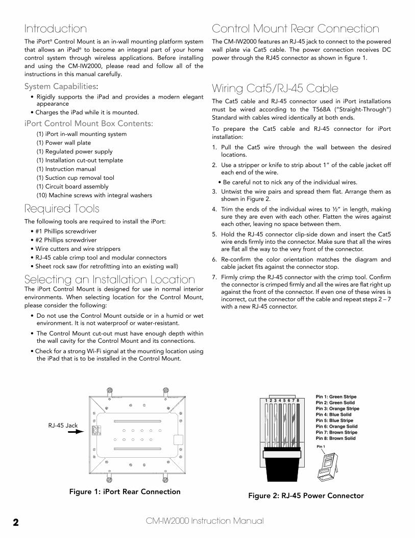
iPort Connection and InstallationSee Figure 31. Before making connections, run a length of Cat5 cable through
the wall from the Control Mount location to the power wall plate location, as shown in Figure 3. The wall plate can be located up to 30 feet from the control mount.
2. Install RJ-45 connectors on both ends of the Cat5 cable as explained in Figure 2: Cat5 / RJ-45 Power connector. The Cat5/RJ-45 cable pin assignment is:
3. Plug the Cat5 cable into the RJ-45 jack on the Control Mount and the RJ-45 jack on the wall plate, as shown in Figure 3.
4. Install the wall plate into an electrical box
ImPortaNt: Do not install the iPort’s wall plate in the same electrical box as aC house wiring, a light switch, or any other high-voltage device or control. the wall plate can share gang boxes with other iPort Control mount wall plates or with controls such as a/B speaker switches, infrared receivers, and volume controls, if these other devices are rated as Class 2 devices according to the National Electrical Code.
21 3 4
POWER INTERNETWIRELESS
ETHERNET PORT
To AudioWall Plate
CM-IW100T
®
U.S. Patent No. 7,493,142Additional Patents Pending
Designed and Engineered in the USA33-5203 4-09
Pin 1: UnusedPin 2: UnusedPin 3: UnusedPin 4: Unused
Pin 5: UnusedPin 6: UnusedPin 7: GroundPin 8: +15V
Figure 3: iPort System Connections
CM-IW2000 Instruction Manual4
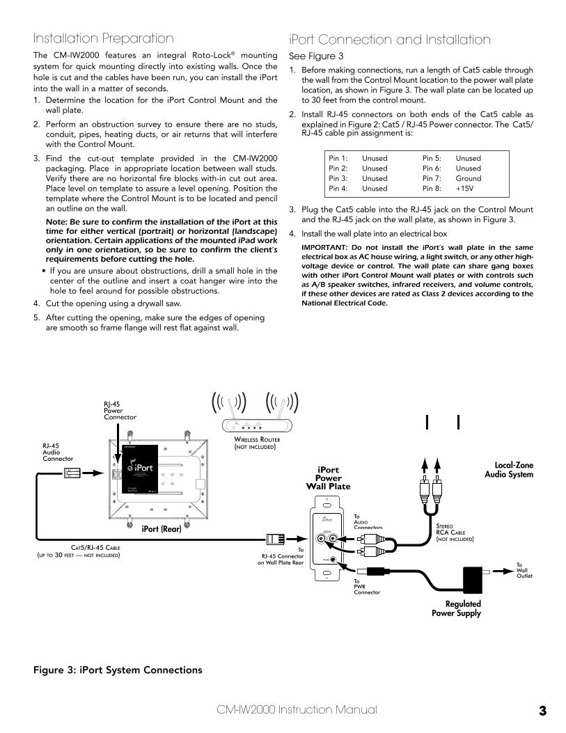
5. Prior to placing the mounting frame into the wall, pull a sufficient length of the Cat5 cable and its attached RJ-45 connector through the opening in the side of the mounting frame, as shown in figure 4.
6. Insert the Control Mount mounting frame into the opening in the wall.
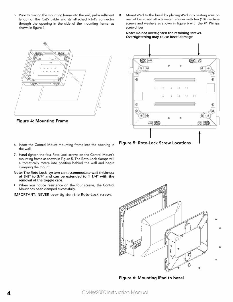
7. Hand-tighten the four Roto-Lock screws on the Control Mount’s mounting frame as shown in Figure 5. The Roto-Lock clamps will automatically rotate into position behind the wall and begin clamping the mount.
Note: the roto-Lock system can accommodate wall thickness of 3/8” to 3/4” and can be extended to 1 1/4” with the removal of the toggle caps.
• When you notice resistance on the four screws, the Control Mount has been clamped successfully.
Important: nEVEr over-tighten the roto-Lock screws.
8. Mount iPad to the bezel by placing iPad into nesting area on rear of bezel and attach metal retainer with ten (10) machine screws and washers as shown in figure 6 with the #1 Phillips screwdriver
Note: Do not overtighten the retaining screws. overtightening may cause bezel damage
Figure 4: Mounting Frame
Figure 5: Roto-Lock Screw Locations
Figure 6: Mounting iPad to bezel
CM-IW2000 Instruction Manual 5
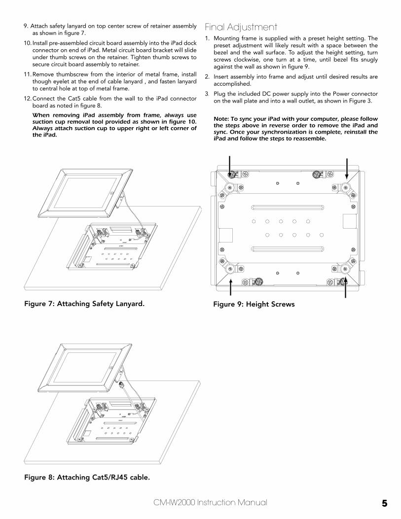
9. Attach safety lanyard on top center screw of retainer assembly as shown in figure 7.
10. Install pre-assembled circuit board assembly into the iPad dock connector on end of iPad. Metal circuit board bracket will slide under thumb screws on the retainer. Tighten thumb screws to secure circuit board assembly to retainer.
11. Remove thumbscrew from the interior of metal frame, install though eyelet at the end of cable lanyard , and fasten lanyard to central hole at top of metal frame.
12. Connect the Cat5 cable from the wall to the iPad connector board as noted in figure 8.
When removing iPad assembly from frame, always use suction cup removal tool provided as shown in figure 10. always attach suction cup to upper right or left corner of the iPad.
Final Adjustment 1. Mounting frame is supplied with a preset height setting. The
preset adjustment will likely result with a space between the bezel and the wall surface. To adjust the height setting, turn screws clockwise, one turn at a time, until bezel fits snugly against the wall as shown in figure 9.
2. Insert assembly into frame and adjust until desired results are accomplished.
3. Plug the included DC power supply into the Power connector on the wall plate and into a wall outlet, as shown in Figure 3.
Note: to sync your iPad with your computer, please follow the steps above in reverse order to remove the iPad and sync. once your synchronization is complete, reinstall the iPad and follow the steps to reassemble.
Figure 7: Attaching Safety Lanyard.
Figure 8: Attaching Cat5/RJ45 cable.
Figure 9: Height Screws
6 CM-IW2000 Instruction Manual
Removal1. Ensure that the CM2000 bezel is not bonded with the wall paint.
If it has, gently place a plastic putty knife under the frame on all sides to ensure the frame doesn’t peel the wall paint while being removed.
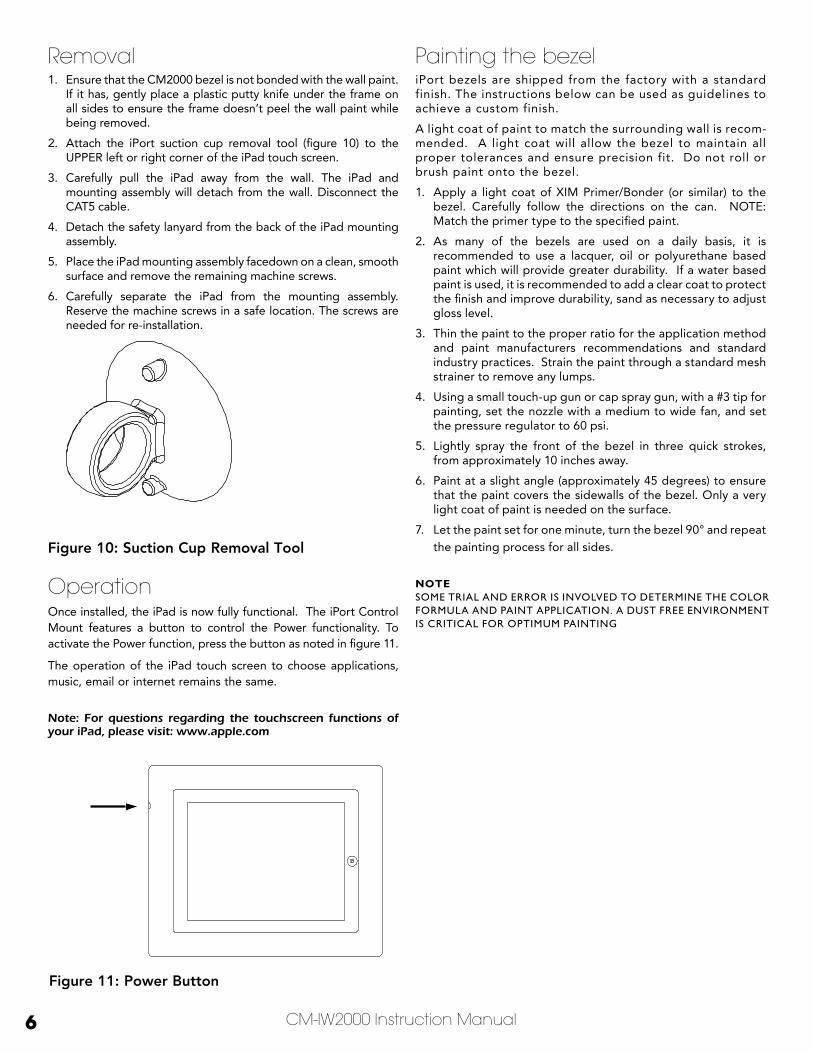
2. Attach the iPort suction cup removal tool (figure 10) to the UPPER left or right corner of the iPad touch screen.
3. Carefully pull the iPad away from the wall. The iPad and mounting assembly will detach from the wall. Disconnect the CAT5 cable.
4. Detach the safety lanyard from the back of the iPad mounting assembly.
5. Place the iPad mounting assembly facedown on a clean, smooth surface and remove the remaining machine screws.
6. Carefully separate the iPad from the mounting assembly. Reserve the machine screws in a safe location. The screws are needed for re-installation.
OperationOnce installed, the iPad is now fully functional. The iPort Control Mount features a button to control the Power functionality. To activate the Power function, press the button as noted in figure 11.
The operation of the iPad touch screen to choose applications, music, email or internet remains the same.
Note: For questions regarding the touchscreen functions of your iPad, please visit: www.apple.com
Figure 11: Power Button
Figure 10: Suction Cup Removal Tool
Painting the bezeliPort bezels are shipped from the factory with a standard finish. The instructions below can be used as guidelines to achieve a custom finish.
A light coat of paint to match the surrounding wall is recom-mended. A light coat will allow the bezel to maintain all proper tolerances and ensure precision fit. Do not roll or brush paint onto the bezel.
1. Apply a light coat of XIM Primer/Bonder (or similar) to the bezel. Carefully follow the directions on the can. NOTE: Match the primer type to the specified paint.
2. As many of the bezels are used on a daily basis, it is recommended to use a lacquer, oil or polyurethane based paint which will provide greater durability. If a water based paint is used, it is recommended to add a clear coat to protect the finish and improve durability, sand as necessary to adjust gloss level.
3. Thin the paint to the proper ratio for the application method and paint manufacturers recommendations and standard industry practices. Strain the paint through a standard mesh strainer to remove any lumps.
4. Using a small touch-up gun or cap spray gun, with a #3 tip for painting, set the nozzle with a medium to wide fan, and set the pressure regulator to 60 psi.
5. Lightly spray the front of the bezel in three quick strokes, from approximately 10 inches away.
6. Paint at a slight angle (approximately 45 degrees) to ensure that the paint covers the sidewalls of the bezel. Only a very light coat of paint is needed on the surface.
7. Let the paint set for one minute, turn the bezel 90° and repeat the painting process for all sides.
NOTEsome trial and error is involved to determine the color formula and paint application. a dust free environment is critical for optimum painting
CM-IW2000 Instruction Manual 7
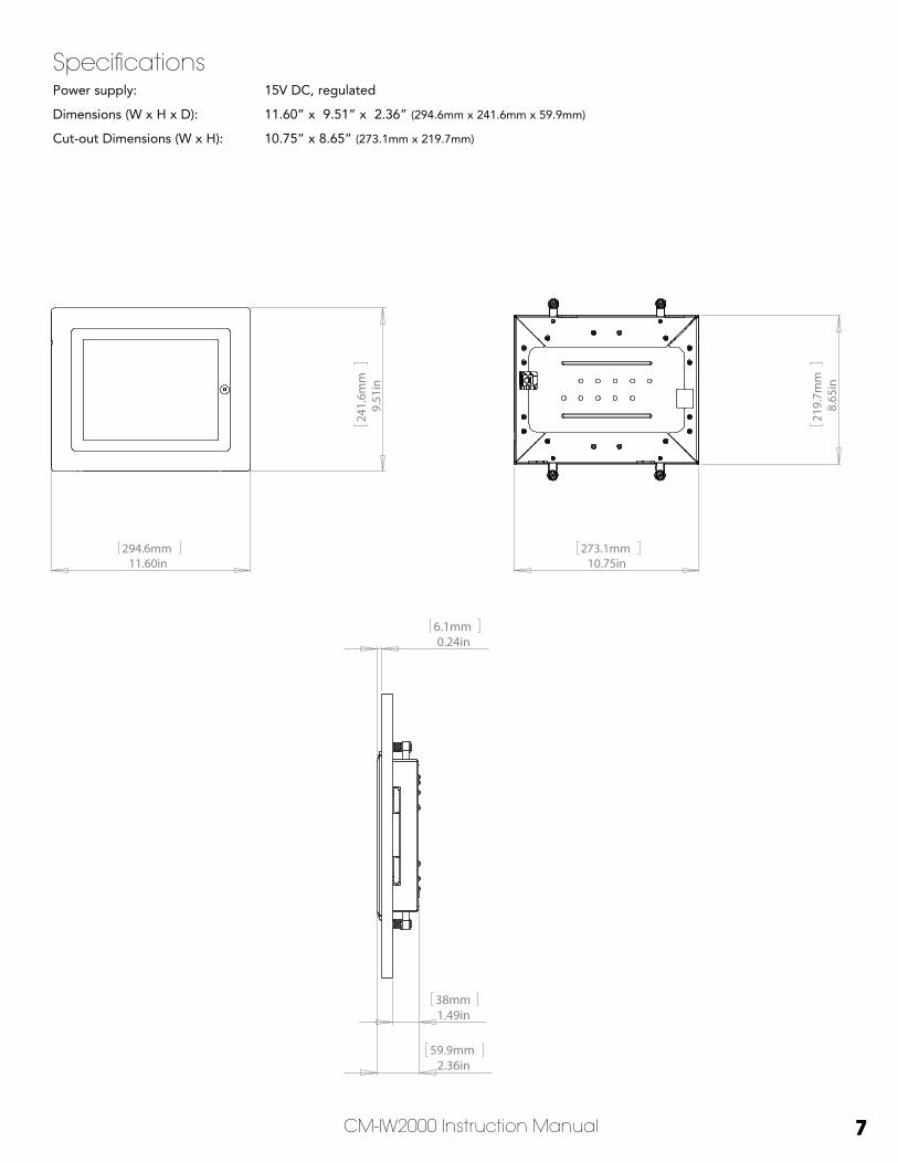
SpecificationsPower supply: 15V DC, regulated
Dimensions (W x H x D): 11.60” x 9.51” x 2.36” (294.6mm x 241.6mm x 59.9mm)
Cut-out Dimensions (W x H): 10.75” x 8.65” (273.1mm x 219.7mm)
11.60in294.6mm
9.51
in24
1.6m
m
1.49in38mm
2.36in59.9mm
0.24in6.1mm
10.75in273.1mm
8.65
in21
9.7m
m
11.60in294.6mm
9.51
in24
1.6m
m
1.49in38mm
2.36in59.9mm
0.24in6.1mm
10.75in273.1mm
8.65
in21
9.7m
m

8
LIMITED ONE (1) YEAR WARRANTYiPort warrants to the first end-user purchaser that this iPort-brand product (“Product”), when purchased from and installed by an authorized iPort Dealer/Distributor, will be free from defective workmanship and materials in the initial installation for the period stated below. iPort will at its option and expense during the warranty period, either repair the defect or replace the Product with a new or remanufactured Product or a reasonable equivalent at no charge for parts, labor and return shipping.
EXCLUSIONSTO THE EXTENT PERMITTED BY LAW, THE WARRANTY SET FORTH ABOVE IS IN LIEU OF, AND EXCLUSIVE OF, ALL OTHER WARRANTIES, EXPRESS OR IMPLIED, AND IS THE SOLE AND EXCLUSIVE WARRANTY PROVIDED BY IPORT. ALL OTHER EXPRESS AND IMPLIED WARRANTIES, INCLUDING THE IMPLIED WARRANTY OF MERCHANTABILITY, IMPLIED WARRANTY OF FITNESS FOR USE, AND IMPLIED WARRANTY OF FITNESS FOR A PARTICULAR PURPOSE ARE SPECIFICALLY EXCLUDED. No one is autho-rized to make or modify any warranties on behalf of iPort.
The warranty stated above is the sole and exclusive remedy and iPort’s performance shall constitute full and final satisfaction of all obligations, liabilities and claims with respect to the Product. IN ANY EVENT, IPORT SHALL NOT BE LIABLE FOR CONSEQUENTIAL, INCIDENTAL, ECONOMIC, PROPERTY, BODILY INJURY, OR PERSONAL INJURY DAMAGES ARISING FROM THE PRODUCT, ANY BREACH OF THIS WARRANTY OR OTHERWISE.
This warranty statement gives you specific legal rights, and you may have other rights which vary from state to state. Some states do not allow the exclusion of implied warranties or limitations of remedies, so the above exclusions and limitations may not apply. If your state does not allow disclaimer of implied warranties, the duration of such implied warranties is limited to the period of iPort’s express warranty.
______________________________________________________________________________
Your Product Model and Description: iPort Control Mount CM-IW2000
Warranty Period for this Product: One (1) year from the date on the original sales receipt, invoice or other satisfactory proof of purchase.
Additional limitations and Exclusions From Warranty Coverage: The warranty described above is non-transferrable, and does not include damage to allied or associated equipment which may result for any reason from use with this Product, and does not include Product failure caused by accident, disaster, negligence, improper installation, misuse (e.g. overdriving the amplifier or speaker, excessive heat or cold or humidity, outdoor installation), or from service or repair which has not been authorized by iPort.
Obtaining Authorized Service: If you purchased your iPort from an iPort Dealer, you (1) must contact your authorized iPort Dealer/Installer or call iPort Customer Service at (800) 582-0772 within the warranty period, (2) must obtain a return merchandise number (RMA), and (3) deliver the Product to iPort shipping prepaid during the warranty period, together with the original sales receipt, invoice or other satisfactory proof of purchase from your iPort Dealer. If you did not purchase from an iPort dealer, you must contact your authorized seller within the warranty period and obtain instructions for obtaining authorized service.
san clemente ca | 888 . 45 . iPort | www.iportmusic.com
©2010 Dana Innovations. All rights reserved. iPort and Roto-Lock are registered trademarks of Dana Innovations.
iPad is a trademark or registered trademark of Apple Inc. “Made for iPad” means that an electronic accessory has been designed to connect specifically to iPad, and has been certified by the developer to meet Apple performance standards.
Apple is not responsible for the operation of this device or its compliance with safety and regulatory standards.
Due to continuous product improvement,all specifications are subject to change without notice.
For the latest iPort product information go to www.iportmusic.com
33-5488 08162010