Embed Size (px)
Citation preview
Bachelor's thesis
Degree programme: Information Technology
Specialisation: Android and Arduino Development
2012
Kishan Raj KC
CONTROLLING A ROBOT USING ANDROID INTERFACE AND VOICE
TURKU UNIVERSITY OF APPLIED SCIENCES, THESIS | Kishan Raj KC
2
2
BACHELOR´S THESIS | ABSTRACT TURKU UNIVERSITY OF APPLIED SCIENCES
Degree programme | Information Technology
October, 2012 | 36
Instructors: Patric Granholm, Sagar Sapkota
The objective of this thesis is to develop a program or an Android app to control a robot
powered by Arduino using a motor driver shield and a Bluetooth modem. The process
involved in building the robot includes the assembling of a chassis used for the robot
and programing the Arduino as well as the interface for the android device.
This thesis documents the design process for the robot and programming for the
android interface. The details in the thesis give the information about the different
aspects of computing involved in whole project.
The outcome of the project is a combination of embedded computing and
programming.
KEYWORDS:
Android, Arduino, Bluetooth shield, embedded computing
3
TABLE OF CONTENTS
1 INTRODUCTION 6
2 ASSEMBLING THE CHASIS 8
2.1 Assembling process 9
3 ARDUINO, ARDUMOTO, BLUETOOTH MODEM AND CIRCUIT DESING 12
3.1 Arduino 12
3.1.1 Arduino history 13
3.1.2 Arduino Hardware 14
3.1.3 Arduino Software 15
3.2 Ardumoto 16
3.3 BlueSMiRF (Bluetooth modem) 17
3.4 Circuit Design 19
3.4.1 Wire connections and Bluetooth placement 20
4 SOFTWARE DESING (ANDROID APP DESING) 21
4.1 App Inventor Designer 23
4.2 App Inventor Blocks Editor 24
4.3 An emulator or Android phone 25
5 MOBOT APPLICATION (Mobile phone operated robot) 26 5.1 Buttons 27
5.1.1 Set Device and Connect Buttons 27
5.1.2 Direction and stop buttons 27
5.1.3 Speak Button 28
6 ROBOT'S WORKING MECHANISM 29
7 CONCLUSION 30
REFERENCES 31
APPENDIX 33
FIGURES Figure 1. Magician chassis parts
Figure 2. Lower panel of chassis
2.1.1 Completion of assembling process 10
TURKU UNIVERSITY OF APPLIED SCIENCES, THESIS | Kishan Raj KC
4
4
Figure 3. Upper panel of chassis
Figure 4. Two gear motors
Figure 5. Two wheels
Figure 6. Connecting gear motors to the lower panel chassis
Figure 7. Connecting wheels to the gear motors
Figure 8. Side view of the chasis
Figure 9. Ariel view of the completed chasis
Figure 10. Final product
Figure 11. Arduino Uno R3
Figure 12. First Prototype
Figure 13. Arduino Uno R3 Schematics
Figure 14. Arduino Software
Figure 15. Ardumoto
Figure 16. Ardumoto Schematics
Figure 17. BlueSMiRF Silver
Figure 18. BlueSMiRF Schematics
Figure 19. Ardumoto overlaid on Arduino
Figure 20. MIT App Inventor
Figure 21. App Inventor Designer
Figure 22. App Inventor Blocks Editor
Figure 23. Android Emulator
Figure 24. Mobot Application Layout
Figure 25. Set Device and Connect Button
Figure 26. Direction and stop Buttons
Figure 27. Speak Function
Figure 28. Bluetooth placement
Figure 29. Robot’s Working Mechanism
5
ACRONYMS, ABBREVIATIONS AND SYMBOLS
OS Operating System
MIT Massachusetts Institute of Technology
App Application
DC Direct Current
IIDI Interaction Design Institute Ivrea
PWM Pulse with modulation
ICSP In-Circuit Serial Programming
SRAM Static random-access memory
EEPROM Electrically Erasable Programmable Read Only Memory
BlueSMiRF Bluetooth Serial Miniature RF
ISM Industrial, scientific and medical
TX Transmit
RX Receive
V Voltage
MHz Mega Hertz
USB Universal Serial Bus
TURKU UNIVERSITY OF APPLIED SCIENCES, THESIS | Kishan Raj KC
6
6
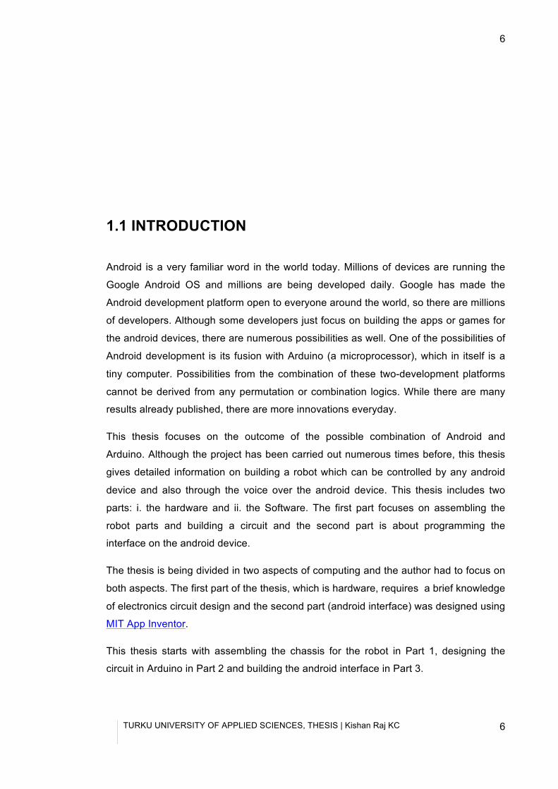
1.1 INTRODUCTION
Android is a very familiar word in the world today. Millions of devices are running the
Google Android OS and millions are being developed daily. Google has made the
Android development platform open to everyone around the world, so there are millions
of developers. Although some developers just focus on building the apps or games for
the android devices, there are numerous possibilities as well. One of the possibilities of
Android development is its fusion with Arduino (a microprocessor), which in itself is a
tiny computer. Possibilities from the combination of these two-development platforms
cannot be derived from any permutation or combination logics. While there are many
results already published, there are more innovations everyday.
This thesis focuses on the outcome of the possible combination of Android and
Arduino. Although the project has been carried out numerous times before, this thesis
gives detailed information on building a robot which can be controlled by any android
device and also through the voice over the android device. This thesis includes two
parts: i. the hardware and ii. the Software. The first part focuses on assembling the
robot parts and building a circuit and the second part is about programming the
interface on the android device.
The thesis is being divided in two aspects of computing and the author had to focus on
both aspects. The first part of the thesis, which is hardware, requires a brief knowledge
of electronics circuit design and the second part (android interface) was designed using
MIT App Inventor.
This thesis starts with assembling the chassis for the robot in Part 1, designing the
circuit in Arduino in Part 2 and building the android interface in Part 3.
TURKU UNIVERSITY OF APPLIED SCIENCES, THESIS | Kishan Raj KC
7
1.2 CDIO
“The CDIO™ INITIATIVE is an innovative educational framework for producing the next
generation of engineers. The framework provides students with an education stressing
engineering fundamentals set in the context of Conceiving — Designing —
Implementing — Operating real-world systems and products. Throughout the world,
CDIO Initiative collaborators have adopted CDIO as the framework of their curricular
planning and outcome-based assessment.” (CDIO 2012)
CDIO has a numbers of institutions all around the world that are focusing on breeding a
new generation of engineers. Turku University of Applied Sciences is also one of the
members. Thus, with the aid of TUAS and adopting the CDIO initiative. This thesis
aims to provide a guideline to the new students of TUAS in building a simple project.
This thesis also aims to educate the new students with the fundaments of robot design
using a slightly different infrastructure than traditional LEGO Mindstroms NXT or VEX.
Thus, using Arduino the aim of the thesis is to introduce the new students to more
economical and robust robotics.
TURKU UNIVERSITY OF APPLIED SCIENCES, THESIS | Kishan Raj KC
8
8
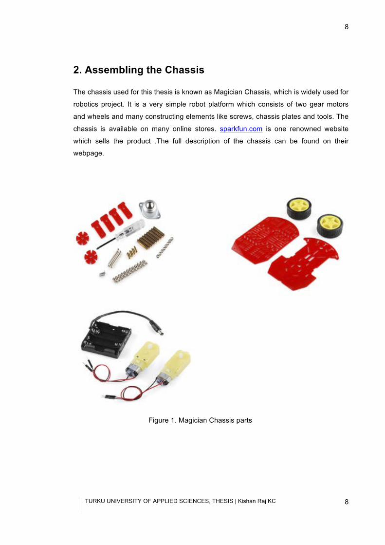
2. Assembling the Chassis
The chassis used for this thesis is known as Magician Chassis, which is widely used for
robotics project. It is a very simple robot platform which consists of two gear motors
and wheels and many constructing elements like screws, chassis plates and tools. The
chassis is available on many online stores. sparkfun.com is one renowned website
which sells the product .The full description of the chassis can be found on their
webpage.
Figure 1. Magician Chassis parts
TURKU UNIVERSITY OF APPLIED SCIENCES, THESIS | Kishan Raj KC
9
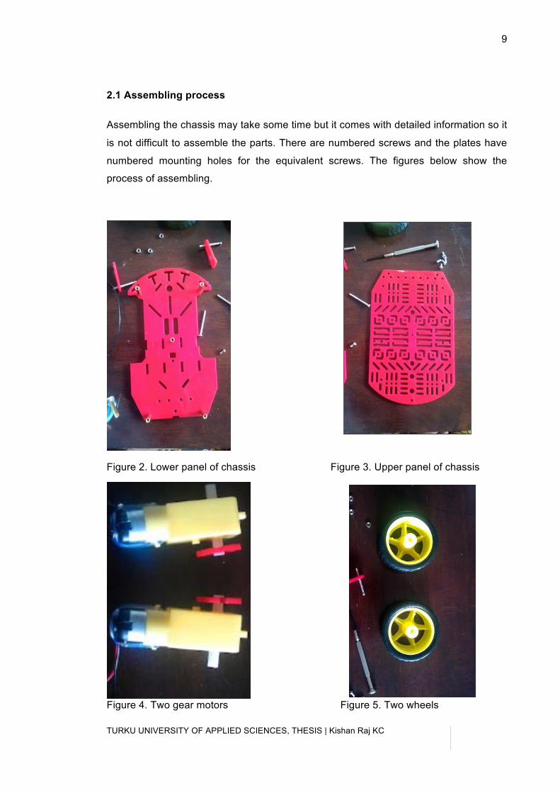
2.1 Assembling process
Assembling the chassis may take some time but it comes with detailed information so it
is not difficult to assemble the parts. There are numbered screws and the plates have
numbered mounting holes for the equivalent screws. The figures below show the
process of assembling.
Figure 2. Lower panel of chassis Figure 3. Upper panel of chassis
Figure 4. Two gear motors Figure 5. Two wheels
TURKU UNIVERSITY OF APPLIED SCIENCES, THESIS | Kishan Raj KC
10
10
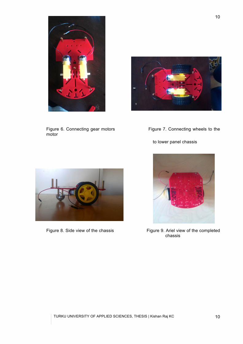
Figure 6. Connecting gear motors Figure 7. Connecting wheels to the motor
to lower panel chassis
Figure 8. Side view of the chassis Figure 9. Ariel view of the completed chassis
TURKU UNIVERSITY OF APPLIED SCIENCES, THESIS | Kishan Raj KC
11
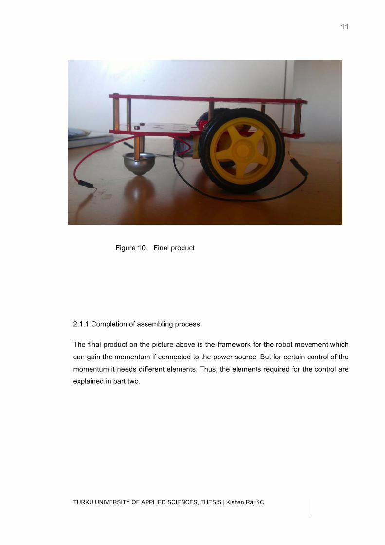
Figure 10. Final product
2.1.1 Completion of assembling process
The final product on the picture above is the framework for the robot movement which
can gain the momentum if connected to the power source. But for certain control of the
momentum it needs different elements. Thus, the elements required for the control are
explained in part two.
TURKU UNIVERSITY OF APPLIED SCIENCES, THESIS | Kishan Raj KC
12
12
3 Arduino, Ardumoto, Bluetooth modem and Circuit Design This chapter of the thesis concentrates on the use of Arduino as the brain of the project
which controls the action of the robot through signals sent from it. Ardumoto is a motor
driver shield which can control two DC motors and drive up to 2 A per channel. A
Bluetooth modem is a medium that enables Arduino to connect to the android device or
smartphone. Thus, the modem is the bridge for the commands sent from a smartphone
to the Arduino. In addition, to power up the gear motors with appropriate signals, there
is a need for a circuit to be designed.
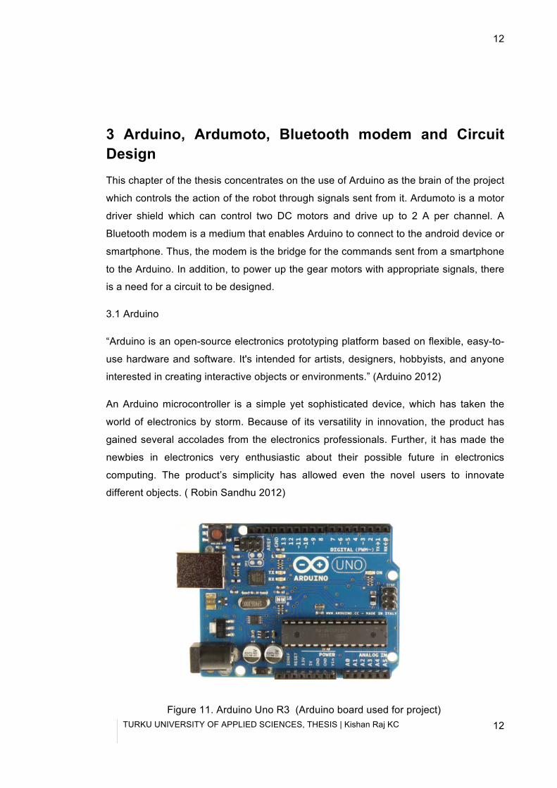
3.1 Arduino
“Arduino is an open-source electronics prototyping platform based on flexible, easy-to-
use hardware and software. It's intended for artists, designers, hobbyists, and anyone
interested in creating interactive objects or environments.” (Arduino 2012)
An Arduino microcontroller is a simple yet sophisticated device, which has taken the
world of electronics by storm. Because of its versatility in innovation, the product has
gained several accolades from the electronics professionals. Further, it has made the
newbies in electronics very enthusiastic about their possible future in electronics
computing. The product’s simplicity has allowed even the novel users to innovate
different objects. ( Robin Sandhu 2012)
Figure 11. Arduino Uno R3 (Arduino board used for project)
TURKU UNIVERSITY OF APPLIED SCIENCES, THESIS | Kishan Raj KC
13
3.1.1 Arduino History
The project Arduino first began in 2005 at Interaction Design Institute Ivrea (IDII) but
the dawn of Arduino began in year 2002 when Massimo Banzi (Massimo Banzi 2012)
co-founder of Arduino was appointed as an associate professor to teach the students
of IDII to promote modern ways of interactive design. (David Kushner 2011)
Banzi wanted to offer his students something modern and inexpensive so everybody
could carry their works without many obstacles. By then, the most used tool in the
market was BASIC Stamp (Parallax 2012), which was expensive. So as an alternative
Banzi wanted to develop something better. Banzi was also involved in processing
(Processing 2012), the processing language. So with the help of a Colombian student
Hernando Barragán (Barragan Studio 2012) who was working on a wiring (Wiring
2012) platform, they tried to make processing for hardware and make it simpler and
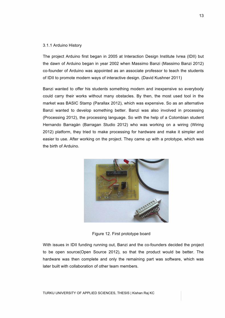
easier to use. After working on the project. They came up with a prototype, which was
the birth of Arduino.
Figure 12. First prototype board
With issues in IDII funding running out, Banzi and the co-founders decided the project
to be open source(Open Source 2012), so that the product would be better. The
hardware was then complete and only the remaining part was software, which was
later built with collaboration of other team members.
TURKU UNIVERSITY OF APPLIED SCIENCES, THESIS | Kishan Raj KC
14
14
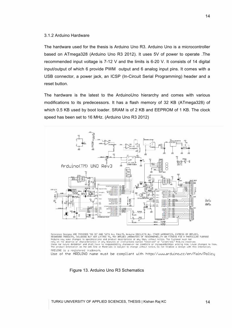
3.1.2 Arduino Hardware
The hardware used for the thesis is Arduino Uno R3. Arduino Uno is a microcontroller
based on ATmega328 (Arduino Uno R3 2012). It uses 5V of power to operate .The
recommended input voltage is 7-12 V and the limits is 6-20 V. It consists of 14 digital
input/output of which 6 provide PWM output and 6 analog input pins. It comes with a
USB connector, a power jack, an ICSP (In-Circuit Serial Programming) header and a
reset button.
The hardware is the latest to the ArduinoUno hierarchy and comes with various
modifications to its predecessors. It has a flash memory of 32 KB (ATmega328) of
which 0.5 KB used by boot loader. SRAM is of 2 KB and EEPROM of 1 KB. The clock
speed has been set to 16 MHz. (Arduino Uno R3 2012)
Figure 13. Arduino Uno R3 Schematics
TURKU UNIVERSITY OF APPLIED SCIENCES, THESIS | Kishan Raj KC
15
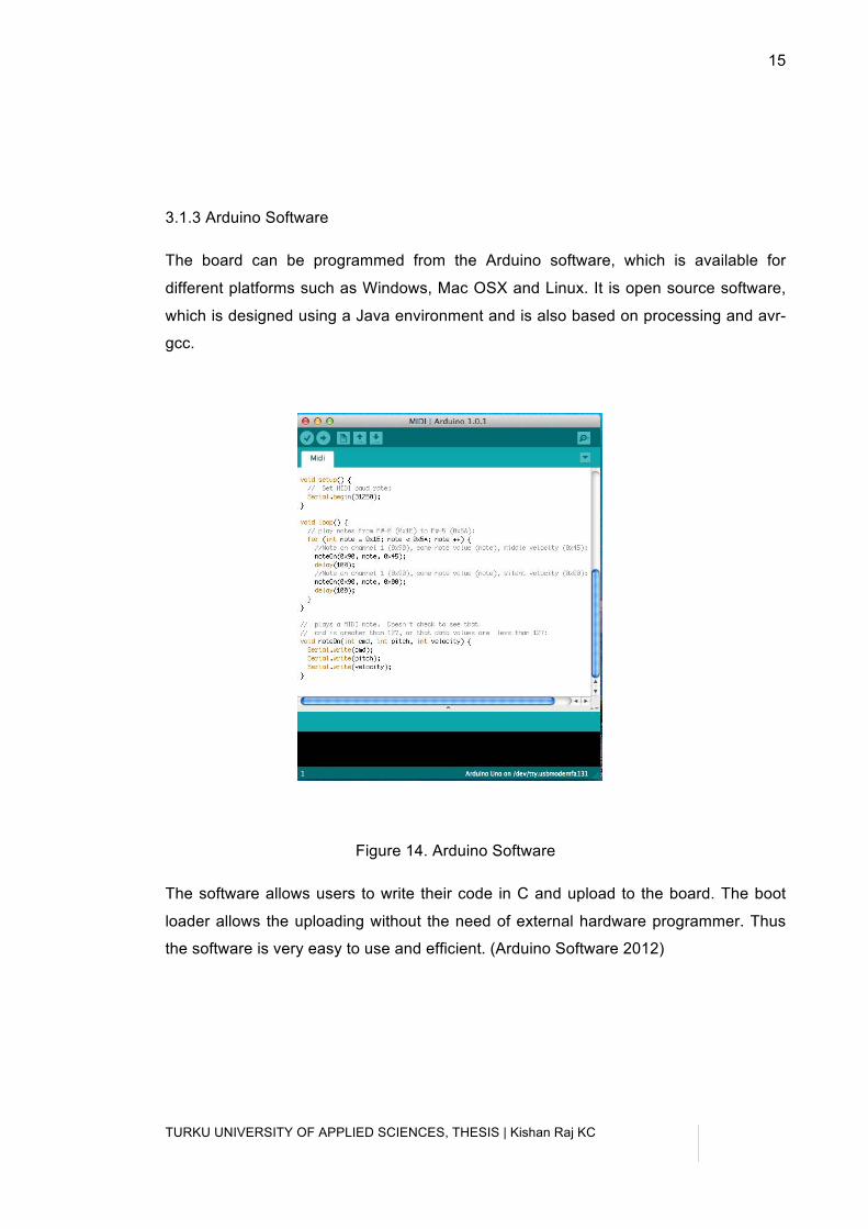
3.1.3 Arduino Software
The board can be programmed from the Arduino software, which is available for
different platforms such as Windows, Mac OSX and Linux. It is open source software,
which is designed using a Java environment and is also based on processing and avr-
gcc.
Figure 14. Arduino Software
The software allows users to write their code in C and upload to the board. The boot
loader allows the uploading without the need of external hardware programmer. Thus
the software is very easy to use and efficient. (Arduino Software 2012)
TURKU UNIVERSITY OF APPLIED SCIENCES, THESIS | Kishan Raj KC
16
16
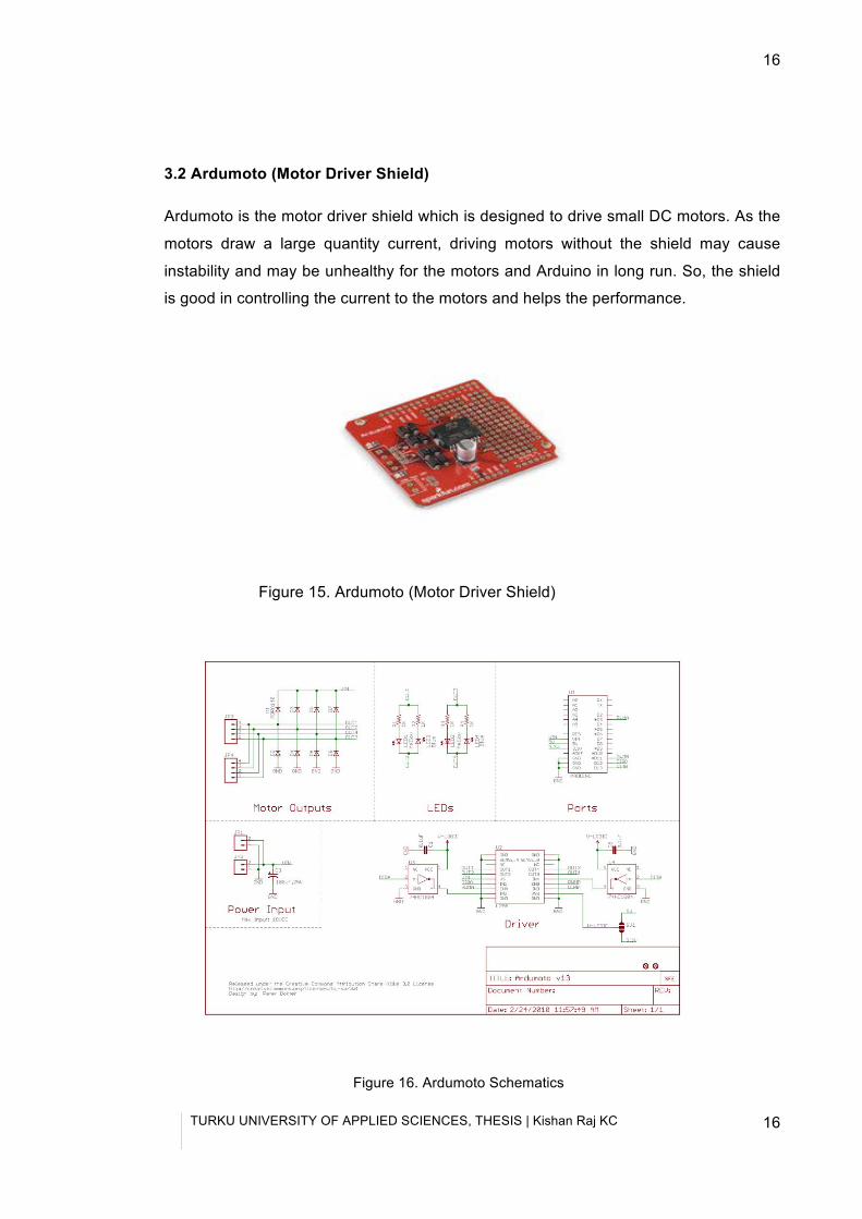
3.2 Ardumoto (Motor Driver Shield)
Ardumoto is the motor driver shield which is designed to drive small DC motors. As the
motors draw a large quantity current, driving motors without the shield may cause
instability and may be unhealthy for the motors and Arduino in long run. So, the shield
is good in controlling the current to the motors and helps the performance.
Figure 15. Ardumoto (Motor Driver Shield)
Figure 16. Ardumoto Schematics
TURKU UNIVERSITY OF APPLIED SCIENCES, THESIS | Kishan Raj KC
17
3.3 BlueSMiRF (Bluetooth modem)
Bluetooth is a technology developed to eradicate the need of wires to communicate
among different devices. Bluetooth is a wireless technology which has been a major
innovation in world of technology as it has made the communication robust, easy, and
low cost and energy. Most of the devices today have adopted this technology, thus
resulting in various innovations daily. (Bluetooth 2012)
This technology stands out among the top in front of other wireless technology because
it accedes the developers both link layer and application layer definitions allowing the
support of both data and voice communications. It is a technology operating at
industrial, scientific and medical (ISM) unlicensed band of 2.4 to 2.485 GHz. It uses
spread spectrum, frequency hopping and full duplex signal at a nominal rate of 1600
hops/sec. Bluetooth can operate at the range between 10 to 100 m. (Bluetooth 2012)
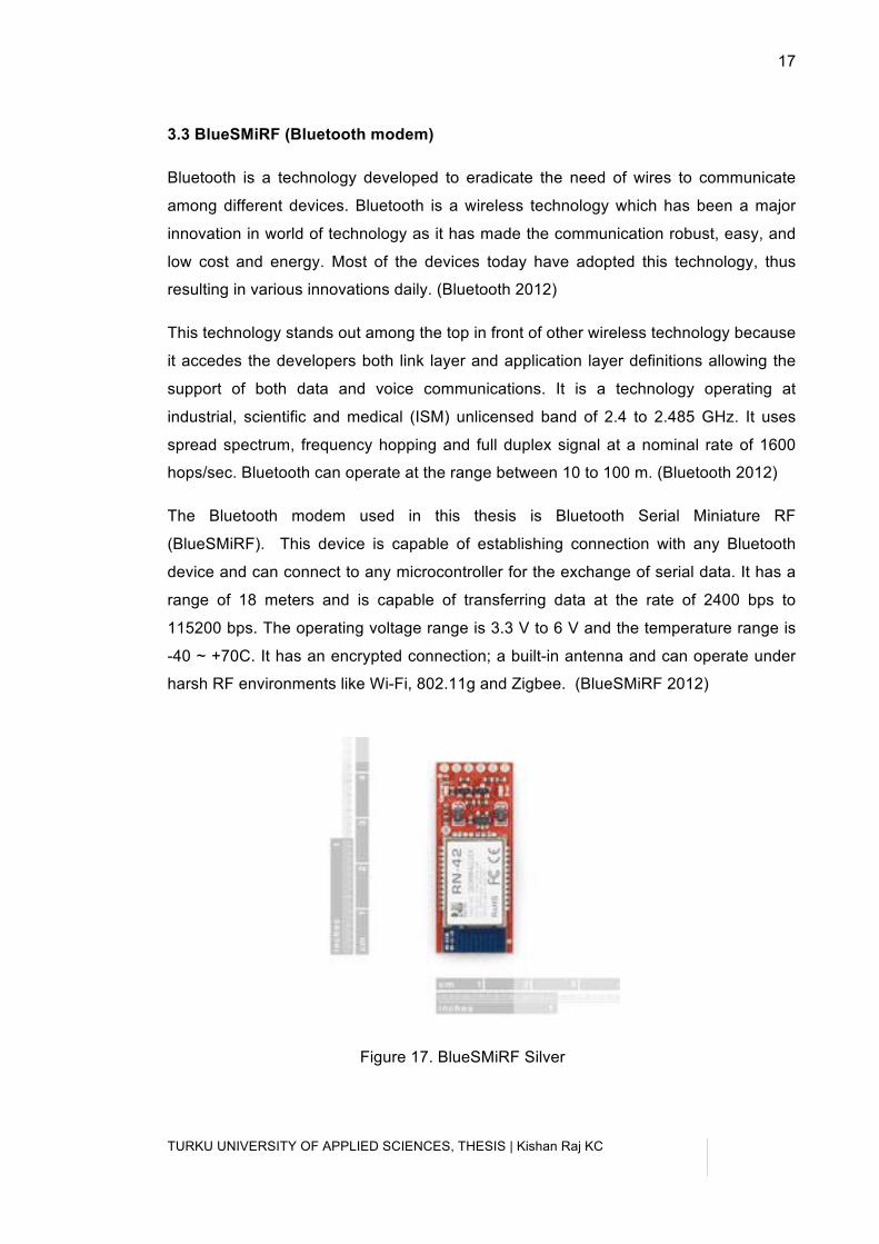
The Bluetooth modem used in this thesis is Bluetooth Serial Miniature RF
(BlueSMiRF). This device is capable of establishing connection with any Bluetooth
device and can connect to any microcontroller for the exchange of serial data. It has a
range of 18 meters and is capable of transferring data at the rate of 2400 bps to
115200 bps. The operating voltage range is 3.3 V to 6 V and the temperature range is
-40 ~ +70C. It has an encrypted connection; a built-in antenna and can operate under
harsh RF environments like Wi-Fi, 802.11g and Zigbee. (BlueSMiRF 2012)
Figure 17. BlueSMiRF Silver
TURKU UNIVERSITY OF APPLIED SCIENCES, THESIS | Kishan Raj KC
18
18
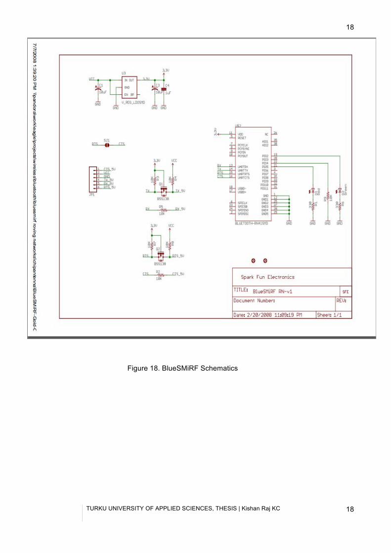
Figure 18. BlueSMiRF Schematics
TURKU UNIVERSITY OF APPLIED SCIENCES, THESIS | Kishan Raj KC
19
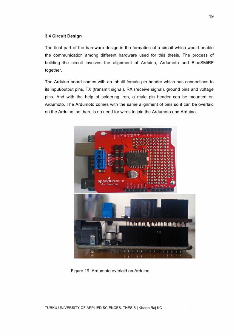
3.4 Circuit Design
The final part of the hardware design is the formation of a circuit which would enable
the communication among different hardware used for this thesis. The process of
building the circuit involves the alignment of Arduino, Ardumoto and BlueSMiRF
together.
The Arduino board comes with an inbuilt female pin header which has connections to
its input/output pins, TX (transmit signal), RX (receive signal), ground pins and voltage
pins. And with the help of soldering iron, a male pin header can be mounted on
Ardumoto. The Ardumoto comes with the same alignment of pins so it can be overlaid
on the Arduino, so there is no need for wires to join the Ardumoto and Arduino.
Figure 19. Ardumoto overlaid on Arduino
TURKU UNIVERSITY OF APPLIED SCIENCES, THESIS | Kishan Raj KC
20
20
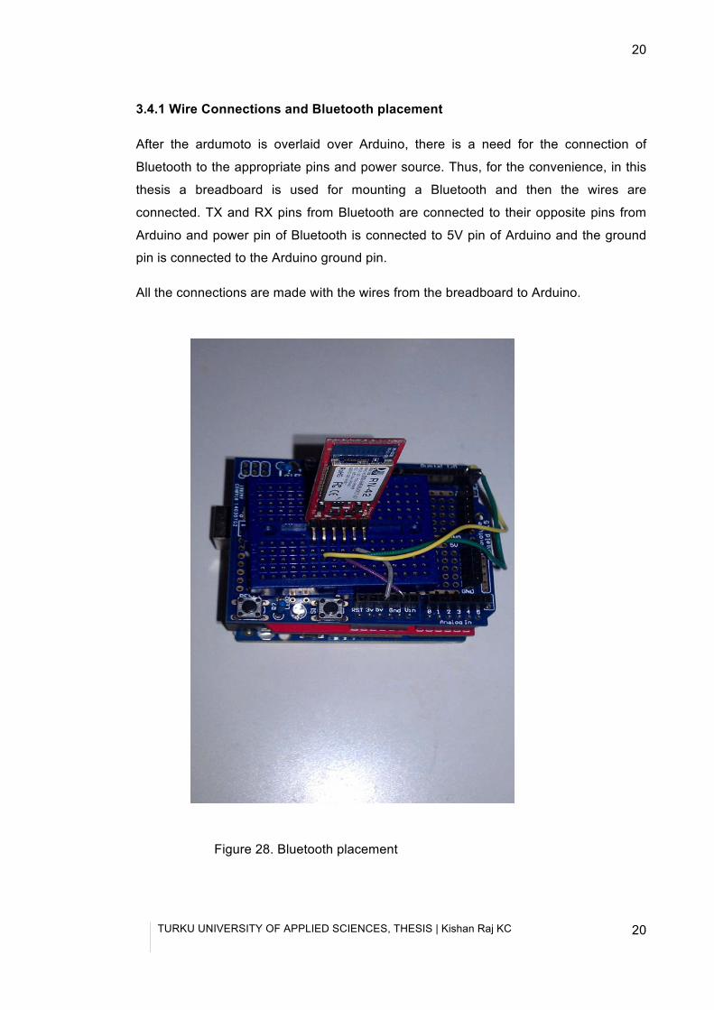
3.4.1 Wire Connections and Bluetooth placement
After the ardumoto is overlaid over Arduino, there is a need for the connection of
Bluetooth to the appropriate pins and power source. Thus, for the convenience, in this
thesis a breadboard is used for mounting a Bluetooth and then the wires are
connected. TX and RX pins from Bluetooth are connected to their opposite pins from
Arduino and power pin of Bluetooth is connected to 5V pin of Arduino and the ground
pin is connected to the Arduino ground pin.
All the connections are made with the wires from the breadboard to Arduino.
Figure 28. Bluetooth placement
TURKU UNIVERSITY OF APPLIED SCIENCES, THESIS | Kishan Raj KC
21
4. SOFTWARE DESING (ANDROID APP DESING)
The software or the android application for the thesis was designed using a very
innovative product initially provided by Google but now under the maintenance of the
Massachusetts Institute of Technology (MIT) known as MIT app Inventor (App Inventor
2012). The software was previously called Google App Inventor and was released
publicly on December 15,2010 only to be terminated one year later on December
31,2011. However, the product is now under MIT Centre for mobile learning and by the
name MIT App Inventor. (Larry 2010)
Technology is all about efficiency. As technology has advanced things have become
simpler. So application development is no longer limited to the fierce programmers,
now users with very limited programming knowledge are able to develop applications.
Thus, the product is a simple yet effective way in Android application development. The
App Inventor allows its users to develop different kinds of Android apps just over a web
browser. A user needs a Google account to get started with and the app inventor’s
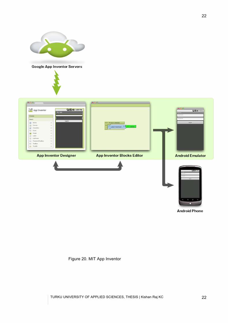
servers stores and keep tracks of all the work user uploads. The application building
process in App Inventor involves three aspects:
(i) App inventor designer,
(ii) App Inventor Blocks editor, and
(iii) An emulator or Android Phone.
The set-up process for the software is very easy. The system requirements are very
basic and it is compatible with Mac OSX, Windows and Linux Operating systems.
Browsers required for the software are Mozilla Firefox 3.6 or higher, Apple Safari 5.0 or
higher, Google Chrome 4.0 or higher and Microsoft Internet Explorer 7.0 or higher.
(App Inventor 2012)
TURKU UNIVERSITY OF APPLIED SCIENCES, THESIS | Kishan Raj KC
22
22
Figure 20. MIT App Inventor
TURKU UNIVERSITY OF APPLIED SCIENCES, THESIS | Kishan Raj KC
23
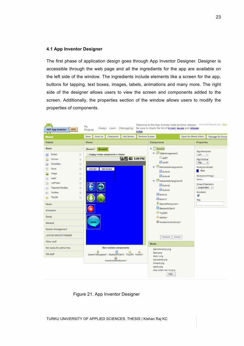
4.1 App Inventor Designer
The first phase of application design goes through App Inventor Designer. Designer is
accessible through the web page and all the ingredients for the app are available on
the left side of the window. The ingredients include elements like a screen for the app,
buttons for tapping, text boxes, images, labels, animations and many more. The right
side of the designer allows users to view the screen and components added to the
screen. Additionally, the properties section of the window allows users to modify the
properties of components.
Figure 21. App Inventor Designer
TURKU UNIVERSITY OF APPLIED SCIENCES, THESIS | Kishan Raj KC
24
24
Adding the components to the screen is a simple drag-and-drop process. Then the
alignment of the components can be managed through alignment options on the left
side of the window. The figure above shows the features added to the application for
this thesis. Several non-visible components are also added to the screen, which are
explored later in the blocks editor.
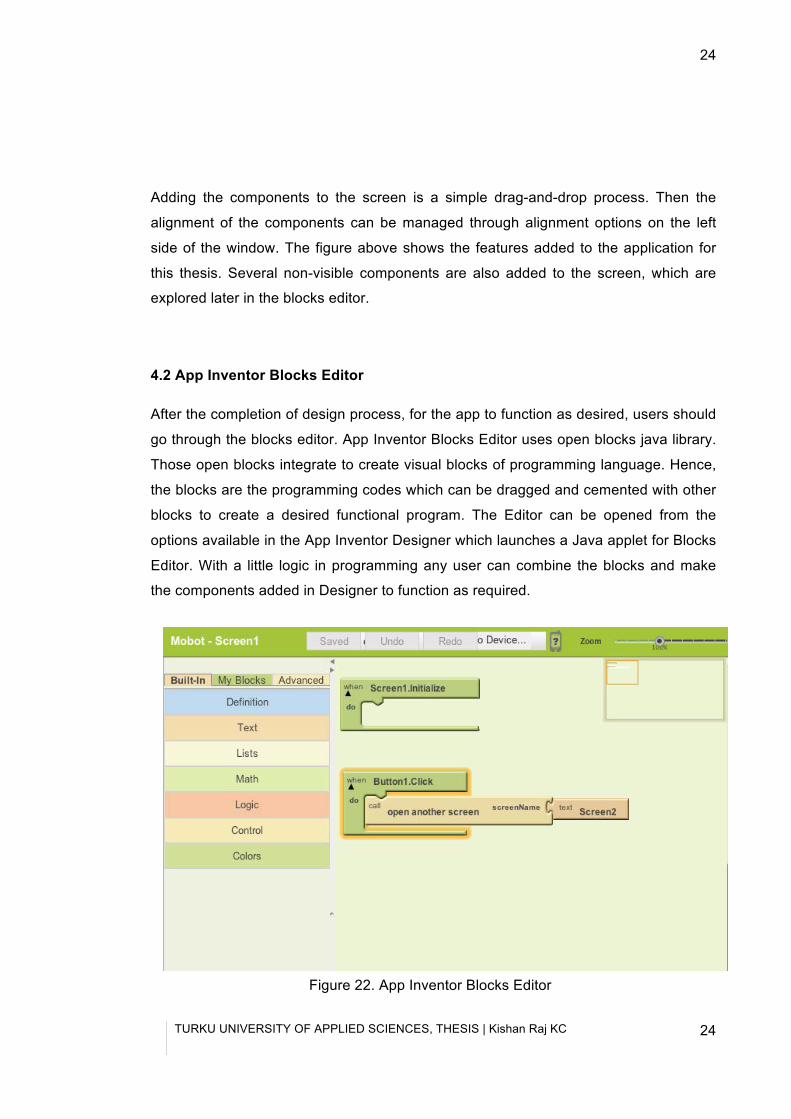
4.2 App Inventor Blocks Editor
After the completion of design process, for the app to function as desired, users should
go through the blocks editor. App Inventor Blocks Editor uses open blocks java library.
Those open blocks integrate to create visual blocks of programming language. Hence,
the blocks are the programming codes which can be dragged and cemented with other
blocks to create a desired functional program. The Editor can be opened from the
options available in the App Inventor Designer which launches a Java applet for Blocks
Editor. With a little logic in programming any user can combine the blocks and make
the components added in Designer to function as required.
Figure 22. App Inventor Blocks Editor
TURKU UNIVERSITY OF APPLIED SCIENCES, THESIS | Kishan Raj KC
25
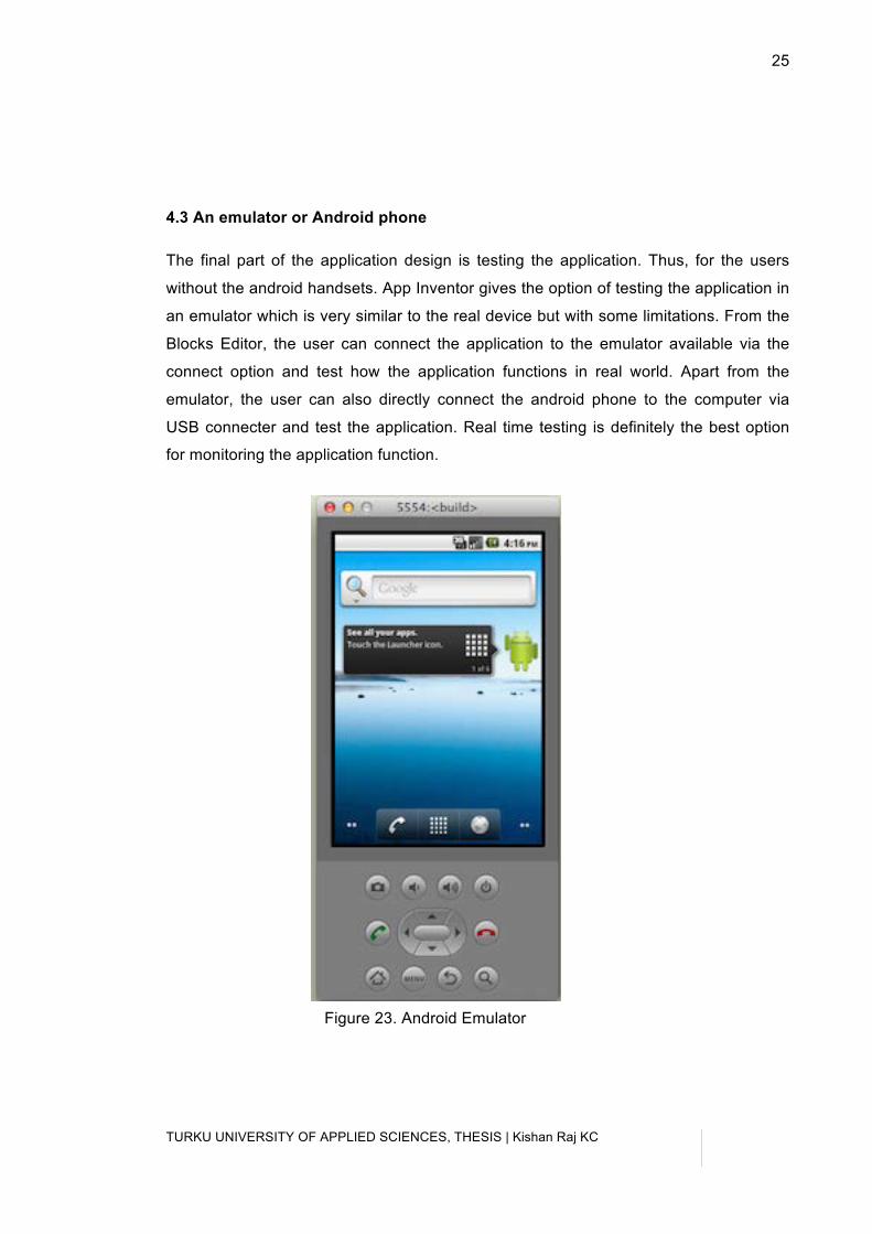
4.3 An emulator or Android phone
The final part of the application design is testing the application. Thus, for the users
without the android handsets. App Inventor gives the option of testing the application in
an emulator which is very similar to the real device but with some limitations. From the
Blocks Editor, the user can connect the application to the emulator available via the
connect option and test how the application functions in real world. Apart from the
emulator, the user can also directly connect the android phone to the computer via
USB connecter and test the application. Real time testing is definitely the best option
for monitoring the application function.
Figure 23. Android Emulator
TURKU UNIVERSITY OF APPLIED SCIENCES, THESIS | Kishan Raj KC
26
26
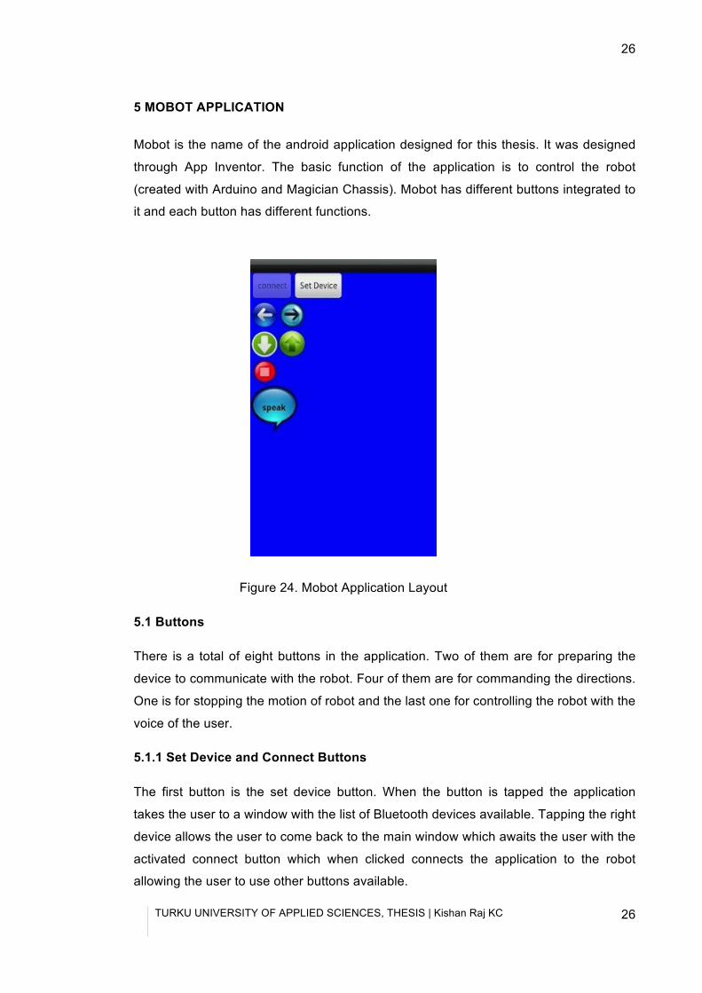
5 MOBOT APPLICATION
Mobot is the name of the android application designed for this thesis. It was designed
through App Inventor. The basic function of the application is to control the robot
(created with Arduino and Magician Chassis). Mobot has different buttons integrated to
it and each button has different functions.
Figure 24. Mobot Application Layout
5.1 Buttons
There is a total of eight buttons in the application. Two of them are for preparing the
device to communicate with the robot. Four of them are for commanding the directions.
One is for stopping the motion of robot and the last one for controlling the robot with the
voice of the user.
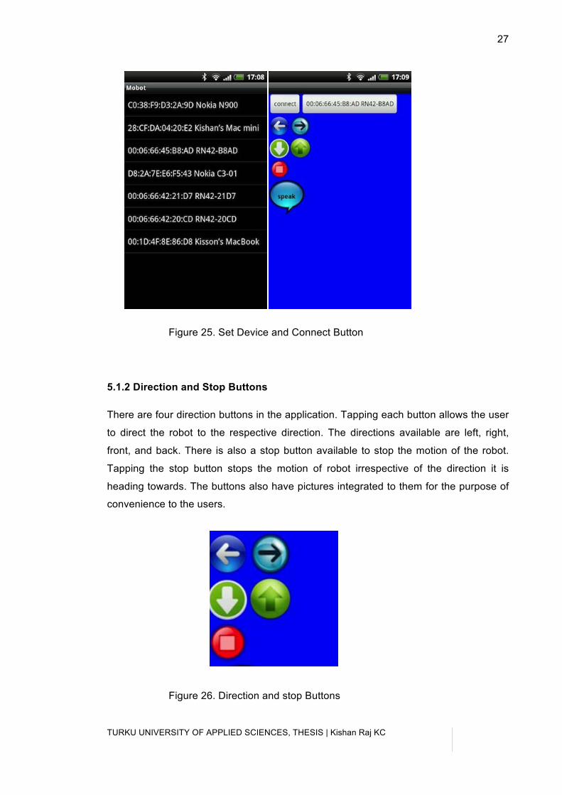
5.1.1 Set Device and Connect Buttons
The first button is the set device button. When the button is tapped the application
takes the user to a window with the list of Bluetooth devices available. Tapping the right
device allows the user to come back to the main window which awaits the user with the
activated connect button which when clicked connects the application to the robot
allowing the user to use other buttons available.
TURKU UNIVERSITY OF APPLIED SCIENCES, THESIS | Kishan Raj KC
27
Figure 25. Set Device and Connect Button
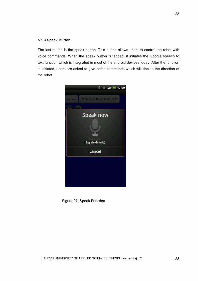
5.1.2 Direction and Stop Buttons
There are four direction buttons in the application. Tapping each button allows the user
to direct the robot to the respective direction. The directions available are left, right,
front, and back. There is also a stop button available to stop the motion of the robot.
Tapping the stop button stops the motion of robot irrespective of the direction it is
heading towards. The buttons also have pictures integrated to them for the purpose of
convenience to the users.
Figure 26. Direction and stop Buttons
TURKU UNIVERSITY OF APPLIED SCIENCES, THESIS | Kishan Raj KC
28
28
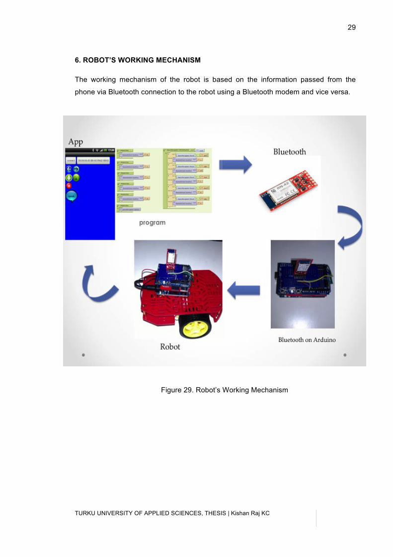
5.1.3 Speak Button
The last button is the speak button. This button allows users to control the robot with
voice commands. When the speak button is tapped, it initiates the Google speech to
text function which is integrated in most of the android devices today. After the function
is initiated, users are asked to give some commands which will decide the direction of
the robot.
Figure 27. Speak Function
TURKU UNIVERSITY OF APPLIED SCIENCES, THESIS | Kishan Raj KC
29
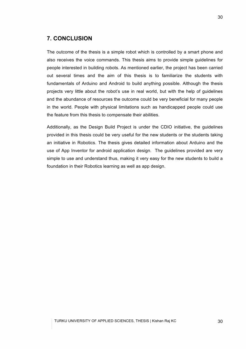
6. ROBOT’S WORKING MECHANISM
The working mechanism of the robot is based on the information passed from the
phone via Bluetooth connection to the robot using a Bluetooth modem and vice versa.
Figure 29. Robot’s Working Mechanism
TURKU UNIVERSITY OF APPLIED SCIENCES, THESIS | Kishan Raj KC
30
30
7. CONCLUSION
The outcome of the thesis is a simple robot which is controlled by a smart phone and
also receives the voice commands. This thesis aims to provide simple guidelines for
people interested in building robots. As mentioned earlier, the project has been carried
out several times and the aim of this thesis is to familiarize the students with
fundamentals of Arduino and Android to build anything possible. Although the thesis
projects very little about the robot’s use in real world, but with the help of guidelines
and the abundance of resources the outcome could be very beneficial for many people
in the world. People with physical limitations such as handicapped people could use
the feature from this thesis to compensate their abilities.
Additionally, as the Design Build Project is under the CDIO initiative, the guidelines
provided in this thesis could be very useful for the new students or the students taking
an initiative in Robotics. The thesis gives detailed information about Arduino and the
use of App Inventor for android application design. The guidelines provided are very
simple to use and understand thus, making it very easy for the new students to build a
foundation in their Robotics learning as well as app design.
TURKU UNIVERSITY OF APPLIED SCIENCES, THESIS | Kishan Raj KC
31
References
2005 arduino (2012). Roadmap. Retrieved September 6,2012, from
http://arduino.cc/en/Main/ArduinoRoadmap
App Inventor. (2012). MIT App Inventor. Retrieved September 19, 2012, from
http://appinventor.mit.edu/
Arduino. (2012) Arduino. Retrieved September 6, 2012, from
http://arduino.cc/en/
Magician chassis parts (2012). Magician chassis. Retrieved September 6, 2012, from https://www.sparkfun.com/products/10825?
Arduino Uno R3 (2012). Arduino. Retrieved September 6, 2012, from
http://arduino.cc/en/Main/ArduinoBoardUno
Ardumoto (2012). Ardumoto-Motor Driver Shield. Retrieved September 11, 2012, from
https://www.sparkfun.com/products/9815
Arduino Software (2012). Software Download. Retrieved September 11, 2012, from
http://arduino.cc/en/Main/Software
Basic Stamp (2012). Parallax. Retrieved September 6, 2012, from
http://www.parallax.com/tabid/295/Default.aspx
BlueSMiRF (2012). Bluetooth Modem- BlueSMiRF Silver. Retrieved September 12, 2012, from
https://www.sparkfun.com/products/10269
Bluetooth (2012). Bluetooth Technology. Retrieved September 12, 2012, from
http://www.bluetooth.com/Pages/Basics.aspx
CDIO (2012) CDIO Initiative. Retrieved November 9, 2012, from
http://www.cdio.org/
David Kushner (October 2011). Making of Arduino. Retrieved September 6, 2012, from
http://spectrum.ieee.org/geek-life/hands-on/the-making-of-arduino/0
Hernando Barragán (2012). Barraganstudio. Retrieved September 6, 2012, from
TURKU UNIVERSITY OF APPLIED SCIENCES, THESIS | Kishan Raj KC
32
32
http://barraganstudio.com/b/?page_id=2
Larry Hardesty (August 19, 2010). "The MIT roots of Google's new software”. Retrieved September 19, 2012, from
http://web.mit.edu/newsoffice/2010/android-abelson-0819.html
Massimo Banzi (2012). About. Retrieved September 6, 2012, from
http://www.massimobanzi.com/about/
MIT (2012) Massachusetts Institute of Technology. Retrieved September 19,2012, from
http://web.mit.edu/
Open Source (2012). Open source initiative. Retrieved September 6, 2012, from
http://opensource.org/
Processing (2012). Processing. Retrieved September 6, 2012, from
http://processing.org/
PWM (2012). Pulse With Modulation. Retrieved September 6, 2012, from
http://arduino.cc/en/Tutorial/PWM
Robin Sandhu (2012) The Arduino Uno. Retrieved November 9, 2012, from
http://newtech.about.com/od/Devices/a/The-Arduino-Uno.htm
Wiring (2012). Wiring. Retrieved September 6,2012, from
http://wiring.org.co/
TURKU UNIVERSITY OF APPLIED SCIENCES, THESIS | Kishan Raj KC
33
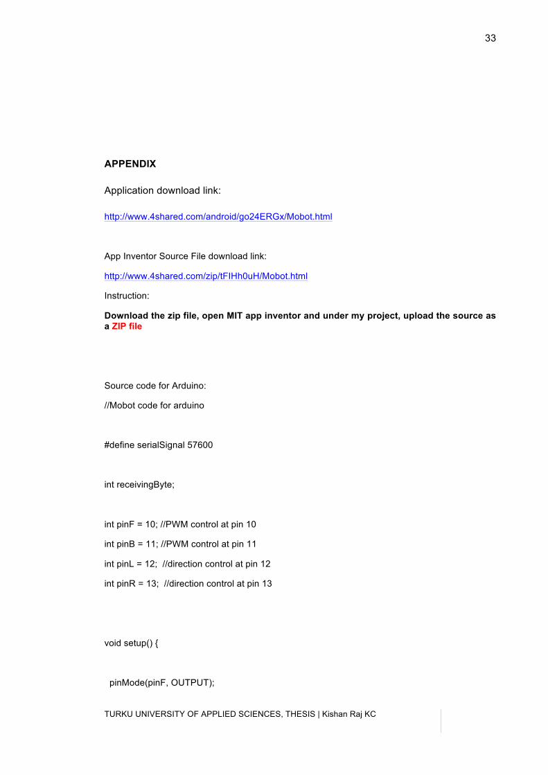
APPENDIX
Application download link:
http://www.4shared.com/android/go24ERGx/Mobot.html
App Inventor Source File download link:
http://www.4shared.com/zip/tFIHh0uH/Mobot.html
Instruction:
Download the zip file, open MIT app inventor and under my project, upload the source as a ZIP file
Source code for Arduino:
//Mobot code for arduino
#define serialSignal 57600
int receivingByte;
int pinF = 10; //PWM control at pin 10
int pinB = 11; //PWM control at pin 11
int pinL = 12; //direction control at pin 12
int pinR = 13; //direction control at pin 13
void setup() {
pinMode(pinF, OUTPUT);
TURKU UNIVERSITY OF APPLIED SCIENCES, THESIS | Kishan Raj KC
34
34
pinMode(pinB, OUTPUT);
pinMode(pinL, OUTPUT);
pinMode(pinR, OUTPUT);
Serial.begin(serialSignal);
}
void loop() {
if(Serial.available()) {
receivingByte = Serial.read();
if (receivingByte == 'B') { //backward
digitalWrite(pinF, HIGH);
digitalWrite(pinB, HIGH);
digitalWrite(pinL, LOW);
digitalWrite(pinR, LOW);
analogWrite(pinF, 255);
analogWrite(pinB, 255);
delay(1000);
}
TURKU UNIVERSITY OF APPLIED SCIENCES, THESIS | Kishan Raj KC
35
if (receivingByte == 'F') { //forward
digitalWrite(pinB, LOW);
digitalWrite(pinF, LOW);
digitalWrite(pinR, HIGH);
digitalWrite(pinL, HIGH);
analogWrite(pinF, 255);
analogWrite(pinB, 255);
delay(1000);
}
if (receivingByte == 'S') { //stop
digitalWrite(pinF, LOW);
digitalWrite(pinB, LOW);
digitalWrite(pinL, LOW);
digitalWrite(pinR, LOW);
}
if (receivingByte == 'R') { //right
digitalWrite(pinL, HIGH);
digitalWrite(pinR, LOW);
digitalWrite(pinB, HIGH);
digitalWrite(pinF, LOW);
delay(1000);
}
TURKU UNIVERSITY OF APPLIED SCIENCES, THESIS | Kishan Raj KC
36
36
if (receivingByte == 'L') { //left
digitalWrite(pinF, HIGH);
digitalWrite(pinB, LOW);
digitalWrite(pinR, HIGH);
digitalWrite(pinL, LOW);
delay(1000);
}
}
}


![LITERATURE REVIEW CO-OPERATIVE MAPPING AND … · a single, controlling robot (The Master robot as mentioned in [18]) or whether each robot is independent and communicates with every](https://img.pdfslide.net/doc/110x75/5f581dce8fea484b3020afd9/literature-review-co-operative-mapping-and-a-single-controlling-robot-the-master.jpg)