Embed Size (px)
Citation preview
The automatic manufacturing processes– the technique of controlling a mobile robot Christian Olsson
2010-10-12
I
Abstract
In today's industry it is of mayor concern to keep the manufacturing processes as effective
and flexible as possible. The usage of robots and automatic technology is a much known
way to achieve the goals of rationalization. The disadvantage lays in the fact that
implementation of robots is usually a very resource consuming task. However, in some
circumstances a solution to this matter may be to simply implement mobile robots instead
of fixed robots.
The task of this project is to successfully control and understand the system of a mobile
robot in a automatic manufacturing process.
Date: 2010-09-15 Author: Christian Olsson Examiner: Mikael Ericsson Advisor: Shanghai University of Engineering Science Mayor: Mechatronic Engineering Main field of study: Engineering Credits: 15 HE credits Keywords: Mobile robot, Motion card, Motoman, Manufacturing process. Publisher: University West, Department of Engineering Science,
S-461 86 Trollhättan, SWEDEN Phone: + 46 520 22 30 00 Fax: + 46 520 22 32 99 Web: www.hv.se
II
Preface
For me to take part in this project would never have been possible if it was not for the
collaboration between University West and Shanghai University of Engineering Science.
My unconditional thanks for giving me this opportunity goes here by to all the staff at both
universities International Office and to all teachers and professors involved.
Christian Olsson
III
Contents
1. Introduction ..............................................................................................................1 1.1 Background ............................................................................................................................ 1 1.2 Purpose ................................................................................................................................... 1 1.1 Limitation ............................................................................................................................... 2
2. Technology .............................................................................................................. 3 2.1 Equipment ................................................................................................................................ 3 2.1 System map ............................................................................................................................... 4 2.1 Profibus I/O ............................................................................................................................ 6
3. Control Theory ......................................................................................................... 7 3.1 Hardware .................................................................................................................................. 7 3.2 Software .................................................................................................................................... 8
4. Programming and testing ....................................................................................... 10
5. Results and conclusions ......................................................................................... 12
6. References ............................................................................................................... 14
Appendix
A. Sample codes ......................................................................................................... 16
B. Mobile robot code .................................................................................................. 18
C. Action diagram ...................................................................................................... 19
D. System sketch ....................................................................................................... 20
E. Dictionary .............................................................................................................. 21
1
1 Introduction
1.1 Background
Today's necessities in the competition of the manufacturing industry are to be flexible to
the always changing market conditions. In the field of automation technology it can at
times seem like it is almost impossible to keep up to date with all the latest development,
and if a company would allow them self to fall back its application of new technology will
be sure to soon find itself incapable of meeting its clients demands. As of result of this
many companies will today show great interest in investing in the modern advanced
systems, very often together with a flexible solution to produce different types of products
all in the same production line. In the flexible systems, often referred as Flexible
Manufacturing Systems (FMS), there are a lot of advantages such as faster production rate,
lower cost/unit, and greater labor productivity. Another important matter today is the level
of automation, the higher level of automation will result in also a higher level of
rationalization the production may reach, and even some applications such as the
Automatic Manufacturing Process (AMP) are not far from completely automated.
In these systems implementing industrial robots is of great importance, however rather
than implementing many robots, in some cases just one mobile robot can successfully do
the job of many fixed robots.
An automated manufacturing process located at the laboratory of Shanghai University of
Engineering Science (SUES) consists of high-technology systems which are to produce
diversified products at an effective rate. One part of this system is a mobile robot located
on a rail between two very essential positions in the production. The first position (often
referred as the home position) is located within reach for a conveyor and a lathe machine,
at this station the mobile robot is suppose to grab items from the conveyor belt and do
some various operations and processing in the lathe machine. Further along the rail there is
a second position, were a CMM (Coordinate-measuring machine) and a milling machine is
reachable for the robot.
1.2 Purpose
The goal of this project is to successfully control and understand the system of a mobile
robot in a given manufacturing process. The task includes both studies on software and
hardware level. The hardware structure includes a two-layered control system, I/Os,
Profibus (Process Field Bus) and Ethernet wiring. The software level consists of computer
communication and the comprehensive Profibus system with an integrated script language
which are to be used for controlling the processes.
2
Secondly, the project also includes related theory regarding different control systems and
there flaws and faults.
1.3 Limitations
The mobile robot has its main objective in the manufacturing process, for the operations
between the lathe and the milling machine, therefore the thesis is limited to this specific
task and nothing else.
In fact, the robot has already been controlled successfully before in a number of
operations. The process is fairly well documented. However there is another rather big
limitation, it’s within the fact that the script language and the documentation are both in
Chinese. Therefore, the translation from Chinese to English is a necessary part of the
whole projects research. See Appendix A for some of the translated documentation and
sample codes.
3
2 Technology
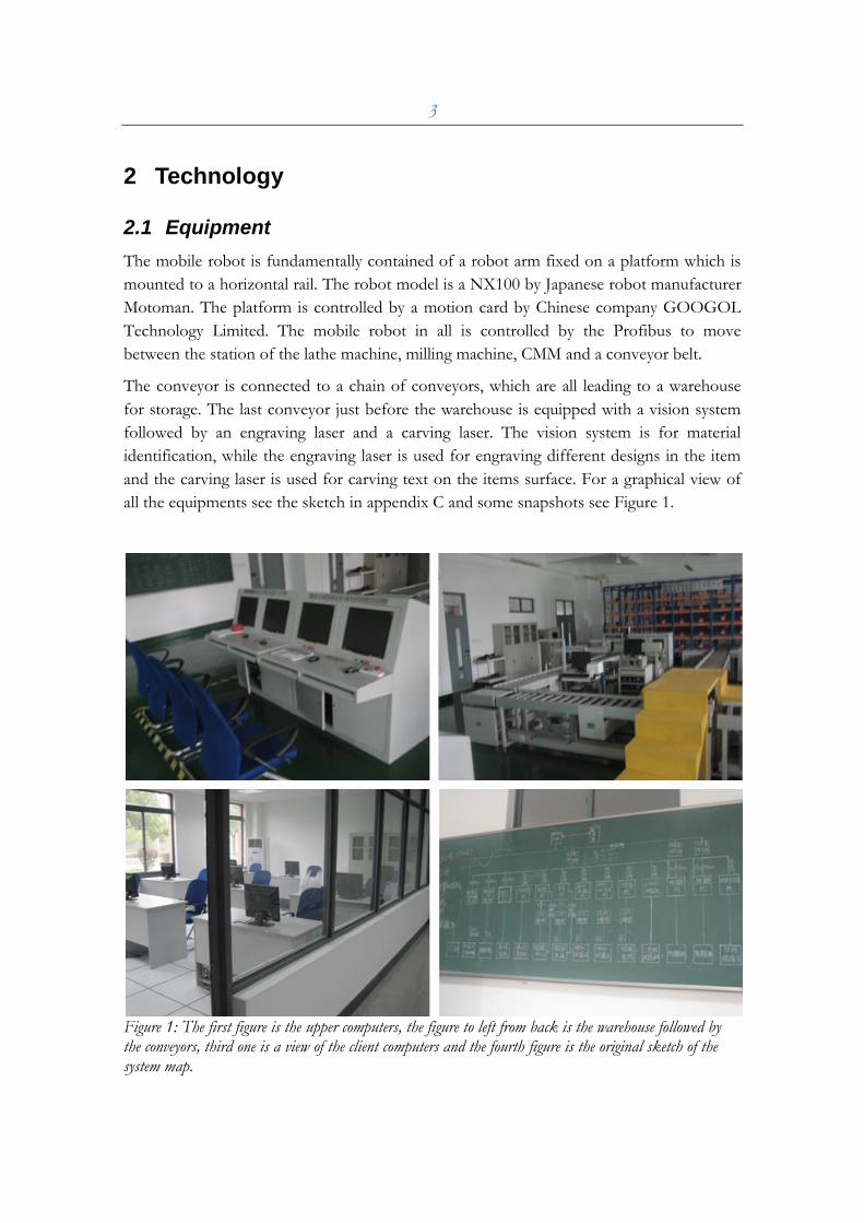
2.1 Equipment
The mobile robot is fundamentally contained of a robot arm fixed on a platform which is
mounted to a horizontal rail. The robot model is a NX100 by Japanese robot manufacturer
Motoman. The platform is controlled by a motion card by Chinese company GOOGOL
Technology Limited. The mobile robot in all is controlled by the Profibus to move
between the station of the lathe machine, milling machine, CMM and a conveyor belt.
The conveyor is connected to a chain of conveyors, which are all leading to a warehouse
for storage. The last conveyor just before the warehouse is equipped with a vision system
followed by an engraving laser and a carving laser. The vision system is for material
identification, while the engraving laser is used for engraving different designs in the item
and the carving laser is used for carving text on the items surface. For a graphical view of
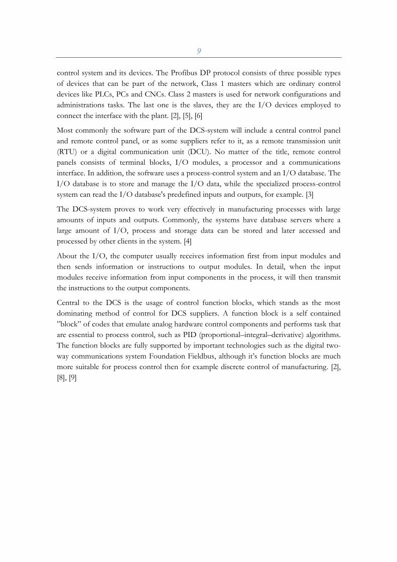
all the equipments see the sketch in appendix C and some snapshots see Figure 1.
Figure 1: The first figure is the upper computers, the figure to left from back is the warehouse followed by the conveyors, third one is a view of the client computers and the fourth figure is the original sketch of the system map.
4
Most of the components and devices such as the conveyors and lasers are connected to the
Profibus I/O box and working directly under the Profibus interface. See Figure 1 for a
detailed list regarding the Profibus I/O's.
The sub-computers of the system are another important part of the equipment. They are
used to program the Profibus scripts. The programming language is completely integrated
in the Profibus software, which means the scripts must be programmed locally in the
computers in the laboratory.
Another type of computer used in this manufacturing process is the upper computer, were debugged and readymade scripts can be executed and tested on the real system.
The upper computer also holds the important task of monitoring and managing the sub-
systems and processes which are working beneath it.
One of the systems that are directly controlled by the upper computers is the warehouse.
The system of the warehouse consists of sub-systems, such as the Production Management
System (PMS) for production and order management, and Manufacturing Execution
System (MES) for managing the production line's work-in-processes. For a map of the
computers and the system in whole, see Figure 1.
5
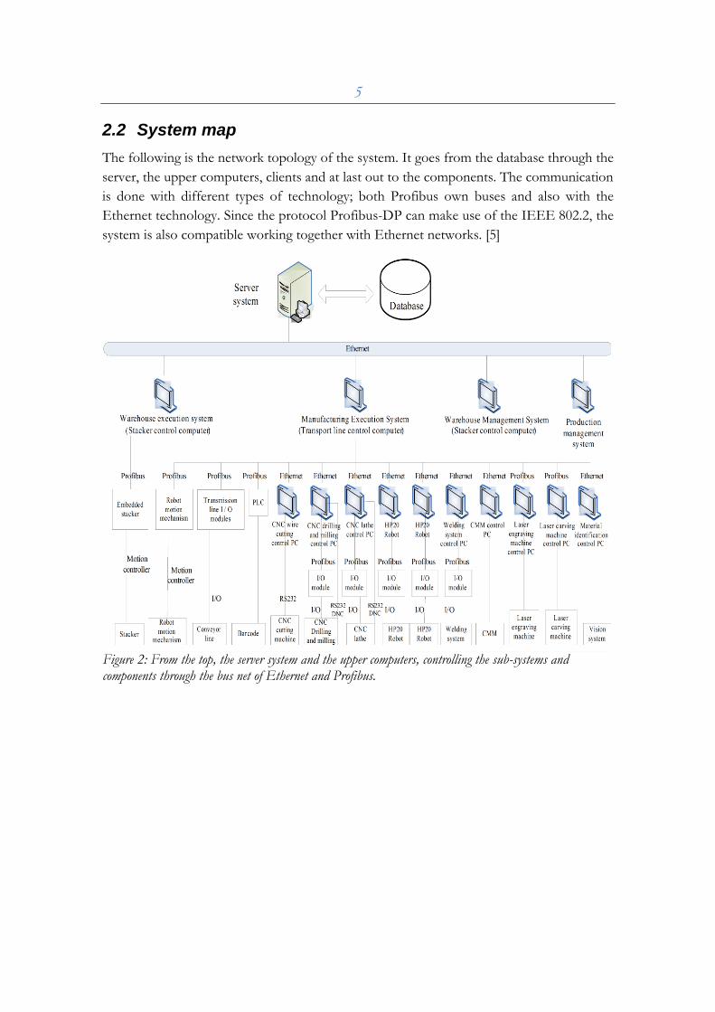
2.2 System map
The following is the network topology of the system. It goes from the database through the
server, the upper computers, clients and at last out to the components. The communication
is done with different types of technology; both Profibus own buses and also with the
Ethernet technology. Since the protocol Profibus-DP can make use of the IEEE 802.2, the
system is also compatible working together with Ethernet networks. [5]
Figure 2: From the top, the server system and the upper computers, controlling the sub-systems and components through the bus net of Ethernet and Profibus.
6
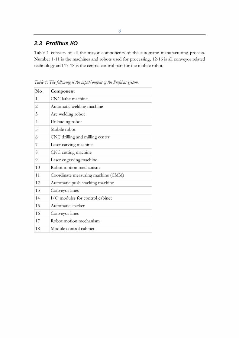
2.3 Profibus I/O
Table 1 consists of all the mayor components of the automatic manufacturing process.
Number 1-11 is the machines and robots used for processing, 12-16 is all conveyor related
technology and 17-18 is the central control part for the mobile robot.
Table 1: The following is the input/output of the Profibus system.
No Component
1 CNC lathe machine
2 Automatic welding machine
3 Arc welding robot
4 Unloading robot
5 Mobile robot
6 CNC drilling and milling center
7 Laser carving machine
8 CNC cutting machine
9 Laser engraving machine
10 Robot motion mechanism
11 Coordinate measuring machine (CMM)
12 Automatic push stacking machine
13 Conveyor lines
14 I/O modules for control cabinet
15 Automatic stacker
16 Conveyor lines
17 Robot motion mechanism
18 Module control cabinet
7
3 Control Theory
3.1 Hardware
The manufacturing process is controlled by a distributed control system (DCS) which is a
system divided into a two-layer system communicated by TCP/IP over Ethernet. It has a
monitor computer which is designed to supervise the process while sub-computers
simultaneously control the I/O devices by the fieldbus called Profibus.
DCS is a very wide term used in a variety of manufacturing industries, to monitor and
control distributed equipment. It can be designed as open loop or closed or even both.
These systems consist of a number of controllers connected to a field bus i.e. in this case
the Profibus. It mostly serves to control, large scale system like production lines in
factories, airplane, oil terminals, airport earth services and unified power systems. [1], [13]
A distributed communication system works as a peer-to-peer network where the entire
system is connected for communication and monitoring. This can cause some difficulties
during the designing, debugging and testing since the system is in need of a quite
comprehensives global vision at design time. [4]
Although, what’s much more important is the fact that it will give a big advantage over
other control systems. For example, if a component or a sub-system is malfunctioning the
maintaining system can still operate since the system is only losing a branch of a possible
many. Especially, it has advantages over the centralized control system where everything is
trusted to be controlled directly by only one layer, (centralized just like a brain) while in a
distributed control system the components' sub-system is all in different layers. What’s
more, since the sensors/actuators are shared by all the processing nodes and still controls a
part of the control process, it will eliminate the need for any kind of sensor/actuator
redundancy. Redundancy may only be needed to improve the reliability of the whole
control system. [4], [10]
Using a centralized control system can involve some various problems. First of all the
point-to-point connection principle may result in very complex wiring since each and every
sensor/actuators need their own cables. Another problem of this great amount of cables is
difficulties in maintenance and documentation of the communication system. Secondly, the
closed nature of a centralized architecture generally results in difficulties when upgrading
the system to meet new requirements. Nowadays, there are actually still industrial plants
with centralized configurations out there. For projects with more simple applications
contained by limited numbers of sensors/actuators this type of solution can quite work. [4],
[10], [12]
8
Distributed control systems dissent in terms of usage and scale. Smaller scale may consist
of only a single programmable logic controller (PLC) connected to an upper computer
Bigger, more advanced DCS setups are also often PLC-based, but usually uses computers
for subsystems that provides both I/O and computer communication. Also, the control
system may work under one or several workstations (usually computers) and can be
configured at the workstation or by an external computer connected to a network. [3], [4]
When talking about the hardware aspect of a control system the communication between
the devices is a main issue. In a control system with a fieldbus an operator can easily
communicate from his own workstation with all the systems other devices, making it
possible to keep the workstation detach from the rest of the hardware architecture. In the
end it will make a lot simpler topology and also make the development of the various
components more independent. When the situation demands it the components can be
reprogrammed through the fieldbus to adapt them to new functions by downloading new
configuration software. The fieldbus permits the excessively large variety of I/O cards
which is required for specialized control systems to be reduced since the information flow
within sensors and actuators is now in digital. A standard interface with the fieldbus will
succesfully replaces the need of various I/O cards. [4], [11]
Fieldbuses like the Profibus fits in well with the trend in the modern industry, increasing
the development of intelligent devices for process control and rationalizing the devices
already available. The intelligent device allows distributed control systems and there
processing function to be performed without using stand-alone controllers, which will
therefore be used much less in the future control system. In this way, a sensor and an
actuator can be used to perform closed-loop control with reduced expenses. [4], [6], [8],
[11]
Another advantage within the fieldbus is the intelligent field devices self-diagnose system, a
system where the hardware is continuously controlling its own state of health. This will
result that in an event of a fault the device will notify its state through the fieldbus making
the whole system aware of it. Since that, the designers can already in the design stage take
in account the safety shut down principles which ensure maintenance of a safe condition
even on the occurrence of any serious faults. [4], [7]
3.2 Software
The given manufacturing process is using the Profibus software to manage both servers
and clients, as well as managing I/O's, verifying protocols and script coding. Distributed
control systems usually contains of comprehensive software system to connect and control
the hardware like this.
This Profibus system belongs to the protocol standard Profibus DP. (Decentralized
Peripherals) The type is usually used in high-speed data communication between automatic
9
control system and its devices. The Profibus DP protocol consists of three possible types
of devices that can be part of the network, Class 1 masters which are ordinary control
devices like PLCs, PCs and CNCs. Class 2 masters is used for network configurations and
administrations tasks. The last one is the slaves, they are the I/O devices employed to
connect the interface with the plant. [2], [5], [6]
Most commonly the software part of the DCS-system will include a central control panel
and remote control panel, or as some suppliers refer to it, as a remote transmission unit
(RTU) or a digital communication unit (DCU). No matter of the title, remote control
panels consists of terminal blocks, I/O modules, a processor and a communications
interface. In addition, the software uses a process-control system and an I/O database. The
I/O database is to store and manage the I/O data, while the specialized process-control
system can read the I/O database's predefined inputs and outputs, for example. [3]
The DCS-system proves to work very effectively in manufacturing processes with large
amounts of inputs and outputs. Commonly, the systems have database servers where a
large amount of I/O, process and storage data can be stored and later accessed and
processed by other clients in the system. [4]
About the I/O, the computer usually receives information first from input modules and
then sends information or instructions to output modules. In detail, when the input
modules receive information from input components in the process, it will then transmit
the instructions to the output components.
Central to the DCS is the usage of control function blocks, which stands as the most
dominating method of control for DCS suppliers. A function block is a self contained
”block” of codes that emulate analog hardware control components and performs task that
are essential to process control, such as PID (proportional–integral–derivative) algorithms.
The function blocks are fully supported by important technologies such as the digital two-
way communications system Foundation Fieldbus, although it’s function blocks are much
more suitable for process control then for example discrete control of manufacturing. [2],
[8], [9]
10
4 Programming and testing
The process of writing codes often requires knowledge in many different subjects such as
algorithms, application domain and formal logic. But in this case a completely other aspect
appeared, the language. The script code of the Profibus is in matter of a fact all in Chinese.
Everything from components and parameters to some of the logical conjunction, are all
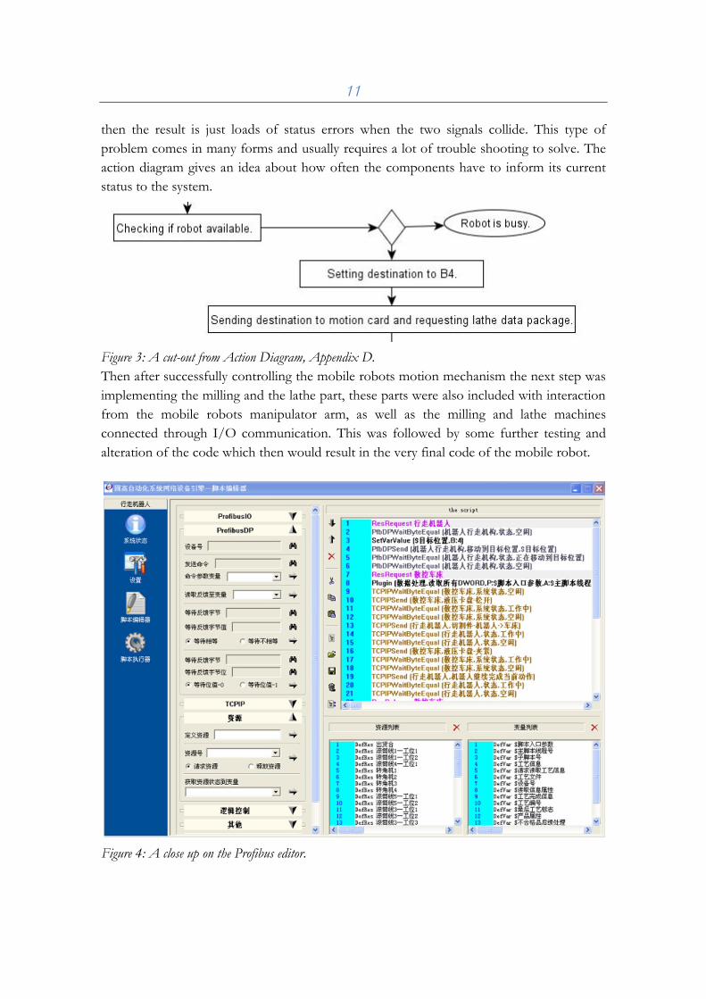
displayed in Chinese. Not to mention the code editor to write and import functions, see
Figure 4. With this in mind all the words and phrases had to be translated completely, not
an entirely easy task since tools like software and internet based dictionaries doesn't always
give a very correct translation from Chinese to English. Luckily there was assistance to get
so the project work could continue smoothly.
After studying the script language for a while it all started to make sense. It really does
work great controlling bigger comprehensive systems and it has a great share of flexibility
when it comes to dealing with different tasks.
When finished translating the code editor and a lot of scripts, the actual programming and
testing could finally take part. At first there were some execution and configuration
problems with the Profibus software and therefore the progress was quite slowly. But after
a while of studying, and a while of waiting, the system was running and it was finally
possible to try some codes out.
The first codes was basically just some simple commands to find the robots home position,
check components statuses, import and export components data packages and also some
other simple functions. All the programming code as well as the functions could be found
in older already used application, so studying them helped a lot. However studying the
documentation and some plain trial and error was still necessary to be able to understand
the Chinese programming language of Profibus. See Figure 3 for a view over the Profibus
editor.
In the first trial of the code there were a few errors and the robot wouldn't move at all. The
most errors was related to the mobile robots positioning on the rail, in an application it’s
necessary to continuously report back from the hardware where the robot currently is to
avoid physical collisions and problems. Yet by this way it might cause a lot of problem if
the reports from the hardware are misinterpreted or wrong. Actually in the mobile robot
application there occurred a few problems like this, in the laboratory the computer clients
are all connected with some certain devices and they have their own configuration to work
after, but with slightly changes in one clients settings can cause a lot of misunderstanding
for others, or even for the whole Profibus system in matter of fact. So when trying a lot of
experimental configurations and also programming the application at the same time the
results wasn’t always very rational. For example one client occupies the robot with a
process and another client (and the user for the matter of fact) isn’t aware of the matter
11
then the result is just loads of status errors when the two signals collide. This type of
problem comes in many forms and usually requires a lot of trouble shooting to solve. The
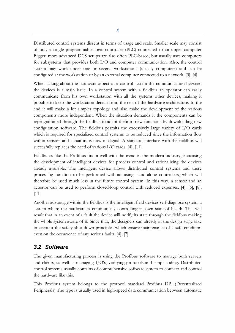
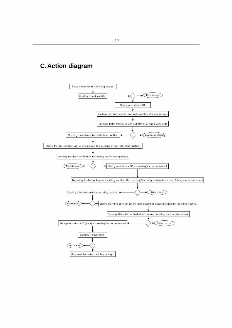
action diagram gives an idea about how often the components have to inform its current
status to the system.
Figure 3: A cut-out from Action Diagram, Appendix D.
Then after successfully controlling the mobile robots motion mechanism the next step was
implementing the milling and the lathe part, these parts were also included with interaction
from the mobile robots manipulator arm, as well as the milling and lathe machines
connected through I/O communication. This was followed by some further testing and
alteration of the code which then would result in the very final code of the mobile robot.
Figure 4: A close up on the Profibus editor.
12
5 Results and conclusions
To create a program from scratch to control a system of this magnitude and complexity
requires tremendous amount of work and time. Therefore the value of a functioning
program like Profibus values high. In the very beginning of the project there was an actual
plan to try to do an exception from the Profibus software and create a standalone
application to control the mobile robot. The idea was to create an application in C++ and
then use Dynamic-link library (DLL) to call commands to the motion card through either
Ethernet or Profibus communication. It is a possible way to control the mobile robot in
this way of course; if there was time, right preparation and a more familiar setting to do
such a project it could have been a good way. Unfortunately there wasn't much time, after
arriving to Shanghai and later receiving the project the timetable didn't turn out to be
suitable at all for the first plan. No harm done, the second plan took place and the work of
learning and programming the Profibus started.
The task to successfully understand the system of the mobile robot ended up to taking a lot
more time than the actual process of programming and testing it. There were a lot of
recommended manuals to read, both about the motion card and the Motoman robot,
manuals considering I/O, electrical wirings and software solutions. Reading the
documentation was very enlightening and it helped a lot to understand the foundation of
the system. However in the end, Profibus's own material turned out to be the most helpful
tool for the actual programming of this project. Fortunately hardware configurations
weren’t necessary for this study, understanding the hardware was enough work already, the
Profibus had already been configured up to handle the hardware aspects such as the data
transmission and the network connectivity for example.
It took a fair amount of time getting started with the actual programming and the testing,
partly because the need of a teachers assistances to get started and also sometimes simply
lack of knowledge. There were some problems with e.g. which computer belonging to
which sub-system and how to set up the systems different configurations. Even though I
did document and translate a lot of the environment in the manufacturing process, both
the hardware and the software aspects, translating everything would have been completely
impossible considering the time schedule. With other words language problems were not
an uncommon occurrence during the project. Nevertheless, most of the problems were
overcome fairly soon after they appeared.
The result of planning and executing the project was overall a very constructive and
instructive experience. Studying the different parts of the manufacturing process gave a
very wide view of how the system works. But also, the study gave a lot of insight in specific
sub-systems and components of the process such as the control system and the motion
card.
13
The most interesting part of this project must be the fact that it is collaboration between
two universities from two different countries, both very geographically and cultural far
from each other. But not to forget the fact that we all share a lot of interests together,
regarding many things, technology and engineering is just one examples of this. With
China's longtime fast industrial development and Sweden's innovative solutions and
products, there are a lot of reasons for both sides to exchange knowledge and experiences
with each other. It is a promising step towards the future industrial science.
Personally, I think staying in the laboratory of SUES gave me a good picture of modern
research and development in the fields of robotics and mechatronics. The experimental
research of an automatic manufacturing processes, included with robots, a distributed
control system and other high-technology components, state as a good example for the fact
that the industry is only heading for more and more intelligent systems and solution to
improve the processes of manufacturing. This is what many manufacturers all over the
world are working on to successfully accomplish, commonly with their main goal to reduce
the need for human intervention and simply maximizing the profits. Although it is
important to not forget that in many cases the use of humans is just far more cost-effective
than implementing automatic technology, even when automation of industrial tasks is
possible.
Even so, nothing can prevent the fact that automation plays a longtime important and
increasing role in the world economy.
14
6 References
1. HEMEIDA, A. M., EL-SADEK, M. Z. & YOUNIES, S. A. 2005. Distributed
control system approach for a unified power system. Universities Power
Engineering Conference, 2004. UPEC 2004. 39th International
2. 2006. Foundation Fieldbus [Online]. Fieldbus Foundation. Available:
http://www.fieldbus.org/ [Accessed].
3. 1999-2010. Distributed Control Systems (DCS) [Online]. GlobalSpec. Available:
http://www.globalspec.com/learnmore/networking_communication_equipment/
networking_equipment/distributed_control_systems_dcs [Accessed].
4. SALVATORE CAVALIERI, A. D. S., AND ORAZIO MIRABELLA, MEMBER,
IEEE 1997. Impact of Fieldbus on Communication in Robotic Systems. 13.
5. VITTURI, S. DP-Ethernet: the Profibus DP protocol implemented on Ethernet.
Computer Communications, 26.
6. CHEN MEICHENG, X. J., FANG YANJUN 2005. Implementation of Fully
Integrated Automation with PROFIBUS.
7. MING RAO, H. Y. A. H. Y. 1997. Integrated distributed intelligent system
architecture for incidents monitoring and diagnosis. Computers in Industry, 61,
727-806.
8. HONG, S. H. 2000. Experimental Performance Evaluation of Profibus-EMS.
9. PROF. DR.-ING. HABIL. P. NEUMANN, R. S. 1996. Free Configurable
Function Block Application Software in Distributed Control Systems.
10. LEITÃO, P. 2008. Agent-based distributed manufacturing control: A state-of-the-
art survey. Engineering Applications of Artificial Intelligence.
11. EDUARDO ANDRÉ MOSSINA, R. P. P. A. D. B. 2008. A fieldbus simulator for
training purposes. 48.
12. FUMIO KANEHIRO, Y. I., HAJIME SAITO, KAZUHIKO AKACHI, GOU
MIYAMORI, TAKAKATSU ISOZUMI, KENJI KANEKO AND HIROHISA
HIRUKAWA. 2006. Distributed Control System of Humanoid Robotsbased on
Real-time Ethernet.
13. FIROOZSHAHI, A. 2009. Innovative Intelligent DCS based method for
TankGauging Control System in Large Oil Terminal. IEEE International
Symposium on Industrial Electronics.
15
14. 2008. Electrical drawing - System Control Cabinet Power Distribution (电气图纸
- 系统配电控制柜). Googol Technology Limited.
15. 2008. Scripting help 2.0 (脚本使用说明 V2.00). Googol Technology Limited.
16
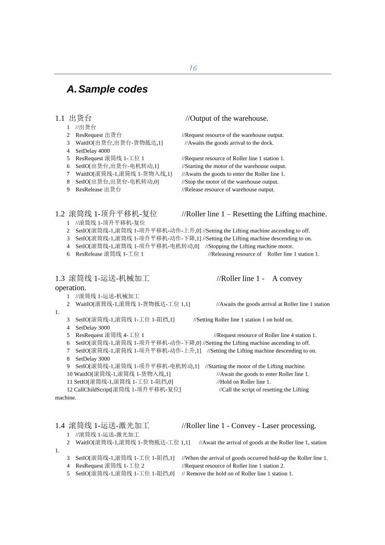
A. Sample codes
1.1 出货台 //Output of the warehouse. 1 //出货台
2 ResRequest 出货台 //Request resource of the warehouse output.
3 WaitIO[出货台,出货台-货物抵达,1] //Awaits the goods arrival to the dock.
4 SetDelay 4000
5 ResRequest 滚筒线 1-工位 1 //Request resource of Roller line 1 station 1.
6 SetIO[出货台,出货台-电机转动,1] //Starting the motor of the warehouse output.
7 WaitIO[滚筒线-1,滚筒线 1-货物入线,1] //Awaits the goods to enter the Roller line 1.
8 SetIO[出货台,出货台-电机转动,0] //Stop the motor of the warehouse output.
9 ResRelease 出货台 //Release resource of warehouse output.
1.2 滚筒线 1-顶升平移机-复位 //Roller line 1 – Resetting the Lifting machine. 1 //滚筒线 1-顶升平移机-复位
2 SetIO[滚筒线-1,滚筒线 1-项升平移机-动作-上升,0] //Setting the Lifting machine ascending to off.
3 SetIO[滚筒线-1,滚筒线 1-项升平移机-动作-下降,1] //Setting the Lifting machine descending to on.
4 SetIO[滚筒线-1,滚筒线 1-项升平移机-电机转动,0] //Stopping the Lifting machine motor.
6 ResRelease 滚筒线 1-工位 1 //Releasing resource of Roller line 1 station 1.
1.3 滚筒线 1-运送-机械加工 //Roller line 1 - A convey
operation. 1 //滚筒线 1-运送-机械加工
2 WaitIO[滚筒线-1,滚筒线 1-货物抵达-工位 1,1] //Awaits the goods arrival at Roller line 1 station
1.
3 SetIO[滚筒线-1,滚筒线 1-工位 1-阻挡,1] //Setting Roller line 1 station 1 on hold on.
4 SetDelay 3000
5 ResRequest 滚筒线 4-工位 1 //Request resource of Roller line 4 station 1.
6 SetIO[滚筒线-1,滚筒线 1-项升平移机-动作-下降,0] //Setting the Lifting machine ascending to off.
7 SetIO[滚筒线-1,滚筒线 1-项升平移机-动作-上升,1] //Setting the Lifting machine descending to on.
8 SetDelay 3000
9 SetIO[滚筒线-1,滚筒线 1-项升平移机-电机转动,1] //Starting the motor of the Lifting machine.
10 WaitIO[滚筒线-1,滚筒线 1-货物入线,1] //Await the goods to enter Roller line 1.
11 SetIO[滚筒线-1,滚筒线 1-工位 1-阻挡,0] //Hold on Roller line 1.
12 CallChildScript[滚筒线 1-项升平移机-复位] //Call the script of resetting the Lifting
machine.
1.4 滚筒线 1-运送-激光加工 //Roller line 1 - Convey - Laser processing. 1 //滚筒线 1-运送-激光加工
2 WaitIO[滚筒线-1,滚筒线 1-货物抵达-工位 1,1] //Await the arrival of goods at the Roller line 1, station
1.
3 SetIO[滚筒线-1,滚筒线 1-工位 1-阻挡,1] //When the arrival of goods occurred hold-up the Roller line 1.
4 ResRequest 滚筒线 1-工位 2 //Request resource of Roller line 1 station 2.
5 SetIO[滚筒线-1,滚筒线 1-工位 1-阻挡,0] // Remove the hold on of Roller line 1 station 1.
17
6 WaitIO[滚筒线-1,滚筒线 1-货物抵达-工位 1,0] //Await the arrival of goods to finish.
7 WaitIO[滚筒线-1,滚筒线 1-货物抵达-工位 2,1] //Await the arrival of the above mentioned goods to
reach //station 2.
8 ResRelease 滚筒线 1-工位 1 //Release resource of Roller line 1 station 1.
9 ResRequest 转角机 1 // Request resource of Right-angle Corner Platform 1.
10 SetIO[转角机-1,转角机 1-旋转-顺时针,0] //Set clockwise rotation of Right-angle Corner Platform 1 off.
11 SetIO[转角机-1,转角机 1-旋转-逆时针,1] //Set the counterclockwise rotation of Right-angle Corner
//Platform 1 on.
12 WaitIO[转角机-1,转角机 1-到位-逆时针,1] //Await Right-angle Corner Platform 1 to reach the
//counterclockwise rotation.
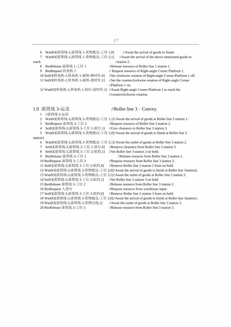
1.9 滚筒线 3-运送 //Roller line 3 – Convey. 1 //滚筒线 3-运送
2 WaitIO[滚筒线-3,滚筒线 3-货物抵达-工位 1,1]//Await the arrival of goods at Roller line 3 station 1-
3 ResRequest 滚筒线 3-工位 2 //Request resource of Roller line 3 station 2.
4 SetIO[滚筒线-3,滚筒线 3-工位 1-放行,1] //Give clearance to Roller line 3 station 3.
5 WaitIO[滚筒线-3,滚筒线 3-货物抵达-工位 1,0]//Await the arrival of goods to finish at Roller line 3
station1.
6 WaitIO[滚筒线-3,滚筒线 3-货物抵达-工位 2,1]//Await the outlet of goods at Roller line 3 station 2.
7 SetIO[滚筒线-3,滚筒线 3-工位 1-放行,0] //Remove clearance from Roller line 3 station 3.
8 SetIO[滚筒线-3,滚筒线 3-工位 2-阻挡,1] //Set Roller line 3 station 2 on hold.
9 ResRelease 滚筒线 3-工位 1 //Release resource from Roller line 3 station 1.
10 ResRequest 滚筒线 3-工位 3 //Request resource from Roller line 3 station 3.
11 SetIO[滚筒线-3,滚筒线 3-工位 2-阻挡,0] //Remove Roller line 3 station 2 from on hold.
12 WaitIO[滚筒线-3,滚筒线 3-货物抵达-工位 2,0]//Await the arrival of goods to finish at Roller line 3station2.
13 WaitIO[滚筒线-3,滚筒线 3-货物抵达-工位 3,1]//Await the outlet of goods at Roller line 3 station 3.
14 SetIO[滚筒线-3,滚筒线 3-工位 3-阻挡,1] //Set Roller line 3 station 3 on hold.
15 ResRelease 滚筒线 3-工位 2 //Release resource from Roller line 3 station 2.
16 ResRequest 入货台 //Request resource from warehouse input.
17 SetIO[滚筒线-3,滚筒线 3-工位 3-阻挡,0] //Remove Roller line 3 station 3 from on hold.
18 WaitIO[滚筒线-3,滚筒线 3-货物抵达-工位 3,0]//Await the arrival of goods to finish at Roller line 3station1.
19 WaitIO[滚筒线-3,滚筒线 3-货物出线,1] //Await the outlet of goods at Roller line 3 station 3.
20 ResRelease 滚筒线 3-工位 3 //Release resource from Roller line 3 station 3.
18
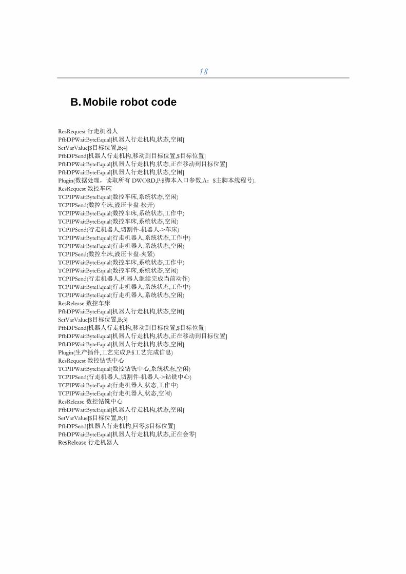
B. Mobile robot code
ResRequest 行走机器人
PfbDPWaitByteEqual[机器人行走机构,状态,空闲]
SetVarValue[$目标位置,B;4]
PfbDPSend[机器人行走机构,移动到目标位置,$目标位置]
PfbDPWaitByteEqual[机器人行走机构,状态,正在移动到目标位置]
PfbDPWaitByteEqual[机器人行走机构,状态,空闲]
Plugin(数据处理,读取所有 DWORD,P:$脚本入口参数,A:$主脚本线程号).
ResRequest 数控车床
TCPIPWaitByteEqual(数控车床,系统状态,空闲)
TCPIPSend(数控车床,液压卡盘-松开)
TCPIPWaitByteEqual(数控车床,系统状态,工作中)
TCPIPWaitByteEqual(数控车床,系统状态,空闲)
TCPIPSend(行走机器人,切割件-机器人->车床)
TCPIPWaitByteEqual(行走机器人,系统状态,工作中)
TCPIPWaitByteEqual(行走机器人,系统状态,空闲)
TCPIPSend(数控车床,液压卡盘-夹紧)
TCPIPWaitByteEqual(数控车床,系统状态,工作中)
TCPIPWaitByteEqual(数控车床,系统状态,空闲)
TCPIPSend(行走机器人,机器人继续完成当前动作)
TCPIPWaitByteEqual(行走机器人,系统状态,工作中)
TCPIPWaitByteEqual(行走机器人,系统状态,空闲)
ResRelease 数控车床
PfbDPWaitByteEqual[机器人行走机构,状态,空闲]
SetVarValue[$目标位置,B;3]
PfbDPSend[机器人行走机构,移动到目标位置,$目标位置]
PfbDPWaitByteEqual[机器人行走机构,状态,正在移动到目标位置]
PfbDPWaitByteEqual[机器人行走机构,状态,空闲]
Plugin(生产插件,工艺完成,P:$工艺完成信息)
ResRequest 数控钻铣中心
TCPIPWaitByteEqual(数控钻铣中心,系统状态,空闲)
TCPIPSend(行走机器人,切割件-机器人->钻铣中心)
TCPIPWaitByteEqual(行走机器人,状态,工作中)
TCPIPWaitByteEqual(行走机器人,状态,空闲)
ResRelease 数控钻铣中心
PfbDPWaitByteEqual[机器人行走机构,状态,空闲]
SetVarValue[$目标位置,B;1]
PfbDPSend[机器人行走机构,回零,$目标位置]
PfbDPWaitByteEqual[机器人行走机构,状态,正在会零]
ResRelease 行走机器人
19
C. Action diagram
20
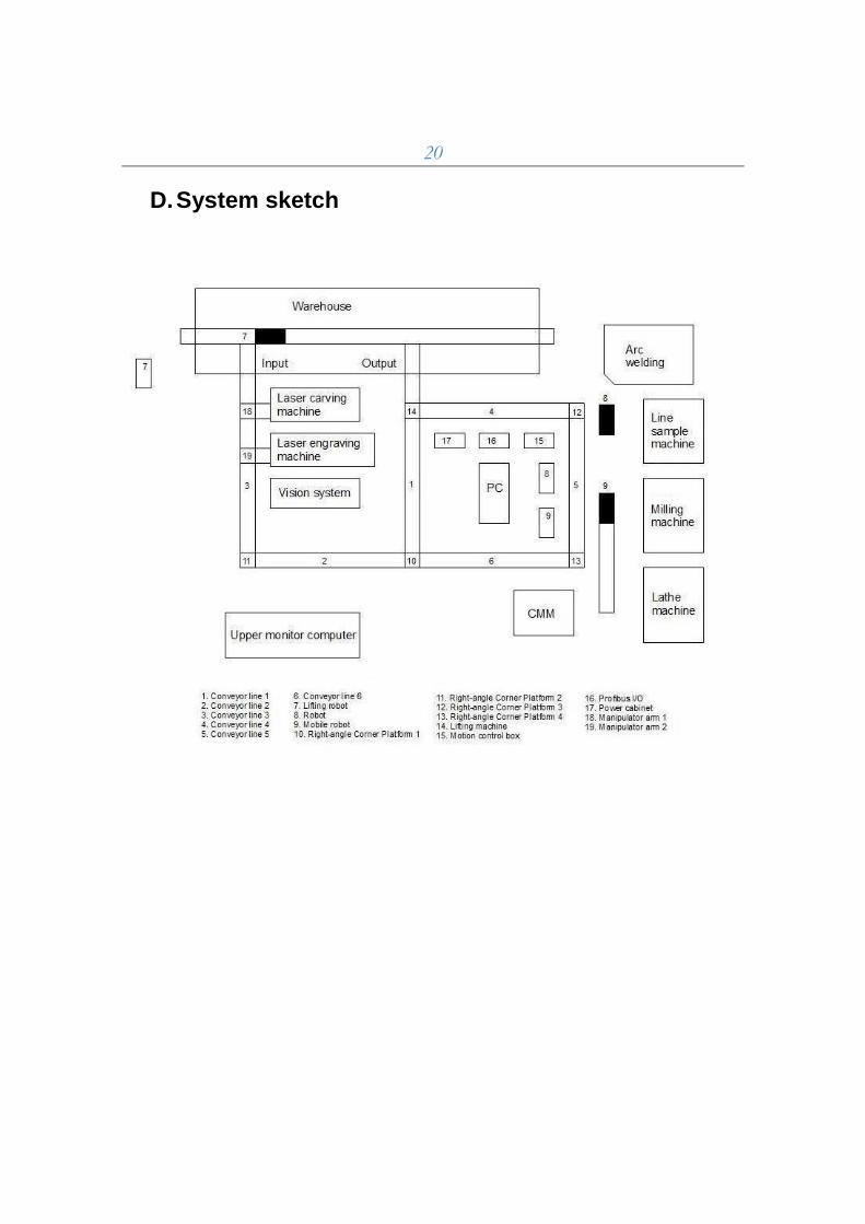
D. System sketch
21
E. Dictionary
1. 设备号 – Device ID
2. 激光内雕机 – Inner laser engraving machine
3. 激光外雕机 – Outer laser engraving machine
4. 机器人行走机构 – Robot motion mechanism
5. 回零 – Go back to zero
6. 发送命令 – Send command
7. 工位 - Station
8. 加工 – Process
9. 停止 – Stop/Interuption
10. 启动 – Start/Trigger
11. 暂停 – Suspend/time out
12. 继续 – Continue/go on
13. 从故障中复 - Recovery from failures
14. 移动到接料位 - Move to accept Level
15. 移动到原点位置 - Move to the origin location
16. 参数 – Parameter
17. 无 – Not have
18. 命令参数变量 – Command variables
19. 读取反馈至变量 – Read feedback to the variables
20. 等待反馈字节 – Wait for the feedback byte
21. 等待反馈字节值 – Wait for the feedback byte value
22. 空闲 – Leisure
23. 正在移动到目标位置 – Moving to the target location
24. 正在回零 – Moving to zero
25. 未就绪 – Not ready
26. 故障 – Failure
27. 无障碍 – No object /barrier free
28. 随机原点 – Random origin
29. 命令溢出 – Command overflow
30. GT控制器错误 - GT controller error
31. 无效的目标位置 – Invalid Destination
32. 等待相等 - Wait for equality
33. 等待不相等 – Wait for non equality
34. 等待位值-0 等待位值-1 – Wait for the bit values 0/1
35. 脚本入口参数 – Script input parameter
36. 机器人 - Robot
37. 故障编码 – Encoder failed
38. 状态 – Status
39. 资源 – Resource
40. 定义资源 - Define resource
41. 资源号 – Resource number
42. 请求资源 – Request resources
43. 释放资源 – Release resources
44. 获取资源状态到变量 – To obtain the resource status to variable
45. 脚本入口参数 - Script input parameter
46. 逻辑控制 – Logical Control
47. 插入标记 – Insert tag
22
48. 跳转到标记 – Jump to tag
49. 变量A – Variable A
50. 变量B – Variable B
51. 其他 – Others
52. 设定延时 – Set delay
53. 调用子脚本 – Call sub-scripts
54. 入口参数 – Entry parameter
55. 子脚本号 – Number of Sub-script
56. 等待子脚本结束 – Waiting for the end of sub-script
57. 定义变量 – Variable definition
58. 赋值变量 – Assigned variable
59. 变量赋值脚本语句 – Script variable assignment statment
60. 注释 – Notation
61. 插件 – Plugin components
62. 插件 – Plug in components/unit
63. 选择插件 – Select plugins
64. 插件说明 – Plugin help
65. 插件命令 – Plugin command
66. 命令说明 – Command direction
67. 插件注册 – Plug in registration
68. 注 插件 – Plugin notation
69. 插件文件 – Plugin files
70. 插件说明 – Plugin help
71. 选择插件 – Select plugins
72. 信息提示 – Information cue
73. 数据处理 – Data processing
74. 生产插件 – Production plug in
75. 物料信息采集插件 – Material information collection plug-in
76. 插件命令 – Plugin command
77. 命令函数 – Command function
78. 命令说明 – Command direction
79. 插件函数 – Plug-in function
80. 插件说明 – Plug-in direction
81. 传动– Transmission, driving motion
82. 仓储执行系统 (堆垛机单元控制计算机)
83. – Warehouse execution system (Stacker control computer unit)
84. 生产执行系统 (输送线单元控制计算机)
85. – Manufacturing Execution System (Transport line control computer unit)
86. 仓储管理系统 (堆垛机单元控制计算机)
87. – Warehouse Management System (Stacker control computer unit)
88. 生产管理系统 – Production management system
89. 堆垛机 嵌入式 – Embedded stacker
90. 以太网 - Ethernet
91. 输送线I/O模块 – Transmission line I / O modules
92. 数控线切割控制PC – CNC wire cutting control PC
93. 数控钻铣 控制PC – CNC drilling and milling control PC
94. 数控车床 控制PC – CNC lathe control PC
95. 焊接系统 控制PC – Welding system control PC
96. 三坐标测量机控制PC – CMM control PC
97. 激光内雕机 控制PC – Laser engraving machine control PC
98. 激光外雕机 控制PC – Laser carving machine control PC
99. 材料识别 控制PC – Material identification control PC
100. I/O 模块 - I / O modules

23
101. 合式流水线 – Conveyor belt
102. 机器人行走机构 - Mobile robot motion mechanism


![LITERATURE REVIEW CO-OPERATIVE MAPPING AND … · a single, controlling robot (The Master robot as mentioned in [18]) or whether each robot is independent and communicates with every](https://img.pdfslide.net/doc/110x75/5f581dce8fea484b3020afd9/literature-review-co-operative-mapping-and-a-single-controlling-robot-the-master.jpg)