Embed Size (px)
Citation preview

ControlLogix HART Analog I/O ModulesCatalog Numbers 1756-IF8H, 1756-IF8IH, 1756-IF16H, 1756-IF16IH, 1756-OF8H, 1756-OF8IH
User ManualOriginal Instructions
Important User Information
Read this document and the documents listed in the additional resources section about installation, configuration, and operation of this equipment before you install, configure, operate, or maintain this product. Users are required to familiarize themselves with installation and wiring instructions in addition to requirements of all applicable codes, laws, and standards.
Activities including installation, adjustments, putting into service, use, assembly, disassembly, and maintenance are required to be carried out by suitably trained personnel in accordance with applicable code of practice.
If this equipment is used in a manner not specified by the manufacturer, the protection provided by the equipment may be impaired.
In no event will Rockwell Automation, Inc. be responsible or liable for indirect or consequential damages resulting from the use or application of this equipment.
The examples and diagrams in this manual are included solely for illustrative purposes. Because of the many variables and requirements associated with any particular installation, Rockwell Automation, Inc. cannot assume responsibility or liability for actual use based on the examples and diagrams.
No patent liability is assumed by Rockwell Automation, Inc. with respect to use of information, circuits, equipment, or software described in this manual.
Reproduction of the contents of this manual, in whole or in part, without written permission of Rockwell Automation, Inc., is prohibited.
Throughout this manual, when necessary, we use notes to make you aware of safety considerations.
Labels may also be on or inside the equipment to provide specific precautions.
WARNING: Identifies information about practices or circumstances that can cause an explosion in a hazardous environment, which may lead to personal injury or death, property damage, or economic loss.
ATTENTION: Identifies information about practices or circumstances that can lead to personal injury or death, property damage, or economic loss. Attentions help you identify a hazard, avoid a hazard, and recognize the consequence.
IMPORTANT Identifies information that is critical for successful application and understanding of the product.
SHOCK HAZARD: Labels may be on or inside the equipment, for example, a drive or motor, to alert people that dangerous voltage may be present.
BURN HAZARD: Labels may be on or inside the equipment, for example, a drive or motor, to alert people that surfaces may reach dangerous temperatures.
ARC FLASH HAZARD: Labels may be on or inside the equipment, for example, a motor control center, to alert people to potential Arc Flash. Arc Flash will cause severe injury or death. Wear proper Personal Protective Equipment (PPE). Follow ALL Regulatory requirements for safe work practices and for Personal Protective Equipment (PPE).
Table of Contents
Preface . . . . . . . . . . . . . . . . . . . . . . . . . . . . . . . . . . . . . . . . . . . . . . . . . . . . . . .11Summary of Changes . . . . . . . . . . . . . . . . . . . . . . . . . . . . . . . . . . . . . . . . . . 11Additional Resources . . . . . . . . . . . . . . . . . . . . . . . . . . . . . . . . . . . . . . . . . . 11
Chapter 1ControlLogix HART Analog I/O Modules
Module Components . . . . . . . . . . . . . . . . . . . . . . . . . . . . . . . . . . . . . . . . . . 14Module Accessories. . . . . . . . . . . . . . . . . . . . . . . . . . . . . . . . . . . . . . . . . . . . 15Key the Removable Terminal Block/Interface Module . . . . . . . . . . . 16HART Communication . . . . . . . . . . . . . . . . . . . . . . . . . . . . . . . . . . . . . . . 17
Integrated HART Networks . . . . . . . . . . . . . . . . . . . . . . . . . . . . . . . 18HART-enabled I/O Modules . . . . . . . . . . . . . . . . . . . . . . . . . . . . . . 18
Asset Management Software . . . . . . . . . . . . . . . . . . . . . . . . . . . . . . . . . . . 19Timestamping . . . . . . . . . . . . . . . . . . . . . . . . . . . . . . . . . . . . . . . . . . . . . . . . 19Module Scaling . . . . . . . . . . . . . . . . . . . . . . . . . . . . . . . . . . . . . . . . . . . . . . . 19Electronic Keying . . . . . . . . . . . . . . . . . . . . . . . . . . . . . . . . . . . . . . . . . . . . . 20
More Information . . . . . . . . . . . . . . . . . . . . . . . . . . . . . . . . . . . . . . . . . 20
Chapter 2ControlLogix Module Operation Direct Connections . . . . . . . . . . . . . . . . . . . . . . . . . . . . . . . . . . . . . . . . . . . 22
Input Module Operation . . . . . . . . . . . . . . . . . . . . . . . . . . . . . . . . . . . . . . 22Input Modules in a Local Chassis . . . . . . . . . . . . . . . . . . . . . . . . . . . . . . . 23
Real Time Sample (RTS). . . . . . . . . . . . . . . . . . . . . . . . . . . . . . . . . . . 23Requested Packet Interval (RPI) . . . . . . . . . . . . . . . . . . . . . . . . . . . . 24Trigger Event Tasks . . . . . . . . . . . . . . . . . . . . . . . . . . . . . . . . . . . . . . . 25
Input Modules in a Remote Chassis. . . . . . . . . . . . . . . . . . . . . . . . . . . . . 26Remote Input Modules Connected Via ControlNet Network . . . . . . . . . . . . . . . . . . . . . . . . . . . . . . . . . . . . . . 26Remote Input Modules Connected Via EtherNet/IP Network . . . . . . . . . . . . . . . . . . . . . . . . . . . . . . . . . . . . . 27
Output Module Operation. . . . . . . . . . . . . . . . . . . . . . . . . . . . . . . . . . . . . 28Output Modules in a Local Chassis . . . . . . . . . . . . . . . . . . . . . . . . . . . . . 28Output Modules in a Remote Chassis . . . . . . . . . . . . . . . . . . . . . . . . . . . 29
Remote Output Modules Connected Via ControlNet Network . . . . . . . . . . . . . . . . . . . . . . . . . . . . . . . . . . . . . . 29Remote Output Modules Connected Via EtherNet/IP Network . . . . . . . . . . . . . . . . . . . . . . . . . . . . . . . . . . . . . 30
Listen-only Mode . . . . . . . . . . . . . . . . . . . . . . . . . . . . . . . . . . . . . . . . . . . . . 30Multiple Owners of Input Modules . . . . . . . . . . . . . . . . . . . . . . . . . . . . . 31Configuration Changes in an Input Module with Multiple Owners . . . . . . . . . . . . . . . . . . . . . . . . . . . . . . . . . . . . . . . . . . . . . . 32Unicast Communication . . . . . . . . . . . . . . . . . . . . . . . . . . . . . . . . . . . . . . 32
Rockwell Automation Publication 1756-UM533E-EN-P - November 2016 3
Table of Contents
Chapter 31756-IF8H HART Analog Input Module
Module Features . . . . . . . . . . . . . . . . . . . . . . . . . . . . . . . . . . . . . . . . . . . . . . 33Data Formats . . . . . . . . . . . . . . . . . . . . . . . . . . . . . . . . . . . . . . . . . . . . . 34Input Ranges . . . . . . . . . . . . . . . . . . . . . . . . . . . . . . . . . . . . . . . . . . . . . . 34Module Filter . . . . . . . . . . . . . . . . . . . . . . . . . . . . . . . . . . . . . . . . . . . . . 35Real-time Sampling . . . . . . . . . . . . . . . . . . . . . . . . . . . . . . . . . . . . . . . . 36Underrange and Overrange Detection. . . . . . . . . . . . . . . . . . . . . . . 36Digital Filter . . . . . . . . . . . . . . . . . . . . . . . . . . . . . . . . . . . . . . . . . . . . . . 37Process Alarms . . . . . . . . . . . . . . . . . . . . . . . . . . . . . . . . . . . . . . . . . . . . 38Rate Alarm. . . . . . . . . . . . . . . . . . . . . . . . . . . . . . . . . . . . . . . . . . . . . . . . 39Wire-off Detection . . . . . . . . . . . . . . . . . . . . . . . . . . . . . . . . . . . . . . . . 39
Wire the Module . . . . . . . . . . . . . . . . . . . . . . . . . . . . . . . . . . . . . . . . . . . . . . 40Circuit Diagrams. . . . . . . . . . . . . . . . . . . . . . . . . . . . . . . . . . . . . . . . . . . . . . 421756-IF8H Module Fault and Status Reporting. . . . . . . . . . . . . . . . . . 43
1756-IF8H Fault Reporting . . . . . . . . . . . . . . . . . . . . . . . . . . . . . . . . 441756-IF8H Module Fault Word Bits . . . . . . . . . . . . . . . . . . . . . . . . 451756-IF8H Channel Fault Tags . . . . . . . . . . . . . . . . . . . . . . . . . . . . 451756-IF8H Channel Status Tags. . . . . . . . . . . . . . . . . . . . . . . . . . . . 46
1756-IF8H Tag Definitions. . . . . . . . . . . . . . . . . . . . . . . . . . . . . . . . . . . . 46Configuration. . . . . . . . . . . . . . . . . . . . . . . . . . . . . . . . . . . . . . . . . . . . . 47Analog Only . . . . . . . . . . . . . . . . . . . . . . . . . . . . . . . . . . . . . . . . . . . . . . 48Analog and HART PV. . . . . . . . . . . . . . . . . . . . . . . . . . . . . . . . . . . . . 49Analog and HART by Channel . . . . . . . . . . . . . . . . . . . . . . . . . . . . . 51
Chapter 41756-IF8IH HART Isolated Analog Input Module
Module Features . . . . . . . . . . . . . . . . . . . . . . . . . . . . . . . . . . . . . . . . . . . . . . 53HART Compatibility. . . . . . . . . . . . . . . . . . . . . . . . . . . . . . . . . . . . . . 54HART Handheld Configurator . . . . . . . . . . . . . . . . . . . . . . . . . . . . 54Data Formats . . . . . . . . . . . . . . . . . . . . . . . . . . . . . . . . . . . . . . . . . . . . . 55Input Ranges . . . . . . . . . . . . . . . . . . . . . . . . . . . . . . . . . . . . . . . . . . . . . . 55Module Filter . . . . . . . . . . . . . . . . . . . . . . . . . . . . . . . . . . . . . . . . . . . . . 56Digital Filter . . . . . . . . . . . . . . . . . . . . . . . . . . . . . . . . . . . . . . . . . . . . . . 57Real-time Sampling . . . . . . . . . . . . . . . . . . . . . . . . . . . . . . . . . . . . . . . . 58Underrange and Overrange Detection. . . . . . . . . . . . . . . . . . . . . . . 58Open Circuit Detection. . . . . . . . . . . . . . . . . . . . . . . . . . . . . . . . . . . . 58Auto-Configure HART Device. . . . . . . . . . . . . . . . . . . . . . . . . . . . . 59Rate Alarm. . . . . . . . . . . . . . . . . . . . . . . . . . . . . . . . . . . . . . . . . . . . . . . . 59Process Alarms . . . . . . . . . . . . . . . . . . . . . . . . . . . . . . . . . . . . . . . . . . . . 60
Wire the Module . . . . . . . . . . . . . . . . . . . . . . . . . . . . . . . . . . . . . . . . . . . . . . 61Circuit Diagram . . . . . . . . . . . . . . . . . . . . . . . . . . . . . . . . . . . . . . . . . . . . . . 611756-IF8IH Module Fault and Status Reporting. . . . . . . . . . . . . . . . . 62
1756-IF8IH Module Fault Word Bits . . . . . . . . . . . . . . . . . . . . . . . 631756-IF8IH Channel Fault Tags. . . . . . . . . . . . . . . . . . . . . . . . . . . . 63
Module Calibration . . . . . . . . . . . . . . . . . . . . . . . . . . . . . . . . . . . . . . . . . . . 64Module Calibration Via Logix Designer Application . . . . . . . . . 64Module Calibration Via Output Word . . . . . . . . . . . . . . . . . . . . . . 64
4 Rockwell Automation Publication 1756-UM533E-EN-P - November 2016
Table of Contents
Module-defined Data Types, 1756-IF8IH Module . . . . . . . . . . . . . . . 65Configuration - Configure HART Device = No . . . . . . . . . . . . . 65Configuration - Configure HART Device = Yes . . . . . . . . . . . . . 66Input - Analog Only . . . . . . . . . . . . . . . . . . . . . . . . . . . . . . . . . . . . . . . 67Input - Analog and HART PV. . . . . . . . . . . . . . . . . . . . . . . . . . . . . . 68Input - Analog and HART by Channel, Configure HART Device = No. . . . . . . . . . . . . . . . . . . . . . . . . . . . . 70Input - Analog and HART by Channel, Configure HART Device = Yes . . . . . . . . . . . . . . . . . . . . . . . . . . . . 72Output - Analog and HART by Channel, Configure HART Device = Yes . . . . . . . . . . . . . . . . . . . . . . . . . . . . 74
Chapter 51756-IF16H HART Analog Input Module
Module Features . . . . . . . . . . . . . . . . . . . . . . . . . . . . . . . . . . . . . . . . . . . . . . 75Data Formats . . . . . . . . . . . . . . . . . . . . . . . . . . . . . . . . . . . . . . . . . . . . . 76Input Ranges . . . . . . . . . . . . . . . . . . . . . . . . . . . . . . . . . . . . . . . . . . . . . . 76Module Filter . . . . . . . . . . . . . . . . . . . . . . . . . . . . . . . . . . . . . . . . . . . . . 77Real-time Sampling (RTS) . . . . . . . . . . . . . . . . . . . . . . . . . . . . . . . . . 78Underrange and Overrange Detection. . . . . . . . . . . . . . . . . . . . . . . 78Digital Filter . . . . . . . . . . . . . . . . . . . . . . . . . . . . . . . . . . . . . . . . . . . . . . 79Wire-off Detection . . . . . . . . . . . . . . . . . . . . . . . . . . . . . . . . . . . . . . . . 80
Wire the Module . . . . . . . . . . . . . . . . . . . . . . . . . . . . . . . . . . . . . . . . . . . . . . 80Circuit Diagram . . . . . . . . . . . . . . . . . . . . . . . . . . . . . . . . . . . . . . . . . . . . . . 821756-IF16H Module Fault and Status Reporting . . . . . . . . . . . . . . . . 83
1756-IF16H Module Fault Reporting . . . . . . . . . . . . . . . . . . . . . . . 841756-IF16H Module Fault Word Bits. . . . . . . . . . . . . . . . . . . . . . . 851756-IF16H Channel Fault Tags . . . . . . . . . . . . . . . . . . . . . . . . . . . 851756-IF16H Channel Status Tags . . . . . . . . . . . . . . . . . . . . . . . . . . 85
Module-defined Data Types, 1756-IF16H Module. . . . . . . . . . . . . . . 86Configuration. . . . . . . . . . . . . . . . . . . . . . . . . . . . . . . . . . . . . . . . . . . . . 86Analog Only . . . . . . . . . . . . . . . . . . . . . . . . . . . . . . . . . . . . . . . . . . . . . . 87Analog and HART PV. . . . . . . . . . . . . . . . . . . . . . . . . . . . . . . . . . . . . 88Analog and HART by Channel . . . . . . . . . . . . . . . . . . . . . . . . . . . . . 89
Chapter 61756-IF16IH HART Analog Input Module
Module Features . . . . . . . . . . . . . . . . . . . . . . . . . . . . . . . . . . . . . . . . . . . . . . 91HART Compatibility. . . . . . . . . . . . . . . . . . . . . . . . . . . . . . . . . . . . . . 92HART Handheld Configurator . . . . . . . . . . . . . . . . . . . . . . . . . . . . 92Data Formats . . . . . . . . . . . . . . . . . . . . . . . . . . . . . . . . . . . . . . . . . . . . . 93Input Ranges . . . . . . . . . . . . . . . . . . . . . . . . . . . . . . . . . . . . . . . . . . . . . . 93Module Filter . . . . . . . . . . . . . . . . . . . . . . . . . . . . . . . . . . . . . . . . . . . . . 93Digital Filter . . . . . . . . . . . . . . . . . . . . . . . . . . . . . . . . . . . . . . . . . . . . . . 95Real-time Sampling . . . . . . . . . . . . . . . . . . . . . . . . . . . . . . . . . . . . . . . . 96Underrange and Overrange Detection. . . . . . . . . . . . . . . . . . . . . . . 96Open Circuit Detection. . . . . . . . . . . . . . . . . . . . . . . . . . . . . . . . . . . . 96
Wire the Module . . . . . . . . . . . . . . . . . . . . . . . . . . . . . . . . . . . . . . . . . . . . . . 97
Rockwell Automation Publication 1756-UM533E-EN-P - November 2016 5
Table of Contents
Circuit Diagram . . . . . . . . . . . . . . . . . . . . . . . . . . . . . . . . . . . . . . . . . . . . . . 981756-IF16IH Module Fault and Status Reporting . . . . . . . . . . . . . . . 99
1756-IF16IH Module Fault Word Bits. . . . . . . . . . . . . . . . . . . . . 1001756-IF16IH Channel Fault Tags . . . . . . . . . . . . . . . . . . . . . . . . . 1001756-IF16IH Channel Status Tags. . . . . . . . . . . . . . . . . . . . . . . . . 101
Module Calibration . . . . . . . . . . . . . . . . . . . . . . . . . . . . . . . . . . . . . . . . . . 101Module-defined Data Types, 1756-IF16IH Module. . . . . . . . . . . . . 101
Configuration. . . . . . . . . . . . . . . . . . . . . . . . . . . . . . . . . . . . . . . . . . . . 102Analog Only . . . . . . . . . . . . . . . . . . . . . . . . . . . . . . . . . . . . . . . . . . . . . 103Analog and HART PV. . . . . . . . . . . . . . . . . . . . . . . . . . . . . . . . . . . . 104Analog and HART PV by Channel Grouped . . . . . . . . . . . . . . . 105
Chapter 71756-OF8H HART Analog Output Module
Module Features . . . . . . . . . . . . . . . . . . . . . . . . . . . . . . . . . . . . . . . . . . . . . 107Data Formats . . . . . . . . . . . . . . . . . . . . . . . . . . . . . . . . . . . . . . . . . . . . 108Resolution . . . . . . . . . . . . . . . . . . . . . . . . . . . . . . . . . . . . . . . . . . . . . . . 108Ramping/Rate Limiting. . . . . . . . . . . . . . . . . . . . . . . . . . . . . . . . . . . 109Hold for Initialization . . . . . . . . . . . . . . . . . . . . . . . . . . . . . . . . . . . . 109Open Wire Detection. . . . . . . . . . . . . . . . . . . . . . . . . . . . . . . . . . . . . 110Clamping and Limiting . . . . . . . . . . . . . . . . . . . . . . . . . . . . . . . . . . . 110Clamp and Limit Alarms . . . . . . . . . . . . . . . . . . . . . . . . . . . . . . . . . . 110Data Echo . . . . . . . . . . . . . . . . . . . . . . . . . . . . . . . . . . . . . . . . . . . . . . . 111
Wire the Module . . . . . . . . . . . . . . . . . . . . . . . . . . . . . . . . . . . . . . . . . . . . . 111Use Module Block and Output Circuit Diagrams . . . . . . . . . . . . . . . 1121756-OF8H Module Fault and Status Reporting . . . . . . . . . . . . . . . 1131756-OF8H Fault Reporting. . . . . . . . . . . . . . . . . . . . . . . . . . . . . . . . . . 114
Module Fault Word Bits . . . . . . . . . . . . . . . . . . . . . . . . . . . . . . . . . . 115Channel Fault Word Bits . . . . . . . . . . . . . . . . . . . . . . . . . . . . . . . . . 115Channel Status Tags . . . . . . . . . . . . . . . . . . . . . . . . . . . . . . . . . . . . . . 116
Module-defined Data Types, 1756-OF8H Module. . . . . . . . . . . . . . 117Configuration. . . . . . . . . . . . . . . . . . . . . . . . . . . . . . . . . . . . . . . . . . . . 117Analog Only . . . . . . . . . . . . . . . . . . . . . . . . . . . . . . . . . . . . . . . . . . . . . 118Analog and HART PV. . . . . . . . . . . . . . . . . . . . . . . . . . . . . . . . . . . . 119Analog and HART by Channel . . . . . . . . . . . . . . . . . . . . . . . . . . . . 121Output . . . . . . . . . . . . . . . . . . . . . . . . . . . . . . . . . . . . . . . . . . . . . . . . . . 122
Chapter 81756-OF8IH HART Analog Output Module
Module Features . . . . . . . . . . . . . . . . . . . . . . . . . . . . . . . . . . . . . . . . . . . . . 123Data Formats . . . . . . . . . . . . . . . . . . . . . . . . . . . . . . . . . . . . . . . . . . . . 124Powerup State. . . . . . . . . . . . . . . . . . . . . . . . . . . . . . . . . . . . . . . . . . . . 125Fault Mode Output State . . . . . . . . . . . . . . . . . . . . . . . . . . . . . . . . . 125Ramping (Rate Limiting) . . . . . . . . . . . . . . . . . . . . . . . . . . . . . . . . . 125Hold for Initialization . . . . . . . . . . . . . . . . . . . . . . . . . . . . . . . . . . . . 126Open Wire Detection. . . . . . . . . . . . . . . . . . . . . . . . . . . . . . . . . . . . . 126Clamping (Limiting) . . . . . . . . . . . . . . . . . . . . . . . . . . . . . . . . . . . . . 126Clamp and Limit Alarms . . . . . . . . . . . . . . . . . . . . . . . . . . . . . . . . . . 127
6 Rockwell Automation Publication 1756-UM533E-EN-P - November 2016
Table of Contents
Data Echo . . . . . . . . . . . . . . . . . . . . . . . . . . . . . . . . . . . . . . . . . . . . . . . 127HART Device Auto-configuration. . . . . . . . . . . . . . . . . . . . . . . . . 127Write HART Variables . . . . . . . . . . . . . . . . . . . . . . . . . . . . . . . . . . . 127
Wire the Module . . . . . . . . . . . . . . . . . . . . . . . . . . . . . . . . . . . . . . . . . . . . . 128Output Circuit Diagram . . . . . . . . . . . . . . . . . . . . . . . . . . . . . . . . . . . . . . 1281756-OF8IH Module Fault and Status Reporting. . . . . . . . . . . . . . . 129
1756-OF8IH Module Fault Reporting . . . . . . . . . . . . . . . . . . . . . 130Module Fault Word Bits . . . . . . . . . . . . . . . . . . . . . . . . . . . . . . . . . . 131Channel Fault Word Bits . . . . . . . . . . . . . . . . . . . . . . . . . . . . . . . . . 131Channel Status Tags . . . . . . . . . . . . . . . . . . . . . . . . . . . . . . . . . . . . . . 132
Module Calibration . . . . . . . . . . . . . . . . . . . . . . . . . . . . . . . . . . . . . . . . . . 133Module Calibration Via Logix Designer Application . . . . . . . . 133Module Calibration Via Output Word . . . . . . . . . . . . . . . . . . . . . 133
Module-defined Data Types, 1756-OF8IH Module . . . . . . . . . . . . . 1341756-OF8IH Configuration, Configure HART Device = No. . . . . . . . . . . . . . . . . . . . . . . . . . . . 1341756-OF8IH Configuration, Configure HART Device = Yes . . . . . . . . . . . . . . . . . . . . . . . . . . . 1361756-OF8IH Input - Analog Only . . . . . . . . . . . . . . . . . . . . . . . . . 1371756-OF8IH Input - Analog and HART PV . . . . . . . . . . . . . . . 138Analog and HART by Channel, Configure HART Device = No. . . . . . . . . . . . . . . . . . . . . . . . . . . . 139Analog and HART by Channel, Configure HART Device = Yes . . . . . . . . . . . . . . . . . . . . . . . . . . . 141Output, Configure HART Device = No . . . . . . . . . . . . . . . . . . . 143Output, Configure HART Device = Yes . . . . . . . . . . . . . . . . . . . 143
Chapter 9Configure Modules in the Logix Designer Application
Create a New Module . . . . . . . . . . . . . . . . . . . . . . . . . . . . . . . . . . . . . . . . 145General Tab . . . . . . . . . . . . . . . . . . . . . . . . . . . . . . . . . . . . . . . . . . . . . . . . . 147
HART Configuration . . . . . . . . . . . . . . . . . . . . . . . . . . . . . . . . . . . . 148Connection Tab . . . . . . . . . . . . . . . . . . . . . . . . . . . . . . . . . . . . . . . . . . . . . 149Module Info Tab . . . . . . . . . . . . . . . . . . . . . . . . . . . . . . . . . . . . . . . . . . . . . 149
Status. . . . . . . . . . . . . . . . . . . . . . . . . . . . . . . . . . . . . . . . . . . . . . . . . . . . 150Coordinated System Time (CST). . . . . . . . . . . . . . . . . . . . . . . . . . 150Refresh or Reset Module . . . . . . . . . . . . . . . . . . . . . . . . . . . . . . . . . . 150Apply Changes . . . . . . . . . . . . . . . . . . . . . . . . . . . . . . . . . . . . . . . . . . . 151
Configuration Tab - Input Modules . . . . . . . . . . . . . . . . . . . . . . . . . . . 151Configure Individual Channels . . . . . . . . . . . . . . . . . . . . . . . . . . . . 152Scaling to Engineering Units . . . . . . . . . . . . . . . . . . . . . . . . . . . . . . 153Configure All Channels . . . . . . . . . . . . . . . . . . . . . . . . . . . . . . . . . . . 156Module Resolution . . . . . . . . . . . . . . . . . . . . . . . . . . . . . . . . . . . . . . . 157
Alarm Tab - 1756-IF8H and 1756-IF8IH Modules . . . . . . . . . . . . . 158Configuration Tab - Output Module . . . . . . . . . . . . . . . . . . . . . . . . . . 160
Configure Individual Channels . . . . . . . . . . . . . . . . . . . . . . . . . . . . 160Configure All Channels . . . . . . . . . . . . . . . . . . . . . . . . . . . . . . . . . . . 161
Rockwell Automation Publication 1756-UM533E-EN-P - November 2016 7
Table of Contents
Output State Tab - Output Module . . . . . . . . . . . . . . . . . . . . . . . . . . . 162Ramp Rate . . . . . . . . . . . . . . . . . . . . . . . . . . . . . . . . . . . . . . . . . . . . . . . 162Output State in Program Mode . . . . . . . . . . . . . . . . . . . . . . . . . . . . 163Output State in Fault Mode . . . . . . . . . . . . . . . . . . . . . . . . . . . . . . . 163Communication Failure. . . . . . . . . . . . . . . . . . . . . . . . . . . . . . . . . . . 163
Limits Tab - 1756-OF8H and 1756-OF8IH Modules . . . . . . . . . . . 164HART Device Info Tab . . . . . . . . . . . . . . . . . . . . . . . . . . . . . . . . . . . . . . 165
Set Device Info (1756-IF8IH and 1756-OF8IH Modules) . . . 168HART Command Tab - 1756-IF8IH, 1756-OF8IH . . . . . . . . . . . . . . . . . . . . . . . . . . . . . . . . . . . 169Calibration Tab . . . . . . . . . . . . . . . . . . . . . . . . . . . . . . . . . . . . . . . . . . . . . . 170Data in the Input Tags. . . . . . . . . . . . . . . . . . . . . . . . . . . . . . . . . . . . . . . . 170
HART Dynamic Variables . . . . . . . . . . . . . . . . . . . . . . . . . . . . . . . . 171How the Module Automatically Collects Data . . . . . . . . . . . . . . 174
Chapter 10Use a CIP MSG to get HART Data Use MSG Instructions to Access the HART Object . . . . . . . . . . . . . 178
CIP Services to Access Common HART Data . . . . . . . . . . . . . . . . . . 179Read Dynamic Variables (Service Code = 16#4B) . . . . . . . . . . . 179Read Additional Status (Service Code = 16#4C) . . . . . . . . . . . . 181Get Device Information (Service Code 16#4D) . . . . . . . . . . . . . 182
Use a CIP Generic MSG to get HART Device Information. . . . . . 184CIP Services to Pass-through a HART Message to the HART Field Device . . . . . . . . . . . . . . . . . . . . . . . . . . . . . . . . . . . . . . . . . . 187HART Module Scanning Diagram with Pass-through Messages . . 189HART Pass-through CIP Message Layout Details . . . . . . . . . . . . . . 191
Pass-through Init (Service Code 16#4E) . . . . . . . . . . . . . . . . . . . . 191Pass-through Query (Service Code 16#4F). . . . . . . . . . . . . . . . . . 192Flush Queue (Service Code= 16#50) . . . . . . . . . . . . . . . . . . . . . . . 193
HART Pass-through Message Ladder Logic Example. . . . . . . . . . . . 194
Chapter 11HART Modules Used with AssetManagement Software
Considerations for Asset Management Systems . . . . . . . . . . . . . . . . . 199Frequently Asked Questions . . . . . . . . . . . . . . . . . . . . . . . . . . . . . . . . . . 200
Chapter 12Use Ladder Logic to Unlatch Alarms and Reconfigure Modules
Using Message Instructions . . . . . . . . . . . . . . . . . . . . . . . . . . . . . . . . . . . 203Processing Real-time Control and Module Services . . . . . . . . . . 204One Service Performed Per Instruction. . . . . . . . . . . . . . . . . . . . . 204Creating a New Tag . . . . . . . . . . . . . . . . . . . . . . . . . . . . . . . . . . . . . . 204Enter Message Configuration. . . . . . . . . . . . . . . . . . . . . . . . . . . . . . 206
Unlatch Alarms in the 1756-IF8H or 1756-IF8IH Module . . . . . . 209Unlatch Alarms in the 1756-OF8H or 1756-OF8IH Module . . . . 211Reconfigure a Module . . . . . . . . . . . . . . . . . . . . . . . . . . . . . . . . . . . . . . . . 213
8 Rockwell Automation Publication 1756-UM533E-EN-P - November 2016
Table of Contents
Chapter 13Troubleshoot the Module Use Module Indicators . . . . . . . . . . . . . . . . . . . . . . . . . . . . . . . . . . . . . . . 215
General Troubleshooting Tips . . . . . . . . . . . . . . . . . . . . . . . . . . . . . . . . 216Use the Logix Designer Application to Troubleshoot a Module . . 220Module Configuration Errors . . . . . . . . . . . . . . . . . . . . . . . . . . . . . . . . . 221
Additional Fault Codes - Module Level. . . . . . . . . . . . . . . . . . . . . 221Additional Fault Codes - Channel Level . . . . . . . . . . . . . . . . . . . . 222
Remove the Module . . . . . . . . . . . . . . . . . . . . . . . . . . . . . . . . . . . . . . . . . . 224
Appendix AUse 1492 Wiring Systems with Your Analog I/O Module
Wiring System Uses . . . . . . . . . . . . . . . . . . . . . . . . . . . . . . . . . . . . . . . . . . 225
Appendix BAdditional HART Protocol Information
Message Structure . . . . . . . . . . . . . . . . . . . . . . . . . . . . . . . . . . . . . . . . . . . . 228Master-slave Operation . . . . . . . . . . . . . . . . . . . . . . . . . . . . . . . . . . . 228Multiple Master Operation. . . . . . . . . . . . . . . . . . . . . . . . . . . . . . . . 228Transaction Procedure . . . . . . . . . . . . . . . . . . . . . . . . . . . . . . . . . . . . 228Burst Mode . . . . . . . . . . . . . . . . . . . . . . . . . . . . . . . . . . . . . . . . . . . . . . 229
Response Code and Field Device Status . . . . . . . . . . . . . . . . . . . . . . . . 229HART PV, SV, TV, and FV Status . . . . . . . . . . . . . . . . . . . . . . . . . . . . 236
Appendix CManufacturer Identification Codes
. . . . . . . . . . . . . . . . . . . . . . . . . . . . . . . . . . . . . . . . . . . . . . . . . . . . . . . . . . . . . 239
Appendix DEngineering Unit Code Numbers Code Number Details . . . . . . . . . . . . . . . . . . . . . . . . . . . . . . . . . . . . . . . . 247
Glossary . . . . . . . . . . . . . . . . . . . . . . . . . . . . . . . . . . . . . . . . . . . . . . . . . . . . 253
Index . . . . . . . . . . . . . . . . . . . . . . . . . . . . . . . . . . . . . . . . . . . . . . . . . . . . . . 257
Rockwell Automation Publication 1756-UM533E-EN-P - November 2016 9

Table of Contents
Notes:
10 Rockwell Automation Publication 1756-UM533E-EN-P - November 2016
Preface
This manual describes how to install, configure, and troubleshoot ControlLogix® HART (Highway Addressable Remote Transducer) analog I/O modules.
We assume that you can program and operate an Allen-Bradley® ControlLogix programmable automation controller. If you cannot, see the Logix5000™ controller documentation listed under Additional Resources before attempting to use these modules.
Summary of Changes This manual contains new and updated information as indicated in the following table.
Additional Resources These documents contain additional information concerning related products from Rockwell Automation.
You can view or download publications athttp://www.rockwellautomation.com/global/literature-library/overview.page. To order paper copies of technical documentation, contact your local Allen-Bradley distributor or Rockwell Automation sales representative.
Topic Page
Added information for 1756-IF16IH module Throughout
Updated Electronic Keying section 20
Added chapter for 1756-IF16IH module 91
Removed installation chapter. For installation information, see the ControlLogix HART Analog I/O Modules Product Information, publication 1756-PC017.
Resource Description
1756 ControlLogix I/O Modules Specifications Technical Data, publication 1756-TD002
Provides specifications for ControlLogix I/O modules, including the HART analog I/O modules.
Bulletin 1492 Digital/Analog Programmable Controller Wiring Systems Technical Data, publication 1492-TD008
Provides information for the AIFMs and pre-wired cables that can be used with the 1756-IF8H, 1756-IF8IH, 1756-IF16H, 1756-IF16IH, 1756-OF8H, and 1756-OF8IH modules.
ControlLogix HART Analog I/O Modules Release Notes, publication 1756-RN636 Contains release information about the ControlLogix 1756-IF8H and 1756-OF8H analog modules with HART protocol.
ControlLogix System User Manual, publication 1756-UM001 Provides configuration and operational procedures for ControlLogix controllers.
Electronic Keying in Logix5000 Control Systems Application Technique, publication LOGIX-AT001
Provides information on Electronic Keying in Logix5000 control systems.
Logix5000 Controllers Common Procedures Programming Manual, publication 1756-PM001
Provides access to a collection of programming manuals that describe procedures that are common to all Logix5000 controller projects.
Allen-Bradley Industrial Automation Glossary, publication AG-7.1 Defines terms that are not listed in the Glossary of this user manual.
Industrial Automation Wiring and Grounding Guidelines, publication1770-4.1 Provides general guidelines for installing a Rockwell Automation industrial system.
Product Certifications website, http://www.rockwellautomation.com/certification/overview.page
Provides declarations of conformity, certificates, and other certification details.
Rockwell Automation Publication 1756-UM533E-EN-P - November 2016 11

Preface
Notes:
12 Rockwell Automation Publication 1756-UM533E-EN-P - November 2016
Chapter 1
ControlLogix HART Analog I/O Modules
This chapter discusses these topics.
ControlLogix® HART analog I/O modules connect a Logix controller to your process. HART input modules (1756-IF8H, 1756-IF8IH, 1756-IF16H, and 1756-IF16IH) receive signals from process value transmitters and convert them to corresponding measurement values for use in the Logix controller (for example, temperature, flow, pressure, or pH). HART output modules (1756-OF8H, 1756-OF8IH) provide current or voltage output signals that adjust the settings of valves and other devices in accord with desired process behavior.
Instruments that support the HART protocol allow several process parameters to be measured with one field device, provide status and diagnostics information, and allow remote configuration and troubleshooting.
Topic Page
Module Components 14
Module Accessories 15
Key the Removable Terminal Block/Interface Module 16
HART Communication 17
Asset Management Software 19
Timestamping 19
Module Scaling 19
Electronic Keying 20
TIP ControlLogix HART analog I/O modules are also available with conformal coating.
Rockwell Automation Publication 1756-UM533E-EN-P - November 2016 13
Chapter 1 ControlLogix HART Analog I/O Modules
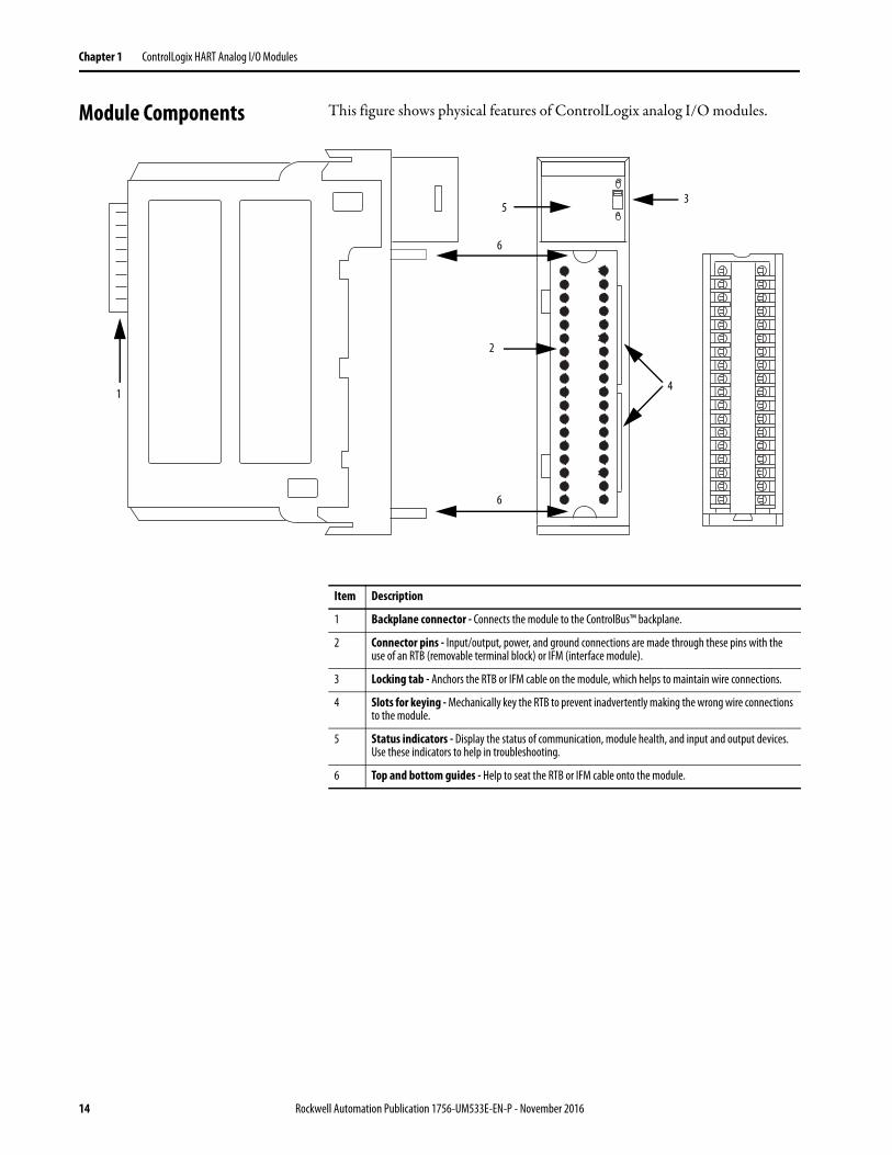
Module Components This figure shows physical features of ControlLogix analog I/O modules.
1
2
3
4
5
6
6
Item Description
1 Backplane connector - Connects the module to the ControlBus™ backplane.
2 Connector pins - Input/output, power, and ground connections are made through these pins with the use of an RTB (removable terminal block) or IFM (interface module).
3 Locking tab - Anchors the RTB or IFM cable on the module, which helps to maintain wire connections.
4 Slots for keying - Mechanically key the RTB to prevent inadvertently making the wrong wire connections to the module.
5 Status indicators - Display the status of communication, module health, and input and output devices. Use these indicators to help in troubleshooting.
6 Top and bottom guides - Help to seat the RTB or IFM cable onto the module.
14 Rockwell Automation Publication 1756-UM533E-EN-P - November 2016
ControlLogix HART Analog I/O Modules Chapter 1
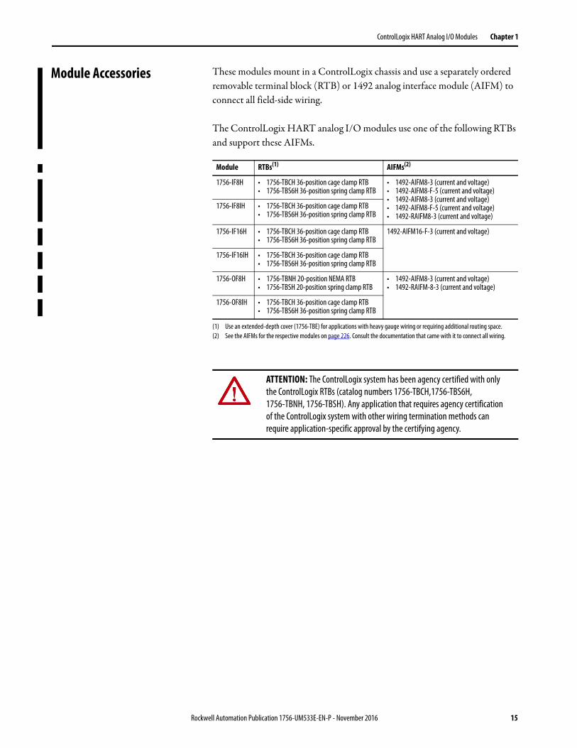
Module Accessories These modules mount in a ControlLogix chassis and use a separately ordered removable terminal block (RTB) or 1492 analog interface module (AIFM) to connect all field-side wiring.
The ControlLogix HART analog I/O modules use one of the following RTBs and support these AIFMs.
Module RTBs(1)
(1) Use an extended-depth cover (1756-TBE) for applications with heavy gauge wiring or requiring additional routing space.
AIFMs(2)
(2) See the AIFMs for the respective modules on page 226. Consult the documentation that came with it to connect all wiring.
1756-IF8H • 1756-TBCH 36-position cage clamp RTB• 1756-TBS6H 36-position spring clamp RTB
• 1492-AIFM8-3 (current and voltage)• 1492-AIFM8-F-5 (current and voltage)• 1492-AIFM8-3 (current and voltage)• 1492-AIFM8-F-5 (current and voltage)• 1492-RAIFM8-3 (current and voltage)
1756-IF8IH • 1756-TBCH 36-position cage clamp RTB• 1756-TBS6H 36-position spring clamp RTB
1756-IF16H • 1756-TBCH 36-position cage clamp RTB• 1756-TBS6H 36-position spring clamp RTB
1492-AIFM16-F-3 (current and voltage)
1756-IF16IH • 1756-TBCH 36-position cage clamp RTB• 1756-TBS6H 36-position spring clamp RTB
1756-OF8H • 1756-TBNH 20-position NEMA RTB• 1756-TBSH 20-position spring clamp RTB
• 1492-AIFM8-3 (current and voltage)• 1492-RAIFM-8-3 (current and voltage)
1756-OF8IH • 1756-TBCH 36-position cage clamp RTB• 1756-TBS6H 36-position spring clamp RTB
ATTENTION: The ControlLogix system has been agency certified with only the ControlLogix RTBs (catalog numbers 1756-TBCH,1756-TBS6H, 1756-TBNH, 1756-TBSH). Any application that requires agency certification of the ControlLogix system with other wiring termination methods can require application-specific approval by the certifying agency.
Rockwell Automation Publication 1756-UM533E-EN-P - November 2016 15
Chapter 1 ControlLogix HART Analog I/O Modules
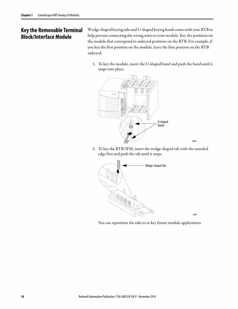
Key the Removable Terminal Block/Interface Module
Wedge-shaped keying tabs and U-shaped keying bands come with your RTB to help prevent connecting the wrong wires to your module. Key the positions on the module that correspond to unkeyed positions on the RTB. For example, if you key the first position on the module, leave the first position on the RTB unkeyed.
1. To key the module, insert the U-shaped band and push the band until it snaps into place.
2. To key the RTB/IFM, insert the wedge-shaped tab with the rounded edge first and push the tab until it stops.
You can reposition the tabs to re-key future module applications.
U-shaped Bands
20850
Wedge-shaped Tab
20851
16 Rockwell Automation Publication 1756-UM533E-EN-P - November 2016
ControlLogix HART Analog I/O Modules Chapter 1
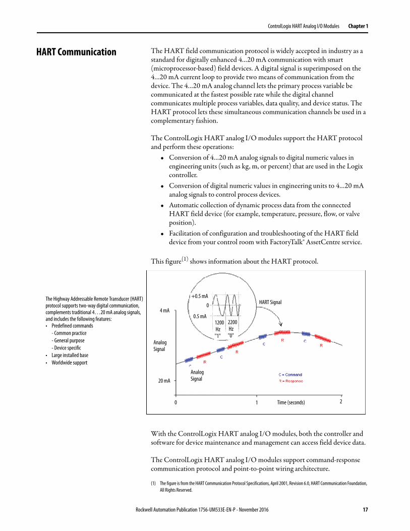
HART Communication The HART field communication protocol is widely accepted in industry as a standard for digitally enhanced 4…20 mA communication with smart (microprocessor-based) field devices. A digital signal is superimposed on the 4…20 mA current loop to provide two means of communication from the device. The 4…20 mA analog channel lets the primary process variable be communicated at the fastest possible rate while the digital channel communicates multiple process variables, data quality, and device status. The HART protocol lets these simultaneous communication channels be used in a complementary fashion.
The ControlLogix HART analog I/O modules support the HART protocol and perform these operations:
• Conversion of 4…20 mA analog signals to digital numeric values in engineering units (such as kg, m, or percent) that are used in the Logix controller.
• Conversion of digital numeric values in engineering units to 4…20 mA analog signals to control process devices.
• Automatic collection of dynamic process data from the connected HART field device (for example, temperature, pressure, flow, or valve position).
• Facilitation of configuration and troubleshooting of the HART field device from your control room with FactoryTalk® AssetCentre service.
This figure(1) shows information about the HART protocol.
With the ControlLogix HART analog I/O modules, both the controller and software for device maintenance and management can access field device data.
The ControlLogix HART analog I/O modules support command-response communication protocol and point-to-point wiring architecture.
(1) The figure is from the HART Communication Protocol Specifications, April 2001, Revision 6.0, HART Communication Foundation, All Rights Reserved.
The Highway Addressable Remote Transducer (HART) protocol supports two-way digital communication, complements traditional 4…20 mA analog signals, and includes the following features:• Predefined commands
- Common practice- General purpose - Device specific
• Large installed base• Worldwide support
Analog Signal
+0.5 mA
0.5 mA
0
1200 Hz"1"
2200 Hz"0"
Time (seconds) 2
HART Signal
0 1
Analog Signal
4 mA
20 mA
Rockwell Automation Publication 1756-UM533E-EN-P - November 2016 17
Chapter 1 ControlLogix HART Analog I/O Modules
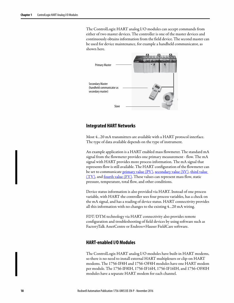
The ControlLogix HART analog I/O modules can accept commands from either of two master devices. The controller is one of the master devices and continuously obtains information from the field device. The second master can be used for device maintenance, for example a handheld communicator, as shown here.
Integrated HART Networks
Most 4…20 mA transmitters are available with a HART protocol interface. The type of data available depends on the type of instrument.
An example application is a HART enabled mass flowmeter. The standard mA signal from the flowmeter provides one primary measurement - flow. The mA signal with HART provides more process information. The mA signal that represents flow is still available. The HART configuration of the flowmeter can be set to communicate primary value (PV), secondary value (SV), third value (TV), and fourth value (FV). These values can represent mass flow, static pressure, temperature, total flow, and other conditions.
Device status information is also provided via HART. Instead of one process variable, with HART the controller sees four process variables, has a check on the mA signal, and has a reading of device status. HART connectivity provides all this information with no changes to the existing 4…20 mA wiring.
FDT/DTM technology via HART connectivity also provides remote configuration and troubleshooting of field devices by using software such as FactoryTalk AssetCentre or Endress+Hauser FieldCare software.
HART-enabled I/O Modules
The ControlLogix HART analog I/O modules have built-in HART modems, so there is no need to install external HART multiplexers or clip-on HART modems. The 1756-IF8H and 1756-OF8H modules have one HART modem per module. The 1756-IF8IH, 1756-IF16H, 1756-IF16IH, and 1756-OF8IH modules have a separate HART modem for each channel.
Primary Master
Secondary Master (handheld communicator as secondary master)
Slave
18 Rockwell Automation Publication 1756-UM533E-EN-P - November 2016
ControlLogix HART Analog I/O Modules Chapter 1
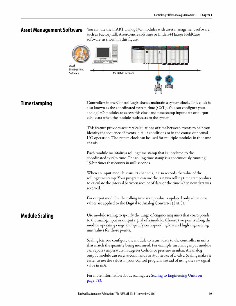
Asset Management Software You can use the HART analog I/O modules with asset management software, such as FactoryTalk AssetCentre software or Endess+Hauser FieldCare software, as shown in this figure.
Timestamping Controllers in the ControlLogix chassis maintain a system clock. This clock is also known as the coordinated system time (CST). You can configure your analog I/O modules to access this clock and time stamp input data or output echo data when the module multicasts to the system.
This feature provides accurate calculations of time between events to help you identify the sequence of events in fault conditions or in the course of normalI/O operation. The system clock can be used for multiple modules in the same chassis.
Each module maintains a rolling time stamp that is unrelated to the coordinated system time. The rolling time stamp is a continuously running 15-bit timer that counts in milliseconds.
When an input module scans its channels, it also records the value of the rolling time stamp. Your program can use the last two rolling time stamp values to calculate the interval between receipt of data or the time when new data was received.
For output modules, the rolling time stamp value is updated only when new values are applied to the Digital to Analog Converter (DAC).
Module Scaling Use module scaling to specify the range of engineering units that corresponds to the analog input or output signal of a module. Choose two points along the module operating range and specify corresponding low and high engineering unit values for those points.
Scaling lets you configure the module to return data to the controller in units that match the quantity being measured. For example, an analog input module can report temperature in degrees Celsius or pressure in mbar. An analog output module can receive commands in % of stroke of a valve. Scaling makes it easier to use the values in your control program instead of using the raw signal value in mA.
For more information about scaling, see Scaling to Engineering Units on page 153.
EtherNet/IP Network
Asset Management Software
Rockwell Automation Publication 1756-UM533E-EN-P - November 2016 19
Chapter 1 ControlLogix HART Analog I/O Modules
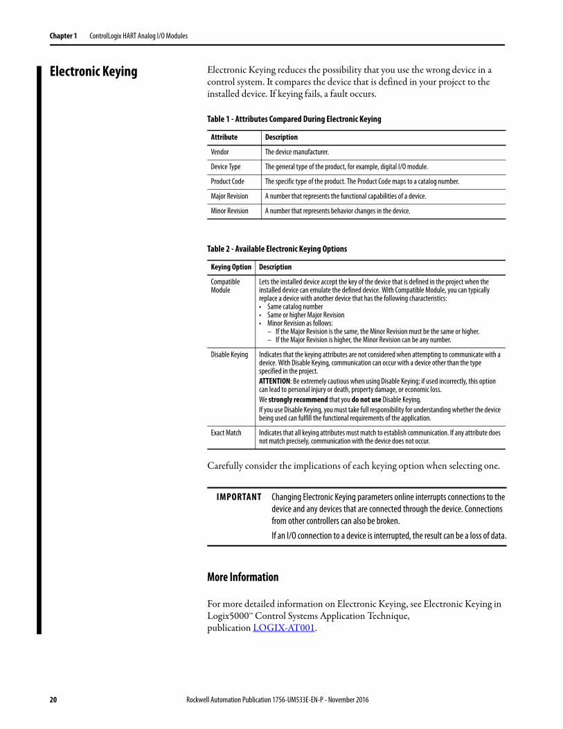
Electronic Keying Electronic Keying reduces the possibility that you use the wrong device in a control system. It compares the device that is defined in your project to the installed device. If keying fails, a fault occurs.
Carefully consider the implications of each keying option when selecting one.
More Information
For more detailed information on Electronic Keying, see Electronic Keying in Logix5000™ Control Systems Application Technique, publication LOGIX-AT001.
Table 1 - Attributes Compared During Electronic Keying
Attribute Description
Vendor The device manufacturer.
Device Type The general type of the product, for example, digital I/O module.
Product Code The specific type of the product. The Product Code maps to a catalog number.
Major Revision A number that represents the functional capabilities of a device.
Minor Revision A number that represents behavior changes in the device.
Table 2 - Available Electronic Keying Options
Keying Option Description
Compatible Module
Lets the installed device accept the key of the device that is defined in the project when the installed device can emulate the defined device. With Compatible Module, you can typically replace a device with another device that has the following characteristics: • Same catalog number• Same or higher Major Revision• Minor Revision as follows:
– If the Major Revision is the same, the Minor Revision must be the same or higher.– If the Major Revision is higher, the Minor Revision can be any number.
Disable Keying Indicates that the keying attributes are not considered when attempting to communicate with a device. With Disable Keying, communication can occur with a device other than the type specified in the project.ATTENTION: Be extremely cautious when using Disable Keying; if used incorrectly, this option can lead to personal injury or death, property damage, or economic loss. We strongly recommend that you do not use Disable Keying. If you use Disable Keying, you must take full responsibility for understanding whether the device being used can fulfill the functional requirements of the application.
Exact Match Indicates that all keying attributes must match to establish communication. If any attribute does not match precisely, communication with the device does not occur.
IMPORTANT Changing Electronic Keying parameters online interrupts connections to the device and any devices that are connected through the device. Connections from other controllers can also be broken.If an I/O connection to a device is interrupted, the result can be a loss of data.
20 Rockwell Automation Publication 1756-UM533E-EN-P - November 2016
Chapter 2
ControlLogix Module Operation
This chapter discusses these topics.
A ControlLogix® controller must own every I/O module in the ControlLogix system. The owner controller stores configuration data for every module that it owns. The owner controller can be located locally (in the same chassis) or remotely (in another chassis), relative to the position of the I/O module. The owner controller sends configuration data to the I/O module to define the behavior of the module and begin operation within the control system. Each ControlLogix I/O module must continuously maintain communication with its owner to operate normally.
Typically, each module in the system has only one owner. Input modules can have multiple owners. Output modules are limited to one owner.
With the Producer/Consumer model, ControlLogix I/O modules can produce data without a controller polling them first. The modules produce the data and any owner or listen-only controller device can consume it.
For example, an input module produces data and any number of controllers can consume the data simultaneously. This feature minimizes the need for one controller to send data to another controller.
Topic Page
Direct Connections 22
Input Module Operation 22
Input Modules in a Local Chassis 23
Input Modules in a Remote Chassis 26
Output Module Operation 28
Output Modules in a Local Chassis 28
Output Modules in a Remote Chassis 29
Listen-only Mode 30
Multiple Owners of Input Modules 31
Configuration Changes in an Input Module with Multiple Owners 32
Unicast Communication 32
Rockwell Automation Publication 1756-UM533E-EN-P - November 2016 21
Chapter 2 ControlLogix Module Operation
Direct Connections A direct connection is a real-time data transfer link between the controller and the device that occupies the slot that the configuration data references. ControlLogix analog I/O modules use direct connections only.
When an owner controller downloads module configuration data, the controller attempts to establish a direct connection to each of the modules the data references.
If a controller has configuration data that references a slot in the control system, the controller periodically checks for the presence of a module there. When presence of a module is first detected, the controller automatically sends the configuration data and one of the following events occurs:
• If the data is appropriate to the module found in the slot, a connection is made and operation begins.
• If the configuration data is not appropriate, the module rejects the data and an error code displays in the software. For example, configuration data for a module can be appropriate except for a mismatch in electronic keying that prevents normal operation. For more information about error codes, see Module Configuration Errors on page 221.
The controller maintains and monitors its connection with a module. Any break in the connection (for example, module removal under power) causes the controller to set fault status bits in the data area that is associated with the module. You can use ladder logic to monitor this data area and detect module failures.
Input Module Operation In the ControlLogix system, the owner controller does not poll analog input modules after a connection is established. The modules multicast their data periodically. Multicast frequency depends on options that are chosen during configuration and the physical location of the module in the control system.
Communication or multicasting behavior of a module varies depending upon whether the module operates in a local or remote chassis (relative to the owner controller), based on network type. The following sections detail the differences in data transfers between these setups.
22 Rockwell Automation Publication 1756-UM533E-EN-P - November 2016
ControlLogix Module Operation Chapter 2
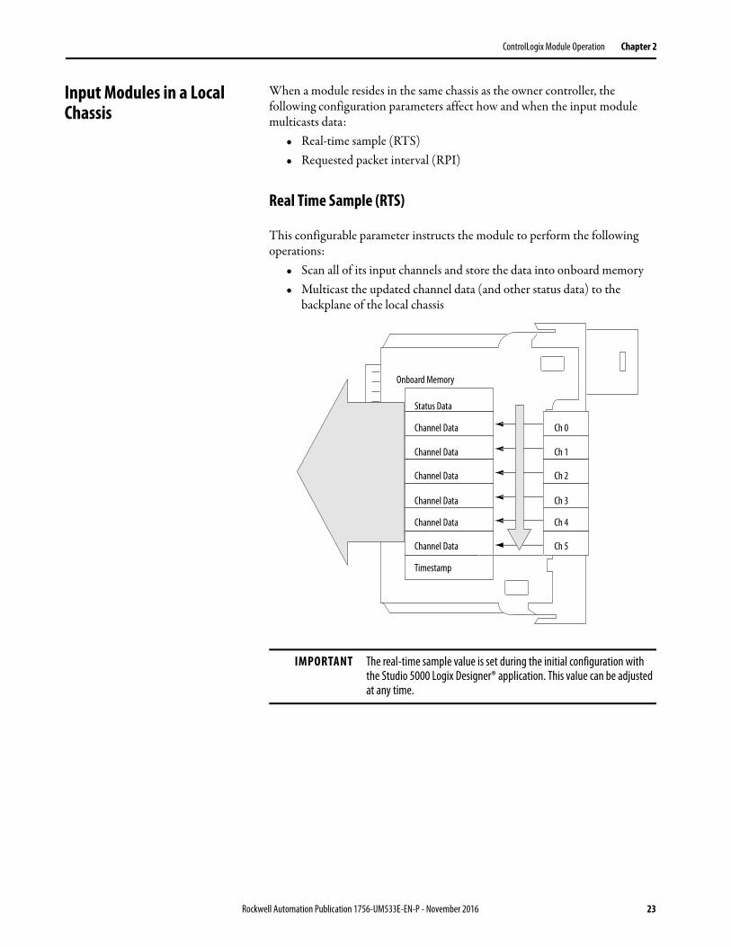
Input Modules in a Local Chassis
When a module resides in the same chassis as the owner controller, the following configuration parameters affect how and when the input module multicasts data:
• Real-time sample (RTS)• Requested packet interval (RPI)
Real Time Sample (RTS)
This configurable parameter instructs the module to perform the following operations:
• Scan all of its input channels and store the data into onboard memory• Multicast the updated channel data (and other status data) to the
backplane of the local chassis
IMPORTANT The real-time sample value is set during the initial configuration with the Studio 5000 Logix Designer® application. This value can be adjusted at any time.
Onboard Memory
Status Data
Channel Data
Channel Data
Channel Data
Channel Data
Channel Data
Channel Data
Ch 0
Ch 1
Ch 2
Ch 3
Ch 4
Ch 5
Timestamp
Rockwell Automation Publication 1756-UM533E-EN-P - November 2016 23
Chapter 2 ControlLogix Module Operation
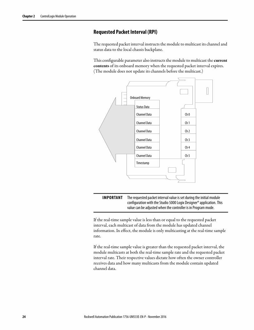
Requested Packet Interval (RPI)
The requested packet interval instructs the module to multicast its channel and status data to the local chassis backplane.
This configurable parameter also instructs the module to multicast the current contents of its onboard memory when the requested packet interval expires. (The module does not update its channels before the multicast.)
If the real-time sample value is less than or equal to the requested packet interval, each multicast of data from the module has updated channel information. In effect, the module is only multicasting at the real-time sample rate.
If the real-time sample value is greater than the requested packet interval, the module multicasts at both the real-time sample rate and the requested packet interval rate. Their respective values dictate how often the owner controller receives data and how many multicasts from the module contain updated channel data.
IMPORTANT The requested packet interval value is set during the initial module configuration with the Studio 5000 Logix Designer® application. This value can be adjusted when the controller is in Program mode.
Onboard Memory
Status Data
Channel Data
Channel Data
Channel Data
Channel Data
Channel Data
Channel Data
Ch 0
Ch 1
Ch 2
Ch 3
Ch 4
Ch 5
Timestamp
24 Rockwell Automation Publication 1756-UM533E-EN-P - November 2016
ControlLogix Module Operation Chapter 2
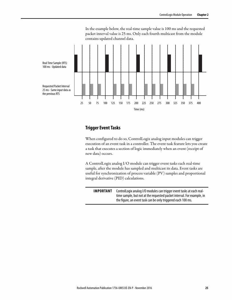
In the example below, the real-time sample value is 100 ms and the requested packet interval value is 25 ms. Only each fourth multicast from the module contains updated channel data.
Trigger Event Tasks
When configured to do so, ControlLogix analog input modules can trigger execution of an event task in a controller. The event task feature lets you create a task that executes a section of logic immediately when an event (receipt of new data) occurs.
A ControlLogix analog I/O module can trigger event tasks each real-time sample, after the module has sampled and multicast its data. Event tasks are useful for synchronization of process variable (PV) samples and proportional integral derivative (PID) calculations.
Real Time Sample (RTS) 100 ms - Updated data
Requested Packet Interval25 ms - Same input data as the previous RTS
25 50 75 100 125 150 175 200 225 250 275 300 325 350 375 400
Time (ms)
IMPORTANT ControlLogix analog I/O modules can trigger event tasks at each real-time sample, but not at the requested packet interval. For example, in the figure, an event task can be only triggered each 100 ms.
Rockwell Automation Publication 1756-UM533E-EN-P - November 2016 25
Chapter 2 ControlLogix Module Operation
Input Modules in a Remote Chassis
For an input module in a remote chassis, the roles of requested packet interval and real-time sample behavior change slightly regarding data communication to the owner controller. This change depends on what network type is used to communicate with the modules.
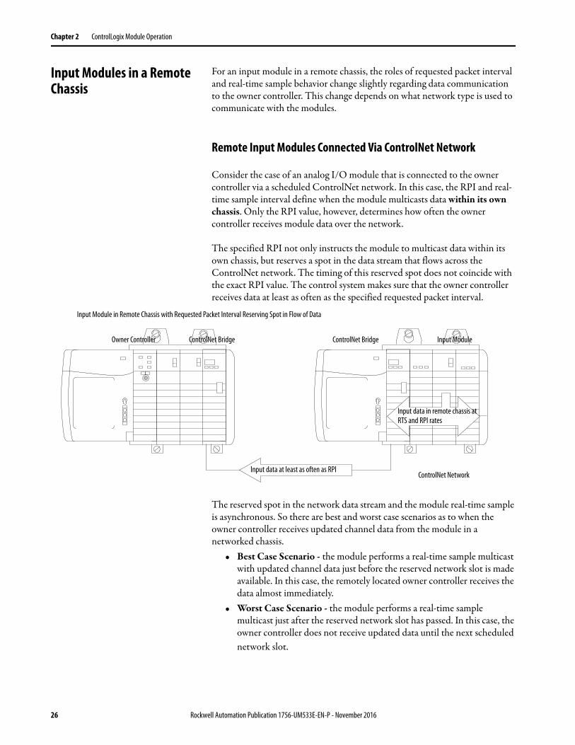
Remote Input Modules Connected Via ControlNet Network
Consider the case of an analog I/O module that is connected to the owner controller via a scheduled ControlNet network. In this case, the RPI and real-time sample interval define when the module multicasts data within its own chassis. Only the RPI value, however, determines how often the owner controller receives module data over the network.
The specified RPI not only instructs the module to multicast data within its own chassis, but reserves a spot in the data stream that flows across the ControlNet network. The timing of this reserved spot does not coincide with the exact RPI value. The control system makes sure that the owner controller receives data at least as often as the specified requested packet interval.
The reserved spot in the network data stream and the module real-time sample is asynchronous. So there are best and worst case scenarios as to when the owner controller receives updated channel data from the module in a networked chassis.
• Best Case Scenario - the module performs a real-time sample multicast with updated channel data just before the reserved network slot is made available. In this case, the remotely located owner controller receives the data almost immediately.
• Worst Case Scenario - the module performs a real-time sample multicast just after the reserved network slot has passed. In this case, the owner controller does not receive updated data until the next scheduled network slot.
ControlNet NetworkInput data at least as often as RPI
Input data in remote chassis at RTS and RPI rates
Owner Controller ControlNet Bridge ControlNet Bridge Input Module
Input Module in Remote Chassis with Requested Packet Interval Reserving Spot in Flow of Data
26 Rockwell Automation Publication 1756-UM533E-EN-P - November 2016
ControlLogix Module Operation Chapter 2
RPI, not real-time sample interval, dictates when module data is sent over the network. Therefore, we recommend that you set the RPI less than or equal to the real-time sample interval. This setting helps make sure that the owner controller receives updated channel data with each receipt of data.
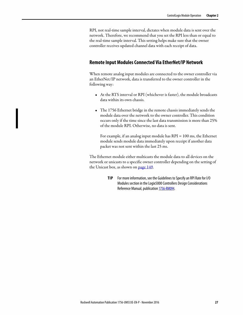
Remote Input Modules Connected Via EtherNet/IP Network
When remote analog input modules are connected to the owner controller via an EtherNet/IP network, data is transferred to the owner controller in the following way:
• At the RTS interval or RPI (whichever is faster), the module broadcasts data within its own chassis.
• The 1756 Ethernet bridge in the remote chassis immediately sends the module data over the network to the owner controller. This condition occurs only if the time since the last data transmission is more than 25% of the module RPI. Otherwise, no data is sent.
For example, if an analog input module has RPI = 100 ms, the Ethernet module sends module data immediately upon receipt if another data packet was not sent within the last 25 ms.
The Ethernet module either multicasts the module data to all devices on the network or unicasts to a specific owner controller depending on the setting of the Unicast box, as shown on page 149.
TIP For more information, see the Guidelines to Specify an RPI Rate for I/O Modules section in the Logix5000 Controllers Design Considerations Reference Manual, publication 1756-RM094.
Rockwell Automation Publication 1756-UM533E-EN-P - November 2016 27
Chapter 2 ControlLogix Module Operation
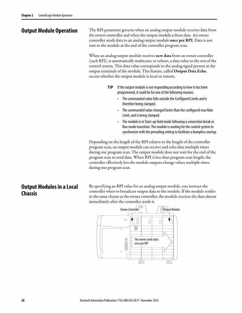
Output Module Operation The RPI parameter governs when an analog output module receives data from the owner controller and when the output module echoes data. An owner controller sends data to an analog output module once per RPI. Data is not sent to the module at the end of the controller program scan.
When an analog output module receives new data from an owner controller (each RPI), it automatically multicasts, or echoes, a data value to the rest of the control system. This data value corresponds to the analog signal present at the output terminals of the module. This feature, called Output Data Echo, occurs whether the output module is local or remote.
Depending on the length of the RPI relative to the length of the controller program scan, an output module can receive and echo data multiple times during one program scan. The output module does not wait for the end of the program scan to send data. When RPI is less than program scan length, the controller effectively lets the module outputs change values multiple times during one program scan.
Output Modules in a Local Chassis
By specifying an RPI value for an analog output module, you instruct the controller when to broadcast output data to the module. If the module resides in the same chassis as the owner controller, the module receives the data almost immediately after the controller sends it.
TIP If the output module is not responding according to how it has been programmed, it could be for one of the following reasons:• The commanded value falls outside the Configured Limits and is
therefore being clamped.• The commanded value changed faster than the configured max Rate
Limit, and is being clamped.• The module is in Start-up Hold mode following a connection break or
Run mode transition. The module is waiting for the control system to synchronize with the prevailing setting to facilitate a bumpless startup.
The owner sends dataonce per RPI
Owner Controller Output Module
28 Rockwell Automation Publication 1756-UM533E-EN-P - November 2016
ControlLogix Module Operation Chapter 2
Output Modules in a Remote Chassis
For output modules in remote chassis, the role of RPI in getting data from the owner controller changes slightly, depending on the network.
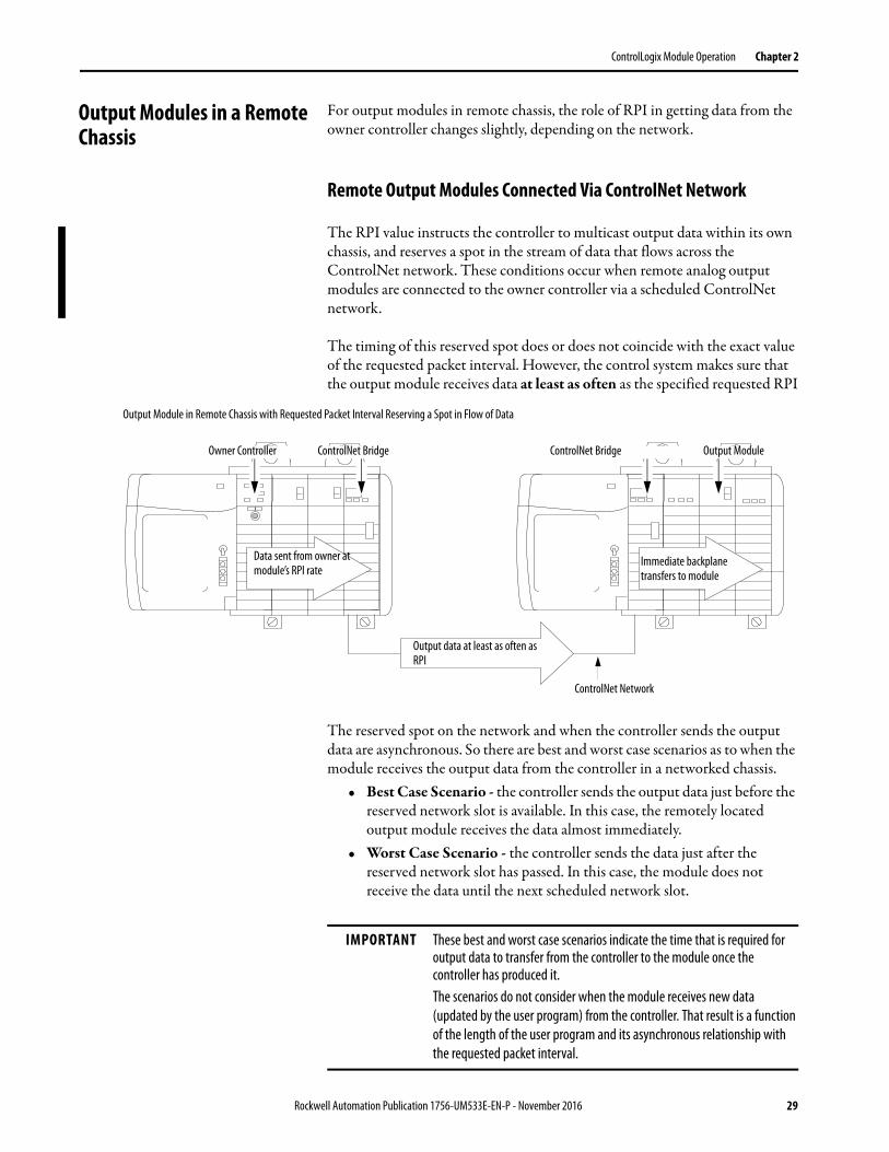
Remote Output Modules Connected Via ControlNet Network
The RPI value instructs the controller to multicast output data within its own chassis, and reserves a spot in the stream of data that flows across the ControlNet network. These conditions occur when remote analog output modules are connected to the owner controller via a scheduled ControlNet network.
The timing of this reserved spot does or does not coincide with the exact value of the requested packet interval. However, the control system makes sure that the output module receives data at least as often as the specified requested RPI.
The reserved spot on the network and when the controller sends the output data are asynchronous. So there are best and worst case scenarios as to when the module receives the output data from the controller in a networked chassis.
• Best Case Scenario - the controller sends the output data just before the reserved network slot is available. In this case, the remotely located output module receives the data almost immediately.
• Worst Case Scenario - the controller sends the data just after the reserved network slot has passed. In this case, the module does not receive the data until the next scheduled network slot.
ControlNet Network
Output data at least as often as RPI
Immediate backplane transfers to module
Data sent from owner at module’s RPI rate
Owner Controller ControlNet Bridge ControlNet Bridge Output Module
Output Module in Remote Chassis with Requested Packet Interval Reserving a Spot in Flow of Data
IMPORTANT These best and worst case scenarios indicate the time that is required for output data to transfer from the controller to the module once the controller has produced it.The scenarios do not consider when the module receives new data (updated by the user program) from the controller. That result is a function of the length of the user program and its asynchronous relationship with the requested packet interval.
Rockwell Automation Publication 1756-UM533E-EN-P - November 2016 29
Chapter 2 ControlLogix Module Operation
Remote Output Modules Connected Via EtherNet/IP Network
When remote analog output modules are connected to the owner controller via an EtherNet/IP network, the controller multicasts data in the following way:
• At the RPI, the owner controller multicasts data within its own chassis.
• The EtherNet/IP communication module in the local chassis immediately sends the data over the network to the analog output module. This condition occurs as long as it has not sent data within a time frame that is 1/4 the value of the requested packet interval of the analog module.
Listen-only Mode Any controller in the system can listen to the data from any I/O module (that is, input data or ‘echoed’ output data) even if the controller does not own the module. In other words, the controller does not have to own the configuration data of a module to listen to it.
During the I/O configuration process, you can specify a ‘Listen-Only’ mode in the Connection box of the Module Definition section on the Module Properties dialog box. See page 147 for more details.
In ‘Listen-Only’ mode, the controller and module establish communication without the controller sending any configuration data. Another controller owns the module being listened to.
IMPORTANT If a controller has a ‘Listen-Only’ connection to a module, the module cannot use the Unicast option for any connections over the EtherNet/IP network. See the Unicast box on page 149.The ‘Listen-Only’ controller continues to receive multicast data from the I/O module as long as a connection between an owner controller and the I/O module is maintained.If the connection between all owner controllers and the module is broken, the module stops multicasting data and connections to all listening controllers are also broken.
30 Rockwell Automation Publication 1756-UM533E-EN-P - November 2016
ControlLogix Module Operation Chapter 2
Multiple Owners of Input Modules
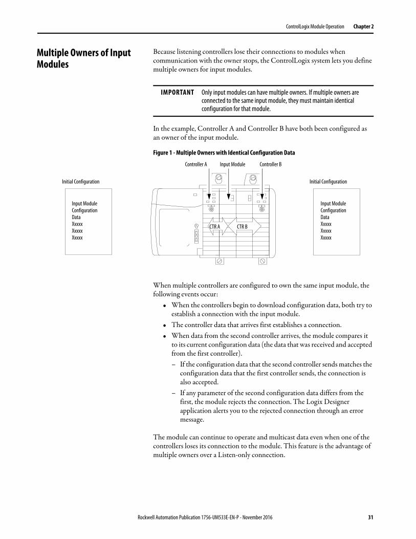
Because listening controllers lose their connections to modules when communication with the owner stops, the ControlLogix system lets you define multiple owners for input modules.
In the example, Controller A and Controller B have both been configured as an owner of the input module.
Figure 1 - Multiple Owners with Identical Configuration Data
When multiple controllers are configured to own the same input module, the following events occur:
• When the controllers begin to download configuration data, both try to establish a connection with the input module.
• The controller data that arrives first establishes a connection.• When data from the second controller arrives, the module compares it
to its current configuration data (the data that was received and accepted from the first controller).– If the configuration data that the second controller sends matches the
configuration data that the first controller sends, the connection is also accepted.
– If any parameter of the second configuration data differs from the first, the module rejects the connection. The Logix Designer application alerts you to the rejected connection through an error message.
The module can continue to operate and multicast data even when one of the controllers loses its connection to the module. This feature is the advantage of multiple owners over a Listen-only connection.
IMPORTANT Only input modules can have multiple owners. If multiple owners are connected to the same input module, they must maintain identical configuration for that module.
Input Module Configuration DataXxxxxXxxxxXxxxx
Input Module Configuration DataXxxxxXxxxxXxxxx
Initial Configuration Initial Configuration
Controller A Controller BInput Module
CTR A CTR B
Rockwell Automation Publication 1756-UM533E-EN-P - November 2016 31
Chapter 2 ControlLogix Module Operation
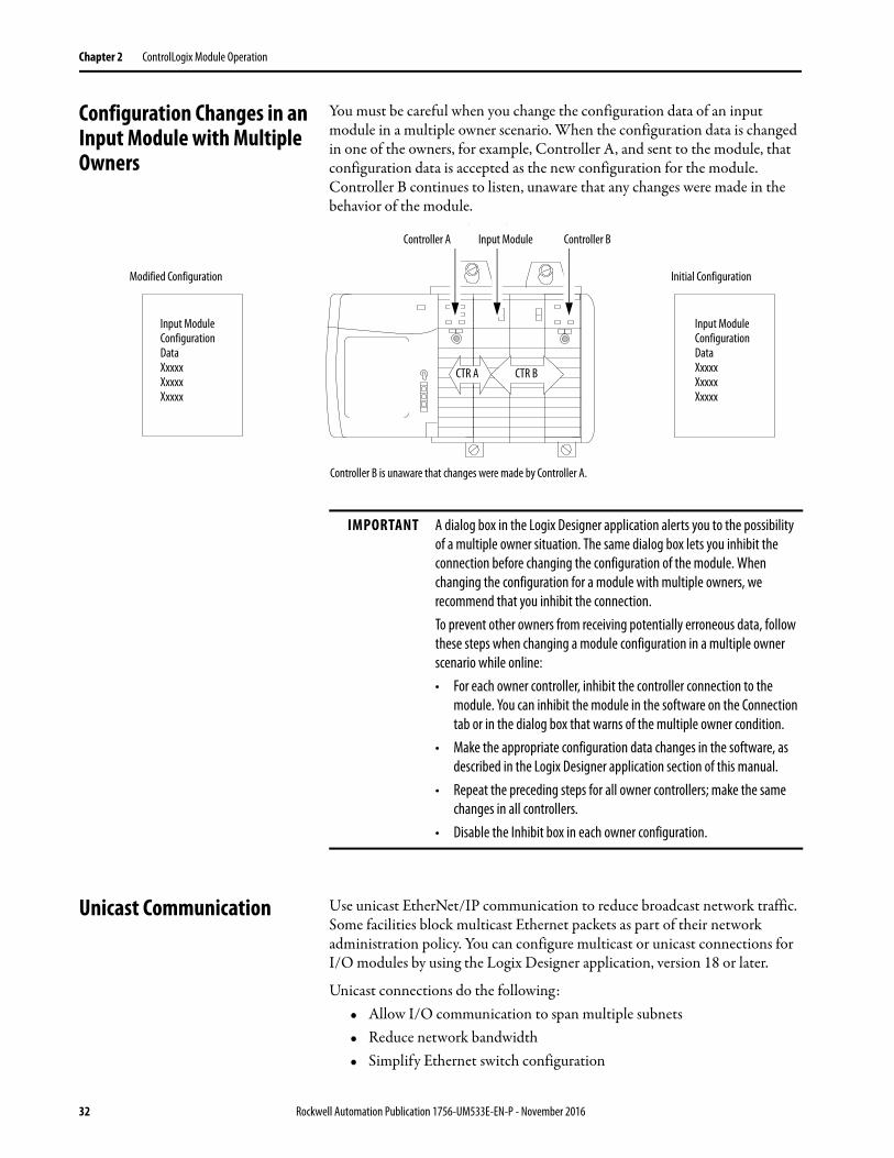
Configuration Changes in an Input Module with Multiple Owners
You must be careful when you change the configuration data of an input module in a multiple owner scenario. When the configuration data is changed in one of the owners, for example, Controller A, and sent to the module, that configuration data is accepted as the new configuration for the module. Controller B continues to listen, unaware that any changes were made in the behavior of the module.
Unicast Communication Use unicast EtherNet/IP communication to reduce broadcast network traffic. Some facilities block multicast Ethernet packets as part of their network administration policy. You can configure multicast or unicast connections for I/O modules by using the Logix Designer application, version 18 or later.
Unicast connections do the following:• Allow I/O communication to span multiple subnets• Reduce network bandwidth• Simplify Ethernet switch configuration
Input Module Configuration DataXxxxxXxxxxXxxxx
Input Module Configuration DataXxxxxXxxxxXxxxx
Modified Configuration Initial Configuration
Controller A Controller BInput Module
CTR A CTR B
Controller B is unaware that changes were made by Controller A.
g g
IMPORTANT A dialog box in the Logix Designer application alerts you to the possibility of a multiple owner situation. The same dialog box lets you inhibit the connection before changing the configuration of the module. When changing the configuration for a module with multiple owners, we recommend that you inhibit the connection.To prevent other owners from receiving potentially erroneous data, follow these steps when changing a module configuration in a multiple owner scenario while online:• For each owner controller, inhibit the controller connection to the
module. You can inhibit the module in the software on the Connection tab or in the dialog box that warns of the multiple owner condition.
• Make the appropriate configuration data changes in the software, as described in the Logix Designer application section of this manual.
• Repeat the preceding steps for all owner controllers; make the same changes in all controllers.
• Disable the Inhibit box in each owner configuration.
32 Rockwell Automation Publication 1756-UM533E-EN-P - November 2016
Chapter 3
1756-IF8H HART Analog Input Module
This chapter discusses these topics.
Module Features The 1756-IF8H module has the following features:• Choice of three data formats
• Analog only• Analog and HART PV• Analog and HART by channel)
• Multiple current and voltage input ranges• Module filter• Real-time sampling• Underrange and overrange detection• Process alarms• Rate alarm• Wire-off detection• Highway addressable remote transducer (HART) communication
Topic Page
Module Features 33
Wire the Module 40
Circuit Diagrams 42
1756-IF8H Module Fault and Status Reporting 43
1756-IF8H Tag Definitions 46
IMPORTANT The Analog and HART by Channel data type is available only for 1756-IF8H firmware revision 2.001 or later.
Rockwell Automation Publication 1756-UM533E-EN-P - November 2016 33
Chapter 3 1756-IF8H HART Analog Input Module
Data Formats
Data format determines which values are included in the Input tag of the module and the features that are available to your application. Select the data format on the General tab in the Studio 5000 Logix Designer® application. The following data formats are available for the 1756-IF8H module.
Choose Analog and HART PV if you prefer the members of the tag to be arranged similar to non-HART analog input modules. The analog values for all channels are grouped near the end of the tag. This option makes it easy to view all eight analog values at once.
Choose Analog and HART by Channel if you prefer Status, Analog Value, and Device Status for each channel to be together in the tag. This arrangement makes it easier to view all data that is related to one field device.
Input Ranges
You can select from a series of operational ranges for each channel on the module. The range designates the minimum and maximum signals that are detectable by the module. Possible ranges include the following:
• -10…10V• 0…5V• 0…10V• 0…20 mA• 4…20 mA (HART instruments use this range.)
Format Description
Analog signal values
Analog status
HART secondary process variables and device health
HART and Analog data for each channel are grouped in tag
Analog Only X X
Analog and HART PV X X X
Analog and HART by Channel(1)
(1) Available only for 1756-IF8H firmware revision 2.1. or later
X X X X
34 Rockwell Automation Publication 1756-UM533E-EN-P - November 2016
1756-IF8H HART Analog Input Module Chapter 3
Module Filter
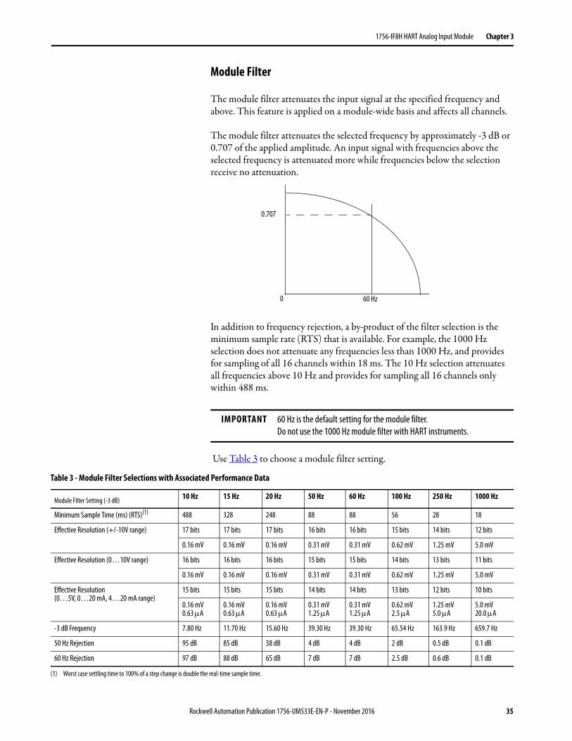
The module filter attenuates the input signal at the specified frequency and above. This feature is applied on a module-wide basis and affects all channels.
The module filter attenuates the selected frequency by approximately -3 dB or 0.707 of the applied amplitude. An input signal with frequencies above the selected frequency is attenuated more while frequencies below the selection receive no attenuation.
In addition to frequency rejection, a by-product of the filter selection is the minimum sample rate (RTS) that is available. For example, the 1000 Hz selection does not attenuate any frequencies less than 1000 Hz, and provides for sampling of all 16 channels within 18 ms. The 10 Hz selection attenuates all frequencies above 10 Hz and provides for sampling all 16 channels only within 488 ms.
Use Table 3 to choose a module filter setting.
IMPORTANT 60 Hz is the default setting for the module filter. Do not use the 1000 Hz module filter with HART instruments.
0.707
60 Hz0
Table 3 - Module Filter Selections with Associated Performance Data
Module Filter Setting (-3 dB) 10 Hz 15 Hz 20 Hz 50 Hz 60 Hz 100 Hz 250 Hz 1000 Hz
Minimum Sample Time (ms) (RTS)(1) 488 328 248 88 88 56 28 18
Effective Resolution (+/-10V range) 17 bits 17 bits 17 bits 16 bits 16 bits 15 bits 14 bits 12 bits
0.16 mV 0.16 mV 0.16 mV 0.31 mV 0.31 mV 0.62 mV 1.25 mV 5.0 mV
Effective Resolution (0…10V range) 16 bits 16 bits 16 bits 15 bits 15 bits 14 bits 13 bits 11 bits
0.16 mV 0.16 mV 0.16 mV 0.31 mV 0.31 mV 0.62 mV 1.25 mV 5.0 mV
Effective Resolution (0…5V, 0…20 mA, 4…20 mA range)
15 bits 15 bits 15 bits 14 bits 14 bits 13 bits 12 bits 10 bits
0.16 mV0.63 A
0.16 mV0.63 A
0.16 mV0.63 A
0.31 mV1.25 A
0.31 mV1.25 A
0.62 mV2.5 A
1.25 mV5.0 A
5.0 mV20.0 A
-3 dB Frequency 7.80 Hz 11.70 Hz 15.60 Hz 39.30 Hz 39.30 Hz 65.54 Hz 163.9 Hz 659.7 Hz
50 Hz Rejection 95 dB 85 dB 38 dB 4 dB 4 dB 2 dB 0.5 dB 0.1 dB
60 Hz Rejection 97 dB 88 dB 65 dB 7 dB 7 dB 2.5 dB 0.6 dB 0.1 dB
(1) Worst case settling time to 100% of a step change is double the real-time sample time.
Rockwell Automation Publication 1756-UM533E-EN-P - November 2016 35
Chapter 3 1756-IF8H HART Analog Input Module
Real-time Sampling
This parameter instructs the module how often to scan its input channels and obtain all available data. After the channels are scanned, the module multicasts that data. This feature is applied on a module-wide basis.
During module configuration, you specify a real-time sampling (RTS) period and a requested packet interval (RPI) period. Both of these features instruct the module to multicast data, but only the RTS feature instructs the module to scan its channels before multicasting.
For more RTS information, see Real Time Sample (RTS) on page 23.
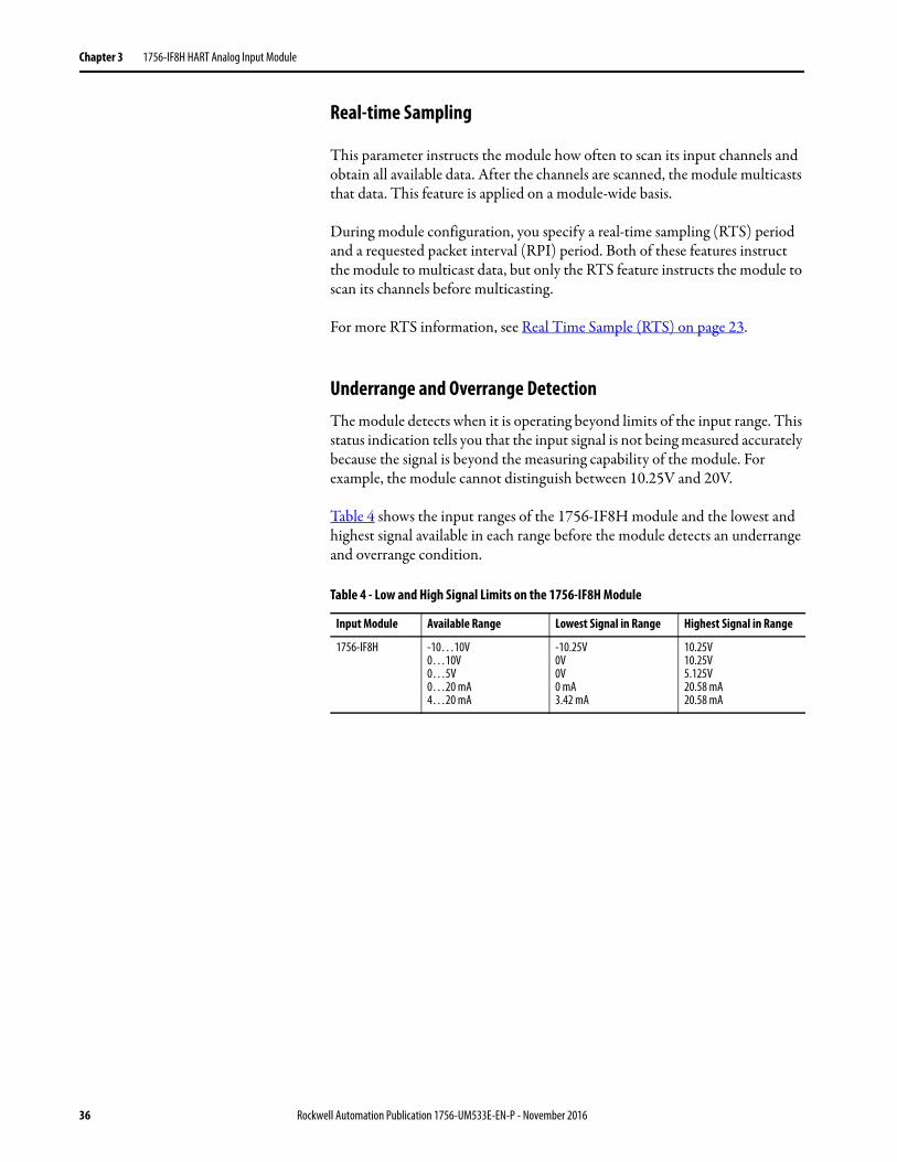
Underrange and Overrange DetectionThe module detects when it is operating beyond limits of the input range. This status indication tells you that the input signal is not being measured accurately because the signal is beyond the measuring capability of the module. For example, the module cannot distinguish between 10.25V and 20V.
Table 4 shows the input ranges of the 1756-IF8H module and the lowest and highest signal available in each range before the module detects an underrange and overrange condition.
Table 4 - Low and High Signal Limits on the 1756-IF8H Module
Input Module Available Range Lowest Signal in Range Highest Signal in Range
1756-IF8H -10…10V0…10V0…5V0…20 mA4…20 mA
-10.25V0V0V0 mA3.42 mA
10.25V10.25V5.125V20.58 mA20.58 mA
36 Rockwell Automation Publication 1756-UM533E-EN-P - November 2016
1756-IF8H HART Analog Input Module Chapter 3
Digital Filter
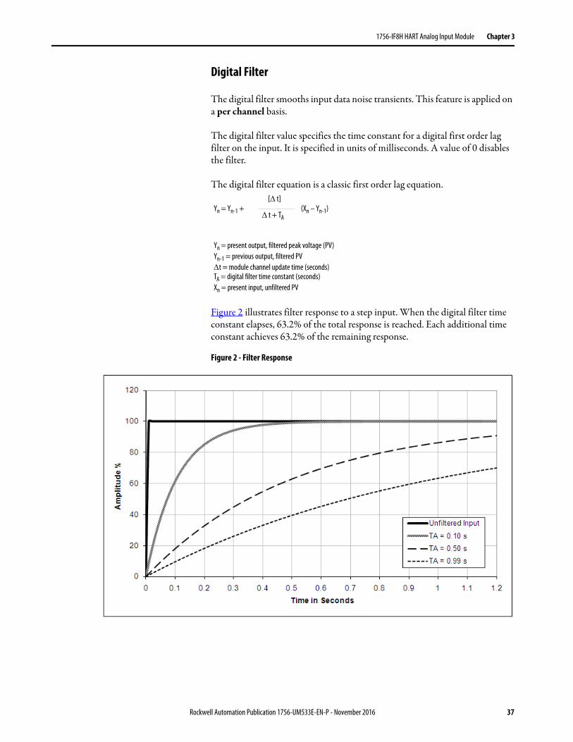
The digital filter smooths input data noise transients. This feature is applied on a per channel basis.
The digital filter value specifies the time constant for a digital first order lag filter on the input. It is specified in units of milliseconds. A value of 0 disables the filter.
The digital filter equation is a classic first order lag equation.
Figure 2 illustrates filter response to a step input. When the digital filter time constant elapses, 63.2% of the total response is reached. Each additional time constant achieves 63.2% of the remaining response.
Figure 2 - Filter Response
Yn = Yn-1 + (Xn – Yn-1)[ t]
t + TA
Yn = present output, filtered peak voltage (PV)Yn-1 = previous output, filtered PVt = module channel update time (seconds)TA = digital filter time constant (seconds)Xn = present input, unfiltered PV
Rockwell Automation Publication 1756-UM533E-EN-P - November 2016 37
Chapter 3 1756-IF8H HART Analog Input Module
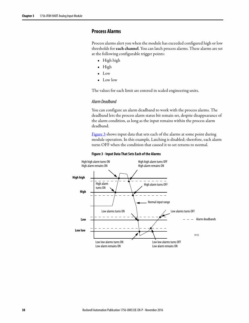
Process Alarms
Process alarms alert you when the module has exceeded configured high or low thresholds for each channel. You can latch process alarms. These alarms are set at the following configurable trigger points:
• High high• High• Low• Low low
The values for each limit are entered in scaled engineering units.
Alarm Deadband
You can configure an alarm deadband to work with the process alarms. The deadband lets the process alarm status bit remain set, despite disappearance of the alarm condition, as long as the input remains within the process alarm deadband.
Figure 3 shows input data that sets each of the alarms at some point during module operation. In this example, Latching is disabled; therefore, each alarm turns OFF when the condition that caused it to set returns to normal.
Figure 3 - Input Data That Sets Each of the Alarms
43153
High high
Low low
Low
High
Alarm deadbands
High high alarm turns OFFHigh alarm remains ON
High high alarm turns ONHigh alarm remains ON
Normal input range
Low low alarms turns OFFLow alarm remains ON
High alarm turns OFF
Low low alarms turns ONLow alarm remains ON
Low alarms turns OFFLow alarms turns ON
High alarm turns ON
38 Rockwell Automation Publication 1756-UM533E-EN-P - November 2016
1756-IF8H HART Analog Input Module Chapter 3
Rate Alarm
The value for the Rate Alarm Limit is entered in scaled engineering units per second. The rate alarm triggers if the rate of change between input samples for each channel exceeds the specified rate-alarm trigger point for that channel. Rate Alarm uses the signal value after filtering by the Module Filter and before the Digital Filter is applied.
Wire-off Detection
The 1756-IF8H modules alert you when a signal wire is disconnected from one of its channels or the RTB is removed from the module. When a wire-off condition occurs for this module, two events occur:
• Input data for that channel changes to a specific scaled value.
• A fault bit is set in the input tag, which can indicate the presence of a wire-off condition.
Because 1756-IF8H modules can be applied in voltage or current applications, differences exist as to how a wire-off condition is detected in each application.
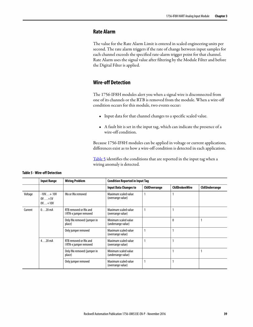
Table 5 identifies the conditions that are reported in the input tag when a wiring anomaly is detected.
Table 5 - Wire-off Detection
Input Range Wiring Problem Condition Reported in Input Tag
Input Data Changes to ChXOverrange ChXBrokenWire ChXUnderrange
Voltage -10V…+ 10V0V …+5V0V…+10V
INx or INx removed Maximum scaled value (overrange value)
1 1
Current 0…20 mA RTB removed or INx and I RTN-x jumper removed
Maximum scaled value (overrange value)
1 1
Only INx removed (jumper in place)
Minimum scaled value (underrange value)
0 1
Only jumper removed Maximum scaled value (overrange value)
1 1
4…20 mA RTB removed or INx and I RTN-x jumper removed
Maximum scaled value (overrange value)
1 1
Only INx removed (jumper in place)
Minimum scaled value (underrange value)
1 1
Only jumper removed Maximum scaled value (overrange value)
1 1
Rockwell Automation Publication 1756-UM533E-EN-P - November 2016 39
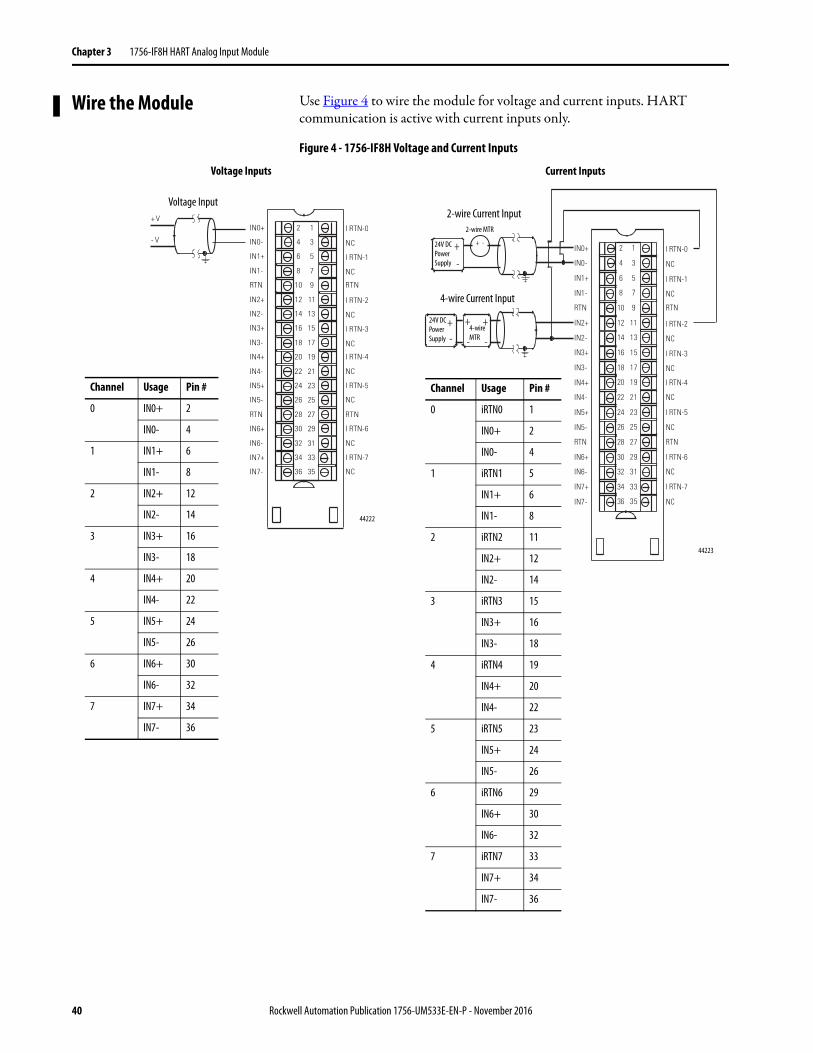
Chapter 3 1756-IF8H HART Analog Input Module
Wire the Module Use Figure 4 to wire the module for voltage and current inputs. HART communication is active with current inputs only.
Figure 4 - 1756-IF8H Voltage and Current Inputs
RTN
IN4+
IN4-
IN5+
IN5-
RTN
IN6+
IN6-
IN7+
IN7-
IN0+
IN0-
IN1+
IN1-
IN2+
IN2-
IN3+
IN3-
I RTN-0
NC
I RTN-1
NC
I RTN-2
NC
I RTN-3
NC
RTN
I RTN-4
NC
I RTN-5
NC
RTN
I RTN-6
NC
I RTN-7
NC
2
4
6
8
10
12
14
16
18
20
22
24
26
28
30
32
34
36
1
3
5
7
9
11
13
15
17
19
21
23
25
27
29
31
33
35
+ V
- V
44222
Channel Usage Pin #
0 IN0+ 2
IN0- 4
1 IN1+ 6
IN1- 8
2 IN2+ 12
IN2- 14
3 IN3+ 16
IN3- 18
4 IN4+ 20
IN4- 22
5 IN5+ 24
IN5- 26
6 IN6+ 30
IN6- 32
7 IN7+ 34
IN7- 36
Voltage Inputs Current Inputs
RTN
IN4+
IN4-
IN5+
IN5-
RTN
IN6+
IN6-
IN7+
IN7-
IN0+
IN0-
IN1+
IN1-
IN2+
IN2-
IN3+
IN3-
I RTN-0
NC
I RTN-1
NC
I RTN-2
NC
I RTN-3
NC
RTN
I RTN-4
NC
I RTN-5
NC
RTN
I RTN-6
NC
I RTN-7
NC
2
4
6
8
10
12
14
16
18
20
22
24
26
28
30
32
34
36
1
3
5
7
9
11
13
15
17
19
21
23
25
27
29
31
33
35
+-
+-
+ +
- -
+ -
44223
Channel Usage Pin #
0 iRTN0 1
IN0+ 2
IN0- 4
1 iRTN1 5
IN1+ 6
IN1- 8
2 iRTN2 11
IN2+ 12
IN2- 14
3 iRTN3 15
IN3+ 16
IN3- 18
4 iRTN4 19
IN4+ 20
IN4- 22
5 iRTN5 23
IN5+ 24
IN5- 26
6 iRTN6 29
IN6+ 30
IN6- 32
7 iRTN7 33
IN7+ 34
IN7- 36
Voltage Input2-wire Current Input
4-wire Current Input
24V DC Power Supply
24V DC Power Supply
4-wire MTR
2-wire MTR
40 Rockwell Automation Publication 1756-UM533E-EN-P - November 2016
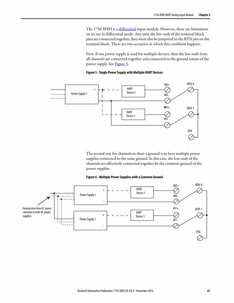
1756-IF8H HART Analog Input Module Chapter 3
The 1756-IF8H is a differential input module. However, there are limitations on its use in differential mode. Any time the low ends of the terminal block pins are connected together, they must also be jumpered to the RTN pin on the terminal block. There are two scenarios in which this condition happens.
First, if one power supply is used for multiple devices, then the low ends from all channels are connected together and connected to the ground return of the power supply. See Figure 5.
Figure 5 - Single Power Supply with Multiple HART Devices
The second way for channels to share a ground is to have multiple power supplies connected to the same ground. In this case, the low ends of the channels are effectively connected together by the common ground of the power supplies.
Figure 6 - Multiple Power Supplies with a Common Ground
HART Device 1
HART Device 1
Power Supply 1
IN0+
IN0-
IN1+
IN1-
IRTN-0
IRTN-1
RTN
+
-
IN1+
Ground wire from AC source common to both DC power supplies
HART Device 1
HART Device 1
IN0+
IN0-
IN1-
IN1+
IRTN-0
IRTN-1
RTN
Power Supply 1+
-
Power Supply 1+
-
Rockwell Automation Publication 1756-UM533E-EN-P - November 2016 41
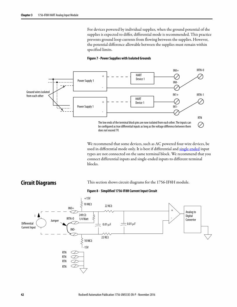
Chapter 3 1756-IF8H HART Analog Input Module
For devices powered by individual supplies, when the ground potential of the supplies is expected to differ, differential mode is recommended. This practice prevents ground loop currents from flowing between the supplies. However, the potential difference allowable between the supplies must remain within specified limits.
Figure 7 - Power Supplies with Isolated Grounds
We recommend that some devices, such as AC powered four-wire devices, be used in differential mode only. It is best if differential and single-ended input types are not connected on the same terminal block. We recommend that you connect differential inputs and single-ended inputs to different terminal blocks.
Circuit Diagrams This section shows circuit diagrams for the 1756-IF8H module.
Figure 8 - Simplified 1756-IF8H Current Input Circuit
The low ends of the terminal block pins are now isolated from each other. The inputs can be configured as true differential inputs as long as the voltage difference between them does not exceed 7V.
Power Supply 1+
-
Power Supply 1+
-
HART Device 1
HART Device 1
IN0+
IN0-
IN1-
IN1+
IRTN-0
IRTN-1
RTN
Ground wires isolated from each other
0.01 F
Analog to Digital Converter
22 K
10 M
RTNRTNRTN
RTN
-15V
Jumper
+
-
0.01 F
22 K
10 M
249 1/4 Watt
INO+
IRTN-O
INO-
+15V
Differential Current Input
i
42 Rockwell Automation Publication 1756-UM533E-EN-P - November 2016
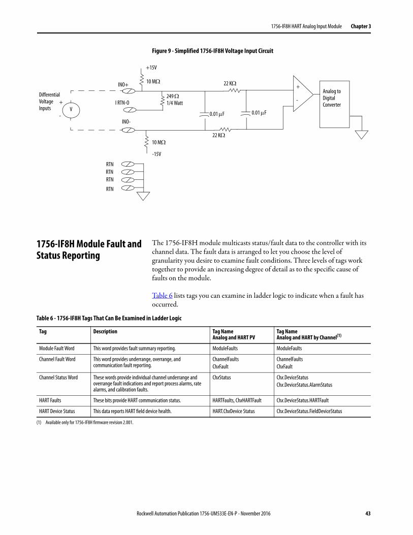
1756-IF8H HART Analog Input Module Chapter 3
Figure 9 - Simplified 1756-IF8H Voltage Input Circuit
1756-IF8H Module Fault and Status Reporting
The 1756-IF8H module multicasts status/fault data to the controller with its channel data. The fault data is arranged to let you choose the level of granularity you desire to examine fault conditions. Three levels of tags work together to provide an increasing degree of detail as to the specific cause of faults on the module.
Table 6 lists tags you can examine in ladder logic to indicate when a fault has occurred.
0.01 F
Analog to Digital Converter
22 K10 M
-15V
+
- 0.01 F
22 K10 M
249 1/4 Watt
INO+
I RTN-O
INO-
+15V
Differential Voltage Inputs V
+
-
RTNRTNRTN
RTN
Table 6 - 1756-IF8H Tags That Can Be Examined in Ladder Logic
Tag Description Tag NameAnalog and HART PV
Tag NameAnalog and HART by Channel(1)
Module Fault Word This word provides fault summary reporting. ModuleFaults ModuleFaults
Channel Fault Word This word provides underrange, overrange, and communication fault reporting.
ChannelFaultsChxFault
ChannelFaultsChxFault
Channel Status Word These words provide individual channel underrange and overrange fault indications and report process alarms, rate alarms, and calibration faults.
ChxStatus Chx.DeviceStatusChx.DeviceStatus.AlarmStatus
HART Faults These bits provide HART communication status. HARTFaults, ChxHARTFault Chx.DeviceStatus.HARTFault
HART Device Status This data reports HART field device health. HART.ChxDevice Status Chx.DeviceStatus.FieldDeviceStatus
(1) Available only for 1756-IF8H firmware revision 2.001.
Rockwell Automation Publication 1756-UM533E-EN-P - November 2016 43
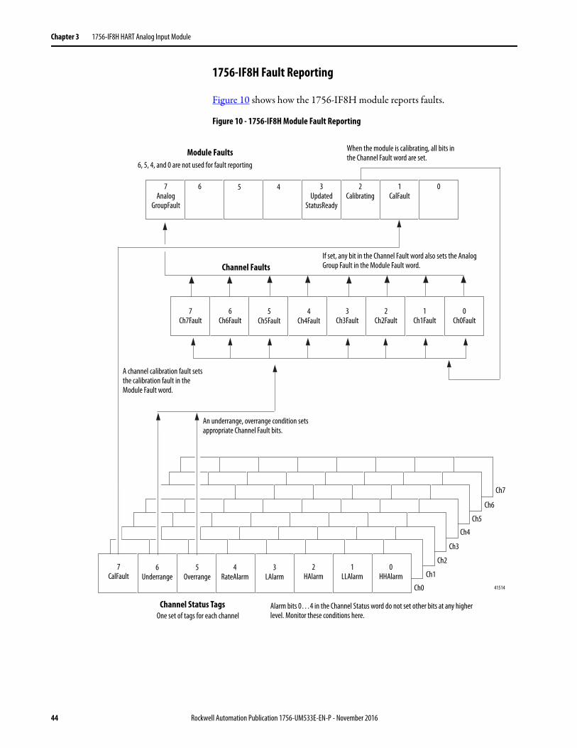
Chapter 3 1756-IF8H HART Analog Input Module
1756-IF8H Fault Reporting
Figure 10 shows how the 1756-IF8H module reports faults.
Figure 10 - 1756-IF8H Module Fault Reporting
If set, any bit in the Channel Fault word also sets the Analog Group Fault in the Module Fault word.
A channel calibration fault sets the calibration fault in the Module Fault word.
An underrange, overrange condition sets appropriate Channel Fault bits.
When the module is calibrating, all bits in the Channel Fault word are set.
Alarm bits 0…4 in the Channel Status word do not set other bits at any higher level. Monitor these conditions here.
41514
Module Faults
Channel Faults
Channel Status Tags
7Analog
GroupFault
6 2Calibrating
1CalFault
6, 5, 4, and 0 are not used for fault reporting
7Ch7Fault
6Ch6Fault
5Ch5Fault
4Ch4Fault
3Ch3Fault
2Ch2Fault
1Ch1Fault
0Ch0Fault
7CalFault
6Underrange
5Overrange
4RateAlarm
3LAlarm
2HAlarm
1LLAlarm
0HHAlarm
Ch0
Ch1
Ch2
Ch3
Ch4
Ch5
Ch6
Ch7
0
One set of tags for each channel
3Updated
StatusReady
5 4
44 Rockwell Automation Publication 1756-UM533E-EN-P - November 2016
1756-IF8H HART Analog Input Module Chapter 3
1756-IF8H Module Fault Word Bits
Bits in this word provide the highest level of fault detection. A nonzero condition in this word reveals that a fault exists on the module. You can examine further to isolate the fault. Table 7 lists tags that can be examined in ladder logic to indicate when a fault has occurred.
1756-IF8H Channel Fault Tags
During normal module operation, bits in the Channel Fault word are set if any of the respective channels has an Underrange or Overrange condition. Examine this word for a nonzero value to check quickly for Underrange or Overrange conditions on the module.
Table 8 lists conditions that set all Channel Fault word bits.
Table 7 - 1756-IF8H Tags That Can Be Examined in Ladder Logic
Tag Description
Analog Group Fault This bit is set when any bits in the Channel Fault word are set. Its tag name is AnalogGroupFault.
Calibrating This bit is set when any channel is being calibrated. When this bit is set, all bits in the Channel Fault word are set. Its tag name is Calibrating.
Calibration Fault This bit is set when any of the individual Channel Calibration Fault bits are set. Its tag name is CalFault.
Table 8 - 1756-IF8H Conditions That Set All Channel Fault Word Bits
This Condition Sets All Channel Fault Word Bits And Causes the Module to Display the Following in the Channel Fault Word Bits
A channel is being calibrated 16#00FF
A communication fault occurred between the module and its owner-controller 16#FFFF
Rockwell Automation Publication 1756-UM533E-EN-P - November 2016 45
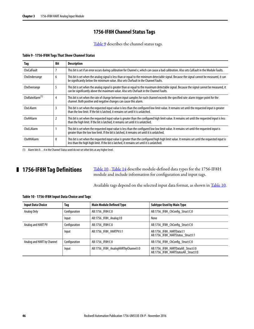
Chapter 3 1756-IF8H HART Analog Input Module
1756-IF8H Channel Status Tags
Table 9 describes the channel status tags.
1756-IF8H Tag Definitions Table 10…Table 14 describe module-defined data types for the 1756-IF8H module and include information for configuration and input tags.
Available tags depend on the selected input data format, as shown in Table 10.
Table 9 - 1756-IF8H Tags That Show Channel Status
Tag Bit Description
ChxCalFault 7 This bit is set if an error occurs during calibration for Channel x, which can cause a bad calibration. Also sets CalFault in the Module Faults.
ChxUnderrange 6 This bit is set when the analog signal is less than or equal to the minimum detectable signal. Because the signal cannot be measured, it can be significantly below the minimum value. Also sets ChxFault in the Channel Faults.
ChxOverrange 5 This bit is set when the analog signal is greater than or equal to the maximum detectable signal. Because the signal cannot be measured, it can be significantly above the maximum value. Also sets ChxFault in the Channel Faults.
ChxRateAlarm(1) 4 This bit is set when the rate of change between input samples for each channel exceeds the specified rate-alarm trigger point for the channel. Both positive and negative changes can cause this alarm.
ChxLAlarm 3 This bit is set when the requested input value is less than the configured low limit value. It remains set until the requested input is greater than the low limit. If the bit is latched, it remains set until it is unlatched.
ChxHAlarm 2 This bit is set when the requested input value is greater than the configured high limit value. It remains set until the requested input is less than the high limit. If the bit is latched, it remains set until it is unlatched.
ChxLLAlarm 1 This bit is set when the requested input value is less than the configured low low limit value. It remains set until the requested input is greater than the low low limit. If the bit is latched, it remains set until it is unlatched.
ChxHHAlarm 0 This bit is set when the requested input value is greater than the configured high high limit value. It remains set until the requested input is less than the high high limit. If the bit is latched, it remains set until it is unlatched.
(1) Alarm bits 0…4 in the Channel Status word do not set other bits at any higher level.
Table 10 - 1756-IF8H Input Data Choice and Tags
Input Data Choice Tag Main Module Defined Type Subtype Used by Main Type
Analog Only Configuration AB:1756_IF8H:C:0 AB:1756_IF8H_ChConfig_Struct:C:0
Input AB:1756_IF8H_Analog:I:0 None
Analog and HART PV Configuration AB:1756_IF8H:C:0 AB:1756_IF8H_ChConfig_Struct:C:0
Input AB:1756_IF8H_HARTPV:I:1 AB:1756_IF8H_HARTData:I:1AB:1756_IF8H_HARTStatus_Struct:I:1
Analog and HART by Channel Configuration AB:1756_IF8H:C:0 AB:1756_IF8H_ChConfig_Struct:C:0
Input AB:1756_IF8H_AnalogHARTbyChannel:I:0 AB:1756_IF8H_HARTDataAll_Struct:I:0AB:1756_IF8H_HARTStatusAll_Struct:I:0
46 Rockwell Automation Publication 1756-UM533E-EN-P - November 2016
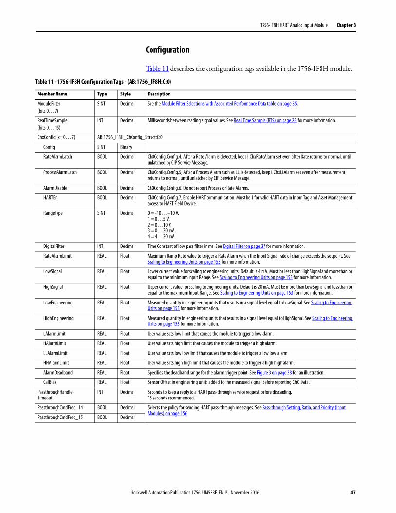
1756-IF8H HART Analog Input Module Chapter 3
Configuration
Table 11 describes the configuration tags available in the 1756-IF8H module.
Table 11 - 1756-IF8H Configuration Tags - (AB:1756_IF8H:C:0)
Member Name Type Style Description
ModuleFilter(bits 0…7)
SINT Decimal See the Module Filter Selections with Associated Performance Data table on page 35.
RealTimeSample(bits 0…15)
INT Decimal Milliseconds between reading signal values. See Real Time Sample (RTS) on page 23 for more information.
ChxConfig (x=0…7) AB:1756_IF8H_ChConfig_Struct:C:0
Config SINT Binary
RateAlarmLatch BOOL Decimal Ch0Config.Config.4, After a Rate Alarm is detected, keep I.ChxRateAlarm set even after Rate returns to normal, until unlatched by CIP Service Message.
ProcessAlarmLatch BOOL Decimal Ch0Config.Config.5, After a Process Alarm such as LL is detected, keep I.ChxLLAlarm set even after measurement returns to normal, until unlatched by CIP Service Message.
AlarmDisable BOOL Decimal Ch0Config.Config.6, Do not report Process or Rate Alarms.
HARTEn BOOL Decimal Ch0Config.Config.7, Enable HART communication. Must be 1 for valid HART data in Input Tag and Asset Management access to HART Field Device.
RangeType SINT Decimal 0 = -10…+10 V.1 = 0…5 V.2 = 0…10 V.3 = 0…20 mA.4 = 4…20 mA.
DigitalFilter INT Decimal Time Constant of low pass filter in ms. See Digital Filter on page 37 for more information.
RateAlarmLimit REAL Float Maximum Ramp Rate value to trigger a Rate Alarm when the Input Signal rate of change exceeds the setpoint. See Scaling to Engineering Units on page 153 for more information.
LowSignal REAL Float Lower current value for scaling to engineering units. Default is 4 mA. Must be less than HighSignal and more than or equal to the minimum Input Range. See Scaling to Engineering Units on page 153 for more information.
HighSignal REAL Float Upper current value for scaling to engineering units. Default is 20 mA. Must be more than LowSignal and less than or equal to the maximum Input Range. See Scaling to Engineering Units on page 153 for more information.
LowEngineering REAL Float Measured quantity in engineering units that results in a signal level equal to LowSignal. See Scaling to Engineering Units on page 153 for more information.
HighEngineering REAL Float Measured quantity in engineering units that results in a signal level equal to HighSignal. See Scaling to Engineering Units on page 153 for more information.
LAlarmLimit REAL Float User value sets low limit that causes the module to trigger a low alarm.
HAlarmLimit REAL Float User value sets high limit that causes the module to trigger a high alarm.
LLAlarmLimit REAL Float User value sets low low limit that causes the module to trigger a low low alarm.
HHAlarmLimit REAL Float User value sets high high limit that causes the module to trigger a high high alarm.
AlarmDeadband REAL Float Specifies the deadband range for the alarm trigger point. See Figure 3 on page 38 for an illustration.
CalBias REAL Float Sensor Offset in engineering units added to the measured signal before reporting Ch0.Data.
PassthroughHandleTimeout
INT Decimal Seconds to keep a reply to a HART pass-through service request before discarding. 15 seconds recommended.
PassthroughCmdFreq_14 BOOL Decimal Selects the policy for sending HART pass-through messages. See Pass-through Setting, Ratio, and Priority (Input Modules) on page 156
PassthroughCmdFreq_15 BOOL Decimal
Rockwell Automation Publication 1756-UM533E-EN-P - November 2016 47
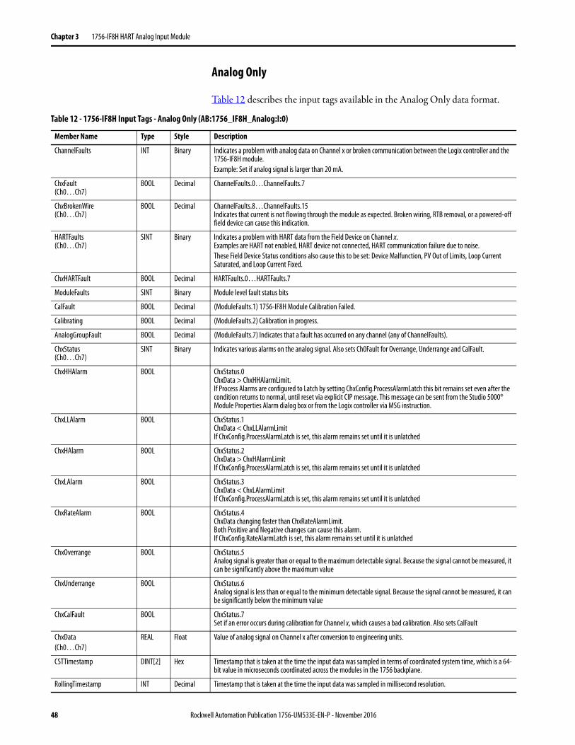
Chapter 3 1756-IF8H HART Analog Input Module
Analog Only
Table 12 describes the input tags available in the Analog Only data format.
Table 12 - 1756-IF8H Input Tags - Analog Only (AB:1756_IF8H_Analog:I:0)
Member Name Type Style Description
ChannelFaults INT Binary Indicates a problem with analog data on Channel x or broken communication between the Logix controller and the 1756-IF8H module.Example: Set if analog signal is larger than 20 mA.
ChxFault(Ch0…Ch7)
BOOL Decimal ChannelFaults.0…ChannelFaults.7
ChxBrokenWire(Ch0…Ch7)
BOOL Decimal ChannelFaults.8…ChannelFaults.15Indicates that current is not flowing through the module as expected. Broken wiring, RTB removal, or a powered-off field device can cause this indication.
HARTFaults(Ch0…Ch7)
SINT Binary Indicates a problem with HART data from the Field Device on Channel x. Examples are HART not enabled, HART device not connected, HART communication failure due to noise.These Field Device Status conditions also cause this to be set: Device Malfunction, PV Out of Limits, Loop Current Saturated, and Loop Current Fixed.
ChxHARTFault BOOL Decimal HARTFaults.0…HARTFaults.7
ModuleFaults SINT Binary Module level fault status bits
CalFault BOOL Decimal (ModuleFaults.1) 1756-IF8H Module Calibration Failed.
Calibrating BOOL Decimal (ModuleFaults.2) Calibration in progress.
AnalogGroupFault BOOL Decimal (ModuleFaults.7) Indicates that a fault has occurred on any channel (any of ChannelFaults).
ChxStatus(Ch0…Ch7)
SINT Binary Indicates various alarms on the analog signal. Also sets Ch0Fault for Overrange, Underrange and CalFault.
ChxHHAlarm BOOL ChxStatus.0 ChxData > ChxHHAlarmLimit.If Process Alarms are configured to Latch by setting ChxConfig.ProcessAlarmLatch this bit remains set even after the condition returns to normal, until reset via explicit CIP message. This message can be sent from the Studio 5000® Module Properties Alarm dialog box or from the Logix controller via MSG instruction.
ChxLLAlarm BOOL ChxStatus.1ChxData < ChxLLAlarmLimitIf ChxConfig.ProcessAlarmLatch is set, this alarm remains set until it is unlatched
ChxHAlarm BOOL ChxStatus.2ChxData > ChxHAlarmLimitIf ChxConfig.ProcessAlarmLatch is set, this alarm remains set until it is unlatched
ChxLAlarm BOOL ChxStatus.3ChxData < ChxLAlarmLimit If ChxConfig.ProcessAlarmLatch is set, this alarm remains set until it is unlatched
ChxRateAlarm BOOL ChxStatus.4ChxData changing faster than ChxRateAlarmLimit.Both Positive and Negative changes can cause this alarm.If ChxConfig.RateAlarmLatch is set, this alarm remains set until it is unlatched
ChxOverrange BOOL ChxStatus.5 Analog signal is greater than or equal to the maximum detectable signal. Because the signal cannot be measured, it can be significantly above the maximum value
ChxUnderrange BOOL ChxStatus.6 Analog signal is less than or equal to the minimum detectable signal. Because the signal cannot be measured, it can be significantly below the minimum value
ChxCalFault BOOL ChxStatus.7 Set if an error occurs during calibration for Channel x, which causes a bad calibration. Also sets CalFault
ChxData(Ch0…Ch7)
REAL Float Value of analog signal on Channel x after conversion to engineering units.
CSTTimestamp DINT[2] Hex Timestamp that is taken at the time the input data was sampled in terms of coordinated system time, which is a 64-bit value in microseconds coordinated across the modules in the 1756 backplane.
RollingTimestamp INT Decimal Timestamp that is taken at the time the input data was sampled in millisecond resolution.
48 Rockwell Automation Publication 1756-UM533E-EN-P - November 2016
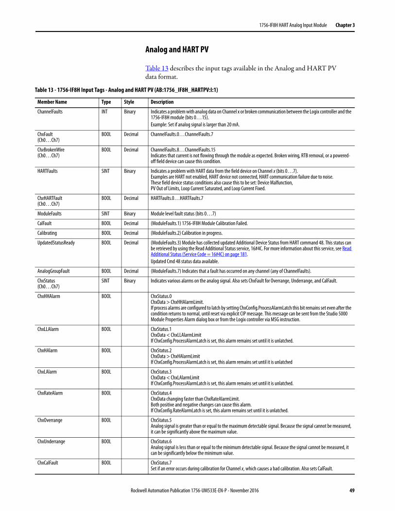
1756-IF8H HART Analog Input Module Chapter 3
Analog and HART PV
Table 13 describes the input tags available in the Analog and HART PVdata format.
Table 13 - 1756-IF8H Input Tags - Analog and HART PV (AB:1756_IF8H_HARTPV:I:1)
Member Name Type Style Description
ChannelFaults INT Binary Indicates a problem with analog data on Channel x or broken communication between the Logix controller and the 1756-IF8H module (bits 0…15).Example: Set if analog signal is larger than 20 mA.
ChxFault(Ch0…Ch7)
BOOL Decimal ChannelFaults.0…ChannelFaults.7
ChxBrokenWire(Ch0…Ch7)
BOOL Decimal ChannelFaults.8…ChannelFaults.15Indicates that current is not flowing through the module as expected. Broken wiring, RTB removal, or a powered-off field device can cause this condition.
HARTFaults SINT Binary Indicates a problem with HART data from the field device on Channel x (bits 0…7).Examples are HART not enabled, HART device not connected, HART communication failure due to noise.These field device status conditions also cause this to be set: Device Malfunction,PV Out of Limits, Loop Current Saturated, and Loop Current Fixed.
ChxHARTFault(Ch0…Ch7)
BOOL Decimal HARTFaults.0…HARTFaults.7
ModuleFaults SINT Binary Module level fault status (bits 0…7)
CalFault BOOL Decimal (ModuleFaults.1) 1756-IF8H Module Calibration Failed.
Calibrating BOOL Decimal (ModuleFaults.2) Calibration in progress.
UpdatedStatusReady BOOL Decimal (ModuleFaults.3) Module has collected updated Additional Device Status from HART command 48. This status can be retrieved by using the Read Additional Status service, 16#4C. For more information about this service, see Read Additional Status (Service Code = 16#4C) on page 181.Updated Cmd 48 status data available.
AnalogGroupFault BOOL Decimal (ModuleFaults.7) Indicates that a fault has occurred on any channel (any of ChannelFaults).
ChxStatus(Ch0…Ch7)
SINT Binary Indicates various alarms on the analog signal. Also sets ChxFault for Overrange, Underrange, and CalFault.
ChxHHAlarm BOOL ChxStatus.0 ChxData > ChxHHAlarmLimit.If process alarms are configured to latch by setting ChxConfig.ProcessAlarmLatch this bit remains set even after the condition returns to normal, until reset via explicit CIP message. This message can be sent from the Studio 5000 Module Properties Alarm dialog box or from the Logix controller via MSG instruction.
ChxLLAlarm BOOL ChxStatus.1ChxData < ChxLLAlarmLimitIf ChxConfig.ProcessAlarmLatch is set, this alarm remains set until it is unlatched.
ChxHAlarm BOOL ChxStatus.2ChxData > ChxHAlarmLimitIf ChxConfig.ProcessAlarmLatch is set, this alarm remains set until it is unlatched
ChxLAlarm BOOL ChxStatus.3ChxData < ChxLAlarmLimit If ChxConfig.ProcessAlarmLatch is set, this alarm remains set until it is unlatched.
ChxRateAlarm BOOL ChxStatus.4ChxData changing faster than ChxRateAlarmLimit.Both positive and negative changes can cause this alarm.If ChxConfig.RateAlarmLatch is set, this alarm remains set until it is unlatched.
ChxOverrange BOOL ChxStatus.5 Analog signal is greater than or equal to the maximum detectable signal. Because the signal cannot be measured, it can be significantly above the maximum value.
ChxUnderrange BOOL ChxStatus.6 Analog signal is less than or equal to the minimum detectable signal. Because the signal cannot be measured, it can be significantly below the minimum value.
ChxCalFault BOOL ChxStatus.7 Set if an error occurs during calibration for Channel x, which causes a bad calibration. Also sets CalFault.
Rockwell Automation Publication 1756-UM533E-EN-P - November 2016 49
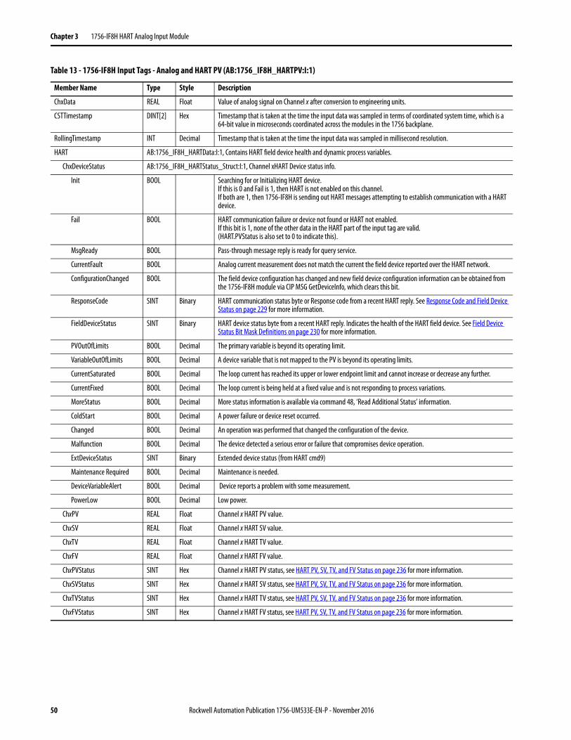
Chapter 3 1756-IF8H HART Analog Input Module
ChxData REAL Float Value of analog signal on Channel x after conversion to engineering units.
CSTTimestamp DINT[2] Hex Timestamp that is taken at the time the input data was sampled in terms of coordinated system time, which is a 64-bit value in microseconds coordinated across the modules in the 1756 backplane.
RollingTimestamp INT Decimal Timestamp that is taken at the time the input data was sampled in millisecond resolution.
HART AB:1756_IF8H_HARTData:I:1, Contains HART field device health and dynamic process variables.
ChxDeviceStatus AB:1756_IF8H_HARTStatus_Struct:I:1, Channel xHART Device status info.
Init BOOL Searching for or Initializing HART device. If this is 0 and Fail is 1, then HART is not enabled on this channel. If both are 1, then 1756-IF8H is sending out HART messages attempting to establish communication with a HART device.
Fail BOOL HART communication failure or device not found or HART not enabled. If this bit is 1, none of the other data in the HART part of the input tag are valid. (HART.PVStatus is also set to 0 to indicate this).
MsgReady BOOL Pass-through message reply is ready for query service.
CurrentFault BOOL Analog current measurement does not match the current the field device reported over the HART network.
ConfigurationChanged BOOL The field device configuration has changed and new field device configuration information can be obtained from the 1756-IF8H module via CIP MSG GetDeviceInfo, which clears this bit.
ResponseCode SINT Binary HART communication status byte or Response code from a recent HART reply. See Response Code and Field Device Status on page 229 for more information.
FieldDeviceStatus SINT Binary HART device status byte from a recent HART reply. Indicates the health of the HART field device. See Field Device Status Bit Mask Definitions on page 230 for more information.
PVOutOfLimits BOOL Decimal The primary variable is beyond its operating limit.
VariableOutOfLimits BOOL Decimal A device variable that is not mapped to the PV is beyond its operating limits.
CurrentSaturated BOOL Decimal The loop current has reached its upper or lower endpoint limit and cannot increase or decrease any further.
CurrentFixed BOOL Decimal The loop current is being held at a fixed value and is not responding to process variations.
MoreStatus BOOL Decimal More status information is available via command 48, ‘Read Additional Status’ information.
ColdStart BOOL Decimal A power failure or device reset occurred.
Changed BOOL Decimal An operation was performed that changed the configuration of the device.
Malfunction BOOL Decimal The device detected a serious error or failure that compromises device operation.
ExtDeviceStatus SINT Binary Extended device status (from HART cmd9)
Maintenance Required BOOL Decimal Maintenance is needed.
DeviceVariableAlert BOOL Decimal Device reports a problem with some measurement.
PowerLow BOOL Decimal Low power.
ChxPV REAL Float Channel x HART PV value.
ChxSV REAL Float Channel x HART SV value.
ChxTV REAL Float Channel x HART TV value.
ChxFV REAL Float Channel x HART FV value.
ChxPVStatus SINT Hex Channel x HART PV status, see HART PV, SV, TV, and FV Status on page 236 for more information.
ChxSVStatus SINT Hex Channel x HART SV status, see HART PV, SV, TV, and FV Status on page 236 for more information.
ChxTVStatus SINT Hex Channel x HART TV status, see HART PV, SV, TV, and FV Status on page 236 for more information.
ChxFVStatus SINT Hex Channel x HART FV status, see HART PV, SV, TV, and FV Status on page 236 for more information.
Table 13 - 1756-IF8H Input Tags - Analog and HART PV (AB:1756_IF8H_HARTPV:I:1)
Member Name Type Style Description
50 Rockwell Automation Publication 1756-UM533E-EN-P - November 2016
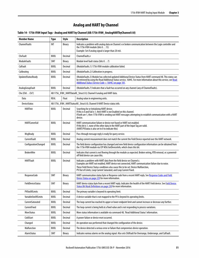
1756-IF8H HART Analog Input Module Chapter 3
Analog and HART by Channel
Table 14 - 1756-IF8H Input Tags - Analog and HART by Channel (AB:1756-IF8H_AnalogHARTbyChannel:I:0)
Member Name Type Style Description
ChannelFaults INT Binary Indicates a problem with analog data on Channel x or broken communication between the Logix controller and the 1756-IF8H module (bits 0…15)Example: Set if analog signal is larger than 20 mA.
ChxFault BOOL Decimal ChannelFaults.x
ModuleFaults SINT Binary Module level fault status (bits 0…7)
CalFault BOOL Decimal (ModuleFaults.1) 1756-IF8H module calibration failed.
Calibrating BOOL Decimal (ModuleFaults.2) Calibration in progress.
UpdatedStatusReady BOOL Decimal (ModuleFaults.3) Module has collected updated Additional Device Status from HART command 48. This status can be retrieved by using the Read Additional Status service, 16#4C. For more information about this service, see Read Additional Status (Service Code = 16#4C) on page 181.
AnalogGroupFault BOOL Decimal (ModuleFaults.7) Indicates that a fault has occurred on any channel (any of ChannelFaults).
Chx (Ch0…Ch7) AB:1756_IF8H_HARTDataAll_Struct:I:0, Channel 0 analog and HART data.
Data REAL Float Analog value in engineering units.
DeviceStatus AB:1756_IF8H_HARTStatusAll_Struct:I:0, Channel 0 HART Device status info.
HARTInit BOOL Decimal Searching for or Initializing HART device. If this is 0 and Fail is 1, then HART is not Enabled on this channel. If both are 1, then 1756-IF8H is sending out HART messages attempting to establish communication with a HART device.
HARTCommFail BOOL Decimal HART communication failure or device not found or HART not enabled. If this bit is 1, none of the other data in the HART part of the Input Tag are valid. (HART.PVStatus is also set to 0 to indicate this)
MsgReady BOOL Decimal Pass-through message reply is ready for query service.
CurrentFault BOOL Decimal Analog current measurement does not match the current the Field Device reported over the HART network.
ConfigurationChanged BOOL Decimal The field device configuration has changed and new field device configuration information can be obtained from the 1756-IF8H module via CIP MSG GetDeviceInfo, which clears this bit.
BrokenWire BOOL Decimal Indicates that current is not flowing through the module as expected. Broken wiring, RTB removal, or a powered-off field device can cause this.
HARTFault BOOL Decimal Indicates a problem with HART data from the field device on Channel x. Examples are HART not enabled, HART device not connected, HART communication failure due to noise.These Field Device Status conditions also cause this to be set: Device Malfunction,PV Out of Limits, Loop Current Saturated, and Loop Current Fixed.
ResponseCode SINT Binary HART communication status byte or Response code from a recent HART reply. See Response Codes and Field Device Status on page 229 for more information.
FieldDeviceStatus SINT Binary HART device status byte from a recent HART reply. Indicates the health of the HART Field device. See Field Device Status Bit Mask Definitions on page 230 for more information.
PVOutOfLimits BOOL Decimal The primary variable is beyond its operating limit.
VariableOutOfLimits BOOL Decimal A device variable that is not mapped to the PV is beyond its operating limits.
CurrentSaturated BOOL Decimal The loop current has reached its upper or lower endpoint limit and cannot increase or decrease any further.
CurrentFixed BOOL Decimal The loop current is being held at a fixed value and is not responding to process variations.
MoreStatus BOOL Decimal More status information is available via command 48, ‘Read Additional Status’ information.
ColdStart BOOL Decimal A power failure or device reset occurred.
Changed BOOL Decimal An operation was performed that changed the configuration of the device.
Malfunction BOOL Decimal The device detected a serious error or failure that compromises device operation.
AlarmStatus SINT Binary Indicates various alarms on the analog signal. Also sets Ch0Fault for Overrange, Underrange, and CalFault.
Rockwell Automation Publication 1756-UM533E-EN-P - November 2016 51
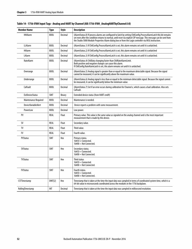
Chapter 3 1756-IF8H HART Analog Input Module
HHAlarm BOOL Decimal (AlarmStatus.0) If process alarms are configured to latch by setting Ch0Config.ProcessAlarmLatch this bit remains set even after the condition returns to normal, until reset via explicit CIP message. This message can be sent from the Studio 5000 Module Properties Alarm dialog box or from the Logix controller via MSG instruction.
LLAlarm BOOL Decimal (AlarmStatus.1) If Ch0Config.ProcessAlarmLatch is set, this alarm remains set until it is unlatched.
HAlarm BOOL Decimal (AlarmStatus.2) If Ch0Config.ProcessAlarmLatch is set, this alarm remains set until it is unlatched
LAlarm BOOL Decimal (AlarmStatus.3) If Ch0Config.ProcessAlarmLatch is set, this alarm remains set until it is unlatched.
RateAlarm BOOL Decimal (AlarmStatus.4) Ch0Data changing faster than Ch0RateAlarmLimit.Both positive and negative changes can cause this alarm.If Ch0Config.RateAlarmLatch is set, this alarm remains set until it is unlatched.
Overrange BOOL Decimal (AlarmStatus.5) Analog signal is greater than or equal to the maximum detectable signal. Because the signal cannot be measured, it can be significantly above the maximum value.
Underrange BOOL Decimal (AlarmStatus.6) Analog signal is less than or equal to the minimum detectable signal. Because the signal cannot be measured, it can be significantly below the minimum value.
CalFault BOOL Decimal (AlarmStatus.7) Set if an error occurs during calibration for Channel x, which causes a bad calibration. Also sets CalFault.
ExtDeviceStatus SINT Binary Extended device status (from HART cmd9)
Maintenance Required BOOL Decimal Maintenance is needed.
DeviceVariableAlert BOOL Decimal Device reports a problem with some measurement.
PowerLow BOOL Decimal Low power.
PV REAL Float Primary value. This value is the same value as signaled on the analog channel and is the most important measurement that is made by this device.
SV REAL Float Secondary value.
TV REAL Float Third value.
FV REAL Float Fourth value.
PVStatus SINT Hex Primary status.16#C0 = Connected.16#00 = Not Connected.
SVStatus SINT Hex Secondary status.16#C0 = Connected.16#00 = Not Connected.
TVStatus SINT Hex Third status16#C0 = Connected.16#00 = Not Connected.
FVStatus SINT Hex Fourth status.16#C0 = Connected.16#00 = Not Connected.
CSTTimestamp DINT[2] Hex Timestamp that is taken at the time the input data was sampled in terms of coordinated system time, which is a 64-bit value in microseconds coordinated across the modules in the 1756 backplane.
RollingTimestamp INT Decimal Timestamp that is taken at the time the input data was sampled in millisecond resolution.
Table 14 - 1756-IF8H Input Tags - Analog and HART by Channel (AB:1756-IF8H_AnalogHARTbyChannel:I:0)
Member Name Type Style Description
52 Rockwell Automation Publication 1756-UM533E-EN-P - November 2016
Chapter 4
1756-IF8IH HART Isolated Analog Input Module
Module Features The 1756-IF8IH module is an isolated, 8-channel, current-only input module capable of HART communication on all channels. Each channel is individually configurable.
The 1756-IF8IH module has the following features:• Eight isolated, individually configurable input channels with a separate
HART modem on each channel• Channel-to-channel, channel-to-backplane, and channel-to-frame
ground galvanic isolation at a continuous level of 250V AC rms• Two input ranges: 0...20 mA and 4...20 mA • Choice of four data formats:
• Analog Only• Analog and HART PV• Analog and HART by channel with Configure HART Device = No• Analog and HART by channel with Configure HART Device = Yes
• Supports full simultaneous HART 1200 baud bandwidth to all channels• Channel ADC filter (one setting per module)• Digital filtering (configurable per channel)• Real-time sampling• Auto-scanning of HART variables (PV, SV, TV, FV)• HART pass-through interface• Option to configure a HART device with user-supplied data. You can
configure PV damping value, PV range values, PV transfer function, and PV units code. This option is available only when the data format is Analog and HART by Channel with Configure HART device = Yes
• User scaling of input data
Topic Page
Module Features 53
Wire the Module 61
Circuit Diagram 61
1756-IF8IH Module Fault and Status Reporting 62
Module Calibration 64
Module-defined Data Types, 1756-IF8IH Module 65
Rockwell Automation Publication 1756-UM533E-EN-P - November 2016 53
Chapter 4 1756-IF8IH HART Isolated Analog Input Module
• Time stamping• Alarms and fault detection
– Open wire detection(4...20 mA range)– Underrange and overrange detection– Fault reporting– Process and Rate alarms and alarm latching
(only if Configure HART Device = No)– Status indicator information
• User Calibration via CIP messaging • Calibration via output word (available only when the data format is
Analog and HART by Channel with Configure HART Device = Yes)• Downloadable firmware using ControlFlash™• Add-on Profile• “Bumpless” configuration for a smooth transition in new configurations.• Removal and insertion under power (RIUP)
HART Compatibility
The 1756-IF8IH functions as a HART master. It communicates with HART devices that have a HART revision of 5, 6, or 7. Each channel has its own HART modem and functions as a HART primary master.
The 1756-IF8IH module supports one HART device per channel.
The 1756-IF8IH module does not support burst mode, phase shift keying (PSK), or multi-drop network configuration. The module detects and turns off a bursting device at initial connection with the device.
HART Handheld Configurator
A HART handheld configuration tool can be connected to the HART device while the module is connected as long as the configuration tool is the secondary master.
54 Rockwell Automation Publication 1756-UM533E-EN-P - November 2016
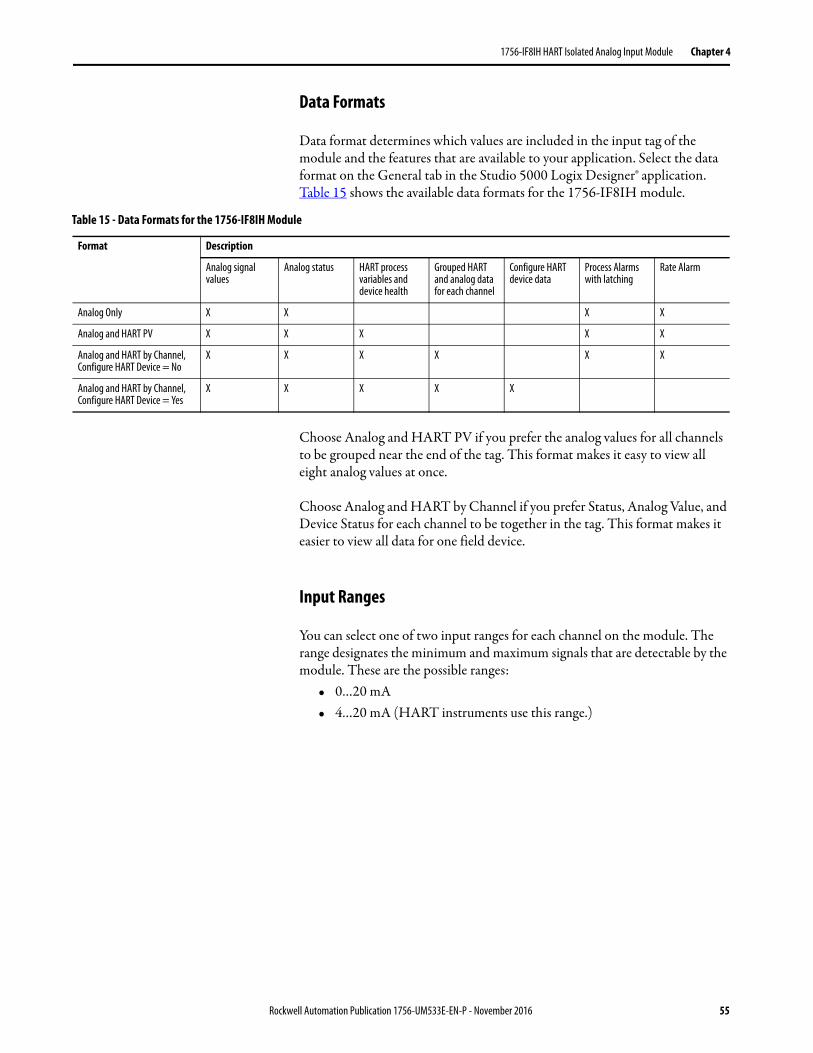
1756-IF8IH HART Isolated Analog Input Module Chapter 4
Data Formats
Data format determines which values are included in the input tag of the module and the features that are available to your application. Select the data format on the General tab in the Studio 5000 Logix Designer® application. Table 15 shows the available data formats for the 1756-IF8IH module.
Choose Analog and HART PV if you prefer the analog values for all channels to be grouped near the end of the tag. This format makes it easy to view all eight analog values at once.
Choose Analog and HART by Channel if you prefer Status, Analog Value, and Device Status for each channel to be together in the tag. This format makes it easier to view all data for one field device.
Input Ranges
You can select one of two input ranges for each channel on the module. The range designates the minimum and maximum signals that are detectable by the module. These are the possible ranges:
• 0…20 mA• 4…20 mA (HART instruments use this range.)
Table 15 - Data Formats for the 1756-IF8IH Module
Format Description
Analog signal values
Analog status HART process variables and device health
Grouped HART and analog data for each channel
Configure HART device data
Process Alarms with latching
Rate Alarm
Analog Only X X X X
Analog and HART PV X X X X X
Analog and HART by Channel, Configure HART Device = No
X X X X X X
Analog and HART by Channel, Configure HART Device = Yes
X X X X X
Rockwell Automation Publication 1756-UM533E-EN-P - November 2016 55
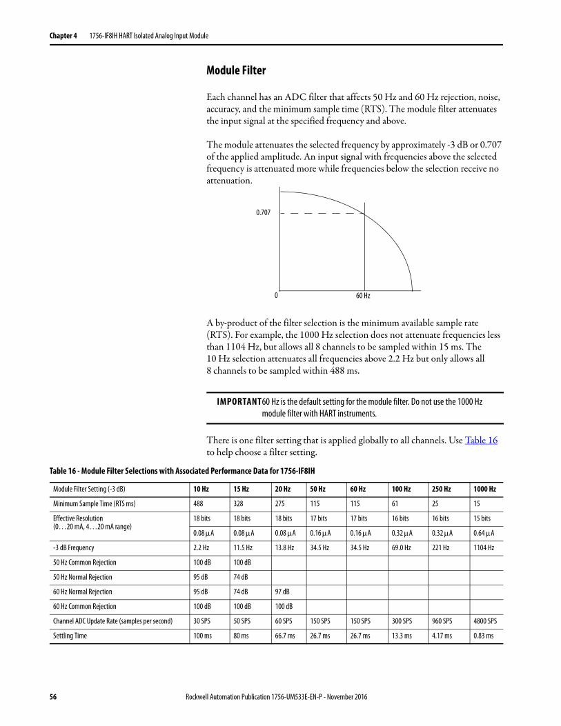
Chapter 4 1756-IF8IH HART Isolated Analog Input Module
Module Filter
Each channel has an ADC filter that affects 50 Hz and 60 Hz rejection, noise, accuracy, and the minimum sample time (RTS). The module filter attenuates the input signal at the specified frequency and above.
The module attenuates the selected frequency by approximately -3 dB or 0.707 of the applied amplitude. An input signal with frequencies above the selected frequency is attenuated more while frequencies below the selection receive no attenuation.
A by-product of the filter selection is the minimum available sample rate (RTS). For example, the 1000 Hz selection does not attenuate frequencies less than 1104 Hz, but allows all 8 channels to be sampled within 15 ms. The 10 Hz selection attenuates all frequencies above 2.2 Hz but only allows all 8 channels to be sampled within 488 ms.
There is one filter setting that is applied globally to all channels. Use Table 16 to help choose a filter setting.
IMPORTANT60 Hz is the default setting for the module filter. Do not use the 1000 Hz module filter with HART instruments.
0.707
60 Hz0
Table 16 - Module Filter Selections with Associated Performance Data for 1756-IF8IH
Module Filter Setting (-3 dB) 10 Hz 15 Hz 20 Hz 50 Hz 60 Hz 100 Hz 250 Hz 1000 Hz
Minimum Sample Time (RTS ms) 488 328 275 115 115 61 25 15
Effective Resolution (0…20 mA, 4…20 mA range)
18 bits 18 bits 18 bits 17 bits 17 bits 16 bits 16 bits 15 bits
0.08 A 0.08 A 0.08 A 0.16 A 0.16 A 0.32 A 0.32 A 0.64 A
-3 dB Frequency 2.2 Hz 11.5 Hz 13.8 Hz 34.5 Hz 34.5 Hz 69.0 Hz 221 Hz 1104 Hz
50 Hz Common Rejection 100 dB 100 dB
50 Hz Normal Rejection 95 dB 74 dB
60 Hz Normal Rejection 95 dB 74 dB 97 dB
60 Hz Common Rejection 100 dB 100 dB 100 dB
Channel ADC Update Rate (samples per second) 30 SPS 50 SPS 60 SPS 150 SPS 150 SPS 300 SPS 960 SPS 4800 SPS
Settling Time 100 ms 80 ms 66.7 ms 26.7 ms 26.7 ms 13.3 ms 4.17 ms 0.83 ms
56 Rockwell Automation Publication 1756-UM533E-EN-P - November 2016
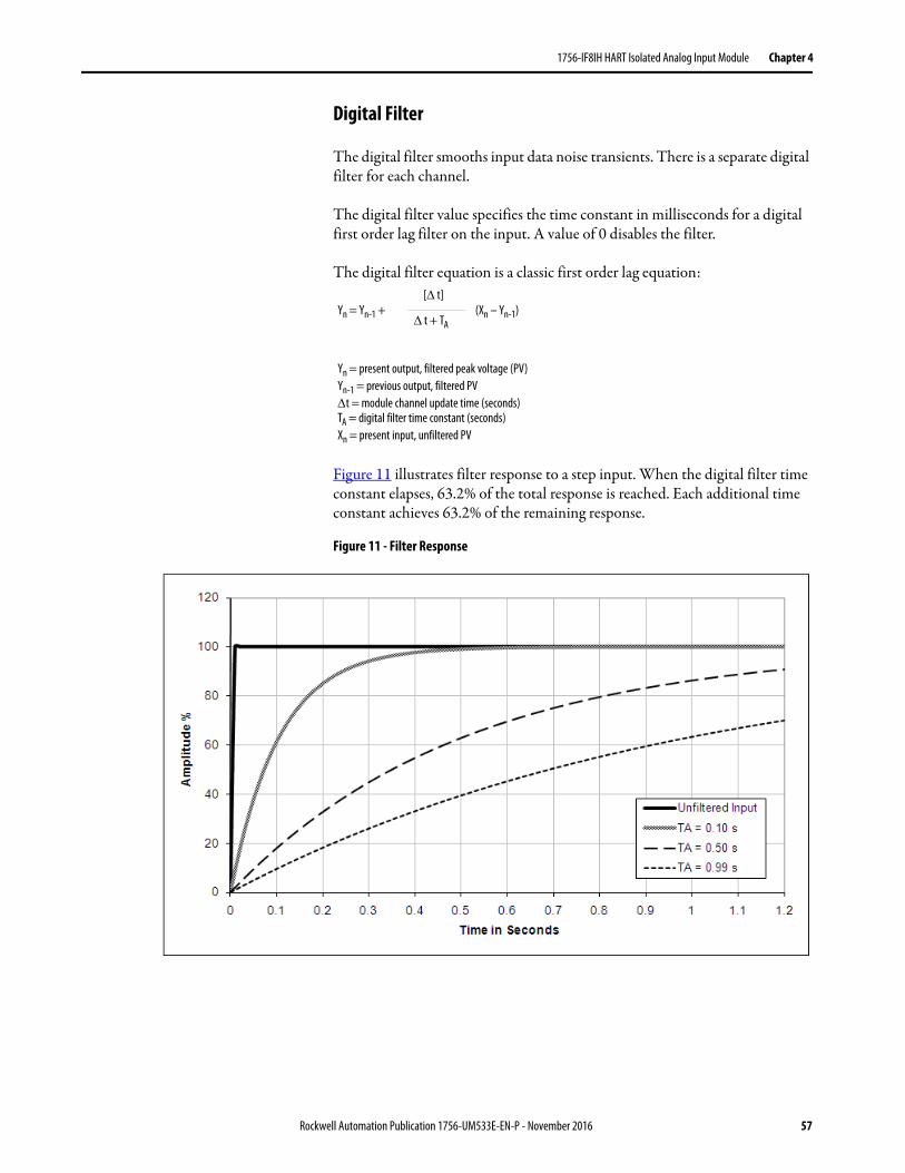
1756-IF8IH HART Isolated Analog Input Module Chapter 4
Digital Filter
The digital filter smooths input data noise transients. There is a separate digital filter for each channel.
The digital filter value specifies the time constant in milliseconds for a digital first order lag filter on the input. A value of 0 disables the filter.
The digital filter equation is a classic first order lag equation:
Figure 11 illustrates filter response to a step input. When the digital filter time constant elapses, 63.2% of the total response is reached. Each additional time constant achieves 63.2% of the remaining response.
Figure 11 - Filter Response
Yn = Yn-1 + (Xn – Yn-1)[ t]
t + TA
Yn = present output, filtered peak voltage (PV)Yn-1 = previous output, filtered PVt = module channel update time (seconds)TA = digital filter time constant (seconds)Xn = present input, unfiltered PV
Rockwell Automation Publication 1756-UM533E-EN-P - November 2016 57
Chapter 4 1756-IF8IH HART Isolated Analog Input Module
Real-time Sampling
This parameter instructs the module how often to scan its input channels and obtain new sampled data. After the channels are scanned, the module broadcasts that data (multicast or unicast) to the local chassis backplane. This feature is applied on a module-wide basis.
During module configuration, you specify a real-time sampling (RTS) period and a requested packet interval (RPI). Both of these features instruct the module to broadcast data, but only the RTS feature instructs the module to scan its channels before broadcasting.
For more RTS information, see Real Time Sample (RTS) on page 23.
Underrange and Overrange DetectionThe module detects when it is operating beyond limits of the input range. This status indication tells you that the input signal is not being measured accurately because the signal is beyond the measuring capability of the module. For example, the module cannot distinguish 20.58…30 mA.
Table 17 shows the input ranges of the 1756-IF8IH module and the lowest and highest signal available in each range before the module detects an underrange and overrange condition.
Open Circuit Detection
In the 4...20 mA range, if the signal wire to a channel opens, the module reports a negative full-scale value in the input data tag of the channel within 5 seconds. The module also sets the ChxBrokenWire status bit.
In the 0...20 mA range, an open-circuit condition results in a measured value of 0 mA, which is the same as a measured value of 0 mA when there is not an open-circuit condition. The appropriate Underrange bit is set but the ChxBrokenWire bit is not set.
Table 17 - Low and High Signal Limits on the 1756-IF8IH Module
Input Module Available Range Lowest Signal in Range Highest Signal in Range
1756-IF8IH 0…20 mA 0 mA 20.58 mA
4…20 mA 3.42 mA 20.58 mA
58 Rockwell Automation Publication 1756-UM533E-EN-P - November 2016
1756-IF8IH HART Isolated Analog Input Module Chapter 4
Auto-Configure HART Device
The Auto-Configure HART device feature automatically configures a HART device with certain user-supplied values. Configurable values are PV Damping, PV Range, PV Range Units Code, and PV Transfer Function. You specify the configuration values in the Logix Designer application. One checkbox enables the PV damping value configuration and another enables configuration of PV range, PV transfer function, and PV units. The specified values are sent to the device at device connection time or if the module detects that the device configuration bit is set. See HART Command Tab - 1756-IF8IH, 1756-OF8IH on page 169.
The specified values are sent to the device only if the feature is enabled and the module detects that the values in the device are not within 1% of the values in the configuration tag. If the PV Range enable bit is set and the module detects that the device PV Units Code does not match the value in the configuration tag, the module sends the PV Units Code to the module. The PV Damping, PV units code, PV Upper and Lower Range values, and PV Transfer Function reside in the configuration table. If the write operation fails (for example, device write protected or unsupported values) then a status flag is set to indicate that the device is not configured properly. If the write is successful, the module verifies that the PV Range and Damping values that are read from the device are within 1.0% of the values in the configuration tag. If they are not, an error is flagged.
The valid range of HART configuration values depends on the HART device that is connected to the module. The Logix Designer application does not check that the values that are entered in the HART Command tab are appropriate. Confirm on your own that valid values for your HART devices are used.
Rate Alarm
This feature is not available if Configure HART Device = Yes.
The value for the Rate Alarm Limit is entered in scaled engineering units per second. The rate alarm triggers if the rate of change between input samples for a channel exceeds the specified rate-alarm trigger point for that channel. Rate Alarm uses the signal value after filtering by the Module Filter and before the Digital Filter is applied.
Rockwell Automation Publication 1756-UM533E-EN-P - November 2016 59

Chapter 4 1756-IF8IH HART Isolated Analog Input Module
Process Alarms
This feature is not available if Configure HART Device = Yes.
This feature enables you to specify alarm limits for input level and have the module report when those levels have been exceeded. It is available only if Configure HART Device = No. In module configuration, you specify values for high-high, high, low, and low-low limits. Process alarms can be latched.
Only status bits in the input table are affected during runtime after a valid configuration; no fault bit is set.
AlarmDeadband determines when the AlarmLimit bits are cleared. Once the bit is set by exceeding the AlarmLimit, it cannot be cleared until the input has passed the deadband delta from the AlarmLimit value. For example, if the deadband is 0.5 and the HAlarmLimit is 10.0, the HAlarm status bit is not cleared until the input is 9.5 or less. Likewise, if the LAlarmLimit is 1.0, the associated LAlarm bit would clear when the input is 1.5 or more for the same deadband value.
Alarm bits are cleared when the input falls inside the specified Alarm Limit. The exception is when ProcessAlarmLatch is set in the configuration. In that case, clearing alarm bits requires the command ‘Unlatch Alarm Status’ be issued to all alarms or individual alarms.
For more information, see Process Alarms on page 38.
60 Rockwell Automation Publication 1756-UM533E-EN-P - November 2016
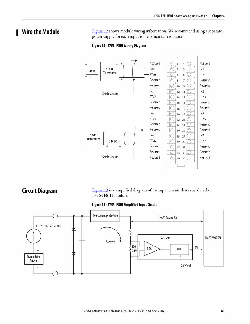
1756-IF8IH HART Isolated Analog Input Module Chapter 4
Wire the Module Figure 12 shows module wiring information. We recommend using a separate power supply for each input to help maintain isolation.
Figure 12 - 1756-IF8IH Wiring Diagram
Circuit Diagram Figure 13 is a simplified diagram of the input circuit that is used in the 1756-IF8IH module.
Figure 13 - 1756-IF8IH Simplified Input Circuit
+
–
i
i1
3
5
7
01 9
1112
41 31
61 51
81 71
02 91
22 12
42 32
62 52
82 72
03 92
23 13
33
63 53
2
34
8
6
4
+
–
Not Used
IN0
RTN0Reserved
Reserved
IN2
RTN2Reserved
Reserved
IN4
RTN4Reserved
Reserved
IN6
RTN6Reserved
Reserved
Not Used
Shield Ground
24V DC
24V DC
2-wire Transmitter
Shield Ground
+
–
+ –
Not Used
IN1
RTN1Reserved
Reserved
IN3
RTN3Reserved
Reserved
IN5
RTN5Reserved
Reserved
IN7
RTN7Reserved
Reserved
Not Used
4-wire Transmitter
Overcurrent protectionHART Tx and Rx
Transmitter Power
4 ~ 20 mA Transmitter
I_Sense
PGA
AD1792
+
-
ADC
HART MODEM
SPI
2.5v Vref
1000.1%
Rockwell Automation Publication 1756-UM533E-EN-P - November 2016 61
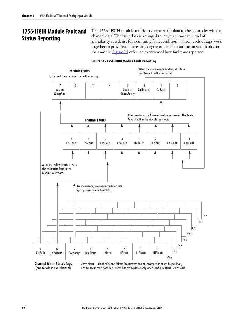
Chapter 4 1756-IF8IH HART Isolated Analog Input Module
1756-IF8IH Module Fault and Status Reporting
The 1756-IF8IH module multicasts status/fault data to the controller with its channel data. The fault data is arranged to let you choose the level of granularity you desire for examining fault conditions. Three levels of tags work together to provide an increasing degree of detail about the cause of faults on the module. Figure 14 offers an overview of how faults are reported.
Figure 14 - 1756-IF8IH Module Fault Reporting
If set, any bit in the Channel Fault word also sets the Analog Group Fault in the Module Fault word.
A channel calibration fault sets the calibration fault in the Module Fault word.
An underrange, overrange condition sets appropriate Channel Fault bits.
Alarm bits 0…4 in the Channel/Alarm Status word do not set other bits at any higher level; monitor these conditions here. These bits are available only when Configure HART Device = No.
Module Faults
Channel Faults
Channel Alarm Status Tags(one set of tags per channel)
7Analog
GroupFault
6 2Calibrating
1CalFault
6, 5, 4, and 0 are not used for fault reporting
7Ch7Fault
6Ch6Fault
5Ch5Fault
4Ch4Fault
3Ch3Fault
2Ch2Fault
1Ch1Fault
0Ch0Fault
7CalFault
6Underrange
5Overrange
4RateAlarm
3LAlarm
2HAlarm
1LLAlarm
0HHAlarm
Ch0
Ch1
Ch2
Ch3
Ch4
Ch5
Ch6
Ch7
03Updated
StatusReady
5 4
When the module is calibrating, all bits in the Channel Fault word are set.
62 Rockwell Automation Publication 1756-UM533E-EN-P - November 2016
1756-IF8IH HART Isolated Analog Input Module Chapter 4
Table 18 lists tags you can examine in ladder logic to indicate when a fault has occurred.
1756-IF8IH Module Fault Word Bits
Bits in this word provide the highest level of fault detection. A nonzero condition in this word reveals that a fault exists on the module. You can examine further to isolate the fault. Table 19 lists tags that can be examined in ladder logic to indicate when a fault has occurred.
1756-IF8IH Channel Fault Tags
During normal module operation, bits in the Channel Fault word are set if any of the respective channels has an Underrange or Overrange condition. Examine this word for a nonzero value to check for Underrange or Overrange conditions on the module.
Table 20 lists conditions that set all Channel Fault word bits.
Table 18 - 1756-IF8IH Tags That Can Be Examined in Ladder Logic
Tag Description Tag NameAnalog and HART PV
Tag NameAnalog and HART by Channel(1)
Module Fault Word This word provides fault summary reporting. ModuleFaults ModuleFaults
Channel Fault Word This word provides underrange, overrange, and communication fault reporting.
ChannelFaultsChxFault
ChannelFaultsChxFault
Channel Status Word These words provide individual channel underrange and overrange fault indications and reporting for process alarms, rate alarms, and calibration faults.
ChxStatus Chx.DeviceStatus.AlarmStatus
HART Faults These bits provide HART communication status. HARTFaults Chx.DeviceStatus.HARTFault
HART Device Status This data reports HART field device health. HART.ChxDevice Status Chx.DeviceStatus.FieldDeviceStatus
(1) Available only for 1756-IF8H firmware revision 2.001.
Table 19 - 1756-IF8IH Tags That Can Be Examined in Ladder Logic
Tag Description
Analog Group Fault This bit is set when any bits in the Channel Fault word are set. Its tag name is AnalogGroupFault.
Calibrating This bit is set when any channel is being calibrated. When this bit is set, all bits in the Channel Fault word are set. Its tag name is Calibrating.
Calibration Fault This bit is set when any of the individual Channel Calibration Fault bits are set. Its tag name is CalFault.
Table 20 - 1756-IF8IH Conditions That Set All Channel Fault Word Bits
This Condition Sets All Channel Fault Word Bits And Causes the Module to Display the Following in the Channel Fault Word Bits
A channel is being calibrated 16#00FF
A communication fault occurred between the module and its owner-controller 16#FFFF
Rockwell Automation Publication 1756-UM533E-EN-P - November 2016 63
Chapter 4 1756-IF8IH HART Isolated Analog Input Module
Module Calibration There are two ways to initiate calibration of the 1756-IF8IH module:• Logix Designer application Calibration tab• Module Output Word
Module Calibration Via Logix Designer Application
The Calibration tab in the Logix Designer application provides a button to initiate module calibration and a display of the results. Refer to Calibration Tab on page 170 for more information.
Module Calibration Via Output Word
The 1756-IF8IH module allows you to perform calibration by setting and clearing bits in the module output word. This method of calibration is available only when Configure HART Device = Yes. The module must be connected to a controller and the controller must be in run mode.
See Table 28 on page 74 for descriptions of the tags in the1756-IF8IH output word.
To perform a module calibration via the output word, set and clear bits in sequence to perform the calibration tasks. This table shows 1756-IF8IH calibration bits.
Step Output Word Bit
Description
Set the calibration date CalibrationDate The date that you want to be associated with this calibration; typically the current date. Set the date before starting the calibration.
Initiate calibration ChxCalibrate Set this bit to initiate calibration, and keep it set until the calibration sequence is complete. If this bit clears before the calibration is complete, the calibration is aborted.
Perform low calibration ChxCalLowRef Perform low calibration at the low reference point (0.5 mA). Connect a valid low reference signal before setting this bit.
Perform high calibration ChxCalHighRef Perform high calibration at the high reference point (20 mA). Connect a valid high reference signal before setting this bit.
Abort calibration ChxCalibrateChxCalLowRefChxCalHighRef
Setting all three calibration bits aborts a calibration.
64 Rockwell Automation Publication 1756-UM533E-EN-P - November 2016
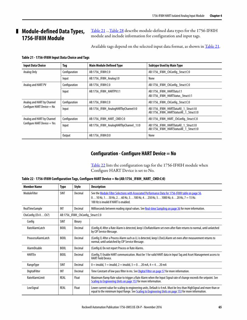
1756-IF8IH HART Isolated Analog Input Module Chapter 4
Module-defined Data Types, 1756-IF8IH Module
Table 21 …Table 28 describe module-defined data types for the 1756-IF8IH module and include information for configuration and input tags.
Available tags depend on the selected input data format, as shown in Table 21.
Configuration - Configure HART Device = No
Table 22 lists the configuration tags for the 1756-IF8IH module when Configure HART Device is set to No.
Table 21 - 1756-IF8IH Input Data Choice and Tags
Input Data Choice Tag Main Module Defined Type Subtype Used by Main Type
Analog Only Configuration AB:1756_IF8IH:C:0 AB:1756_IF8IH_ChConfig_Struct:C:0
Input AB:1756_IF8IH_Analog:I:0 None
Analog and HART PV Configuration AB:1756_IF8IH:C:0 AB:1756_IF8IH_ChConfig_Struct:C:0
Input AB:1756_IF8IH_HARTPV:I:1 AB:1756_IF8IH_HARTData:I:1AB:1756_IF8IH_HARTStatus_Struct:I:1
Analog and HART by ChannelConfigure HART Device = No
Configuration AB:1756_IF8IH:C:0 AB:1756_IF8IH_ChConfig_Struct:C:0
Input AB:1756_IF8IH_AnalogHARTbyChannel:I:0 AB:1756_IF8IH_HARTDataAll_1_Struct:I:0AB:1756_IF8IH_HARTStatusAll_1_Struct:I:0
Analog and HART by ChannelConfigure HART Device = Yes
Configuration AB:1756_IF8IH_HART_CMD:C:0 AB:1756_IF8IH_HART_ChConfig_Struct:C:0
Input AB:1756_IF8IH_AnalogHARTbyChannel_1:I:0 AB:1756_IF8IH_HARTDataAll_1_Struct:I:0AB:1756_IF8IH_HARTStatusAll_1_Struct:I:0
Output AB:1756_IF8IH:O:0 None
Table 22 - 1756-IF8IH Configuration Tags, Configure HART Device = No (AB:1756_IF8IH_HART_CMD:C:0)
Member Name Type Style Description
ModuleFilter SINT Decimal See the Module Filter Selections with Associated Performance Data for 1756-IF8IH table on page 56.0…10 Hz, 1…50 Hz, 2…60 Hz, 3…100 Hz, 4…250 Hz, 5…1000 Hz, 6…20 Hz, 7 = 15 Hz.100 Hz is invalid if HART is enabled.
RealTimeSample INT Decimal Milliseconds between reading signal values. See Real-time Sampling on page 36 for more information.
ChxConfig (Ch 0…Ch7) AB:1756_IF8IH_ChConfig_Struct:C:0
Config SINT Binary
RateAlarmLatch BOOL Decimal (Config.4) After a Rate Alarm is detected, keep I.ChxRateAlarm set even after Rate returns to normal, until unlatched by CIP Service Message.
ProocessAlarmLatch BOOL Decimal (Config.5) After a Process Alarm such as LL is detected, keep I.ChxLLAlarm set even after measurement returns to normal, until unlatched by CIP Service Message.
AlarmDisable BOOL Decimal (Config.6) Do not report Process or Rate Alarms.
HARTEn BOOL Decimal (Config.7) Enable HART communication. Must be 1 for valid HART data in Input Tag and Asset Management access to HART Field Device.
RangeType SINT Decimal 0 = invalid, 1 = invalid, 2 = invalid, 3 = 0…20 mA, 4 = 4…20 mA
DigitalFilter INT Decimal Time Constant of low pass filter in ms. See Digital Filter on page 57 for more information.
RateAlarmLimit REAL Float Maximum Ramp Rate value to trigger a Rate Alarm when the Input Signal rate of change exceeds the setpoint. See Scaling to Engineering Units on page 153 for more information.
LowSignal REAL Float Lower current value for scaling to engineering units. Default is 4 mA. Must be less than HighSignal and more than or equal to the minimum Input Range. See Scaling to Engineering Units on page 153 for more information.
Rockwell Automation Publication 1756-UM533E-EN-P - November 2016 65
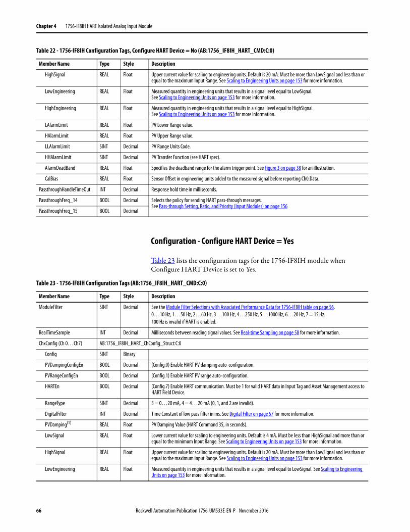
Chapter 4 1756-IF8IH HART Isolated Analog Input Module
Configuration - Configure HART Device = Yes
Table 23 lists the configuration tags for the 1756-IF8IH module when Configure HART Device is set to Yes.
HighSignal REAL Float Upper current value for scaling to engineering units. Default is 20 mA. Must be more than LowSignal and less than or equal to the maximum Input Range. See Scaling to Engineering Units on page 153 for more information.
LowEngineering REAL Float Measured quantity in engineering units that results in a signal level equal to LowSignal. See Scaling to Engineering Units on page 153 for more information.
HighEngineering REAL Float Measured quantity in engineering units that results in a signal level equal to HighSignal. See Scaling to Engineering Units on page 153 for more information.
LAlarmLimit REAL Float PV Lower Range value.
HAlarmLimit REAL Float PV Upper Range value.
LLAlarmLimit SINT Decimal PV Range Units Code.
HHAlarmLimit SINT Decimal PV Transfer Function (see HART spec).
AlarmDeadBand REAL Float Specifies the deadband range for the alarm trigger point. See Figure 3 on page 38 for an illustration.
CalBias REAL Float Sensor Offset in engineering units added to the measured signal before reporting Ch0.Data.
PassthroughHandleTimeOut INT Decimal Response hold time in milliseconds.
PassthroughFreq_14 BOOL Decimal Selects the policy for sending HART pass-through messages. See Pass-through Setting, Ratio, and Priority (Input Modules) on page 156
PassthroughFreq_15 BOOL Decimal
Table 22 - 1756-IF8IH Configuration Tags, Configure HART Device = No (AB:1756_IF8IH_HART_CMD:C:0)
Member Name Type Style Description
Table 23 - 1756-IF8IH Configuration Tags (AB:1756_IF8IH_HART_CMD:C:0)
Member Name Type Style Description
ModuleFilter SINT Decimal See the Module Filter Selections with Associated Performance Data for 1756-IF8IH table on page 56.0…10 Hz, 1…50 Hz, 2…60 Hz, 3…100 Hz, 4…250 Hz, 5…1000 Hz, 6…20 Hz, 7 = 15 Hz.100 Hz is invalid if HART is enabled.
RealTimeSample INT Decimal Milliseconds between reading signal values. See Real-time Sampling on page 58 for more information.
ChxConfig (Ch 0…Ch7) AB:1756_IF8IH_HART_ChConfig_Struct:C:0
Config SINT Binary
PVDampingConfigEn BOOL Decimal (Config.0) Enable HART PV damping auto-configuration.
PVRangeConfigEn BOOL Decimal (Config.1) Enable HART PV range auto-configuration.
HARTEn BOOL Decimal (Config.7) Enable HART communication. Must be 1 for valid HART data in Input Tag and Asset Management access to HART Field Device.
RangeType SINT Decimal 3 = 0…20 mA, 4 = 4…20 mA (0, 1, and 2 are invalid).
DigitalFilter INT Decimal Time Constant of low pass filter in ms. See Digital Filter on page 57 for more information.
PVDamping(1) REAL Float PV Damping Value (HART Command 35, in seconds).
LowSignal REAL Float Lower current value for scaling to engineering units. Default is 4 mA. Must be less than HighSignal and more than or equal to the minimum Input Range. See Scaling to Engineering Units on page 153 for more information.
HighSignal REAL Float Upper current value for scaling to engineering units. Default is 20 mA. Must be more than LowSignal and less than or equal to the maximum Input Range. See Scaling to Engineering Units on page 153 for more information.
LowEngineering REAL Float Measured quantity in engineering units that results in a signal level equal to LowSignal. See Scaling to Engineering Units on page 153 for more information.
66 Rockwell Automation Publication 1756-UM533E-EN-P - November 2016
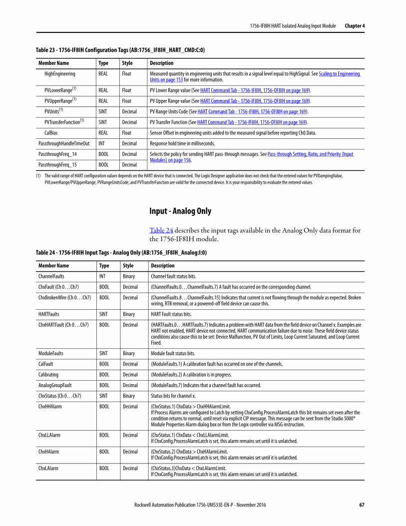
1756-IF8IH HART Isolated Analog Input Module Chapter 4
Input - Analog Only
Table 24 describes the input tags available in the Analog Only data format for the 1756-IF8IH module.
HighEngineering REAL Float Measured quantity in engineering units that results in a signal level equal to HighSignal. See Scaling to Engineering Units on page 153 for more information.
PVLowerRange(1) REAL Float PV Lower Range value (See HART Command Tab - 1756-IF8IH, 1756-OF8IH on page 169).
PVUpperRange(1) REAL Float PV Upper Range value (See HART Command Tab - 1756-IF8IH, 1756-OF8IH on page 169).
PVUnits(1) SINT Decimal PV Range Units Code (See HART Command Tab - 1756-IF8IH, 1756-OF8IH on page 169).
PVTransferFunction(1) SINT Decimal PV Transfer Function (See HART Command Tab - 1756-IF8IH, 1756-OF8IH on page 169).
CalBias REAL Float Sensor Offset in engineering units added to the measured signal before reporting Ch0.Data.
PassthroughHandleTimeOut INT Decimal Response hold time in milliseconds.
PassthroughFreq_14 BOOL Decimal Selects the policy for sending HART pass-through messages. See Pass-through Setting, Ratio, and Priority (Input Modules) on page 156.
PassthroughFreq_15 BOOL Decimal
(1) The valid range of HART configuration values depends on the HART device that is connected. The Logix Designer application does not check that the entered values for PVDampingValue, PVLowerRange/PVUpperRange, PVRangeUnitsCode, and PVTransferFunction are valid for the connected device. It is your responsibility to evaluate the entered values.
Table 23 - 1756-IF8IH Configuration Tags (AB:1756_IF8IH_HART_CMD:C:0)
Member Name Type Style Description
Table 24 - 1756-IF8IH Input Tags - Analog Only (AB:1756_IF8IH_Analog:I:0)
Member Name Type Style Description
ChannelFaults INT Binary Channel fault status bits.
ChxFault (Ch 0…Ch7) BOOL Decimal (ChannelFaults.0…ChannelFaults.7) A fault has occurred on the corresponding channel.
ChxBrokenWire (Ch 0…Ch7) BOOL Decimal (ChannelFaults.8…ChannelFaults.15) Indicates that current is not flowing through the module as expected. Broken wiring, RTB removal, or a powered-off field device can cause this.
HARTFaults SINT Binary HART Fault status bits.
ChxHARTFault (Ch 0…Ch7) BOOL Decimal (HARTFaults.0…HARTFaults.7) Indicates a problem with HART data from the field device on Channel x. Examples are HART not enabled, HART device not connected, HART communication failure due to noise. These field device status conditions also cause this to be set: Device Malfunction, PV Out of Limits, Loop Current Saturated, and Loop Current Fixed.
ModuleFaults SINT Binary Module fault status bits.
CalFault BOOL Decimal (ModuleFaults.1) A calibration fault has occurred on one of the channels.
Calibrating BOOL Decimal (ModuleFaults.2) A calibration is in progress.
AnalogGroupFault BOOL Decimal (ModuleFaults.7) Indicates that a channel fault has occurred.
ChxStatus (Ch 0…Ch7) SINT Binary Status bits for channel x.
ChxHHAlarm BOOL Decimal (ChxStatus.1) ChxData > ChxHHAlarmLimit.If Process Alarms are configured to Latch by setting ChxConfig.ProcessAlarmLatch this bit remains set even after the condition returns to normal, until reset via explicit CIP message. This message can be sent from the Studio 5000® Module Properties Alarm dialog box or from the Logix controller via MSG instruction.
ChxLLAlarm BOOL Decimal (ChxStatus.1) ChxData < ChxLLAlarmLimit.If ChxConfig.ProcessAlarmLatch is set, this alarm remains set until it is unlatched.
ChxHAlarm BOOL Decimal (ChxStatus.2) ChxData > ChxHAlarmLimit.If ChxConfig.ProcessAlarmLatch is set, this alarm remains set until it is unlatched.
ChxLAlarm BOOL Decimal (ChxStatus.3)ChxData < ChxLAlarmLimit. If ChxConfig.ProcessAlarmLatch is set, this alarm remains set until it is unlatched.
Rockwell Automation Publication 1756-UM533E-EN-P - November 2016 67
Chapter 4 1756-IF8IH HART Isolated Analog Input Module
Input - Analog and HART PV
Table 25 describes the input tags available in the Analog and HART PV data format for the 1756-IF8IH module.
ChxRateAlarm BOOL Decimal (ChxStatus.4) ChxData changing faster than ChxRateAlarmLimit.Both Positive and Negative changes can cause this alarm.If ChxConfig.RateAlarmLatch is set, this alarm remains set until it is unlatched.
ChxOverrange BOOL Decimal (ChxStatus.5) Analog signal is greater than or equal to the maximum detectable signal. Because the signal cannot be measured, it can be significantly above the maximum value.
ChxUnderrange BOOL Decimal (Ch0Status.6) Analog signal is less than or equal to the minimum detectable signal. Because the signal cannot be measured, it can be significantly below the minimum value.
ChxCalFault BOOL Decimal (Ch0Status.7) Set if an error occurs during calibration for Channel x, which causes a bad calibration. Also sets CalFault.
ChxData (Ch 0…Ch7) REAL Float Value of analog signal on Channel x after conversion to engineering units.
CSTTimeStamp DINT (2) Hex Timestamp that is taken at the time the input data was sampled in terms of coordinated system time, which is a 64-bit value in microseconds coordinated across the modules in the 1756 backplane.
RollingTimeStamp INT Decimal Timestamp that is taken at the time the input data was sampled in millisecond resolution.
Table 24 - 1756-IF8IH Input Tags - Analog Only (AB:1756_IF8IH_Analog:I:0)
Member Name Type Style Description
Table 25 - 1756-IF8IH Input Tags - Analog and HART PV (AB:1756_IF8IH_HARTPV:I:1)
Member Name Type Style Description
ChannelFaults INT Binary Channel fault status bits.
ChxFault (Ch 0…Ch7) BOOL Decimal (ChannelFaults.0…ChannelFaults.7) A fault has occurred on the corresponding channel.
ChxBrokenWire (Ch 0…Ch7) BOOL Decimal (ChannelFaults.8…ChannelFaults.15) Indicates that current is not flowing through the module as expected. Broken wiring, RTB removal, or a powered-off field device can cause this.
HARTFaults SINT Binary HART Fault status bits.
ChxHARTFault (Ch 0…Ch7) BOOL Decimal (HARTFaults.0…HARTFaults.7) Indicates a problem with HART data from the field device on Channel x. Examples are HART not enabled, HART device not connected, HART communication failure due to noise. These field device status conditions also cause this to be set: Device Malfunction, PV Out of Limits, Loop Current Saturated, and Loop Current Fixed.
ModuleFaults SINT Binary Module fault status bits.
CalFault BOOL Decimal (ModuleFaults.1) A calibration fault has occurred on one of the channels.
Calibrating BOOL Decimal (ModuleFaults.2) A calibration is in progress.
UpdatedStatusReady BOOL Decimal (ModuleFaults.3) Module has collected updated Additional Device Status from HART command 48. This status can be retrieved by using the Read Additional Status service, 16#4C. For more information about this service, see Read Additional Status (Service Code = 16#4C) on page 181.
AnalogGroupFault BOOL Decimal (ModuleFaults.7) Indicates that a channel fault has occurred.
ChxStatus (Ch 0…Ch7) SINT Binary Status bits for channel x.
ChxHHAlarm BOOL Decimal (ChxStatus.1) ChxData > ChxHHAlarmLimit.If Process Alarms are configured to Latch by setting ChxConfig.ProcessAlarmLatch this bit remains set even after the condition returns to normal, until reset via explicit CIP message. This message can be sent from the Studio 5000 Module Properties Alarm dialog box or from the Logix controller via MSG instruction.
ChxLLAlarm BOOL Decimal (ChxStatus.1) ChxData < ChxLLAlarmLimit.If ChxConfig.ProcessAlarmLatch is set, this alarm remains set until it is unlatched.
ChxHAlarm BOOL Decimal (ChxStatus.2) ChxData > ChxHAlarmLimit.If ChxConfig.ProcessAlarmLatch is set, this alarm remains set until it is unlatched.
68 Rockwell Automation Publication 1756-UM533E-EN-P - November 2016
1756-IF8IH HART Isolated Analog Input Module Chapter 4
ChxLAlarm BOOL Decimal (ChxStatus.3)ChxData < ChxLAlarmLimit.If ChxConfig.ProcessAlarmLatch is set, this alarm remains set until it is unlatched.
ChxRateAlarm BOOL Decimal (ChxStatus.4) ChxData changing faster than ChxRateAlarmLimit.Both Positive and Negative changes can cause this alarm.If ChxConfig.RateAlarmLatch is set, this alarm remains set until it is unlatched.
ChxOverrange BOOL Decimal (ChxStatus.5) Analog signal is greater than or equal to the maximum detectable signal. Because the signal cannot be measured, it can be significantly above the maximum value.
ChxUnderrange BOOL Decimal (Ch0Status.6) Analog signal is less than or equal to the minimum detectable signal. Because the signal cannot be measured, it can be significantly below the minimum value.
ChxCalFault BOOL Decimal (Ch0Status.7) Set if an error occurs during calibration for Channel x, which causes a bad calibration. Also sets CalFault.
ChxData (Ch 0…Ch7) REAL Float Value of analog signal on Channel x after conversion to engineering units.
CSTTimeStamp DINT (2) Hex Timestamp that is taken at the time the input data was sampled in terms of coordinated system time, which is a 64-bit value in microseconds coordinated across the modules in the 1756 backplane.
RollingTimeStamp INT Decimal Timestamp that is taken at the time the input data was sampled in millisecond resolution.
HART AB:1756_IF8IH_HARTData:I:1
ChxDeviceStatus (Ch 0…Ch7) AB:1756_IF8IH_HARTStatus_Struct:I:1
Init BOOL Decimal Searching for or Initializing HART device. If this value is 0 and Fail is 1, then HART is not enabled on this channel. If both are 1, then 1756-IF8IH is sending out HART messages to attempt to establish communication with a HART device.
Fail BOOL Decimal HART communication failure or device not found or HART not enabled. If this bit is 1, none of the other data in the HART part of the input tag are valid. (HART.PVStatus is also set to 0 to indicate this).
MsgReady BOOL Decimal Pass-through message reply is ready for query service.
CurrentFault BOOL Decimal Analog current measurement does not match the current the field device reported over the HART network.
ConfigurationChanged BOOL Decimal The field device configuration has changed and new field device configuration information can be obtained from the 1756-IF8IH module via CIP MSG GetDeviceInfo, which clears this bit.
ResponseCode SINT Binary HART communication status byte or Response code from a recent HART reply. See Response Code and Field Device Status on page 229 for more information.
FieldDeviceStatus SINT Binary HART device status byte from a recent HART reply. Indicates the health of the HART field device. See Field Device Status Bit Mask Definitions on page 230 for more information.
PVOutOfLimits BOOL Decimal The primary variable is beyond its operating limit.
VariableOutOfLimits BOOL Decimal A device variable that is not mapped to the PV is beyond its operating limits.
CurrentSaturated BOOL Decimal The loop current has reached its upper or lower endpoint limit and cannot increase or decrease any further.
CurrentFixed BOOL Decimal The loop current is being held at a fixed value and is not responding to process variations.
MoreStatus BOOL Decimal More status information is available via command 48, ‘Read Additional Status’ information.
ColdStart BOOL Decimal A power failure or device reset occurred.
Changed BOOL Decimal An operation was performed that changed the configuration of the device.
Malfunction BOOL Decimal The device detected a serious error or failure that compromises device operation.
ExtDeviceStatus SINT Binary Extended device status (from HART cmd9).
MaintenanceRequired BOOL Decimal Maintenance is needed.
DeviceVariableAlert BOOL Decimal Device reports a problem with some measurement.
PowerLow BOOL Decimal Low power.
ChxPV (Ch 0…Ch7) REAL Float Channel x HART PV value.
ChxSV (Ch 0…Ch7) REAL Float Channel x HART SV value.
Table 25 - 1756-IF8IH Input Tags - Analog and HART PV (AB:1756_IF8IH_HARTPV:I:1)
Member Name Type Style Description
Rockwell Automation Publication 1756-UM533E-EN-P - November 2016 69
Chapter 4 1756-IF8IH HART Isolated Analog Input Module
Input - Analog and HART by Channel, Configure HART Device = No
Table 26 describes the input tags available in the Analog with HART Channel Grouped data format for the 1756-IF8IH module when it is used in Legacy 1756-IF8IH mode.
ChxTV (Ch 0…Ch7) REAL Float Channel x HART TV value.
ChxFV (Ch 0…Ch7) REAL Float Channel x HART FV value.
ChxPVStatus (Ch 0…Ch7) SINT Hex Channel x HART PV status. See HART PV, SV, TV, and FV Status on page 236 for more information.
ChxSVStatus (Ch 0…Ch7) SINT Hex Channel x HART SV status. See HART PV, SV, TV, and FV Status on page 236 for more information.
ChxTVStatus (Ch 0…Ch7) SINT Hex Channel x HART TV status. See HART PV, SV, TV, and FV Status on page 236 for more information.
ChxFVStatus (Ch 0…Ch7) SINT Hex Channel x HART FV status. See HART PV, SV, TV, and FV Status on page 236 for more information.
Table 25 - 1756-IF8IH Input Tags - Analog and HART PV (AB:1756_IF8IH_HARTPV:I:1)
Member Name Type Style Description
Table 26 - 1756-IF8IH Input Tags - Analog and HART by Channel, Configure HART Device = No (AB:1756_IF8IH_AnalogHARTbyChannel:I:0)
Member Name Type Style Description
ChannelFaults INT Binary Channel fault status bits.
ChxFault (Ch 0…Ch7) BOOL Decimal (ChannelFaults.0…ChannelFaults.7) A fault has occurred on the corresponding channel.
ModuleFaults SINT Binary Module fault status bits.
CalFault BOOL Decimal (ModuleFaults.1) A calibration fault has occurred on one of the channels.
Calibrating BOOL Decimal (ModuleFaults.2) A calibration is in progress.
UpdatedStatusReady BOOL Decimal (ModuleFaults.3) Module has collected updated Additional Device Status from HART command 48. This status can be retrieved by using the Read Additional Status service, 16#4C. For more information about this service, see Read Additional Status (Service Code = 16#4C) on page 181.
AnalogGroupFault BOOL Decimal (ModuleFaults.7) Indicates that a channel fault has occurred.
Chx (Ch 0…Ch7) AB:1756_IF8IH_HARTDataAll_Struct:I:0
Data REAL Float Analog value in engineering units.
DeviceStatus AB:1756_IF8IH_HARTStatusAll_1_Struct:I:0
HARTInit BOOL Decimal Searching for or Initializing HART device. If this value is 0 and HARTCommFail is 1, then HART is not enabled on this channel. If both are 1, then 1756-IF8IH is sending out HART messages attempting to establish communication with a HART device.
HARTCommFail BOOL Decimal HART communication failure, device not found, or HART not enabled. If this bit is 1, none of the other data in the HART part of the Input Tag are valid. (HART.PVStatus is also set to 0 to indicate this.)
MsgReady BOOL Decimal Ladder passthrough message reply is ready for query service.
CurrentFault BOOL Decimal Digital and analog values do not match (Analog current measurement does not match the current the Field Device reported over the HART network.
ConfigurationChanged BOOL Decimal The Field Device configuration has changed and new Field Device configuration information can be obtained from the 1756-IF8IH module via CIP MSG GetDeviceInfo, which clears this bit.
BrokenWire BOOL Decimal Indicates that current is not flowing through the module as expected. Broken wiring, RTB removal, or a powered-off field device can cause this.
HARTFault BOOL Decimal Indicates a problem with HART data from the field device on Channel x. Examples are HART not enabled, HART device not connected, HART communication failure due to noise. These field device status conditions also cause this to be set: Device Malfunction, PV Out of Limits, Loop Current Saturated, and Loop Current Fixed.
ResponseCode SINT Binary HART communication status byte or Response code from a recent HART reply. See Response Code and Field Device Status on page 229 for more information.
FieldDeviceStatus SINT Binary HART device status byte from a recent HART reply. Indicates the health of the HART field device. See Field Device Status Bit Mask Definitions on page 230 for more information.
70 Rockwell Automation Publication 1756-UM533E-EN-P - November 2016
1756-IF8IH HART Isolated Analog Input Module Chapter 4
PVOutOfLimits BOOL Decimal (FieldDeviceStatus.0) The primary variable is beyond its operating limit.
VariableOutOfLimits BOOL Decimal (FieldDeviceStatus.1) A device variable that is not mapped to the PV is beyond its operating limits.
CurrentSaturated BOOL Decimal (FieldDeviceStatus.2) The loop current has reached its upper or lower endpoint limit and cannot increase or decrease any further.
CurrentFixed BOOL Decimal (FieldDeviceStatus.3) The loop current is being held at a fixed value and is not responding to process variations.
MoreStatus BOOL Decimal (FieldDeviceStatus.4) More status information is available via command 48, ‘Read Additional Status’ information.
ColdStart BOOL Decimal (FieldDeviceStatus.5) A power failure or device reset occurred.
Changed BOOL Decimal (FieldDeviceStatus.6) An operation was performed that changed the configuration of the device.
Malfunction BOOL Decimal (FieldDeviceStatus.7) The device detected a serious error or failure that compromises device operation.
AlarmStatus SINT Binary Channel x alarm status bits.
HHAlarm BOOL Decimal ChxData > ChxHHAlarmLimit.If Process Alarms are configured to Latch by setting ChxConfig.ProcessAlarmLatch this bit remains set even after the condition returns to normal, until reset via explicit CIP message. This message can be sent from the Studio 5000 Module Properties Alarm dialog box or from the Logix controller via MSG instruction.
LLAlarm BOOL Decimal ChxData < ChxLLAlarmLimit.If ChxConfig.ProcessAlarmLatch is set, this alarm remains set until it is unlatched.
HAlarm BOOL Decimal ChxData > ChxHAlarmLimit.If ChxConfig.ProcessAlarmLatch is set, this alarm remains set until it is unlatched.
LAlarm BOOL Decimal ChxData < ChxLAlarmLimit. If ChxConfig.ProcessAlarmLatch is set, this alarm remains set until it is unlatched.
RateAlarm BOOL Decimal ChxData changing faster than ChxRateAlarmLimit.Both Positive and Negative changes can cause this alarm.If ChxConfig.RateAlarmLatch is set, this alarm remains set until it is unlatched.
Overrange BOOL Decimal Analog signal is greater than or equal to the maximum detectable signal. Because the signal cannot be measured, it can be significantly above the maximum value.
Underrange BOOL Decimal Analog signal is less than or equal to the minimum detectable signal. Because the signal cannot be measured, it can be significantly below the minimum value.
CalFault BOOL Decimal Set if an error occurs during calibration for Channel x, which causes a bad calibration. Also sets CalFault.
ExtDeviceStatus INT Binary Extended device status (from HART cmd9).
MaintenanceRequired BOOL Decimal Maintenance is needed.
DeviceVariableAlert BOOL Decimal Device reports a problem with some measurement.
PowerLow BOOL Decimal Low power.
PV REAL Float Channel x HART PV value.
SV REAL Float Channel x HART SV value.
TV REAL Float Channel x HART TV value.
FV REAL Float Channel x HART FV value.
PVStatus HEX SINT Channel x HART PV status. See HART PV, SV, TV, and FV Status on page 236 for more information.
SVStatus HEX SINT Channel x HART SV status. See HART PV, SV, TV, and FV Status on page 236 for more information.
TVStatus HEX SINT Channel x HART TV status. See HART PV, SV, TV, and FV Status on page 236 for more information.
FVStatus HEX SINT Channel x HART FV status. See HART PV, SV, TV, and FV Status on page 236 for more information.
CSTTimeStamp HEX DINT (2)
RollingTimeStamp HEX INT
Table 26 - 1756-IF8IH Input Tags - Analog and HART by Channel, Configure HART Device = No (AB:1756_IF8IH_AnalogHARTbyChannel:I:0)
Member Name Type Style Description
Rockwell Automation Publication 1756-UM533E-EN-P - November 2016 71
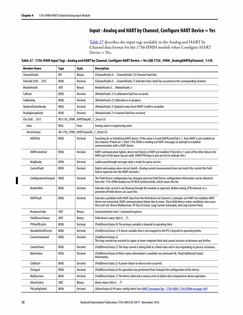
Chapter 4 1756-IF8IH HART Isolated Analog Input Module
Input - Analog and HART by Channel, Configure HART Device = Yes
Table 27 describes the input tags available in the Analog and HART by Channel data format for the 1756-IF8IH module when Configure HART Device = Yes.
Table 27 - 1756-IF8IH Input Tags - Analog and HART by Channel, Configure HART Device = Yes (AB:1756_IF8IH_AnalogHARTbyChannel_1:I:0)
Member Name Type Style Description
ChannelFaults INT Binary (ChannelFaults.0…ChannelFaults.15) Channel Fault Bits.
ChxFault (Ch0…Ch7) BOOL Decimal (ChannelFaults.0…ChannelFaults.7) Indicates that a fault has occurred on the corresponding channel.
ModuleFaults SINT Binary ModuleFaults.0…ModuleFaults.7
CalFault BOOL Decimal (ModuleFaults.1) A calibration fault has occurred.
Calibrating BOOL Decimal (ModuleFaults.2) Calibration is in progress.
UpdatedStatusReady BOOL Decimal (ModuleFaults.3) Updated status from HART Cmd48 is available.
AnalogGroupFault BOOL Decimal (ModuleFaults.7) A channel fault has occurred.
Chx (Ch0…Ch7) AB:1756_IF8IH_HARTDataAll_1_Struct:I:0
Data REAL Float Analog value in engineering units.
DeviceStatus AB:1756_IF8IH_HARTStatusAll_1_Struct:I:0
HARTInit BOOL Decimal Searching for or Initializing HART device. If this value is 0 and HARTCommFail is 1, then HART is not enabled on this channel. If both are 1, then 1756-IF8IH is sending out HART messages to attempt to establish communication with a HART device.
HARTCommFail BOOL Decimal HART communication failure, device not found, or HART not enabled. If this bit is 1, none of the other data in the HART part of the Input Tag are valid. (HART.PVStatus is also set to 0 to indicate this.)
MsgReady BOOL Decimal Ladder passthrough message reply is ready for query service.
CurrentFault BOOL Decimal Digital and analog values do not match. (Analog current measurement does not match the current the Field Device reported over the HART network.)
ConfigurationChanged BOOL Decimal The Field Device configuration has changed and new Field Device configuration information can be obtained from the 1756-IF8IH module via CIP MSG GetDeviceInfo, which clears this bit.
BrokenWire BOOL Decimal Indicates that current is not flowing through the module as expected. Broken wiring, RTB removal, or a powered-off field device can cause this.
HARTFault BOOL Decimal Indicates a problem with HART data from the field device on Channel x. Examples are HART not enabled, HART device not connected, HART communication failure due to noise. These field device status conditions also cause this to be set: Device Malfunction, PV Out of Limits, Loop Current Saturated, and Loop Current Fixed.
ResponseCode SINT Binary Communication error / command response.
FieldDeviceStatus SINT Binary Field device status (bits 0…7).
PVOutOfLimits BOOL Decimal (FieldDeviceStatus.0) The primary variable is beyond its operating limit.
VariableOutOfLimits BOOL Decimal (FieldDeviceStatus.1) A device variable that is not mapped to the PV is beyond its operating limits.
CurrentSaturated BOOL Decimal (FieldDeviceStatus.2) The loop current has reached its upper or lower endpoint limit and cannot increase or decrease any further.
CurrentFixed BOOL Decimal (FieldDeviceStatus.3) The loop current is being held at a fixed value and is not responding to process variations.
MoreStatus BOOL Decimal (FieldDeviceStatus.4) More status information is available via command 48, ‘Read Additional Status’ information.
ColdStart BOOL Decimal (FieldDeviceStatus.5) A power failure or device reset occurred.
Changed BOOL Decimal (FieldDeviceStatus.6) An operation was performed that changed the configuration of the device.
Malfunction BOOL Decimal (FieldDeviceStatus.7) The device detected a serious error or failure that compromises device operation.
AlarmStatus SINT Binary Alarm status (bits 0…7)
PVConfigFailed BOOL Decimal (AlarmStatus.0) PV auto-config failed (See HART Command Tab - 1756-IF8IH, 1756-OF8IH on page 169).
72 Rockwell Automation Publication 1756-UM533E-EN-P - November 2016
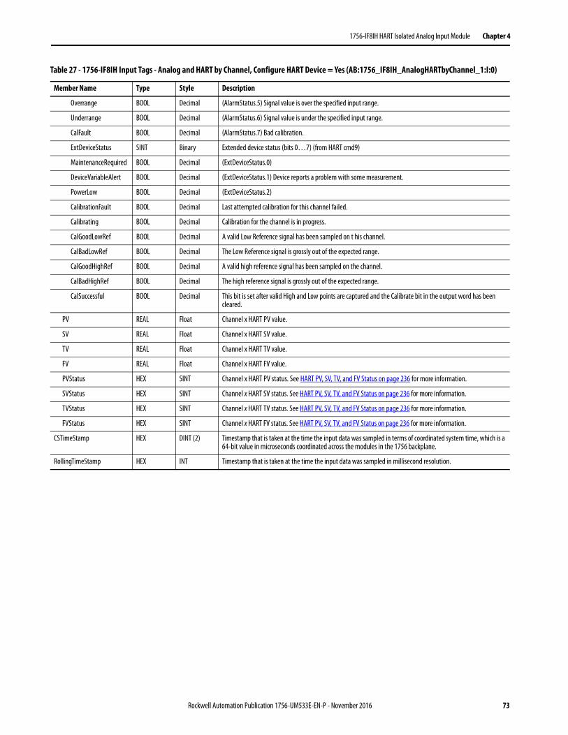
1756-IF8IH HART Isolated Analog Input Module Chapter 4
Overrange BOOL Decimal (AlarmStatus.5) Signal value is over the specified input range.
Underrange BOOL Decimal (AlarmStatus.6) Signal value is under the specified input range.
CalFault BOOL Decimal (AlarmStatus.7) Bad calibration.
ExtDeviceStatus SINT Binary Extended device status (bits 0…7) (from HART cmd9)
MaintenanceRequired BOOL Decimal (ExtDeviceStatus.0)
DeviceVariableAlert BOOL Decimal (ExtDeviceStatus.1) Device reports a problem with some measurement.
PowerLow BOOL Decimal (ExtDeviceStatus.2)
CalibrationFault BOOL Decimal Last attempted calibration for this channel failed.
Calibrating BOOL Decimal Calibration for the channel is in progress.
CalGoodLowRef BOOL Decimal A valid Low Reference signal has been sampled on t his channel.
CalBadLowRef BOOL Decimal The Low Reference signal is grossly out of the expected range.
CalGoodHighRef BOOL Decimal A valid high reference signal has been sampled on the channel.
CalBadHighRef BOOL Decimal The high reference signal is grossly out of the expected range.
CalSuccessful BOOL Decimal This bit is set after valid High and Low points are captured and the Calibrate bit in the output word has been cleared.
PV REAL Float Channel x HART PV value.
SV REAL Float Channel x HART SV value.
TV REAL Float Channel x HART TV value.
FV REAL Float Channel x HART FV value.
PVStatus HEX SINT Channel x HART PV status. See HART PV, SV, TV, and FV Status on page 236 for more information.
SVStatus HEX SINT Channel x HART SV status. See HART PV, SV, TV, and FV Status on page 236 for more information.
TVStatus HEX SINT Channel x HART TV status. See HART PV, SV, TV, and FV Status on page 236 for more information.
FVStatus HEX SINT Channel x HART FV status. See HART PV, SV, TV, and FV Status on page 236 for more information.
CSTimeStamp HEX DINT (2) Timestamp that is taken at the time the input data was sampled in terms of coordinated system time, which is a 64-bit value in microseconds coordinated across the modules in the 1756 backplane.
RollingTimeStamp HEX INT Timestamp that is taken at the time the input data was sampled in millisecond resolution.
Table 27 - 1756-IF8IH Input Tags - Analog and HART by Channel, Configure HART Device = Yes (AB:1756_IF8IH_AnalogHARTbyChannel_1:I:0)
Member Name Type Style Description
Rockwell Automation Publication 1756-UM533E-EN-P - November 2016 73
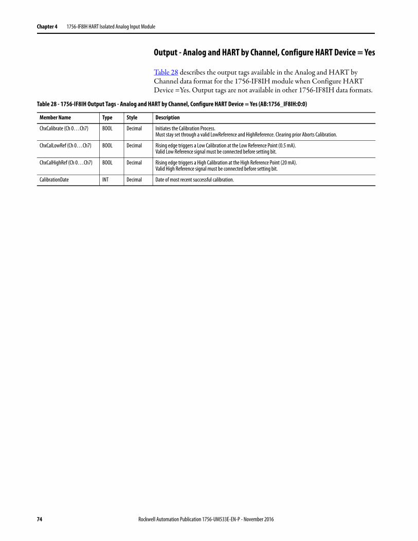
Chapter 4 1756-IF8IH HART Isolated Analog Input Module
Output - Analog and HART by Channel, Configure HART Device = Yes
Table 28 describes the output tags available in the Analog and HART by Channel data format for the 1756-IF8IH module when Configure HART Device =Yes. Output tags are not available in other 1756-IF8IH data formats.
Table 28 - 1756-IF8IH Output Tags - Analog and HART by Channel, Configure HART Device = Yes (AB:1756_IF8IH:O:0)
Member Name Type Style Description
ChxCalibrate (Ch 0…Ch7) BOOL Decimal Initiates the Calibration Process.Must stay set through a valid LowReference and HighReference. Clearing prior Aborts Calibration.
ChxCalLowRef (Ch 0…Ch7) BOOL Decimal Rising edge triggers a Low Calibration at the Low Reference Point (0.5 mA).Valid Low Reference signal must be connected before setting bit.
ChxCalHighRef (Ch 0…Ch7) BOOL Decimal Rising edge triggers a High Calibration at the High Reference Point (20 mA).Valid High Reference signal must be connected before setting bit.
CalibrationDate INT Decimal Date of most recent successful calibration.
74 Rockwell Automation Publication 1756-UM533E-EN-P - November 2016
Chapter 5
1756-IF16H HART Analog Input Module
This chapter discusses these topics.
Module Features The 1756-IF16H module has the following features:• Choice of three data formats
• Analog only• Analog and HART PV• Analog and HART by channel
• 0…20 mA or 4…20 mA input ranges• Module filter• Real-time sampling• Underrange and overrange detection• Wire-off detection • Highway addressable remote transducer (HART) communication
Topic Page
Module Features 75
Wire the Module 80
Circuit Diagram 82
1756-IF16H Module Fault and Status Reporting 83
Module-defined Data Types, 1756-IF16H Module 86
Rockwell Automation Publication 1756-UM533E-EN-P - November 2016 75
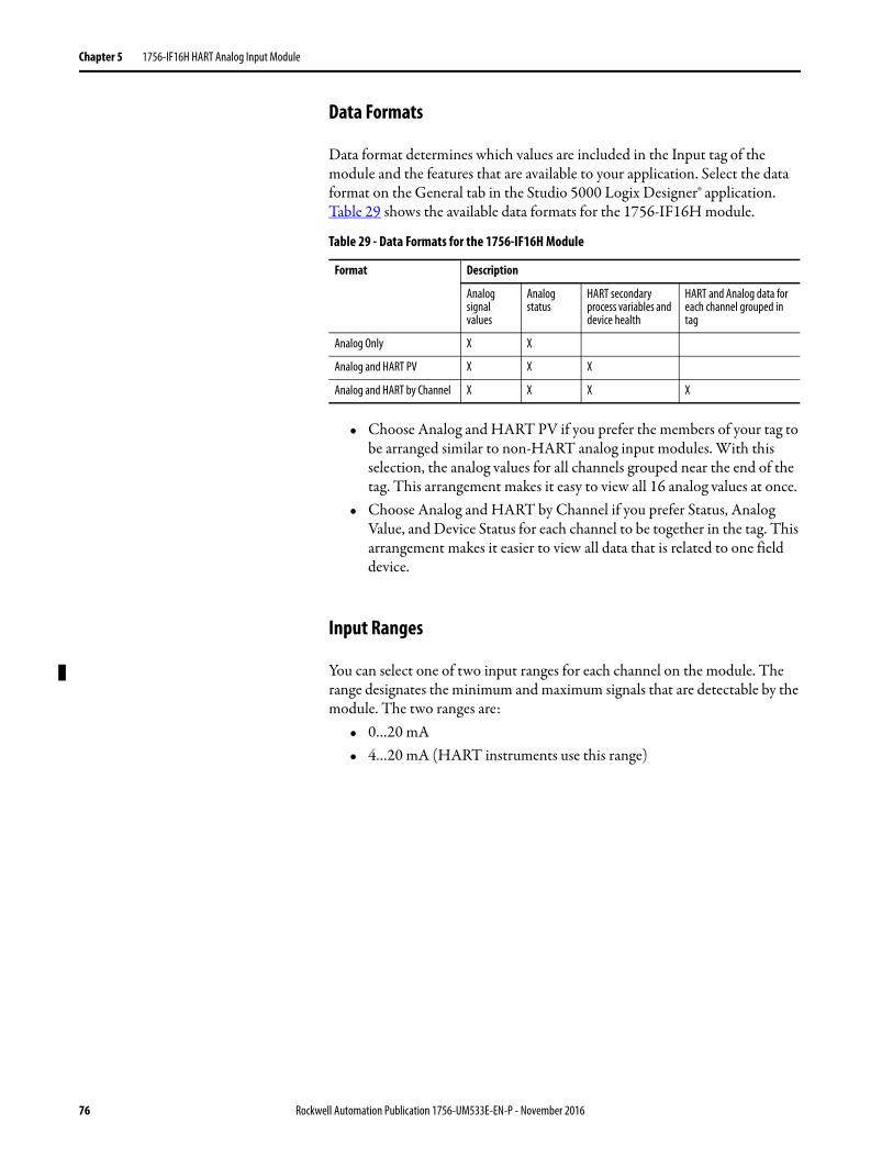
Chapter 5 1756-IF16H HART Analog Input Module
Data Formats
Data format determines which values are included in the Input tag of the module and the features that are available to your application. Select the data format on the General tab in the Studio 5000 Logix Designer® application. Table 29 shows the available data formats for the 1756-IF16H module.
• Choose Analog and HART PV if you prefer the members of your tag to be arranged similar to non-HART analog input modules. With this selection, the analog values for all channels grouped near the end of the tag. This arrangement makes it easy to view all 16 analog values at once.
• Choose Analog and HART by Channel if you prefer Status, Analog Value, and Device Status for each channel to be together in the tag. This arrangement makes it easier to view all data that is related to one field device.
Input Ranges
You can select one of two input ranges for each channel on the module. The range designates the minimum and maximum signals that are detectable by the module. The two ranges are:
• 0…20 mA• 4…20 mA (HART instruments use this range)
Table 29 - Data Formats for the 1756-IF16H Module
Format Description
Analog signal values
Analog status
HART secondary process variables and device health
HART and Analog data for each channel grouped in tag
Analog Only X X
Analog and HART PV X X X
Analog and HART by Channel X X X X
76 Rockwell Automation Publication 1756-UM533E-EN-P - November 2016
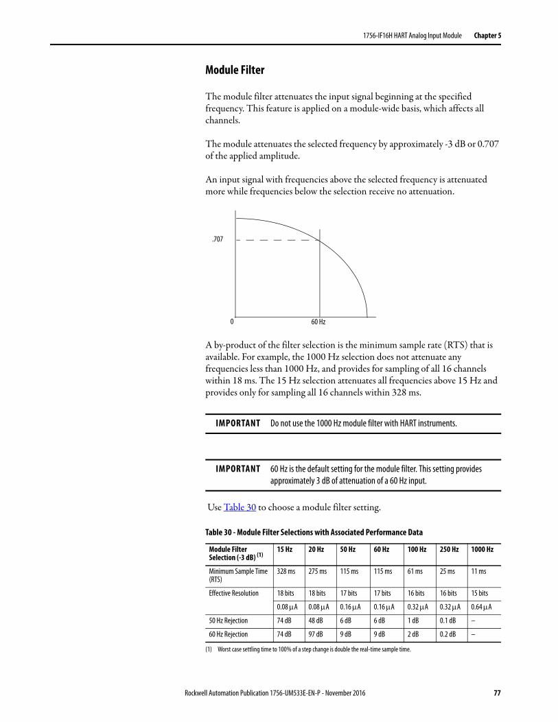
1756-IF16H HART Analog Input Module Chapter 5
Module Filter
The module filter attenuates the input signal beginning at the specified frequency. This feature is applied on a module-wide basis, which affects all channels.
The module attenuates the selected frequency by approximately -3 dB or 0.707 of the applied amplitude.
An input signal with frequencies above the selected frequency is attenuated more while frequencies below the selection receive no attenuation.
A by-product of the filter selection is the minimum sample rate (RTS) that is available. For example, the 1000 Hz selection does not attenuate any frequencies less than 1000 Hz, and provides for sampling of all 16 channels within 18 ms. The 15 Hz selection attenuates all frequencies above 15 Hz and provides only for sampling all 16 channels within 328 ms.
Use Table 30 to choose a module filter setting.
IMPORTANT Do not use the 1000 Hz module filter with HART instruments.
IMPORTANT 60 Hz is the default setting for the module filter. This setting provides approximately 3 dB of attenuation of a 60 Hz input.
Table 30 - Module Filter Selections with Associated Performance Data
Module Filter Selection (-3 dB) (1)
(1) Worst case settling time to 100% of a step change is double the real-time sample time.
15 Hz 20 Hz 50 Hz 60 Hz 100 Hz 250 Hz 1000 Hz
Minimum Sample Time (RTS)
328 ms 275 ms 115 ms 115 ms 61 ms 25 ms 11 ms
Effective Resolution 18 bits 18 bits 17 bits 17 bits 16 bits 16 bits 15 bits
0.08 A 0.08 A 0.16 A 0.16 A 0.32 A 0.32 A 0.64 A
50 Hz Rejection 74 dB 48 dB 6 dB 6 dB 1 dB 0.1 dB –
60 Hz Rejection 74 dB 97 dB 9 dB 9 dB 2 dB 0.2 dB –
.707
60 Hz0
Rockwell Automation Publication 1756-UM533E-EN-P - November 2016 77
Chapter 5 1756-IF16H HART Analog Input Module
Real-time Sampling (RTS)
This parameter instructs the module how often to scan its input channels and obtain all available data. After the channels are scanned, the module multicasts that data. This feature is applied on a module-wide basis.
During module configuration, you specify a real-time sampling (RTS) period and a requested packet interval (RPI) period. Both of these features instruct the module to multicast data, but only the RTS feature instructs the module to scan its channels before multicasting.
Underrange and Overrange Detection
The module detects when it is operating beyond limits of the input range. This status indication tells you that the input signal is not being measured accurately because the signal is beyond the measuring capability of the module. For example, the module cannot distinguish between 20.5 mA and 22 mA
Table 31 shows the input ranges of the 1756-IF16H module and the lowest and highest signal available in each range before the module detects an underrange and overrange condition.
Table 31 - Low and High Signal Limits on the 1756-IF16H Module
Module Available Range Lowest Signal in Range Highest Signal in Range
1756-IF16H 0…20 mA 0 mA 20.58 mA
4…20 mA 3.42 mA 20.58 mA
78 Rockwell Automation Publication 1756-UM533E-EN-P - November 2016
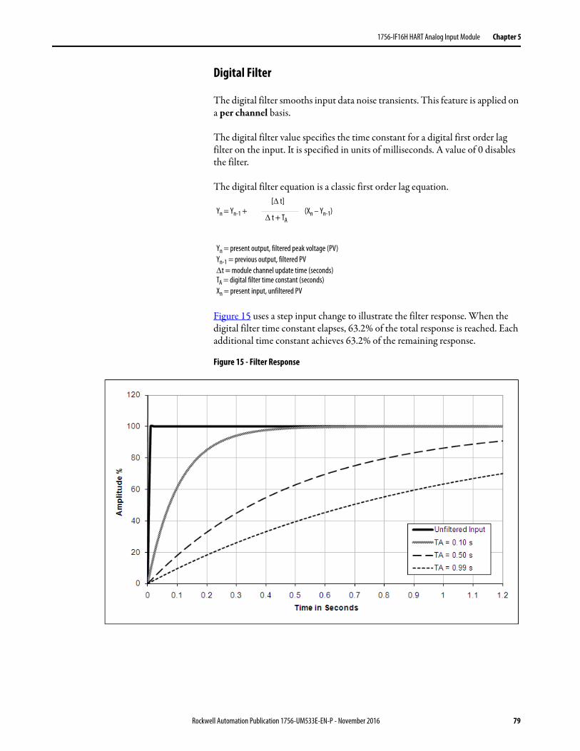
1756-IF16H HART Analog Input Module Chapter 5
Digital Filter
The digital filter smooths input data noise transients. This feature is applied on a per channel basis.
The digital filter value specifies the time constant for a digital first order lag filter on the input. It is specified in units of milliseconds. A value of 0 disables the filter.
The digital filter equation is a classic first order lag equation.
Figure 15 uses a step input change to illustrate the filter response. When the digital filter time constant elapses, 63.2% of the total response is reached. Each additional time constant achieves 63.2% of the remaining response.
Figure 15 - Filter Response
Yn = Yn-1 + (Xn – Yn-1)[ t]
t + TA
Yn = present output, filtered peak voltage (PV)Yn-1 = previous output, filtered PVt = module channel update time (seconds)TA = digital filter time constant (seconds)Xn = present input, unfiltered PV
Rockwell Automation Publication 1756-UM533E-EN-P - November 2016 79
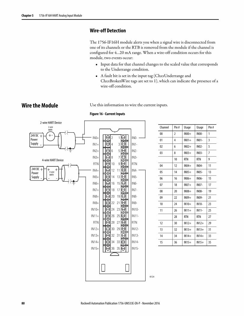
Chapter 5 1756-IF16H HART Analog Input Module
Wire-off Detection
The 1756-IF16H module alerts you when a signal wire is disconnected from one of its channels or the RTB is removed from the module if the channel is configured for 4…20 mA range. When a wire-off condition occurs for this module, two events occur:
• Input data for that channel changes to the scaled value that corresponds to the Underrange condition.
• A fault bit is set in the input tag (ChxxUnderrange and ChxxBrokenWire tags are set to 1), which can indicate the presence of a wire-off condition.
Wire the Module Use this information to wire the current inputs.
Figure 16 - Current Inputs
+
-
+
-
+
- -
+ -IN0+
IN1+
IN2+
IN3+
RTN
IN4+
IN5+
IN6+
IN7+
IN8+
IN9+
IN10+
IN11+
RTN
IN12+
IN13+
IN14+
IN15+
IN0-
IN1-
IN2-
IN3-
RTN
IN4-
IN5-
IN6-
IN7-
IN8-
IN9-
IN10-
IN11-
RTN
IN12-
IN13-
IN14-
IN15-
2
4
6
8
10
12
14
16
18
20
22
24
26
28
30
32
34
36
1
3
5
7
9
11
13
15
17
19
21
23
25
27
29
31
33
35
+
45124
Channel Pin # Usage Usage Pin #
00 2 IN00+ IN00- 1
01 4 IN01+ IN01- 3
02 6 IN02+ IN02- 5
03 8 IN03+ IN03- 7
10 RTN RTN 9
04 12 IN04+ IN04- 11
05 14 IN05+ IN05- 13
06 16 IN06+ IN06- 15
07 18 IN07+ IN07- 17
08 20 IN08+ IN08- 19
09 22 IN09+ IN09- 21
10 24 IN10+ IN10- 23
11 26 IN11+ IN11- 25
28 RTN RTN 27
12 30 IN12+ IN12+ 29
13 32 IN13+ IN13+ 31
14 34 IN14+ IN14+ 33
15 36 IN15+ IN15+ 35
4-wire XMTR
2-wire XMTR
2-wire HART Device
4-wire HART Device
24V DC Power Supply
24V DC Power Supply
80 Rockwell Automation Publication 1756-UM533E-EN-P - November 2016
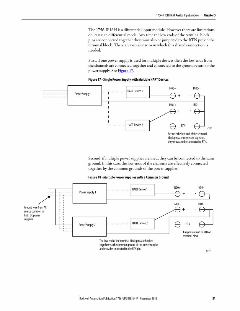
1756-IF16H HART Analog Input Module Chapter 5
The 1756-IF16H is a differential input module. However there are limitations on its use in differential mode. Any time the low ends of the terminal block pins are connected together they must also be jumpered to the RTN pin on the terminal block. There are two scenarios in which this shared connection is needed.
First, if one power supply is used for multiple devices then the low ends from the channels are connected together and connected to the ground return of the power supply. See Figure 17.
Figure 17 - Single Power Supply with Multiple HART Devices
Second, if multiple power supplies are used, they can be connected to the same ground. In this case, the low ends of the channels are effectively connected together by the common grounds of the power supplies.
Figure 18 - Multiple Power Supplies with a Common Ground
Power Supply 1HART Device 1
HART Device 2
+ -
+ -
RTN
Because the low end of the terminal block pins are connected together, they must also be connected to RTN.
45120
IN00+ IN00-
IN01+ IN01-
Ground wire from AC source common to both DC power supplies
Power Supply 1
Power Supply 2
The low end of the terminal block pins are hooked together via the common ground of the power supples and must be connected to the RTN pin.
HART Device 1
HART Device 2
+ -
+ -
RTN
Jumper low end to RTN on terminal block
45119
IN00+ IN00-
IN01+ IN01-
Rockwell Automation Publication 1756-UM533E-EN-P - November 2016 81
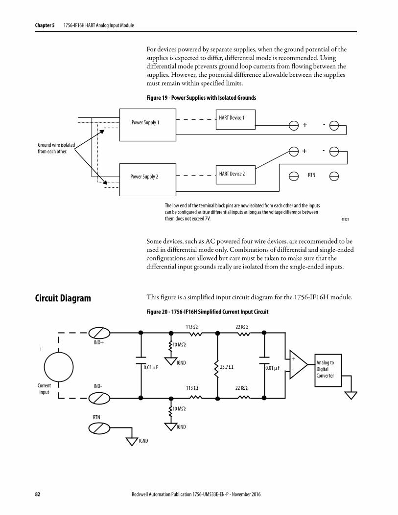
Chapter 5 1756-IF16H HART Analog Input Module
For devices powered by separate supplies, when the ground potential of the supplies is expected to differ, differential mode is recommended. Using differential mode prevents ground loop currents from flowing between the supplies. However, the potential difference allowable between the supplies must remain within specified limits.
Figure 19 - Power Supplies with Isolated Grounds
Some devices, such as AC powered four wire devices, are recommended to be used in differential mode only. Combinations of differential and single-ended configurations are allowed but care must be taken to make sure that the differential input grounds really are isolated from the single-ended inputs.
Circuit Diagram This figure is a simplified input circuit diagram for the 1756-IF16H module.
Figure 20 - 1756-IF16H Simplified Current Input Circuit
Ground wire isolated from each other.
Power Supply 1
Power Supply 2
The low end of the terminal block pins are now isolated from each other and the inputs can be configured as true differential inputs as long as the voltage difference between them does not exceed 7V.
HART Device 1
HART Device 2
+ -
+ -
RTN
45121
23.7 Analog to Digital Converter
22 K
RTN
IGND
+
-0.01 F
113
10 MINO+
INO-Current Input
i
22 K
113
IGND0.01 F
10 M
IGND
82 Rockwell Automation Publication 1756-UM533E-EN-P - November 2016
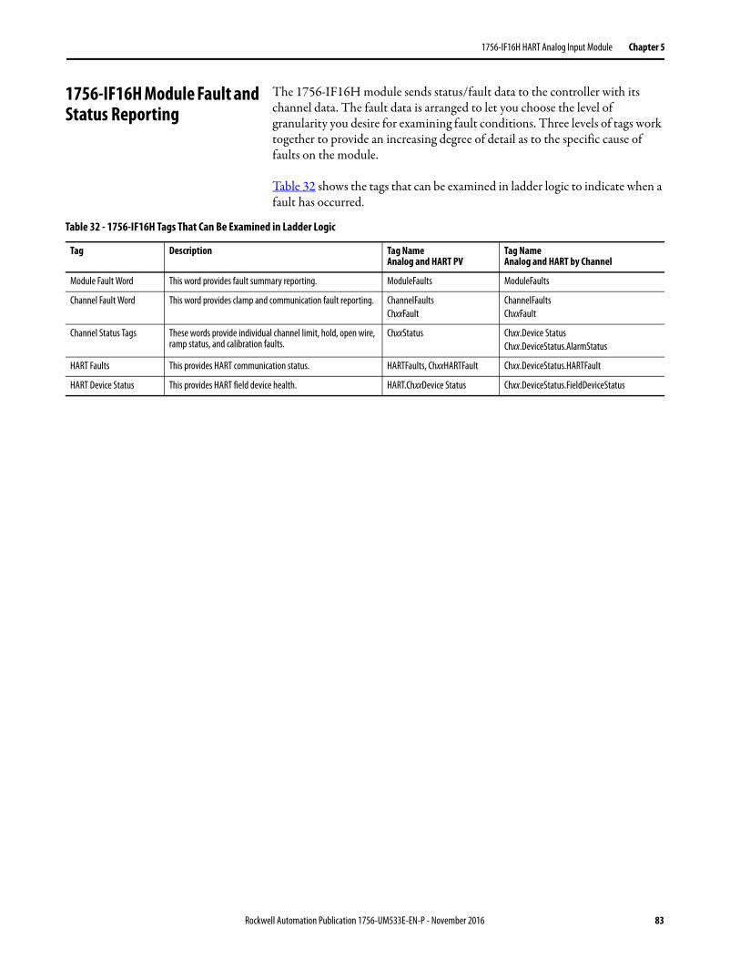
1756-IF16H HART Analog Input Module Chapter 5
1756-IF16H Module Fault and Status Reporting
The 1756-IF16H module sends status/fault data to the controller with its channel data. The fault data is arranged to let you choose the level of granularity you desire for examining fault conditions. Three levels of tags work together to provide an increasing degree of detail as to the specific cause of faults on the module.
Table 32 shows the tags that can be examined in ladder logic to indicate when a fault has occurred.
Table 32 - 1756-IF16H Tags That Can Be Examined in Ladder Logic
Tag Description Tag NameAnalog and HART PV
Tag NameAnalog and HART by Channel
Module Fault Word This word provides fault summary reporting. ModuleFaults ModuleFaults
Channel Fault Word This word provides clamp and communication fault reporting. ChannelFaultsChxxFault
ChannelFaultsChxxFault
Channel Status Tags These words provide individual channel limit, hold, open wire, ramp status, and calibration faults.
ChxxStatus Chxx.Device StatusChxx.DeviceStatus.AlarmStatus
HART Faults This provides HART communication status. HARTFaults, ChxxHARTFault Chxx.DeviceStatus.HARTFault
HART Device Status This provides HART field device health. HART.ChxxDevice Status Chxx.DeviceStatus.FieldDeviceStatus
Rockwell Automation Publication 1756-UM533E-EN-P - November 2016 83
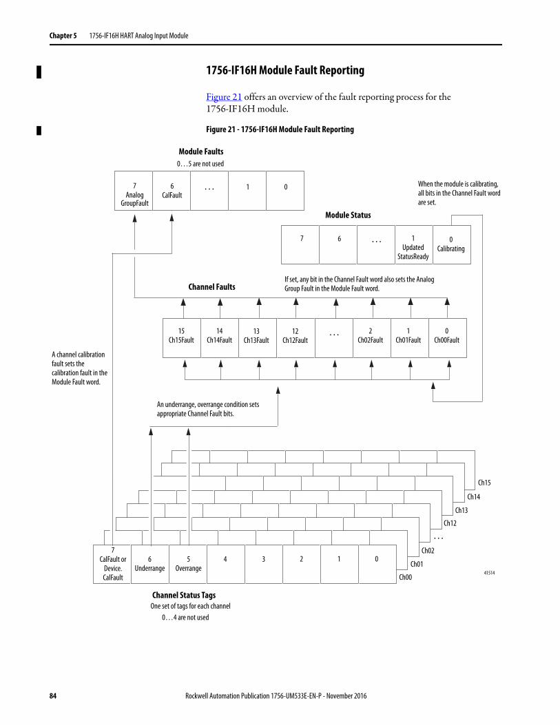
Chapter 5 1756-IF16H HART Analog Input Module
1756-IF16H Module Fault Reporting
Figure 21 offers an overview of the fault reporting process for the 1756-IF16H module.
Figure 21 - 1756-IF16H Module Fault Reporting
If set, any bit in the Channel Fault word also sets the Analog Group Fault in the Module Fault word.
A channel calibration fault sets the calibration fault in the Module Fault word.
An underrange, overrange condition sets appropriate Channel Fault bits.
When the module is calibrating, all bits in the Channel Fault word are set.
0…4 are not used
41514
One set of tags for each channel
Module Faults
Channel Faults
Channel Status Tags
7Analog
GroupFault
1 0
0…5 are not used
15Ch15Fault
14Ch14Fault
13Ch13Fault
12Ch12Fault
… 2Ch02Fault
1Ch01Fault
0Ch00Fault
7CalFault or
Device.CalFault
6Underrange
5Overrange
4 3 2 1 0
Ch00
Ch01
Ch02
…Ch12
Ch13
Ch14
Ch15
6CalFault
…
Module Status
7 0Calibrating
6 … 1Updated
StatusReady
84 Rockwell Automation Publication 1756-UM533E-EN-P - November 2016
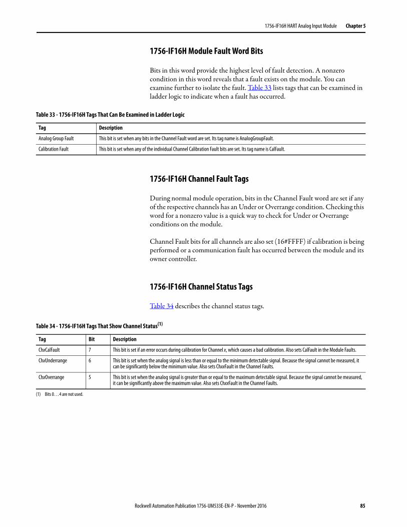
1756-IF16H HART Analog Input Module Chapter 5
1756-IF16H Module Fault Word Bits
Bits in this word provide the highest level of fault detection. A nonzero condition in this word reveals that a fault exists on the module. You can examine further to isolate the fault. Table 33 lists tags that can be examined in ladder logic to indicate when a fault has occurred.
1756-IF16H Channel Fault Tags
During normal module operation, bits in the Channel Fault word are set if any of the respective channels has an Under or Overrange condition. Checking this word for a nonzero value is a quick way to check for Under or Overrange conditions on the module.
Channel Fault bits for all channels are also set (16#FFFF) if calibration is being performed or a communication fault has occurred between the module and its owner controller.
1756-IF16H Channel Status Tags
Table 34 describes the channel status tags.
Table 33 - 1756-IF16H Tags That Can Be Examined in Ladder Logic
Tag Description
Analog Group Fault This bit is set when any bits in the Channel Fault word are set. Its tag name is AnalogGroupFault.
Calibration Fault This bit is set when any of the individual Channel Calibration Fault bits are set. Its tag name is CalFault.
Table 34 - 1756-IF16H Tags That Show Channel Status(1)
Tag Bit Description
ChxCalFault 7 This bit is set if an error occurs during calibration for Channel x, which causes a bad calibration. Also sets CalFault in the Module Faults.
ChxUnderrange 6 This bit is set when the analog signal is less than or equal to the minimum detectable signal. Because the signal cannot be measured, it can be significantly below the minimum value. Also sets ChxxFault in the Channel Faults.
ChxOverrange 5 This bit is set when the analog signal is greater than or equal to the maximum detectable signal. Because the signal cannot be measured, it can be significantly above the maximum value. Also sets ChxxFault in the Channel Faults.
(1) Bits 0…4 are not used.
Rockwell Automation Publication 1756-UM533E-EN-P - November 2016 85
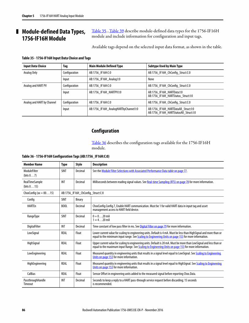
Chapter 5 1756-IF16H HART Analog Input Module
Module-defined Data Types, 1756-IF16H Module
Table 35…Table 39 describe module-defined data types for the 1756-IF16H module and include information for configuration and input tags.
Available tags depend on the selected input data format, as shown in the table.
Configuration
Table 36 describes the configuration tags available for the 1756-IF16H module.
Table 35 - 1756-IF16H Input Data Choice and Tags
Input Data Choice Tag Main Module Defined Type Subtype Used by Main Type
Analog Only Configuration AB:1756_IF16H:C:0 AB:1756_IF16H_ChConfig_Struct:C:0
Input AB:1756_IF16H_Analog:I:0 None
Analog and HART PV Configuration AB:1756_IF16H:C:0 AB:1756_IF16H_ChConfig_Struct:C:0
Input AB:1756_IF16H_HARTPV:I:0 AB:1756_IF16H_HARTData:I:0AB:1756_IF16H_HARTStatus_Struct:I:0
Analog and HART by Channel Configuration AB:1756_IF16H:C:0 AB:1756_IF16H_ChConfig_Struct:C:0
Input AB:1756_IF16H_AnalogHARTbyChannel:I:0 AB:1756_IF16H_HARTDataAll_Struct:I:0AB:1756_IF16H_HARTStatusAll_Struct:I:0
Table 36 - 1756-IF16H Configuration Tags (AB:1756_IF16H:C:0)
Member Name Type Style Description
ModuleFilter(bits 0…7)
SINT Decimal See the Module Filter Selections with Associated Performance Data table on page 77.
RealTimeSample(bits 0…15)
INT Decimal Milliseconds between reading signal values. See Real-time Sampling (RTS) on page 78 for more information.
ChxxConfig (xx = 00…15) AB:1756_IF16H_ChConfig_Struct:C:0
Config SINT Binary
HARTEn BOOL Decimal ChxxConfig.Config.7, Enable HART communication. Must be 1 for valid HART data in input tag and asset management access to HART field device.
RangeType SINT Decimal 0 = 0…20 mA1 = 4…20 mA
DigitalFilter INT Decimal Time constant of low pass filter in ms. See Digital Filter on page 79 for more information.
LowSignal REAL Float Lower current value for scaling to engineering units. Default is 4 mA. Must be less than HighSignal and more than or equal to the minimum input range. See Scaling to Engineering Units on page 153 for more information.
HighSignal REAL Float Upper current value for scaling to engineering units. Default is 20 mA. Must be more than LowSignal and less than or equal to the maximum input Range. See Scaling to Engineering Units on page 153 for more information.
LowEngineering REAL Float Measured quantity in engineering units that results in a signal level equal to LowSignal. See Scaling to Engineering Units on page 153 for more information.
HighEngineering REAL Float Measured quantity in engineering units that results in a signal level equal to HighSignal. See Scaling to Engineering Units on page 153 for more information.
CalBias REAL Float Sensor Offset in engineering units added to the measured signal before reporting Chxx.Data.
PassthroughHandleTimeout
INT Decimal Seconds to keep a reply to a HART pass-through service request before discarding; 15 secondsis recommended.
86 Rockwell Automation Publication 1756-UM533E-EN-P - November 2016
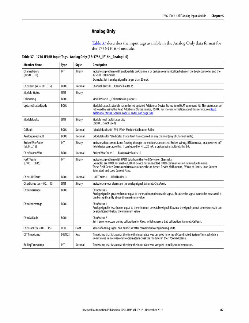
1756-IF16H HART Analog Input Module Chapter 5
Analog Only
Table 37 describes the input tags available in the Analog Only data format for the 1756-IF16H module.
Table 37 - 1756-IF16H Input Tags - Analog Only (AB:1756_IF16H_Analog:I:0)
Member Name Type Style Description
ChannelFaults(bits 0…15)
INT Binary Indicates a problem with analog data on Channel x or broken communication between the Logix controller and the 1756-IF16H module.Example: Set if analog signal is larger than 20 mA.
ChxxFault (xx = 00…15) BOOL Decimal ChannelFaults.0…ChannelFaults.15
Module Status SINT Binary
Calibrating BOOL ModuleStatus.0, Calibration in progress
UpdatedStatusReady BOOL ModuleStatus.1, Module has collected updated Additional Device Status from HART command 48. This status can be retrieved by using the Read Additional Status service, 16#4C. For more information about this service, see Read Additional Status (Service Code = 16#4C) on page 181.
ModuleFaults SINT Binary Module level fault status bits (bits 0…5 not used)
CalFault BOOL Decimal (ModuleFaults.6) 1756-IF16H Module Calibration Failed.
AnalogGroupFault BOOL Decimal (ModuleFaults.7) Indicates that a fault has occurred on any channel (any of ChannelFaults).
BrokenWireFaults(bit 0…15)
INT Binary Indicates that current is not flowing through the module as expected. Broken wiring, RTB removal, or a powered-off field device can cause this. If configured for 4…20 mA, a broken wire fault sets this bit.
ChxxBroken Wire BOOL Decimal BrokenWireFaults.0…BrokenWireFaults.15
HARTFaults(Ch00…Ch15)
INT Binary Indicates a problem with HART data from the Field Device on Channel x. Examples are HART not enabled, HART device not connected, HART communication failure due to noise.These Field Device Status conditions also cause this to be set: Device Malfunction, PV Out of Limits, Loop Current Saturated, and Loop Current Fixed.
ChxxHARTFault BOOL Decimal HARTFaults.0…HARTFaults.15
ChxxStatus (xx = 00…15) SINT Binary Indicates various alarms on the analog signal. Also sets ChxxFault.
ChxxOverrange BOOL ChxxStatus.5 Analog signal is greater than or equal to the maximum detectable signal. Because the signal cannot be measured, it can be significantly above the maximum value.
ChxxUnderrange BOOL ChxxStatus.6 Analog signal is less than or equal to the minimum detectable signal. Because the signal cannot be measured, it can be significantly below the minimum value.
ChxxCalFault BOOL ChxxStatus.7 Set if an error occurs during calibration for Chxx, which causes a bad calibration. Also sets CalFault.
ChxxData (xx = 00…15) REAL Float Value of analog signal on Channel xx after conversion to engineering units.
CSTTimestamp DINT[2] Hex Timestamp that is taken at the time the input data was sampled in terms of Coordinated System Time, which is a 64-bit value in microseconds coordinated across the modules in the 1756 backplane.
RollingTimestamp INT Decimal Timestamp that is taken at the time the input data was sampled in millisecond resolution.
Rockwell Automation Publication 1756-UM533E-EN-P - November 2016 87

Chapter 5 1756-IF16H HART Analog Input Module
Analog and HART PV
Table 38 describes the input tags available in the Analog and HART PV data format for the 1756-IF16H module.
Table 38 - 1756-IF16H Input Tags - Analog and HART PV (AB:1756_IF16H_HARTPV:I:0)
Member Name Type Style Description
ChannelFaults(bit0…15)
INT Binary Indicates a problem with analog data on Channel x or broken communication between the Logix controller and the 1756-IF16H module.Example: Set if analog signal is larger than 20 mA.
ChxxFault (xx = 00…15) BOOL Decimal ChannelFaults.0…ChannelFaults.15
ModuleStatus SINT Binary
Calibrating BOOL (ModuleStatus.0) Calibration in progress.
UpdatedStatusReady BOOL (ModuleStatus.1) Module has collected updated Additional Device Status from HART command 48. This status can be retrieved by using the Read Additional Status service, 16#4C. For more information about this service, see Read Additional Status (Service Code = 16#4C) on page 181.
ModuleFaults SINT Binary (bits0…5 not used)
CalFault BOOL Decimal (ModuleFaults.6) 1756-IF16H Module Calibration Failed.
AnalogGroupFault BOOL Decimal (ModuleFaults.7) Indicates that a fault has occurred on any channel (any of ChannelFaults).
BrokenWireFaults(bit 0…15)
INT Binary Indicates that current is not flowing through the module as expected. Broken wiring, RTB removal, or a powered-off field device can cause this.
ChxxBroken Wire BOOL Decimal BrokenWireFaults.0…BrokenWireFaults.15
HARTFaults INT Binary Indicates a problem with HART data from the Field Device on Channel x. Examples are HART not enabled, HART device not connected, HART communication failure due to noise.These Field Device Status conditions also cause this to be set: Device Malfunction, PV Out of Limits, Loop Current Saturated, and Loop Current Fixed.
ChxxHARTFault BOOL Decimal HARTFaults.0…HARTFaults.15
ChxxStatus (xx = 00…15) SINT Binary Indicates various alarms on the analog signal. Also sets ChxxFault for Overrange, Underrange, and/or CalFault.
ChxxOverrange BOOL (ChxxStatus.05) Analog signal is greater than or equal to the maximum detectable signal. Because the signal cannot be measured, it can be significantly above the maximum value.
ChxxUnderrange BOOL (ChxxStatus.06) Analog signal is less than or equal to the minimum detectable signal. Because the signal cannot be measured, it can be significantly below the minimum value.
ChxxCalFault BOOL (ChxxStatus.07)Set if an error occurs during calibration for Channel x, which causes a bad calibration. Also sets CalFault.
ChxxData (xx = 00…15) REAL Float Value of analog signal on Channel xx after conversion to engineering units.
CSTTimestamp DINT[2] Hex Timestamp that is taken at the time the input data was sampled in terms of Coordinated System Time, which is a 64-bit value in microseconds coordinated across the modules in the 1756 backplane.
RollingTimestamp INT Decimal Timestamp that is taken at the time the input data was sampled in millisecond resolution.
HART AB:1756_IF16H_HARTData:I:0, Contains HART field device health and dynamic process variables.
ChxxDeviceStatus (xx = 00…15)
AB:1756_IF16H_HARTStatus_Struct:I:0, Channel 0 HART Device status info.
Init BOOL Searching for or Initializing HART device. If this value is 0 and Fail is 1, then HART is not Enabled on this channel. If both are 1, then 1756-IF16H is sending out HART messages to attempt to establish communication with a HART device.
Fail BOOL HART communication failure or device not found or HART not enabled. If this bit is 1, none of the other data in the HART part of the Input Tag are valid. (HART.PVStatus is also set to 0 to indicate this.)
MsgReady BOOL Pass-through message reply is ready for Query service.
88 Rockwell Automation Publication 1756-UM533E-EN-P - November 2016
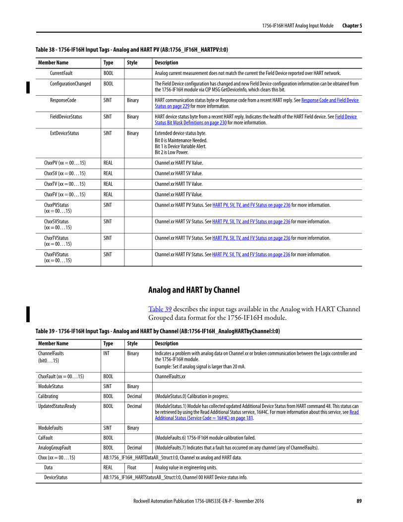
1756-IF16H HART Analog Input Module Chapter 5
Analog and HART by Channel
Table 39 describes the input tags available in the Analog with HART Channel Grouped data format for the 1756-IF16H module.
CurrentFault BOOL Analog current measurement does not match the current the Field Device reported over HART network.
ConfigurationChanged BOOL The Field Device configuration has changed and new Field Device configuration information can be obtained from the 1756-IF16H module via CIP MSG GetDeviceInfo, which clears this bit.
ResponseCode SINT Binary HART communication status byte or Response code from a recent HART reply. See Response Code and Field Device Status on page 229 for more information.
FieldDeviceStatus SINT Binary HART device status byte from a recent HART reply. Indicates the health of the HART Field device. See Field Device Status Bit Mask Definitions on page 230 for more information.
ExtDeviceStatus SINT Binary Extended device status byte.Bit 0 is Maintenance Needed.Bit 1 is Device Variable Alert.Bit 2 is Low Power.
ChxxPV (xx = 00…15) REAL Channel xx HART PV Value.
ChxxSV (xx = 00…15) REAL Channel xx HART SV Value.
ChxxTV (xx = 00…15) REAL Channel xx HART TV Value.
ChxxFV (xx = 00…15) REAL Channel xx HART FV Value.
ChxxPVStatus (xx = 00…15)
SINT Channel xx HART PV Status. See HART PV, SV, TV, and FV Status on page 236 for more information.
ChxxSVStatus(xx = 00…15)
SINT Channel xx HART SV Status. See HART PV, SV, TV, and FV Status on page 236 for more information.
ChxxTVStatus(xx = 00…15)
SINT Channel xx HART TV Status. See HART PV, SV, TV, and FV Status on page 236 for more information.
ChxxFVStatus(xx = 00…15)
SINT Channel xx HART FV Status. See HART PV, SV, TV, and FV Status on page 236 for more information.
Table 38 - 1756-IF16H Input Tags - Analog and HART PV (AB:1756_IF16H_HARTPV:I:0)
Member Name Type Style Description
Table 39 - 1756-IF16H Input Tags - Analog and HART by Channel (AB:1756-IF16H_AnalogHARTbyChannel:I:0)
Member Name Type Style Description
ChannelFaults(bit0…15)
INT Binary Indicates a problem with analog data on Channel xx or broken communication between the Logix controller and the 1756-IF16H module.Example: Set if analog signal is larger than 20 mA.
ChxxFault (xx = 00…15) BOOL ChannelFaults.xx
ModuleStatus SINT Binary
Calibrating BOOL Decimal (ModuleStatus.0) Calibration in progress.
UpdatedStatusReady BOOL Decimal (ModuleStatus.1) Module has collected updated Additional Device Status from HART command 48. This status can be retrieved by using the Read Additional Status service, 16#4C. For more information about this service, see Read Additional Status (Service Code = 16#4C) on page 181.
ModuleFaults SINT Binary
CalFault BOOL (ModuleFaults.6) 1756-IF16H module calibration failed.
AnalogGroupFault BOOL Decimal (ModuleFaults.7) Indicates that a fault has occurred on any channel (any of ChannelFaults).
Chxx (xx = 00…15) AB:1756_IF16H_HARTDataAll_Struct:I:0, Channel xx analog and HART data.
Data REAL Float Analog value in engineering units.
DeviceStatus AB:1756_IF16H_HARTStatusAll_Struct:I:0, Channel 00 HART Device status info.
Rockwell Automation Publication 1756-UM533E-EN-P - November 2016 89
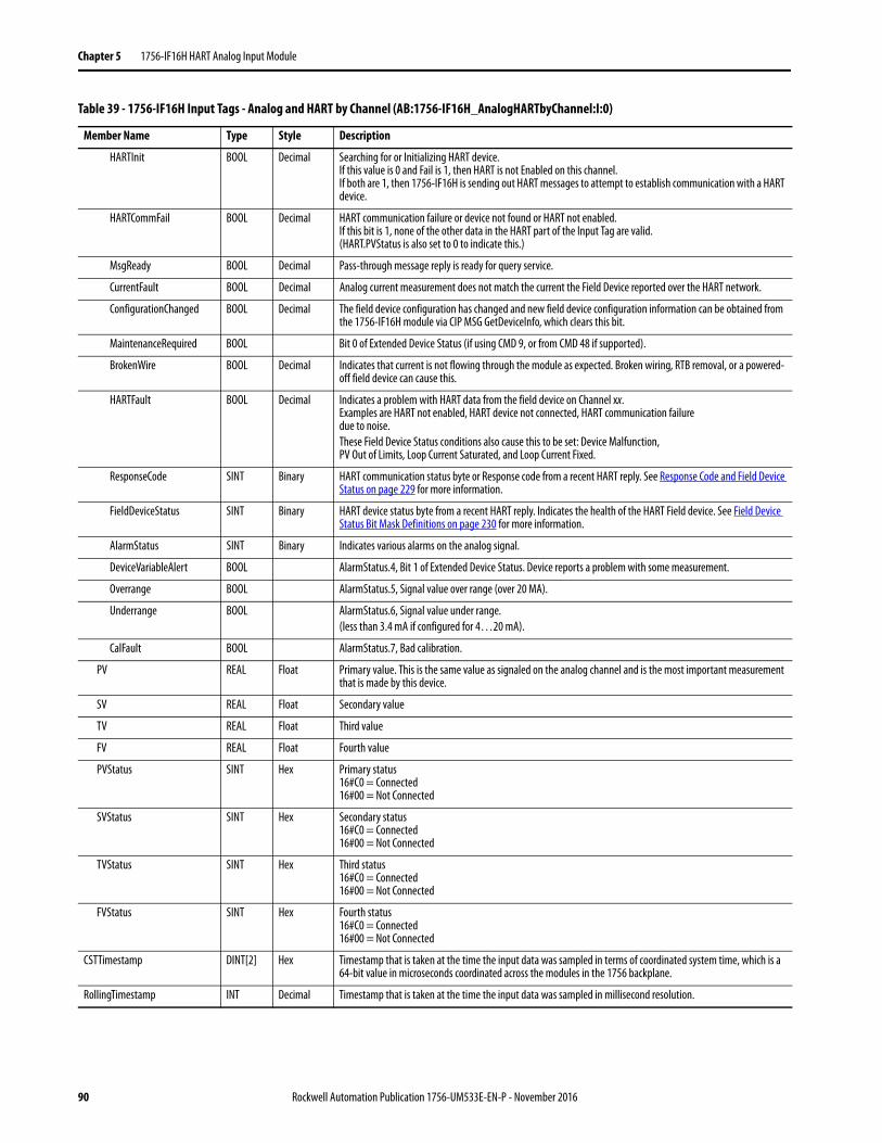
Chapter 5 1756-IF16H HART Analog Input Module
HARTInit BOOL Decimal Searching for or Initializing HART device. If this value is 0 and Fail is 1, then HART is not Enabled on this channel. If both are 1, then 1756-IF16H is sending out HART messages to attempt to establish communication with a HART device.
HARTCommFail BOOL Decimal HART communication failure or device not found or HART not enabled. If this bit is 1, none of the other data in the HART part of the Input Tag are valid. (HART.PVStatus is also set to 0 to indicate this.)
MsgReady BOOL Decimal Pass-through message reply is ready for query service.
CurrentFault BOOL Decimal Analog current measurement does not match the current the Field Device reported over the HART network.
ConfigurationChanged BOOL Decimal The field device configuration has changed and new field device configuration information can be obtained from the 1756-IF16H module via CIP MSG GetDeviceInfo, which clears this bit.
MaintenanceRequired BOOL Bit 0 of Extended Device Status (if using CMD 9, or from CMD 48 if supported).
BrokenWire BOOL Decimal Indicates that current is not flowing through the module as expected. Broken wiring, RTB removal, or a powered-off field device can cause this.
HARTFault BOOL Decimal Indicates a problem with HART data from the field device on Channel xx. Examples are HART not enabled, HART device not connected, HART communication failuredue to noise.These Field Device Status conditions also cause this to be set: Device Malfunction,PV Out of Limits, Loop Current Saturated, and Loop Current Fixed.
ResponseCode SINT Binary HART communication status byte or Response code from a recent HART reply. See Response Code and Field Device Status on page 229 for more information.
FieldDeviceStatus SINT Binary HART device status byte from a recent HART reply. Indicates the health of the HART Field device. See Field Device Status Bit Mask Definitions on page 230 for more information.
AlarmStatus SINT Binary Indicates various alarms on the analog signal.
DeviceVariableAlert BOOL AlarmStatus.4, Bit 1 of Extended Device Status. Device reports a problem with some measurement.
Overrange BOOL AlarmStatus.5, Signal value over range (over 20 MA).
Underrange BOOL AlarmStatus.6, Signal value under range.(less than 3.4 mA if configured for 4…20 mA).
CalFault BOOL AlarmStatus.7, Bad calibration.
PV REAL Float Primary value. This is the same value as signaled on the analog channel and is the most important measurement that is made by this device.
SV REAL Float Secondary value
TV REAL Float Third value
FV REAL Float Fourth value
PVStatus SINT Hex Primary status16#C0 = Connected16#00 = Not Connected
SVStatus SINT Hex Secondary status16#C0 = Connected16#00 = Not Connected
TVStatus SINT Hex Third status16#C0 = Connected16#00 = Not Connected
FVStatus SINT Hex Fourth status16#C0 = Connected16#00 = Not Connected
CSTTimestamp DINT[2] Hex Timestamp that is taken at the time the input data was sampled in terms of coordinated system time, which is a 64-bit value in microseconds coordinated across the modules in the 1756 backplane.
RollingTimestamp INT Decimal Timestamp that is taken at the time the input data was sampled in millisecond resolution.
Table 39 - 1756-IF16H Input Tags - Analog and HART by Channel (AB:1756-IF16H_AnalogHARTbyChannel:I:0)
Member Name Type Style Description
90 Rockwell Automation Publication 1756-UM533E-EN-P - November 2016
Chapter 6
1756-IF16IH HART Analog Input Module
Module Features The 1756-IF16IH module is an isolated, 16-channel, current-only input module capable of HART communication on all channels. Each channel is individually configurable.
The 1756-IF16IH module has the following features:• 16 isolated, individually configurable input channels with a separate
HART modem on each channel• Channel-to-channel, channel-to-backplane, and channel-to-frame
ground galvanic isolation at a continuous level of 250V AC rms• Two input ranges: 0…20 mA and 4…20 mA• Compatible tag layouts with the non-isolated 1756-IF16H module for
use of the 1756-IF16IH module in existing systems: – 1756-IF16H compatible configuration Instance– 1756-IF16H compatible input data tag layouts for Analog Only,
Analog and HART PV, and Analog and HART PV by Channel Grouped
• Supports full simultaneous HART 1200 baud bandwidth to all channels• Channel ADC filter (one setting per module)• Digital filtering (configurable per channel)• Real-time sampling• Auto-scanning of HART variables (PV, SV, TV, FV)• HART pass-through interface• User scaling of input data• Time stamping
Topic Page
Module Features 91
Wire the Module 97
Circuit Diagram 98
1756-IF16IH Module Fault and Status Reporting 99
Module Calibration 101
Module-defined Data Types, 1756-IF16IH Module 101
Rockwell Automation Publication 1756-UM533E-EN-P - November 2016 91
Chapter 6 1756-IF16IH HART Analog Input Module
• Alarms and fault detection– Open wire detection(4...20 mA range)– Underrange and overrange detection– Fault reporting
• User Calibration via Add-on Profile• Downloadable firmware using ControlFLASH™ software• Add-on Profile• “Bumpless” configuration for a smooth transition in new configurations• Removal and insertion under power (RIUP)
HART Compatibility
The 1756-IF16IH functions as a HART master. It communicates with HART devices that have a HART revision of 5, 6, or 7. Each channel has its own HART modem and functions as a HART primary master.
The 1756-IF16IH module supports one HART device per channel.
The 1756-IF16IH module does not support burst mode, phase shift keying (PSK), or multi-drop network configuration. The module detects and turns off a bursting device at initial connection with the device.
HART Handheld Configurator
A HART handheld configuration tool can be connected to the HART device while the module is connected as long as the configuration tool is the secondary master.
92 Rockwell Automation Publication 1756-UM533E-EN-P - November 2016
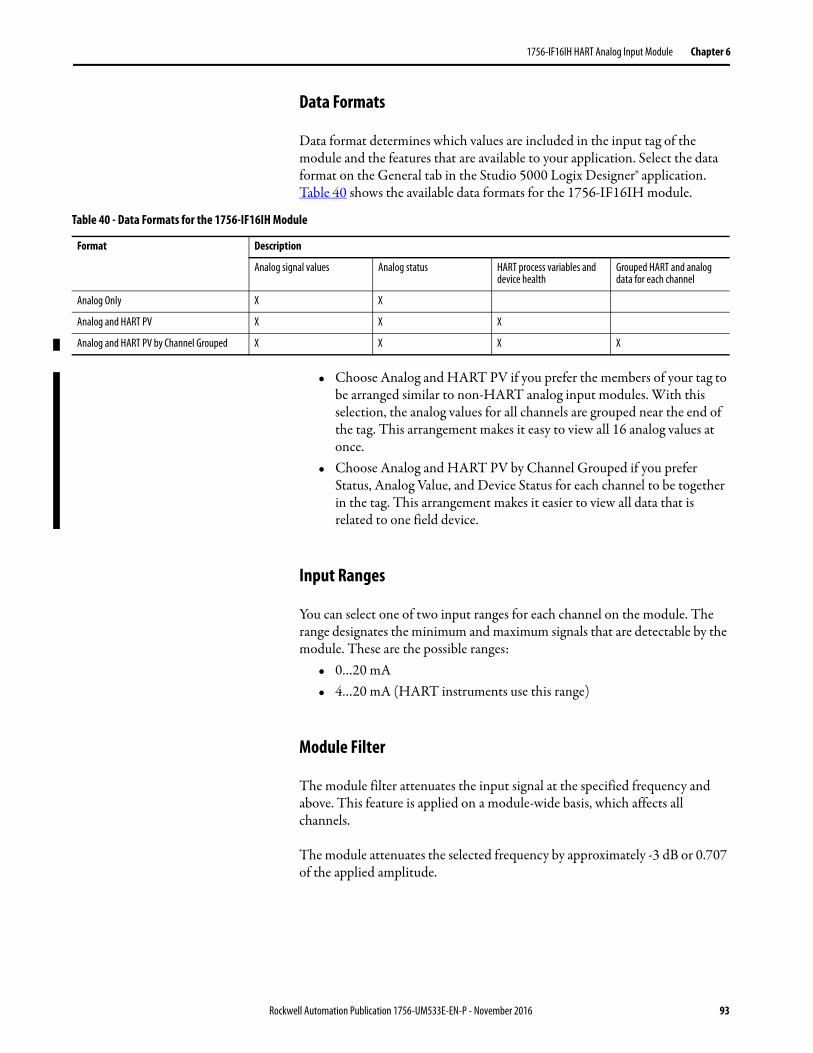
1756-IF16IH HART Analog Input Module Chapter 6
Data Formats
Data format determines which values are included in the input tag of the module and the features that are available to your application. Select the data format on the General tab in the Studio 5000 Logix Designer® application. Table 40 shows the available data formats for the 1756-IF16IH module.
• Choose Analog and HART PV if you prefer the members of your tag to be arranged similar to non-HART analog input modules. With this selection, the analog values for all channels are grouped near the end of the tag. This arrangement makes it easy to view all 16 analog values at once.
• Choose Analog and HART PV by Channel Grouped if you prefer Status, Analog Value, and Device Status for each channel to be together in the tag. This arrangement makes it easier to view all data that is related to one field device.
Input Ranges
You can select one of two input ranges for each channel on the module. The range designates the minimum and maximum signals that are detectable by the module. These are the possible ranges:
• 0…20 mA• 4…20 mA (HART instruments use this range)
Module Filter
The module filter attenuates the input signal at the specified frequency and above. This feature is applied on a module-wide basis, which affects all channels.
The module attenuates the selected frequency by approximately -3 dB or 0.707 of the applied amplitude.
Table 40 - Data Formats for the 1756-IF16IH Module
Format Description
Analog signal values Analog status HART process variables and device health
Grouped HART and analog data for each channel
Analog Only X X
Analog and HART PV X X X
Analog and HART PV by Channel Grouped X X X X
Rockwell Automation Publication 1756-UM533E-EN-P - November 2016 93
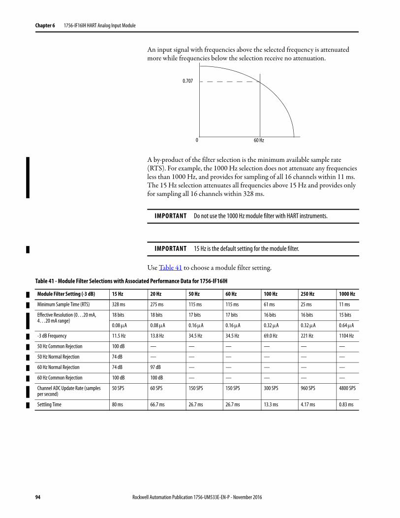
Chapter 6 1756-IF16IH HART Analog Input Module
An input signal with frequencies above the selected frequency is attenuated more while frequencies below the selection receive no attenuation.
A by-product of the filter selection is the minimum available sample rate (RTS). For example, the 1000 Hz selection does not attenuate any frequencies less than 1000 Hz, and provides for sampling of all 16 channels within 11 ms. The 15 Hz selection attenuates all frequencies above 15 Hz and provides only for sampling all 16 channels within 328 ms.
Use Table 41 to choose a module filter setting.
IMPORTANT Do not use the 1000 Hz module filter with HART instruments.
IMPORTANT 15 Hz is the default setting for the module filter.
0.707
60 Hz0
Table 41 - Module Filter Selections with Associated Performance Data for 1756-IF16IH
Module Filter Setting (-3 dB) 15 Hz 20 Hz 50 Hz 60 Hz 100 Hz 250 Hz 1000 Hz
Minimum Sample Time (RTS) 328 ms 275 ms 115 ms 115 ms 61 ms 25 ms 11 ms
Effective Resolution (0…20 mA, 4…20 mA range)
18 bits 18 bits 17 bits 17 bits 16 bits 16 bits 15 bits
0.08 A 0.08 A 0.16 A 0.16 A 0.32 A 0.32 A 0.64 A
-3 dB Frequency 11.5 Hz 13.8 Hz 34.5 Hz 34.5 Hz 69.0 Hz 221 Hz 1104 Hz
50 Hz Common Rejection 100 dB — — — — — —
50 Hz Normal Rejection 74 dB — — — — — —
60 Hz Normal Rejection 74 dB 97 dB — — — — —
60 Hz Common Rejection 100 dB 100 dB — — — — —
Channel ADC Update Rate (samples per second)
50 SPS 60 SPS 150 SPS 150 SPS 300 SPS 960 SPS 4800 SPS
Settling Time 80 ms 66.7 ms 26.7 ms 26.7 ms 13.3 ms 4.17 ms 0.83 ms
94 Rockwell Automation Publication 1756-UM533E-EN-P - November 2016
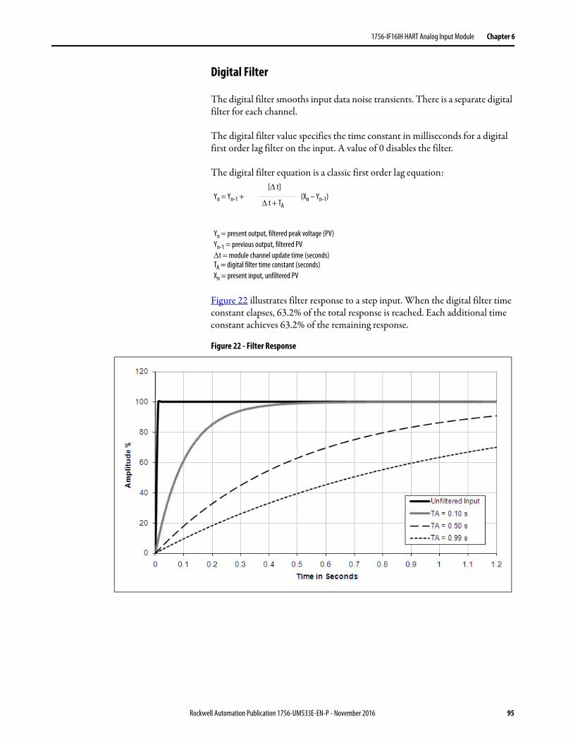
1756-IF16IH HART Analog Input Module Chapter 6
Digital Filter
The digital filter smooths input data noise transients. There is a separate digital filter for each channel.
The digital filter value specifies the time constant in milliseconds for a digital first order lag filter on the input. A value of 0 disables the filter.
The digital filter equation is a classic first order lag equation:
Figure 22 illustrates filter response to a step input. When the digital filter time constant elapses, 63.2% of the total response is reached. Each additional time constant achieves 63.2% of the remaining response.
Figure 22 - Filter Response
Yn = Yn-1 + (Xn – Yn-1)[ t]
t + TA
Yn = present output, filtered peak voltage (PV)Yn-1 = previous output, filtered PVt = module channel update time (seconds)TA = digital filter time constant (seconds)Xn = present input, unfiltered PV
Rockwell Automation Publication 1756-UM533E-EN-P - November 2016 95
Chapter 6 1756-IF16IH HART Analog Input Module
Real-time Sampling
This parameter instructs the module how often to scan its input channels and obtain new sampled data. After the channels are scanned, the module broadcasts that data (multicast or unicast) to the local chassis backplane. After the channels are scanned, the module multicasts that data. This feature is applied on a module-wide basis.
During module configuration, you specify a real-time sampling (RTS) period and a requested packet interval (RPI) period. Both of these features instruct the module to broadcast data, but only the RTS feature instructs the module to scan its channels before broadcasting.
For more RTS information, see Real Time Sample (RTS) on page 23.
Underrange and Overrange DetectionThe module detects when it is operating beyond limits of the input range. This status indication tells you that the input signal is not being measured accurately because the signal is beyond the measuring capability of the module. For example, the module cannot distinguish between 20.58...30 mA.
Table 42 shows the input ranges of the 1756-IF16IH module and the lowest and highest signal available in each range before the module detects an underrange and overrange condition.
Open Circuit Detection
In the 4...20 mA range, if the signal wire to a channel opens, the module reports a negative full-scale value in the input data tag of the channel within 5 seconds. The module also sets the ChxBrokenWire status bit.
In the 0...20 mA range, an open-circuit condition results in a measured value of 0 mA, which is the same as a measured value of 0 mA when there is not an open-circuit condition. The appropriate Underrange bit is set but the ChxBrokenWire bit is not set.
Table 42 - Low and High Signal Limits on the 1756-IF16IH Module
Input Module Available Range Lowest Signal in Range Highest Signal in Range
1756-IF16IH 0…20 mA 0 mA 20.58 mA
4…20 mA 3.42 mA 20.58 mA
96 Rockwell Automation Publication 1756-UM533E-EN-P - November 2016
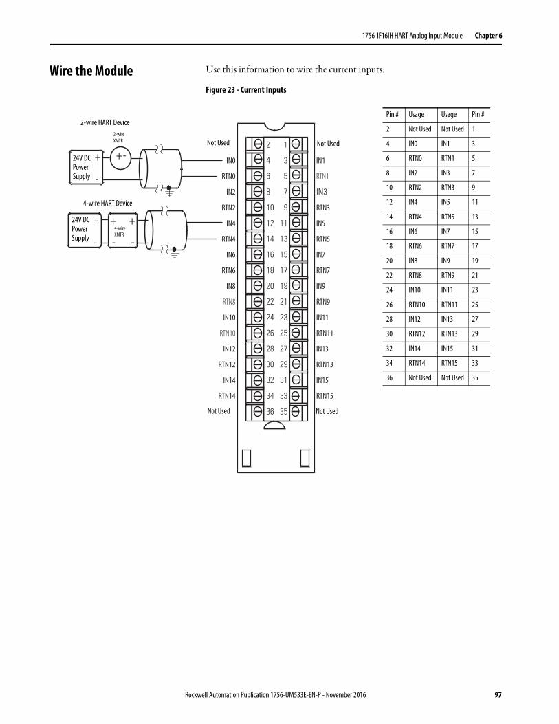
1756-IF16IH HART Analog Input Module Chapter 6
Wire the Module Use this information to wire the current inputs.
Figure 23 - Current Inputs
+
-
+
-
+
- -
+ - IN0
RTN0
IN2
RTN2
IN4
RTN4
IN6
RTN6
IN8
RTN8
IN10
RTN10
IN12
RTN12
IN14
RTN14
IN1
RTN1
IN3
RTN3
IN5
RTN5
IN7
RTN7
IN9
RTN9
IN11
RTN11
IN13
RTN13
IN15
RTN15
2
4
6
8
10
12
14
16
18
20
22
24
26
28
30
32
34
36
1
3
5
7
9
11
13
15
17
19
21
23
25
27
29
31
33
35
+
Pin # Usage Usage Pin #
2 Not Used Not Used 1
4 IN0 IN1 3
6 RTN0 RTN1 5
8 IN2 IN3 7
10 RTN2 RTN3 9
12 IN4 IN5 11
14 RTN4 RTN5 13
16 IN6 IN7 15
18 RTN6 RTN7 17
20 IN8 IN9 19
22 RTN8 RTN9 21
24 IN10 IN11 23
26 RTN10 RTN11 25
28 IN12 IN13 27
30 RTN12 RTN13 29
32 IN14 IN15 31
34 RTN14 RTN15 33
36 Not Used Not Used 35
4-wire XMTR
2-wire XMTR
2-wire HART Device
4-wire HART Device
24V DC Power Supply
24V DC Power Supply
Not Used
Not Used Not Used
Not Used
Rockwell Automation Publication 1756-UM533E-EN-P - November 2016 97
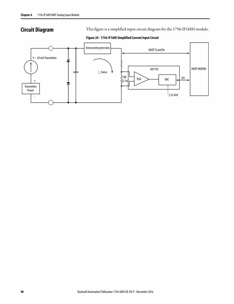
Chapter 6 1756-IF16IH HART Analog Input Module
Circuit Diagram This figure is a simplified input circuit diagram for the 1756-IF16IH module.
Figure 24 - 1756-IF16IH Simplified Current Input Circuit
Overcurrent protectionHART Tx and Rx
Transmitter Power
4 ~ 20 mA Transmitter
I_Sense
PGA
AD1792
+
-
ADC
HART MODEM
SPI
2.5v Vref
1000.1%
98 Rockwell Automation Publication 1756-UM533E-EN-P - November 2016
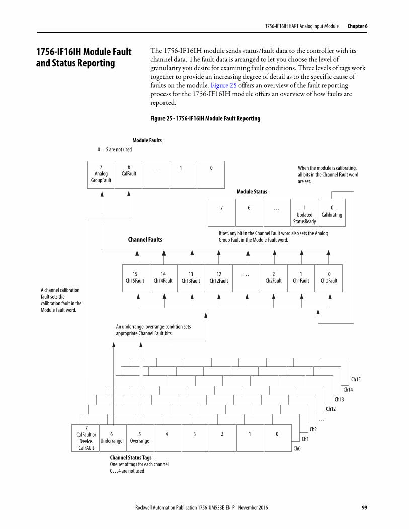
1756-IF16IH HART Analog Input Module Chapter 6
1756-IF16IH Module Fault and Status Reporting
The 1756-IF16IH module sends status/fault data to the controller with its channel data. The fault data is arranged to let you choose the level of granularity you desire for examining fault conditions. Three levels of tags work together to provide an increasing degree of detail as to the specific cause of faults on the module. Figure 25 offers an overview of the fault reporting process for the 1756-IF16IH module offers an overview of how faults are reported.
Figure 25 - 1756-IF16IH Module Fault Reporting
If set, any bit in the Channel Fault word also sets the Analog Group Fault in the Module Fault word.
A channel calibration fault sets the calibration fault in the Module Fault word.
An underrange, overrange condition sets appropriate Channel Fault bits.
When the module is calibrating, all bits in the Channel Fault word are set.
Module Faults
Channel Faults
Channel Status TagsOne set of tags for each channel0…4 are not used
7Analog
GroupFault
…
0…5 are not used
15Ch15Fault
14Ch14Fault
13Ch13Fault
12Ch12Fault
… 2Ch2Fault
1Ch1Fault
0Ch0Fault
7CalFault or
Device. CalFAUlt
6Underrange
5Overrange
4 3 2 1 0
Ch0
Ch1
Ch2
…
Ch12
Ch13
Ch14
Ch15
06CalFault
1
Module Status
7 6 … 1 Updated
StatusReady
0 Calibrating
Rockwell Automation Publication 1756-UM533E-EN-P - November 2016 99
Chapter 6 1756-IF16IH HART Analog Input Module
Table 43 shows the tags that can be examined in ladder logic to indicate when a fault has occurred.
1756-IF16IH Module Fault Word Bits
Bits in this word provide the highest level of fault detection. A nonzero condition in this word reveals that a fault exists on the module. You can examine further to isolate the fault. Table 44 lists tags that can be examined in ladder logic to indicate when a fault has occurred.
1756-IF16IH Channel Fault Tags
During normal module operation, bits in the Channel Fault word are set if any of the respective channels has an Under or Overrange condition. Checking this word for a nonzero value is a quick way to check for Under or Overrange conditions on the module.
Table 43 - 1756-IF16IH Tags That Can Be Examined in Ladder Logic
Tag Description Tag NameAnalog and HART PV
Tag NameAnalog and HART PV by Channel Grouped
Module Fault Word This word provides fault summary reporting. ModuleFaults ModuleFaults
Channel Fault Word This word provides clamp and communication fault reporting. ChannelFaultsChxxFault
ChannelFaultsChxxFault
Channel Status Tags These words provide individual channel limit, hold, open wire, ramp status, and calibration faults.
ChxxStatus Chxx.Device StatusChxx.DeviceStatus.AlarmStatus
HART Faults This provides HART communication status. HARTFaults, ChxxHARTFault Chxx.DeviceStatus.HARTFault
HART Device Status This provides HART field device health. HART.ChxxDevice Status Chxx.DeviceStatus.FieldDeviceStatus
Table 44 - 1756-IF16IH Tags That Can Be Examined in Ladder Logic
Tag Description
Analog Group Fault This bit is set when any bits in the Channel Fault word are set. Its tag name is AnalogGroupFault.
Calibration Fault This bit is set when any of the individual Channel Calibration Fault bits are set. Its tag name is CalFault.
Table 45 - 1756-IF16IH Conditions That Set All Channel Fault Word Bits
This Condition Sets All Channel Fault Word Bits And Causes the Module to Display the Following in the Channel Fault Word Bits
A channel is being calibrated 16#00FF
A communication fault occurred between the module and its owner-controller 16#FFFF
100 Rockwell Automation Publication 1756-UM533E-EN-P - November 2016
1756-IF16IH HART Analog Input Module Chapter 6
1756-IF16IH Channel Status Tags
Table 46 describes the channel status tags.
Module Calibration You can initiate calibration of the 1756-IF16IH module via the Logix Designer application Calibration tab.
The Calibration tab in the Logix Designer application provides a button to initiate module calibration and a display of the results. See Calibration Tab on page 170 for more information.
Module-defined Data Types, 1756-IF16IH Module
Table 47…Table 51 describe module-defined data types for the 1756-IF16IH module and include information for configuration and input tags.
Available tags depend on the selected input data format, as shown in Table 47.
Table 46 - 1756-IF16IH Tags That Show Channel Status(1)
Tag Bit Description
ChxCalFault 7 This bit is set if an error occurs during calibration for Channel x, which causes a bad calibration. Also sets CalFault in the Module Faults.
ChxUnderrange 6 This bit is set when the analog signal is less than or equal to the minimum detectable signal. Because the signal cannot be measured, it can be significantly below the minimum value. Also sets ChxxFault in the Channel Faults.
ChxOverrange 5 This bit is set when the analog signal is greater than or equal to the maximum detectable signal. Because the signal cannot be measured, it can be significantly above the maximum value. Also sets ChxxFault in the Channel Faults.
(1) Bits 0…4 are not used.
Table 47 - 1756-IF16IH Input Data Choice and Tags
Input Data Choice Tag Main Module Defined Type Subtype Used by Main Type
Analog Only Configuration AB:1756_IF16IH:C:0 AB:1756_IF16IH_ChConfig_Struct:C:0
Input AB:1756_IF16IH_Analog:I:0 None
Analog and HART PV Configuration AB:1756_IF16IH:C:0 AB:1756_IF16IH_ChConfig_Struct:C:0
Input AB:1756_IF16IH_HARTPV:I:1 AB:1756_IF16IH_HARTData:I:1AB:1756_IF16IH_HARTStatus_Struct:I:1
Analog and HART PV by ChannelGrouped
Configuration AB:1756_IF16IH:C:0 AB:1756_IF16IH_ChConfig_Struct:C:0
Input AB:1756_IF16IH_AnalogHARTbyChannel:I:0 AB:1756_IF16IH_HARTDataAll_1_Struct:I:0AB:1756_IF16IH_HARTStatusAll_1_Struct:I:0
Rockwell Automation Publication 1756-UM533E-EN-P - November 2016 101
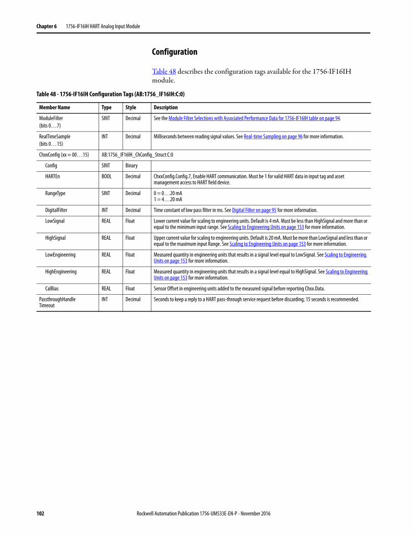
Chapter 6 1756-IF16IH HART Analog Input Module
Configuration
Table 48 describes the configuration tags available for the 1756-IF16IH module.
Table 48 - 1756-IF16IH Configuration Tags (AB:1756_IF16IH:C:0)
Member Name Type Style Description
ModuleFilter(bits 0…7)
SINT Decimal See the Module Filter Selections with Associated Performance Data for 1756-IF16IH table on page 94.
RealTimeSample(bits 0…15)
INT Decimal Milliseconds between reading signal values. See Real-time Sampling on page 96 for more information.
ChxxConfig (xx = 00…15) AB:1756_IF16IH_ChConfig_Struct:C:0
Config SINT Binary
HARTEn BOOL Decimal ChxxConfig.Config.7, Enable HART communication. Must be 1 for valid HART data in input tag and asset management access to HART field device.
RangeType SINT Decimal 0 = 0…20 mA1 = 4…20 mA
DigitalFilter INT Decimal Time constant of low pass filter in ms. See Digital Filter on page 95 for more information.
LowSignal REAL Float Lower current value for scaling to engineering units. Default is 4 mA. Must be less than HighSignal and more than or equal to the minimum input range. See Scaling to Engineering Units on page 153 for more information.
HighSignal REAL Float Upper current value for scaling to engineering units. Default is 20 mA. Must be more than LowSignal and less than or equal to the maximum input Range. See Scaling to Engineering Units on page 153 for more information.
LowEngineering REAL Float Measured quantity in engineering units that results in a signal level equal to LowSignal. See Scaling to Engineering Units on page 153 for more information.
HighEngineering REAL Float Measured quantity in engineering units that results in a signal level equal to HighSignal. See Scaling to Engineering Units on page 153 for more information.
CalBias REAL Float Sensor Offset in engineering units added to the measured signal before reporting Chxx.Data.
PassthroughHandleTimeout
INT Decimal Seconds to keep a reply to a HART pass-through service request before discarding; 15 seconds is recommended.
102 Rockwell Automation Publication 1756-UM533E-EN-P - November 2016
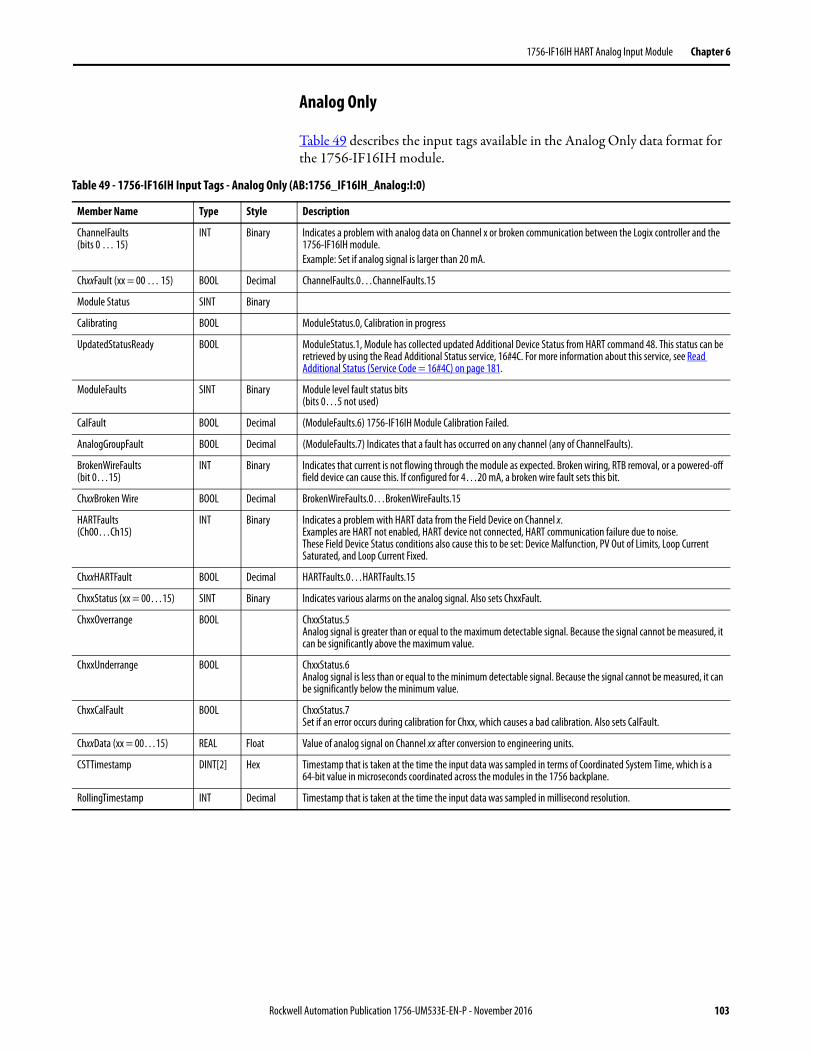
1756-IF16IH HART Analog Input Module Chapter 6
Analog Only
Table 49 describes the input tags available in the Analog Only data format for the 1756-IF16IH module.
Table 49 - 1756-IF16IH Input Tags - Analog Only (AB:1756_IF16IH_Analog:I:0)
Member Name Type Style Description
ChannelFaults(bits 0 … 15)
INT Binary Indicates a problem with analog data on Channel x or broken communication between the Logix controller and the 1756-IF16IH module.Example: Set if analog signal is larger than 20 mA.
ChxxFault (xx = 00 … 15) BOOL Decimal ChannelFaults.0…ChannelFaults.15
Module Status SINT Binary
Calibrating BOOL ModuleStatus.0, Calibration in progress
UpdatedStatusReady BOOL ModuleStatus.1, Module has collected updated Additional Device Status from HART command 48. This status can be retrieved by using the Read Additional Status service, 16#4C. For more information about this service, see Read Additional Status (Service Code = 16#4C) on page 181.
ModuleFaults SINT Binary Module level fault status bits (bits 0…5 not used)
CalFault BOOL Decimal (ModuleFaults.6) 1756-IF16IH Module Calibration Failed.
AnalogGroupFault BOOL Decimal (ModuleFaults.7) Indicates that a fault has occurred on any channel (any of ChannelFaults).
BrokenWireFaults(bit 0…15)
INT Binary Indicates that current is not flowing through the module as expected. Broken wiring, RTB removal, or a powered-off field device can cause this. If configured for 4…20 mA, a broken wire fault sets this bit.
ChxxBroken Wire BOOL Decimal BrokenWireFaults.0…BrokenWireFaults.15
HARTFaults(Ch00…Ch15)
INT Binary Indicates a problem with HART data from the Field Device on Channel x. Examples are HART not enabled, HART device not connected, HART communication failure due to noise.These Field Device Status conditions also cause this to be set: Device Malfunction, PV Out of Limits, Loop Current Saturated, and Loop Current Fixed.
ChxxHARTFault BOOL Decimal HARTFaults.0…HARTFaults.15
ChxxStatus (xx = 00…15) SINT Binary Indicates various alarms on the analog signal. Also sets ChxxFault.
ChxxOverrange BOOL ChxxStatus.5 Analog signal is greater than or equal to the maximum detectable signal. Because the signal cannot be measured, it can be significantly above the maximum value.
ChxxUnderrange BOOL ChxxStatus.6 Analog signal is less than or equal to the minimum detectable signal. Because the signal cannot be measured, it can be significantly below the minimum value.
ChxxCalFault BOOL ChxxStatus.7 Set if an error occurs during calibration for Chxx, which causes a bad calibration. Also sets CalFault.
ChxxData (xx = 00…15) REAL Float Value of analog signal on Channel xx after conversion to engineering units.
CSTTimestamp DINT[2] Hex Timestamp that is taken at the time the input data was sampled in terms of Coordinated System Time, which is a 64-bit value in microseconds coordinated across the modules in the 1756 backplane.
RollingTimestamp INT Decimal Timestamp that is taken at the time the input data was sampled in millisecond resolution.
Rockwell Automation Publication 1756-UM533E-EN-P - November 2016 103
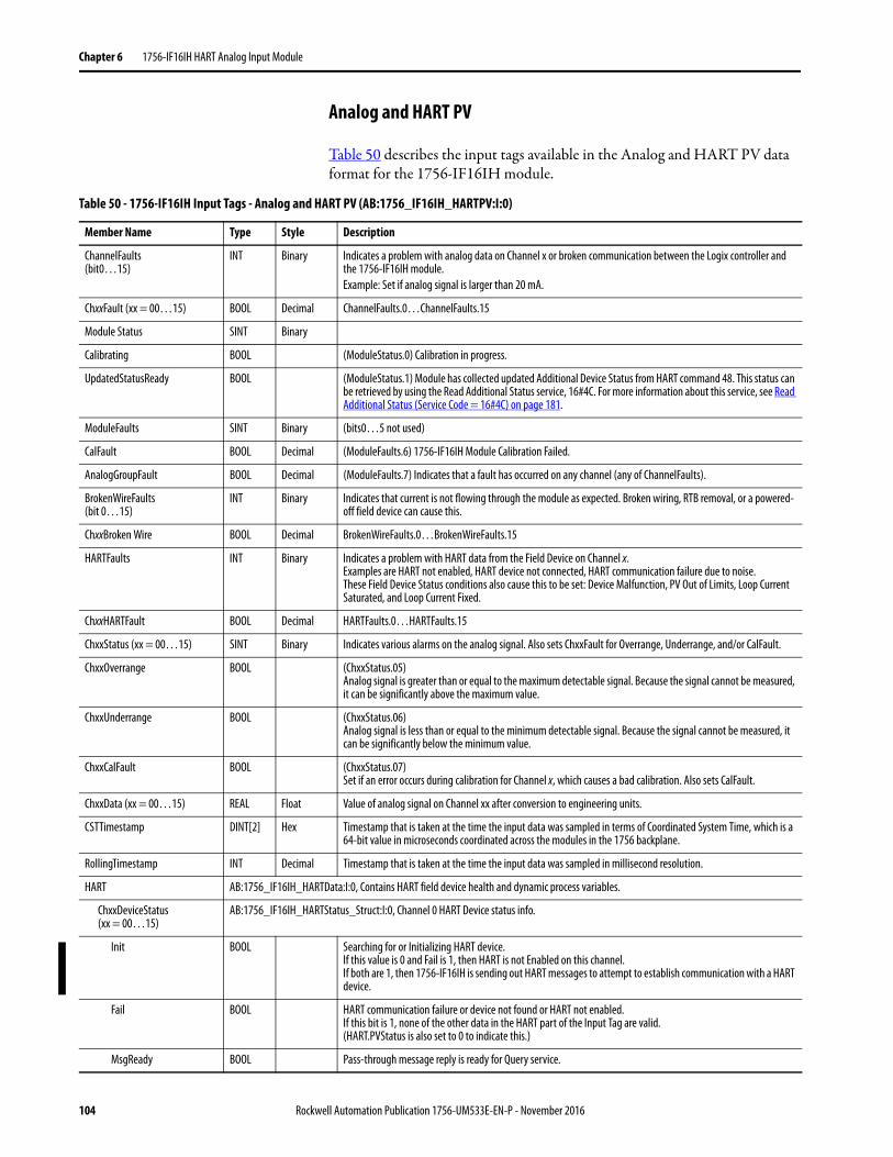
Chapter 6 1756-IF16IH HART Analog Input Module
Analog and HART PV
Table 50 describes the input tags available in the Analog and HART PV data format for the 1756-IF16IH module.
Table 50 - 1756-IF16IH Input Tags - Analog and HART PV (AB:1756_IF16IH_HARTPV:I:0)
Member Name Type Style Description
ChannelFaults(bit0…15)
INT Binary Indicates a problem with analog data on Channel x or broken communication between the Logix controller and the 1756-IF16IH module.Example: Set if analog signal is larger than 20 mA.
ChxxFault (xx = 00…15) BOOL Decimal ChannelFaults.0…ChannelFaults.15
Module Status SINT Binary
Calibrating BOOL (ModuleStatus.0) Calibration in progress.
UpdatedStatusReady BOOL (ModuleStatus.1) Module has collected updated Additional Device Status from HART command 48. This status can be retrieved by using the Read Additional Status service, 16#4C. For more information about this service, see Read Additional Status (Service Code = 16#4C) on page 181.
ModuleFaults SINT Binary (bits0…5 not used)
CalFault BOOL Decimal (ModuleFaults.6) 1756-IF16IH Module Calibration Failed.
AnalogGroupFault BOOL Decimal (ModuleFaults.7) Indicates that a fault has occurred on any channel (any of ChannelFaults).
BrokenWireFaults(bit 0…15)
INT Binary Indicates that current is not flowing through the module as expected. Broken wiring, RTB removal, or a powered-off field device can cause this.
ChxxBroken Wire BOOL Decimal BrokenWireFaults.0…BrokenWireFaults.15
HARTFaults INT Binary Indicates a problem with HART data from the Field Device on Channel x. Examples are HART not enabled, HART device not connected, HART communication failure due to noise.These Field Device Status conditions also cause this to be set: Device Malfunction, PV Out of Limits, Loop Current Saturated, and Loop Current Fixed.
ChxxHARTFault BOOL Decimal HARTFaults.0…HARTFaults.15
ChxxStatus (xx = 00…15) SINT Binary Indicates various alarms on the analog signal. Also sets ChxxFault for Overrange, Underrange, and/or CalFault.
ChxxOverrange BOOL (ChxxStatus.05) Analog signal is greater than or equal to the maximum detectable signal. Because the signal cannot be measured, it can be significantly above the maximum value.
ChxxUnderrange BOOL (ChxxStatus.06) Analog signal is less than or equal to the minimum detectable signal. Because the signal cannot be measured, it can be significantly below the minimum value.
ChxxCalFault BOOL (ChxxStatus.07)Set if an error occurs during calibration for Channel x, which causes a bad calibration. Also sets CalFault.
ChxxData (xx = 00…15) REAL Float Value of analog signal on Channel xx after conversion to engineering units.
CSTTimestamp DINT[2] Hex Timestamp that is taken at the time the input data was sampled in terms of Coordinated System Time, which is a 64-bit value in microseconds coordinated across the modules in the 1756 backplane.
RollingTimestamp INT Decimal Timestamp that is taken at the time the input data was sampled in millisecond resolution.
HART AB:1756_IF16IH_HARTData:I:0, Contains HART field device health and dynamic process variables.
ChxxDeviceStatus (xx = 00…15)
AB:1756_IF16IH_HARTStatus_Struct:I:0, Channel 0 HART Device status info.
Init BOOL Searching for or Initializing HART device. If this value is 0 and Fail is 1, then HART is not Enabled on this channel. If both are 1, then 1756-IF16IH is sending out HART messages to attempt to establish communication with a HART device.
Fail BOOL HART communication failure or device not found or HART not enabled. If this bit is 1, none of the other data in the HART part of the Input Tag are valid. (HART.PVStatus is also set to 0 to indicate this.)
MsgReady BOOL Pass-through message reply is ready for Query service.
104 Rockwell Automation Publication 1756-UM533E-EN-P - November 2016
1756-IF16IH HART Analog Input Module Chapter 6
Analog and HART PV by Channel Grouped
Table 51 describes the input tags available in the Analog and HART PV by Channel Grouped data format for the 1756-IF16IH module.
CurrentFault BOOL Analog current measurement does not match the current the Field Device reported over HART network.
ConfigurationChanged BOOL The Field Device configuration has changed and new Field Device configuration information can be obtained from the 1756-IF16IH module via CIP MSG GetDeviceInfo, which clears this bit.
ResponseCode SINT Binary HART communication status byte or Response code from a recent HART reply. See Response Code and Field Device Status on page 229 for more information.
FieldDeviceStatus SINT Binary HART device status byte from a recent HART reply. Indicates the health of the HART Field device. See Field Device Status Bit Mask Definitions on page 230 for more information.
ExtDeviceStatus SINT Binary Extended device status byte.Bit 0 is Maintenance Needed.Bit 1 is Device Variable Alert.Bit 2 is Low Power.
ChxxPV (xx = 00…15) REAL Channel xx HART PV Value.
ChxxSV (xx = 00…15) REAL Channel xx HART SV Value.
ChxxTV (xx = 00…15) REAL Channel xx HART TV Value.
ChxxFV (xx = 00…15) REAL Channel xx HART FV Value.
ChxxPVStatus (xx = 00…15)
SINT Channel xx HART PV Status. See HART PV, SV, TV, and FV Status on page 236 for more information.
ChxxSVStatus(xx = 00…15)
SINT Channel xx HART SV Status. See HART PV, SV, TV, and FV Status on page 236 for more information.
ChxxTVStatus(xx = 00…15)
SINT Channel xx HART TV Status. See HART PV, SV, TV, and FV Status on page 236 for more information.
ChxxFVStatus(xx = 00…15)
SINT Channel xx HART FV Status. See HART PV, SV, TV, and FV Status on page 236 for more information.
Table 50 - 1756-IF16IH Input Tags - Analog and HART PV (AB:1756_IF16IH_HARTPV:I:0)
Member Name Type Style Description
Table 51 - 1756-IF16IH Input Tags - Analog and HART PV by Channel Grouped (AB:1756-IF16IH_AnalogHARTbyChannel:I:0)
Member Name Type Style Description
ChannelFaults INT Binary Indicates a problem with analog data on Channel xx or broken communication between the Logix controller and the 1756-IF16IH module.Example: Set if analog signal is larger than 20 mA.
ChxxFault (xx = 00…15) BOOL ChannelFaults.xx
ModuleStatus SINT Binary
Calibrating BOOL Decimal (ModuleStatus.0) Calibration in progress.
UpdatedStatusReady BOOL Decimal (ModuleStatus.1) Module has collected updated Additional Device Status from HART command 48. This status can be retrieved by using the Read Additional Status service, 16#4C. For more information about this service, see Read Additional Status (Service Code = 16#4C) on page 181.
ModuleFaults SINT Binary
CalFault BOOL (ModuleFaults.6) 1756-IF16IH module calibration failed.
AnalogGroupFault BOOL Decimal (ModuleFaults.7) Indicates that a fault has occurred on any channel (any of ChannelFaults).
Chxx (xx = 00…15) AB:1756_IF16IH_HARTDataAll_Struct:I:0, Channel xx analog and HART data.
Data REAL Float Analog value in engineering units.
Rockwell Automation Publication 1756-UM533E-EN-P - November 2016 105
Chapter 6 1756-IF16IH HART Analog Input Module
DeviceStatus AB:1756_IF16IH_HARTStatusAll_Struct:I:0, Channel 00 HART Device status info.
HARTInit BOOL Decimal Searching for or Initializing HART device. If this value is 0 and Fail is 1, then HART is not Enabled on this channel. If both are 1, then 1756-IF16IH is sending out HART messages to attempt to establish communication with a HART device.
HARTCommFail BOOL Decimal HART communication failure or device not found or HART not enabled. If this bit is 1, none of the other data in the HART part of the Input Tag are valid. (HART.PVStatus is also set to 0 to indicate this.)
MsgReady BOOL Decimal Pass-through message reply is ready for query service.
CurrentFault BOOL Decimal Analog current measurement does not match the current the Field Device reported over the HART network.
ConfigurationChanged BOOL Decimal The field device configuration has changed and new field device configuration information can be obtained from the 1756-IF16IH module via CIP MSG GetDeviceInfo, which clears this bit.
MaintenanceRequired BOOL Bit 0 of Extended Device Status (if using CMD 9, or from CMD 48 if supported).
BrokenWire BOOL Decimal Indicates that current is not flowing through the module as expected. Broken wiring, RTB removal, or a powered-off field device can cause this.
HARTFault BOOL Decimal Indicates a problem with HART data from the field device on Channel xx. Examples are HART not enabled, HART device not connected, HART communication failuredue to noise.These Field Device Status conditions also cause this to be set: Device Malfunction,PV Out of Limits, Loop Current Saturated, and Loop Current Fixed.
ResponseCode SINT Binary HART communication status byte or Response code from a recent HART reply. See Response Code and Field Device Status on page 229 for more information.
FieldDeviceStatus SINT Binary HART device status byte from a recent HART reply. Indicates the health of the HART Field device. See Field Device Status Bit Mask Definitions on page 230 for more information.
AlarmStatus SINT Binary Indicates various alarms on the analog signal.
DeviceVariableAlert BOOL AlarmStatus.4, Bit 1 of Extended Device Status. Device reports a problem with some measurement.
Overrange BOOL AlarmStatus.5, Signal value over range (over 20 mA).
Underrange BOOL AlarmStatus.6, Signal value under range.(less than 3.4 mA if configured for 4…20 mA).
CalFault BOOL AlarmStatus.7, Bad calibration.
PV REAL Float Primary value. This is the same value as signaled on the analog channel and is the most important measurement that is made by this device.
SV REAL Float Secondary value
TV REAL Float Third value
FV REAL Float Fourth value
PVStatus SINT Hex Primary status16#C0 = Connected16#00 = Not Connected
SVStatus SINT Hex Secondary status16#C0 = Connected16#00 = Not Connected
TVStatus SINT Hex Third status16#C0 = Connected16#00 = Not Connected
FVStatus SINT Hex Fourth status16#C0 = Connected16#00 = Not Connected
CSTTimestamp DINT[2] Hex Timestamp that is taken at the time the input data was sampled in terms of coordinated system time, which is a 64-bit value in microseconds coordinated across the modules in the 1756 backplane.
RollingTimestamp INT Decimal Timestamp that is taken at the time the input data was sampled in millisecond resolution.
Table 51 - 1756-IF16IH Input Tags - Analog and HART PV by Channel Grouped (AB:1756-IF16IH_AnalogHARTbyChannel:I:0)
Member Name Type Style Description
106 Rockwell Automation Publication 1756-UM533E-EN-P - November 2016
Chapter 7
1756-OF8H HART Analog Output Module
This chapter discusses these topics.
Module Features The 1756-OF8H module has the following features:• Choice of three data formats
• Analog only• Analog and HART PV• Analog and HART by channel
• 15-bit or 16-bit resolution• Ramping and rate limiting• Hold for initialization• Open wire detection• Clamping and limited• Clamp and limit alarms• Data echo
Topic Page
Module Features 107
Wire the Module 111
Use Module Block and Output Circuit Diagrams 112
1756-OF8H Module Fault and Status Reporting 113
1756-OF8H Fault Reporting 114
Module-defined Data Types, 1756-OF8H Module 117
IMPORTANT The Analog and HART by Channel data type is available only for 1756-OF8H firmware revision 2.001
Rockwell Automation Publication 1756-UM533E-EN-P - November 2016 107
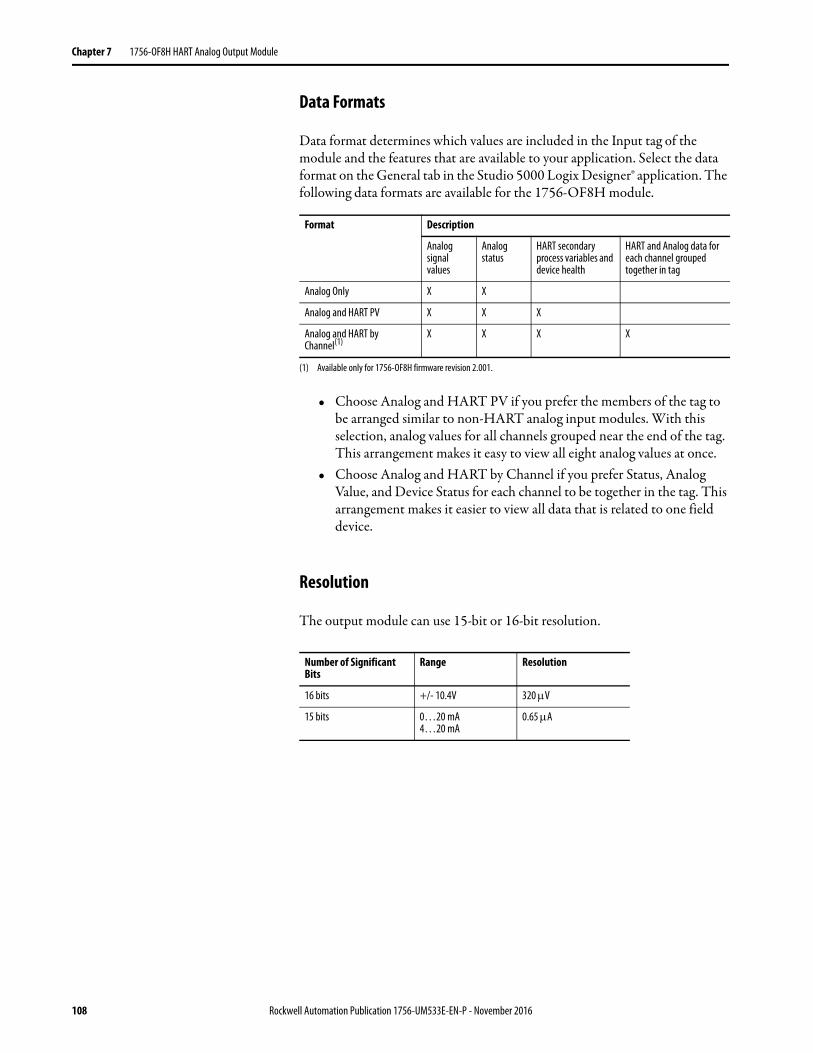
Chapter 7 1756-OF8H HART Analog Output Module
Data Formats
Data format determines which values are included in the Input tag of the module and the features that are available to your application. Select the data format on the General tab in the Studio 5000 Logix Designer® application. The following data formats are available for the 1756-OF8H module.
• Choose Analog and HART PV if you prefer the members of the tag to be arranged similar to non-HART analog input modules. With this selection, analog values for all channels grouped near the end of the tag. This arrangement makes it easy to view all eight analog values at once.
• Choose Analog and HART by Channel if you prefer Status, Analog Value, and Device Status for each channel to be together in the tag. This arrangement makes it easier to view all data that is related to one field device.
Resolution
The output module can use 15-bit or 16-bit resolution.
Format Description
Analog signal values
Analog status
HART secondary process variables and device health
HART and Analog data for each channel grouped together in tag
Analog Only X X
Analog and HART PV X X X
Analog and HART by Channel(1)
(1) Available only for 1756-OF8H firmware revision 2.001.
X X X X
Number of Significant Bits
Range Resolution
16 bits +/- 10.4V 320 V
15 bits 0…20 mA4…20 mA
0.65 A
108 Rockwell Automation Publication 1756-UM533E-EN-P - November 2016
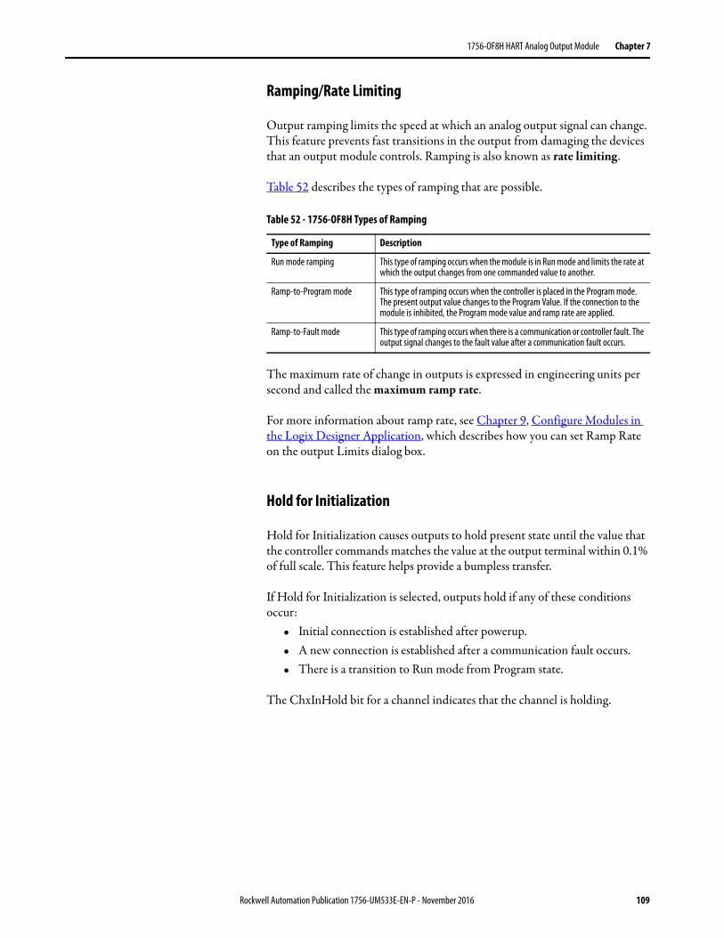
1756-OF8H HART Analog Output Module Chapter 7
Ramping/Rate Limiting
Output ramping limits the speed at which an analog output signal can change. This feature prevents fast transitions in the output from damaging the devices that an output module controls. Ramping is also known as rate limiting.
Table 52 describes the types of ramping that are possible.
The maximum rate of change in outputs is expressed in engineering units per second and called the maximum ramp rate.
For more information about ramp rate, see Chapter 9, Configure Modules in the Logix Designer Application, which describes how you can set Ramp Rate on the output Limits dialog box.
Hold for Initialization
Hold for Initialization causes outputs to hold present state until the value that the controller commands matches the value at the output terminal within 0.1% of full scale. This feature helps provide a bumpless transfer.
If Hold for Initialization is selected, outputs hold if any of these conditions occur:
• Initial connection is established after powerup.• A new connection is established after a communication fault occurs.• There is a transition to Run mode from Program state.
The ChxInHold bit for a channel indicates that the channel is holding.
Table 52 - 1756-OF8H Types of Ramping
Type of Ramping Description
Run mode ramping This type of ramping occurs when the module is in Run mode and limits the rate at which the output changes from one commanded value to another.
Ramp-to-Program mode This type of ramping occurs when the controller is placed in the Program mode. The present output value changes to the Program Value. If the connection to the module is inhibited, the Program mode value and ramp rate are applied.
Ramp-to-Fault mode This type of ramping occurs when there is a communication or controller fault. The output signal changes to the fault value after a communication fault occurs.
Rockwell Automation Publication 1756-UM533E-EN-P - November 2016 109
Chapter 7 1756-OF8H HART Analog Output Module
Open Wire Detection
This feature detects when current flow is not present at any channel. The1756-OF8H module must be configured for 0…20 mA or 4…20 mA operation to use this feature. At least 0.1 mA of current must be flowing from the output for detection to occur.
When an open wire condition occurs at any channel, a status bit named ChxOpenWire is set for that channel.
Clamping and Limiting
The clamping feature limits the output from the analog module to remain within a range that the controller configures, even when the controller commands an output outside that range. This safety feature sets a high clamp and a low clamp.
Once clamps are set for a channel, any data that is received from the controller that exceeds the clamps sets a limit alarm and transitions the output to that limit but not beyond the configured clamp value. For example, suppose that an application sets the high clamp on a module for 8V and the low clamp for -8V. If a controller sends a value that corresponds to 9V to the module, the module applies only 8V to its screw terminals. The signal value that is applied is reflected in the Input Tag ChxData field.
Clamping limits are entered in engineering units.
Clamp and Limit AlarmsThis function works directly with clamping. When a module receives a data value from the controller that exceeds clamping limits, it applies the clamping limit to the signal value and sends a status bit to the controller, notifying it that the commanded output data value exceeds the clamping limits.
For example, if a channel has clamping limits of 8V and -8V but receives data to apply 9V, the module applies 8V to the screw terminals and sends a status bit to the controller. This status bit informs the controller that the 9V value exceeds the channel clamping limits.
Clamping alarms can be disabled or latched on a per channel basis. Clamping limits are entered in engineering units.
110 Rockwell Automation Publication 1756-UM533E-EN-P - November 2016
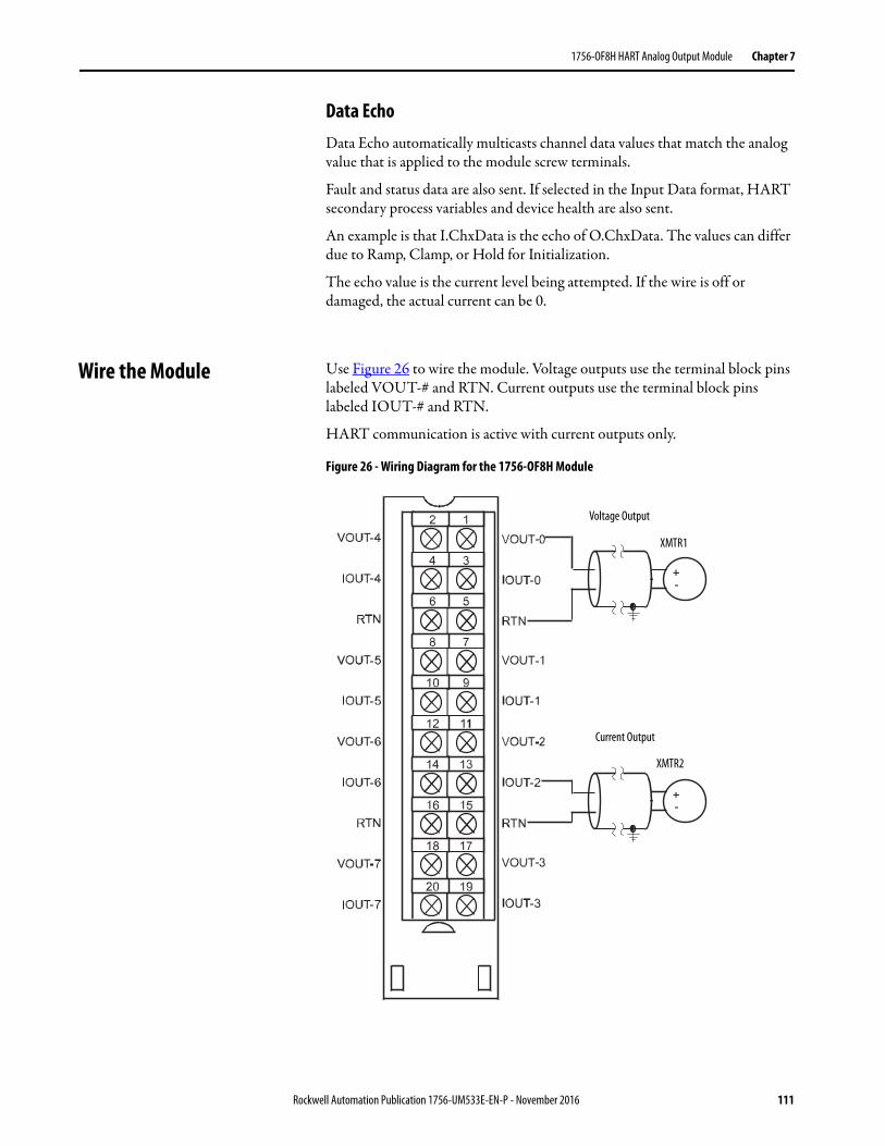
1756-OF8H HART Analog Output Module Chapter 7
Data EchoData Echo automatically multicasts channel data values that match the analog value that is applied to the module screw terminals.
Fault and status data are also sent. If selected in the Input Data format, HART secondary process variables and device health are also sent.
An example is that I.ChxData is the echo of O.ChxData. The values can differ due to Ramp, Clamp, or Hold for Initialization.
The echo value is the current level being attempted. If the wire is off or damaged, the actual current can be 0.
Wire the Module Use Figure 26 to wire the module. Voltage outputs use the terminal block pins labeled VOUT-# and RTN. Current outputs use the terminal block pins labeled IOUT-# and RTN.
HART communication is active with current outputs only.
Figure 26 - Wiring Diagram for the 1756-OF8H Module
Current Output
Voltage Output
XMTR1
XMTR2
Rockwell Automation Publication 1756-UM533E-EN-P - November 2016 111
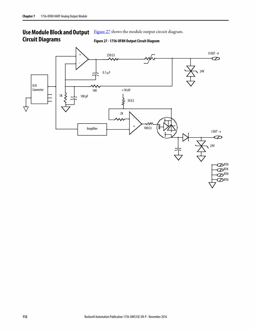
Chapter 7 1756-OF8H HART Analog Output Module
Use Module Block and Output Circuit Diagrams
Figure 27 shows the module output circuit diagram.
Figure 27 - 1756-OF8H Output Circuit Diagram
0.1 F
D/AConverter
250
Amplifier
100 pF5K50
16K
RTNRTNRTN
RTN
-
+
+18.6V
+
-
2K
24V
24V
I OUT - x
V OUT - #
100
112 Rockwell Automation Publication 1756-UM533E-EN-P - November 2016
1756-OF8H HART Analog Output Module Chapter 7
1756-OF8H Module Fault and Status Reporting
The 1756-OF8H modules multicast status and fault data to the controller with their channel data. The fault data is arranged to let you choose the level of granularity you desire for examining fault conditions.
Three levels of tags work together to provide increasing degree of detail as to the specific cause of faults on the module.
Table 53 lists tags that you can examine in ladder logic to indicate when a fault occurred.
Table 53 - 1756-OF8H Tags That Can Be Examined in Ladder Logic
Tag Description Tag NameAnalog and HART PV
Tag NameAnalog and HART by Channel(1)
Module Fault Word This word provides fault summary reporting. ModuleFaults ModuleFaults
Channel Fault Word This word provides clamp and communication fault reporting. ChannelFaultsChxFault
ChannelFaultsChxFault
Channel Status Tags These words, one per channel, provide individual channel limit, hold, open wire, ramp status, and calibration faults.
ChxStatus Chx.DeviceStatusChx.DeviceStatus.AlarmStatus
HART Faults This provides HART communication status. HARTFaults, ChxHARTFault Chx.DeviceStatus.HARTFault
HART Device Status This provides HART field device health. HART.ChxDevice Status Chx.DeviceStatus.FieldDeviceStatus
(1) Available only for 1756-OF8H firmware revision 2.001.
Rockwell Automation Publication 1756-UM533E-EN-P - November 2016 113
Chapter 7 1756-OF8H HART Analog Output Module
1756-OF8H Fault Reporting Figure 28 offers an overview of the fault reporting process.
Figure 28 - 1756-OF8H Module Fault Reporting
Module Faults
Channel Faults
Channel Status Tags
7Analog
GroupFault
6 5 4
6, 5, 4, and 0 are not used for fault reporting
Not a Number, Output in Hold, and Ramp Alarm conditions do not set additional bits. You must monitor them here.
If set, any bit in the Channel Fault word, also sets the Analog Group Fault in the Module Fault word.
A channel calibration fault sets the calibration fault in the Module Fault word.
When the module is calibrating, all bits in the Channel Fault word are set.
7Ch7Fault
41519
6Ch6Fault
5Ch5Fault
4Ch4Fault
3Ch3Fault
2Ch2Fault
1Ch1Fault
0Ch0Fault
7OpenWire
Bit 6 is not used
6 5NotA
Number
4CalFault
3InHold
2RampAlarm
1LLimitAlarm
0HLimitAlarm Ch0
Ch1
Ch2
Ch3
Ch4
Ch5
Ch6Ch7
2Calibrating
1CalFault
0
One set of tags for each channel
8LoopOutput
Fault
3Updated
StatusReady
114 Rockwell Automation Publication 1756-UM533E-EN-P - November 2016
1756-OF8H HART Analog Output Module Chapter 7
Module Fault Word Bits
Bits in this word provide the highest level of fault detection. A nonzero condition in this word reveals that a fault exists on the module. You can examine further down to isolate the fault.
Table 54 lists tags that are found in the Module Fault word.
Channel Fault Word Bits
During normal module operation, bits in the Channel Fault word are set if any of the respective channels has a High or Low Limit Alarm or an Open Wire condition (0…20 mA or 4…20 mA configurations only). When using the Channel Fault Word, the 1756-OF8H module uses bits 0…7. Checking this word for a nonzero condition is a quick way to check for these conditions on a channel.
Table 55 lists the conditions that set all Channel Fault word bits.
Your logic monitors the Channel Fault bit for a particular output under the following conditions:
• You enable output clamping• You are checking for an open wire condition (0…20 mA configuration
only)• You must know if the output module is not communicating with the
controller
Your logic can use the bit in Channel Faults, for example, Ch2Fault, to take failure recovery action, such as signaling CVFault on a PIDE function block.
Table 54 - 1756-OF8H Tags Found in the Module Fault Word
Tag Description Tag Name
Analog Group Fault This bit is set when any bits in the Channel Fault word are set.
AnalogGroupFault
Calibrating This bit is set when any channel is being calibrated. When this bit is set, all bits in the Channel Fault word are set.
Calibrating
Calibration Fault This bit is set when any of the individual Channel Calibration Fault bits are set.
CalFault
Table 55 - 1756-OF8H Conditions That Set All Channel Fault Word Bits
This Condition Sets All Channel Fault Word Bits
And Causes the Module to Display the Following in the Channel Fault Word Bits
A channel is being calibrated 16#00FF
A communication fault occurred between the module and its owner-controller
1#FFFF
Rockwell Automation Publication 1756-UM533E-EN-P - November 2016 115
Chapter 7 1756-OF8H HART Analog Output Module
Channel Status Tags
Any of the channel status words (eight words for 1756-OF8H modules), one for each channel, display a nonzero condition if that particular channel has faulted. Some of these bits set bits in other Fault words.
When the High or Low Limit Alarm bits (ChxHLimitAlarm or ChxLLimit Alarm) in any of the words are set, the appropriate bit is set in the Channel Fault word.
When the Calibration Fault bit (CalFault) is set in any of the words, the Calibration Fault bit (bit 11) is set in the Module Fault word. Table 56 lists the conditions that set each of the word bits.
Table 56 - 1756-OF8H Conditions That Set Each of the Word Bits(1)
Tag (status words) Bit Event That Sets This Tag
ChxOpenWireChx.DeviceStatus.OpenWire
7 This bit is set only if the configured Output Range is 0…20 or 4…20 mA. The circuit must also become open due to a wire falling off or being cut when the output being driven is above 0.1 mA. The bit remains set until correct wiring is restored.
ChxNotaNumber(2)
Chx.DeviceStatus.NotANumber5 This bit is set when the output value that is received from the controller is NotANumber (the IEEE NaN value). The output
channel holds its last state.
ChxCalFaultChx.DeviceStatus.CalFault
4 This bit is set when an error occurred when calibrating. This bit also sets the appropriate bit in the Channel Fault word.
ChxInHold(2)
Chx.DeviceStatus.InHold3 This bit is set when the output channel is holding. The bit resets when the requested Run mode output value is within
0.1% of full-scale of the current echo value.
ChxRampAlarm(2)
Chx.DeviceStatus.RampAlarm2 This bit is set when the requested rate of change of the output channel exceeds the configured maximum ramp rate
requested parameter. It remains set until the output reaches its target value and ramping stops. If the bit is latched, it remains set until it is unlatched.
ChxLLimitAlarmChx.DeviceStatus.LLimitAlarm
1 This bit is set when the requested output value is beneath the configured low limit value. It remains set until the requested output is above the low limit. If the bit is latched, it remains set until it is unlatched.
ChxHLimitAlarmChx.DeviceStatus.HLimitAlarm
0 This bit is set when the requested output value is above the configured high limit value. It remains set until the requested output is below the high limit. If the bit is latched, it remains set until it is unlatched.
(1) Bit 6 is not used.(2) This bit does not set additional bits at any higher level.
116 Rockwell Automation Publication 1756-UM533E-EN-P - November 2016
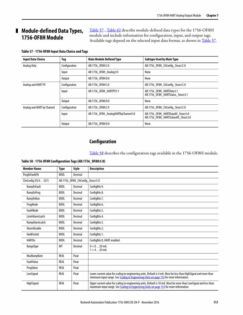
1756-OF8H HART Analog Output Module Chapter 7
Module-defined Data Types, 1756-OF8H Module
Table 57…Table 62 describe module-defined data types for the 1756-OF8H module and include information for configuration, input, and output tags.Available tags depend on the selected input data format, as shown in Table 57.
Configuration
Table 58 describes the configuration tags available in the 1756-OF8H module.
Table 57 - 1756-OF8H Input Data Choice and Tags
Input Data Choice Tag Main Module Defined Type Subtype Used by Main Type
Analog Only Configuration AB:1756_OF8H:C:0 AB:1756_OF8H_ChConfig_Struct:C:0
Input AB:1756_OF8H_Analog:I:0 None
Output AB:1756_OF8H:O:0 None
Analog and HART PV Configuration AB:1756_OF8H:C:0 AB:1756_OF8H_ChConfig_Struct:C:0
Input AB:1756_OF8H_HARTPV:I:1 AB:1756_OF8H_HARTData:I:1AB:1756_OF8H_HARTStatus_Struct:I:1
Output AB:1756_OF8H:O:0 None
Analog and HART by Channel Configuration AB:1756_OF8H:C:0 AB:1756_OF8H_ChConfig_Struct:C:0
Input AB:1756_OF8H_AnalogHARTbyChannel:I:0 AB:1756_OF8H_HARTDataAll_Struct:I:0AB:1756_OF8H_HARTStatusAll_Struct:I:0
Output AB:1756_OF8H:O:0 None
Table 58 - 1756-OF8H Configuration Tags (AB:1756_OF8H:C:0)
Member Name Type Style Description
ProgToFaultEN BOOL Decimal
ChxConfig (Ch 0…Ch7) AB:1756_OF8H_ChConfig_Struct:C:0
RampToFault BOOL Decimal ConfigBits:9.
RampToProg BOOL Decimal ConfigBits:8.
RampToRun BOOL Decimal ConfigBits:7.
ProgMode BOOL Decimal ConfigBits:6.
FaultMode BOOL Decimal ConfigBits:5.
LimitAlarmLatch BOOL Decimal ConfigBits:4.
RampAlarmLatch BOOL Decimal ConfigBits:3.
AlarmDisable BOOL Decimal ConfigBits:2.
HoldForInit BOOL Decimal ConfigBits:1.
HARTEn BOOL Decimal ConfigBits:0, HART enabled.
RangeType INT Decimal 0 = 0…20 mA.1 = 4…20 mA.
MaxRampRate REAL Float
FaultValue REAL Float
ProgValue REAL Float
LowSignal REAL Float Lower current value for scaling to engineering units. Default is 4 mA. Must be less than HighSignal and more than minimum input range. See Scaling to Engineering Units on page 153 for more information.
HighSignal REAL Float Upper current value for scaling to engineering units. Default is 10 mA. Must be more than LowSignal and less than maximum input range. See Scaling to Engineering Units on page 153 for more information.
Rockwell Automation Publication 1756-UM533E-EN-P - November 2016 117
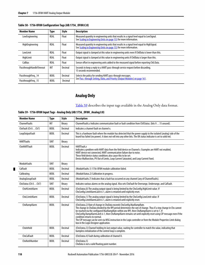
Chapter 7 1756-OF8H HART Analog Output Module
Analog Only
Table 59 describes the input tags available in the Analog Only data format.
LowEngineering REAL Float Measured quantity in engineering units that results in a signal level equal to LowSignal. See Scaling to Engineering Units on page 153 for more information.
HighEngineering REAL Float Measured quantity in engineering units that results in a signal level equal to HighSignal. See Scaling to Engineering Units on page 153 for more information.
LowLimit REAL Float Output signal is clamped at this value in engineering units even if Ch0Data is lower than this.
HighLimit REAL Float Output signal is clamped at this value in engineering units if Ch0Data is larger than this.
CalBias REAL Float Sensor offset in engineering units added to the measured signal before reporting Ch0.Data.
PassthroughHandleTimeout INT Decimal Seconds to keep a reply to a HART pass-through service request before discarding. 15 seconds recommended.
PassthroughFreq_14 BOOL Decimal Selects the policy for sending HART pass-through messages. See Pass -through Setting, Ratio, and Priority (Output Modules) on page 161.
PassthroughFreq_15 BOOL Decimal
Table 58 - 1756-OF8H Configuration Tags (AB:1756_OF8H:C:0)
Member Name Type Style Description
Table 59 - 1756-OF8H Input Tags - Analog Only (AB:1756_OF8H_Analog:I:0)
Member Name Type Style Description
ChannelFaults INT Binary ChannelFaults.x Indicates communication fault or fault condition from ChXStatus. (bits 9…15 unused).
ChxFault (Ch 0…Ch7) BOOL Decimal Indicates a channel fault on channel x.
LoopOutputFault BOOL Decimal This is a hardware fault where the module has detected that the power supply to the isolated (analog) side of the board has failed (no power). It does not roll into any other bits. The OK status indicator is set to solid red.
HARTFaults SINT Binary
ChxHARTFault BOOL Decimal HARTFault.xIndicates a problem with HART data from the field device on Channel x. Examples are HART not enabled, HART device not connected, HART communication failure due to noise.These field device status conditions also cause this to be set: Device Malfunction, PV Out of Limits, Loop Current Saturated, and Loop Current Fixed.
ModuleFaults SINT Binary
CalFault BOOL Decimal (ModuleFaults.1) 1756-OF8H module calibration failed.
Calibrating BOOL Decimal (ModuleStatus.2) Calibration in progress.
AnalogGroupFault BOOL Decimal (ModuleFaults.7) Indicates that a fault has occurred on any channel (any of ChannelFaults).
ChxStatus (Ch 0…Ch7) SINT Binary Indicates various alarms on the analog signal. Also sets ChxFault for Overrange, Underrange, and CalFault.
ChxHLimitAlarm BOOL Decimal (ChxStatus.0) The analog output signal is being limited by the ChxConfig.HighLimit value. If ChxConfig.LimitAlarmLatch is 1, alarm is retained until explicitly reset.
ChxLLimitAlarm BOOL Decimal (ChxStatus.1) The analog output signal is being limited by the ChxConfig.LowLimit value. If ChxConfig.LimitAlarmLatch is 1, alarm is retained until explicitly reset.
ChxRampAlarm BOOL Decimal (ChxStatus.2) Rate of change in ChxData exceeds ChxConfig.MaxRampRate. The change in ChxData divided by the RPI period determines the rate of change. Thus if a step change in Chx cannot be reached via the configured MaxRampRate within one RPI, then ChxRampAlarm is set to 1. If ChxConfig.RampAlarmLatch is 1, then ChxRampAlarm remains set until explicitly reset using CIP message even if the condition returns to normal. The CIP message can be sent via MSG instruction in the Logix controller or from the Module Properties Limit dialog box in the Logix Designer application.
ChxInHold BOOL Decimal (ChxStatus.3) Channel holding its last output value, waiting for controller to match the value, indicating that bumpless initialization of the control loop is complete.
ChxCalFault BOOL Decimal (ChxStatus.4) Fault during calibration of channel 0.
ChxNotANumber BOOL Decimal (ChxStatus.5) ChxData is not a valid floating point number.
118 Rockwell Automation Publication 1756-UM533E-EN-P - November 2016
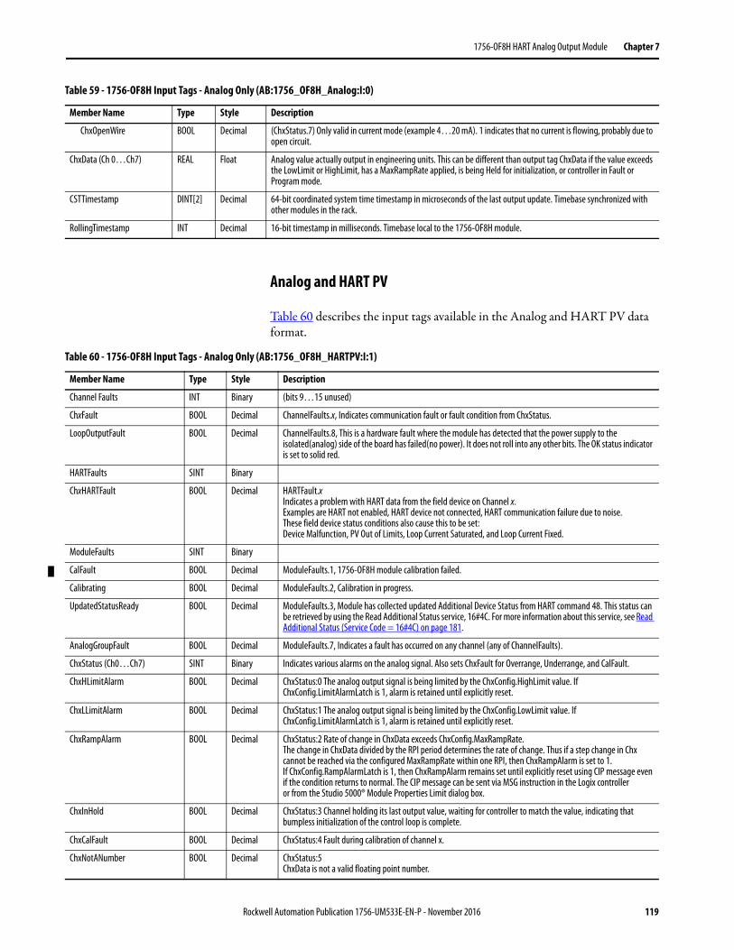
1756-OF8H HART Analog Output Module Chapter 7
Analog and HART PV
Table 60 describes the input tags available in the Analog and HART PV data format.
ChxOpenWire BOOL Decimal (ChxStatus.7) Only valid in current mode (example 4…20 mA). 1 indicates that no current is flowing, probably due to open circuit.
ChxData (Ch 0…Ch7) REAL Float Analog value actually output in engineering units. This can be different than output tag ChxData if the value exceeds the LowLimit or HighLimit, has a MaxRampRate applied, is being Held for initialization, or controller in Fault or Program mode.
CSTTimestamp DINT[2] Decimal 64-bit coordinated system time timestamp in microseconds of the last output update. Timebase synchronized with other modules in the rack.
RollingTimestamp INT Decimal 16-bit timestamp in milliseconds. Timebase local to the 1756-OF8H module.
Table 59 - 1756-OF8H Input Tags - Analog Only (AB:1756_OF8H_Analog:I:0)
Member Name Type Style Description
Table 60 - 1756-OF8H Input Tags - Analog Only (AB:1756_OF8H_HARTPV:I:1)
Member Name Type Style Description
Channel Faults INT Binary (bits 9…15 unused)
ChxFault BOOL Decimal ChannelFaults.x, Indicates communication fault or fault condition from ChxStatus.
LoopOutputFault BOOL Decimal ChannelFaults.8, This is a hardware fault where the module has detected that the power supply to the isolated(analog) side of the board has failed(no power). It does not roll into any other bits. The OK status indicator is set to solid red.
HARTFaults SINT Binary
ChxHARTFault BOOL Decimal HARTFault.xIndicates a problem with HART data from the field device on Channel x. Examples are HART not enabled, HART device not connected, HART communication failure due to noise.These field device status conditions also cause this to be set: Device Malfunction, PV Out of Limits, Loop Current Saturated, and Loop Current Fixed.
ModuleFaults SINT Binary
CalFault BOOL Decimal ModuleFaults.1, 1756-OF8H module calibration failed.
Calibrating BOOL Decimal ModuleFaults.2, Calibration in progress.
UpdatedStatusReady BOOL Decimal ModuleFaults.3, Module has collected updated Additional Device Status from HART command 48. This status can be retrieved by using the Read Additional Status service, 16#4C. For more information about this service, see Read Additional Status (Service Code = 16#4C) on page 181.
AnalogGroupFault BOOL Decimal ModuleFaults.7, Indicates a fault has occurred on any channel (any of ChannelFaults).
ChxStatus (Ch0…Ch7) SINT Binary Indicates various alarms on the analog signal. Also sets ChxFault for Overrange, Underrange, and CalFault.
ChxHLimitAlarm BOOL Decimal ChxStatus:0 The analog output signal is being limited by the ChxConfig.HighLimit value. If ChxConfig.LimitAlarmLatch is 1, alarm is retained until explicitly reset.
ChxLLimitAlarm BOOL Decimal ChxStatus:1 The analog output signal is being limited by the ChxConfig.LowLimit value. If ChxConfig.LimitAlarmLatch is 1, alarm is retained until explicitly reset.
ChxRampAlarm BOOL Decimal ChxStatus:2 Rate of change in ChxData exceeds ChxConfig.MaxRampRate. The change in ChxData divided by the RPI period determines the rate of change. Thus if a step change in Chx cannot be reached via the configured MaxRampRate within one RPI, then ChxRampAlarm is set to 1. If ChxConfig.RampAlarmLatch is 1, then ChxRampAlarm remains set until explicitly reset using CIP message even if the condition returns to normal. The CIP message can be sent via MSG instruction in the Logix controller or from the Studio 5000® Module Properties Limit dialog box.
ChxInHold BOOL Decimal ChxStatus:3 Channel holding its last output value, waiting for controller to match the value, indicating that bumpless initialization of the control loop is complete.
ChxCalFault BOOL Decimal ChxStatus:4 Fault during calibration of channel x.
ChxNotANumber BOOL Decimal ChxStatus:5 ChxData is not a valid floating point number.
Rockwell Automation Publication 1756-UM533E-EN-P - November 2016 119
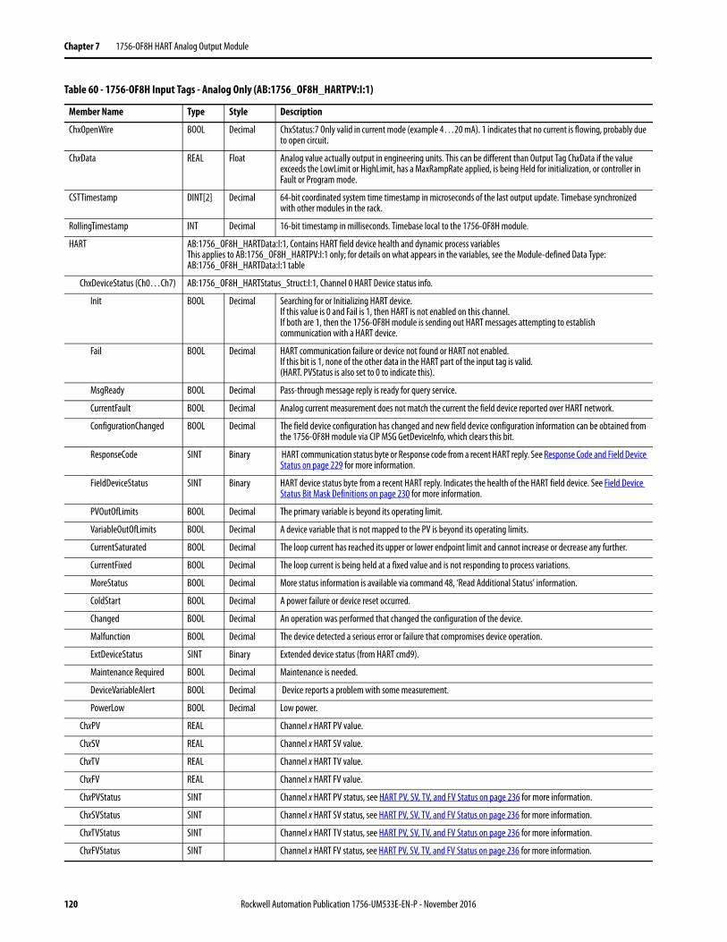
Chapter 7 1756-OF8H HART Analog Output Module
ChxOpenWire BOOL Decimal ChxStatus:7 Only valid in current mode (example 4…20 mA). 1 indicates that no current is flowing, probably due to open circuit.
ChxData REAL Float Analog value actually output in engineering units. This can be different than Output Tag ChxData if the value exceeds the LowLimit or HighLimit, has a MaxRampRate applied, is being Held for initialization, or controller in Fault or Program mode.
CSTTimestamp DINT[2] Decimal 64-bit coordinated system time timestamp in microseconds of the last output update. Timebase synchronized with other modules in the rack.
RollingTimestamp INT Decimal 16-bit timestamp in milliseconds. Timebase local to the 1756-OF8H module.
HART AB:1756_OF8H_HARTData:I:1, Contains HART field device health and dynamic process variablesThis applies to AB:1756_OF8H_HARTPV:I:1 only; for details on what appears in the variables, see the Module-defined Data Type: AB:1756_OF8H_HARTData:I:1 table
ChxDeviceStatus (Ch0…Ch7) AB:1756_OF8H_HARTStatus_Struct:I:1, Channel 0 HART Device status info.
Init BOOL Decimal Searching for or Initializing HART device. If this value is 0 and Fail is 1, then HART is not enabled on this channel. If both are 1, then the 1756-OF8H module is sending out HART messages attempting to establish communication with a HART device.
Fail BOOL Decimal HART communication failure or device not found or HART not enabled. If this bit is 1, none of the other data in the HART part of the input tag is valid. (HART. PVStatus is also set to 0 to indicate this).
MsgReady BOOL Decimal Pass-through message reply is ready for query service.
CurrentFault BOOL Decimal Analog current measurement does not match the current the field device reported over HART network.
ConfigurationChanged BOOL Decimal The field device configuration has changed and new field device configuration information can be obtained from the 1756-OF8H module via CIP MSG GetDeviceInfo, which clears this bit.
ResponseCode SINT Binary HART communication status byte or Response code from a recent HART reply. See Response Code and Field Device Status on page 229 for more information.
FieldDeviceStatus SINT Binary HART device status byte from a recent HART reply. Indicates the health of the HART field device. See Field Device Status Bit Mask Definitions on page 230 for more information.
PVOutOfLimits BOOL Decimal The primary variable is beyond its operating limit.
VariableOutOfLimits BOOL Decimal A device variable that is not mapped to the PV is beyond its operating limits.
CurrentSaturated BOOL Decimal The loop current has reached its upper or lower endpoint limit and cannot increase or decrease any further.
CurrentFixed BOOL Decimal The loop current is being held at a fixed value and is not responding to process variations.
MoreStatus BOOL Decimal More status information is available via command 48, ‘Read Additional Status’ information.
ColdStart BOOL Decimal A power failure or device reset occurred.
Changed BOOL Decimal An operation was performed that changed the configuration of the device.
Malfunction BOOL Decimal The device detected a serious error or failure that compromises device operation.
ExtDeviceStatus SINT Binary Extended device status (from HART cmd9).
Maintenance Required BOOL Decimal Maintenance is needed.
DeviceVariableAlert BOOL Decimal Device reports a problem with some measurement.
PowerLow BOOL Decimal Low power.
ChxPV REAL Channel x HART PV value.
ChxSV REAL Channel x HART SV value.
ChxTV REAL Channel x HART TV value.
ChxFV REAL Channel x HART FV value.
ChxPVStatus SINT Channel x HART PV status, see HART PV, SV, TV, and FV Status on page 236 for more information.
ChxSVStatus SINT Channel x HART SV status, see HART PV, SV, TV, and FV Status on page 236 for more information.
ChxTVStatus SINT Channel x HART TV status, see HART PV, SV, TV, and FV Status on page 236 for more information.
ChxFVStatus SINT Channel x HART FV status, see HART PV, SV, TV, and FV Status on page 236 for more information.
Table 60 - 1756-OF8H Input Tags - Analog Only (AB:1756_OF8H_HARTPV:I:1)
Member Name Type Style Description
120 Rockwell Automation Publication 1756-UM533E-EN-P - November 2016
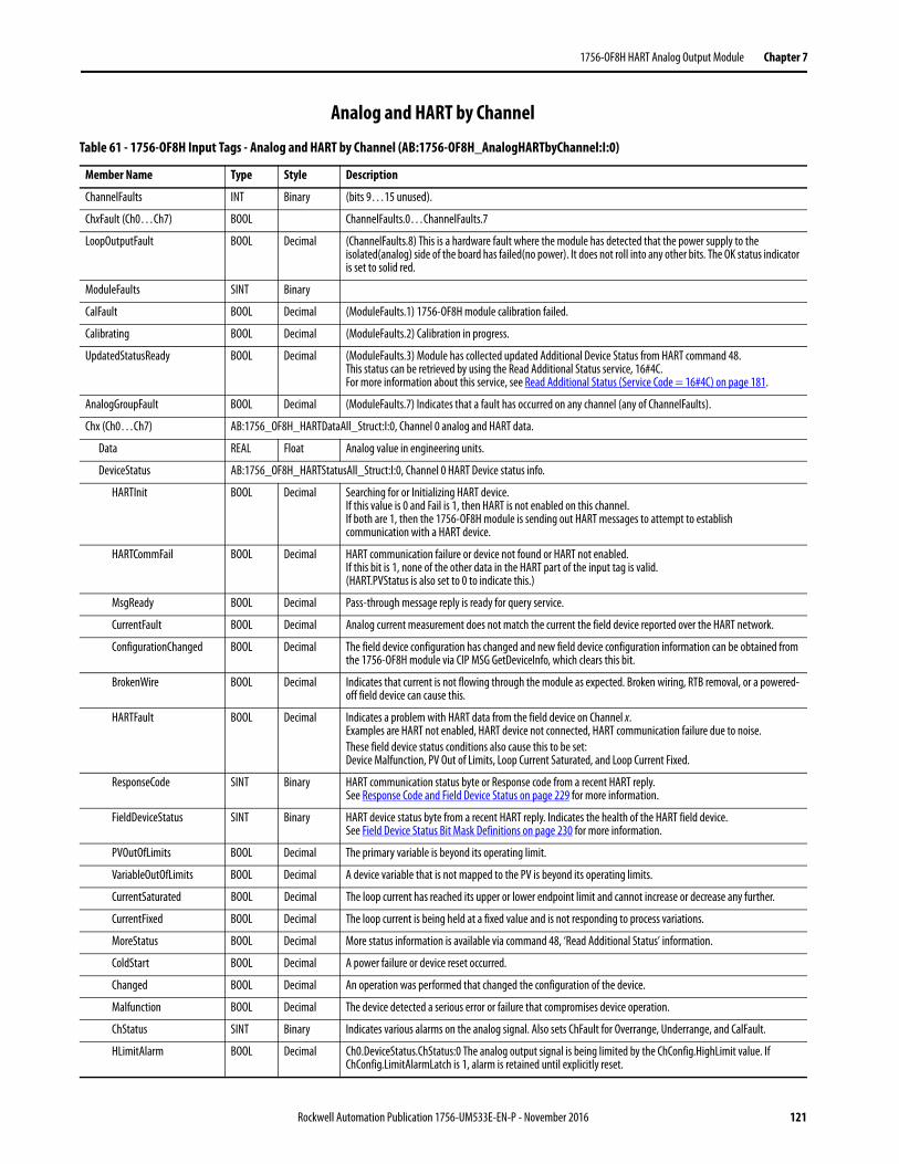
1756-OF8H HART Analog Output Module Chapter 7
Analog and HART by Channel
Table 61 - 1756-OF8H Input Tags - Analog and HART by Channel (AB:1756-OF8H_AnalogHARTbyChannel:I:0)
Member Name Type Style Description
ChannelFaults INT Binary (bits 9…15 unused).
ChxFault (Ch0…Ch7) BOOL ChannelFaults.0…ChannelFaults.7
LoopOutputFault BOOL Decimal (ChannelFaults.8) This is a hardware fault where the module has detected that the power supply to the isolated(analog) side of the board has failed(no power). It does not roll into any other bits. The OK status indicator is set to solid red.
ModuleFaults SINT Binary
CalFault BOOL Decimal (ModuleFaults.1) 1756-OF8H module calibration failed.
Calibrating BOOL Decimal (ModuleFaults.2) Calibration in progress.
UpdatedStatusReady BOOL Decimal (ModuleFaults.3) Module has collected updated Additional Device Status from HART command 48. This status can be retrieved by using the Read Additional Status service, 16#4C. For more information about this service, see Read Additional Status (Service Code = 16#4C) on page 181.
AnalogGroupFault BOOL Decimal (ModuleFaults.7) Indicates that a fault has occurred on any channel (any of ChannelFaults).
Chx (Ch0…Ch7) AB:1756_OF8H_HARTDataAll_Struct:I:0, Channel 0 analog and HART data.
Data REAL Float Analog value in engineering units.
DeviceStatus AB:1756_OF8H_HARTStatusAll_Struct:I:0, Channel 0 HART Device status info.
HARTInit BOOL Decimal Searching for or Initializing HART device. If this value is 0 and Fail is 1, then HART is not enabled on this channel. If both are 1, then the 1756-OF8H module is sending out HART messages to attempt to establish communication with a HART device.
HARTCommFail BOOL Decimal HART communication failure or device not found or HART not enabled. If this bit is 1, none of the other data in the HART part of the input tag is valid. (HART.PVStatus is also set to 0 to indicate this.)
MsgReady BOOL Decimal Pass-through message reply is ready for query service.
CurrentFault BOOL Decimal Analog current measurement does not match the current the field device reported over the HART network.
ConfigurationChanged BOOL Decimal The field device configuration has changed and new field device configuration information can be obtained from the 1756-OF8H module via CIP MSG GetDeviceInfo, which clears this bit.
BrokenWire BOOL Decimal Indicates that current is not flowing through the module as expected. Broken wiring, RTB removal, or a powered-off field device can cause this.
HARTFault BOOL Decimal Indicates a problem with HART data from the field device on Channel x. Examples are HART not enabled, HART device not connected, HART communication failure due to noise.These field device status conditions also cause this to be set: Device Malfunction, PV Out of Limits, Loop Current Saturated, and Loop Current Fixed.
ResponseCode SINT Binary HART communication status byte or Response code from a recent HART reply. See Response Code and Field Device Status on page 229 for more information.
FieldDeviceStatus SINT Binary HART device status byte from a recent HART reply. Indicates the health of the HART field device. See Field Device Status Bit Mask Definitions on page 230 for more information.
PVOutOfLimits BOOL Decimal The primary variable is beyond its operating limit.
VariableOutOfLimits BOOL Decimal A device variable that is not mapped to the PV is beyond its operating limits.
CurrentSaturated BOOL Decimal The loop current has reached its upper or lower endpoint limit and cannot increase or decrease any further.
CurrentFixed BOOL Decimal The loop current is being held at a fixed value and is not responding to process variations.
MoreStatus BOOL Decimal More status information is available via command 48, ‘Read Additional Status’ information.
ColdStart BOOL Decimal A power failure or device reset occurred.
Changed BOOL Decimal An operation was performed that changed the configuration of the device.
Malfunction BOOL Decimal The device detected a serious error or failure that compromises device operation.
ChStatus SINT Binary Indicates various alarms on the analog signal. Also sets ChFault for Overrange, Underrange, and CalFault.
HLimitAlarm BOOL Decimal Ch0.DeviceStatus.ChStatus:0 The analog output signal is being limited by the ChConfig.HighLimit value. If ChConfig.LimitAlarmLatch is 1, alarm is retained until explicitly reset.
Rockwell Automation Publication 1756-UM533E-EN-P - November 2016 121
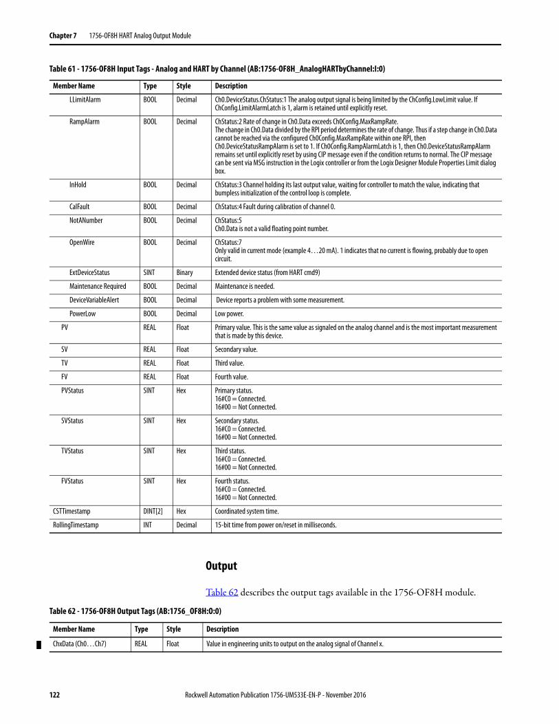
Chapter 7 1756-OF8H HART Analog Output Module
Output
Table 62 describes the output tags available in the 1756-OF8H module.
LLimitAlarm BOOL Decimal Ch0.DeviceStatus.ChStatus:1 The analog output signal is being limited by the ChConfig.LowLimit value. If ChConfig.LimitAlarmLatch is 1, alarm is retained until explicitly reset.
RampAlarm BOOL Decimal ChStatus:2 Rate of change in Ch0.Data exceeds Ch0Config.MaxRampRate. The change in Ch0.Data divided by the RPI period determines the rate of change. Thus if a step change in Ch0.Data cannot be reached via the configured Ch0Config.MaxRampRate within one RPI, then Ch0.DeviceStatusRampAlarm is set to 1. If Ch0Config.RampAlarmLatch is 1, then Ch0.DeviceStatusRampAlarm remains set until explicitly reset by using CIP message even if the condition returns to normal. The CIP message can be sent via MSG instruction in the Logix controller or from the Logix Designer Module Properties Limit dialog box.
InHold BOOL Decimal ChStatus:3 Channel holding its last output value, waiting for controller to match the value, indicating that bumpless initialization of the control loop is complete.
CalFault BOOL Decimal ChStatus:4 Fault during calibration of channel 0.
NotANumber BOOL Decimal ChStatus:5 Ch0.Data is not a valid floating point number.
OpenWire BOOL Decimal ChStatus:7 Only valid in current mode (example 4…20 mA). 1 indicates that no current is flowing, probably due to open circuit.
ExtDeviceStatus SINT Binary Extended device status (from HART cmd9)
Maintenance Required BOOL Decimal Maintenance is needed.
DeviceVariableAlert BOOL Decimal Device reports a problem with some measurement.
PowerLow BOOL Decimal Low power.
PV REAL Float Primary value. This is the same value as signaled on the analog channel and is the most important measurement that is made by this device.
SV REAL Float Secondary value.
TV REAL Float Third value.
FV REAL Float Fourth value.
PVStatus SINT Hex Primary status.16#C0 = Connected.16#00 = Not Connected.
SVStatus SINT Hex Secondary status.16#C0 = Connected.16#00 = Not Connected.
TVStatus SINT Hex Third status.16#C0 = Connected.16#00 = Not Connected.
FVStatus SINT Hex Fourth status.16#C0 = Connected.16#00 = Not Connected.
CSTTimestamp DINT[2] Hex Coordinated system time.
RollingTimestamp INT Decimal 15-bit time from power on/reset in milliseconds.
Table 61 - 1756-OF8H Input Tags - Analog and HART by Channel (AB:1756-OF8H_AnalogHARTbyChannel:I:0)
Member Name Type Style Description
Table 62 - 1756-OF8H Output Tags (AB:1756_OF8H:O:0)
Member Name Type Style Description
ChxData (Ch0…Ch7) REAL Float Value in engineering units to output on the analog signal of Channel x.
122 Rockwell Automation Publication 1756-UM533E-EN-P - November 2016
Chapter 8
1756-OF8IH HART Analog Output Module
Module Features The 1756-OF8IH module has the following features:• Eight individually controllable output channels with an individual
HART modem per channel• HART pass-through interface• Two output ranges (0…20 mA, 4…20 mA)• Auto-scanning of HART variables (PV, SV, TV, FV)• Option to auto-configure a HART device with user-specified PV
damping value, PV upper and lower range values, PV transfer function, and PV units code
• Write HART variables interface for some variables• Output data scaling• Time stamping• Floating point output data• Ramping (rate limiting)• Choice of four data formats
• Analog Only• Analog and HART PV• Analog and HART by Channel with Configure HART Device = Yes• Analog and HART by Channel with Configure HART Device = No
• User calibration via CIP messaging or output word• 15-bit or 16-bit resolution• Hold for initialization• Open wire detection• Clamp limit alarms• Data echo
Topic Page
Module Features 123
Wire the Module 128
Output Circuit Diagram 128
1756-OF8IH Module Fault and Status Reporting 129
Module Calibration 133
Module-defined Data Types, 1756-OF8IH Module 134
Rockwell Automation Publication 1756-UM533E-EN-P - November 2016 123
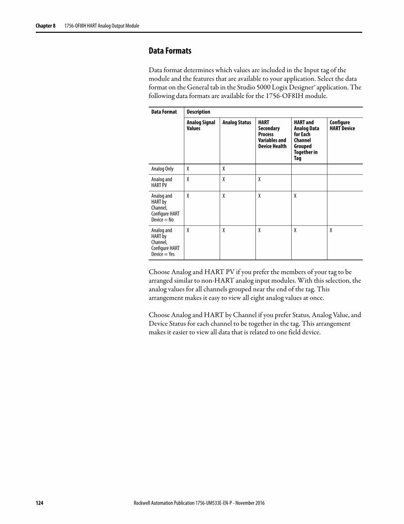
Chapter 8 1756-OF8IH HART Analog Output Module
Data Formats
Data format determines which values are included in the Input tag of the module and the features that are available to your application. Select the data format on the General tab in the Studio 5000 Logix Designer® application. The following data formats are available for the 1756-OF8IH module.
Choose Analog and HART PV if you prefer the members of your tag to be arranged similar to non-HART analog input modules. With this selection, the analog values for all channels grouped near the end of the tag. This arrangement makes it easy to view all eight analog values at once.
Choose Analog and HART by Channel if you prefer Status, Analog Value, and Device Status for each channel to be together in the tag. This arrangement makes it easier to view all data that is related to one field device.
Data Format Description
Analog Signal Values
Analog Status HART Secondary Process Variables and Device Health
HART and Analog Data for Each Channel Grouped Together in Tag
Configure HART Device
Analog Only X X
Analog and HART PV
X X X
Analog and HART by Channel, Configure HART Device = No
X X X X
Analog and HART by Channel, Configure HART Device = Yes
X X X X X
124 Rockwell Automation Publication 1756-UM533E-EN-P - November 2016
1756-OF8IH HART Analog Output Module Chapter 8
Powerup State
On powerup, the outputs of the 1756-OF8IH module are set to their reset state (0 mA) until module diagnostics and configuration are complete. Outputs are then set at their configured program values (ChxConfig.ProgValue).
Fault Mode Output State
You can choose the output state to be used when the module enters fault mode:
• Hold Last State• User-defined Value (you can choose either to ramp to a specified value
or to switch immediately to that value)
Ramping (Rate Limiting)
Ramping limits the rate at which an analog output signal can change. This feature prevents fast transitions in the output from damaging the devices that an output module controls.
The maximum rate of change in outputs is expressed in engineering units per second and called the maximum ramp rate.
For more information about ramp rate, see Chapter 9, Configure Modules in the Logix Designer Application.
Table 63 - Ramping Types
Ramping Types Description
Ramp-to-Run When the module is in Run mode, it limits the rate at which the output changes from one commanded value to another.
Ramp-to-Program When the controller goes into program mode, the present output value ramps to the configured Program Value. If the connection to the module is inhibited, the Program mode value and ramp rate are applied.
Ramp-to-Fault When a communication fault occurs, the output signal ramps to the configured fault value.
Rockwell Automation Publication 1756-UM533E-EN-P - November 2016 125
Chapter 8 1756-OF8IH HART Analog Output Module
Hold for Initialization
Hold for Initialization causes outputs to hold present state until the value that the controller commands matches the value at the output terminal within 0.1% of full scale. This feature helps provide a bumpless transfer.
If Hold for Initialization is selected, outputs hold if any of these conditions occur:
• Initial connection is established after power-up.• A new connection is established after a communication fault occurs.• There is a transition from Program mode to Run mode.
The ChxInHold bit for a channel indicates that the channel is holding.
Open Wire Detection
This feature detects when current flow is not present at the channel. At least 0.1 mA of current must be flowing from the output for detection to occur.
When an open wire condition occurs at any channel, a status bit named ChxOpenWire is set for that channel.
Clamping (Limiting)
Clamping limits the output from the analog module to remain within a range that the controller configures, even when the controller commands an output outside that range. This safety feature sets a high clamp value and a low clamp value.
Once clamps are set for a channel, data from the controller that exceeds the clamp values sets a limit alarm. The output transitions to that limit but not beyond the configured clamp value. For example, suppose that an application sets the high clamp on a module for 18 mA and the low clamp for 4 mA. If a controller sends a value that corresponds to 19 mA to the module, the module only applies 18 mA via its screw terminals. The signal value that is applied is reflected in the Input Tag ChxData field.
Clamping limits are entered in engineering units.
126 Rockwell Automation Publication 1756-UM533E-EN-P - November 2016
1756-OF8IH HART Analog Output Module Chapter 8
Clamp and Limit AlarmsThis function works directly with clamping. When a module receives a data value from the controller that exceeds clamping limits, it applies the clamping limit to the signal value and sends a status bit to the controller. This action notifies the controller that the commanded output data value exceeds the clamping limits.
For example, if a channel has a clamping limit of 18 mA but receives data to apply 19 mA, only 18 mA is applied via the screw terminals. The module sends a status bit to the controller to inform it that the 19 mA value exceeds the clamping limits of the channel.
Clamping alarms can be disabled or latched on a per channel basis. Clamping limits are entered in engineering units.
Data EchoData Echo automatically multicasts channel data values that match the analog value that is applied to the module screw terminals.
Fault and status data are also sent. If selected in the Input Data format, HART secondary process variables and device health are also sent.
An example is that I.ChxData is the echo of O.ChxData. They can be different due to Ramp, Clamp, or Hold for Initialization.
The echo value is the current level being attempted. If the wire is off or damaged, the actual current can be 0.
HART Device Auto-configuration
A HART device can be automatically configured with user-specified PV damping, PV range limits and units, and PV transfer function values. If enabled, configuration occurs when the device is connected or when the module detects that one of two configuration bits is set. There is a separate configuration bit for PV damping value, and another for PV upper and lower range values, PV transfer function, and PV range units.
This feature is available only with the Analog and HART by Channel data format with Configure HART Device = Yes.
Write HART Variables
The module supports setting a limited number of HART variables via special use of the pass-through interface. See Chapter 10, Use a CIP MSG to get HART Data, for more information.
Rockwell Automation Publication 1756-UM533E-EN-P - November 2016 127
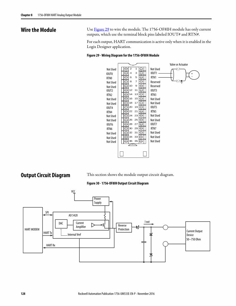
Chapter 8 1756-OF8IH HART Analog Output Module
Wire the Module Use Figure 29 to wire the module. The 1756-OF8IH module has only current outputs, which use the terminal block pins labeled IOUT# and RTN#.
For each output, HART communication is active only when it is enabled in the Logix Designer application.
Figure 29 - Wiring Diagram for the 1756-OF8IH Module
Output Circuit Diagram This section shows the module output circuit diagram.
Figure 30 - 1756-OF8IH Output Circuit Diagram
2
4
6
8
10
12
14
16
18
20
22
24
26
28
30
32
34
36
1
3
5
7
9
11
13
15
17
19
21
23
25
27
29
31
33
35
Valve or Actuator
ReservedReserved
Not Used
Not UsedNot Used
Not UsedNot Used
Not UsedNot UsedNot Used
Not Used
Not UsedNot Used
Not UsedNot Used
Not UsedNot Used
Not Used
Not UsedNot Used
IOUT2RTN2
IOUT4RTN4
IOUT6RTN6
IOUT0RTN0
IOUT1RTN1
IOUT3RTN3
IOUT5RTN5
IOUT7RTN7
Power Supply
Reverse Protection
Power Supply
Current Amplifier
Internal Vref
HART Rx
HART Tx
SPI
VCC
AD 5420
DAC
HART MODEM
I out
Current Output Device50~750 Ohm
128 Rockwell Automation Publication 1756-UM533E-EN-P - November 2016
1756-OF8IH HART Analog Output Module Chapter 8
1756-OF8IH Module Fault and Status Reporting
The 1756-OF8IH modules multicast status and fault data to the controller with their channel data. The fault data is arranged to let you choose the level of granularity you desire for examining fault conditions.
Three levels of tags work together to provide increasing degree of detail as to the specific cause of faults on the module.
Table 64 lists tags that you can examine in ladder logic to indicate when a fault occurred.
Table 64 - 1756-OF8IH Tags That Can Be Examined in Ladder Logic
Tag Description Tag NameAnalog and HART PV
Tag NameAnalog and HART by Channel
Module Fault Word The bits in this word are set when a fault of the corresponding type has occurred on any channel.
ModuleFaults ModuleFaults
Channel Fault Word These bits report faults that occur on the corresponding channel.
ChannelFaultsChxFault
ChannelFaultsChxFault
Channel Status Tags These words, one per channel, indicate individual channel limit, hold, open wire, ramp status, and calibration faults.
ChxStatus Chx.DeviceStatusChx.DeviceStatus.AlarmStatus
HART Faults The bits in this word show HART communication status for each channel.
HARTFaults, ChxHARTFault Chx.DeviceStatus.HARTFault
HART Device Status This data provides information about the HART field device. HART.ChxDevice Status Chx.DeviceStatus.FieldDeviceStatus
Rockwell Automation Publication 1756-UM533E-EN-P - November 2016 129
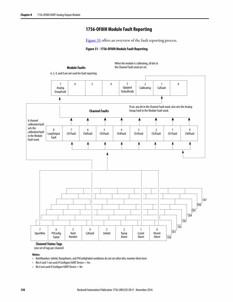
Chapter 8 1756-OF8IH HART Analog Output Module
1756-OF8IH Module Fault Reporting
Figure 31 offers an overview of the fault reporting process.
Figure 31 - 1756-OF8IH Module Fault Reporting
Module Faults
Channel Faults
Channel Status Tags(one set of tags per channel)
7Analog
GroupFault
6 5 4
6, 5, 4, and 0 are not used for fault reporting
Notes:• NotANumber, InHold, RampAlarm, and PVConfigFailed conditions do not set other bits; monitor them here.• Bits 0 and 1 not used if Configure HART Device = Yes• Bit 6 not used if Configure HART Device = No
If set, any bit in the Channel Fault word, also sets the Analog Group Fault in the Module Fault word.
A channel calibration fault sets the calibration fault in the Module Fault word.
When the module is calibrating, all bits in the Channel Fault word are set.
7Ch7Fault
6Ch6Fault
5Ch5Fault
4Ch4Fault
3Ch3Fault
2Ch2Fault
1Ch1Fault
0Ch0Fault
7OpenWire
6PVConfig
Failed
5NotA
Number
4CalFault
3InHold
2RampAlarm
1LLimitAlarm
0HLimitAlarm Ch0
Ch1
Ch2
Ch3
Ch4
Ch5
Ch6Ch7
2Calibrating
1CalFault
0
8LoopOutput
Fault
3Updated
StatusReady
130 Rockwell Automation Publication 1756-UM533E-EN-P - November 2016
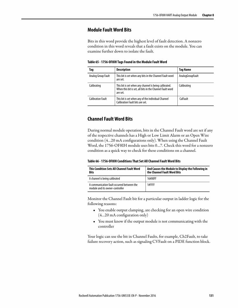
1756-OF8IH HART Analog Output Module Chapter 8
Module Fault Word Bits
Bits in this word provide the highest level of fault detection. A nonzero condition in this word reveals that a fault exists on the module. You can examine further down to isolate the fault.
Channel Fault Word Bits
During normal module operation, bits in the Channel Fault word are set if any of the respective channels has a High or Low Limit Alarm or an Open Wire condition (4…20 mA configurations only). When using the Channel Fault Word, the 1756-OF8IH module uses bits 0…7. Check this word for a nonzero condition as a quick way to check for these conditions on a channel.
Monitor the Channel Fault bit for a particular output in ladder logic for the following reasons:
• You enable output clamping, are checking for an open wire condition (4…20 mA configuration only)
• You must know if the output module is not communicating with the controller
Your logic can use the bit in Channel Faults, for example, Ch2Fault, to take failure recovery action, such as signaling CVFault on a PIDE function block.
Table 65 - 1756-OF8IH Tags Found in the Module Fault Word
Tag Description Tag Name
Analog Group Fault This bit is set when any bits in the Channel Fault word are set.
AnalogGroupFault
Calibrating This bit is set when any channel is being calibrated. When this bit is set, all bits in the Channel Fault word are set.
Calibrating
Calibration Fault This bit is set when any of the individual Channel Calibration Fault bits are set.
CalFault
Table 66 - 1756-OF8IH Conditions That Set All Channel Fault Word Bits
This Condition Sets All Channel Fault Word Bits
And Causes the Module to Display the Following in the Channel Fault Word Bits
A channel is being calibrated 16#00FF
A communication fault occurred between the module and its owner-controller
1#FFFF
Rockwell Automation Publication 1756-UM533E-EN-P - November 2016 131
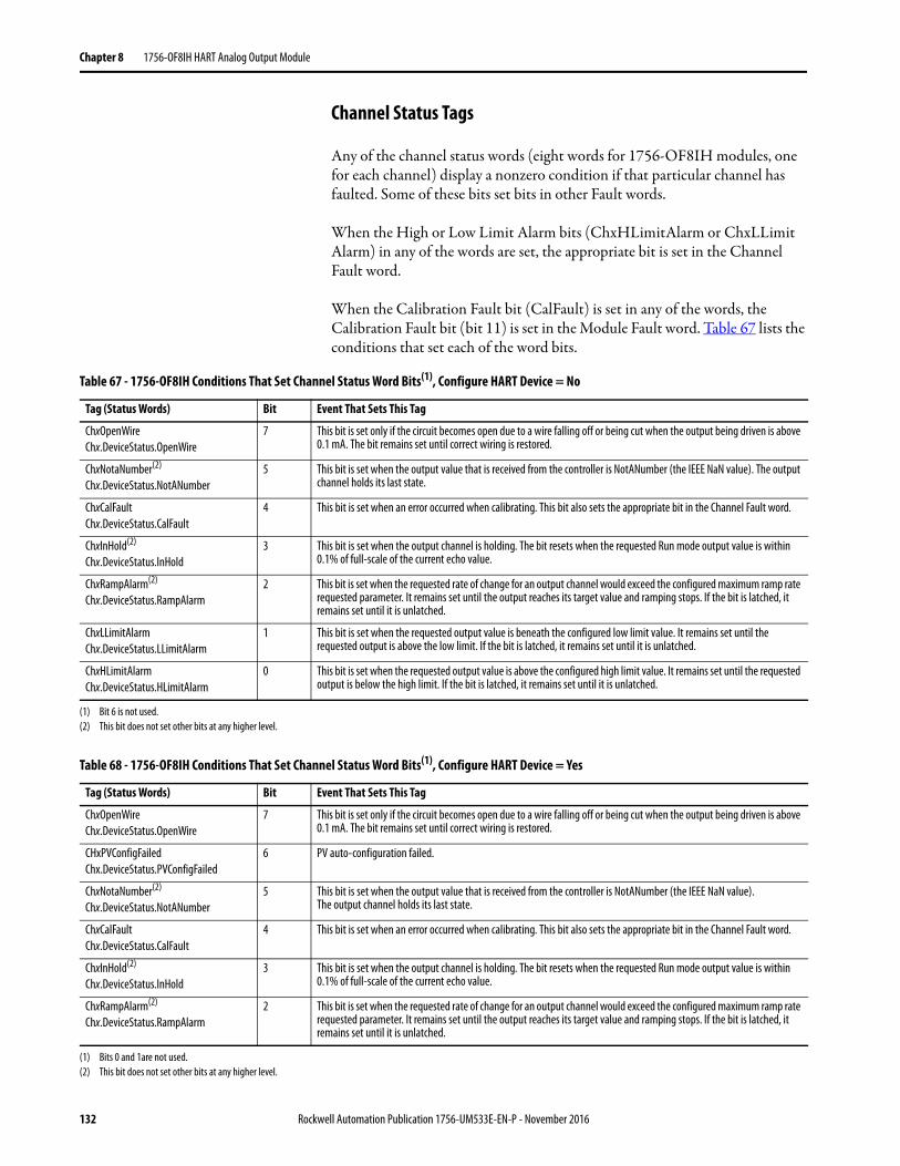
Chapter 8 1756-OF8IH HART Analog Output Module
Channel Status Tags
Any of the channel status words (eight words for 1756-OF8IH modules, one for each channel) display a nonzero condition if that particular channel has faulted. Some of these bits set bits in other Fault words.
When the High or Low Limit Alarm bits (ChxHLimitAlarm or ChxLLimit Alarm) in any of the words are set, the appropriate bit is set in the Channel Fault word.
When the Calibration Fault bit (CalFault) is set in any of the words, the Calibration Fault bit (bit 11) is set in the Module Fault word. Table 67 lists the conditions that set each of the word bits.
Table 67 - 1756-OF8IH Conditions That Set Channel Status Word Bits(1), Configure HART Device = No
Tag (Status Words) Bit Event That Sets This Tag
ChxOpenWireChx.DeviceStatus.OpenWire
7 This bit is set only if the circuit becomes open due to a wire falling off or being cut when the output being driven is above 0.1 mA. The bit remains set until correct wiring is restored.
ChxNotaNumber(2)
Chx.DeviceStatus.NotANumber5 This bit is set when the output value that is received from the controller is NotANumber (the IEEE NaN value). The output
channel holds its last state.
ChxCalFaultChx.DeviceStatus.CalFault
4 This bit is set when an error occurred when calibrating. This bit also sets the appropriate bit in the Channel Fault word.
ChxInHold(2)
Chx.DeviceStatus.InHold3 This bit is set when the output channel is holding. The bit resets when the requested Run mode output value is within
0.1% of full-scale of the current echo value.
ChxRampAlarm(2)
Chx.DeviceStatus.RampAlarm2 This bit is set when the requested rate of change for an output channel would exceed the configured maximum ramp rate
requested parameter. It remains set until the output reaches its target value and ramping stops. If the bit is latched, it remains set until it is unlatched.
ChxLLimitAlarmChx.DeviceStatus.LLimitAlarm
1 This bit is set when the requested output value is beneath the configured low limit value. It remains set until the requested output is above the low limit. If the bit is latched, it remains set until it is unlatched.
ChxHLimitAlarmChx.DeviceStatus.HLimitAlarm
0 This bit is set when the requested output value is above the configured high limit value. It remains set until the requested output is below the high limit. If the bit is latched, it remains set until it is unlatched.
(1) Bit 6 is not used.(2) This bit does not set other bits at any higher level.
Table 68 - 1756-OF8IH Conditions That Set Channel Status Word Bits(1), Configure HART Device = Yes
Tag (Status Words) Bit Event That Sets This Tag
ChxOpenWireChx.DeviceStatus.OpenWire
7 This bit is set only if the circuit becomes open due to a wire falling off or being cut when the output being driven is above 0.1 mA. The bit remains set until correct wiring is restored.
CHxPVConfigFailedChx.DeviceStatus.PVConfigFailed
6 PV auto-configuration failed.
ChxNotaNumber(2)
Chx.DeviceStatus.NotANumber5 This bit is set when the output value that is received from the controller is NotANumber (the IEEE NaN value).
The output channel holds its last state.
ChxCalFaultChx.DeviceStatus.CalFault
4 This bit is set when an error occurred when calibrating. This bit also sets the appropriate bit in the Channel Fault word.
ChxInHold(2)
Chx.DeviceStatus.InHold3 This bit is set when the output channel is holding. The bit resets when the requested Run mode output value is within
0.1% of full-scale of the current echo value.
ChxRampAlarm(2)
Chx.DeviceStatus.RampAlarm2 This bit is set when the requested rate of change for an output channel would exceed the configured maximum ramp rate
requested parameter. It remains set until the output reaches its target value and ramping stops. If the bit is latched, it remains set until it is unlatched.
(1) Bits 0 and 1are not used.(2) This bit does not set other bits at any higher level.
132 Rockwell Automation Publication 1756-UM533E-EN-P - November 2016
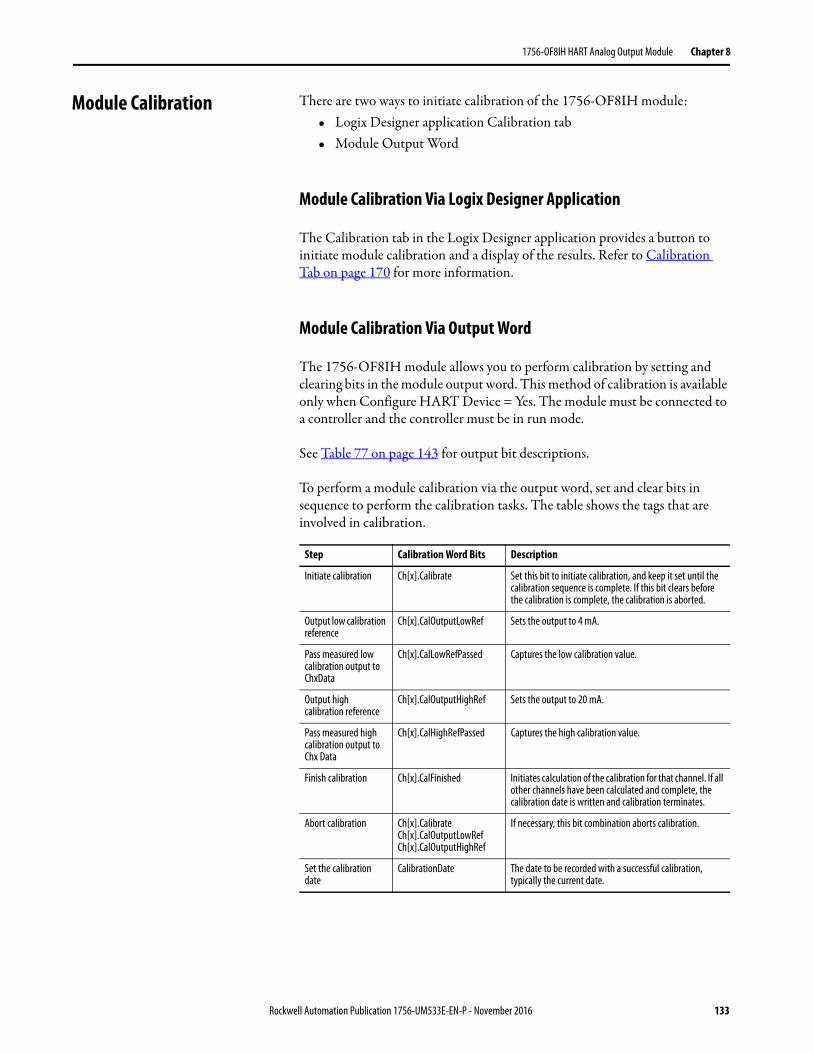
1756-OF8IH HART Analog Output Module Chapter 8
Module Calibration There are two ways to initiate calibration of the 1756-OF8IH module:• Logix Designer application Calibration tab• Module Output Word
Module Calibration Via Logix Designer Application
The Calibration tab in the Logix Designer application provides a button to initiate module calibration and a display of the results. Refer to Calibration Tab on page 170 for more information.
Module Calibration Via Output Word
The 1756-OF8IH module allows you to perform calibration by setting and clearing bits in the module output word. This method of calibration is available only when Configure HART Device = Yes. The module must be connected to a controller and the controller must be in run mode.
See Table 77 on page 143 for output bit descriptions.
To perform a module calibration via the output word, set and clear bits in sequence to perform the calibration tasks. The table shows the tags that are involved in calibration.
Step Calibration Word Bits Description
Initiate calibration Ch[x].Calibrate Set this bit to initiate calibration, and keep it set until the calibration sequence is complete. If this bit clears before the calibration is complete, the calibration is aborted.
Output low calibration reference
Ch[x].CalOutputLowRef Sets the output to 4 mA.
Pass measured low calibration output to ChxData
Ch[x].CalLowRefPassed Captures the low calibration value.
Output high calibration reference
Ch[x].CalOutputHighRef Sets the output to 20 mA.
Pass measured high calibration output to Chx Data
Ch[x].CalHighRefPassed Captures the high calibration value.
Finish calibration Ch[x].CalFinished Initiates calculation of the calibration for that channel. If all other channels have been calculated and complete, the calibration date is written and calibration terminates.
Abort calibration Ch[x].CalibrateCh[x].CalOutputLowRefCh[x].CalOutputHighRef
If necessary, this bit combination aborts calibration.
Set the calibration date
CalibrationDate The date to be recorded with a successful calibration, typically the current date.
Rockwell Automation Publication 1756-UM533E-EN-P - November 2016 133
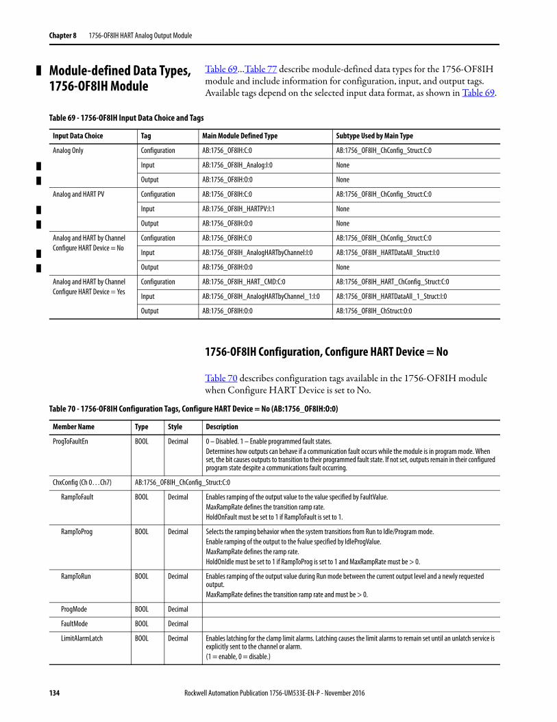
Chapter 8 1756-OF8IH HART Analog Output Module
Module-defined Data Types, 1756-OF8IH Module
Table 69…Table 77 describe module-defined data types for the 1756-OF8IH module and include information for configuration, input, and output tags.Available tags depend on the selected input data format, as shown in Table 69.
1756-OF8IH Configuration, Configure HART Device = No
Table 70 describes configuration tags available in the 1756-OF8IH module when Configure HART Device is set to No.
Table 69 - 1756-OF8IH Input Data Choice and Tags
Input Data Choice Tag Main Module Defined Type Subtype Used by Main Type
Analog Only Configuration AB:1756_OF8IH:C:0 AB:1756_OF8IH_ChConfig_Struct:C:0
Input AB:1756_OF8IH_Analog:I:0 None
Output AB:1756_OF8IH:O:0 None
Analog and HART PV Configuration AB:1756_OF8IH:C:0 AB:1756_OF8IH_ChConfig_Struct:C:0
Input AB:1756_OF8IH_HARTPV:I:1 None
Output AB:1756_OF8IH:O:0 None
Analog and HART by ChannelConfigure HART Device = No
Configuration AB:1756_OF8IH:C:0 AB:1756_OF8IH_ChConfig_Struct:C:0
Input AB:1756_OF8IH_AnalogHARTbyChannel:I:0 AB:1756_OF8IH_HARTDataAll_Struct:I:0
Output AB:1756_OF8IH:O:0 None
Analog and HART by ChannelConfigure HART Device = Yes
Configuration AB:1756_OF8IH_HART_CMD:C:0 AB:1756_OF8IH_HART_ChConfig_Struct:C:0
Input AB:1756_OF8IH_AnalogHARTbyChannel_1:I:0 AB:1756_OF8IH_HARTDataAll_1_Struct:I:0
Output AB:1756_OF8IH:O:0 AB:1756_OF8IH_ChStruct:O:0
Table 70 - 1756-OF8IH Configuration Tags, Configure HART Device = No (AB:1756_OF8IH:O:0)
Member Name Type Style Description
ProgToFaultEn BOOL Decimal 0 – Disabled. 1 – Enable programmed fault states.Determines how outputs can behave if a communication fault occurs while the module is in program mode. When set, the bit causes outputs to transition to their programmed fault state. If not set, outputs remain in their configured program state despite a communications fault occurring.
ChxConfig (Ch 0…Ch7) AB:1756_OF8IH_ChConfig_Struct:C:0
RampToFault BOOL Decimal Enables ramping of the output value to the value specified by FaultValue.MaxRampRate defines the transition ramp rate.HoldOnFault must be set to 1 if RampToFault is set to 1.
RampToProg BOOL Decimal Selects the ramping behavior when the system transitions from Run to Idle/Program mode.Enable ramping of the output to the fvalue specified by IdleProgValue.MaxRampRate defines the ramp rate.HoldOnIdle must be set to 1 if RampToProg is set to 1 and MaxRampRate must be > 0.
RampToRun BOOL Decimal Enables ramping of the output value during Run mode between the current output level and a newly requested output.MaxRampRate defines the transition ramp rate and must be > 0.
ProgMode BOOL Decimal
FaultMode BOOL Decimal
LimitAlarmLatch BOOL Decimal Enables latching for the clamp limit alarms. Latching causes the limit alarms to remain set until an unlatch service is explicitly sent to the channel or alarm.(1 = enable, 0 = disable.)
134 Rockwell Automation Publication 1756-UM533E-EN-P - November 2016
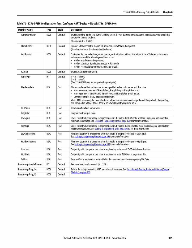
1756-OF8IH HART Analog Output Module Chapter 8
RampAlarmLatch BOOL Decimal Enables latching for the rate alarm. Latching causes the rate alarm to remain set until an unlatch service is explicitly sent to the channel or alarm. (1 = enable, 0 = disable.)
AlarmDisable BOOL Decimal Disables all alarms for the channel: HLimitAlarm, LLimitAlarm, RampAlarm.(1 = disable alarms, 0 = do not disable alarms.)
HoldForInit BOOL Decimal Configures the channel to hold, or not change, until initialized with a value within 0.1% of full scale or its current value when one of the following conditions occurs:• Module initial connection powerup.• Module transition from Program mode to Run mode.• Module re-establishes communication after a fault.
HARTEn BOOL Decimal Enables HART communication.
RangeType INT Decimal 1 = 0…20 mA.2 = 4…20 mA.(The 1756-OF8IH does not support voltage outputs.)
MaxRampRate REAL Float Maximum allowable transition rate in user-specified scaling units per second. The value:• Must be greater than zero if RampToFault, RampToProg, or RampToRun is set. • Must equal zero if RampToFault, RampToProg, and RampToRun are all not set.• Cannot be greater than 2 x full scale maximum.When HART is enabled, the channel enforces a fixed maximum ramp rate regardless of RampToFault, RampToProg, and RampToRun settings; this is done to help avoid HART transmission noise.
FaultValue REAL Float Communication fault output value.
ProgValue REAL Float Program mode output value.
LowSignal REAL Float Lower current value for scaling to engineering units. Default is 4 mA. Must be less than HighSignal and more than minimum input range. See Scaling to Engineering Units on page 153 for more information.
HighSigal REAL Float Upper current value for scaling to engineering units. Default is 10 mA. Must be more than LowSignal and less than maximum input range. See Scaling to Engineering Units on page 153 for more information.
LowEngineering REAL Float Measured quantity in engineering units that results in a signal level equal to LowSignal. See Scaling to Engineering Units on page 153 for more information.
HighEngineering REAL Float Measured quantity in engineering units that results in a signal level equal to HighSignal. See Scaling to Engineering Units on page 153 for more information.
LowLimit REAL Float Output signal is clamped at this value in engineering units even if Ch0Data is lower than this.
HighLimit REAL Float Output signal is clamped at this value in engineering units if Ch0Data is larger than this.
CalBias REAL Float Sensor offset in engineering units added to the measured signal before reporting Ch0.Data.
PassthroughHandleTimeout INT Decimal Response hold time in seconds (0…255).
PassthroughFreq_14 BOOL Decimal Selects the policy for sending HART pass-through messages. See Pass -through Setting, Ratio, and Priority (Output Modules) on page 161.
PassthroughFreq_15 BOOL Decimal
Table 70 - 1756-OF8IH Configuration Tags, Configure HART Device = No (AB:1756_OF8IH:O:0)
Member Name Type Style Description
Rockwell Automation Publication 1756-UM533E-EN-P - November 2016 135
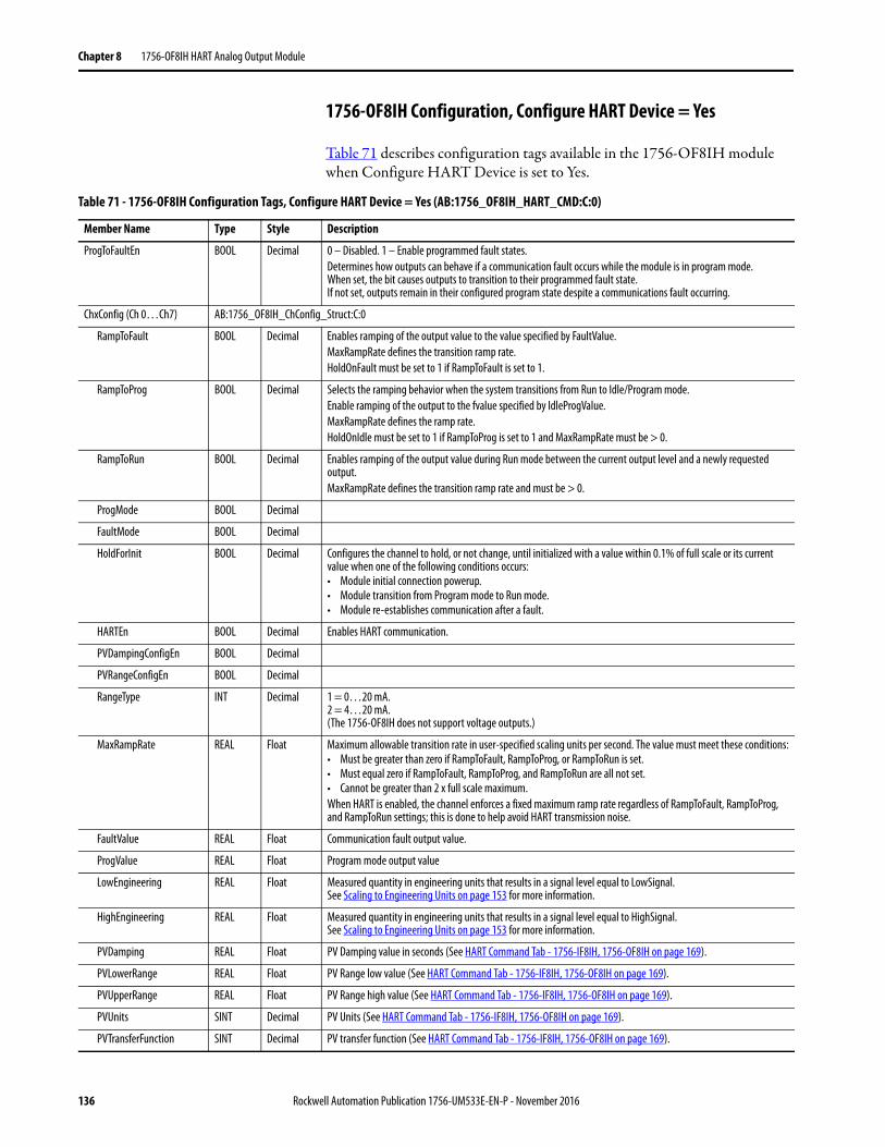
Chapter 8 1756-OF8IH HART Analog Output Module
1756-OF8IH Configuration, Configure HART Device = Yes
Table 71 describes configuration tags available in the 1756-OF8IH module when Configure HART Device is set to Yes.
Table 71 - 1756-OF8IH Configuration Tags, Configure HART Device = Yes (AB:1756_OF8IH_HART_CMD:C:0)
Member Name Type Style Description
ProgToFaultEn BOOL Decimal 0 – Disabled. 1 – Enable programmed fault states.Determines how outputs can behave if a communication fault occurs while the module is in program mode. When set, the bit causes outputs to transition to their programmed fault state.If not set, outputs remain in their configured program state despite a communications fault occurring.
ChxConfig (Ch 0…Ch7) AB:1756_OF8IH_ChConfig_Struct:C:0
RampToFault BOOL Decimal Enables ramping of the output value to the value specified by FaultValue.MaxRampRate defines the transition ramp rate.HoldOnFault must be set to 1 if RampToFault is set to 1.
RampToProg BOOL Decimal Selects the ramping behavior when the system transitions from Run to Idle/Program mode.Enable ramping of the output to the fvalue specified by IdleProgValue.MaxRampRate defines the ramp rate.HoldOnIdle must be set to 1 if RampToProg is set to 1 and MaxRampRate must be > 0.
RampToRun BOOL Decimal Enables ramping of the output value during Run mode between the current output level and a newly requested output.MaxRampRate defines the transition ramp rate and must be > 0.
ProgMode BOOL Decimal
FaultMode BOOL Decimal
HoldForInit BOOL Decimal Configures the channel to hold, or not change, until initialized with a value within 0.1% of full scale or its current value when one of the following conditions occurs:• Module initial connection powerup.• Module transition from Program mode to Run mode.• Module re-establishes communication after a fault.
HARTEn BOOL Decimal Enables HART communication.
PVDampingConfigEn BOOL Decimal
PVRangeConfigEn BOOL Decimal
RangeType INT Decimal 1 = 0…20 mA.2 = 4…20 mA.(The 1756-OF8IH does not support voltage outputs.)
MaxRampRate REAL Float Maximum allowable transition rate in user-specified scaling units per second. The value must meet these conditions:• Must be greater than zero if RampToFault, RampToProg, or RampToRun is set. • Must equal zero if RampToFault, RampToProg, and RampToRun are all not set.• Cannot be greater than 2 x full scale maximum.When HART is enabled, the channel enforces a fixed maximum ramp rate regardless of RampToFault, RampToProg, and RampToRun settings; this is done to help avoid HART transmission noise.
FaultValue REAL Float Communication fault output value.
ProgValue REAL Float Program mode output value
LowEngineering REAL Float Measured quantity in engineering units that results in a signal level equal to LowSignal. See Scaling to Engineering Units on page 153 for more information.
HighEngineering REAL Float Measured quantity in engineering units that results in a signal level equal to HighSignal. See Scaling to Engineering Units on page 153 for more information.
PVDamping REAL Float PV Damping value in seconds (See HART Command Tab - 1756-IF8IH, 1756-OF8IH on page 169).
PVLowerRange REAL Float PV Range low value (See HART Command Tab - 1756-IF8IH, 1756-OF8IH on page 169).
PVUpperRange REAL Float PV Range high value (See HART Command Tab - 1756-IF8IH, 1756-OF8IH on page 169).
PVUnits SINT Decimal PV Units (See HART Command Tab - 1756-IF8IH, 1756-OF8IH on page 169).
PVTransferFunction SINT Decimal PV transfer function (See HART Command Tab - 1756-IF8IH, 1756-OF8IH on page 169).
136 Rockwell Automation Publication 1756-UM533E-EN-P - November 2016
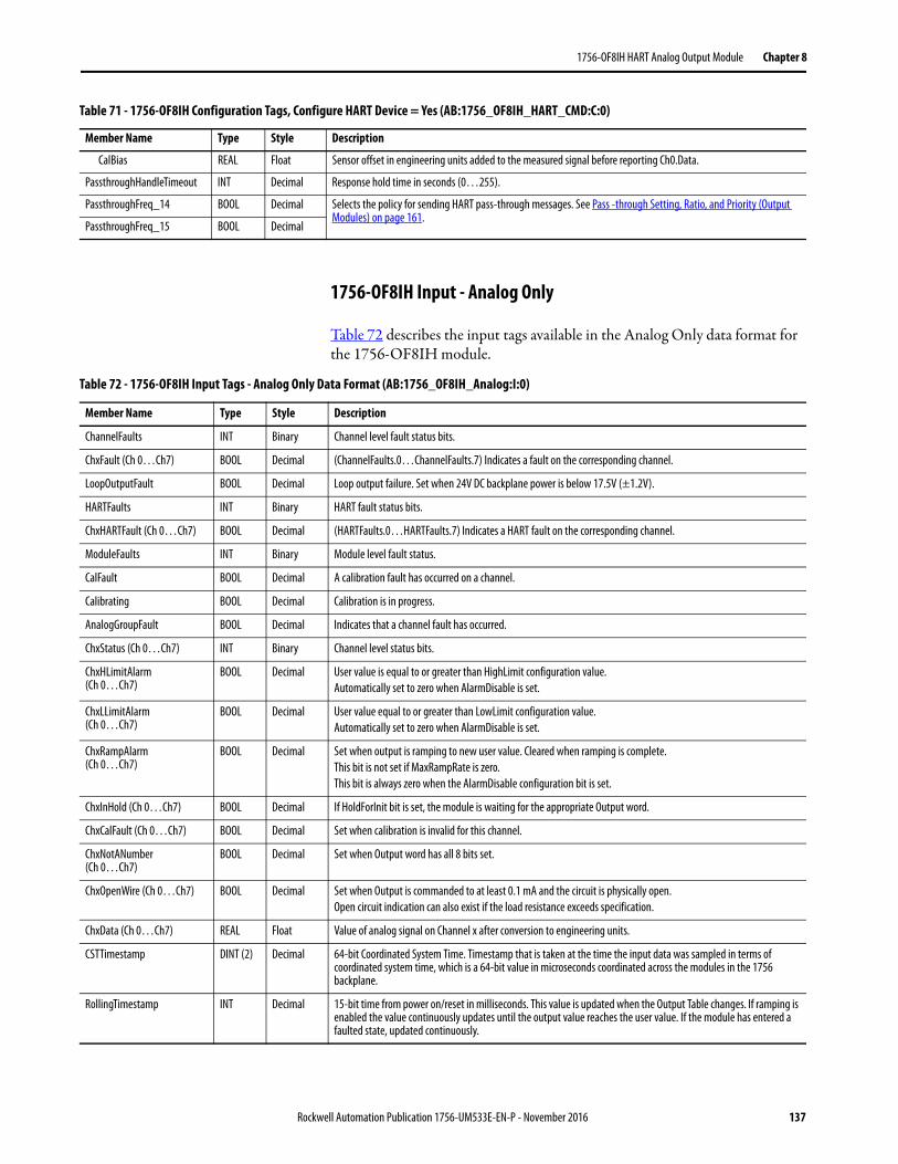
1756-OF8IH HART Analog Output Module Chapter 8
1756-OF8IH Input - Analog Only
Table 72 describes the input tags available in the Analog Only data format for the 1756-OF8IH module.
CalBias REAL Float Sensor offset in engineering units added to the measured signal before reporting Ch0.Data.
PassthroughHandleTimeout INT Decimal Response hold time in seconds (0…255).
PassthroughFreq_14 BOOL Decimal Selects the policy for sending HART pass-through messages. See Pass -through Setting, Ratio, and Priority (Output Modules) on page 161.
PassthroughFreq_15 BOOL Decimal
Table 71 - 1756-OF8IH Configuration Tags, Configure HART Device = Yes (AB:1756_OF8IH_HART_CMD:C:0)
Member Name Type Style Description
Table 72 - 1756-OF8IH Input Tags - Analog Only Data Format (AB:1756_OF8IH_Analog:I:0)
Member Name Type Style Description
ChannelFaults INT Binary Channel level fault status bits.
ChxFault (Ch 0…Ch7) BOOL Decimal (ChannelFaults.0…ChannelFaults.7) Indicates a fault on the corresponding channel.
LoopOutputFault BOOL Decimal Loop output failure. Set when 24V DC backplane power is below 17.5V (±1.2V).
HARTFaults INT Binary HART fault status bits.
ChxHARTFault (Ch 0…Ch7) BOOL Decimal (HARTFaults.0…HARTFaults.7) Indicates a HART fault on the corresponding channel.
ModuleFaults INT Binary Module level fault status.
CalFault BOOL Decimal A calibration fault has occurred on a channel.
Calibrating BOOL Decimal Calibration is in progress.
AnalogGroupFault BOOL Decimal Indicates that a channel fault has occurred.
ChxStatus (Ch 0…Ch7) INT Binary Channel level status bits.
ChxHLimitAlarm (Ch 0…Ch7)
BOOL Decimal User value is equal to or greater than HighLimit configuration value. Automatically set to zero when AlarmDisable is set.
ChxLLimitAlarm(Ch 0…Ch7)
BOOL Decimal User value equal to or greater than LowLimit configuration value.Automatically set to zero when AlarmDisable is set.
ChxRampAlarm(Ch 0…Ch7)
BOOL Decimal Set when output is ramping to new user value. Cleared when ramping is complete.This bit is not set if MaxRampRate is zero.This bit is always zero when the AlarmDisable configuration bit is set.
ChxInHold (Ch 0…Ch7) BOOL Decimal If HoldForInit bit is set, the module is waiting for the appropriate Output word.
ChxCalFault (Ch 0…Ch7) BOOL Decimal Set when calibration is invalid for this channel.
ChxNotANumber (Ch 0…Ch7)
BOOL Decimal Set when Output word has all 8 bits set.
ChxOpenWire (Ch 0…Ch7) BOOL Decimal Set when Output is commanded to at least 0.1 mA and the circuit is physically open.Open circuit indication can also exist if the load resistance exceeds specification.
ChxData (Ch 0…Ch7) REAL Float Value of analog signal on Channel x after conversion to engineering units.
CSTTimestamp DINT (2) Decimal 64-bit Coordinated System Time. Timestamp that is taken at the time the input data was sampled in terms of coordinated system time, which is a 64-bit value in microseconds coordinated across the modules in the 1756 backplane.
RollingTimestamp INT Decimal 15-bit time from power on/reset in milliseconds. This value is updated when the Output Table changes. If ramping is enabled the value continuously updates until the output value reaches the user value. If the module has entered a faulted state, updated continuously.
Rockwell Automation Publication 1756-UM533E-EN-P - November 2016 137
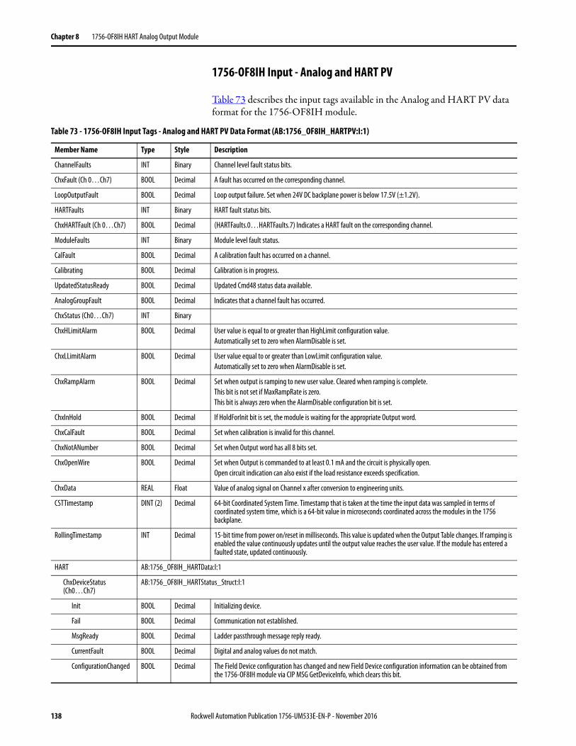
Chapter 8 1756-OF8IH HART Analog Output Module
1756-OF8IH Input - Analog and HART PV
Table 73 describes the input tags available in the Analog and HART PV data format for the 1756-OF8IH module.
Table 73 - 1756-OF8IH Input Tags - Analog and HART PV Data Format (AB:1756_OF8IH_HARTPV:I:1)
Member Name Type Style Description
ChannelFaults INT Binary Channel level fault status bits.
ChxFault (Ch 0…Ch7) BOOL Decimal A fault has occurred on the corresponding channel.
LoopOutputFault BOOL Decimal Loop output failure. Set when 24V DC backplane power is below 17.5V (±1.2V).
HARTFaults INT Binary HART fault status bits.
ChxHARTFault (Ch 0…Ch7) BOOL Decimal (HARTFaults.0…HARTFaults.7) Indicates a HART fault on the corresponding channel.
ModuleFaults INT Binary Module level fault status.
CalFault BOOL Decimal A calibration fault has occurred on a channel.
Calibrating BOOL Decimal Calibration is in progress.
UpdatedStatusReady BOOL Decimal Updated Cmd48 status data available.
AnalogGroupFault BOOL Decimal Indicates that a channel fault has occurred.
ChxStatus (Ch0…Ch7) INT Binary
ChxHLimitAlarm BOOL Decimal User value is equal to or greater than HighLimit configuration value. Automatically set to zero when AlarmDisable is set.
ChxLLimitAlarm BOOL Decimal User value equal to or greater than LowLimit configuration value.Automatically set to zero when AlarmDisable is set.
ChxRampAlarm BOOL Decimal Set when output is ramping to new user value. Cleared when ramping is complete.This bit is not set if MaxRampRate is zero.This bit is always zero when the AlarmDisable configuration bit is set.
ChxInHold BOOL Decimal If HoldForInit bit is set, the module is waiting for the appropriate Output word.
ChxCalFault BOOL Decimal Set when calibration is invalid for this channel.
ChxNotANumber BOOL Decimal Set when Output word has all 8 bits set.
ChxOpenWire BOOL Decimal Set when Output is commanded to at least 0.1 mA and the circuit is physically open.Open circuit indication can also exist if the load resistance exceeds specification.
ChxData REAL Float Value of analog signal on Channel x after conversion to engineering units.
CSTTimestamp DINT (2) Decimal 64-bit Coordinated System Time. Timestamp that is taken at the time the input data was sampled in terms of coordinated system time, which is a 64-bit value in microseconds coordinated across the modules in the 1756 backplane.
RollingTimestamp INT Decimal 15-bit time from power on/reset in milliseconds. This value is updated when the Output Table changes. If ramping is enabled the value continuously updates until the output value reaches the user value. If the module has entered a faulted state, updated continuously.
HART AB:1756_OF8IH_HARTData:I:1
ChxDeviceStatus(Ch0…Ch7)
AB:1756_OF8IH_HARTStatus_Struct:I:1
Init BOOL Decimal Initializing device.
Fail BOOL Decimal Communication not established.
MsgReady BOOL Decimal Ladder passthrough message reply ready.
CurrentFault BOOL Decimal Digital and analog values do not match.
ConfigurationChanged BOOL Decimal The Field Device configuration has changed and new Field Device configuration information can be obtained from the 1756-OF8IH module via CIP MSG GetDeviceInfo, which clears this bit.
138 Rockwell Automation Publication 1756-UM533E-EN-P - November 2016
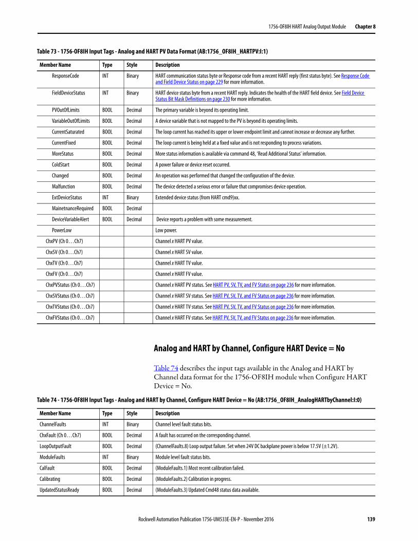
1756-OF8IH HART Analog Output Module Chapter 8
Analog and HART by Channel, Configure HART Device = No
Table 74 describes the input tags available in the Analog and HART by Channel data format for the 1756-OF8IH module when Configure HART Device = No.
ResponseCode INT Binary HART communication status byte or Response code from a recent HART reply (first status byte). See Response Code and Field Device Status on page 229 for more information.
FieldDeviceStatus INT Binary HART device status byte from a recent HART reply. Indicates the health of the HART field device. See Field Device Status Bit Mask Definitions on page 230 for more information.
PVOutOfLimits BOOL Decimal The primary variable is beyond its operating limit.
VariableOutOfLimits BOOL Decimal A device variable that is not mapped to the PV is beyond its operating limits.
CurrentSaturated BOOL Decimal The loop current has reached its upper or lower endpoint limit and cannot increase or decrease any further.
CurrentFixed BOOL Decimal The loop current is being held at a fixed value and is not responding to process variations.
MoreStatus BOOL Decimal More status information is available via command 48, ‘Read Additional Status’ information.
ColdStart BOOL Decimal A power failure or device reset occurred.
Changed BOOL Decimal An operation was performed that changed the configuration of the device.
Malfunction BOOL Decimal The device detected a serious error or failure that compromises device operation.
ExtDeviceStatus INT Binary Extended device status (from HART cmd9)xx.
MainetnanceRequired BOOL Decimal
DeviceVariableAlert BOOL Decimal Device reports a problem with some measurement.
PowerLow Low power.
ChxPV (Ch 0…Ch7) Channel x HART PV value.
ChxSV (Ch 0…Ch7) Channel x HART SV value.
ChxTV (Ch 0…Ch7) Channel x HART TV value.
ChxFV (Ch 0…Ch7) Channel x HART FV value.
ChxPVStatus (Ch 0…Ch7) Channel x HART PV status. See HART PV, SV, TV, and FV Status on page 236 for more information.
ChxSVStatus (Ch 0…Ch7) Channel x HART SV status. See HART PV, SV, TV, and FV Status on page 236 for more information.
ChxTVStatus (Ch 0…Ch7) Channel x HART TV status. See HART PV, SV, TV, and FV Status on page 236 for more information.
ChxFVStatus (Ch 0…Ch7) Channel x HART FV status. See HART PV, SV, TV, and FV Status on page 236 for more information.
Table 73 - 1756-OF8IH Input Tags - Analog and HART PV Data Format (AB:1756_OF8IH_HARTPV:I:1)
Member Name Type Style Description
Table 74 - 1756-OF8IH Input Tags - Analog and HART by Channel, Configure HART Device = No (AB:1756_OF8IH_AnalogHARTbyChannel:I:0)
Member Name Type Style Description
ChannelFaults INT Binary Channel level fault status bits.
ChxFault (Ch 0…Ch7) BOOL Decimal A fault has occurred on the corresponding channel.
LoopOutputFault BOOL Decimal (ChannelFaults.8) Loop output failure. Set when 24V DC backplane power is below 17.5V (±1.2V).
ModuleFaults INT Binary Module level fault status bits.
CalFault BOOL Decimal (ModuleFaults.1) Most recent calibration failed.
Calibrating BOOL Decimal (ModuleFaults.2) Calibration in progress.
UpdatedStatusReady BOOL Decimal (ModuleFaults.3) Updated Cmd48 status data available.
Rockwell Automation Publication 1756-UM533E-EN-P - November 2016 139
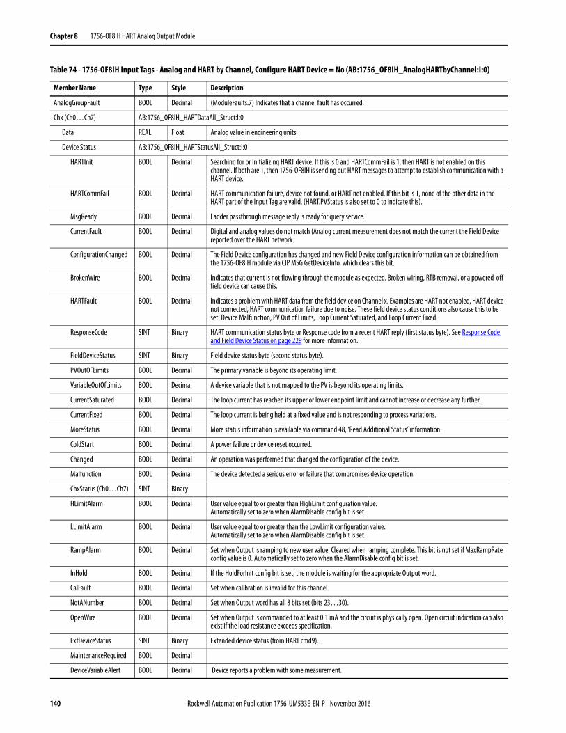
Chapter 8 1756-OF8IH HART Analog Output Module
AnalogGroupFault BOOL Decimal (ModuleFaults.7) Indicates that a channel fault has occurred.
Chx (Ch0…Ch7) AB:1756_OF8IH_HARTDataAll_Struct:I:0
Data REAL Float Analog value in engineering units.
Device Status AB:1756_OF8IH_HARTStatusAll_Struct:I:0
HARTInit BOOL Decimal Searching for or Initializing HART device. If this is 0 and HARTCommFail is 1, then HART is not enabled on this channel. If both are 1, then 1756-OF8IH is sending out HART messages to attempt to establish communication with a HART device.
HARTCommFail BOOL Decimal HART communication failure, device not found, or HART not enabled. If this bit is 1, none of the other data in the HART part of the Input Tag are valid. (HART.PVStatus is also set to 0 to indicate this).
MsgReady BOOL Decimal Ladder passthrough message reply is ready for query service.
CurrentFault BOOL Decimal Digital and analog values do not match (Analog current measurement does not match the current the Field Device reported over the HART network.
ConfigurationChanged BOOL Decimal The Field Device configuration has changed and new Field Device configuration information can be obtained from the 1756-OF8IH module via CIP MSG GetDeviceInfo, which clears this bit.
BrokenWire BOOL Decimal Indicates that current is not flowing through the module as expected. Broken wiring, RTB removal, or a powered-off field device can cause this.
HARTFault BOOL Decimal Indicates a problem with HART data from the field device on Channel x. Examples are HART not enabled, HART device not connected, HART communication failure due to noise. These field device status conditions also cause this to be set: Device Malfunction, PV Out of Limits, Loop Current Saturated, and Loop Current Fixed.
ResponseCode SINT Binary HART communication status byte or Response code from a recent HART reply (first status byte). See Response Code and Field Device Status on page 229 for more information.
FieldDeviceStatus SINT Binary Field device status byte (second status byte).
PVOutOFLimits BOOL Decimal The primary variable is beyond its operating limit.
VariableOutOfLimits BOOL Decimal A device variable that is not mapped to the PV is beyond its operating limits.
CurrentSaturated BOOL Decimal The loop current has reached its upper or lower endpoint limit and cannot increase or decrease any further.
CurrentFixed BOOL Decimal The loop current is being held at a fixed value and is not responding to process variations.
MoreStatus BOOL Decimal More status information is available via command 48, ‘Read Additional Status’ information.
ColdStart BOOL Decimal A power failure or device reset occurred.
Changed BOOL Decimal An operation was performed that changed the configuration of the device.
Malfunction BOOL Decimal The device detected a serious error or failure that compromises device operation.
ChxStatus (Ch0…Ch7) SINT Binary
HLimitAlarm BOOL Decimal User value equal to or greater than HighLimit configuration value. Automatically set to zero when AlarmDisable config bit is set.
LLimitAlarm BOOL Decimal User value equal to or greater than the LowLimit configuration value. Automatically set to zero when AlarmDisable config bit is set.
RampAlarm BOOL Decimal Set when Output is ramping to new user value. Cleared when ramping complete. This bit is not set if MaxRampRate config value is 0. Automatically set to zero when the AlarmDisable config bit is set.
InHold BOOL Decimal If the HoldForInit config bit is set, the module is waiting for the appropriate Output word.
CalFault BOOL Decimal Set when calibration is invalid for this channel.
NotANumber BOOL Decimal Set when Output word has all 8 bits set (bits 23…30).
OpenWire BOOL Decimal Set when Output is commanded to at least 0.1 mA and the circuit is physically open. Open circuit indication can also exist if the load resistance exceeds specification.
ExtDeviceStatus SINT Binary Extended device status (from HART cmd9).
MaintenanceRequired BOOL Decimal
DeviceVariableAlert BOOL Decimal Device reports a problem with some measurement.
Table 74 - 1756-OF8IH Input Tags - Analog and HART by Channel, Configure HART Device = No (AB:1756_OF8IH_AnalogHARTbyChannel:I:0)
Member Name Type Style Description
140 Rockwell Automation Publication 1756-UM533E-EN-P - November 2016
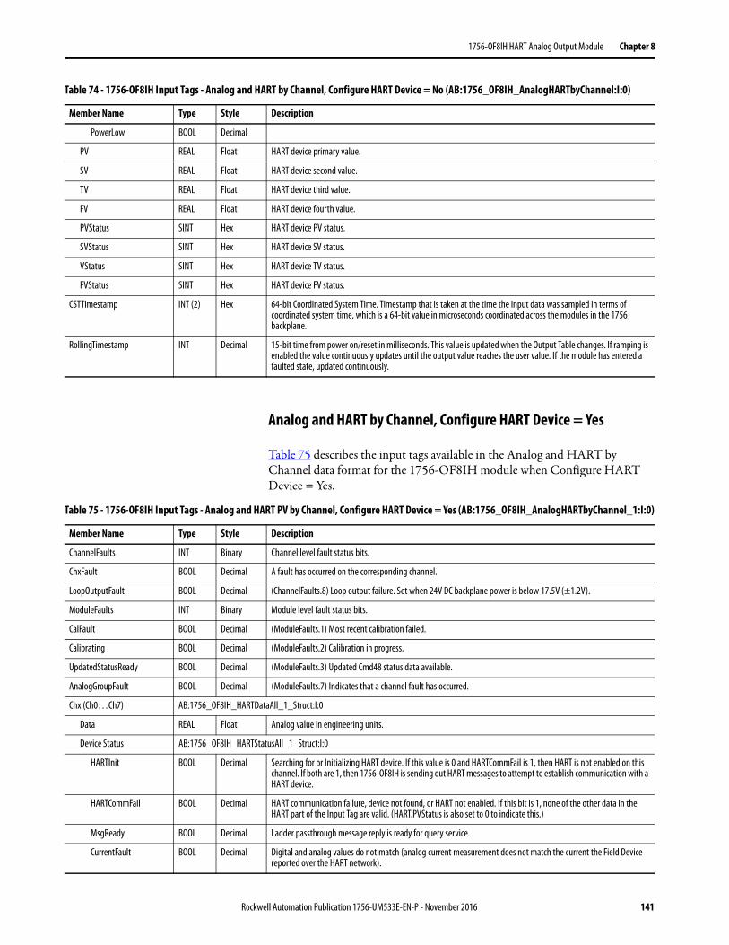
1756-OF8IH HART Analog Output Module Chapter 8
Analog and HART by Channel, Configure HART Device = Yes
Table 75 describes the input tags available in the Analog and HART by Channel data format for the 1756-OF8IH module when Configure HART Device = Yes.
PowerLow BOOL Decimal
PV REAL Float HART device primary value.
SV REAL Float HART device second value.
TV REAL Float HART device third value.
FV REAL Float HART device fourth value.
PVStatus SINT Hex HART device PV status.
SVStatus SINT Hex HART device SV status.
VStatus SINT Hex HART device TV status.
FVStatus SINT Hex HART device FV status.
CSTTimestamp INT (2) Hex 64-bit Coordinated System Time. Timestamp that is taken at the time the input data was sampled in terms of coordinated system time, which is a 64-bit value in microseconds coordinated across the modules in the 1756 backplane.
RollingTimestamp INT Decimal 15-bit time from power on/reset in milliseconds. This value is updated when the Output Table changes. If ramping is enabled the value continuously updates until the output value reaches the user value. If the module has entered a faulted state, updated continuously.
Table 74 - 1756-OF8IH Input Tags - Analog and HART by Channel, Configure HART Device = No (AB:1756_OF8IH_AnalogHARTbyChannel:I:0)
Member Name Type Style Description
Table 75 - 1756-OF8IH Input Tags - Analog and HART PV by Channel, Configure HART Device = Yes (AB:1756_OF8IH_AnalogHARTbyChannel_1:I:0)
Member Name Type Style Description
ChannelFaults INT Binary Channel level fault status bits.
ChxFault BOOL Decimal A fault has occurred on the corresponding channel.
LoopOutputFault BOOL Decimal (ChannelFaults.8) Loop output failure. Set when 24V DC backplane power is below 17.5V (±1.2V).
ModuleFaults INT Binary Module level fault status bits.
CalFault BOOL Decimal (ModuleFaults.1) Most recent calibration failed.
Calibrating BOOL Decimal (ModuleFaults.2) Calibration in progress.
UpdatedStatusReady BOOL Decimal (ModuleFaults.3) Updated Cmd48 status data available.
AnalogGroupFault BOOL Decimal (ModuleFaults.7) Indicates that a channel fault has occurred.
Chx (Ch0…Ch7) AB:1756_OF8IH_HARTDataAll_1_Struct:I:0
Data REAL Float Analog value in engineering units.
Device Status AB:1756_OF8IH_HARTStatusAll_1_Struct:I:0
HARTInit BOOL Decimal Searching for or Initializing HART device. If this value is 0 and HARTCommFail is 1, then HART is not enabled on this channel. If both are 1, then 1756-OF8IH is sending out HART messages to attempt to establish communication with a HART device.
HARTCommFail BOOL Decimal HART communication failure, device not found, or HART not enabled. If this bit is 1, none of the other data in the HART part of the Input Tag are valid. (HART.PVStatus is also set to 0 to indicate this.)
MsgReady BOOL Decimal Ladder passthrough message reply is ready for query service.
CurrentFault BOOL Decimal Digital and analog values do not match (analog current measurement does not match the current the Field Device reported over the HART network).
Rockwell Automation Publication 1756-UM533E-EN-P - November 2016 141
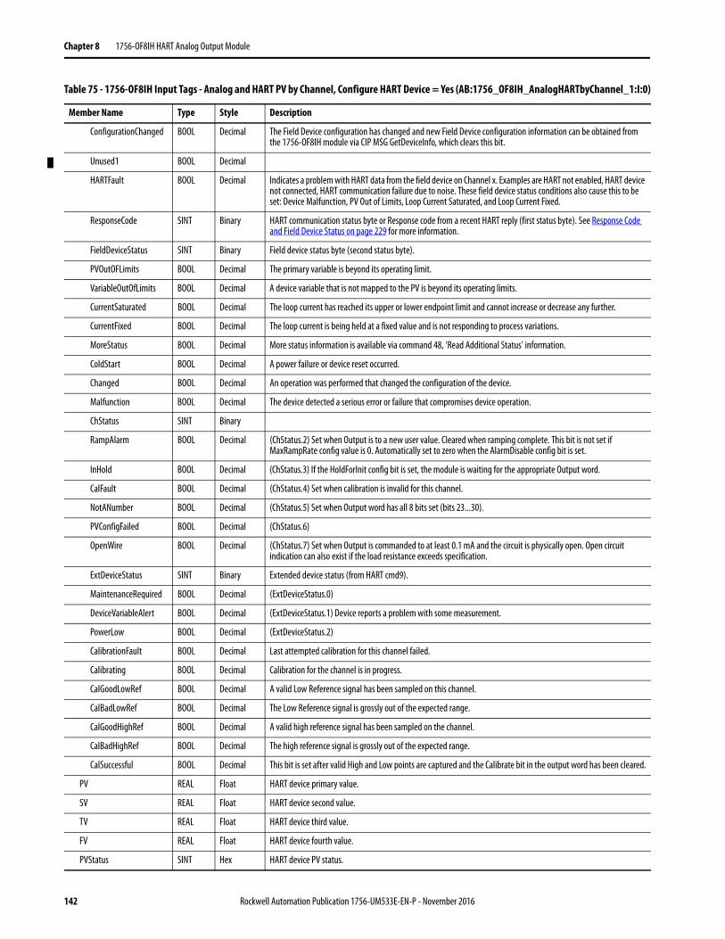
Chapter 8 1756-OF8IH HART Analog Output Module
ConfigurationChanged BOOL Decimal The Field Device configuration has changed and new Field Device configuration information can be obtained from the 1756-OF8IH module via CIP MSG GetDeviceInfo, which clears this bit.
Unused1 BOOL Decimal
HARTFault BOOL Decimal Indicates a problem with HART data from the field device on Channel x. Examples are HART not enabled, HART device not connected, HART communication failure due to noise. These field device status conditions also cause this to be set: Device Malfunction, PV Out of Limits, Loop Current Saturated, and Loop Current Fixed.
ResponseCode SINT Binary HART communication status byte or Response code from a recent HART reply (first status byte). See Response Code and Field Device Status on page 229 for more information.
FieldDeviceStatus SINT Binary Field device status byte (second status byte).
PVOutOFLimits BOOL Decimal The primary variable is beyond its operating limit.
VariableOutOfLimits BOOL Decimal A device variable that is not mapped to the PV is beyond its operating limits.
CurrentSaturated BOOL Decimal The loop current has reached its upper or lower endpoint limit and cannot increase or decrease any further.
CurrentFixed BOOL Decimal The loop current is being held at a fixed value and is not responding to process variations.
MoreStatus BOOL Decimal More status information is available via command 48, ‘Read Additional Status’ information.
ColdStart BOOL Decimal A power failure or device reset occurred.
Changed BOOL Decimal An operation was performed that changed the configuration of the device.
Malfunction BOOL Decimal The device detected a serious error or failure that compromises device operation.
ChStatus SINT Binary
RampAlarm BOOL Decimal (ChStatus.2) Set when Output is to a new user value. Cleared when ramping complete. This bit is not set if MaxRampRate config value is 0. Automatically set to zero when the AlarmDisable config bit is set.
InHold BOOL Decimal (ChStatus.3) If the HoldForInit config bit is set, the module is waiting for the appropriate Output word.
CalFault BOOL Decimal (ChStatus.4) Set when calibration is invalid for this channel.
NotANumber BOOL Decimal (ChStatus.5) Set when Output word has all 8 bits set (bits 23...30).
PVConfigFailed BOOL Decimal (ChStatus.6)
OpenWire BOOL Decimal (ChStatus.7) Set when Output is commanded to at least 0.1 mA and the circuit is physically open. Open circuit indication can also exist if the load resistance exceeds specification.
ExtDeviceStatus SINT Binary Extended device status (from HART cmd9).
MaintenanceRequired BOOL Decimal (ExtDeviceStatus.0)
DeviceVariableAlert BOOL Decimal (ExtDeviceStatus.1) Device reports a problem with some measurement.
PowerLow BOOL Decimal (ExtDeviceStatus.2)
CalibrationFault BOOL Decimal Last attempted calibration for this channel failed.
Calibrating BOOL Decimal Calibration for the channel is in progress.
CalGoodLowRef BOOL Decimal A valid Low Reference signal has been sampled on this channel.
CalBadLowRef BOOL Decimal The Low Reference signal is grossly out of the expected range.
CalGoodHighRef BOOL Decimal A valid high reference signal has been sampled on the channel.
CalBadHighRef BOOL Decimal The high reference signal is grossly out of the expected range.
CalSuccessful BOOL Decimal This bit is set after valid High and Low points are captured and the Calibrate bit in the output word has been cleared.
PV REAL Float HART device primary value.
SV REAL Float HART device second value.
TV REAL Float HART device third value.
FV REAL Float HART device fourth value.
PVStatus SINT Hex HART device PV status.
Table 75 - 1756-OF8IH Input Tags - Analog and HART PV by Channel, Configure HART Device = Yes (AB:1756_OF8IH_AnalogHARTbyChannel_1:I:0)
Member Name Type Style Description
142 Rockwell Automation Publication 1756-UM533E-EN-P - November 2016
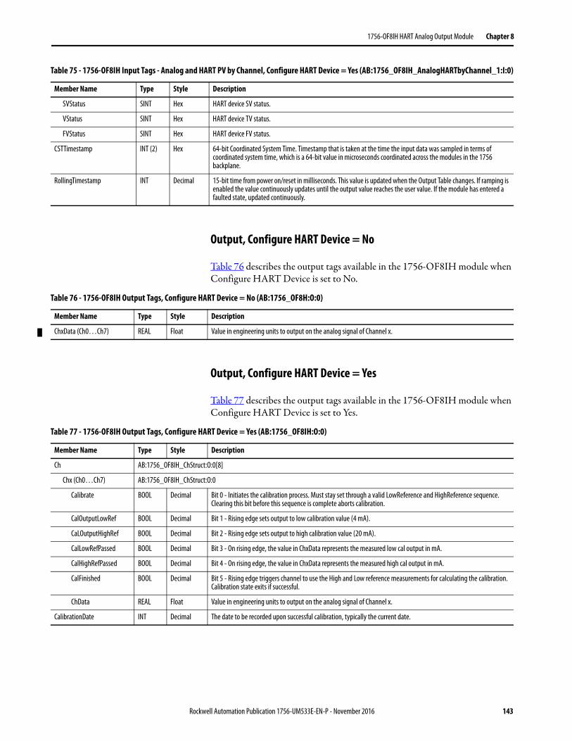
1756-OF8IH HART Analog Output Module Chapter 8
Output, Configure HART Device = No
Table 76 describes the output tags available in the 1756-OF8IH module when Configure HART Device is set to No.
Output, Configure HART Device = Yes
Table 77 describes the output tags available in the 1756-OF8IH module when Configure HART Device is set to Yes.
SVStatus SINT Hex HART device SV status.
VStatus SINT Hex HART device TV status.
FVStatus SINT Hex HART device FV status.
CSTTimestamp INT (2) Hex 64-bit Coordinated System Time. Timestamp that is taken at the time the input data was sampled in terms of coordinated system time, which is a 64-bit value in microseconds coordinated across the modules in the 1756 backplane.
RollingTimestamp INT Decimal 15-bit time from power on/reset in milliseconds. This value is updated when the Output Table changes. If ramping is enabled the value continuously updates until the output value reaches the user value. If the module has entered a faulted state, updated continuously.
Table 75 - 1756-OF8IH Input Tags - Analog and HART PV by Channel, Configure HART Device = Yes (AB:1756_OF8IH_AnalogHARTbyChannel_1:I:0)
Member Name Type Style Description
Table 76 - 1756-OF8IH Output Tags, Configure HART Device = No (AB:1756_OF8H:O:0)
Member Name Type Style Description
ChxData (Ch0…Ch7) REAL Float Value in engineering units to output on the analog signal of Channel x.
Table 77 - 1756-OF8IH Output Tags, Configure HART Device = Yes (AB:1756_OF8IH:O:0)
Member Name Type Style Description
Ch AB:1756_OF8IH_ChStruct:O:0[8]
Chx (Ch0…Ch7) AB:1756_OF8IH_ChStruct:O:0
Calibrate BOOL Decimal Bit 0 - Initiates the calibration process. Must stay set through a valid LowReference and HighReference sequence. Clearing this bit before this sequence is complete aborts calibration.
CalOutputLowRef BOOL Decimal Bit 1 - Rising edge sets output to low calibration value (4 mA).
CaLOutputHighRef BOOL Decimal Bit 2 - Rising edge sets output to high calibration value (20 mA).
CalLowRefPassed BOOL Decimal Bit 3 - On rising edge, the value in ChxData represents the measured low cal output in mA.
CalHighRefPassed BOOL Decimal Bit 4 - On rising edge, the value in ChxData represents the measured high cal output in mA.
CalFinished BOOL Decimal Bit 5 - Rising edge triggers channel to use the High and Low reference measurements for calculating the calibration. Calibration state exits if successful.
ChData REAL Float Value in engineering units to output on the analog signal of Channel x.
CalibrationDate INT Decimal The date to be recorded upon successful calibration, typically the current date.
Rockwell Automation Publication 1756-UM533E-EN-P - November 2016 143

Chapter 8 1756-OF8IH HART Analog Output Module
Notes:
144 Rockwell Automation Publication 1756-UM533E-EN-P - November 2016
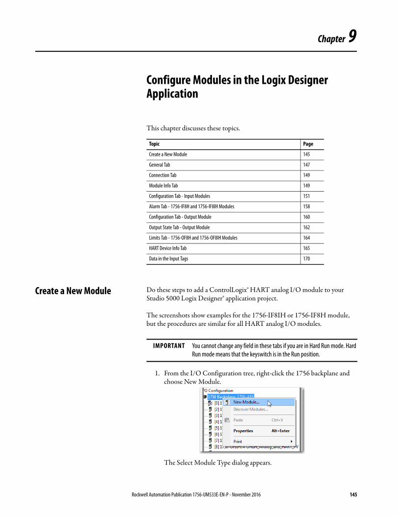
Chapter 9
Configure Modules in the Logix Designer Application
This chapter discusses these topics.
Create a New Module Do these steps to add a ControlLogix® HART analog I/O module to your Studio 5000 Logix Designer® application project.
The screenshots show examples for the 1756-IF8IH or 1756-IF8H module, but the procedures are similar for all HART analog I/O modules.
1. From the I/O Configuration tree, right-click the 1756 backplane and choose New Module.
The Select Module Type dialog appears.
Topic Page
Create a New Module 145
General Tab 147
Connection Tab 149
Module Info Tab 149
Configuration Tab - Input Modules 151
Alarm Tab - 1756-IF8H and 1756-IF8IH Modules 158
Configuration Tab - Output Module 160
Output State Tab - Output Module 162
Limits Tab - 1756-OF8H and 1756-OF8IH Modules 164
HART Device Info Tab 165
Data in the Input Tags 170
IMPORTANT You cannot change any field in these tabs if you are in Hard Run mode. Hard Run mode means that the keyswitch is in the Run position.
Rockwell Automation Publication 1756-UM533E-EN-P - November 2016 145
Chapter 9 Configure Modules in the Logix Designer Application
2. In the Select Module Type dialog, find and select the module that you want to add.
3. Click Create.
The New Module dialog box is displayed.
146 Rockwell Automation Publication 1756-UM533E-EN-P - November 2016
Configure Modules in the Logix Designer Application Chapter 9
General Tab Complete these instructions for general configuration.
1. On the General tab, do these steps:a. Type a name for the module.b. Optionally, type a description for the module.c. Select the slot number for the module.
2. In the Module Definition box, click Change.
The Module Definition dialog appears.
3. Complete these actions:
Parameter Action Values
Series Select the series letter that matches the label on the side of your module.
Pull-down menu
Revision Select the revision number that matches the label on the side of your module; make sure that the minor revision number also matches.
Pull-down menu
Electronic Keying Choose the electronic keying methodSee Electronic Keying on page 20 for more information
• Exact Match• Compatible Module (default)• Disable Keying
Connection Choose the connection type • Data - has more tabs on the Module Properties dialog box than Listen-only because of configuration settings for alarms, calibration
• Listen-only - has no configuration data, does not send output dataSee Listen-only Mode on page 30 for more information.
Input Data Choose the input data mode • Analog Only• Analog and HART PV• Analog and HART by ChannelSee HART Configuration for more information.
Configure HART Device Select whether to enable the Configure HART Device feature. This feature is available only for the 1756-IF8IH and 1756-OF8IH modules when data format is Analog and HART by Channel. If you select Yes, a HART Command tab is added to the configuration dialog, in which you specify configuration values to be sent to the HART device.
Values that can be added in the HART Command tab are PV Damping (seconds), PV Units, PV Upper Range, PV Lower Range, PV Transfer Function.
Coordinated System Time Not configurable Timestamped
Data Format Not configurable Float
Rockwell Automation Publication 1756-UM533E-EN-P - November 2016 147
Chapter 9 Configure Modules in the Logix Designer Application
HART Configuration
The Input Data selection that you make in the Module Definition dialog determines how HART field device data can be accessed. Access the Module Definition dialog from the General tab.
HART field device data is gathered through automatic collection of HART Field Device Process Variables and Health information. You can also access HART field device data with pass-through messages. See Use a CIP MSG to get HART Data on page 177 and HART Modules Used with Asset Management Software on page 199 for more information.
Table 78 shows which configuration options provide HART data in the input tag and which provide pass-through message access.
Even if you are not enabling HART on all channels, the Analog and HART PV input tag includes space for the data. However, this data space is marked with a HART Fault to indicate that the data is not valid. This feature lets you add HART instruments later without disturbing the tag layout.
Table 78 - HART Data Configuration Options
Input Data Format Enable HART Checkbox (Configuration Tab)
HART Data Input Tag Present? Pass-through Message Access for MSG or Asset Management
Analog only Not checked No No
Checked Yes
Analog and HART PV Not checked Fields present in tag, but data for this channel not valid
No
Checked Yes Yes
Analog and HART by Channel Not checked Fields present in tag, but data for this channel not valid
No
Checked Yes Yes
148 Rockwell Automation Publication 1756-UM533E-EN-P - November 2016
Configure Modules in the Logix Designer Application Chapter 9
Connection Tab Use the following information to make selections on the Connection tab.
Module Info Tab The Module Info tab displays module and status information. This tab is populated with data that comes directly from the module. The information on this window is displayed when the project is online.
Parameter Description
Requested Packet Interval Defines when the module multicasts its data onto the local chassis backplane.
Inhibit Module Prevents connection to the module. Use only if you do not want the module to be put into service.
Major Fault on Controller If Connection Fails While in Run Mode
The Logix controller performs a major fault if communication to this I/O module fails.
Use Unicast Connection over EtherNet/IP
Appears only for HART analog modules that use the Logix Designer application version 18 or later in a remote EtherNet/IP chassis.Use the default checkbox if there are no other controllers in ‘Listen-Only’ mode.Clear the box if there are other ‘listening’ controllers in the system.
Rockwell Automation Publication 1756-UM533E-EN-P - November 2016 149
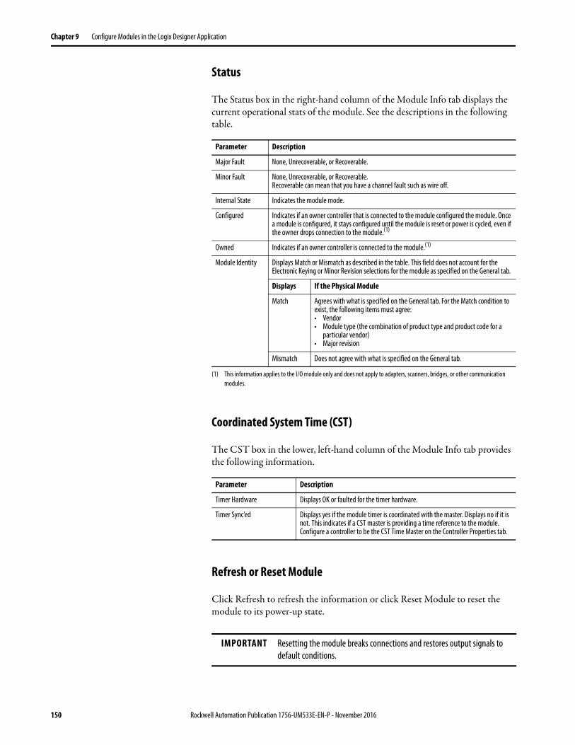
Chapter 9 Configure Modules in the Logix Designer Application
Status
The Status box in the right-hand column of the Module Info tab displays the current operational stats of the module. See the descriptions in the following table.
Coordinated System Time (CST)
The CST box in the lower, left-hand column of the Module Info tab provides the following information.
Refresh or Reset Module
Click Refresh to refresh the information or click Reset Module to reset the module to its power-up state.
Parameter Description
Major Fault None, Unrecoverable, or Recoverable.
Minor Fault None, Unrecoverable, or Recoverable. Recoverable can mean that you have a channel fault such as wire off.
Internal State Indicates the module mode.
Configured Indicates if an owner controller that is connected to the module configured the module. Once a module is configured, it stays configured until the module is reset or power is cycled, even if the owner drops connection to the module.(1)
(1) This information applies to the I/O module only and does not apply to adapters, scanners, bridges, or other communication modules.
Owned Indicates if an owner controller is connected to the module.(1)
Module Identity Displays Match or Mismatch as described in the table. This field does not account for the Electronic Keying or Minor Revision selections for the module as specified on the General tab.
Displays If the Physical Module
Match Agrees with what is specified on the General tab. For the Match condition to exist, the following items must agree: • Vendor• Module type (the combination of product type and product code for a
particular vendor)• Major revision
Mismatch Does not agree with what is specified on the General tab.
Parameter Description
Timer Hardware Displays OK or faulted for the timer hardware.
Timer Sync’ed Displays yes if the module timer is coordinated with the master. Displays no if it is not. This indicates if a CST master is providing a time reference to the module. Configure a controller to be the CST Time Master on the Controller Properties tab.
IMPORTANT Resetting the module breaks connections and restores output signals to default conditions.
150 Rockwell Automation Publication 1756-UM533E-EN-P - November 2016
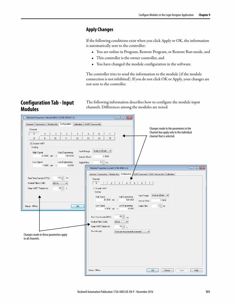
Configure Modules in the Logix Designer Application Chapter 9
Apply Changes
If the following conditions exist when you click Apply or OK, the information is automatically sent to the controller:
• You are online in Program, Remote Program, or Remote Run mode, and• This controller is the owner controller, and• You have changed the module configuration in the software.
The controller tries to send the information to the module (if the module connection is not inhibited). If you do not click OK or Apply, your changes are not sent to the controller.
Configuration Tab - Input Modules
The following information describes how to configure the module input channels. Differences among the modules are noted.
Changes made to the parameters in the Channel box apply only to the individual channel that is selected.
Changes made to these parameters apply to all channels.
Rockwell Automation Publication 1756-UM533E-EN-P - November 2016 151
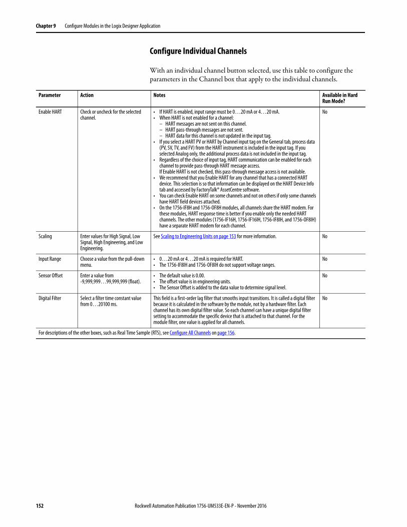
Chapter 9 Configure Modules in the Logix Designer Application
Configure Individual Channels
With an individual channel button selected, use this table to configure the parameters in the Channel box that apply to the individual channels.
Parameter Action Notes Available in Hard Run Mode?
Enable HART Check or uncheck for the selected channel.
• If HART is enabled, input range must be 0…20 mA or 4…20 mA. • When HART is not enabled for a channel:
– HART messages are not sent on this channel.– HART pass-through messages are not sent.– HART data for this channel is not updated in the input tag.
• If you select a HART PV or HART by Channel input tag on the General tab, process data (PV, SV, TV, and FV) from the HART instrument is included in the input tag. If you selected Analog only, the additional process data is not included in the input tag.
• Regardless of the choice of input tag, HART communication can be enabled for each channel to provide pass-through HART message access.If Enable HART is not checked, this pass-through message access is not available.
• We recommend that you Enable HART for any channel that has a connected HART device. This selection is so that information can be displayed on the HART Device Info tab and accessed by FactoryTalk® AssetCentre software.
• You can check Enable HART on some channels and not on others if only some channels have HART field devices attached.
• On the 1756-IF8H and 1756-OF8H modules, all channels share the HART modem. For these modules, HART response time is better if you enable only the needed HART channels. The other modules (1756-IF16H, 1756-IF16IH, 1756-IF8IH, and 1756-OF8IH) have a separate HART modem for each channel.
No
Scaling Enter values for High Signal, Low Signal, High Engineering, and Low Engineering.
See Scaling to Engineering Units on page 153 for more information. No
Input Range Choose a value from the pull-down menu.
• 0…20 mA or 4…20 mA is required for HART. • The 1756-IF8IH and 1756-OF8IH do not support voltage ranges.
No
Sensor Offset Enter a value from -9,999,999…99,999,999 (float).
• The default value is 0.00. • The offset value is in engineering units.• The Sensor Offset is added to the data value to determine signal level.
No
Digital Filter Select a filter time constant value from 0…20100 ms.
This field is a first-order lag filter that smooths input transitions. It is called a digital filter because it is calculated in the software by the module, not by a hardware filter. Each channel has its own digital filter value. So each channel can have a unique digital filter setting to accommodate the specific device that is attached to that channel. For the module filter, one value is applied for all channels.
No
For descriptions of the other boxes, such as Real Time Sample (RTS), see Configure All Channels on page 156.
152 Rockwell Automation Publication 1756-UM533E-EN-P - November 2016
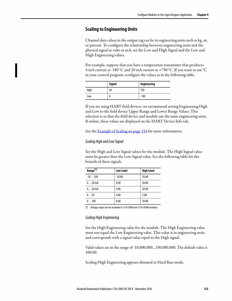
Configure Modules in the Logix Designer Application Chapter 9
Scaling to Engineering Units
Channel data values in the output tag can be in engineering units such as kg, m, or percent. To configure the relationship between engineering units and the physical signal in volts or mA, set the Low and High Signal and the Low and High Engineering values.
For example, suppose that you have a temperature transmitter that produces 4 mA current at -180 °C and 20 mA current at +750 °C. If you want to use °C in your control program, configure the values as in the following table.
If you are using HART field devices, we recommend setting Engineering High and Low to the field device Upper Range and Lower Range Values. This selection is so that the field device and module use the same engineering units. If online, these values are displayed on the HART Device Info tab.
See the Example of Scaling on page 154 for more information.
Scaling High and Low Signal
Set the High and Low Signal values for the module. The High Signal value must be greater than the Low Signal value. See the following table for the bounds of these signals.
Scaling High Engineering
Set the High Engineering value for the module. The High Engineering value must not equal the Low Engineering value. This value is in engineering units and corresponds with a signal value equal to the High signal.
Valid values are in the range of -10,000,000…100,000,000. The default value is 100.00.
Scaling High Engineering appears dimmed in Hard Run mode.
Signal Engineering
High 20 750
Low 4 -180
Range(1)
(1) Voltage ranges are not available in 1756-IF8IH and 1756-OF8IH modules.
Low Limit High Limit
-10…10V -10.00 10.00
0…20 mA 0.00 20.00
4…20 mA 4.00 20.00
0…5V 0.00 5.00
0…10V 0.00 10.00
Rockwell Automation Publication 1756-UM533E-EN-P - November 2016 153
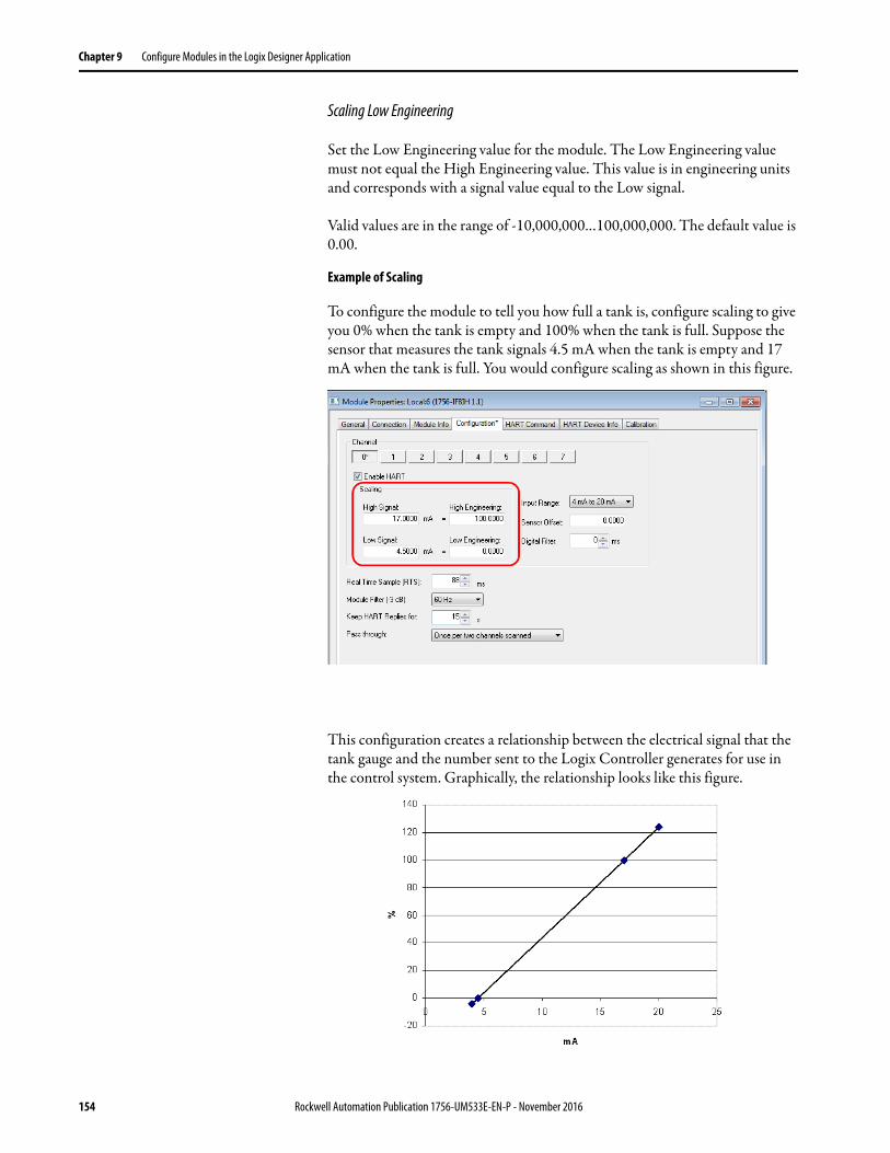
Chapter 9 Configure Modules in the Logix Designer Application
Scaling Low Engineering
Set the Low Engineering value for the module. The Low Engineering value must not equal the High Engineering value. This value is in engineering units and corresponds with a signal value equal to the Low signal.
Valid values are in the range of -10,000,000…100,000,000. The default value is 0.00.
Example of Scaling
To configure the module to tell you how full a tank is, configure scaling to give you 0% when the tank is empty and 100% when the tank is full. Suppose the sensor that measures the tank signals 4.5 mA when the tank is empty and 17 mA when the tank is full. You would configure scaling as shown in this figure.
This configuration creates a relationship between the electrical signal that the tank gauge and the number sent to the Logix Controller generates for use in the control system. Graphically, the relationship looks like this figure.
154 Rockwell Automation Publication 1756-UM533E-EN-P - November 2016
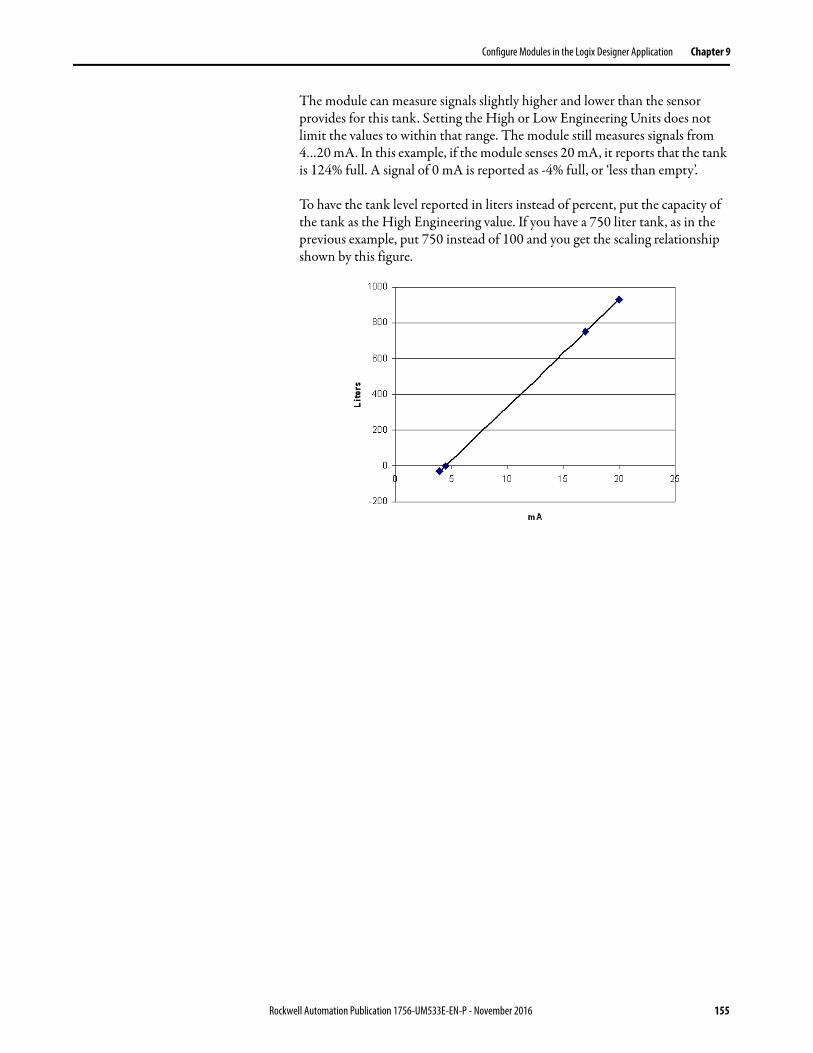
Configure Modules in the Logix Designer Application Chapter 9
The module can measure signals slightly higher and lower than the sensor provides for this tank. Setting the High or Low Engineering Units does not limit the values to within that range. The module still measures signals from 4…20 mA. In this example, if the module senses 20 mA, it reports that the tank is 124% full. A signal of 0 mA is reported as -4% full, or ‘less than empty’.
To have the tank level reported in liters instead of percent, put the capacity of the tank as the High Engineering value. If you have a 750 liter tank, as in the previous example, put 750 instead of 100 and you get the scaling relationship shown by this figure.
Rockwell Automation Publication 1756-UM533E-EN-P - November 2016 155
Chapter 9 Configure Modules in the Logix Designer Application
Configure All Channels
Use this table to configure the parameters on the Configuration tab that apply to all channels.
Parameter Action Notes Available in Hard Run Mode?
Real Time Sample (RTS) Choose a value from 0…10,000 ms.
• Determines the interval of time at which updated information is supplied to the controller.• The default is 88.• See Real Time Sample (RTS) on page 23 for more information.• See the Real-Time Sample Values table on page 156 for RTS choices available for each Module
Filter setting.
No
Module Filter (-3 dB) Choose a value from the pull-down menu.
• Because the digital HART communication signals are in the 1200…2400 Hz range, the module filter cannot be set to 1000 Hz if HART is enabled.
• See the Module Filter Values table on page 158 to choose a value.• See Module Filter on page 35 (1756-IF8H) or page 56 (1756-IF8IH) for more information.
No
Keep HART Replies Choose a value from 1…255 s.
• HART replies that are received from the Field Device in response to pass-through messages that have been sent are kept for this long. Retrieve them within this time or the module discards them.
• The default is 15.
• See Use a CIP MSG to get HART Data on page 177 for more information.
No
Pass through Choose a value from the pull-down menu.
• Determines how often pass-through messages occur.– Once per two channels scanned (default)- After two channels have PVs scanned to the input
tag, a pass-through message is sent (if one is pending).– Once per module scan - Choose this value if you want to minimize the impact pass-through
message clients have on reading the PVs into the input tag.– Once per channel scan - After each channel has its PVs scanned to the input tag, a pass-
through message is sent (if one is pending). Choose this value if you want to give pass-through messages from clients, such as FactoryTalk AssetCentre, higher priority than reading PV, SV, TV, FV, and field device health into the input tag. See the Pass-through Setting, Ratio, and Priority (Input Modules) table on page 156 for more information.
No
IMPORTANT We do not recommend a value of less than 15 s.
Table 79 - Real-Time Sample Values
Module Filter, Hz Low Limit, ms High Limit, ms
10 488 10000
15 328
20 248
50 88
60 88
100 (default) 56
250 28
1000 18
Table 80 - Pass-through Setting, Ratio, and Priority (Input Modules)
Setting Scan: Pass-through Ratio Gives Priority to
Once per channel scan 1:1 Asset management
Once per two channels scanned 1:2 Default setting
Once per module scan 1:8 Input tag scan
156 Rockwell Automation Publication 1756-UM533E-EN-P - November 2016
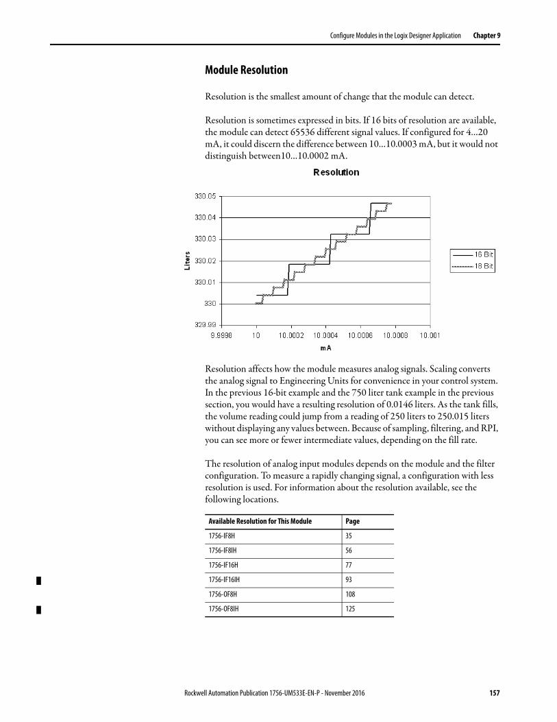
Configure Modules in the Logix Designer Application Chapter 9
Module Resolution
Resolution is the smallest amount of change that the module can detect.
Resolution is sometimes expressed in bits. If 16 bits of resolution are available, the module can detect 65536 different signal values. If configured for 4…20 mA, it could discern the difference between 10…10.0003 mA, but it would not distinguish between10…10.0002 mA.
Resolution affects how the module measures analog signals. Scaling converts the analog signal to Engineering Units for convenience in your control system. In the previous 16-bit example and the 750 liter tank example in the previous section, you would have a resulting resolution of 0.0146 liters. As the tank fills, the volume reading could jump from a reading of 250 liters to 250.015 liters without displaying any values between. Because of sampling, filtering, and RPI, you can see more or fewer intermediate values, depending on the fill rate.
The resolution of analog input modules depends on the module and the filter configuration. To measure a rapidly changing signal, a configuration with less resolution is used. For information about the resolution available, see the following locations.
Available Resolution for This Module Page
1756-IF8H 35
1756-IF8IH 56
1756-IF16H 77
1756-IF16IH 93
1756-OF8H 108
1756-OF8IH 125
Rockwell Automation Publication 1756-UM533E-EN-P - November 2016 157
Chapter 9 Configure Modules in the Logix Designer Application
Alarm Tab - 1756-IF8H and 1756-IF8IH Modules
The following information describes how to configure the parameters on the Alarm tab for the 1756-IF8H and 1756-IF8IH modules. For more information, see Process Alarms on page 38 or page 60, and Rate Alarm on page 39 or page 59.
IMPORTANT Because these modules must provide for possible calibration inaccuracies, resolution values represent the available analog-to-digital or digital-to-analog counts over the selected range, including a small amount of Overrange and Underrange.
Table 81 - Module Filter Values
Module Filter, Hz C.ModuleFilter
10(1)
(1) 10 Hz not supported in the 1756-IF16H or 1756-IF16IH modules.
0
15 7
20 6
50 1
60 (default) 2
100 3
250 4
1000(2)
(2) Do not choose 1000 with HART enabled.
5
158 Rockwell Automation Publication 1756-UM533E-EN-P - November 2016
Configure Modules in the Logix Designer Application Chapter 9
With an individual channel button selected, use these parameter descriptions to configure the alarms.
Table 82 - Alarm Tab Parameters
Parameter Action Notes Available in Hard Run Mode?
Process Alarms Enter values or drag the corresponding flags on the slider bar to set the values.
• The High Engineering and Low Engineering parameters on the Configuration tab set the maximum and minimum values for these alarms.
• Alarm thresholds are in engineering units.• To change the trigger points by whole numbers only, hold down the shift key while dragging the
flag on the slider bar.• A deadband appears around each value.
No
High High (HH) • Sets the level of input to a channel that causes the module to set the High High alarm.• The alarm remains active until the input returns below this level by more than the deadband.• If Latch Process Alarms is checked, the ChXHHAlarm indication remains set until explicitly cleared.
High (HI) • Sets the level of input to a channel that causes the module to set the High alarm.• The alarm remains until the input returns below this level by more than the deadband.• If Latch Process Alarms is checked, the ChXLAlarm indication remains set until explicitly cleared.
Low (LO) • Sets the level of input on a channel that causes the module to set the Low alarm.• The alarm remains until the input returns above this level by more than the deadband.• If Latch Process Alarms is checked, the ChXLAlarm indication remains set until explicitly cleared.
Low Low (LL) • Set the level of input to a channel that causes the module to set a Low Low alarm. • The alarm remains until the input returns above this level, more than the deadband. • If Latch Process Alarms is checked, the ChXLLAlarm indication remains set until explicitly cleared.
Disable All Alarms Check Disables all alarms for a channel. No
Latch Process Alarms Check Maintains an alarm triggered condition for any of the process alarms, even after the condition ceases. The alarm unlatches only with an explicit message that acknowledges the alarm.
No
Latch Rate Alarm Check When enabled, a Rate Alarm indication remains set, even when the alarm condition returns to normal. This latch lets you maintain the alarm even after the condition ceases. The alarm unlatches only with an explicit message that acknowledges the alarm.
No
Deadband Enter a value from 0.00…99,999,999.
• Select a value at which an alarm, once set, does not disable as long as the input value remains within the deadband range of the alarm trigger point. (This value in combination with the process alarms creates the range.) This configuration prevents the alarm from cycling on and off if the process value hovers near the alarm threshold.
• The alarm deadband can be only half the distance between high and low alarm limits.• The default is 0.00• For related information, see Alarm Deadband on page 38.
No
Rate Alarm Enter an alarm limit value from 0.00…99,999,999.
• Enter a Maximum Ramp Rate value to trigger a Rate Alarm when the input signal rate of change exceeds the setpoint.
• This configuraiton is useful for detecting rapid process changes.• The default is 0.00• Set this alarm in engineering units/second.
No
Unlatch All Click • Unlatches all alarms.• Is not available when the project is offline.
Yes
Unlatch Click • Unlatches the adjacent alarm condition.• Is not available when the project is offline.
Yes
Rockwell Automation Publication 1756-UM533E-EN-P - November 2016 159
Chapter 9 Configure Modules in the Logix Designer Application
Configuration Tab - Output Module
The following information describes how to configure the output channels of the module.
Configure Individual Channels
With an individual channel button selected, use this table to configure the parameters in the Channel box that apply to the individual channels.
Changes made to the parameters in the Channel box only apply to the individual channel that is selected.
Changes made to these parameters apply to all channels.
Table 83 - Configuration Tab Parameters
Parameter Action Notes Available in Hard Run Mode?
Enable HART Check or uncheck. • Unchecked by default.• Output range must be 0…20 mA or 4…20 mA.• When a channel is not enabled:
– HART messages are not sent on this channel.– HART pass-through messages are not sent.– HART data for this channel is not updated in the input tag.
• If you selected a HART PV or HART by Channel input tag input tag on the General tab, process data (PV, SV, TV, and FV) from the HART instrument is included in the input tag. If you selected Analog only, the process data is not included in the input tag.
• Regardless of the choice of input tag, HART communication can be enabled for each channel to provide pass-through HART message access. If Enable HART is not checked, this pass-through message access is not available.
• We recommend you Enable HART for any channel that has a HART device connected so that information can be displayed on the HART Device Info tab.
• One reason to disable HART communication is that each channel that is enabled requires time to scan, so enabling unnecessary channels reduces performance on the others.
No
Scaling Enter scaling values for High Signal, Low Signal, High Engineering, and Low Engineering.
See Scaling to Engineering Units on page 153 for more information. No
160 Rockwell Automation Publication 1756-UM533E-EN-P - November 2016
Configure Modules in the Logix Designer Application Chapter 9
Configure All Channels
Use Table 84 to configure the parameters on the Configuration tab that apply to all channels.
Output Range Chose a value from thepull-down menu.
0…20 mA or 4…20 mA is required for HART. No
Sensor Offset Enter a value from -9,999,999…99,999,999 (float).
• The default value is 0.00.• The offset value is in engineering units.• The Sensor Offset is added to the data value to determine signal level.
No
Hold for Initialization
Check or uncheck • Check this box to cause the module to hold the output signal unchanged until the output value received from the controller in the ChxData field is within 0.1% of full scale of the value being held. The output holds when the following occurs:– Powerup occurs (holds at zero)– A new connection is established (brings it out of fault state and it holds at the fault
value from the previous configuration).– The controller returns to Run mode after Program mode (continues to hold at the
configured value that was held in Program mode, see the Output State tab).• The output channel holding lets the controller synchronize with the output, enables
smooth output transitions and avoids rapid transients when control resumes from an interruption.
• The output can be ramping to the configured hold value when the transition occurs. In this case, it continues the ramp until it completes or until the output value from the controller is within the 0.1% of the output signal. When the Hold for Initialization box is not checked, the output switches as quickly as possible to the first value commanded by the controller.
No
Table 83 - Configuration Tab Parameters
Parameter Action Notes Available in Hard Run Mode?
Table 84 - All Channels Configuration Parameters
Parameter Action Notes Available in Hard Run Mode?
Keep HART Replies
Select a value from 1…255 s.
• HART pass-through message replies are kept for this time. HART replies that are received from the Field Device in response to pass-through messages you have sent are kept for this long. You must retrieve them within this time or the module discards them.
• The default is 15.
No
Pass through Choose a value from the pull-down menu.
• Determines how often pass-through messages occur.– Once per two channels scanned (default)- After 2 channels have PVs scanned to the input tag, a pass-
through message is sent (if one is pending).– Once per module scan - Choose this value if you want to minimize the impact pass-through message
clients have on reading the PVs into the input tag.– Once per channel scan - After each channel has its PVs scanned to input tag, a pass-through message
is sent (if one is pending). Choose this value if you want to give pass-through messages from clients such as FactoryTalk AssetCentre higher priority than reading PV, SV, TV, FV, and field device health into the input tag. See the Pass -through Setting, Ratio, and Priority (Output Modules) table on page 161 for more information.
No
IMPORTANT We do not recommend a value of less than 15 s.
Table 85 - Pass -through Setting, Ratio, and Priority (Output Modules)
Setting Scan:Pass-through ratio Gives priority to
Once per channel scan 1:1 Asset management
Once per two channels scanned 1:2 Default setting
Once per module scan 1:8 Input tag scan
Rockwell Automation Publication 1756-UM533E-EN-P - November 2016 161
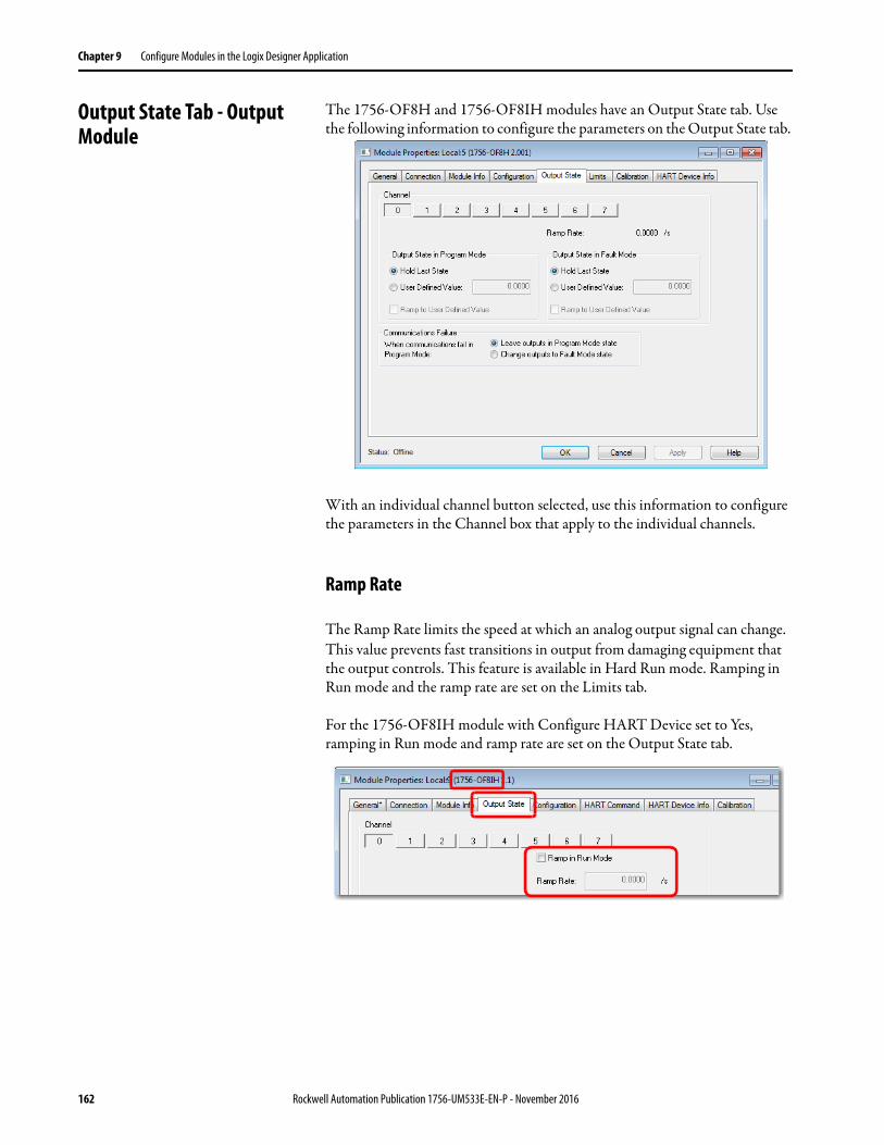
Chapter 9 Configure Modules in the Logix Designer Application
Output State Tab - Output Module
The 1756-OF8H and 1756-OF8IH modules have an Output State tab. Use the following information to configure the parameters on the Output State tab.
With an individual channel button selected, use this information to configure the parameters in the Channel box that apply to the individual channels.
Ramp Rate
The Ramp Rate limits the speed at which an analog output signal can change. This value prevents fast transitions in output from damaging equipment that the output controls. This feature is available in Hard Run mode. Ramping in Run mode and the ramp rate are set on the Limits tab.
For the 1756-OF8IH module with Configure HART Device set to Yes, ramping in Run mode and ramp rate are set on the Output State tab.
162 Rockwell Automation Publication 1756-UM533E-EN-P - November 2016
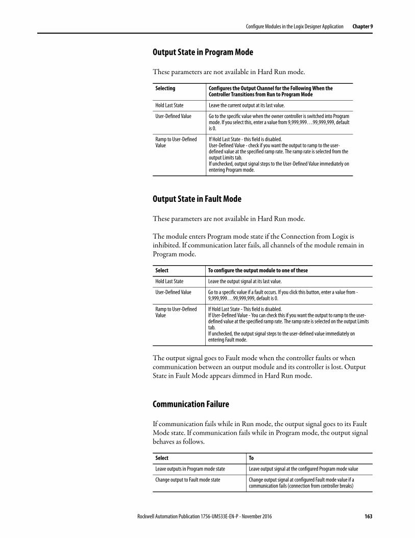
Configure Modules in the Logix Designer Application Chapter 9
Output State in Program Mode
These parameters are not available in Hard Run mode.
Output State in Fault Mode
These parameters are not available in Hard Run mode.
The module enters Program mode state if the Connection from Logix is inhibited. If communication later fails, all channels of the module remain in Program mode.
The output signal goes to Fault mode when the controller faults or when communication between an output module and its controller is lost. Output State in Fault Mode appears dimmed in Hard Run mode.
Communication Failure
If communication fails while in Run mode, the output signal goes to its Fault Mode state. If communication fails while in Program mode, the output signal behaves as follows.
Selecting Configures the Output Channel for the Following When the Controller Transitions from Run to Program Mode
Hold Last State Leave the current output at its last value.
User-Defined Value Go to the specific value when the owner controller is switched into Program mode. If you select this, enter a value from 9,999,999…99,999,999, default is 0.
Ramp to User-Defined Value
If Hold Last State - this field is disabled.User-Defined Value - check if you want the output to ramp to the user-defined value at the specified ramp rate. The ramp rate is selected from the output Limits tab.If unchecked, output signal steps to the User-Defined Value immediately on entering Program mode.
Select To configure the output module to one of these
Hold Last State Leave the output signal at its last value.
User-Defined Value Go to a specific value if a fault occurs. If you click this button, enter a value from -9,999,999…99,999,999, default is 0.
Ramp to User-Defined Value
If Hold Last State - This field is disabled.If User-Defined Value - You can check this if you want the output to ramp to the user-defined value at the specified ramp rate. The ramp rate is selected on the output Limits tab.If unchecked, the output signal steps to the user-defined value immediately on entering Fault mode.
Select To
Leave outputs in Program mode state Leave output signal at the configured Program mode value
Change output to Fault mode state Change output signal at configured Fault mode value if a communication fails (connection from controller breaks)
Rockwell Automation Publication 1756-UM533E-EN-P - November 2016 163
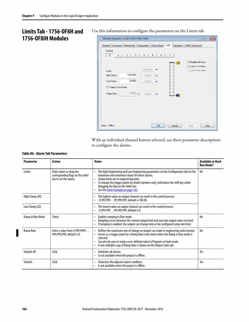
Chapter 9 Configure Modules in the Logix Designer Application
Limits Tab - 1756-OF8H and 1756-OF8IH Modules
Use this information to configure the parameters on the Limits tab.
With an individual channel button selected, use these parameter descriptions to configure the alarms.
Table 86 - Alarm Tab Parameters
Parameter Action Notes Available in Hard Run Mode?
Limits Enter values or drag the corresponding flags on the slider bar to set the values.
• The High Engineering and Low Engineering parameters on the Configuration tab set the maximum and minimum values for these alarms.
• Clamp limits are in engineering units.• To change the trigger points by whole numbers only, hold down the shift key while
dragging the flag on the slider bar.• See the Limit Example on page 165.
No
High Clamp (HI) • The highest value an output channel can reach in the control process.• -9,999,999…99,999,999, default is 100.00.
Low Clamp (LO) • The lowest value an output channel can reach in the control process.• -9,999,999…99,999,999, default is 0.
Ramp in Run Mode Check • Enables ramping in Run mode.• Ramping occurs between the current output level and any new output value received.• If ramping is enabled, the output can change only at the configured ramp rate limit.
No
Ramp Rate Enter a value from 9,999,9999… 999,999,999, default is 0.
• Defines the maximum rate of change an output can make in engineering units/second.• Serves as a trigger point for a Ramp Rate Limit alarm when the Ramp in Run mode is
selected.• Can also be uses to ramp a user-defined value in Program or Fault mode.• A non-editable copy of Ramp Rate is shown on the Output State tab.
No
Unlatch All Click • Unlatches all alarms.• Is not available when the project is offline.
Yes
Unlatch Click • Unlatches the adjacent alarm condition.• Is not available when the project is offline.
Yes
164 Rockwell Automation Publication 1756-UM533E-EN-P - November 2016
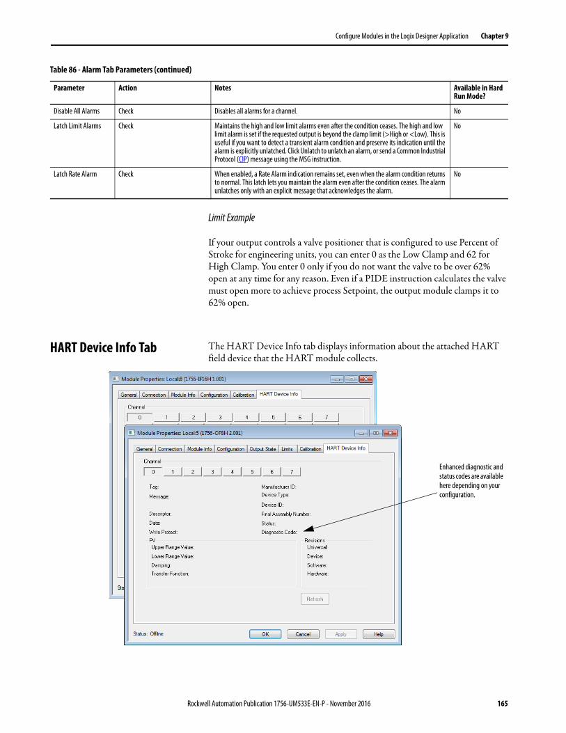
Configure Modules in the Logix Designer Application Chapter 9
Limit Example
If your output controls a valve positioner that is configured to use Percent of Stroke for engineering units, you can enter 0 as the Low Clamp and 62 for High Clamp. You enter 0 only if you do not want the valve to be over 62% open at any time for any reason. Even if a PIDE instruction calculates the valve must open more to achieve process Setpoint, the output module clamps it to 62% open.
HART Device Info Tab The HART Device Info tab displays information about the attached HART field device that the HART module collects.
Disable All Alarms Check Disables all alarms for a channel. No
Latch Limit Alarms Check Maintains the high and low limit alarms even after the condition ceases. The high and low limit alarm is set if the requested output is beyond the clamp limit (>High or <Low). This is useful if you want to detect a transient alarm condition and preserve its indication until the alarm is explicitly unlatched. Click Unlatch to unlatch an alarm, or send a Common Industrial Protocol (CIP) message using the MSG instruction.
No
Latch Rate Alarm Check When enabled, a Rate Alarm indication remains set, even when the alarm condition returns to normal. This latch lets you maintain the alarm even after the condition ceases. The alarm unlatches only with an explicit message that acknowledges the alarm.
No
Table 86 - Alarm Tab Parameters (continued)
Parameter Action Notes Available in Hard Run Mode?
Enhanced diagnostic and status codes are available here depending on your configuration.
Rockwell Automation Publication 1756-UM533E-EN-P - November 2016 165
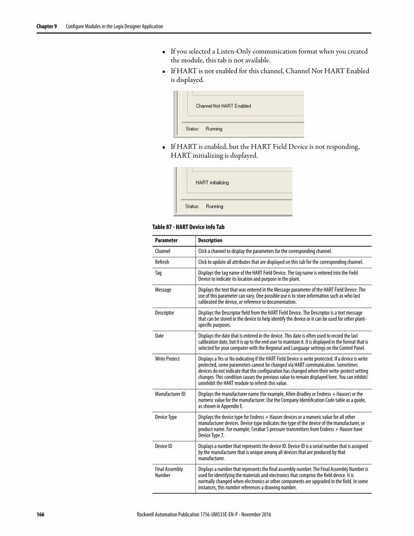
Chapter 9 Configure Modules in the Logix Designer Application
• If you selected a Listen-Only communication format when you created the module, this tab is not available.
• If HART is not enabled for this channel, Channel Not HART Enabled is displayed.
• If HART is enabled, but the HART Field Device is not responding, HART initializing is displayed.
Table 87 - HART Device Info Tab
Parameter Description
Channel Click a channel to display the parameters for the corresponding channel.
Refresh Click to update all attributes that are displayed on this tab for the corresponding channel.
Tag Displays the tag name of the HART Field Device. The tag name is entered into the Field Device to indicate its location and purpose in the plant.
Message Displays the text that was entered in the Message parameter of the HART Field Device. The use of this parameter can vary. One possible use is to store information such as who last calibrated the device, or reference to documentation.
Descriptor Displays the Descriptor field from the HART Field Device. The Descriptor is a text message that can be stored in the device to help identify the device or it can be used for other plant-specific purposes.
Date Displays the date that is entered in the device. This date is often used to record the last calibration date, but it is up to the end user to maintain it. It is displayed in the format that is selected for your computer with the Regional and Language settings on the Control Panel.
Write Protect Displays a Yes or No indicating if the HART Field Device is write protected. If a device is write protected, some parameters cannot be changed via HART communication. Sometimes devices do not indicate that the configuration has changed when their write-protect setting changes. This condition causes the previous value to remain displayed here. You can inhibit/uninhibit the HART module to refresh this value.
Manufacturer ID Displays the manufacturer name (for example, Allen-Bradley or Endress + Hauser) or the numeric value for the manufacturer. Use the Company Identification Code table as a guide, as shown in Appendix E.
Device Type Displays the device type for Endress + Hauser devices or a numeric value for all other manufacturer devices. Device type indicates the type of the device of the manufacturer, or product name. For example, Cerabar S pressure transmitters from Endress + Hauser have Device Type 7.
Device ID Displays a number that represents the device ID. Device ID is a serial number that is assigned by the manufacturer that is unique among all devices that are produced by that manufacturer.
Final Assembly Number
Displays a number that represents the final assembly number. The Final Assembly Number is used for identifying the materials and electronics that comprise the field device. It is normally changed when electronics or other components are upgraded in the field. In some instances, this number references a drawing number.
166 Rockwell Automation Publication 1756-UM533E-EN-P - November 2016
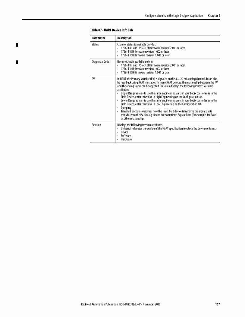
Configure Modules in the Logix Designer Application Chapter 9
Status Channel status is available only for:• 1756-IF8H and1756-OF8H firmware revision 2.001 or later• 1756-IF16H firmware revision 1.002 or later• 1756-IF16IH firmware revision 1.001 or later
Diagnostic Code Device status is available only for:• 1756-IF8H and1756-OF8H firmware revision 2.001 or later• 1756-IF16H firmware revision 1.002 or later• 1756-IF16IH firmware revision 1.001 or later
PV In HART, the Primary Variable (PV) is signaled on the 4…20 mA analog channel. It can also be read back using HART messages. In many HART devices, the relationship between the PV and the analog signal can be adjusted. This area displays the following Process Variable attributes:• Upper Range Value - to use the same engineering units in your Logix controller as in the
Field Device, enter this value in High Engineering on the Configuration tab.• Lower Range Value - to use the same engineering units in your Logix controller as in the
Field Device, enter this value in Low Engineering on the Configuration tab.• Damping• Transfer Function - describes how the HART field device transforms the signal on its
transducer to the PV. Usually Linear, but sometimes Square Root (for example, for flow), or other relationships.
Revision Displays the following revision attributes.• Universal - denotes the version of the HART specification to which the device conforms.• Device• Software• Hardware
Table 87 - HART Device Info Tab
Parameter Description
Rockwell Automation Publication 1756-UM533E-EN-P - November 2016 167
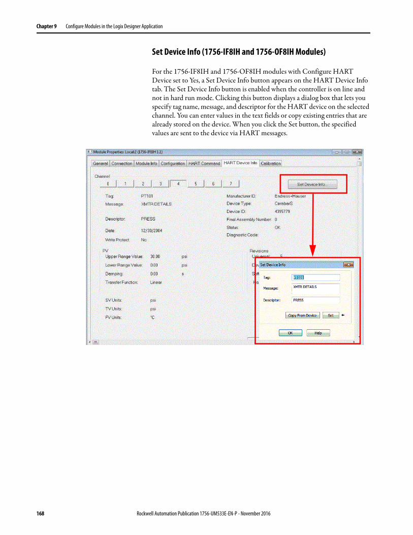
Chapter 9 Configure Modules in the Logix Designer Application
Set Device Info (1756-IF8IH and 1756-OF8IH Modules)
For the 1756-IF8IH and 1756-OF8IH modules with Configure HART Device set to Yes, a Set Device Info button appears on the HART Device Info tab. The Set Device Info button is enabled when the controller is on line and not in hard run mode. Clicking this button displays a dialog box that lets you specify tag name, message, and descriptor for the HART device on the selected channel. You can enter values in the text fields or copy existing entries that are already stored on the device. When you click the Set button, the specified values are sent to the device via HART messages.
168 Rockwell Automation Publication 1756-UM533E-EN-P - November 2016
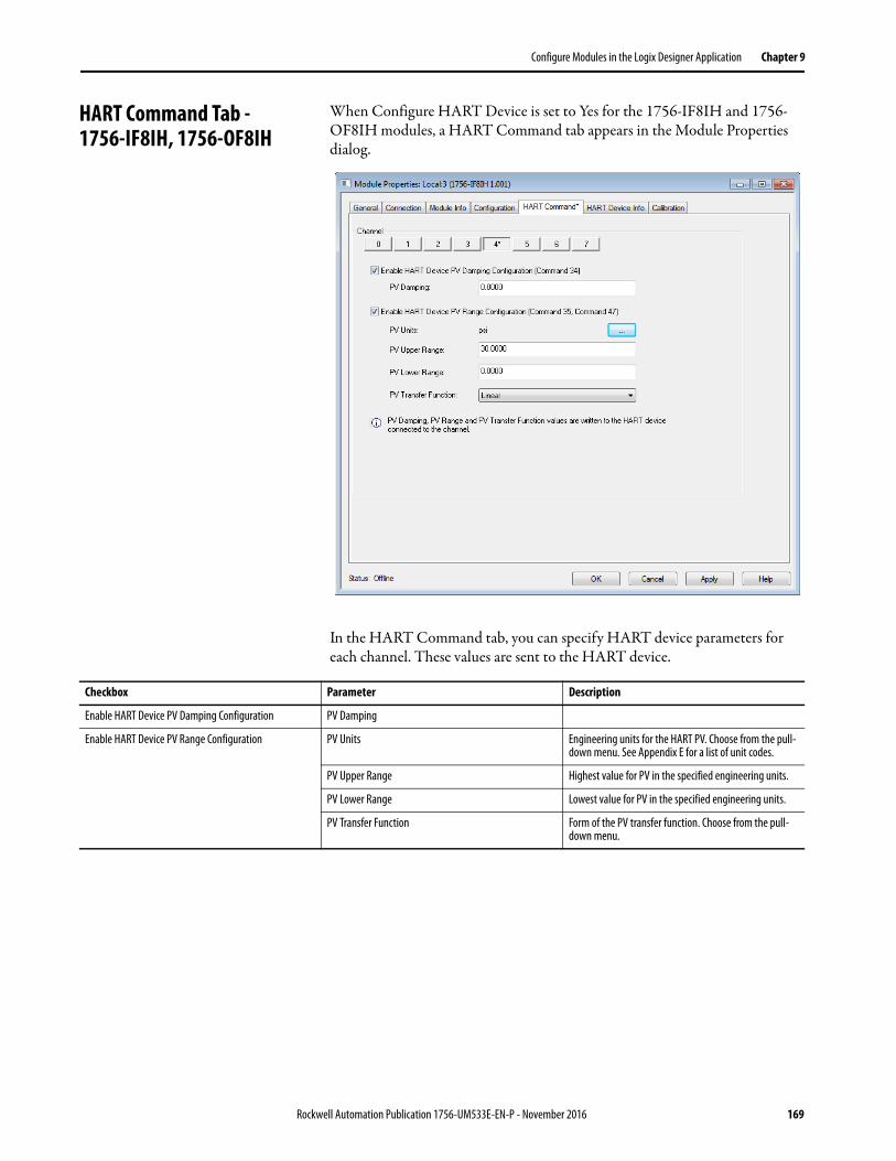
Configure Modules in the Logix Designer Application Chapter 9
HART Command Tab - 1756-IF8IH, 1756-OF8IH
When Configure HART Device is set to Yes for the 1756-IF8IH and 1756-OF8IH modules, a HART Command tab appears in the Module Properties dialog.
In the HART Command tab, you can specify HART device parameters for each channel. These values are sent to the HART device.
Checkbox Parameter Description
Enable HART Device PV Damping Configuration PV Damping
Enable HART Device PV Range Configuration PV Units Engineering units for the HART PV. Choose from the pull-down menu. See Appendix E for a list of unit codes.
PV Upper Range Highest value for PV in the specified engineering units.
PV Lower Range Lowest value for PV in the specified engineering units.
PV Transfer Function Form of the PV transfer function. Choose from the pull-down menu.
Rockwell Automation Publication 1756-UM533E-EN-P - November 2016 169
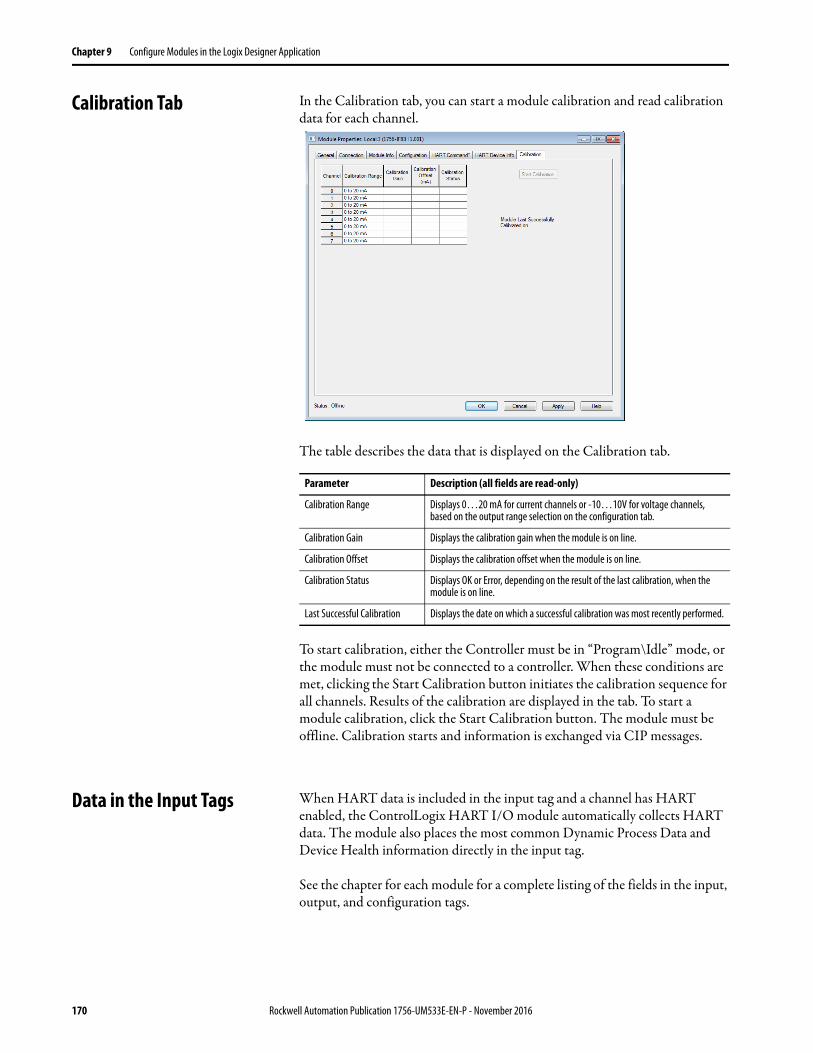
Chapter 9 Configure Modules in the Logix Designer Application
Calibration Tab In the Calibration tab, you can start a module calibration and read calibration data for each channel.
The table describes the data that is displayed on the Calibration tab.
To start calibration, either the Controller must be in “Program\Idle” mode, or the module must not be connected to a controller. When these conditions are met, clicking the Start Calibration button initiates the calibration sequence for all channels. Results of the calibration are displayed in the tab. To start a module calibration, click the Start Calibration button. The module must be offline. Calibration starts and information is exchanged via CIP messages.
Data in the Input Tags When HART data is included in the input tag and a channel has HART enabled, the ControlLogix HART I/O module automatically collects HART data. The module also places the most common Dynamic Process Data and Device Health information directly in the input tag.
See the chapter for each module for a complete listing of the fields in the input, output, and configuration tags.
Parameter Description (all fields are read-only)
Calibration Range Displays 0…20 mA for current channels or -10…10V for voltage channels, based on the output range selection on the configuration tab.
Calibration Gain Displays the calibration gain when the module is on line.
Calibration Offset Displays the calibration offset when the module is on line.
Calibration Status Displays OK or Error, depending on the result of the last calibration, when the module is on line.
Last Successful Calibration Displays the date on which a successful calibration was most recently performed.
170 Rockwell Automation Publication 1756-UM533E-EN-P - November 2016
Configure Modules in the Logix Designer Application Chapter 9
An overview of the HART data includes the following:• HART Faults - At the beginning of the input tag included even if you
click Analog Only input data tag format. These faults indicate that HART communication is not successful or that the field device is reporting a problem such as Device Malfunction, Loop Current Saturated or PV out of Limit. For example, Ch0HARTFault is set if Ch0Config.HARTEn is 0 or if no HART Field Device is attached.
• HART Device Status - A collection of status indicators that reflect the HART communication details and overall device health.– Init - Module is searching for a HART device.– Fault - HART communication is not successful. If this is 1 and
Initializing is 0, probable cause is HART is not enabled on this channel.
– Message Ready - A HART pass-through message reply is ready to be collected by using the Pass-through Query CIP message. See Chapter 10 for information on how to use CIP MSGs to access HART data.
– Current Fault - The analog current doesn't match the readback of the current received over the HART communication. An inaccurate field device, faulty wiring, or water in the conduit can cause this. Sometimes a rapid change in the signal results in a transient current fault as the analog and digital representations are sampled at slightly different times and at different places in the signal path.
– Configuration Changed - The Field Device configuration has changed and new Field Device configuration information can be obtained from the module via CIP MSG GetDeviceInfo, which clears this bit.
– ResponseCode - HART Communication Status or Response Code. 0 means success. See Configure Modules in the Logix Designer Application for details.
– FieldDeviceStatus - HART device health, such as PV out of range or device malfunction. See Appendix B for details.
– UpdatedStatusReady - indicates new device diagnostic information is available, which can be obtained by sending a CIP Message with Service 4C.
HART Dynamic Variables
Most HART devices can measure several different process characteristics or of deriving other measurements from directly sensed measurements. For example, many differential pressure transmitters can also sense the process temperature and can calculate the flow. These sensors can also calculate the volume in a tank based on a measurement of its head pressure and knowledge of tank geometry and product density.
Rockwell Automation Publication 1756-UM533E-EN-P - November 2016 171
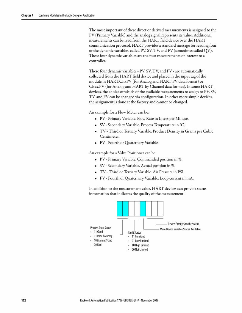
Chapter 9 Configure Modules in the Logix Designer Application
The most important of these direct or derived measurements is assigned to the PV (Primary Variable) and the analog signal represents its value. Additional measurements can be read from the HART field device over the HART communication protocol. HART provides a standard message for reading four of the dynamic variables, called PV, SV, TV, and FV (sometimes called QV). These four dynamic variables are the four measurements of interest to a controller.
These four dynamic variables - PV, SV, TV, and FV - are automatically collected from the HART field device and placed in the input tag of the module in HART.ChxPV (for Analog and HART PV data format) or Chxx.PV (for Analog and HART by Channel data format). In some HART devices, the choice of which of the available measurements to assign to PV, SV, TV, and FV can be changed via configuration. In other more simple devices, the assignment is done at the factory and cannot be changed.
An example for a Flow Meter can be:• PV - Primary Variable. Flow Rate in Liters per Minute.• SV - Secondary Variable. Process Temperature in °C.• TV - Third or Tertiary Variable. Product Density in Grams per Cubic
Centimeter.• FV - Fourth or Quaternary Variable
An example for a Valve Positioner can be:• PV - Primary Variable. Commanded position in %.• SV - Secondary Variable. Actual position in %.• TV - Third or Tertiary Variable. Air Pressure in PSI.• FV - Fourth or Quaternary Variable. Loop current in mA.
In addition to the measurement value, HART devices can provide status information that indicates the quality of the measurement.
Device Family Specific Status
More Device Variable Status AvailableLimit Status• 11 Constant• 01 Low Limited• 10 High Limited• 00 Not Limited
Process Data Status• 11 Good• 01 Poor Accuracy• 10 Manual/Fixed• 00 Bad
172 Rockwell Automation Publication 1756-UM533E-EN-P - November 2016
Configure Modules in the Logix Designer Application Chapter 9
For example, if a valve positioner cannot open any further, it can set its HART.ChxSVStatus to 2#11100000. This configuraiton indicates that the actual position value in the SV is Good (accurately measured) but is the subject of a High Limit. This status information can be used for windup control in PID loops and for other diagnostic purposes.
The module collects the PV, SV, TV, and FV data as described in Table 88.
Command 3 does not provide PVStatus, SVStatus, TVStatus, or FVStatus. HART devices that indicate Command 3 as shown in Table 88 have their Dynamic Variable Status values reported based on the communication status with the HART field device. If the Dynamic Variables are being collected without communication error, the Status value is 16#C0 (2#11000000), which means good. Otherwise, it is 0, meaning bad.
Some devices do not have four dynamic variables. In this case, they can report a NaN value to indicate that they have no valid value for that parameter.
The dynamic variables do not update as fast as the analog signal. The actual rate depends on the number of channels that are configured for HART (for the 8-channel modules), the number of pass-through message commands, the presence of handheld communicators or other secondary masters, and the response speed of the field device.
When eight channels are in use on the non-isolated 8-channel modules, the HART update rate is in the 10-second range.
Table 88 - Dynamic Variable Assignment(1)
(1) Table does not apply to the 1756-IF8H and 1756-OF8H modules, version 1.x, and the1756-IF16H and 1756-IF16IH modules, version 1.1
HART Version
HART Device Reports PV, SV, TV, FV Assignments in Command 50
HART Command Used by 1756 Module to Collect PV, SV, TV, FV
Device Variable Codes Used in Command 9 forPV, SV, TV, FV
5 – 3 –
6 No 3 –
Yes 9 As Reported in Command 50
7 or later No 9 246, 247, 248, 249
Yes As Reported in Command 50
IMPORTANT Verify that the actual HART update rate is appropriate for your application. Remember that pass-through message traffic, additional status information, secondary masters, and communication errors can delay the update rate. On the non-isolated 8-channel modules, because all channels share the HART modem, increased delay on one channel affects other channels also.
IMPORTANT Verify that HART data is valid by checking ChxFault, HARTFault, and values such as PVStatus and SVStatus.
Rockwell Automation Publication 1756-UM533E-EN-P - November 2016 173
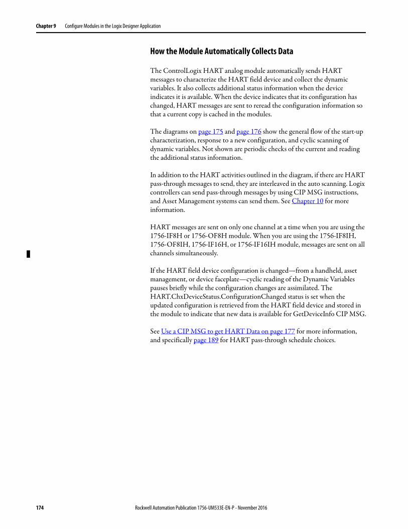
Chapter 9 Configure Modules in the Logix Designer Application
How the Module Automatically Collects Data
The ControlLogix HART analog module automatically sends HART messages to characterize the HART field device and collect the dynamic variables. It also collects additional status information when the device indicates it is available. When the device indicates that its configuration has changed, HART messages are sent to reread the configuration information so that a current copy is cached in the modules.
The diagrams on page 175 and page 176 show the general flow of the start-up characterization, response to a new configuration, and cyclic scanning of dynamic variables. Not shown are periodic checks of the current and reading the additional status information.
In addition to the HART activities outlined in the diagram, if there are HART pass-through messages to send, they are interleaved in the auto scanning. Logix controllers can send pass-through messages by using CIP MSG instructions, and Asset Management systems can send them. See Chapter 10 for more information.
HART messages are sent on only one channel at a time when you are using the 1756-IF8H or 1756-OF8H module. When you are using the 1756-IF8IH, 1756-OF8IH, 1756-IF16H, or 1756-IF16IH module, messages are sent on all channels simultaneously.
If the HART field device configuration is changed—from a handheld, asset management, or device faceplate—cyclic reading of the Dynamic Variables pauses briefly while the configuration changes are assimilated. The HART.ChxDeviceStatus.ConfigurationChanged status is set when the updated configuration is retrieved from the HART field device and stored in the module to indicate that new data is available for GetDeviceInfo CIP MSG.
See Use a CIP MSG to get HART Data on page 177 for more information, and specifically page 189 for HART pass-through schedule choices.
174 Rockwell Automation Publication 1756-UM533E-EN-P - November 2016
Configure Modules in the Logix Designer Application Chapter 9
Figure 32 - 1756-IF8H and 1756-OF8H Flowchart
Yes
Update Input Tag
Device in Scan List?
Send Command 3 or 9 to Read Dynamic Process Variable
Reply?
Read Configuration Information, Such as Tag, Units, Range
Put Device in Scan List
Send Command 0 Read Unique Identifier
New Configuration
Indicated?
Remove Device from Scan List
Read Configuration Information, Such As Tag, Units, Range
Signal Configuration Changed in Input Tag
Go To First Channel
Next Channel
LastChannel?
No
Signal Configuration Changed in Input Tag
Yes
Reply?Yes
No
Yes
Process 1 Pass-through Message
No
No
No
Yes
Rockwell Automation Publication 1756-UM533E-EN-P - November 2016 175

Chapter 9 Configure Modules in the Logix Designer Application
Figure 33 - 1756-IF8IH, 1756-OF8IH, 1756-IF16H, and 1756-IF16IH Modules Flowchart
Yes
Update Input Tag
Device in Scan List?
Send Command 3 or 9 to Read Dynamic Process Variable
Reply?
Read Configuration Information, Such as Tag, Units, Range
Put Device in Scan List
Send Command 0 Read Unique Identifier
New Configuration
Indicated?
Remove Device from Scan List
Read Configuration Information, Such As Tag, Units, Range
Signal Configuration Changed in Input Tag
No
Signal Configuration Changed in Input Tag
Yes
Reply?Yes
No
Process 1 Pass- through Message
No
No
Yes
176 Rockwell Automation Publication 1756-UM533E-EN-P - November 2016
Chapter 10
Use a CIP MSG to get HART Data
This chapter discusses these topics.
This chapter shows how to use HART data in your Logix controller via MSG instructions. Examples of reasons to do this include the following:
• You need only occasional access to the data, and do not want to use the extra network capacity and memory that is required for the Analog with HART PV or Analog and HART by Channel input tags.
• You need extra information, such as device tag, ranges, or manufacturer-specific information.
• You must send a manufacturer-specific command to the HART device.
Usually, everything you must use a HART instrument is automatically collected and placed in the input tag, and these CIP MSG instructions are not needed.
The 1756 ControlLogix® HART analog modules support these broad categories of MSG-based HART access:
• CIP formatted messages to retrieve common HART data cached in the module.
• CIP messages that contain HART formatted commands that are passed directly to the HART field device for processing. These messages are called pass-through messages.
By using these mechanisms your Logix controller has easy access to some commonly used data and, with some extra effort, access to any HART feature.
The features that are described in this chapter use MSG instructions. For more information and examples about MSG instructions, refer to Chapter 12, which explains how to use MSG instructions to unlatch alarms or reconfigure modules.
Topic Page
Use MSG Instructions to Access the HART Object 178
CIP Services to Access Common HART Data 179
Use a CIP Generic MSG to get HART Device Information 184
CIP Services to Pass-through a HART Message to the HART Field Device 187
HART Module Scanning Diagram with Pass-through Messages 189
HART Pass-through CIP Message Layout Details 191
HART Pass-through Message Ladder Logic Example 194
Rockwell Automation Publication 1756-UM533E-EN-P - November 2016 177
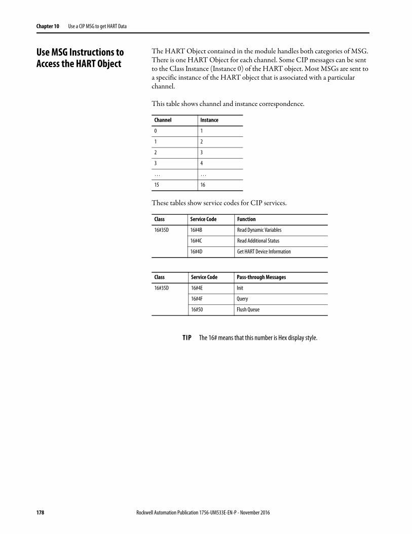
Chapter 10 Use a CIP MSG to get HART Data
Use MSG Instructions to Access the HART Object
The HART Object contained in the module handles both categories of MSG. There is one HART Object for each channel. Some CIP messages can be sent to the Class Instance (Instance 0) of the HART object. Most MSGs are sent to a specific instance of the HART object that is associated with a particular channel.
This table shows channel and instance correspondence.
These tables show service codes for CIP services.
Channel Instance
0 1
1 2
2 3
3 4
… …
15 16
Class Service Code Function
16#35D 16#4B Read Dynamic Variables
16#4C Read Additional Status
16#4D Get HART Device Information
Class Service Code Pass-through Messages
16#35D 16#4E Init
16#4F Query
16#50 Flush Queue
TIP The 16# means that this number is Hex display style.
178 Rockwell Automation Publication 1756-UM533E-EN-P - November 2016
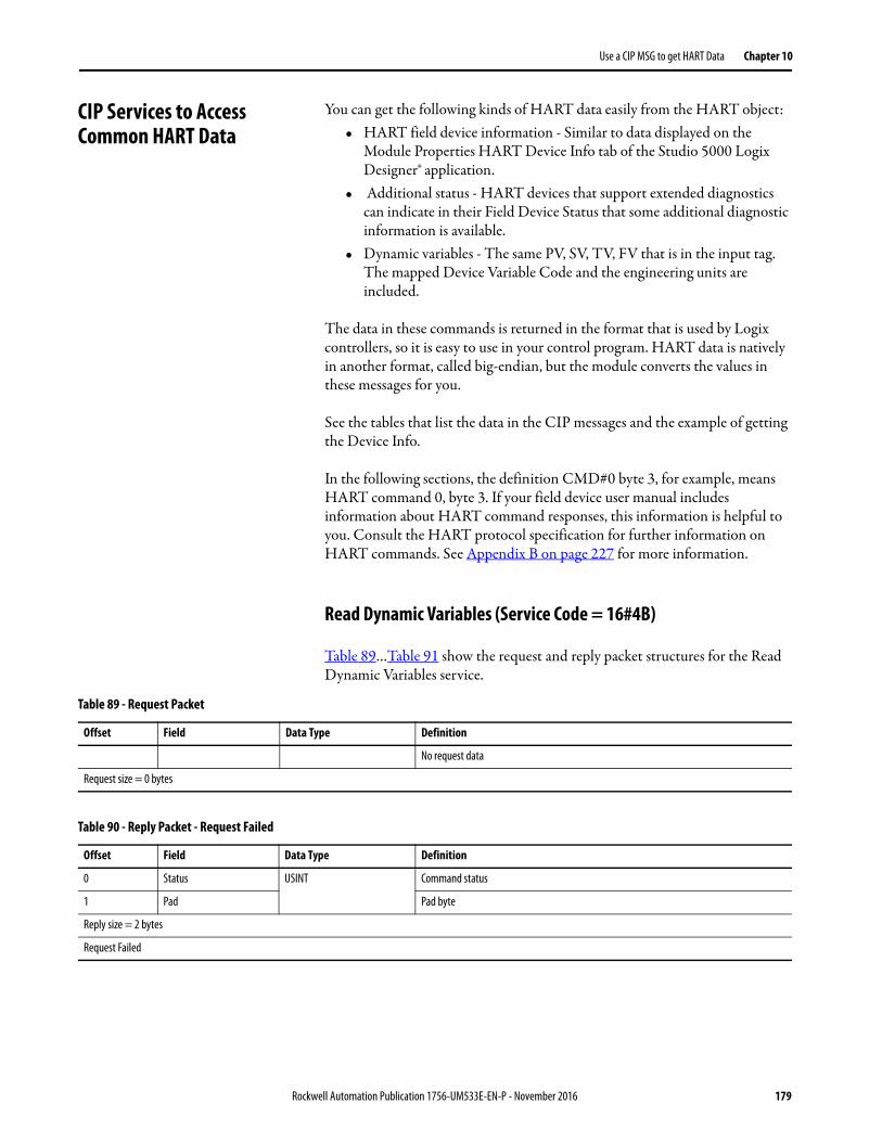
Use a CIP MSG to get HART Data Chapter 10
CIP Services to Access Common HART Data
You can get the following kinds of HART data easily from the HART object:• HART field device information - Similar to data displayed on the
Module Properties HART Device Info tab of the Studio 5000 Logix Designer® application.
• Additional status - HART devices that support extended diagnostics can indicate in their Field Device Status that some additional diagnostic information is available.
• Dynamic variables - The same PV, SV, TV, FV that is in the input tag. The mapped Device Variable Code and the engineering units are included.
The data in these commands is returned in the format that is used by Logix controllers, so it is easy to use in your control program. HART data is natively in another format, called big-endian, but the module converts the values in these messages for you.
See the tables that list the data in the CIP messages and the example of getting the Device Info.
In the following sections, the definition CMD#0 byte 3, for example, means HART command 0, byte 3. If your field device user manual includes information about HART command responses, this information is helpful to you. Consult the HART protocol specification for further information on HART commands. See Appendix B on page 227 for more information.
Read Dynamic Variables (Service Code = 16#4B)
Table 89…Table 91 show the request and reply packet structures for the Read Dynamic Variables service.
Table 89 - Request Packet
Offset Field Data Type Definition
No request data
Request size = 0 bytes
Table 90 - Reply Packet - Request Failed
Offset Field Data Type Definition
0 Status USINT Command status
1 Pad Pad byte
Reply size = 2 bytes
Request Failed
Rockwell Automation Publication 1756-UM533E-EN-P - November 2016 179
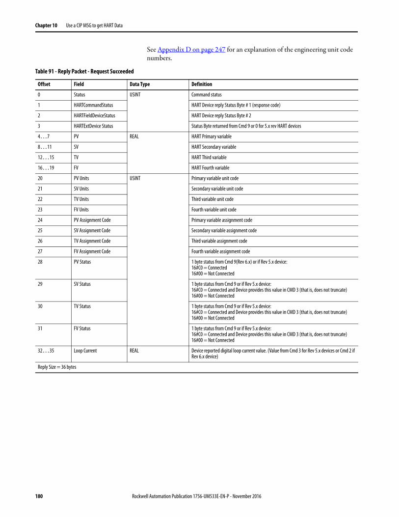
Chapter 10 Use a CIP MSG to get HART Data
See Appendix D on page 247 for an explanation of the engineering unit code numbers.
Table 91 - Reply Packet - Request Succeeded
Offset Field Data Type Definition
0 Status USINT Command status
1 HARTCommandStatus HART Device reply Status Byte # 1 (response code)
2 HARTFieldDeviceStatus HART Device reply Status Byte # 2
3 HARTExtDevice Status Status Byte returned from Cmd 9 or 0 for 5.x rev HART devices
4…7 PV REAL HART Primary variable
8…11 SV HART Secondary variable
12…15 TV HART Third variable
16…19 FV HART Fourth variable
20 PV Units USINT Primary variable unit code
21 SV Units Secondary variable unit code
22 TV Units Third variable unit code
23 FV Units Fourth variable unit code
24 PV Assignment Code Primary variable assignment code
25 SV Assignment Code Secondary variable assignment code
26 TV Assignment Code Third variable assignment code
27 FV Assignment Code Fourth variable assignment code
28 PV Status 1 byte status from Cmd 9(Rev 6.x) or if Rev 5.x device:16#C0 = Connected16#00 = Not Connected
29 SV Status 1 byte status from Cmd 9 or if Rev 5.x device:16#C0 = Connected and Device provides this value in CMD 3 (that is, does not truncate)16#00 = Not Connected
30 TV Status 1 byte status from Cmd 9 or if Rev 5.x device: 16#C0 = Connected and Device provides this value in CMD 3 (that is, does not truncate)16#00 = Not Connected
31 FV Status 1 byte status from Cmd 9 or if Rev 5.x device:16#C0 = Connected and Device provides this value in CMD 3 (that is, does not truncate)16#00 = Not Connected
32…35 Loop Current REAL Device reported digital loop current value. (Value from Cmd 3 for Rev 5.x devices or Cmd 2 if Rev 6.x device)
Reply Size = 36 bytes
180 Rockwell Automation Publication 1756-UM533E-EN-P - November 2016
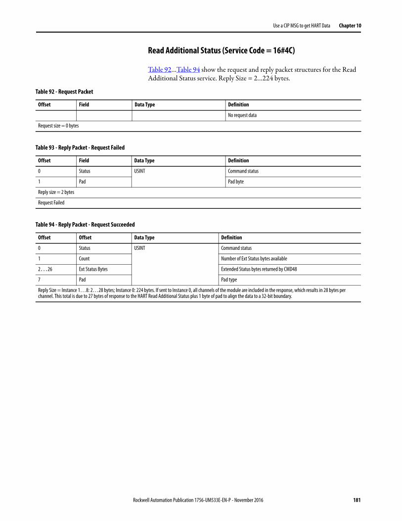
Use a CIP MSG to get HART Data Chapter 10
Read Additional Status (Service Code = 16#4C)
Table 92…Table 94 show the request and reply packet structures for the Read Additional Status service. Reply Size = 2…224 bytes.
Table 92 - Request Packet
Offset Field Data Type Definition
No request data
Request size = 0 bytes
Table 93 - Reply Packet - Request Failed
Offset Field Data Type Definition
0 Status USINT Command status
1 Pad Pad byte
Reply size = 2 bytes
Request Failed
Table 94 - Reply Packet - Request Succeeded
Offset Offset Data Type Definition
0 Status USINT Command status
1 Count Number of Ext Status bytes available
2…26 Ext Status Bytes Extended Status bytes returned by CMD48
7 Pad Pad type
Reply Size = Instance 1…8: 2…28 bytes; Instance 0: 224 bytes. If sent to Instance 0, all channels of the module are included in the response, which results in 28 bytes per channel. This total is due to 27 bytes of response to the HART Read Additional Status plus 1 byte of pad to align the data to a 32-bit boundary.
Rockwell Automation Publication 1756-UM533E-EN-P - November 2016 181
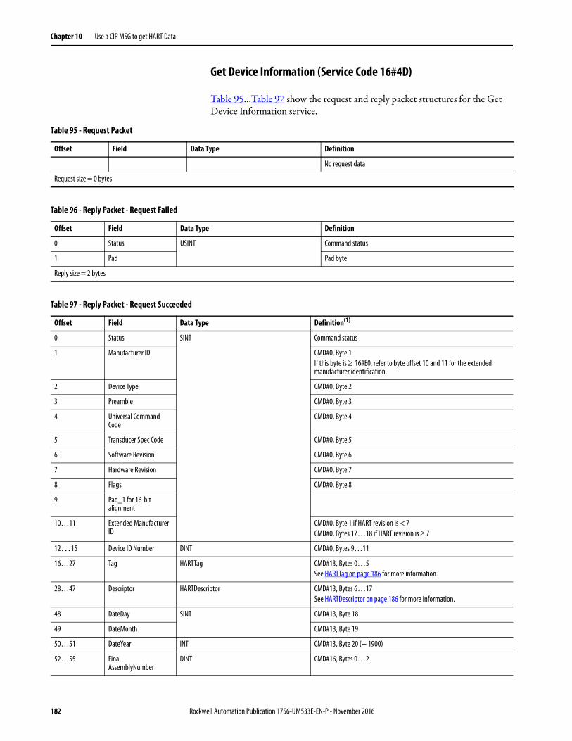
Chapter 10 Use a CIP MSG to get HART Data
Get Device Information (Service Code 16#4D)
Table 95…Table 97 show the request and reply packet structures for the Get Device Information service.
Table 95 - Request Packet
Offset Field Data Type Definition
No request data
Request size = 0 bytes
Table 96 - Reply Packet - Request Failed
Offset Field Data Type Definition
0 Status USINT Command status
1 Pad Pad byte
Reply size = 2 bytes
Table 97 - Reply Packet - Request Succeeded
Offset Field Data Type Definition(1)
0 Status SINT Command status
1 Manufacturer ID CMD#0, Byte 1If this byte is 16#E0, refer to byte offset 10 and 11 for the extended manufacturer identification.
2 Device Type CMD#0, Byte 2
3 Preamble CMD#0, Byte 3
4 Universal Command Code
CMD#0, Byte 4
5 Transducer Spec Code CMD#0, Byte 5
6 Software Revision CMD#0, Byte 6
7 Hardware Revision CMD#0, Byte 7
8 Flags CMD#0, Byte 8
9 Pad_1 for 16-bit alignment
10…11 Extended Manufacturer ID
CMD#0, Byte 1 if HART revision is < 7CMD#0, Bytes 17…18 if HART revision is 7
12…15 Device ID Number DINT CMD#0, Bytes 9…11
16…27 Tag HARTTag CMD#13, Bytes 0…5See HARTTag on page 186 for more information.
28…47 Descriptor HARTDescriptor CMD#13, Bytes 6…17See HARTDescriptor on page 186 for more information.
48 DateDay SINT CMD#13, Byte 18
49 DateMonth CMD#13, Byte 19
50…51 DateYear INT CMD#13, Byte 20 (+ 1900)
52…55 FinalAssemblyNumber
DINT CMD#16, Bytes 0…2
182 Rockwell Automation Publication 1756-UM533E-EN-P - November 2016
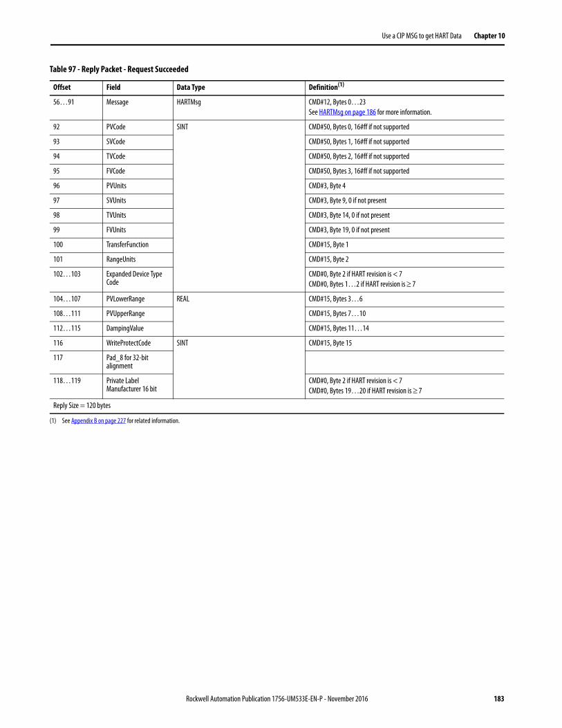
Use a CIP MSG to get HART Data Chapter 10
56…91 Message HARTMsg CMD#12, Bytes 0…23See HARTMsg on page 186 for more information.
92 PVCode SINT CMD#50, Bytes 0, 16#ff if not supported
93 SVCode CMD#50, Bytes 1, 16#ff if not supported
94 TVCode CMD#50, Bytes 2, 16#ff if not supported
95 FVCode CMD#50, Bytes 3, 16#ff if not supported
96 PVUnits CMD#3, Byte 4
97 SVUnits CMD#3, Byte 9, 0 if not present
98 TVUnits CMD#3, Byte 14, 0 if not present
99 FVUnits CMD#3, Byte 19, 0 if not present
100 TransferFunction CMD#15, Byte 1
101 RangeUnits CMD#15, Byte 2
102…103 Expanded Device Type Code
CMD#0, Byte 2 if HART revision is < 7CMD#0, Bytes 1…2 if HART revision is 7
104…107 PVLowerRange REAL CMD#15, Bytes 3…6
108…111 PVUpperRange CMD#15, Bytes 7…10
112…115 DampingValue CMD#15, Bytes 11…14
116 WriteProtectCode SINT CMD#15, Byte 15
117 Pad_8 for 32-bit alignment
118…119 Private Label Manufacturer 16 bit
CMD#0, Byte 2 if HART revision is < 7CMD#0, Bytes 19…20 if HART revision is 7
Reply Size = 120 bytes
(1) See Appendix B on page 227 for related information.
Table 97 - Reply Packet - Request Succeeded
Offset Field Data Type Definition(1)
Rockwell Automation Publication 1756-UM533E-EN-P - November 2016 183
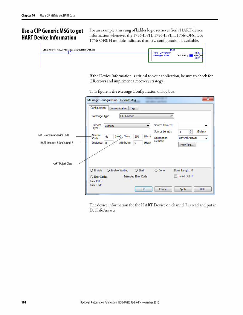
Chapter 10 Use a CIP MSG to get HART Data
Use a CIP Generic MSG to get HART Device Information
For an example, this rung of ladder logic retrieves fresh HART device information whenever the 1756-IF8H, 1756-IF8IH, 1756-OF8H, or 1756-OF8IH module indicates that new configuration is available.
If the Device Information is critical to your application, be sure to check for .ER errors and implement a recovery strategy.
This figure is the Message Configuration dialog box.
The device information for the HART Device on channel 7 is read and put in DevInfoAnswer.
Get Device Info Service Code
HART Instance 8 for Channel 7
HART Object Class
184 Rockwell Automation Publication 1756-UM533E-EN-P - November 2016
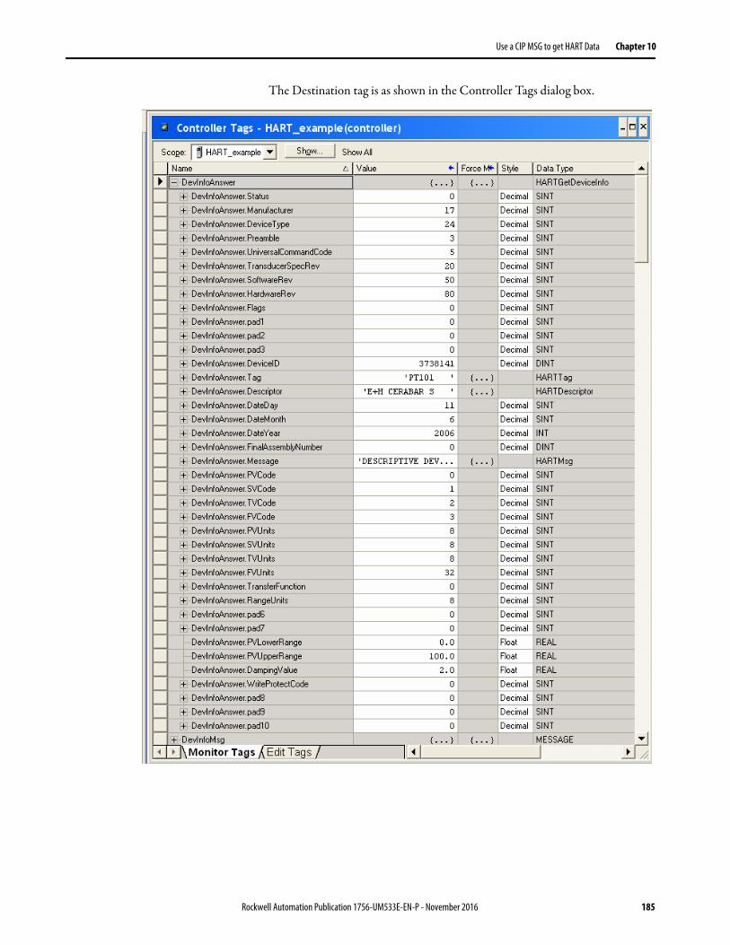
Use a CIP MSG to get HART Data Chapter 10
The Destination tag is as shown in the Controller Tags dialog box.
Rockwell Automation Publication 1756-UM533E-EN-P - November 2016 185
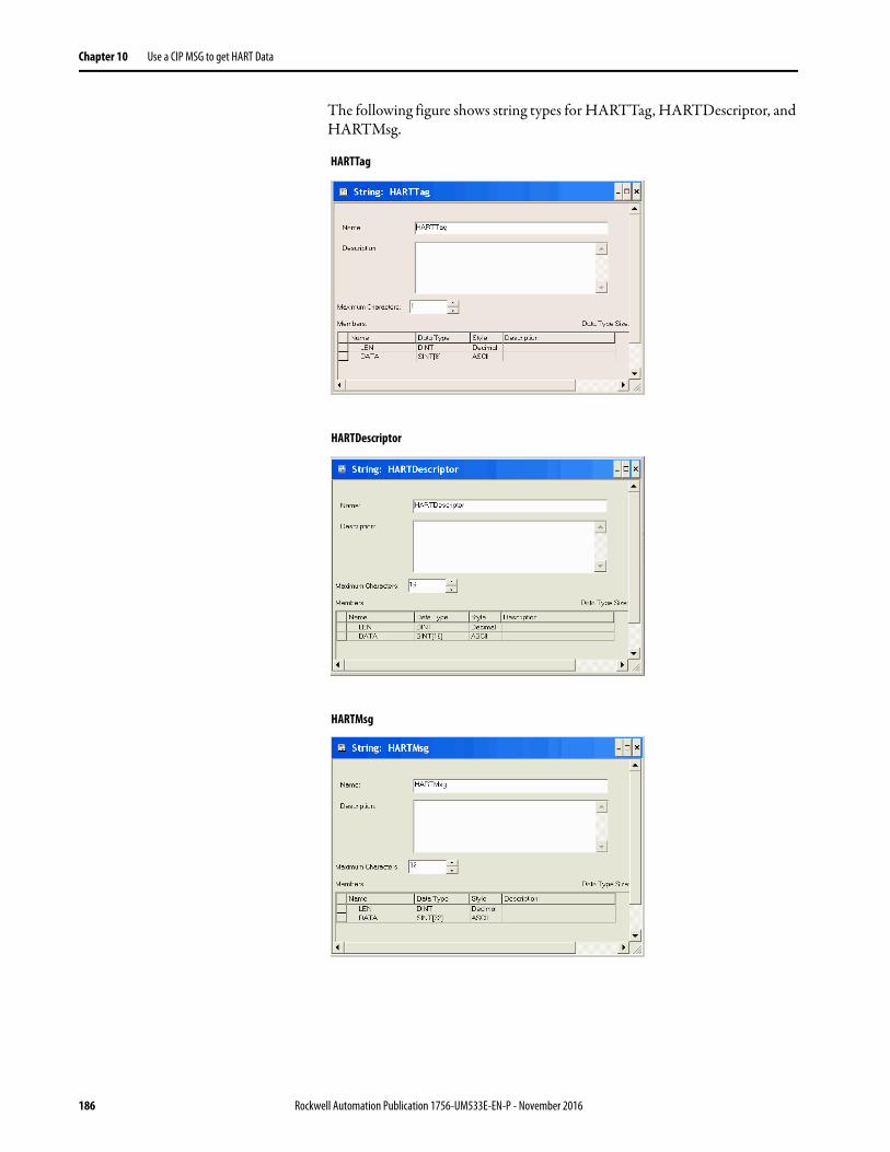
Chapter 10 Use a CIP MSG to get HART Data
The following figure shows string types for HARTTag, HARTDescriptor, and HARTMsg.
HARTDescriptor
HARTMsg
HARTTag
186 Rockwell Automation Publication 1756-UM533E-EN-P - November 2016
Use a CIP MSG to get HART Data Chapter 10
CIP Services to Pass-through a HART Message to the HART Field Device
The HART object supports these CIP messages for HART pass-through messaging: Pass-through Init, Pass-through Query, Flush Queue (rarely needed).
With these three CIP messages, your Logix controller can format the individual bytes of a HART command, send it to a HART field device, and retrieve the response in HART format.
Native HART data is in another format than used by Logix controllers. HART uses the big-endian format and Logix uses little-endian format. This means the order of the bytes in a number is in the opposite order so they must be reversed before use. Logix little-endian means that the least significant byte of a number is stored at the lowest address (array index).
Logix also aligns data on boundaries that permit fast access and HART packs them into the smallest space. HART encodes text strings using 6 bits per letter into a format called Packed ASCII. When using pass-through messaging, your Logix program must be aware of these data layout issues.
The pass-through message CIP services that are supported by the HART object are simplified. The module provides the 5-byte address required by HART messages and the Checksum is calculated automatically for you.
Follow these steps to send a HART pass-through message.
1. Send a CIP message to tell the 1756-IF8H, 1756-IF8IH, 1756-OF8H, or 1756-OF8IH module to send a message to a HART field device (Init).
2. Send a CIP message to retrieve the HART Reply from the 1756-IF8H, 1756-IF8IH, 1756-OF8H, or 1756-OF8IH module (Query).
Pass-through InitPass-through Query
HART Reply Bytes
Handle
Destination
MSG
Source
Source
Handle
Destination
HART Command BytesMSG
Service 16#4F
Service 16#4E
44405
Rockwell Automation Publication 1756-UM533E-EN-P - November 2016 187
Chapter 10 Use a CIP MSG to get HART Data
If your input tag includes the HART PV data, a status indicator HART.ChxDeviceStatus.MsgReady tells your program that a HART reply is ready to retrieve with the Pass-through Query command.
The CIP reply from the Init service includes a number that is called the handle. This handle identifies the HART message that was placed in a queue for transmission to the field device. When the reply is received and MsgReady is set to 1, your Logix controller sends a Query containing that same handle to retrieve the HART reply. The reason these steps are necessary is that it can take a long time for the HART command to be transmitted and a reply received. If all eight channels are in use, the time for a reply would be about 10 seconds if there was no other pass-through traffic.
188 Rockwell Automation Publication 1756-UM533E-EN-P - November 2016
Use a CIP MSG to get HART Data Chapter 10
HART Module Scanning Diagram with Pass-through Messages
When HART pass-through messages are being sent, the normal data acquisition sequence is modified as shown in the diagram. In this case, the Pass-through is configured to send one pass-through message for each channel scanned.
It can be configured for lower priority on the Configuration tab of the Module Properties dialog box.
Figure 34 - 1756-IF8H and 1756-OF8H Flowchart.
Yes
Update Input Tag
Device in Scan List?
Send Command 3 or 9 to Read Dynamic Process Variable
Reply?
Read Configuration Information, Such as Tag, Units, Range
Put Device in Scan List
Send Command 0 Read Unique Identifier
New Configuration
Indicated?
Remove Device from Scan List
Read Configuration Information, Such As Tag, Units, Range
Signal Configuration Changed in Input Tag
Go To First Channel
Next Channel
LastChannel?
No
Signal Configuration Changed in Input Tag
Yes
Reply?Yes
No
Yes
Process 1 Pass- through Message
No
No
No
Yes
Rockwell Automation Publication 1756-UM533E-EN-P - November 2016 189
Chapter 10 Use a CIP MSG to get HART Data
Figure 35 - 1756-IF8IH, 1756-OF8IH, 1756-IF16H, and 1756-IF16IH Modules Flowchart
Yes
Update Input Tag
Device in Scan List?
Send Command 3 or 9 to Read Dynamic Process Variable
Reply?
Read Configuration Information, Such as Tag, Units, Range
Put Device in Scan List
Send Command 0 Read Unique Identifier
New Configuration
Indicated?
Remove Device from Scan List
Read Configuration Information, Such As Tag, Units, Range
Signal Configuration Changed in Input Tag
No
Signal Configuration Changed in Input Tag
Yes
Reply?Yes
No
Process 1 Pass- through Message
No
No
Yes
190 Rockwell Automation Publication 1756-UM533E-EN-P - November 2016
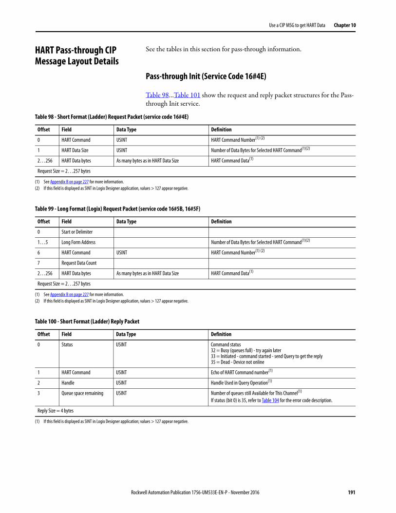
Use a CIP MSG to get HART Data Chapter 10
HART Pass-through CIP Message Layout Details
See the tables in this section for pass-through information.
Pass-through Init (Service Code 16#4E)
Table 98…Table 101 show the request and reply packet structures for the Pass-through Init service.
Table 98 - Short Format (Ladder) Request Packet (service code 16#4E)
Offset Field Data Type Definition
0 HART Command USINT HART Command Number(1) (2)
1 HART Data Size USINT Number of Data Bytes for Selected HART Command(1)(2)
2…256 HART Data bytes As many bytes as in HART Data Size HART Command Data(1)
Request Size = 2…257 bytes
(1) See Appendix B on page 227 for more information. (2) If this field is displayed as SINT in Logix Designer application, values > 127 appear negative.
Table 99 - Long Format (Logix) Request Packet (service code 16#5B, 16#5F)
Offset Field Data Type Definition
0 Start or Delimiter
1…5 Long Form Address Number of Data Bytes for Selected HART Command(1)(2)
6 HART Command USINT HART Command Number(1) (2)
7 Request Data Count
2…256 HART Data bytes As many bytes as in HART Data Size HART Command Data(1)
Request Size = 2…257 bytes
(1) See Appendix B on page 227 for more information. (2) If this field is displayed as SINT in Logix Designer application, values > 127 appear negative.
Table 100 - Short Format (Ladder) Reply Packet
Offset Field Data Type Definition
0 Status USINT Command status32 = Busy (queues full) - try again later33 = Initiated - command started - send Query to get the reply35 = Dead - Device not online
1 HART Command USINT Echo of HART Command number(1)
2 Handle USINT Handle Used in Query Operation(1)
3 Queue space remaining USINT Number of queues still Available for This Channel(1)
If status (bit 0) is 35, refer to Table 104 for the error code description.
Reply Size = 4 bytes
(1) If this field is displayed as SINT in Logix Designer application; values > 127 appear negative.
Rockwell Automation Publication 1756-UM533E-EN-P - November 2016 191
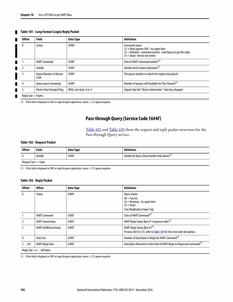
Chapter 10 Use a CIP MSG to get HART Data
Pass-through Query (Service Code 16#4F)
Table 102 and Table 103 show the request and reply packet structures for the Pass-through Query service.
Table 101 - Long Format (Logix) Reply Packet
Offset Field Data Type Definition
0 Status USINT Command status32 = Busy (queues full) - try again later33 = Initiated - command started - send Query to get the reply35 = Dead - Device not online
1 HART Command USINT Echo of HART Command number(1)
2 Handle USINT Handle Used in Query Operation(1)
3 Queue Number or Reason Code
USINT The queue number in which the request was placed
4 Queue space remaining USINT Number of queues still Available for This Channel(1)
5 Device Data Changed Flag BOOL (one byte, 0 or 1) Signals that the “Device Information “ data has changed
Reply Size = 4 bytes
(1) If this field is displayed as SINT in Logix Designer application, values > 127 appear negative.
Table 102 - Request Packet
Offset Field Data Type Definition
0 Handle USINT Handle for Query (from Handle Field above)(1)
Request Size = 1 byte
(1) If this field is displayed as SINT in Logix Designer application, values > 127 appear negative.
Table 103 - Reply Packet
Offset Offset Data Type Definition
0 Status USINT Query Status00 = Success34 = Running - try again later35 = Dead(See MsgReady in Input Tag)
1 HART Command USINT Echo of HART Command(1)
2 HART CommStatus USINT HART Reply Status Byte #1 (response code)(1)
3 HART FieldDeviceStatus USINT HART Reply Status Byte #2(1)
If status (bit 0) is 35, refer to Table 104 for the error code description.
4 Data Size USINT Number of Data Bytes in Reply for HART Command(1)
5…259 HART Reply Data … USINT Data Bytes Returned in Data Field of HART Reply to Requested Command(1)
Reply Size = 6…260 bytes
(1) If this field is displayed as SINT in Logix Designer application, values > 127 appear negative.
192 Rockwell Automation Publication 1756-UM533E-EN-P - November 2016
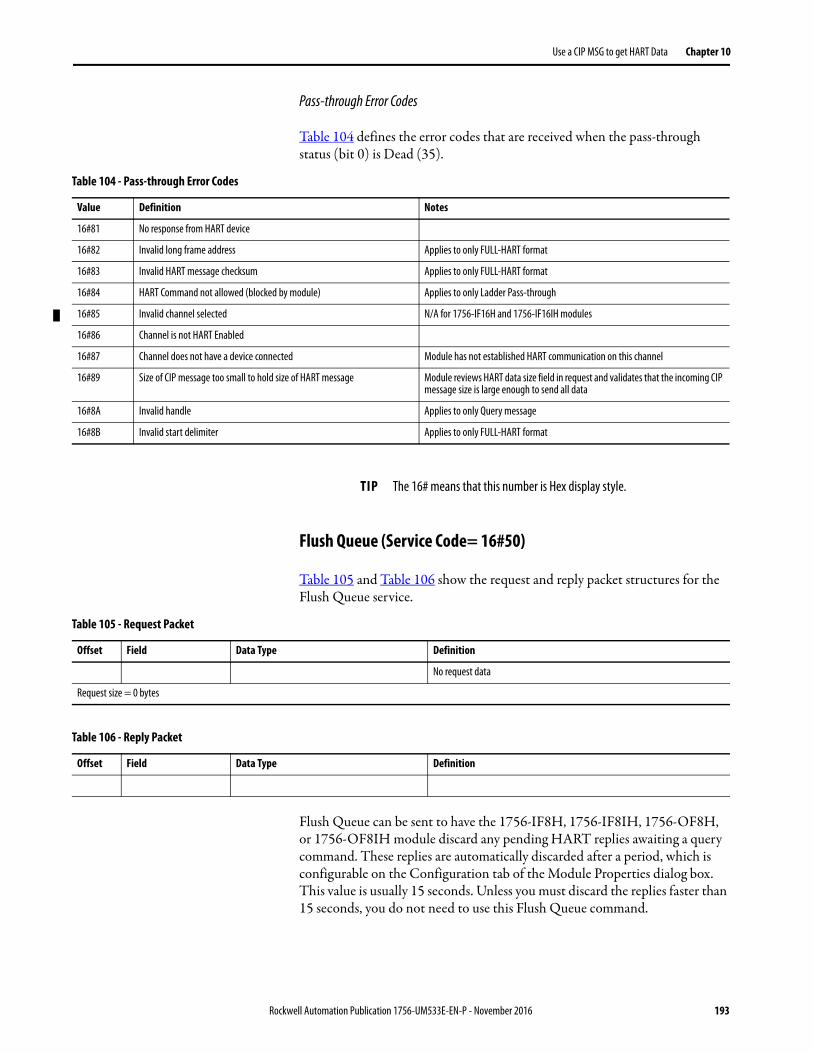
Use a CIP MSG to get HART Data Chapter 10
Pass-through Error Codes
Table 104 defines the error codes that are received when the pass-through status (bit 0) is Dead (35).
Flush Queue (Service Code= 16#50)
Table 105 and Table 106 show the request and reply packet structures for the Flush Queue service.
Flush Queue can be sent to have the 1756-IF8H, 1756-IF8IH, 1756-OF8H, or 1756-OF8IH module discard any pending HART replies awaiting a query command. These replies are automatically discarded after a period, which is configurable on the Configuration tab of the Module Properties dialog box. This value is usually 15 seconds. Unless you must discard the replies faster than 15 seconds, you do not need to use this Flush Queue command.
Table 104 - Pass-through Error Codes
Value Definition Notes
16#81 No response from HART device
16#82 Invalid long frame address Applies to only FULL-HART format
16#83 Invalid HART message checksum Applies to only FULL-HART format
16#84 HART Command not allowed (blocked by module) Applies to only Ladder Pass-through
16#85 Invalid channel selected N/A for 1756-IF16H and 1756-IF16IH modules
16#86 Channel is not HART Enabled
16#87 Channel does not have a device connected Module has not established HART communication on this channel
16#89 Size of CIP message too small to hold size of HART message Module reviews HART data size field in request and validates that the incoming CIP message size is large enough to send all data
16#8A Invalid handle Applies to only Query message
16#8B Invalid start delimiter Applies to only FULL-HART format
TIP The 16# means that this number is Hex display style.
Table 105 - Request Packet
Offset Field Data Type Definition
No request data
Request size = 0 bytes
Table 106 - Reply Packet
Offset Field Data Type Definition
Rockwell Automation Publication 1756-UM533E-EN-P - November 2016 193
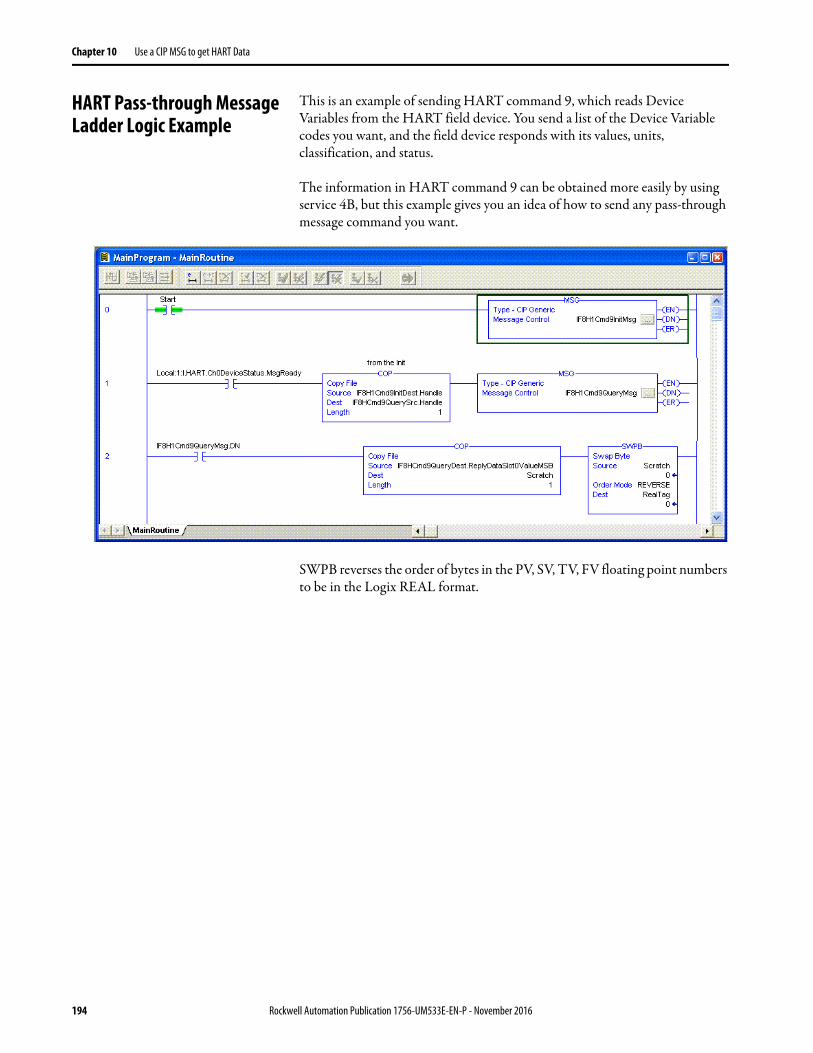
Chapter 10 Use a CIP MSG to get HART Data
HART Pass-through Message Ladder Logic Example
This is an example of sending HART command 9, which reads Device Variables from the HART field device. You send a list of the Device Variable codes you want, and the field device responds with its values, units, classification, and status.
The information in HART command 9 can be obtained more easily by using service 4B, but this example gives you an idea of how to send any pass-through message command you want.
SWPB reverses the order of bytes in the PV, SV, TV, FV floating point numbers to be in the Logix REAL format.
194 Rockwell Automation Publication 1756-UM533E-EN-P - November 2016
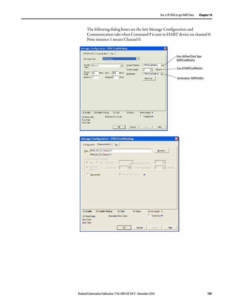
Use a CIP MSG to get HART Data Chapter 10
The following dialog boxes are the Init Message Configuration and Communication tabs when Command 9 is sent to HART device on channel 0. Note instance 1 means Channel 0.
User-defined Data Type: HARTCmd9InitSrc
Size of HARTCmd9InitSrc
Destination: HARTInitDst
Rockwell Automation Publication 1756-UM533E-EN-P - November 2016 195
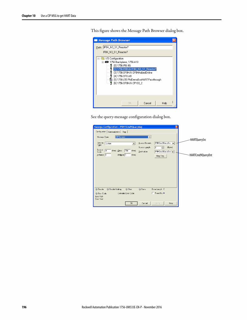
Chapter 10 Use a CIP MSG to get HART Data
This figure shows the Message Path Browser dialog box.
See the query-message configuration dialog box.
HARTQuerySrc
HARTCmd9QueryDst
196 Rockwell Automation Publication 1756-UM533E-EN-P - November 2016
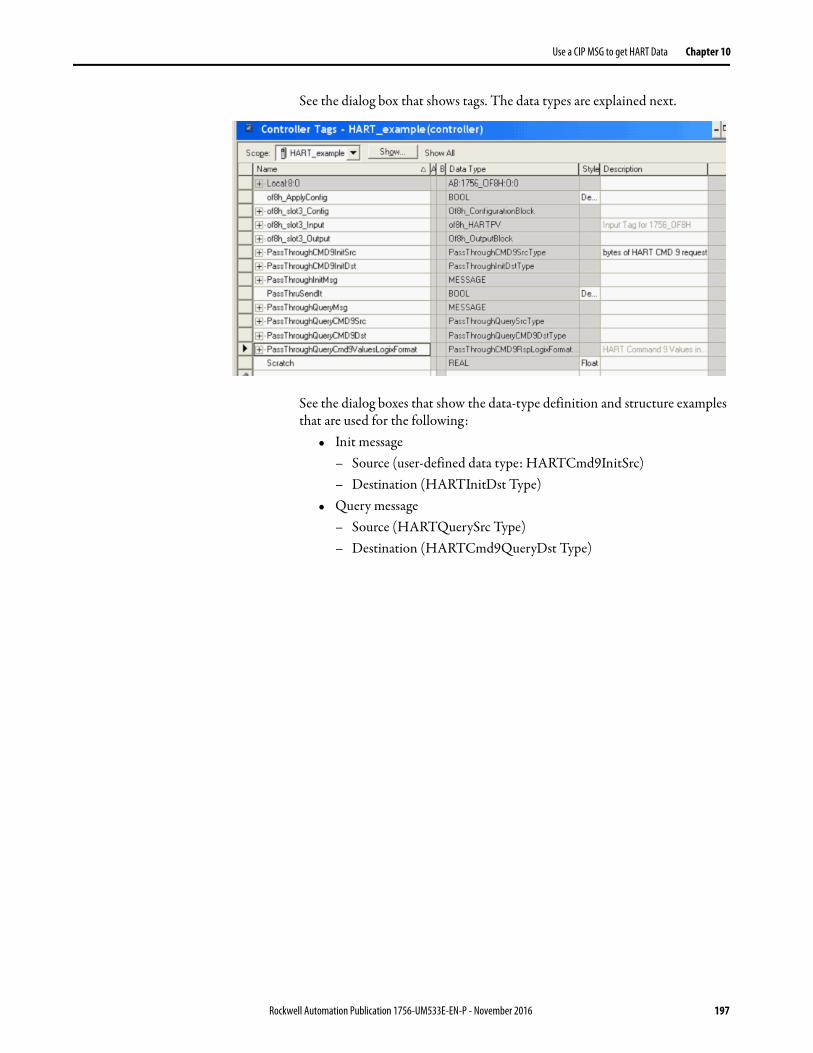
Use a CIP MSG to get HART Data Chapter 10
See the dialog box that shows tags. The data types are explained next.
See the dialog boxes that show the data-type definition and structure examples that are used for the following:
• Init message– Source (user-defined data type: HARTCmd9InitSrc)– Destination (HARTInitDst Type)
• Query message– Source (HARTQuerySrc Type)– Destination (HARTCmd9QueryDst Type)
Rockwell Automation Publication 1756-UM533E-EN-P - November 2016 197
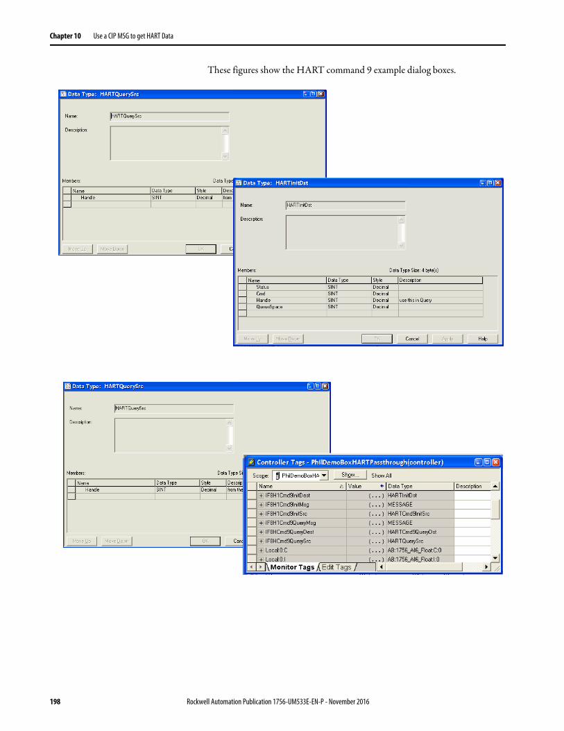
Chapter 10 Use a CIP MSG to get HART Data
These figures show the HART command 9 example dialog boxes.
198 Rockwell Automation Publication 1756-UM533E-EN-P - November 2016
Chapter 11
HART Modules Used with AssetManagement Software
These topics are discussed in this chapter.
Considerations for Asset Management Systems
The following must be considered before using the I/O modules with asset management systems, such as FactoryTalk® AssetCentre or Endress+Hauser FieldCare systems.
• HART must be enabled before any asset management system access is possible, including scanning for multiplexers, if supported by your asset management software. You do not need to include HART PV or HART by Channel data in your input tag. You must check the Enable HART box on the Configuration tab of the Module Properties dialog box, however.
• The Logix controller must be connected to the I/O module. If the Logix controller is not connected, the module configuration was not sent to the HART module, and the channel is not yet configured for HART access.
• If you use a handheld HART communicator and configuration tool, such as Rosemount 275 or Meriam, configure the tool as the secondary master. The Meriam handheld has a high-speed mode, which assumes it is the only master present. In this mode, the handheld can conflict with the I/O module. Usually, the Meriam handheld automatically detects the proper setting, but if not, set it manually.
• The ConfigurationChanged indication in the Field Device Status is automatically reset by the I/O module. Asset management systems can miss this indication if they are offline at the time of a change.
• A separate configuration-changed indication is in the field device status for the primary master (1756-IF8H, 1756-IF8IH, 1756-IF16, or 1756-IF16IH module) and secondary master (handheld, for example). The I/O modules do not reset the secondary master configuration changed status.
HART traffic from asset management pass-through messages or from secondary masters slows the update rate of HART data in the controller or other pass-through message clients. In the 1756-IF8H, 1756-IF8IH,
Topic Page
Considerations for Asset Management Systems 199
Frequently Asked Questions 200
Rockwell Automation Publication 1756-UM533E-EN-P - November 2016 199

Chapter 11 HART Modules Used with Asset Management Software
1756-OF8H, or 1756-OF8IH modules, extra traffic on one channel also affects other channels.
Frequently Asked Questions Read this section for answers to frequently asked questions.
How do you use ControlLogix® HART analog I/O modules as part of an asset management system?
HART I/O modules let most asset management software packages communicate through the modules to HART field devices. Use RSLinx software to let the asset management software communicate through the NetLinx networks and 1756 backplane.
Which RSLinx® software is required to support asset management software?
You need RSLinx Classic software with a Professional, Gateway, or OEM activation.
What else is required to use asset management software with a ControlLogix HART analog I/O module?
For Field Device Tool (FDT)/Device Type Manager (DTM) based asset management software such as E+H FieldCare, you use communication DTMs from Rockwell Automation. These same communication DTMs also work in FactoryTalk AssetCentre software. For non-FDT/DTM based asset management software, such as Emerson AMS, use Connects software, available from Spectrum Controls http://www.spectrumcontrols.com/.
What is FDT/DTM?
FDT/DTM is a technology for managing intelligent devices.
E+H FieldCare asset management software is an FDT frame application. The frame application runs the DTM files. The DTM files are executable files that are provided by control and device vendors. There are communication DTMs and device DTMs.
We provide communication DTMs for components in the integrated architecture. Companies such as Endress+Hauser and Metso provide device DTMs for their instruments and valves. The device DTMs provide visualization of the parameters that are necessary to configure, monitor, and maintain the devices.
See http://www.fdtgroup.org for more information on FDT/DTM technology and to search for registered DTMs.
200 Rockwell Automation Publication 1756-UM533E-EN-P - November 2016
HART Modules Used with Asset Management Software Chapter 11
What communication DTMs are used with the ControlLogix HART analog I/O modules?
Go to the Rockwell Automation Product Compatibility and Download Center (http://www.rockwellautomation.com/rockwellautomation/support/pcdc.page), click the Download link, and search for DTM to obtain the DTMs.
Can I get asset management software from Rockwell Automation?
FactoryTalk AssetCentre provides you with a centralized tool for securing, managing, versioning, tracking and reporting automation related asset information across your entire facility. It can do this automatically, with limited additional management oversight or work from employees. FactoryTalk AssetCentre can impact uptime, productivity, quality, employee safety, or regulatory compliance. For more information, see http://www.rockwellautomation.com/rockwellsoftware/products/factorytalk-asset-center.page?
What version of Connects software by Spectrum Controls is needed for the ControlLogix HART analog I/O modules?
Use Spectrum Connects software, version 6.0 or later. This software is needed only for asset management software that is not FDT/DTM-based.
What if a DTM is not available for my HART field device?
A generic DTM is available (included with FieldCare) that provides basic access to devices.
Rockwell Automation Publication 1756-UM533E-EN-P - November 2016 201

Chapter 11 HART Modules Used with Asset Management Software
Notes:
202 Rockwell Automation Publication 1756-UM533E-EN-P - November 2016
Chapter 12
Use Ladder Logic to Unlatch Alarms and Reconfigure Modules
These topics are discussed in this chapter.
The information in this chapter applies only to the 1756-IF8H, 1756-IF8IH with Configure HART Device = No, 1756-OF8H, and 1756-OF8IH modules. Alarms are not available in the 1756-IF16H, 1756-IF16IH, or 1756-IF8IH modules when Configure HART Device = Yes.
Using Message Instructions In ladder logic, you can use message instructions to send occasional services to any ControlLogix® I/O module. Message instructions send an explicit service to the module and cause specific behavior to occur, for example, the unlatching of a high alarm.
Message instructions maintain the following characteristics:• Messages use unscheduled portions of system communication
bandwidth.• One service is performed per instruction.• Performing module services does not impede module functionality, such
as sampling inputs or applying new outputs.
Topic Page
Using Message Instructions 203
Unlatch Alarms in the 1756-IF8H or 1756-IF8IH Module 209
Unlatch Alarms in the 1756-OF8H or 1756-OF8IH Module 211
Reconfigure a Module 213
Rockwell Automation Publication 1756-UM533E-EN-P - November 2016 203
Chapter 12 Use Ladder Logic to Unlatch Alarms and Reconfigure Modules
Processing Real-time Control and Module Services
Services that are sent via message instructions are not as time critical as the module behavior defined during configuration and maintained by a real-time connection. Therefore, the module processes messaging services only after the needs of the I/O connection are met.
For example, you want to unlatch all process alarms on the module, but real-time control of your process still occurs using the input value from that same channel. Because the input value is critical to your application, the module prioritizes the sampling of inputs ahead of the unlatch service request. This prioritization lets input channels be sampled at the same frequency and the process alarms be unlatched in the time between sampling and producing the real-time input data.
One Service Performed Per Instruction
Message instructions cause a module service to be performed once per execution. For example, if a message instruction sends a service to the module to unlatch the high high alarm on a particular channel, the high high alarm for that channel unlatches. The alarm can be set on a subsequent channel sample. The message instruction must then be re-executed to unlatch the alarm a second time.
Creating a New Tag
Do these steps to create a tag by writing ladder logic in the Main Routine.
1. Double-click MainRoutine (if necessary, expand the MainProgram by clicking the ‘+’ sign).
204 Rockwell Automation Publication 1756-UM533E-EN-P - November 2016
Use Ladder Logic to Unlatch Alarms and Reconfigure Modules Chapter 12
2. Add a message instruction to a rung by clicking the MSG button on the tool bar above the ladder project.
3. Create a tag for the message instruction that you are adding.a. Right-click the question mark (?).b. Choose New Tag.
The New Tag dialog box appears.
4. On the New Tag dialog box, complete these procedures:a. Name the tag.b. Click Base for tag type.c. Click Message data type.d. Click Controller scope (to create message tags you must use
Controller scope).
5. Click OK.
IMPORTANT We suggest you name the tag to indicate the module service that the message instruction sends. In the example, the message instruction is used to unlatch a high alarm, and the tag name reflects this.
Rockwell Automation Publication 1756-UM533E-EN-P - November 2016 205
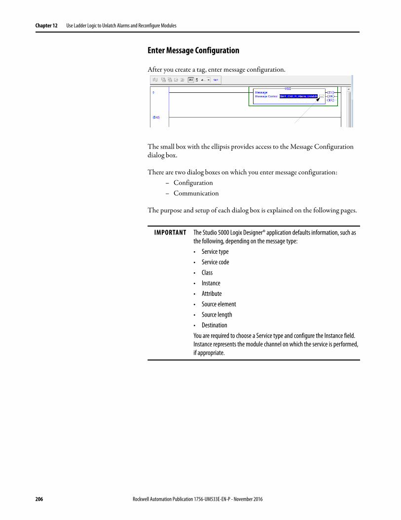
Chapter 12 Use Ladder Logic to Unlatch Alarms and Reconfigure Modules
Enter Message Configuration
After you create a tag, enter message configuration.
The small box with the ellipsis provides access to the Message Configuration dialog box.
There are two dialog boxes on which you enter message configuration:– Configuration– Communication
The purpose and setup of each dialog box is explained on the following pages.
IMPORTANT The Studio 5000 Logix Designer® application defaults information, such as the following, depending on the message type:• Service type• Service code• Class• Instance• Attribute• Source element• Source length• DestinationYou are required to choose a Service type and configure the Instance field. Instance represents the module channel on which the service is performed, if appropriate.
206 Rockwell Automation Publication 1756-UM533E-EN-P - November 2016
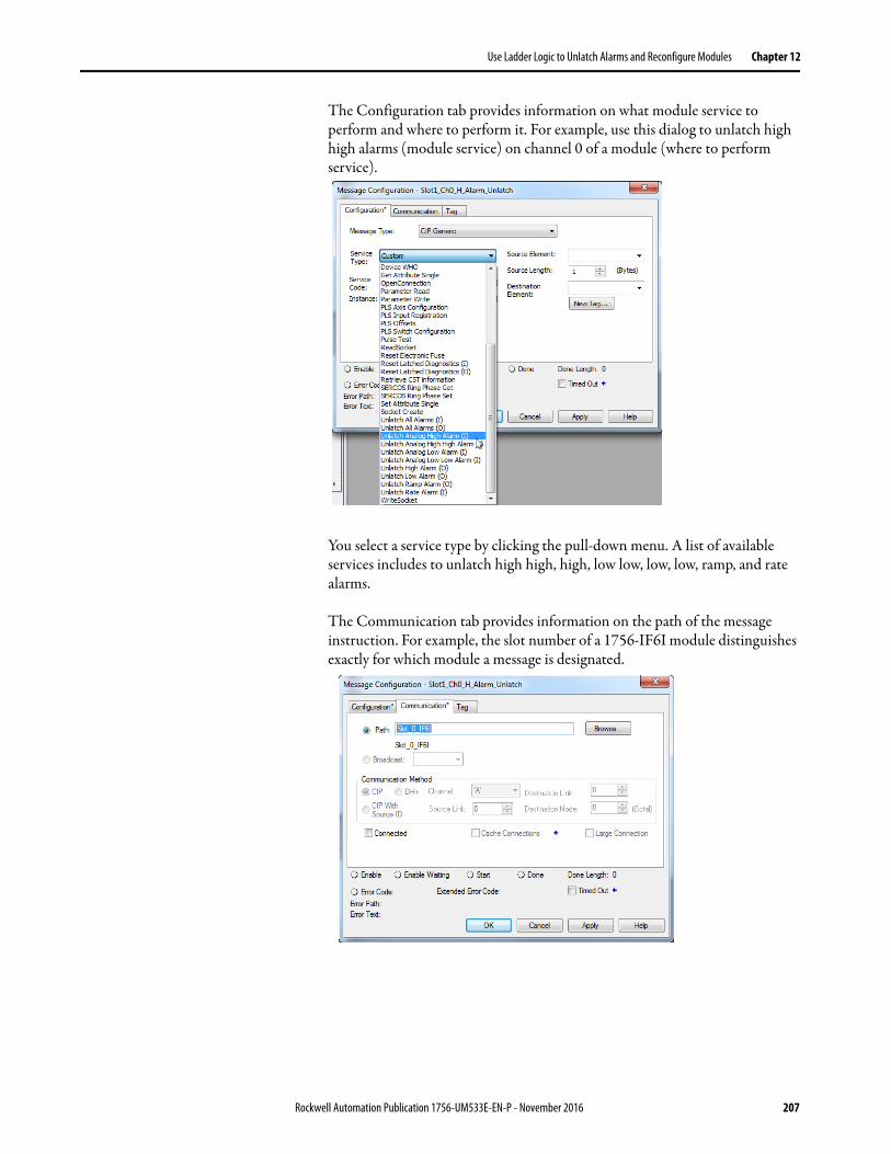
Use Ladder Logic to Unlatch Alarms and Reconfigure Modules Chapter 12
The Configuration tab provides information on what module service to perform and where to perform it. For example, use this dialog to unlatch high high alarms (module service) on channel 0 of a module (where to perform service).
You select a service type by clicking the pull-down menu. A list of available services includes to unlatch high high, high, low low, low, low, ramp, and rate alarms.
The Communication tab provides information on the path of the message instruction. For example, the slot number of a 1756-IF6I module distinguishes exactly for which module a message is designated.
Rockwell Automation Publication 1756-UM533E-EN-P - November 2016 207
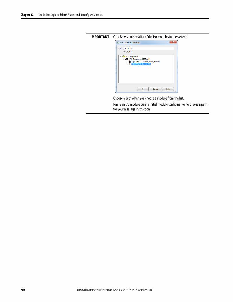
Chapter 12 Use Ladder Logic to Unlatch Alarms and Reconfigure Modules
IMPORTANT Click Browse to see a list of the I/O modules in the system.
Choose a path when you choose a module from the list.Name an I/O module during initial module configuration to choose a path for your message instruction.
208 Rockwell Automation Publication 1756-UM533E-EN-P - November 2016
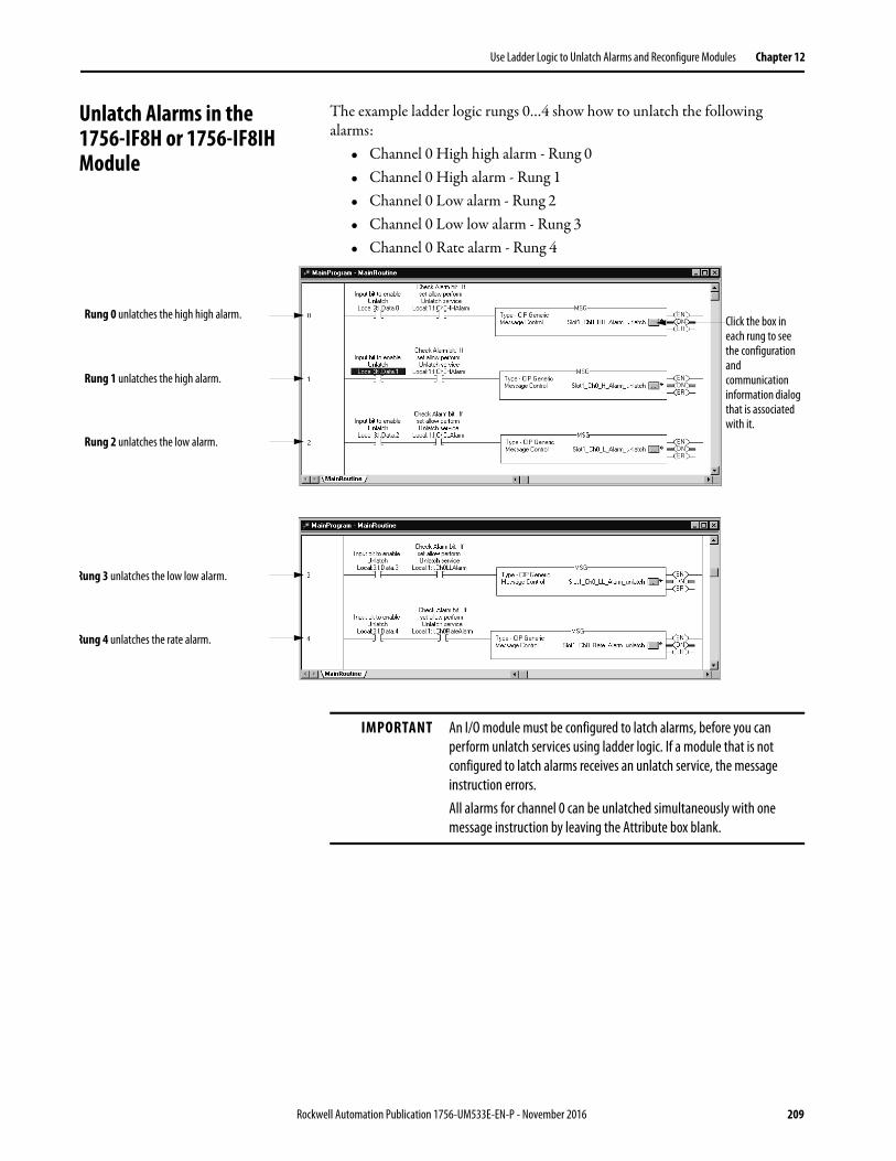
Use Ladder Logic to Unlatch Alarms and Reconfigure Modules Chapter 12
Unlatch Alarms in the 1756-IF8H or 1756-IF8IH Module
The example ladder logic rungs 0…4 show how to unlatch the following alarms:
• Channel 0 High high alarm - Rung 0• Channel 0 High alarm - Rung 1• Channel 0 Low alarm - Rung 2• Channel 0 Low low alarm - Rung 3• Channel 0 Rate alarm - Rung 4
Rung 0 unlatches the high high alarm.
Rung 1 unlatches the high alarm.
Rung 2 unlatches the low alarm.
Rung 3 unlatches the low low alarm.
Rung 4 unlatches the rate alarm.
Click the box in each rung to see the configuration and communication information dialog that is associated with it.
IMPORTANT An I/O module must be configured to latch alarms, before you can perform unlatch services using ladder logic. If a module that is not configured to latch alarms receives an unlatch service, the message instruction errors.All alarms for channel 0 can be unlatched simultaneously with one message instruction by leaving the Attribute box blank.
Rockwell Automation Publication 1756-UM533E-EN-P - November 2016 209
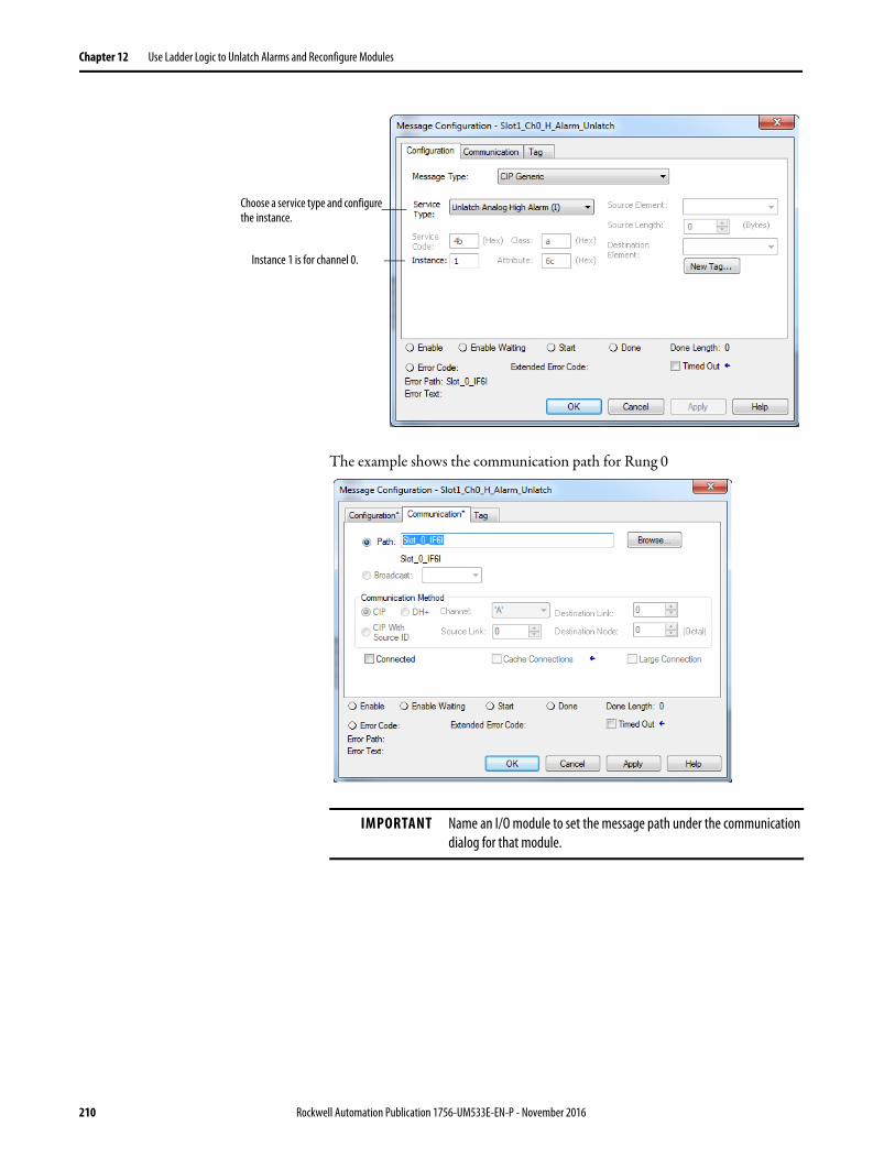
Chapter 12 Use Ladder Logic to Unlatch Alarms and Reconfigure Modules
The example shows the communication path for Rung 0
Choose a service type and configure the instance.
Instance 1 is for channel 0.
IMPORTANT Name an I/O module to set the message path under the communication dialog for that module.
210 Rockwell Automation Publication 1756-UM533E-EN-P - November 2016
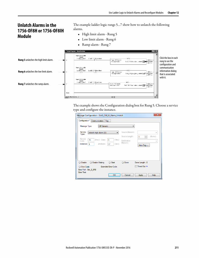
Use Ladder Logic to Unlatch Alarms and Reconfigure Modules Chapter 12
Unlatch Alarms in the1756-OF8H or 1756-OF8IH Module
The example ladder logic rungs 5…7 show how to unlatch the following alarms.
• High limit alarm - Rung 5• Low limit alarm - Rung 6• Ramp alarm - Rung 7
The example shows the Configuration dialog box for Rung 5. Choose a service type and configure the instance.
Rung 5 unlatches the high limit alarm.
Rung 6 unlatches the low limit alarm.
Rung 7 unlatches the ramp alarm.
Click the box in each rung to see the configuration and communication information dialog that is associated with it.
Rockwell Automation Publication 1756-UM533E-EN-P - November 2016 211
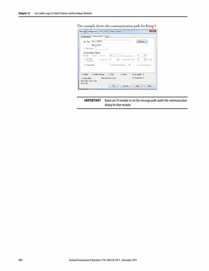
Chapter 12 Use Ladder Logic to Unlatch Alarms and Reconfigure Modules
The example shows the communication path for Rung 5.
IMPORTANT Name an I/O module to set the message path under the communication dialog for that module.
212 Rockwell Automation Publication 1756-UM533E-EN-P - November 2016
Use Ladder Logic to Unlatch Alarms and Reconfigure Modules Chapter 12
Reconfigure a Module It is sometimes advantageous to change the functional operation of a module in the ControlLogix system automatically via the user program rather than using the Logix Designer application to reconfigure a module. This way, changes in the process can dictate when the reconfiguration takes place rather than the user performing that function manually.
Use the steps in this example when reconfiguring a module via ladder logic.
1. Move new configuration parameters to the Configuration portion of the tag structure that is associated with the module.
2. Use a message instruction to send a Reconfigure Module service to the same module.
Before the new configuration parameters are sent to the module, make sure that their relationship to each other is in a format the module accepts (see Table 107 and Table 108).
The tables below list module parameters that you can change via ladder logic:
IMPORTANT Limit reconfiguration of analog modules via ladder to functions that involve the changing of values only. We do not recommend use of ladder logic to enable or disable features. Use the Logix Designer application to enable or disable these features.
Table 107 - Analog Input Module Parameters
Feature Restriction
High engineering value Must not be equal to low engineering value
Low engineering value Must not be equal to high engineering value
High-High alarm value Must be greater than or equal to high alarm value
High alarm value Must be greater than low alarm value
Low alarm value Must be less than high alarm value
Low-Low alarm value Must be less than or equal to low alarm value
Deadband Must be less than half of high alarm minus low alarm
Table 108 - Analog Output Module Parameters
Feature Restriction
High clamp value(1)
(1) The values for user-defined state at Fault or Program (set during initial configuration) must fall within the range of the High and Low Clamp values.
Must be greater than low clamp value
Low clamp value(1) Must be less than high clamp value
Rockwell Automation Publication 1756-UM533E-EN-P - November 2016 213

Chapter 12 Use Ladder Logic to Unlatch Alarms and Reconfigure Modules
Notes:
214 Rockwell Automation Publication 1756-UM533E-EN-P - November 2016
Chapter 13
Troubleshoot the Module
This chapter discusses these topics.
Use Module Indicators HART analog I/O modules have indicators to show module status. The illustration shows the indicators on a HART input module.
ControlLogix® modules use status indicators as shown in Table 109.
Topic Page
Use Module Indicators 215
General Troubleshooting Tips 216
Use the Logix Designer Application to Troubleshoot a Module 220
Module Configuration Errors 221
Remove the Module 224
ANALOG INPUT
CAL
OK
Table 109 - 1756-IF8H Status Indicators
OK Status Indicator State CAL Status Indicator State
Module State Notes
Red steady Green steady Power on/initialization Initial state. Status indicator power-on test
Green blinking Off Normal operation The module has passed internal diagnostics, but is not currently performing connected communication
Green steady Off Normal operation Normal run mode; inputs being multicast
Green blinking (if not connected)Green steady (if connected)
Green blinking fast with no pauses
Calibration Calibration in progress
Red blinking Off Lost connection Communication between controller and module has been lost (timed out)
Red blinking Green steady Firmware update Firmware update in progress
Red steady Off Fault Hardware fault; check to see if module must be replaced
Off Off Abnormal Hardware fault
Orange Off Abnormal Hardware fault
Red steady Green blinking with pauses Fault Module fault - see blink codes(1)
(1) Under fault conditions the module specifies the fault via the CAL status indicator blink code as described in Table 110.
Rockwell Automation Publication 1756-UM533E-EN-P - November 2016 215
Chapter 13 Troubleshoot the Module
Table 110 shows CAL indicator blink codes.
To see fault status, click the Module Info tab on the Module Properties dialog box in the Studio 5000 Logix Designer® application. A channel fault, such as wire off, is displayed as a ‘Recoverable’ minor fault.
General Troubleshooting Tips When troubleshooting, consider these typical problems:• Check the Enable HART box in the Logix Designer application if you
want any HART communication access to the channel. This configuration is required for communication from asset management and pass-through messages.
• Choose an Input Tag Data Format that includes HART if you want to use the secondary process variables and device health information in your controller or display it in FactoryTalk® View software.
• On the 1756-IF8H module, put a jumper wire from IN0- to I-RTN-0 if you use 4…20 mA devices.
• On the 1756-IF8H 1756-IF16H, and 1756-IF16IH modules, do not tie RTN-X together if you are mixing 2-wire and 4-wire HART devices on the same module.
• Channel buttons in the Logix Designer application apply only to the currently displayed dialog.
• From RSLinx software, if you click RSWho and see 1756-Module, install the EDS file from the Rockwell Automation Product Compatibility and Download Center. Go to http://www.rockwellautomation.com/support/ and click the Product Compatibility and Download Center link under Resources.
Table 110 - CAL Indicator Blink Codes
If OK Is And CAL Is Condition Recommended ActionRed Flashing Green Firmware Download in Process Wait for the download to complete.Red 3 Blinks ASIC EEPROM CRC is not valid Nonrecoverable - send the module in for repair.Red 5 Blinks Boot code section has failed the CRC check Nonrecoverable - send the module in for repairRed 6 Blinks Application code section has failed the CRC
check.Try reprogramming the module firmware. If condition persists, send the module in for repair.
Red 9 Blinks Stored calibration data is corrupt and cannot be read. No calibration is applied to input data.
Major nonrecoverable - send the module in for repair
Red 10 Blinks Module firmware watchdog timer has timed out.
Try resetting the module. If the condition persists, send the module in for repair.
Red 13 blinks HART processor hardware fault. A communication error has occurred between the main CPU and HART CPU.
Nonrecoverable - send the module in for repair.
Red 14 blinks HART CPU firmware fault. The HART CPU detected a fault and communicated it to the main CPU.
Nonrecoverable - send the module in for repair.
Channel buttons apply to the current dialog.
216 Rockwell Automation Publication 1756-UM533E-EN-P - November 2016
Troubleshoot the Module Chapter 13
• In some versions of the Logix Designer application or RSLogix 5000® software, the profiles for the ControlLogix HART analog I/O modules are not included.Go to http://www.rockwellautomation.com/support/ and click the Product Compatibility and Download Center link under Resources to find and download the Add-on Profile.
• In RSLogix 5000 software, version 15 and later or the Logix Designer application, with an error about ControlNet Attribute, use Scheduled Connections, or shutdown and restart the RSLogix 5000 software or the Logix Designer application.
• If you cannot find HART data, look in subfield Local:7:I.HART at bottom of the tag or in chassis:7:I.Chxx.PV for data that are grouped by channel.
When troubleshooting, consider these more obscure problems.• The same device appears to be connected to every channel because a
wiring problem causes signals to get connected across channels. In some cases, loose IRET wires cause the path to ground to flow through other channels.
• If Keep HART Replies for XX seconds is set small – less than 5 seconds, the module throws away replies before you get a chance to retrieve them. This action affects both MSG pass-through messages and PC-based asset management, such as FieldCare software. We recommend 15 seconds for this parameter.
• Be sure that you have a HART device. Foundation Fieldbus, PROFIBUS PA, and plain 4…20 devices look the same on the outside and power up OK.
• Write protect jumper is not reported correctly. This condition gets refreshed only if the device reports it changed. E&H and Rosemount devices do not. Disable HART then re-enable HART to get it refreshed on the HART Device Info dialog.
For pass-through message troubleshooting issues, use these tips:• Check module-specific online help.• Copy the Handle to the Query.• Check sizes of MSG and HART command.• Check packing, alignment, and byte ordering.• Use MsgReady.• Name tags and UDTs similarly to group them together for convenience.
For example, start the related tags with the same prefix.• Check .ER and Status.
Rockwell Automation Publication 1756-UM533E-EN-P - November 2016 217
Chapter 13 Troubleshoot the Module
For input tag troubleshooting, use these tips:• Local:7:I.Ch0Fault – if 1, suspect wiring/instrument problem.• Local:7:I.Ch0HARTFault – if 1, check Local:7:C.HARTEn (Enable
HART).• Local:7:I.HART.Ch0DeviceStatus.Init – HART is enabled, but still
trying to get a response from device.• Local:7:I.HART.Ch0DeviceStatus.Fail – HART is disabled, or
not responding.• Local:7:I.HART.Ch0DeviceStatus.CurrentFault – the measured mA
current doesn’t match what is reported via HART. A recent change in value can cause this condition. It is intended to indicate a current leak, such as water in the conduit.
• Local:7:I.HART.Ch0DeviceStatus.ResponseCode – if negative, there is some communication problem. If positive, device is indicating some problem with the command. 16#40 means command not supported.
• Local:7:I.HART.Ch0DeviceStatus.FieldDeviceStatus – 0 is good; refer to Help or see the Table 117 on page 229 for more information.
• Local:7:I.HART.Ch0PVStatus – 16#C0 is good. 0 is bad. This condition could indicate a communication problem or something wrong with the device. For example, with SVStatus, this condition could mean that the device does not support multiple measurements.
218 Rockwell Automation Publication 1756-UM533E-EN-P - November 2016
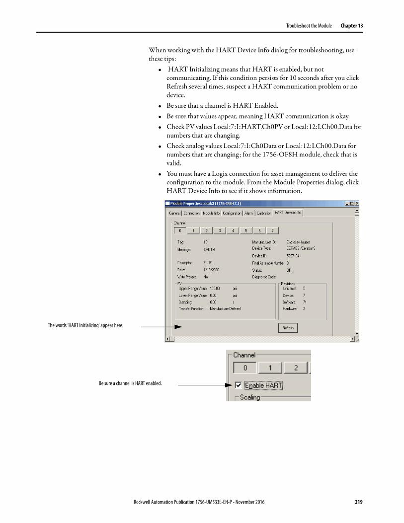
Troubleshoot the Module Chapter 13
When working with the HART Device Info dialog for troubleshooting, use these tips:
• HART Initializing means that HART is enabled, but not communicating. If this condition persists for 10 seconds after you click Refresh several times, suspect a HART communication problem or no device.
• Be sure that a channel is HART Enabled.• Be sure that values appear, meaning HART communication is okay.• Check PV values Local:7:I:HART.Ch0PV or Local:12:I.Ch00.Data for
numbers that are changing.• Check analog values Local:7:I:Ch0Data or Local:12:I.Ch00.Data for
numbers that are changing; for the 1756-OF8H module, check that is valid.
• You must have a Logix connection for asset management to deliver the configuration to the module. From the Module Properties dialog, click HART Device Info to see if it shows information.
The words ‘HART Initializing’ appear here.
Be sure a channel is HART enabled.
Rockwell Automation Publication 1756-UM533E-EN-P - November 2016 219
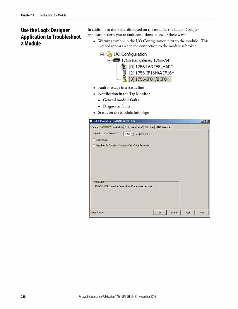
Chapter 13 Troubleshoot the Module
Use the Logix Designer Application to Troubleshoot a Module
In addition to the status displayed on the module, the Logix Designer application alerts you to fault conditions in one of these ways:
• Warning symbol in the I/O Configuration next to the module - This symbol appears when the connection to the module is broken
• Fault message in a status line• Notification in the Tag Monitor
• General module faults• Diagnostic faults
• Status on the Module Info Page
220 Rockwell Automation Publication 1756-UM533E-EN-P - November 2016
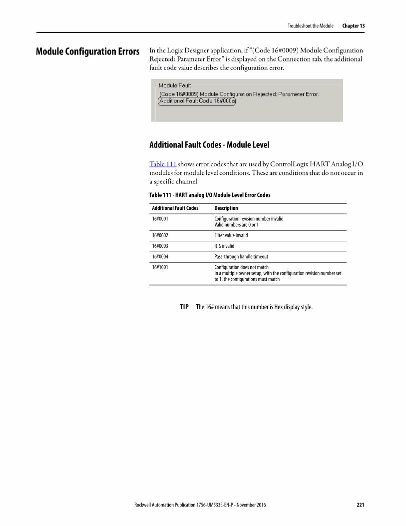
Troubleshoot the Module Chapter 13
Module Configuration Errors In the Logix Designer application, if “(Code 16#0009) Module Configuration Rejected: Parameter Error” is displayed on the Connection tab, the additional fault code value describes the configuration error.
Additional Fault Codes - Module Level
Table 111 shows error codes that are used by ControlLogix HART Analog I/O modules for module level conditions. These are conditions that do not occur in a specific channel.
Table 111 - HART analog I/O Module Level Error Codes
Additional Fault Codes Description
16#0001 Configuration revision number invalidValid numbers are 0 or 1
16#0002 Filter value invalid
16#0003 RTS invalid
16#0004 Pass-through handle timeout
16#1001 Configuration does not matchIn a multiple owner setup, with the configuration revision number set to 1, the configurations must match
TIP The 16# means that this number is Hex display style.
Rockwell Automation Publication 1756-UM533E-EN-P - November 2016 221
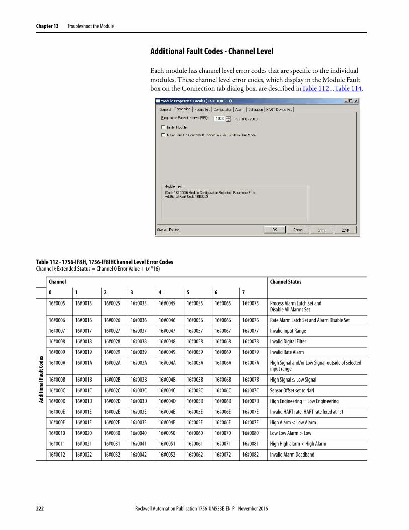
Chapter 13 Troubleshoot the Module
Additional Fault Codes - Channel Level
Each module has channel level error codes that are specific to the individual modules. These channel level error codes, which display in the Module Fault box on the Connection tab dialog box, are described inTable 112…Table 114.
Table 112 - 1756-IF8H, 1756-IF8IHChannel Level Error CodesChannel x Extended Status = Channel 0 Error Value + (x *16)
Channel Channel Status
0 1 2 3 4 5 6 7
Addi
tiona
l Fau
lt Co
des
16#0005 16#0015 16#0025 16#0035 16#0045 16#0055 16#0065 16#0075 Process Alarm Latch Set and Disable All Alarms Set
16#0006 16#0016 16#0026 16#0036 16#0046 16#0056 16#0066 16#0076 Rate Alarm Latch Set and Alarm Disable Set
16#0007 16#0017 16#0027 16#0037 16#0047 16#0057 16#0067 16#0077 Invalid Input Range
16#0008 16#0018 16#0028 16#0038 16#0048 16#0058 16#0068 16#0078 Invalid Digital Filter
16#0009 16#0019 16#0029 16#0039 16#0049 16#0059 16#0069 16#0079 Invalid Rate Alarm
16#000A 16#001A 16#002A 16#003A 16#004A 16#005A 16#006A 16#007A High Signal and/or Low Signal outside of selected input range
16#000B 16#001B 16#002B 16#003B 16#004B 16#005B 16#006B 16#007B High Signal Low Signal
16#000C 16#001C 16#002C 16#003C 16#004C 16#005C 16#006C 16#007C Sensor Offset set to NaN
16#000D 16#001D 16#002D 16#003D 16#004D 16#005D 16#006D 16#007D High Engineering = Low Engineering
16#000E 16#001E 16#002E 16#003E 16#004E 16#005E 16#006E 16#007E Invalid HART rate, HART rate fixed at 1:1
16#000F 16#001F 16#002F 16#003F 16#004F 16#005F 16#006F 16#007F High Alarm < Low Alarm
16#0010 16#0020 16#0030 16#0040 16#0050 16#0060 16#0070 16#0080 Low Low Alarm > Low
16#0011 16#0021 16#0031 16#0041 16#0051 16#0061 16#0071 16#0081 High High alarm < High Alarm
16#0012 16#0022 16#0032 16#0042 16#0052 16#0062 16#0072 16#0082 Invalid Alarm Deadband
222 Rockwell Automation Publication 1756-UM533E-EN-P - November 2016
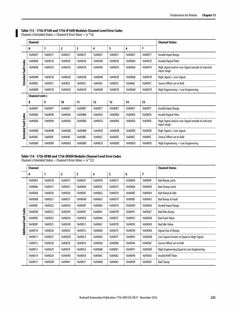
Troubleshoot the Module Chapter 13
Table 113 - 1756-IF16H and 1756-IF16IH Modules Channel Level Error Codes Channel x Extended Status = Channel 0 Error Value + (x *16)
Channel Channel Status
0 1 2 3 4 5 6 7
Exte
nded
Faul
t Cod
es
16#0007 16#0017 16#0027 16#0037 16#0047 16#0057 16#0067 16#0077 Invalid Input Range
16#0008 16#0018 16#0028 16#0038 16#0048 16#0058 16#0068 16#0078 Invalid Digital Filter
16#000A 16#001A 16#002A 16#003A 16#004A 16#005A 16#006A 16#007A High Signal and/or Low Signal outside of selected input range
16#000B 16#001B 16#002B 16#003B 16#004B 16#005B 16#006B 16#007B High Signal Low Signal
16#000C 16#001C 16#002C 16#003C 16#004C 16#005C 16#006C 16#007C Sensor Offset set to NaN
16#000D 16#001D 16#002D 16#003D 16#004D 16#005D 16#006D 16#007D High Engineering = Low Engineering
Channel (cont.)
8 9 10 11 12 13 14 15
Exte
nded
Faul
t Cod
es
16#0087 16#0097 16#00A7 16#00B7 16#00C7 16#00D7 16#00E7 16#00F7 Invalid Input Range
16#0088 16#0098 16#00A8 16#00B8 16#00C8 16#00D8 16#00E8 16#00F8 Invalid Digital Filter
16#008A 16#009A 16#00AA 16#00BA 16#00CA 16#00DA 16#00EA 16#00FA High Signal and/or Low Signal outside of selected input range
16#008B 16#009B 16#00AB 16#00BB 16#00CB 16#00DB 16#00EB 16#00FB High Signal Low Signal
16#008C 16#009C 16#00AC 16#00BC 16#00CC 16#00DC 16#00EC 16#00FC Sensor Offset set to NaN
16#008D 16#009D 16#00AD 16#00BD 16#00CD 16#00DD 16#00ED 16#00FD High Engineering = Low Engineering
Table 114 - 1756-OF8H and 1756-OF8IH Modules Channel Level Error CodesChannel x Extended Status = Channel 0 Error Value + (x *22)
Channel Channel Status
0 1 2 3 4 5 6 7
Addi
tiona
l Fau
lt Co
des
16#0005 16#001B 16#0031 16#0047 16#005D 16#0073 16#0089 16#009F Bad Ramp Latch
16#0006 16#001C 16#0032 16#0048 16#005E 16#0074 16#008A 16#00A0 Bad Clamp Latch
16#000A 16#0020 16#0036 16#004C 16#0062 16#0078 16#008E 16#00A4 Bad Ramp to Idle
16#000B 16#0021 16#0037 16#004D 16#0063 16#0079 16#008F 16#00A5 Bad Ramp to Fault
16#000C 16#0022 16#0038 16#004E 16#0064 16#007A 16#0090 16#00A6 Invalid Input Range
16#000D 16#0023 16#0039 16#004F 16#0065 16#007B 16#0091 16#00A7 Bad Max Ramp
16#000E 16#0024 16#003A 16#0050 16#0066 16#007C 16#0092 16#00A8 Bad Fault Value
16#000F 16#0025 16#003B 16#0051 16#0067 16#007D 16#0093 16#00A9 Bad Idle Value
16#0010 16#0026 16#003C 16#0052 16#0068 16#007E 16#0094 16#00AA Signal Out of Range
16#0011 16#0027 16#003D 16#0053 16#0069 16#007F 16#0095 16#00AB Low Signal Greater or Equal to High Signal
16#0012 16#0028 16#003E 16#0054 16#006A 16#0080 16#0096 16#00AC Sensor Offset set to NaN
16#0013 16#0029 16#003F 16#0055 16#006B 16#0081 16#0097 16#00AD High Engineering Equal to Low Engineering
16#0014 16#002A 16#0040 16#0056 16#006C 16#0082 16#0098 16#00AE Invalid HART Rate
16#0015 16#002B 16#0041 16#0057 16#006D 16#0083 16#0099 16#00AF Bad Clamp
Rockwell Automation Publication 1756-UM533E-EN-P - November 2016 223
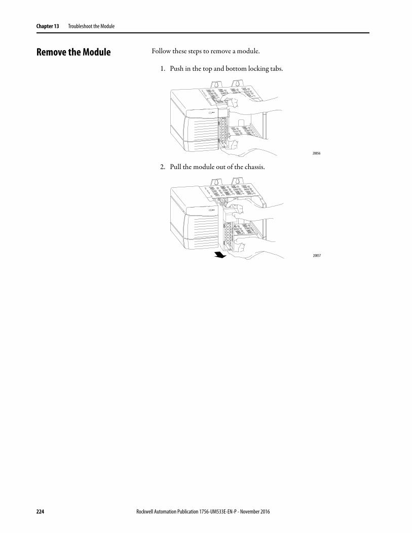
Chapter 13 Troubleshoot the Module
Remove the Module Follow these steps to remove a module.
1. Push in the top and bottom locking tabs.
2. Pull the module out of the chassis.
20856
20857
224 Rockwell Automation Publication 1756-UM533E-EN-P - November 2016
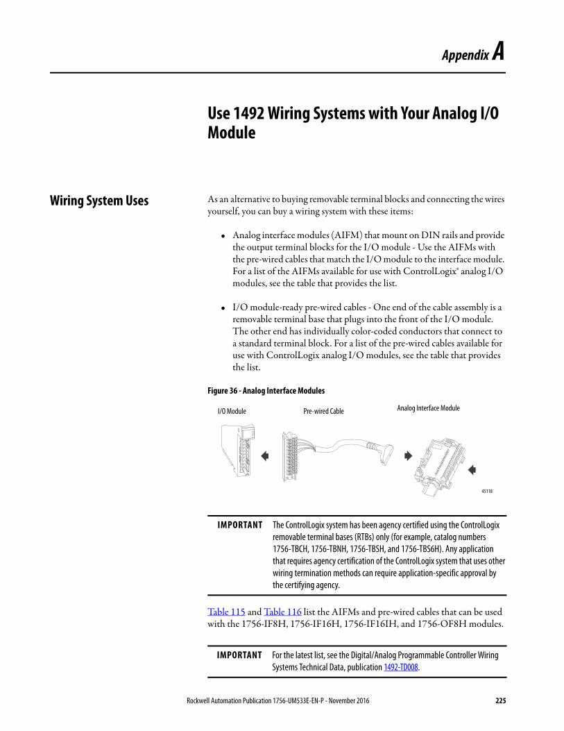
Appendix A
Use 1492 Wiring Systems with Your Analog I/O Module
Wiring System Uses As an alternative to buying removable terminal blocks and connecting the wires yourself, you can buy a wiring system with these items:
• Analog interface modules (AIFM) that mount on DIN rails and provide the output terminal blocks for the I/O module - Use the AIFMs with the pre-wired cables that match the I/O module to the interface module. For a list of the AIFMs available for use with ControlLogix® analog I/O modules, see the table that provides the list.
• I/O module-ready pre-wired cables - One end of the cable assembly is a removable terminal base that plugs into the front of the I/O module. The other end has individually color-coded conductors that connect to a standard terminal block. For a list of the pre-wired cables available for use with ControlLogix analog I/O modules, see the table that provides the list.
Figure 36 - Analog Interface Modules
Table 115 and Table 116 list the AIFMs and pre-wired cables that can be used with the 1756-IF8H, 1756-IF16H, 1756-IF16IH, and 1756-OF8H modules.
IMPORTANT The ControlLogix system has been agency certified using the ControlLogix removable terminal bases (RTBs) only (for example, catalog numbers 1756-TBCH, 1756-TBNH, 1756-TBSH, and 1756-TBS6H). Any application that requires agency certification of the ControlLogix system that uses other wiring termination methods can require application-specific approval by the certifying agency.
IMPORTANT For the latest list, see the Digital/Analog Programmable Controller Wiring Systems Technical Data, publication 1492-TD008.
I/O Module Pre-wired Cable Analog Interface Module
45118
Rockwell Automation Publication 1756-UM533E-EN-P - November 2016 225
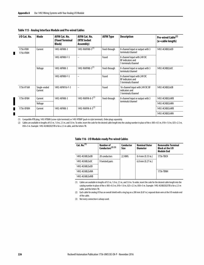
Appendix A Use 1492 Wiring Systems with Your Analog I/O Module
Table 115 - Analog Interface Module and Pre-wired Cables
I/O Cat. No. Mode AIFM Cat. No.(Fixed Terminal Block)
AIFM Cat. No. (RTB Socket Assembly)
AIFM Type Description Pre-wired Cable(2)
(x=cable length)
1756-IF8H1756-IF8IH
Current 1492-AIFM8-3 1492-RAIFM8-3(1) Feed-through 8-channel input or output with 3 terminals/channel
1492-ACABLExUD
1492-AIFM8-F-5 – Fused 8-channel input with 24V DCBF indicators and5 terminals/channel
Voltage 1492-AIFM8-3 1492-RAIFM8-3(1) Feed-through 8-channel input or output with 3 terminals/channel
1492-ACABLExUC
1492-AIFM8-F-5 – Fused 8-channel input with 24V DCBF indicators and5 terminals/channel
1756-IF16H Single-ended Current
1492-AIFM16-F-3 – Fused 16-channel input with 24V DC BF indicators and3 terminals/channel
1492-ACABLExUB
1756-OF8H Current 1492-AIFM8-3 1492-RAIFM-8-3(1) Feed-through 8-channel input or output with 3 terminals/channel
1492-ACABLExWB
Voltage 1492-ACABLExWA
1756-OF8IH Current 1492-AIFM8-3 1492-RAIFM-8-3(1) 1492-ACABLExWB
1492-ACABLExWA
(1) Compatible RTB plug; 1492-RTB8N (screw-style terminals) or 1492-RTB8P (push-in style terminals). Order plugs separately.(2) Cables are available in lengths of 0.5 m, 1.0 m, 2.5 m, and 5.0 m. To order, insert the code for the desired cable length into the catalog number in place of the x: 005=0.5 m, 010=1.0 m, 025=2.5 m,
050=5 m. Example: 1492-ACABLE025TB is for a 2.5 m cable, and the letters TB.
Table 116 - I/O Module-ready Pre-wired Cables
Cat. No.(1)
(1) Cables are available in lengths of 0.5 m, 1.0 m, 2.5 m, and 5.0 m. To order, insert the code for the desired cable length into the catalog number in place of the x: 005=0.5 m, 010=1.0 m, 025=2.5 m, 050=5 m. Example: 1492-ACABLE025TB is for a 2.5 m cable, and the letters TB.
Number of Conductors(2) (3)
(2) Each cable for analog I/O has an overall shield with a ring lug on a 200 mm (8.87 in.) exposed drain wire at the I/O module end of the cable.
(3) Not every connection is always used.
Conductor Size
Nominal Outer Diameter
Removable Terminal Block at the I/O Module End
1492-ACABLExUB 20 conductors 22 AWG 8.4 mm (0.33 in.) 1756-TBCH
1492-ACABLExUC 9 twisted pairs 6.8 mm (0.27 in.)
1492-ACABLExUD
1492-ACABLExWA 1756-TBNH
1492-ACABLExWB
226 Rockwell Automation Publication 1756-UM533E-EN-P - November 2016
Appendix B
Additional HART Protocol Information
This appendix discusses these topics.
This appendix describes the HART protocol and provides references for additional information about the protocol. Consult the HART protocol specification and vendor-provided documentation for specifics on HART commands.
This appendix provides the following:• HART protocol background information• Common practice command sets• Extended command sets• References to additional information
HART Field Communication Protocol is widely accepted in the industry as the standard for digitally enhanced 4…20mA communication with smart field instruments. The HART Protocol message structure, command set, and status are discussed in this appendix.
The HART command set is organized into these groups and provides read and write access to a wide array of information available in smart field instruments:
• Universal commands provide access to information that is useful in normal plant operation such as the instrument manufacturer, model, tag, serial number, descriptor, range limits, and process variables. All HART devices must implement universal commands.
• Common practice commands provide access to functions that many devices can carry out.
• Device-specific commands provide access to functions that can be unique to a particular device.
Topic Page
Message Structure 228
Response Code and Field Device Status 229
HART PV, SV, TV, and FV Status 236
Rockwell Automation Publication 1756-UM533E-EN-P - November 2016 227

Appendix B Additional HART Protocol Information
Message Structure Read this section for a description of transaction procedure, character coding, and message structure of the HART protocol. These correspond to layer 2 (data-link layer) of the OSI protocol reference model.
Master-slave Operation
HART is a master-slave protocol. This means that the master originates each message transaction; the slave (field) device replies when it receives a command message that is addressed to it. The reply from the slave device acknowledges that the command was received and can contain data that the master requested.
Multiple Master Operation
The HART protocol provides for two active masters in a system: one primary and one secondary. The two masters have different addresses. Each can positively identify replies to its own command messages. The 1756-IF8H, 1756-IF8IH, 1756-IF16H, 1756-IF16IH, 1756-OF8H, or 1756-OF8IH module acts as primary master. A secondary master, such as a handheld configuration device, can also be connected.
Transaction Procedure
HART is a half-duplex protocol. After completion of each message, the FSK carrier signal must be switched off to let the other station transmit. The carrier control timing rules state the following:
• Not to turn on the carrier more than 5 bit times before the start of the message (the preamble)
• Not to turn off more than 5 bit times after the end of the last byte of the message (the checksum)
The master is responsible for controlling message transactions. If there is no reply to a command within the expected time, the master retries the message. After a few retries, the master aborts the transaction, because presumably the slave device or the communication link has failed.
After each transaction is completed, the master pauses for a short time before sending another command, to provide an opportunity for the other master to break in if it wishes. This way, two masters (if they are present) take turns communicating with the slave devices. Typical message lengths and delays allow two transactions per second.
228 Rockwell Automation Publication 1756-UM533E-EN-P - November 2016
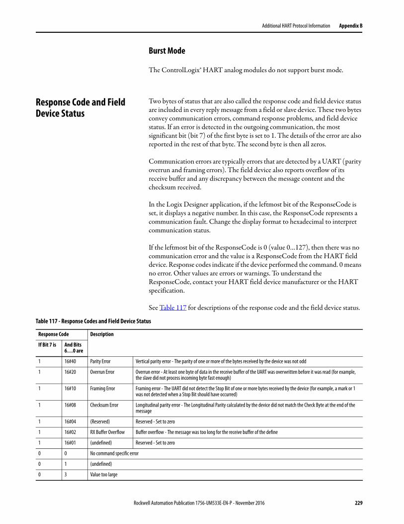
Additional HART Protocol Information Appendix B
Burst Mode
The ControlLogix® HART analog modules do not support burst mode.
Response Code and Field Device Status
Two bytes of status that are also called the response code and field device status are included in every reply message from a field or slave device. These two bytes convey communication errors, command response problems, and field device status. If an error is detected in the outgoing communication, the most significant bit (bit 7) of the first byte is set to 1. The details of the error are also reported in the rest of that byte. The second byte is then all zeros.
Communication errors are typically errors that are detected by a UART (parity overrun and framing errors). The field device also reports overflow of its receive buffer and any discrepancy between the message content and the checksum received.
In the Logix Designer application, if the leftmost bit of the ResponseCode is set, it displays a negative number. In this case, the ResponseCode represents a communication fault. Change the display format to hexadecimal to interpret communication status.
If the leftmost bit of the ResponseCode is 0 (value 0…127), then there was no communication error and the value is a ResponseCode from the HART field device. Response codes indicate if the device performed the command. 0 means no error. Other values are errors or warnings. To understand the ResponseCode, contact your HART field device manufacturer or the HART specification.
See Table 117 for descriptions of the response code and the field device status.
Table 117 - Response Codes and Field Device Status
Response Code Description
If Bit 7 is And Bits 6…0 are
1 16#40 Parity Error Vertical parity error - The parity of one or more of the bytes received by the device was not odd
1 16#20 Overrun Error Overrun error - At least one byte of data in the receive buffer of the UART was overwritten before it was read (for example, the slave did not process incoming byte fast enough)
1 16#10 Framing Error Framing error - The UART did not detect the Stop Bit of one or more bytes received by the device (for example, a mark or 1 was not detected when a Stop Bit should have occurred)
1 16#08 Checksum Error Longitudinal parity error - The Longitudinal Parity calculated by the device did not match the Check Byte at the end of the message
1 16#04 (Reserved) Reserved - Set to zero
1 16#02 RX Buffer Overflow Buffer overflow - The message was too long for the receive buffer of the define
1 16#01 (undefined) Reserved - Set to zero
0 0 No command specific error
0 1 (undefined)
0 3 Value too large
Rockwell Automation Publication 1756-UM533E-EN-P - November 2016 229
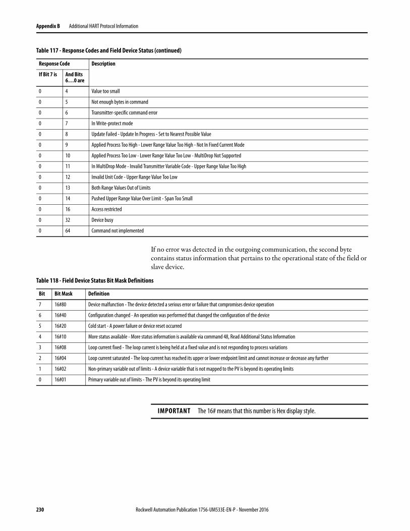
Appendix B Additional HART Protocol Information
If no error was detected in the outgoing communication, the second byte contains status information that pertains to the operational state of the field or slave device.
0 4 Value too small
0 5 Not enough bytes in command
0 6 Transmitter-specific command error
0 7 In Write-protect mode
0 8 Update Failed - Update In Progress - Set to Nearest Possible Value
0 9 Applied Process Too High - Lower Range Value Too High - Not In Fixed Current Mode
0 10 Applied Process Too Low - Lower Range Value Too Low - MultiDrop Not Supported
0 11 In MultiDrop Mode - Invalid Transmitter Variable Code - Upper Range Value Too High
0 12 Invalid Unit Code - Upper Range Value Too Low
0 13 Both Range Values Out of Limits
0 14 Pushed Upper Range Value Over Limit - Span Too Small
0 16 Access restricted
0 32 Device busy
0 64 Command not implemented
Table 117 - Response Codes and Field Device Status (continued)
Response Code Description
If Bit 7 is And Bits 6…0 are
Table 118 - Field Device Status Bit Mask Definitions
Bit Bit Mask Definition
7 16#80 Device malfunction - The device detected a serious error or failure that compromises device operation
6 16#40 Configuration changed - An operation was performed that changed the configuration of the device
5 16#20 Cold start - A power failure or device reset occurred
4 16#10 More status available - More status information is available via command 48, Read Additional Status Information
3 16#08 Loop current fixed - The loop current is being held at a fixed value and is not responding to process variations
2 16#04 Loop current saturated - The loop current has reached its upper or lower endpoint limit and cannot increase or decrease any further
1 16#02 Non-primary variable out of limits - A device variable that is not mapped to the PV is beyond its operating limits
0 16#01 Primary variable out of limits - The PV is beyond its operating limit
IMPORTANT The 16# means that this number is Hex display style.
230 Rockwell Automation Publication 1756-UM533E-EN-P - November 2016
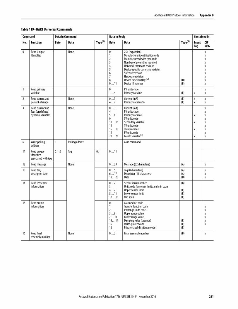
Additional HART Protocol Information Appendix B
Table 119 - HART Universal Commands
Command Data in Command Data in Reply Contained in
No. Function Byte Data Type(1) Byte Data Type(1) Input Tag
CIP MSG
0 Read Unique Identified
None 0123456789…11
254 (expansion)Manufacturer identification codeManufacturer device type codeNumber of preambles requiredUniversal command revisionDevice-specific command revisionSoftware versionHardware revisionDevice function flags(2)
Device ID number(H)(B)
xxxxxxxxxx
1 Read primary variable
01…4
PV units codePrimary variable (F) x
xx
2 Read current and percent of range
None 0…34…7
Current (mA)Primary variable %
(F)(F)
xx
xx
3 Read current and four (predefined) dynamic variables
None 0…345…8910…131415…181920…23
Current (mA)PV units codePrimary variableSV units codeSecondary variableTV units codeThird variableFV units codeFourth variable(3)
x
x
x
x
xxxxxxxxx
6 Write polling address
0 Polling address As in command
11 Read unique identifier associated with tag
0…5 Tag (A) 0…11
12 Read message None 0…23 Message (32 characters) (A) x
13 Read tag, descriptor, date
0…56…1718…20
Tag (8 characters)Descriptor (16 characters)Date
(A)(A)(D)
xxx
14 Read PV sensor information
0…234…78…1112…15
Sensor serial numberUnits code for sensor limits and min spanUpper sensor limitLower sensor limitMin span
(B)
(F)(F)(F)
15 Read output information
0123…67…1011…141516
Alarm select codeTransfer function codePV/range units codeUpper range valueLower range valueDamping value (seconds)Write-protect codePrivate-label distributor code
(F)(F)(F)
xxxxxx
16 Read final assembly number
None 0…2 Final assembly number (B) x
Rockwell Automation Publication 1756-UM533E-EN-P - November 2016 231
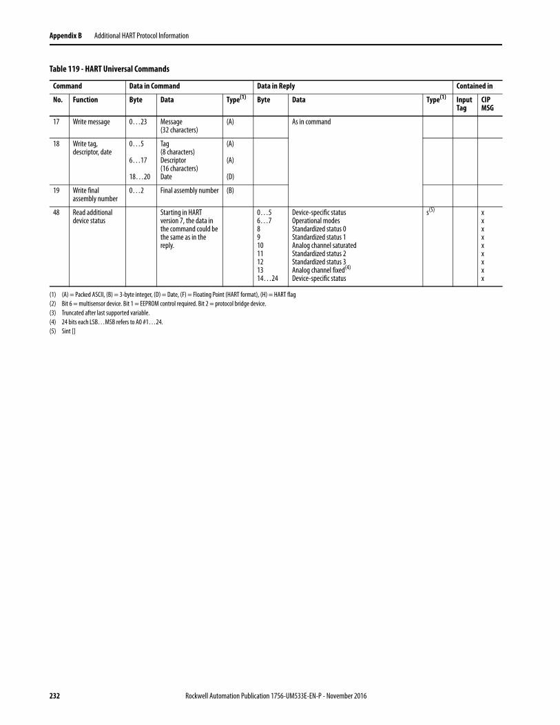
Appendix B Additional HART Protocol Information
17 Write message 0…23 Message (32 characters)
(A) As in command
18 Write tag, descriptor, date
0…5
6…17
18…20
Tag (8 characters)Descriptor(16 characters)Date
(A)
(A)
(D)
19 Write final assembly number
0…2 Final assembly number (B)
48 Read additional device status
Starting in HART version 7, the data in the command could be the same as in the reply.
0…56…7891011121314…24
Device-specific statusOperational modesStandardized status 0Standardized status 1Analog channel saturatedStandardized status 2Standardized status 3Analog channel fixed(4)
Device-specific status
s(5) xxxxxxxxx
(1) (A) = Packed ASCII, (B) = 3-byte integer, (D) = Date, (F) = Floating Point (HART format), (H) = HART flag(2) Bit 6 = multisensor device. Bit 1 = EEPROM control required. Bit 2 = protocol bridge device.(3) Truncated after last supported variable.(4) 24 bits each LSB…MSB refers to A0 #1…24.(5) Sint []
Table 119 - HART Universal Commands
Command Data in Command Data in Reply Contained in
No. Function Byte Data Type(1) Byte Data Type(1) Input Tag
CIP MSG
232 Rockwell Automation Publication 1756-UM533E-EN-P - November 2016
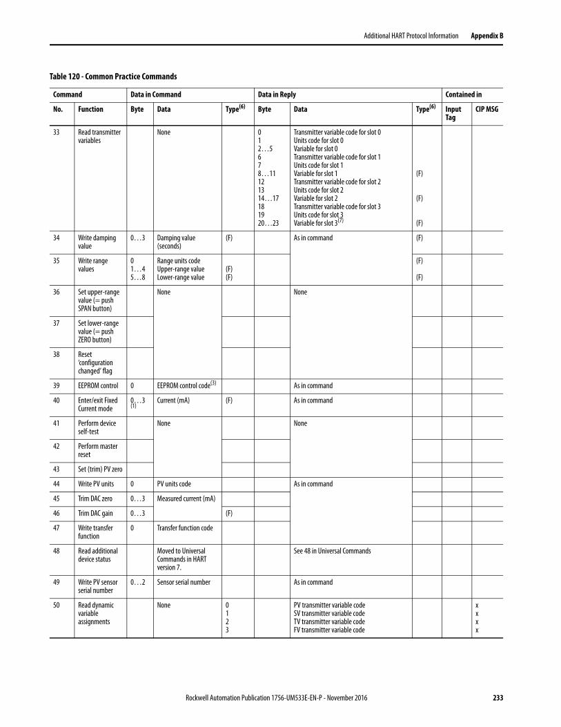
Additional HART Protocol Information Appendix B
Table 120 - Common Practice Commands
Command Data in Command Data in Reply Contained in
No. Function Byte Data Type(6) Byte Data Type(6) Input Tag
CIP MSG
33 Read transmitter variables
None 012…5678…11121314…17181920…23
Transmitter variable code for slot 0Units code for slot 0Variable for slot 0Transmitter variable code for slot 1Units code for slot 1Variable for slot 1Transmitter variable code for slot 2Units code for slot 2Variable for slot 2Transmitter variable code for slot 3Units code for slot 3Variable for slot 3(7)
(F)
(F)
(F)
34 Write damping value
0…3 Damping value (seconds)
(F) As in command (F)
35 Write range values
01…45…8
Range units codeUpper-range valueLower-range value
(F)(F)
(F)
(F)
36 Set upper-range value (= push SPAN button)
None None
37 Set lower-range value (= push ZERO button)
38 Reset ‘configuration changed’ flag
39 EEPROM control 0 EEPROM control code(3) As in command
40 Enter/exit Fixed Current mode
0…3(1)
Current (mA) (F) As in command
41 Perform device self-test
None None
42 Perform master reset
43 Set (trim) PV zero
44 Write PV units 0 PV units code As in command
45 Trim DAC zero 0…3 Measured current (mA)
46 Trim DAC gain 0…3 (F)
47 Write transfer function
0 Transfer function code
48 Read additional device status
Moved to Universal Commands in HART version 7.
See 48 in Universal Commands
49 Write PV sensor serial number
0…2 Sensor serial number As in command
50 Read dynamic variable assignments
None 0123
PV transmitter variable codeSV transmitter variable codeTV transmitter variable codeFV transmitter variable code
xxxx
Rockwell Automation Publication 1756-UM533E-EN-P - November 2016 233
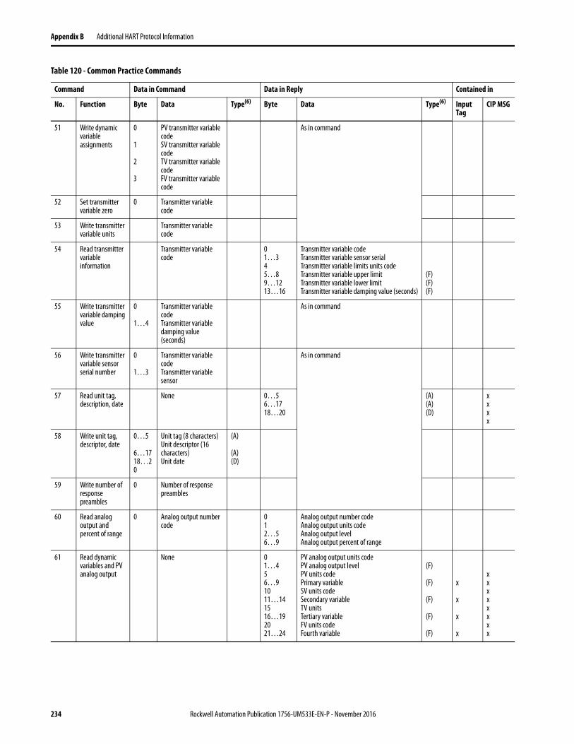
Appendix B Additional HART Protocol Information
51 Write dynamic variable assignments
0
1
2
3
PV transmitter variable codeSV transmitter variable codeTV transmitter variable codeFV transmitter variable code
As in command
52 Set transmitter variable zero
0 Transmitter variable code
53 Write transmitter variable units
Transmitter variable code
54 Read transmitter variable information
Transmitter variable code
01…345…89…1213…16
Transmitter variable codeTransmitter variable sensor serial Transmitter variable limits units codeTransmitter variable upper limitTransmitter variable lower limitTransmitter variable damping value (seconds)
(F)(F)(F)
55 Write transmitter variable damping value
0
1…4
Transmitter variable codeTransmitter variable damping value (seconds)
As in command
56 Write transmitter variable sensor serial number
0
1…3
Transmitter variable codeTransmitter variable sensor
As in command
57 Read unit tag, description, date
None 0…56…1718…20
(A)(A)(D)
xxxx
58 Write unit tag, descriptor, date
0…5
6…1718…20
Unit tag (8 characters)Unit descriptor (16 characters)Unit date
(A)
(A)(D)
59 Write number of response preambles
0 Number of response preambles
60 Read analog output and percent of range
0 Analog output number code
012…56…9
Analog output number codeAnalog output units codeAnalog output levelAnalog output percent of range
61 Read dynamic variables and PV analog output
None 01…456…91011…141516…192021…24
PV analog output units codePV analog output levelPV units codePrimary variableSV units codeSecondary variableTV unitsTertiary variableFV units codeFourth variable
(F)
(F)
(F)
(F)
(F)
x
x
x
x
xxxxxxxx
Table 120 - Common Practice Commands
Command Data in Command Data in Reply Contained in
No. Function Byte Data Type(6) Byte Data Type(6) Input Tag
CIP MSG
234 Rockwell Automation Publication 1756-UM533E-EN-P - November 2016
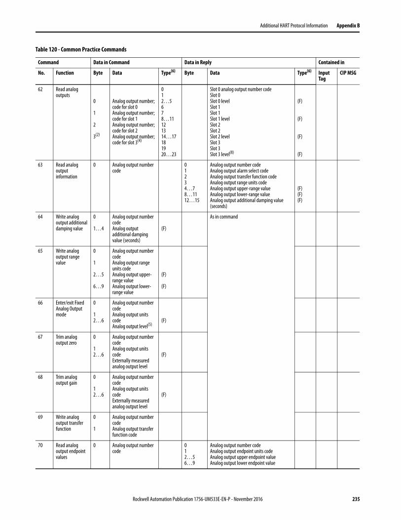
Additional HART Protocol Information Appendix B
62 Read analog outputs
0
1
2
3(2)
Analog output number;code for slot 0Analog output number;code for slot 1Analog output number;code for slot 2Analog output number;code for slot 3(4)
012…5678…11121314…17181920…23
Slot 0 analog output number code Slot 0 Slot 0 levelSlot 1 Slot 1 Slot 1 levelSlot 2 Slot 2 Slot 2 levelSlot 3 Slot 3 Slot 3 level(8)
(F)
(F)
(F)
(F)
63 Read analog output information
0 Analog output number code
01234…78…1112…15
Analog output number codeAnalog output alarm select codeAnalog output transfer function codeAnalog output range units codeAnalog output upper-range valueAnalog output lower-range valueAnalog output additional damping value (seconds)
(F)(F)(F)
64 Write analog output additional damping value
0
1…4
Analog output number codeAnalog output additional damping value (seconds)
(F)
As in command
65 Write analog output range value
0
1
2…5
6…9
Analog output number codeAnalog output range units codeAnalog output upper-range valueAnalog output lower-range value
(F)
(F)
66 Enter/exit Fixed Analog Output mode
0
12…6
Analog output number codeAnalog output units codeAnalog output level(5)
(F)
67 Trim analog output zero
0
12…6
Analog output number codeAnalog output units codeExternally measured analog output level
(F)
68 Trim analog output gain
0
12…6
Analog output number codeAnalog output units codeExternally measured analog output level
(F)
69 Write analog output transfer function
0
1
Analog output number codeAnalog output transfer function code
70 Read analog output endpoint values
0 Analog output number code
012…56…9
Analog output number codeAnalog output endpoint units codeAnalog output upper endpoint valueAnalog output lower endpoint value
Table 120 - Common Practice Commands
Command Data in Command Data in Reply Contained in
No. Function Byte Data Type(6) Byte Data Type(6) Input Tag
CIP MSG
Rockwell Automation Publication 1756-UM533E-EN-P - November 2016 235
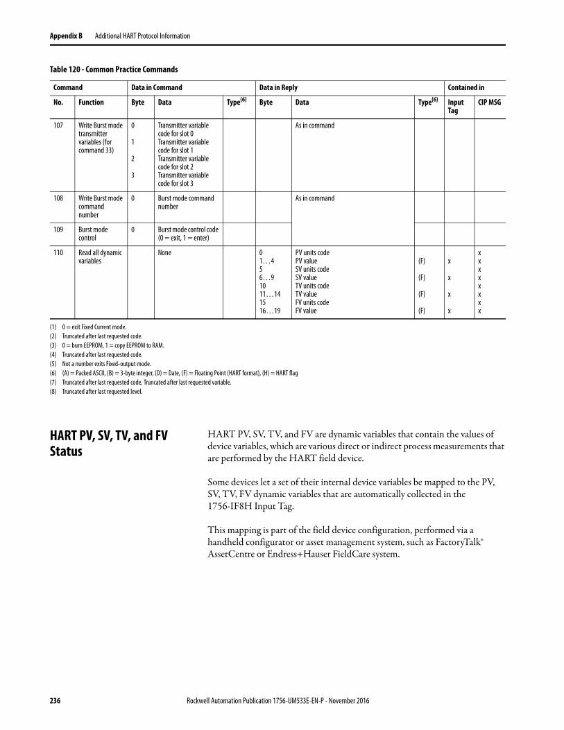
Appendix B Additional HART Protocol Information
HART PV, SV, TV, and FV Status
HART PV, SV, TV, and FV are dynamic variables that contain the values of device variables, which are various direct or indirect process measurements that are performed by the HART field device.
Some devices let a set of their internal device variables be mapped to the PV, SV, TV, FV dynamic variables that are automatically collected in the 1756-IF8H Input Tag.
This mapping is part of the field device configuration, performed via a handheld configurator or asset management system, such as FactoryTalk® AssetCentre or Endress+Hauser FieldCare system.
107 Write Burst mode transmitter variables (for command 33)
0
1
2
3
Transmitter variable code for slot 0Transmitter variable code for slot 1Transmitter variable code for slot 2Transmitter variablecode for slot 3
As in command
108 Write Burst mode command number
0 Burst mode command number
As in command
109 Burst mode control
0 Burst mode control code (0 = exit, 1 = enter)
110 Read all dynamic variables
None 01…456…91011…141516…19
PV units codePV valueSV units codeSV valueTV units codeTV valueFV units codeFV value
(F)
(F)
(F)
(F)
x
x
x
x
xxxxxxxx
(1) 0 = exit Fixed Current mode.(2) Truncated after last requested code.(3) 0 = burn EEPROM, 1 = copy EEPROM to RAM.(4) Truncated after last requested code.(5) Not a number exits Fixed-output mode.(6) (A) = Packed ASCII, (B) = 3-byte integer, (D) = Date, (F) = Floating Point (HART format), (H) = HART flag(7) Truncated after last requested code. Truncated after last requested variable.(8) Truncated after last requested level.
Table 120 - Common Practice Commands
Command Data in Command Data in Reply Contained in
No. Function Byte Data Type(6) Byte Data Type(6) Input Tag
CIP MSG
236 Rockwell Automation Publication 1756-UM533E-EN-P - November 2016
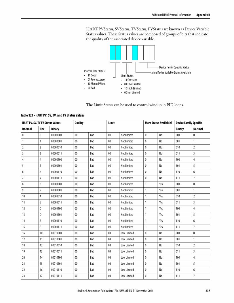
Additional HART Protocol Information Appendix B
HART PVStatus, SVStatus, TVStatus, FVStatus are known as Device Variable Status values. These Status values are composed of groups of bits that indicate the quality of the associated device variable.
The Limit Status can be used to control windup in PID loops.
Device Family Specific Status
More Device Variable Status AvailableLimit Status• 11 Constant• 01 Low Limited• 10 High Limited• 00 Not Limited
Process Data Status• 11 Good• 01 Poor Accuracy• 10 Manual/Fixed• 00 Bad
Table 121 - HART PV, SV, TV, and FV Status Values
HART PV, SV, TV FV Status Values Quality Limit More Status Available? Device Family Specific
Decimal Hex Binary Binary Decimal
0 0 00000000 00 Bad 00 Not Limited 0 No 000 0
1 1 00000001 00 Bad 00 Not Limited 0 No 001 1
2 2 00000010 00 Bad 00 Not Limited 0 No 010 2
3 3 00000011 00 Bad 00 Not Limited 0 No 011 3
4 4 00000100 00 Bad 00 Not Limited 0 No 100 4
5 5 00000101 00 Bad 00 Not Limited 0 No 101 5
6 6 00000110 00 Bad 00 Not Limited 0 No 110 6
7 7 00000111 00 Bad 00 Not Limited 0 No 111 7
8 8 00001000 00 Bad 00 Not Limited 1 Yes 000 0
9 9 00001001 00 Bad 00 Not Limited 1 Yes 001 1
10 A 00001010 00 Bad 00 Not Limited 1 Yes 010 2
11 B 00001011 00 Bad 00 Not Limited 1 Yes 011 3
12 C 00001100 00 Bad 00 Not Limited 1 Yes 100 4
13 D 00001101 00 Bad 00 Not Limited 1 Yes 101 5
14 E 00001110 00 Bad 00 Not Limited 1 Yes 110 6
15 F 00001111 00 Bad 00 Not Limited 1 Yes 111 7
16 10 00010000 00 Bad 01 Low Limited 0 No 000 0
17 11 00010001 00 Bad 01 Low Limited 0 No 001 1
18 12 00010010 00 Bad 01 Low Limited 0 No 010 2
19 13 00010011 00 Bad 01 Low Limited 0 No 011 3
20 14 00010100 00 Bad 01 Low Limited 0 No 100 4
21 15 00010101 00 Bad 01 Low Limited 0 No 101 5
22 16 00010110 00 Bad 01 Low Limited 0 No 110 6
23 17 00010111 00 Bad 01 Low Limited 0 No 111 7
Rockwell Automation Publication 1756-UM533E-EN-P - November 2016 237
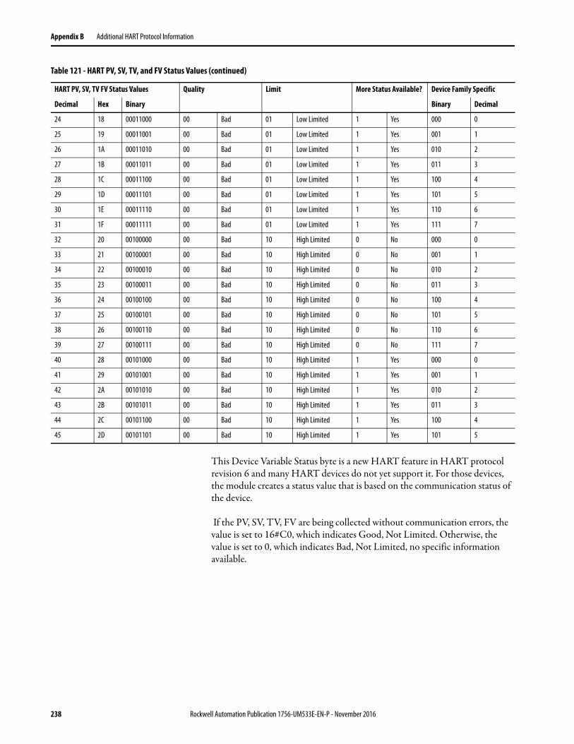
Appendix B Additional HART Protocol Information
This Device Variable Status byte is a new HART feature in HART protocol revision 6 and many HART devices do not yet support it. For those devices, the module creates a status value that is based on the communication status of the device.
If the PV, SV, TV, FV are being collected without communication errors, the value is set to 16#C0, which indicates Good, Not Limited. Otherwise, the value is set to 0, which indicates Bad, Not Limited, no specific information available.
24 18 00011000 00 Bad 01 Low Limited 1 Yes 000 0
25 19 00011001 00 Bad 01 Low Limited 1 Yes 001 1
26 1A 00011010 00 Bad 01 Low Limited 1 Yes 010 2
27 1B 00011011 00 Bad 01 Low Limited 1 Yes 011 3
28 1C 00011100 00 Bad 01 Low Limited 1 Yes 100 4
29 1D 00011101 00 Bad 01 Low Limited 1 Yes 101 5
30 1E 00011110 00 Bad 01 Low Limited 1 Yes 110 6
31 1F 00011111 00 Bad 01 Low Limited 1 Yes 111 7
32 20 00100000 00 Bad 10 High Limited 0 No 000 0
33 21 00100001 00 Bad 10 High Limited 0 No 001 1
34 22 00100010 00 Bad 10 High Limited 0 No 010 2
35 23 00100011 00 Bad 10 High Limited 0 No 011 3
36 24 00100100 00 Bad 10 High Limited 0 No 100 4
37 25 00100101 00 Bad 10 High Limited 0 No 101 5
38 26 00100110 00 Bad 10 High Limited 0 No 110 6
39 27 00100111 00 Bad 10 High Limited 0 No 111 7
40 28 00101000 00 Bad 10 High Limited 1 Yes 000 0
41 29 00101001 00 Bad 10 High Limited 1 Yes 001 1
42 2A 00101010 00 Bad 10 High Limited 1 Yes 010 2
43 2B 00101011 00 Bad 10 High Limited 1 Yes 011 3
44 2C 00101100 00 Bad 10 High Limited 1 Yes 100 4
45 2D 00101101 00 Bad 10 High Limited 1 Yes 101 5
Table 121 - HART PV, SV, TV, and FV Status Values (continued)
HART PV, SV, TV FV Status Values Quality Limit More Status Available? Device Family Specific
Decimal Hex Binary Binary Decimal
238 Rockwell Automation Publication 1756-UM533E-EN-P - November 2016
Appendix C
Manufacturer Identification Codes
This appendix identifies the manufacturer with their assigned code.
Decimal Hex Company Name
1 01 Acromag
2 02 Allen-Bradley
3 03 Ametek
4 04 Analog Devices
5 05 ABB
6 06 Beckman
7 07 Bell Microsenser
8 08 Bourns
9 09 Bristol Babcock
10 0A Brooks Instrument
11 0B Chessell
12 0C Combustion Engineering
13 0D Daniel Industries
14 0E Delta
15 0F Dieterich Standard
16 10 Dohrmann
17 11 Endress+Hauser
18 12 ABB
19 13 Fisher Controls
20 14 Foxboro
21 15 Fuji
22 16 ABB
23 17 Honeywell
24 18 ITT Barton
25 19 Thermo MeasureTech
26 1A ABB
27 1B Leeds & Northup
28 1C Leslie
29 1D M-System Co.
30 1E Measurex
31 1F Micro Motion
32 20 Moore Industries
Rockwell Automation Publication 1756-UM533E-EN-P - November 2016 239
Appendix C Manufacturer Identification Codes
33 21 PRIME Measurement Products
34 22 Ohkura Electric
35 23 Paine
36 24 Rochester Instrument Systems
37 25 Ronan
38 26 Rosemount
39 27 Peek Measurement
40 28 Actaris Neptune
41 29 Sensall
42 2A Siemens
43 2B Weed
44 2C Toshiba
45 2D Transmation
46 2E Rosemount Analytic
47 2F Metso Automation
48 30 Flowserve
49 31 Varec
50 32 Viatran
51 33 Delta/Weed
52 34 Westinghouse
53 35 Xomox
54 36 Yamatake
55 37 Yokogawa
56 38 Nuovo Pignone
57 39 Promac
58 3A Exac Corporation
59 3B Mobrey
60 3C Arcom Control System
61 3D Princo
62 3E Smar
63 3F Foxboro Eckardt
64 40 Measurement Technology
65 41 Applied System Technologies
66 42 Samson
67 43 Sparling Instruments
68 44 Fireye
69 45 Krohne
70 46 Betz
71 47 Druck
72 48 SOR
Decimal Hex Company Name
240 Rockwell Automation Publication 1756-UM533E-EN-P - November 2016
Manufacturer Identification Codes Appendix C
73 49 Elcon Instruments
74 4A EMCO
75 4B Termiflex Corporation
76 4C VAF Instruments
77 4D Westlock Controls
78 4E Drexelbrook
79 4F Saab Tank Control
80 50 K-TEK
81 51 SENSIDYNE, INC
82 52 Draeger
83 53 Raytek
84 54 Siemens Milltronics PI
85 55 BTG
86 56 Magnetrol
87 58 Metso Automation
88 59 Siemens Milltronics PI
89 59 HELIOS
90 5A Anderson Instrument Company
91 5B INOR
92 5C ROBERTSHAW
93 5D PEPPERL+FUCHS
94 5E ACCUTECH
95 5F Flow Measurement
96 60 Courdon-Haenni
97 61 Knick
98 62 VEGA
99 63 MTS Systems Corp.
100 64 Oval
101 65 Masoneilan-Dresser
102 66 BESTA
103 67 Ohmart
104 68 Harold Beck and Sons
105 69 rittmeyer instrumentation
106 6A Rossel Messtechnik
107 6B WIKA
108 6C Bopp & Reuther Heinrichs
109 6D PR Electronics
110 6E Jordan Controls
111 6F Valcom s.r.l.
112 70 US ELECTRIC MOTORS
Decimal Hex Company Name
Rockwell Automation Publication 1756-UM533E-EN-P - November 2016 241
Appendix C Manufacturer Identification Codes
113 71 Apparatebau Hundsbach
114 72 Dynisco
115 73 Spriano
116 74 Direct Measurement
117 75 Klay Instruments
118 76 CiDRA CORP.
119 77 MMG AM DTR
120 78 Buerkert Fluid Control Systems
121 79 AALIANT Process Mgt
122 7A PONDUS INSTRUMENTS
123 7B ZAP S.A. Ostrow Wielkopolski
124 7C GLI
125 7D Fisher-Rosemount Performance Technologies
126 7E Paper Machine Components
127 7F LABOM
128 80 Danfoss
129 81 Turbo
130 82 TOKYO KEISO
131 83 SMC
132 84 Status Instruments
133 85 Huakong
134 86 Duon System
135 87 Vortek Instruments, LLC
136 88 AG Crosby
137 89 Action Instruments
138 8A Keystone Controls
139 8B Thermo Electronic Co.
140 8C ISE Magtech
141 8D Rueger
142 8E Mettler Toledo
143 8F Det-Tronics
144 90 Thermo MeasureTech
145 91 DeZURIK
146 92 Phase Dynamics
147 93 WELLTECH SHANGHAI
148 94 ENRAF
149 95 4tech ASA
150 96 Brandt Instruments
151 97 Nivelco
152 98 Camille Bauer
Decimal Hex Company Name
242 Rockwell Automation Publication 1756-UM533E-EN-P - November 2016
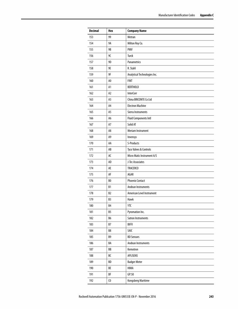
Manufacturer Identification Codes Appendix C
153 99 Metran
154 9A Milton Roy Co.
155 9B PMV
156 9C Turck
157 9D Panametrics
158 9E R. Stahl
159 9F Analytical Technologies Inc.
160 A0 FINT
161 A1 BERTHOLD
162 A2 InterCorr
163 A3 China BRICONTE Co Ltd
164 A4 Electron Machine
165 A5 Sierra Instruments
166 A6 Fluid Components Intl
167 A7 Solid AT
168 A8 Meriam Instrument
169 A9 Invensys
170 AA S-Products
171 AB Tyco Valves & Controls
172 AC Micro Matic Instrument A/S
173 AD J-Tec Associates
174 AE TRACERCO
175 AF AGAR
176 B0 Phoenix Contact
177 B1 Andean Instruments
178 B2 American Level Instrument
179 B3 Hawk
180 B4 YTC
181 B5 Pyromation Inc.
182 B6 Satron Instruments
183 B7 BIFFI
184 B8 SAIC
185 B9 BD Sensors
186 BA Andean Instruments
187 BB Kemotron
188 BC APLISENS
189 BD Badger Meter
190 BE HIMA
191 BF GP:50
192 C0 Kongsberg Maritime
Decimal Hex Company Name
Rockwell Automation Publication 1756-UM533E-EN-P - November 2016 243
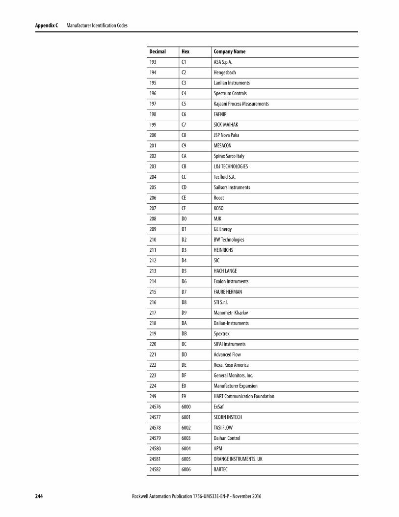
Appendix C Manufacturer Identification Codes
193 C1 ASA S.p.A.
194 C2 Hengesbach
195 C3 Lanlian Instruments
196 C4 Spectrum Controls
197 C5 Kajaani Process Measurements
198 C6 FAFNIR
199 C7 SICK-MAIHAK
200 C8 JSP Nova Paka
201 C9 MESACON
202 CA Spirax Sarco Italy
203 CB L&J TECHNOLOGIES
204 CC Tecfluid S.A.
205 CD Sailsors Instruments
206 CE Roost
207 CF KOSO
208 D0 MJK
209 D1 GE Energy
210 D2 BW Technologies
211 D3 HEINRICHS
212 D4 SIC
213 D5 HACH LANGE
214 D6 Exalon Instruments
215 D7 FAURE HERMAN
216 D8 STI S.r.l.
217 D9 Manometr-Kharkiv
218 DA Dalian-Instruments
219 DB Spextrex
220 DC SIPAI Instruments
221 DD Advanced Flow
222 DE Rexa. Koso America
223 DF General Monitors, Inc.
224 E0 Manufacturer Expansion
249 F9 HART Communication Foundation
24576 6000 ExSaf
24577 6001 SEOJIN INSTECH
24578 6002 TASI FLOW
24579 6003 Daihan Control
24580 6004 APM
24581 6005 ORANGE INSTRUMENTS. UK
24582 6006 BARTEC
Decimal Hex Company Name
244 Rockwell Automation Publication 1756-UM533E-EN-P - November 2016
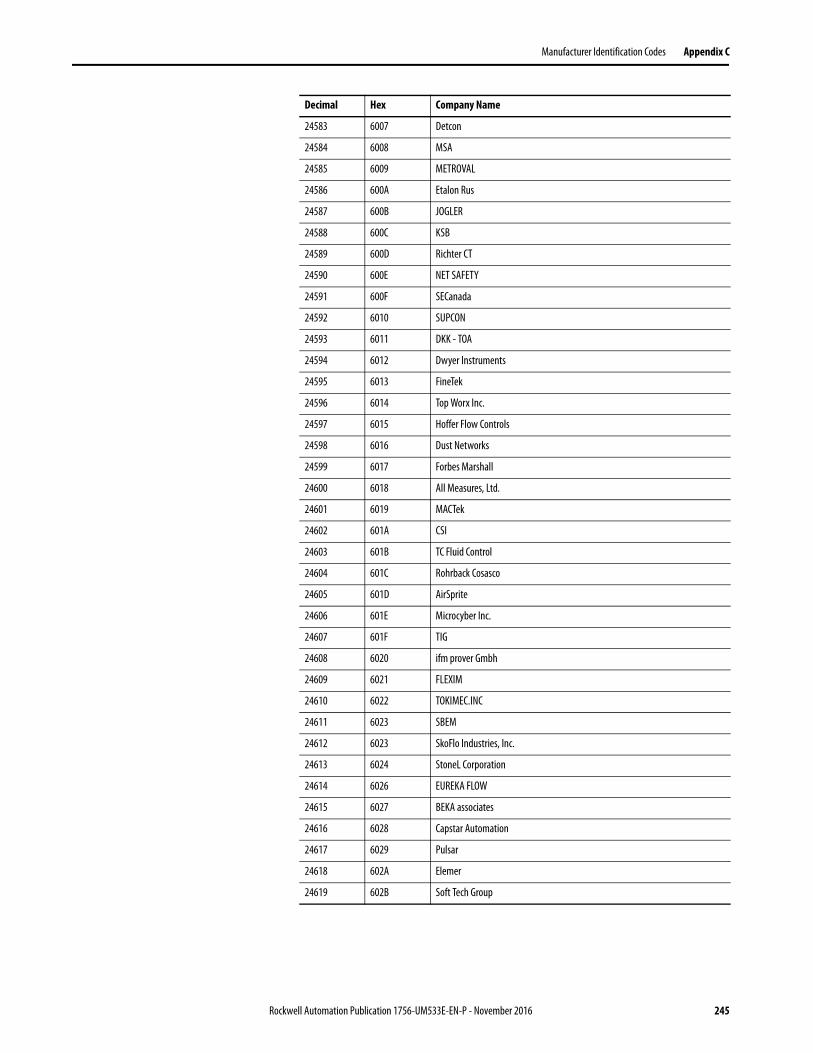
Manufacturer Identification Codes Appendix C
24583 6007 Detcon
24584 6008 MSA
24585 6009 METROVAL
24586 600A Etalon Rus
24587 600B JOGLER
24588 600C KSB
24589 600D Richter CT
24590 600E NET SAFETY
24591 600F SECanada
24592 6010 SUPCON
24593 6011 DKK - TOA
24594 6012 Dwyer Instruments
24595 6013 FineTek
24596 6014 Top Worx Inc.
24597 6015 Hoffer Flow Controls
24598 6016 Dust Networks
24599 6017 Forbes Marshall
24600 6018 All Measures, Ltd.
24601 6019 MACTek
24602 601A CSI
24603 601B TC Fluid Control
24604 601C Rohrback Cosasco
24605 601D AirSprite
24606 601E Microcyber Inc.
24607 601F TIG
24608 6020 ifm prover Gmbh
24609 6021 FLEXIM
24610 6022 TOKIMEC.INC
24611 6023 SBEM
24612 6023 SkoFlo Industries, Inc.
24613 6024 StoneL Corporation
24614 6026 EUREKA FLOW
24615 6027 BEKA associates
24616 6028 Capstar Automation
24617 6029 Pulsar
24618 602A Elemer
24619 602B Soft Tech Group
Decimal Hex Company Name
Rockwell Automation Publication 1756-UM533E-EN-P - November 2016 245

Appendix C Manufacturer Identification Codes
Notes:
246 Rockwell Automation Publication 1756-UM533E-EN-P - November 2016
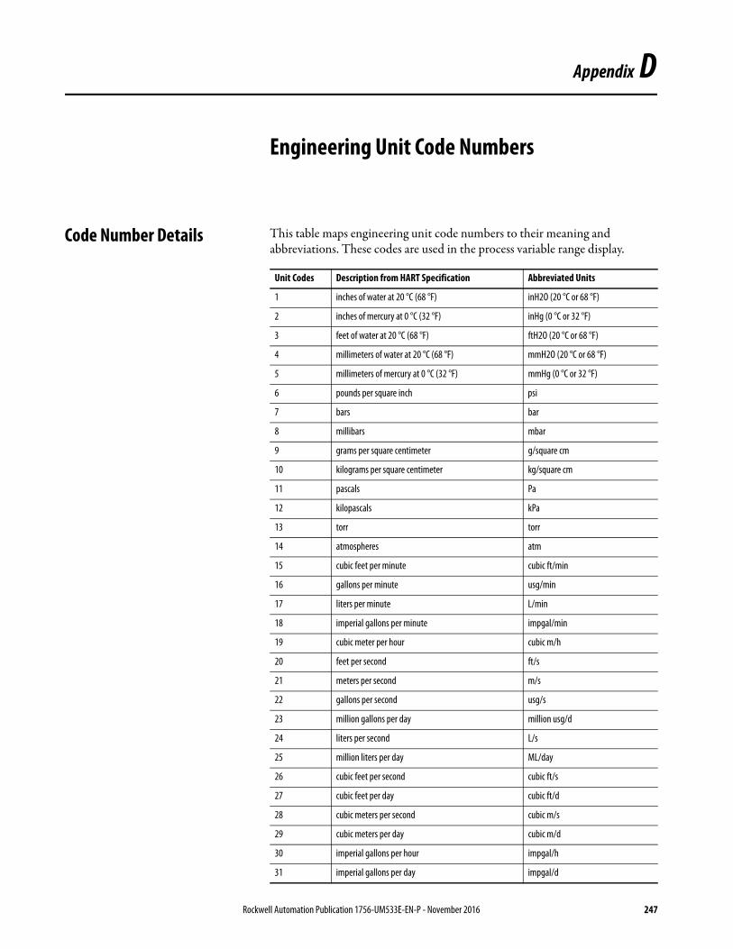
Appendix D
Engineering Unit Code Numbers
Code Number Details This table maps engineering unit code numbers to their meaning and abbreviations. These codes are used in the process variable range display.
Unit Codes Description from HART Specification Abbreviated Units
1 inches of water at 20 °C (68 °F) inH2O (20 °C or 68 °F)
2 inches of mercury at 0 °C (32 °F) inHg (0 °C or 32 °F)
3 feet of water at 20 °C (68 °F) ftH2O (20 °C or 68 °F)
4 millimeters of water at 20 °C (68 °F) mmH2O (20 °C or 68 °F)
5 millimeters of mercury at 0 °C (32 °F) mmHg (0 °C or 32 °F)
6 pounds per square inch psi
7 bars bar
8 millibars mbar
9 grams per square centimeter g/square cm
10 kilograms per square centimeter kg/square cm
11 pascals Pa
12 kilopascals kPa
13 torr torr
14 atmospheres atm
15 cubic feet per minute cubic ft/min
16 gallons per minute usg/min
17 liters per minute L/min
18 imperial gallons per minute impgal/min
19 cubic meter per hour cubic m/h
20 feet per second ft/s
21 meters per second m/s
22 gallons per second usg/s
23 million gallons per day million usg/d
24 liters per second L/s
25 million liters per day ML/day
26 cubic feet per second cubic ft/s
27 cubic feet per day cubic ft/d
28 cubic meters per second cubic m/s
29 cubic meters per day cubic m/d
30 imperial gallons per hour impgal/h
31 imperial gallons per day impgal/d
Rockwell Automation Publication 1756-UM533E-EN-P - November 2016 247

Appendix D Engineering Unit Code Numbers
32 Degrees Celsius °C
33 Degrees Fahrenheit °F
34 Degrees Rankine °R
35 Kelvin °K
36 millivolts mV
37 ohms ohm
38 hertz hz
39 milliamperes mA
40 gallons usg
41 liters L
42 imperial gallons impgal
43 cubic meters cubic m
44 feet ft
45 meters m
46 barrels bbl
47 inches in
48 centimeters cm
49 millimeters mm
50 minutes min
51 seconds s
52 hours h
53 days d
54 centistokes centistokes
55 centipoise cP
56 microsiemens microsiemens
57 percent %
58 volts V
59 pH pH
60 grams g
61 kilograms kg
62 metric tons t
63 pounds lb
64 short tons short ton
65 long tons long ton
66 milli siemens per centimeter millisiemens/cm
67 micro siemens per centimeter microsiemens/cm
68 newton N
69 newton meter N m
70 grams per second g/s
71 grams per minute g/min
Unit Codes Description from HART Specification Abbreviated Units
248 Rockwell Automation Publication 1756-UM533E-EN-P - November 2016
Engineering Unit Code Numbers Appendix D
72 grams per hour g/h
73 kilograms per second kg/s
74 kilograms per minute kg/min
75 kilograms per hour kg/h
76 kilograms per day kg/d
77 metric tons per minute t/min
78 metric tons per hour t/h
79 metric tons per day t/d
80 pounds per second lb/s
81 pounds per minute lb/min
82 pounds per hour lb/h
83 pounds per day lb/d
84 short tons per minute short ton/min
85 short tons per hour short ton/h
86 short tons per day short ton/d
87 long tons per hour long ton/h
88 long tons per day long ton/d
89 deka therm Dth
90 specific gravity units specific gravity units
91 grams per cubic centimeter g/cubic cm
92 kilograms per cubic meter kg/cubic m
93 pounds per gallon lb/usg
94 pounds per cubic feet lb/cubic ft
95 grams per milliliter g/mL
96 kilograms per liter kg/L
97 grams per liter g/L
98 pounds per cubic inch lb/cubic in
99 short tons per cubic yard short ton/cubic yd
100 degrees twaddell °Tw
101 degrees brix °Bx
102 degrees baume heavy BH
103 degrees baume light BL
104 degrees API °API
105 percent solids per weight % solid/weight
106 percent solids per volume % solid/volume
107 degrees balling degrees balling
108 proof per volume proof/volume
109 proof per mass proof/mass
110 bushels bushel
111 cubic yards cubic yd
Unit Codes Description from HART Specification Abbreviated Units
Rockwell Automation Publication 1756-UM533E-EN-P - November 2016 249
Appendix D Engineering Unit Code Numbers
112 cubic feet cubic ft
113 cubic inches cubic in
114 inches per second in/s
115 inches per minute in/min
116 feet per minute ft/min
117 degrees per second °/s
118 revolutions per second rev/s
119 revolutions per minute rpm
120 meters per hour m/hr
121 normal cubic meter per hour normal cubic m/h
122 normal liter per hour normal L/h
123 standard cubic feet per minute standard cubic ft/min
124 bbl liq bbl liq
125 ounce oz
126 foot pound force ft lb force
127 kilo watt kW
128 kilo watt hour kW h
129 horsepower hp
130 cubic feet per hour cubic ft/h
131 cubic meters per minute cubic m/min
132 barrels per second bbl/s
133 barrels per minute bbl/min
134 barrels per hour bbl/h
135 barrels per day bbl/d
136 gallons per hour usg/h
137 imperial gallons per second impgal/s
138 liters per hour L/h
139 parts per million ppm
140 mega calorie per hour Mcal/h
141 mega joule per hour MJ/h
142 british thermal unit per hour BTU/h
143 degrees degrees
144 radian rad
145 inches of water at 15.6 °C (60 °F) inH2O (15.6 °C or 60 °F)
146 micrograms per liter micrograms/L
147 micrograms per cubic meter micrograms/cubic m
148 percent consistency % consistency
149 volume percent volume %
150 percent steam quality % steam quality
151 feet in sixteenths ft in sixteenths
Unit Codes Description from HART Specification Abbreviated Units
250 Rockwell Automation Publication 1756-UM533E-EN-P - November 2016
Engineering Unit Code Numbers Appendix D
152 cubic feet per pound cubic ft/lb
153 picofarads pF
154 mililiters per liter mL/L
155 microliters per liter microliters/L
156 percent plato % plato
157 percent lower explosion level % lower explosion level
158 mega calorie Mcal
159 Kohms kohm
160 mega joule MJ
161 british thermal unit BTU
162 normal cubic meter normal cubic m
163 normal liter normal L
164 standard cubic feet normal cubic ft
165 parts per billion parts/billion
235 gallons per day usg/d
236 hectoliters hL
237 megapascals MPa
238 inches of water at 4 °C (39.2 °F) inH2O (4 °C or 39.2 °F)
239 millimeters of water at 4 °C (39.2 °F) mmH2O (4 °C or 39.2 °F)
Unit Codes Description from HART Specification Abbreviated Units
Rockwell Automation Publication 1756-UM533E-EN-P - November 2016 251

Appendix D Engineering Unit Code Numbers
Notes:
252 Rockwell Automation Publication 1756-UM533E-EN-P - November 2016
Glossary
The following terms and abbreviations are used throughout this manual. For definitions of terms that are not listed here, refer to the Allen-Bradley Industrial Automation Glossary, publication AG-7.1.
balanced circuit 1) A circuit whose two sides are electrically alike and symmetrical to a common reference point, usually ground. 2) Contrasted with unbalanced circuit (page 255).
broadcast Data transmissions to all addresses.
CIP Acronym for Common Industrial Protocol; a communication protocol, or language, between industrial devices. CIP provides seamless communication for devices on DeviceNet, ControlNet, and EtherNet/IP networks.
compatible match An Electronic Keying Protection mode that requires the physical module and the module that is configured in the software to match according to vendor, catalog number, and major revision. The minor revision of the module must be greater than or equal to that configured.
connection The continuous communication mechanism from the controller to an I/O module in the control system.
ControlBus The backplane that is used by the 1756 chassis.
coordinated system time (CST) Timer value, which is kept synchronized for all modules within one ControlBus™ chassis. The CST is a 64-bit number with microsecond resolution.
differential 1) Pertaining to a method of signal transmission through two wires. The transmission always has opposite states. The signal data is the polarity difference between the wires; when one is high, the other is low. Neither wire is grounded. The circuit can be either a balanced circuit, a floating circuit, or a circuit with a high-impedance path to ground from either end. Used regarding encoders, analog I/O circuits, and communication circuits. 2) Contrasted with single-ended (page 255).
direct connection An I/O connection, where the controller establishes an individual connection with I/O modules.
disable keying An option that turns off all electronic keying to the module. Requires no attributes of the physical module and the module that is configured in the software to match. A connection is attempted to the module even if it is the wrong type.
download The process of transferring the contents of a project on the workstation into the controller.
electronic keying A system feature that makes sure that physical module attributes are consistent with what was configured in software.
Rockwell Automation Publication 1756-UM533E-EN-P - November 2016 253
Glossary
exact match An Electronic Keying Protection mode that requires the physical module and the module that is configured in the software to match identically, according to vendor, catalog number, major revision, and minor revision.
field side Interface between user field wiring and I/O module. In this glossary, see related entry for system side.
flash update The process of updating the firmware of the module.
fourth value (FV) Also abbreviated as QV for quaternary value, this dynamic variable contains the fourth value of Device Variables, which are direct or indirect process measurements by a HART field device.
frequency shift keying A method of using frequency modulation to send digital information that is used by HART field devices.
Hard Run mode Mode where keyswitch of controller is in Run position.
HART Acronym for highway addressable remote transducer.
inhibit A ControlLogix® process that lets you configure an I/O module, but prevent it from communicating with the owner-controller. In this case, the controller does not establish a connection.
Input Data format Format that defines the type of information that is transferred between an I/O module and its owner-controller. This format also defines the tags that are created for each I/O module.
interface module (IFM) A pre-wired removable terminal block (RTB).
listen-only connection An I/O connection that lets a controller monitor I/O module data without owning the module, sending it a configuration, or controlling its outputs.
major revision A module revision that is updated any time there is a functional change to the module, and results in an interface change with software.
minor revision A module revision that is updated any time there is a change to the module that does not affect its function or software user interface.
multicast Data transmissions that reach a specific group of one or more destinations.
multiple owners A configuration setup where multiple owner-controllers use the same configuration information to simultaneously own an input module.
network update time (NUT) The smallest repetitive time interval in which the data can be sent on a ControlNet network. The NUT can be configured over the range from2…100 ms using RSNetWorx™ software.
owner-controller The controller that creates and stores the primary configuration and communication connection to a module.
254 Rockwell Automation Publication 1756-UM533E-EN-P - November 2016
Glossary
primary value (PV) Dynamic variable that contains the primary value of Device Variables, which are direct or indirect process measurements by a HART field device. See page 16 for more information.
Program mode In this mode, the controller program is not executing. Inputs are actively producing data. Outputs are not actively controlled and go to their configured Program mode state.
remote connection An I/O connection where the controller establishes an individual connection with I/O modules in a remote chassis.
removable terminal block (RTB) Field wiring connector for I/O modules.
removal and insertion under power(RIUP)
ControlLogix feature that lets you install or remove a module or RTB while power is applied.
requested packet interval (RPI) A configurable parameter that defines when the module will multicast data.
Run mode In this mode, the controller program is executing. Inputs are actively producing data. Outputs are actively controlled.
secondary value (SV) Dynamic variable that contains the secondary value of Device Variables, which are direct or indirect process measurements by a HART field device.
service A system feature that is performed on user demand.
single-ended 1) Unbalanced, as when one side is grounded. See unbalanced circuit (page 255) 2) Contrasted with differential (page 253).
system side Backplane side of the interface to the I/O module. In this glossary, see related entry for field side.
tag A named area of the memory of the controller where data is stored like a variable.
third value (TV) Dynamic variable that contains the tertiary, or third, value of Device Variables, which are direct or indirect process measurements by a HART field device.
timestamping ControlLogix process that stamps a change in input, output, or diagnostic data with a time reference that indicates when that change occurred.
unbalanced circuit 1) A circuit whose two sides are electrically dissimilar, as when one side is grounded. 2) Contrasted with balanced circuit (page 253).
Rockwell Automation Publication 1756-UM533E-EN-P - November 2016 255

Glossary
Notes:
256 Rockwell Automation Publication 1756-UM533E-EN-P - November 2016
Index
Numerics1756-IF16H module
analog and HART by channel tags 89analog and HART PV tags 88analog only tags 87channel faults 85configuration tags 86data formats 75fault reporting 83, 99features 75input channel ranges 76input tags, analog and HART by channel 89input tags, analog and HART PV 88input tags, analog only 87wiring diagram 80
1756-IF16IH modulechannel faults 100configuration tags 102
Configure HART Device = No 102data formats 91, 93fault reporting 99features 91input channel ranges 93input tags, analog and HART by channel 105input tags, analog and HART PV 104input tags, analog only 103Set Device Info 168wiring diagram 97
1756-IF8H moduleanalog and HART by channel tags 51analog and HART PV tags 49analog only tags 48configuration tags 47data formats 33features 33input channel ranges 34input tags, analog and HART PV 49input tags, analog only 48wiring diagram 40
1756-IF8IH moduleanalog and HART by channel tags 72auto-configure HART device 59channel faults 63configuration tags
Configure HART Device = No 65Configure HART Device = Yes 66
data formats 53, 55fault reporting 62features 53, 91filter
digital 57HART compatibility 54input channel ranges 55input ranges 53input tags, analog and HART by channel
Configure HART Device = No 70Configure HART Device = Yes 72
input tags, analog and HART PV 68input tags, analog only 67isolation 53output tags, analog and HART by channel
Configure HART Device = Yes 74process alarms 60Set Device Info 168wiring diagram 61
1756-OF8H moduleanalog and HART by channel tags 121analog and HART PV tags 119analog only tags 118configuration tags 117data formats 107fault reporting 113features 107input tags
analog and HART PV 138input tags, analog only 118output tags 122wiring diagram 111
1756OF8H moduleinput tags, analog and HART PV 119
1756-OF8IH moduleauto-configure HART device 127channel faults 131configuration tags
Configure HART Device = No 134Configure HART Device = Yes 136
data formats 123fault mode output state 125fault reporting 129features 123input tags
analog only 137input tags, analog and HART by channel
Configure HART Device = No 139Configure HART Device = Yes 141
input tags, analog and HART PV 138input tags, analog only 137module faults 131output tags
Configure HART Device = No 143Configure HART Device = Yes 143
powerup state 125Set Device Info 168wiring diagram 128write HART variables 127
Aalarm
1756-IF8H tab 158clamp limit 110, 127deadband 38process 38rate 39, 59
alarm deadband 60all channels
configuration 156output configuration 161
asset managementHART modules 199software 19
assignmentdynamic variable 173
auto-configure HART device 59
Rockwell Automation Publication 1756-UM533E-EN-P - November 2016 257
Index
Ccalibration tab 170channel
configuration 152input status 46, 85, 101output status 116, 132
channel faults1756-IF16H module 851756-IF16IH module 1001756-IF8IH module 631756-OF8IH module 131
CIP messagingHART data 177pass-through HART data 187
circuitinput diagram
1756-IF16H module 82, 981756IF8H module 421756-IF8IH module 61
output diagram1756-OF8H module 1121756-OF8IH module 128
clamp limitalarm 110, 127output module 110, 126
command 3 or 9dynamic variable assignment 173
communicationfault 163HART 17unicast 32
componentsmodule 14
configurationall channels 156all output channels 161channel 152configuration tab for input modules 151HART devices 148input channels 160module 145output tab 160
connection 253direct connection 253direct connections 22listen-only 30tab 149
controllerHART 13
ControlNet network 26, 29 … 30coordinated system time (CST) 150, 253create a module 145
Ddata
collection 174echo
output modules 111, 127formats
1756-IF16H module 751756-IF16IH module 93
1756-IF8IH module 551756-OF8IH 124input module 34, 76output module 108
input tag 170tags
1756-I16IH module 1011756-IF8H module 46, 86, 1171756-IF8IH module 651756-OF8IH module 134
Data Echo 127data formats
1756-IF16IH module 911756-IF8H module 331756-IF8IH module 531756-OF8H module 1071756-OF8IH module 123
detectionopen circuit 58open wire 110, 126underrange and overrange 36, 58, 78, 96wire-off 80
digitalfilter 37flter 79
direct connection 22, 253dynamic variable assignment 173
Eelectronic keying 20, 253
compatible match 253disable keying 253exact match 254
engineering unitcode numbers 247scaling 153
EtherNet/IP network 27, 30event tasks 25
Ffault
codes 221communication 163reporting
1756-IF16IH module 991756-IF8H module 431756-IF8IH module 621756-OF8IH 129
fault mode output state1756-OF8IH 125
features1756-IF16H module 751756-IF16IH module 911756-IF8H module 331756-IF8IH module 53, 911756-OF8H module 1071756-OF8IH module 123
filterchannel ADC 56, 93digital 37, 79
258 Rockwell Automation Publication 1756-UM533E-EN-P - November 2016
Index
1756-IF8IH module 57input module 77module 35
fourth value definition 18
Ggeneral tab 147glossary of terms 253
HHART
additional protocol information 227communication 17data via MSG instructions 177definition 254device
auto-configuration 127configuration 148
device information tab 165getting data over CIP MSG 177integrated networks 18Logix controller 13protocol 17variables 171writing variables 127
HART command tab 169HART compatibility
1756-IF8IH module 54hold
initialization 109, 126
Iinhibit module 254initialization
hold 109, 126input
circuit diagram1756-IF16H module 821756-IF8H module, current 421756-IF8H module, voltage 431756-IF8IH module 61
error codes 222, 223module
channel ranges 34channel status 46, 85, 101data formats 34, 76filter 77local chassis 23multiple owners 31operation 22real time sample 36, 58, 96remote chassis 26
tag data 170input ranges
1756-IF16H module 761756-IF16IH module 931756-IF8IH module 53, 55
input tagsanalog and HART by channel
Configure HART Device = No 105
isolation1756-IF8IH module 53
Kkeying
electronic 20RTB 16
Lladder logic
message configuration 206message instructions 203unlatch alarms (1756-IF6I module) 210unlatch alarms (1756-OF6VI module) 212
limits tab 164listen-only connection 30local chassis
input module 23output module 28
Mmajor revision 254manufacturer ID codes 239minor revision 254module
accessories 15components 14configuration 145creation 145data collection 174filter 35
channel ADC filter 56, 93keying 20operation 21refresh 150removal 224resolution 157scaling 19status 150tab 149troubleshooting 215
module faults1756-OF8IH module 131
Nnetwork update time (NUT)
for ControlNet network 254
Oopen circuit detection 58open wire detection 110, 126operation
input module 22module 21output 28
Rockwell Automation Publication 1756-UM533E-EN-P - November 2016 259
Index
output1756-OF8IH
data formats 124circuit diagram
1756-OF8H module 1121756-OF8IH module 128
data echo 28error codes 223module
channel status 116, 132circuit diagrams 112clamp limit 110, 126data formats 108local chassis 28ramp rate 162ramp/rate 109, 125remote chassis 29resolution 108wiring 111
operation 28state
module tab 162overrange
detection 36, 58, 78, 96ownership
changing configuration in multiple owner-controllers 32
multiple owners 31, 32, 254owner-controller 254
Ppass-through messages 177, 187, 189, 191,
194, 216, 217power supply
input wiring 41wiring 81
powerup state1756-OF8IH module 125
primary value definition 18process alarms 60protocol
HART 17
Rramp rate limit
output module 109, 125, 162rate alarm 59real time sample (RTS) 23, 36, 58, 78, 96
in a local chassis 23in a remote chassis 26
refresh module 150remote chassis
connecting via ControlNet network 26, 29 … 30
connecting via EtherNet/IP network 27, 30input module 26output module 29
removeand insert under power (RIUP) 255module 224
requested packet interval (RPI) 24, 255local chassis 23
resolutionmodule 157output module 108
revisionmajor 254minor 254
RPI 23, 24RTB keying 16RTS. See real time sample
Sscaling
engineering units 153module 19
secondary value definition 18Set Device Info 168software
asset management 19status
module 150
Ttab
1756-IF8H alarm 158connection 149general 147HART device information 165input configuration 151module 149output configuration 160output limits 164output state 162
tasksevent 25
third value definition 18timestamp 19triggering event tasks 25troubleshooting
module 215
Uunderrange
detection 36, 58, 78, 96unicast
communication 32connection 149
unlatch alarms 209
Vvariables
HART 171
260 Rockwell Automation Publication 1756-UM533E-EN-P - November 2016
Index
Wwire-off detection 80wiring
analog interface modules (AIFM) 225input diagrams 40, 80, 97output module 111power supply 41, 81pre-wired cables 225
wiring diagram1756-IF16H module 801756-IF16IH module 971756-IF8H module 401756-IF8IH module 611756-OF8H module 1111756-OF8IH module 128
Rockwell Automation Publication 1756-UM533E-EN-P - November 2016 261

Index
Notes:
262 Rockwell Automation Publication 1756-UM533E-EN-P - November 2016

Publication 1756-UM533E-EN-P - November 2016Supersedes Publication 1756-UM533D-EN-P - January 2015 Copyright © 2016 Rockwell Automation, Inc. All rights reserved. Printed in the U.S.A.
Rockwell Automation SupportUse the following resources to access support information.
Documentation FeedbackYour comments will help us serve your documentation needs better. If you have any suggestions on how to improve this document, complete the How Are We Doing? form at http://literature.rockwellautomation.com/idc/groups/literature/documents/du/ra-du002_-en-e.pdf.
Technical Support Center Knowledgebase Articles, How-to Videos, FAQs, Chat, User Forums, and Product Notification Updates. https://rockwellautomation.custhelp.com/
Local Technical Support Phone Numbers Locate the phone number for your country. http://www.rockwellautomation.com/global/support/get-support-now.page
Direct Dial Codes Find the Direct Dial Code for your product. Use the code to route your call directly to a technical support engineer. http://www.rockwellautomation.com/global/support/direct-dial.page
Literature Library Installation Instructions, Manuals, Brochures, and Technical Data. http://www.rockwellautomation.com/global/literature-library/overview.page
Product Compatibility and Download Center (PCDC)
Get help determining how products interact, check features and capabilities, and find associated firmware. http://www.rockwellautomation.com/global/support/pcdc.page
.
Rockwell Otomasyon Ticaret A.Ş., Kar Plaza İş Merkezi E Blok Kat:6 34752 İçerenköy, İstanbul, Tel: +90 (216) 5698400
Rockwell Automation maintains current product environmental information on its website at http://www.rockwellautomation.com/rockwellautomation/about-us/sustainability-ethics/product-environmental-compliance.page.
Allen-Bradley, ControlBus, ControlFLASH, ControlLogix, FactoryTalk, Logix5000, Rockwell Automation, Rockwell Software, RSLinx, RSLogix 5000, RSNetWorx, Studio 5000, and Studio 5000 Logix Designer are trademarks of Rockwell Automation, Inc.