Embed Size (px)
Citation preview

Convection Heat Transfer
Reading Problems12-1→ 12-8 12-40, 12-49, 12-68, 12-70, 12-87, 12-9813-1→ 13-6 13-39, 13-47, 13-5914-1→ 14-4 14-18, 14-24, 14-45, 14-82
Introduction
↙ ↘Newton’s Law of Cooling
Qconv =∆T
Rconv
= hA(Tw − T∞)
⇒ Rconv =1
hA
Typical Values of h (W/m2K)
Natural gases: 3-20Convection water: 60 - 900
Forced gases: 30 - 300Convection oils: 60 - 1800
water: 100 -1500
Boiling water: 3000 - 105
Condensation steam: 3000 - 105
Controlling Factors
Geometry: shape, size, aspect ratio and orientationFlow Type: forced, natural, laminar, turbulent,
internal, externalBoundary: isothermal (Tw = constant) or
isoflux (qw = constant)Fluid Type: viscous oil, water, gases or liquid metalsProperties: all properties determined at film temperature
Tf = (Tw + T∞)/2Note: ρ and ν ∝ 1/Patm ⇒ see Q12-40density: ρ ((kg/m3)specific heat: Cp (J/kg ·K)
dynamic viscosity: µ, (N · s/m2)
kinematic viscosity: ν ≡ µ/ρ (m2/s)
thermal conductivity: k, (W/m ·K)
thermal diffusivity: α, ≡ k/(ρ · Cp) (m2/s)
Prandtl number: Pr, ≡ ν/α (−−)
volumetric compressibility: β, (1/K)
1
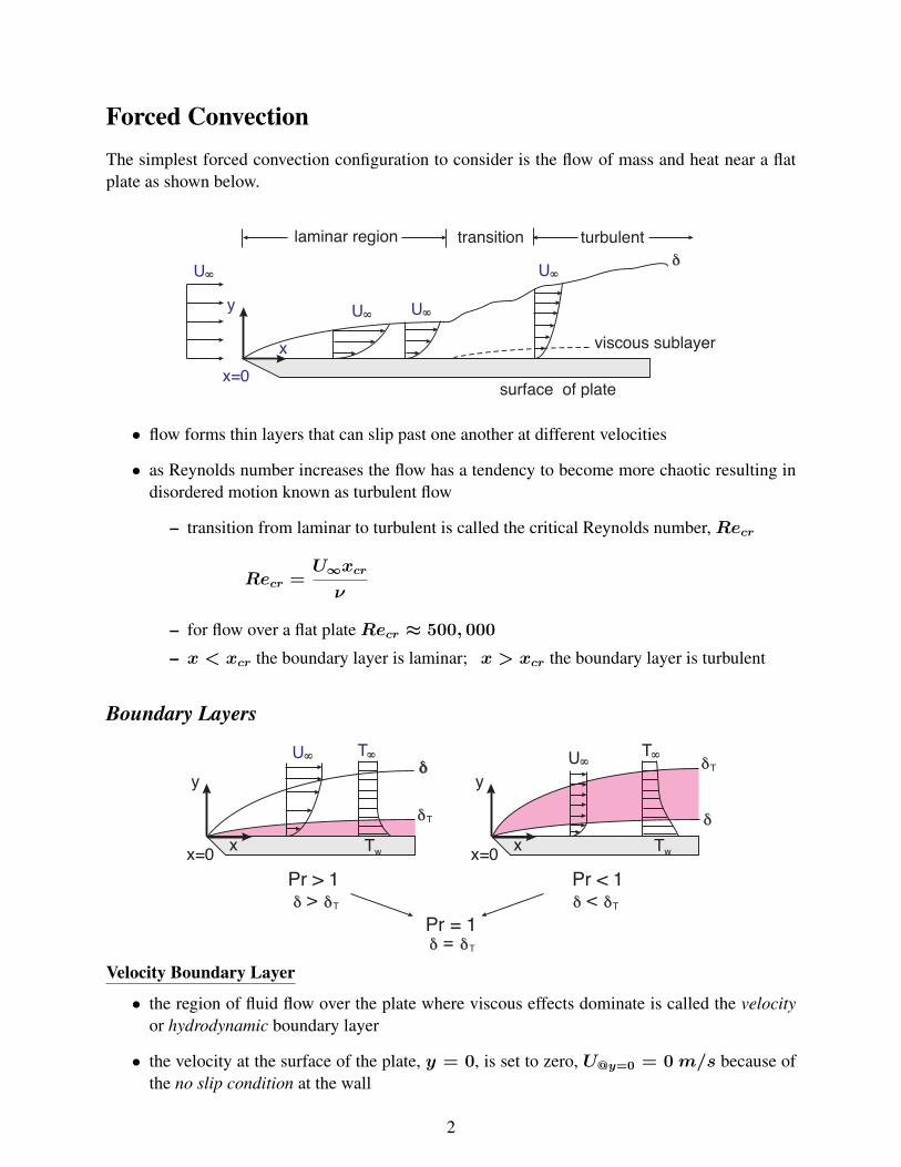
Forced ConvectionThe simplest forced convection configuration to consider is the flow of mass and heat near a flatplate as shown below.
• flow forms thin layers that can slip past one another at different velocities
• as Reynolds number increases the flow has a tendency to become more chaotic resulting indisordered motion known as turbulent flow
– transition from laminar to turbulent is called the critical Reynolds number,Recr
Recr =U∞xcr
ν
– for flow over a flat plateRecr ≈ 500, 000
– x < xcr the boundary layer is laminar; x > xcr the boundary layer is turbulent
Boundary Layers
Velocity Boundary Layer
• the region of fluid flow over the plate where viscous effects dominate is called the velocityor hydrodynamic boundary layer
• the velocity at the surface of the plate, y = 0, is set to zero, U@y=0 = 0 m/s because ofthe no slip condition at the wall
2

• the velocity of the fluid progressively increases away from the wall until we reach approxi-mately 0.99 U∞ which is denoted as the δ, the velocity boundary layer thickness.
• the region beyond the velocity boundary layer is denoted as the inviscid flow region, wherefrictional effects are negligible and the velocity remains relatively constant at U∞
Thermal Boundary Layer
• the thermal boundary layer is arbitrarily selected as the locus of points where
T − Tw
T∞ − Tw
= 0.99
• for low Prandtl number fluids the velocity boundary layer is fully contained within the ther-mal boundary layer
• conversely, for high Prandtl number fluids the thermal boundary layer is contained withinthe velocity boundary layer
Flow Over Plates
1. Laminar Boundary Layer Flow, Isothermal (UWT)
All laminar formulations forRe < 500, 000. The local value of the Nusselt number is given as
Nux = 0.332Re1/2x Pr1/3 ⇒ local, laminar, UWT, Pr ≥ 0.6
An average value of the heat transfer coefficient for the full extent of the plate can be obtained byusing the mean value theorem.
NuL =hLL
kf= 0.664 Re
1/2L Pr1/3 ⇒ average, laminar, UWT, Pr ≥ 0.6
For low Prandtl numbers, i.e. liquid metals
Nux = 0.565Re1/2x Pr1/2 ⇒ local, laminar, UWT, Pr ≤ 0.6
2. Turbulent Boundary Layer Flow, Isothermal (UWT)
All turbulent formulations for 500, 000 ≤ Re ≤ 107. The local Nusselt number is given as
Nux = 0.0296Re0.8x Pr1/3 ⇒
local, turbulent, UWT,0.6 < Pr < 60
3

and the average Nusselt number is
NuL = 0.037Re0.8L Pr1/3 ⇒
average, turbulent, UWT,0.6 < Pr < 60
3. Combined Laminar and Turbulent Boundary Layer Flow, Isothermal (UWT)
When (Tw − T∞) is constant
hL =1
L
∫ L
0hdx =
1
L
{∫ xcr
0hlam
x dx+∫ L
xcr
hturx dx
}
NuL =hLL
k= (0.037Re0.8
L − 871) Pr1/3 ⇒
average, combined, UWT,0.6 < Pr < 60,500, 000 ≤ ReL ≤ 107
4. Laminar Boundary Layer Flow, Isoflux (UWF)
Nux = 0.453Re1/2x Pr1/3 ⇒ local, laminar, UWF, Pr ≥ 0.6
5. Turbulent Boundary Layer Flow, Isoflux (UWF)
Nux = 0.0308Re4/5x Pr1/3 ⇒ local, turbulent, UWF, Pr ≥ 0.6
Example 6-1: Hot engine oil with a bulk temperature of 60 ◦C flows over a horizontal, flatplate 5 m long with a wall temperature of 20 ◦C. If the fluid has a free stream velocity of2 m/s, determine the heat transfer rate from the oil to the plate if the plate is assumed to beof unit width.
4

Flow Over Cylinders and Spheres
1. Boundary Layer Flow Over Circular Cylinders, Isothermal (UWT)
The Churchill-Bernstein (1977) correlation for the average Nusselt number forlong (L/D > 100) cylinders is
NuD = 0.3 +0.62Re
1/2D Pr1/3
[1 + (0.4/Pr)2/3]1/4
1 +
(ReD
282, 000
)5/84/5
⇒ average, UWT,ReD < 107, 0 ≤ Pr ≤ ∞, ReD · Pr > 0.2
All fluid properties are evaluated at Tf = (Tw + T∞)/2.
2. Boundary Layer Flow Over Non-Circular Cylinders, Isothermal (UWT)
The empirical formulations of Zhukauskas and Jakob given in Table 12-3 are commonly used,where
NuD ≈hD
k= C RemD Pr
1/3 ⇒ see Table 12-3 for conditions
3. Boundary Layer Flow Over a Sphere, Isothermal (UWT)
For flow over an isothermal sphere of diameterD, Whitaker recommends
NuD = 2 +[0.4Re
1/2D + 0.06Re
2/3D
]Pr0.4
(µ∞
µs
)1/4
⇒
average, UWT,0.7 ≤ Pr ≤ 380
3.5 < ReD < 80, 000
where the dynamic viscosity of the fluid in the bulk flow, µ∞ is based on the free stream tem-perature, T∞ and the dynamic viscosity of the fluid at the surface, µs, is based on the surfacetemperature, Ts. All other properties are based on T∞.
5
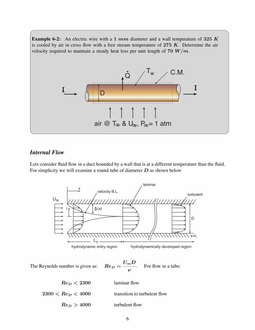
Example 6-2: An electric wire with a 1 mm diameter and a wall temperature of 325 Kis cooled by air in cross flow with a free stream temperature of 275 K. Determine the airvelocity required to maintain a steady heat loss per unit length of 70 W/m.
Internal Flow
Lets consider fluid flow in a duct bounded by a wall that is at a different temperature than the fluid.For simplicity we will examine a round tube of diameterD as shown below
The Reynolds number is given as: ReD =UmD
ν. For flow in a tube:
ReD < 2300 laminar flow
2300 < ReD < 4000 transition to turbulent flow
ReD > 4000 turbulent flow
6

For engineering calculations, we typically assume thatRecr ≈ 2300, therefore
ReD
{< Recr laminar> Recr turbulent
Hydrodynamic (Velocity) Boundary Layer
• when the boundary layer grows to the tube radius, r, the boundary layers merge
– this flow length is called the flow entrance length, Lh
– 0 ≤ x ≤ Lh is the hydrodynamic entrance region
– Lh < x ≤ L is the fully developed region or hydrodynamically developed region
• the hydrodynamic boundary layer thickness can be approximated as
δ(x) ≈ 5x
(Umx
ν
)−1/2
=5x√Rex
• the hydrodynamic entry length can be approximated as
Lh ≈ 0.05ReDD (laminar flow)
Thermal Boundary Layer
• a thermal entrance region develops from 0 ≤ x ≤ Lt
• the thermal entry length can be approximated as
Lt ≈ 0.05ReDPrD = PrLh (laminar flow)
• for turbulent flow Lh ≈ Lt ≈ 10D
7

Wall Boundary Conditions
1. Uniform Wall Heat Flux: The total heat transfer from the wall to the fluid stream can be deter-mined by performing an energy balance over the tube. If we assume steady flow conditions,min = mout = m then the energy balance becomes
Q = qwA = m(hout − hin) = mCp(Tout − Tin)
Since the wall flux qw is uniform, the localmean temperature is linear with x.
Tm,x = Tm,i +qwA
mCp
The surface temperature can be determinedfrom
Tw = Tm +qw
h
2. Isothermal Wall: Using Newton’s law of cooling we can determine the average rate of heattransfer to or from a fluid flowing in a tube
Q = hA (Tw − Tm)︸ ︷︷ ︸average ∆T
From an energy balance over a control volume in the fluid, we can determine
Q = mCpdTm
Equating the two equations above we find
mCpdTm = hA (Tw − Tm)︸ ︷︷ ︸average ∆T
By isolating the temperature terms and inte-grating we obtain
ln
(Tw − Tout
Tw − Tin
)= −
hA
mCp
Because of the exponential temperature decay within the tube, it is common to present themean temperature from inlet to outlet as a log mean temperature difference where
∆Tln =Tout − Tin
ln
(Tw − Tout
Tw − Tin
) =Tout − Tin
ln(∆Tout/∆Tin)⇒ Q = hA∆Tln
8

1. Laminar Flow in Circular Tubes, Isothermal (UWT) and Isoflux (UWF)
For laminar flow whereReD ≤ 2300
NuD = 3.66 ⇒ fully developed, laminar, UWT, L > Lt & Lh
NuD = 4.36 ⇒ fully developed, laminar, UWF, L > Lt & Lh
NuD = 1.86
(ReDPrD
L
)1/3 (µb
µs
)0.14
⇒
developing laminar flow, UWT,Pr > 0.5
L < Lh or L < Lt
For non-circular tubes the hydraulic diameter, Dh = 4Ac/P can be used in conjunction withTable 13-1 to determine the Reynolds number and in turn the Nusselt number.
2. Turbulent Flow in Circular Tubes, Isothermal (UWT) and Isoflux (UWF)
For turbulent flow whereReD ≥ 2300 the Dittus-Boelter equation (Eq. 13-68) can be used
NuD = 0.023Re0.8D Prn ⇒
turbulent flow, UWT or UWF,0.7 ≤ Pr ≤ 160
ReD > 2, 300
n = 0.4 heatingn = 0.3 cooling
For non-circular tubes, again we can use the hydraulic diameter,Dh = 4Ac/P to determine boththe Reynolds and the Nusselt numbers.
In all cases the fluid properties are evaluated at the mean fluid temperature given as
Tmean =1
2(Tm,in + Tm,out)
except for µs which is evaluated at the wall temperature, Ts.
9

Natural Convection
What Drives Natural Convection?• fluids tend to expand when heated and contract
when cooled at constant pressure
• therefore a fluid layer adjacent to a surface willbecome lighter if heated and heavier if cooledby the surface
• a lighter fluid will flow upward and a coolerfluid will flow downward
• as the fluid sweeps the wall, heat transfer willoccur in a similar manner to boundary layerflow however in this case the bulk fluid is sta-tionary as opposed to moving at a constant ve-locity in the case of forced convection
In natural convection, the Grashof number is analogous to the Reynolds number.
Gr =buouancy forceviscous force
=gβ(Tw − T∞)L3
ν2
Natural Convection Over Surfaces
• natural convection heat transferdepends on geometry and ori-entation
• note that unlike forced convec-tion, the velocity at the edge ofthe boundary layer goes to zero
• the velocity and temperatureprofiles within a boundary layerformed on a vertical plate ina stationary fluid looks as fol-lows:
10

Natural Convection Heat Transfer Correlations
The general form of the Nusselt number for natural convection is as follows:
Nu = f(Gr, Pr) ≡ CGrmPrn where Ra = Gr · Pr
• C depends on geometry, orientation, type of flow, boundary conditions and choice of char-acteristic length.
• m depends on type of flow (laminar or turbulent)
• n depends on the type of fluid and type of flow
• Table 14-1 should be used to find Nusselt number for various combinations of geometry andboundary conditions
– for ideal gases β = 1/Tf , (1/K)
– all fluid properties are evaluated at the film temperature, Tf = (Tw + T∞)/2.
1. Laminar Flow Over a Vertical Plate, Isothermal (UWT)
The general form of the Nusselt number is given as
NuL =hLkf
= C
gβ(Tw − T∞)L3
ν2︸ ︷︷ ︸≡Gr
1/4 ν
α︸︷︷︸≡Pr
1/4
= C Gr1/4L Pr1/4︸ ︷︷ ︸Ra1/4
where
RaL = GrLPr =gβ(Tw − T∞)L3
αν
2. Laminar Flow Over a Long Horizontal Circular Cylinder, Isothermal (UWT)
The general boundary layer correlation is
NuD =hD
kf= C
gβ(Tw − T∞)D3
ν2︸ ︷︷ ︸≡Gr
1/4 ν
α︸︷︷︸≡Pr
1/4
= C Gr1/4D Pr1/4︸ ︷︷ ︸Ra
1/4D
where
RaD = GrDPr =gβ(Tw − T∞)L3
αν
11
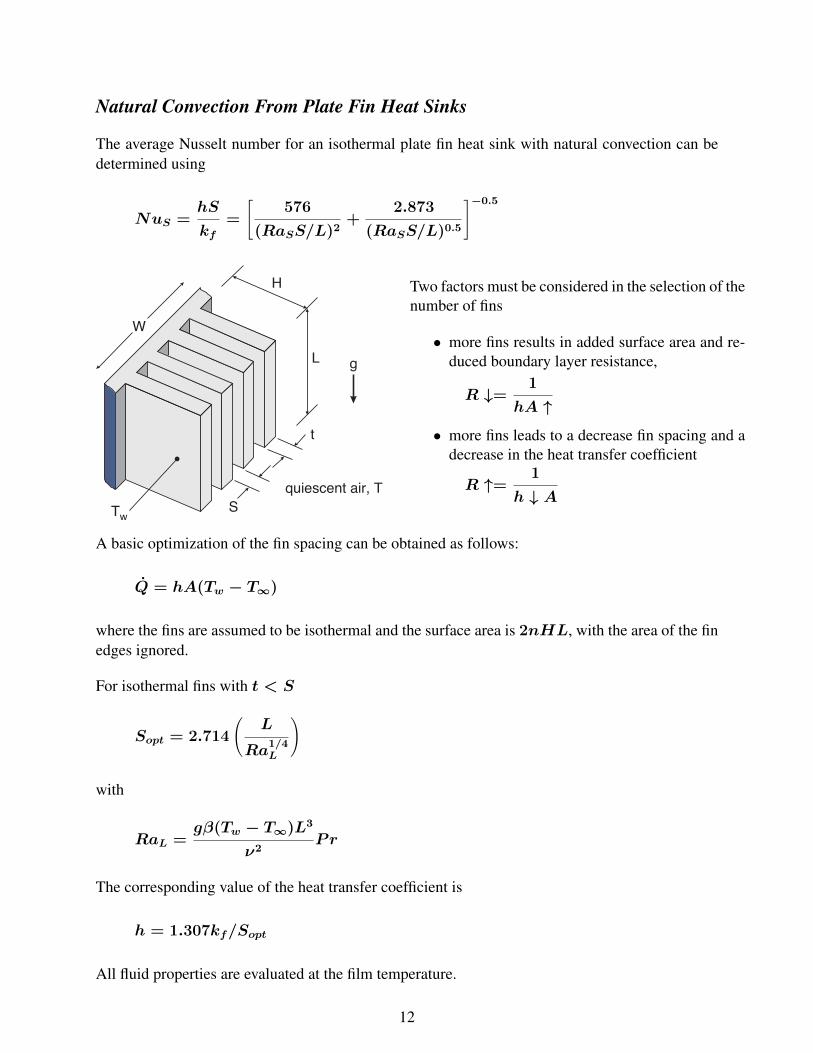
Natural Convection From Plate Fin Heat Sinks
The average Nusselt number for an isothermal plate fin heat sink with natural convection can bedetermined using
NuS =hS
kf=
[576
(RaSS/L)2+
2.873
(RaSS/L)0.5
]−0.5
Two factors must be considered in the selection of thenumber of fins
• more fins results in added surface area and re-duced boundary layer resistance,
R ↓=1
hA ↑
• more fins leads to a decrease fin spacing and adecrease in the heat transfer coefficient
R ↑=1
h ↓ A
A basic optimization of the fin spacing can be obtained as follows:
Q = hA(Tw − T∞)
where the fins are assumed to be isothermal and the surface area is 2nHL, with the area of the finedges ignored.
For isothermal fins with t < S
Sopt = 2.714
(L
Ra1/4L
)
with
RaL =gβ(Tw − T∞)L3
ν2Pr
The corresponding value of the heat transfer coefficient is
h = 1.307kf/Sopt
All fluid properties are evaluated at the film temperature.
12

Example 6-3: Find the optimum fin spacing, Sopt and the rate of heat transfer, Q for thefollowing plate fin heat sink cooled by natural convection.
Given:
W = 120 mm H = 24 mmL = 18 mm t = 1 mmTw = 80 ◦C T∞ = 25 ◦CP∞ = 1 atm fluid = air
Find: Sopt and the corresponding heat transfer, Q
13