Embed Size (px)
Citation preview
Conversion of Bioreactors to Continuous Perfusion Using Hollow Fiber Cell Separators
Practical Aspects
United States 800-634-3300 Europe 31-76-5719-419 Japan 81-77-552-7820China 86-21-68810228 copyright ©1989 all rights reserved
1
Contents 1. Introduction 2 1.1 Available Options for Conversion of a Bioreactor to Perfusion Operation 3
1.2 Results Obtained Using CellFlo Hollow Fiber Cell Separators for Converting Bioreactors to Continuous Perfusion 5
2. Basic Concepts of Crossflow Separation 6 3. Converting a Batch Bioreactor to Perfusion Using CellFlo Separators 7 3.1 Bioreactor With Steam Supply for Sterilization 8 3.1.1 The Basic System Startup 8 3.1.2 Component Parts 8 3.1.3 Bioreactor Modifications and Preparations 10 3.1.4 System Setup Procedure 11 3.2 Alternate System Configurations 12 3.2.1 Fewer Valves 12 3.2.2 Dual CellFlo Setup 12 3.2.3 Stainless Tubing Setup 13 3.3 Bioreactor Without Steam Supply for Sterilization 13 3.4 Pump and Tubing Recommendations 14 4. Operating Considerations 15 4.1 Perfusion Process Optimization 15 4.1.1 Daily Perfusion Rate 15 4.1.2 Recirculation Rate 17 4.1.3 Changing of the CellFlo Modules 19 4.1.4 Bioreactor Volume Control 19 4.1.5 Cell Harvesting 19 4.1.6 Serum 20 4.1.7 Antifoams and Surfactants 21 4.1.8 Backflushing and Optional Media Feeding Strategies 22 4.1.9 Sterility Protection 23 5. Sterilization and Sanitization 24 5.1 Sterilization 24 5.1.1 Autoclaving a Perfusion Loop Containing a CellFlo Module 24 5.1.2 Chemical Sanitization 25 6. Integrity Testing 25 6.1. Wetting the CellFlo Module 25 6.1. Pressure Hold Test 27 6.1. Diffusion and Bubble Point Tests 27 7. References 28
2
1. Introduction Historically, most pharmaceutical fermentation products have been derived from bacteria and fungi grown in stirred tank fermenters ranging in size up to tens of thousands of liters. With the advent of recombinant DNA techniques in the mid 1970s and the emergence of the biotechnology industry in the late 1970s, it was assumed that production of the new class of pharmaceuticals would be done in the same fermenters. As the first recombinant products were being produced in bacteria, it was discovered that many of them were not biologically active. The lack of activity is related to the inability of procaryotic cells to post-translationally modify mammalian derived proteins correctly.
At the same time, monoclonal antibodies were recognized as having powerful diagnostic and therapeutic potential. The fused hybridoma cells that produce monoclonal antibodies are also mammalian derived cells. Thus, a large proportion of the new generation of biopharmaceuticals for diagnostic and therapeutic applications is now being produced in mammalian cells (1).
The long history of pharmaceutical production in fermenters and a lack of bioreactors custom designed for mammalian cells, has led to interest in converting existing stirred-tank bacterial fermenters into mammalian cell bioreactors (2-4). Most microbial fermenters are designed for batch operation. Batch operation of a microbial fermenter is economical due to high cell densities (>109 cells/ml), rapid doubling times (-20 min for many bacteria) and to the hardy nature of the cells, which allows the use of aggressive agitation and gassing. Typical microbial batch operations last 5-10 days. In this short period of time, vast quantities of product can be produced.
Mammalian cells, on the other hand, grow to densities 10-1000 times lower than bacterial cells, even under the most optimal conditions. They have doubling times in the range of 18-36 hours, much more complex nutritional requirements than microbial cells and they are far more sensitive to minor perturbations in their environment. A mammalian cell culture operated in a 5-10 day batch mode will only reach reasonable densities near the end of the run, so product yields are generally low. Variations of batch operation (such as fed-batch or semi-continuous batch) can improve the run length, cell density and productivity, but are still far from optimal.
Therefore, optimization of bioreactor designs and culture processes for mammalian cells is a high priority within the biopharmaceutical industry (4). Optimization efforts share common goals; maximizing cell density, cell viability, productivity per cell and culture length. To achieve these goals, all aspects of the culture process must be examined and carefully controlled. Factors to be considered include cell line construction, culture media formulations, feeding strategies, bioreactor system design and process control strategies (4,5).
3
There are three basic reasons for converting bacterial fermenters into mammalian cell bioreactors. First, there is a long history of use of stirred tanks and their design and operation are well understood. Second, there are a large number of fermenters being used for bacterial production that can be converted to mammalian cell production, resulting in enormous capital equipment savings. Third, many custom designed mammalian cell culture bioreactors have been reported as being non-scalable for use as production systems. Modifications to existing fermenter designs to convert them to mammalian cell bioreactors include tank design, impeller design, impeller drive design, gas transfer system design and pH and DO controller designs. In addition to hardware designs, changes are being made to the culture process itself.
Optimization of mammalian cell production requires a high degree of control over the extracellular environment and the ability to run batches for several weeks. Control of the extracellular environment is possible with continuous perfusion culture (6-11). In perfusion culture, fresh media is continuously delivered to the cells and waste products are removed. Under these conditions, mammalian cells grow to densities as much as ten-fold higher than in batch or fed-batch culture, leading to proportional increases in production. The higher cell densities also result in reduced serum dependence, thus lowering operating and purification costs (11).
1.1 Available Options for Conversion of a Bioreactor to Perfusion Operation
A chemostat-like environment can be achieved by simply pumping the contents of the bioreactor to a harvest bottle while also feeding, but this technique removes cells and dilutes the culture, severely limiting the cell density and thus, total production. The optimal continuous perfusion process is one where the cells are retained within the bioreactor, while fresh media is added and waste media is removed, allowing higher cell densities and production.
Retention of cells within the bioreactor requires a separation process of some type. Methods for converting fermenters to continuous perfusion bioreactors include the use of disc filters, spin filters, flat sheet filters and hollow fiber filters. Due to the cell density and the presence of cell debris, filters used for continuous perfusion clog or foul after a period of time. As a result, in order to maintain continuous perfusion, the filter must be replaceable while the system is operating.
There are two options for connecting a perfusion filtration system to the bioreactor. It can be mounted inside or outside the bioreactor.
4
Spin filters and hollow fiber filters have the proper dimensional char-acteristics to fit within most bioreactors. Flat sheet and hollow fiber filters can be mounted outside the bioreactor and connected to the bioreactor via an external recirculation loop. There are advantages and disadvantages to both types of setups. Placement of the filter inside the bioreactor eliminates the need for pumps to move the bioreactor contents through the filter and return them to the bioreactor. The disadvantage of this setup is that there is no access to the filter once the culture is started. If there are any problems with the filtration setup (such as clogging), the bioreactor must be shut down, ending the production run. In addition, spin filters are specialized devices that require modifications to the impeller and headplate of the bioreactor which can require custom engineering. External filtration setups on the other hand, connect to the bioreactor through existing ports and do not require specialized hardware. They do require that the cells be pumped through an external loop. An external perfusion filter can be changed if it becomes clogged (or other problems occur), allowing long term continuous operation.
Optimal performance of a perfusion filtration system requires efficient retention of cells within the bioreactor, a compact and convenient filtration system that can be readily changed when it becomes clogged and a membrane porosity sufficiently large to allow removal of the desired secreted product as part of the perfusion process. Low product residence time minimizes exposure to pro-teases, reduces the potential for feedback inhibition and improves overall product stability (9).
Of the various filtration options available, microporous hollow fiber filters best meet the requirements for optimal performance of a perfusion filtration system. They have a high filter surface area to volume ratio, are compact, easily incorporated into a fluid loop configuration and can be changed during a run if necessary. A filter with 0.2-0.45um pore size will allow high flux rates, large volume throughput and the continuous harvest of spent media containing cell-free product. Since the harvest is cell free, the initial cell separa-tion step is eliminated. Thus, simplifying downstream purification. In addition, a continuous cell-free harvest is compatible with existing continuous affinity purification techniques.
Spectrum Labs has developed the CellFlo™ line of hollow fiber cell separators specifically for the conversion of stirred or airlift bioreactors to continuous perfusion. CellFlo modules utilize large internal diameter membranes, which allow recirculation of cells without damage and reduce clogging by cell debris. CellFlo modules are available in a variety of surface areas from 800 cm2 to 3.3 m2.
1.2 Results Obtained Using CellFlo Hollow Fiber Cell Separators for Converting Bioreactors to Continuous Perfusion
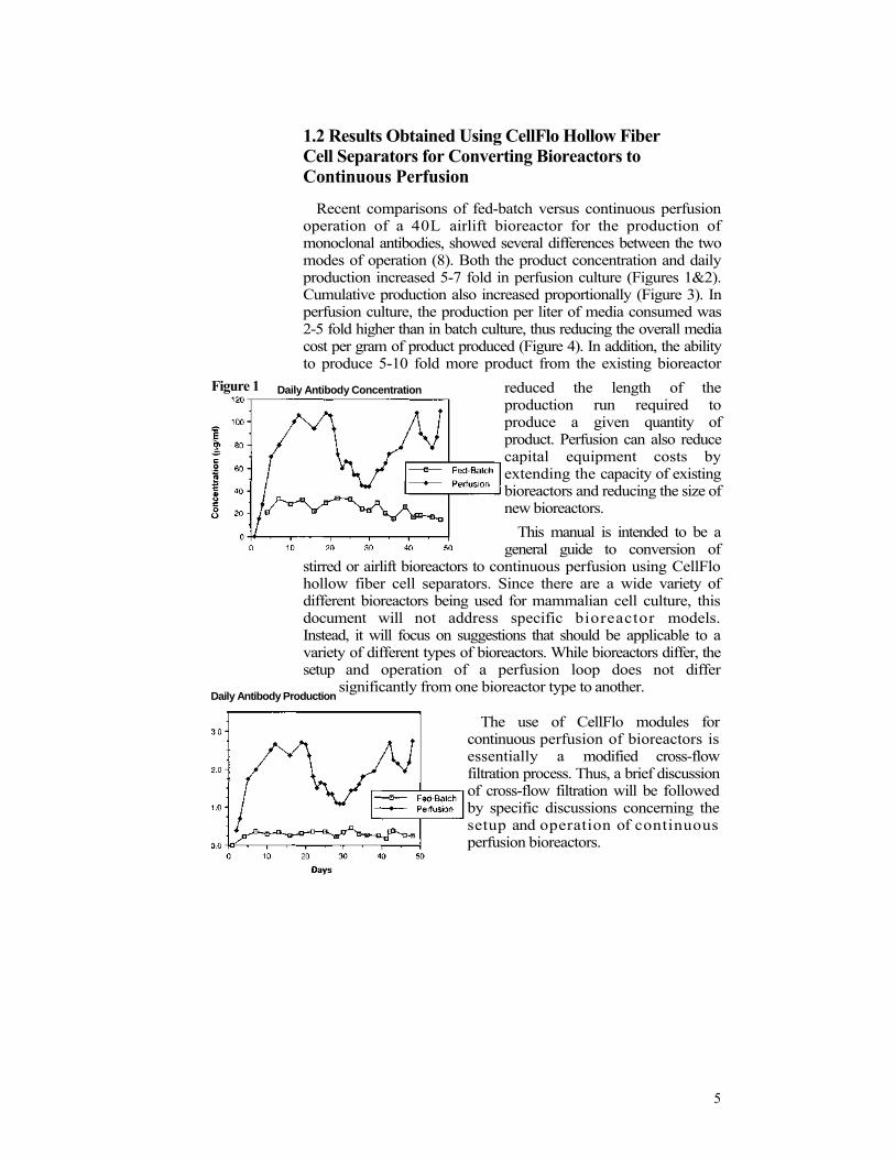
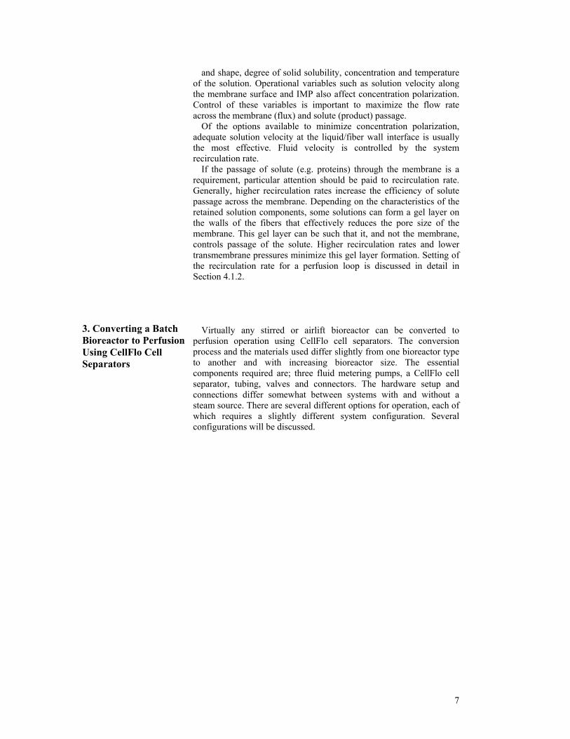
Recent comparisons of fed-batch versus continuous perfusion operation of a 40L airlift bioreactor for the production of monoclonal antibodies, showed several differences between the two modes of operation (8). Both the product concentration and daily production increased 5-7 fold in perfusion culture (Figures 1&2). Cumulative production also increased proportionally (Figure 3). In perfusion culture, the production per liter of media consumed was 2-5 fold higher than in batch culture, thus reducing the overall media cost per gram of product produced (Figure 4). In addition, the ability to produce 5-10 fold more product from the existing bioreactor
reduced the length of the production run required to produce a given quantity of product. Perfusion can also reduce capital equipment costs by extending the capacity of existing bioreactors and reducing the size of new bioreactors.
This manual is intended to be a general guide to conversion of
stirred or airlift bioreactors to continuous perfusion using CellFlo hollow fiber cell separators. Since there are a wide variety of different bioreactors being used for mammalian cell culture, this document will not address specific bioreactor models. Instead, it will focus on suggestions that should be applicable to a variety of different types of bioreactors. While bioreactors differ, the setup and operation of a perfusion loop does not differ
significantly from one bioreactor type to another.
Daily Antibody ConcentrationFigure 1
The use of CellFlo modules for continuous perfusion of bioreactors is essentially a modified cross-flow filtration process. Thus, a brief discussion of cross-flow filtration will be followed by specific discussions concerning the setup and operation of continuous perfusion bioreactors.
5
Daily Antibody Production

2. Basic Concepts of Crossflow Separation
Traditional filtration (or "dead-ended" filtration as it is often called), is a pressure driven separation. It consists of forcing a solution containing suspended solids directly through a filter material such as a membrane or filter pad. Solids are retained and generally collect al or near the surface of the filter, continually reducing the filtration rate and eventually leading to filter plugging (Figure 5).
Crossflow (or tangential-flow filtration) is a far more efficient means of separating suspended solids from a solution because the bulk of the solution flow is parallel to the filter surface rather than perpendicular to it. The most common forms of tangential flow filtration are stacked plate and spiral wound flat sheet membrane devices and hollow fiber devices. Hollow fiber membranes have been found to be more efficient due to their uniform tubular flow geometry (see ref. 12 for review).
Figure 3
Cumulative Production During operation of the module, solution is pumped in a recirculating loop through the inside of the fiber (lumen)(Figure 6). Trans-membrane pressure (TMP) is generated across the fiber membrane walls. The filtration process is driven by the TMP. In microfiltration, solids larger than the rated pore size of the filter are quantitatively held back by the membrane, while soluble components pass through the membrane walls along with the fluid. Filtration through the fiber membrane's walls results in a concentration build up of retained components near the fiber's internal membrane surface. Ideally, these components are carried down the length of the fiber and out the end of the module by the sweeping action of the recirculating fluid. However, under certain conditions, a gel or cake-like layer can accumulate on the internal surface of the membranes. This boundary layer is composed of solids and/or solute macromolecules which arc retained by the membrane during the filtration process. This phenomenon is termed "concentration polarization" and its formation affects module performance.
Figure 4 Production Per Liter of Media Consumed
The extent of concentration polarization is influenced by such variables as particle size
6
and shape, degree of solid solubility, concentration and temperature of the solution. Operational variables such as solution velocity along the membrane surface and IMP also affect concentration polarization. Control of these variables is important to maximize the flow rate across the membrane (flux) and solute (product) passage.
Of the options available to minimize concentration polarization, adequate solution velocity at the liquid/fiber wall interface is usually the most effective. Fluid velocity is controlled by the system recirculation rate.
If the passage of solute (e.g. proteins) through the membrane is a requirement, particular attention should be paid to recirculation rate. Generally, higher recirculation rates increase the efficiency of solute passage across the membrane. Depending on the characteristics of the retained solution components, some solutions can form a gel layer on the walls of the fibers that effectively reduces the pore size of the membrane. This gel layer can be such that it, and not the membrane, controls passage of the solute. Higher recirculation rates and lower transmembrane pressures minimize this gel layer formation. Setting of the recirculation rate for a perfusion loop is discussed in detail in Section 4.1.2.
3. Converting a Batch Bioreactor to Perfusion Using CellFlo Cell Separators
Virtually any stirred or airlift bioreactor can be converted to perfusion operation using CellFlo cell separators. The conversion process and the materials used differ slightly from one bioreactor type to another and with increasing bioreactor size. The essential components required are; three fluid metering pumps, a CellFlo cell separator, tubing, valves and connectors. The hardware setup and connections differ somewhat between systems with and without a steam source. There are several different options for operation, each of which requires a slightly different system configuration. Several configurations will be discussed.
7
8
3.1 Bioreactor With Steam Supply for Sterilization
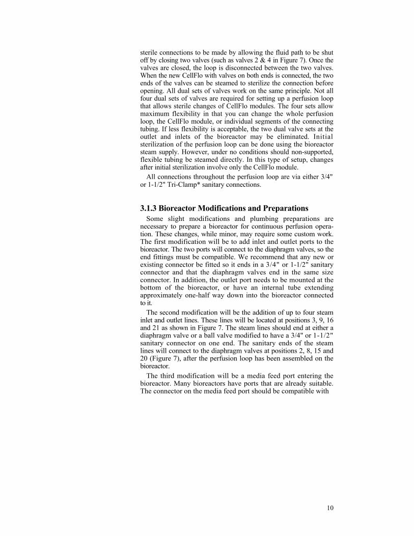
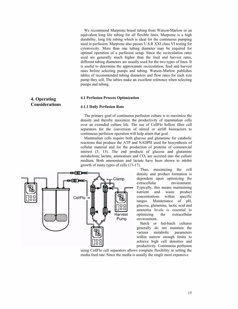
3.1.1 The Basic System Setup A basic system setup is illustrated in Figure 7. The essential com-ponents are the bioreactor, tubing for recirculation, the CellFlo module, sanitary valves for aseptic connection of the loop to the bioreactor, a media feed line, a harvest line and three pumps. The system illustrated is one of numerous possible setup configurations, depending upon the needs and desires of the end-user. This setup was designed to meet GMP requirements and to simplify the setup and on-line changing of CellFlo modules. The various individual components of the loop will be identified in order going around the perfusion loop. An explanation of the setup procedure will follow the discussion of component parts.
3.1.2 Component Parts 1. Bioreactor. Any stirred or airlift will do. Bioreactor size will affect the size of the tubing and the CellFlo module used but not other components. 2. Diaphragm valve. Sanitary valve with access port for steam inlet. 3. Small diaphragm valve. Valve for steam inlet or outlet at the connection point. 4. Diaphragm valve. Second valve to serve as a sterile disconnection point for the entire perfusion loop. 5. Small diaphragm valve. For steam inlet or outlet. 6. Flexible pump tubing (suitable for extended operation). 7. Flowmeter with digital readout (optional). To monitor the recirculation rate. 8. Diaphragm valve. For on-line sterile connection of replacement CellFlo modules.
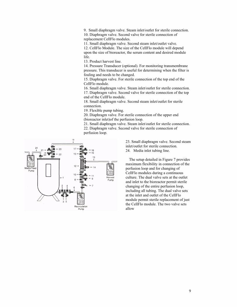
9. Small diaphragm valve. Steam inlet/outlet for sterile connection. 10. Diaphragm valve. Second valve for sterile connection of replacement CellFlo modules. 11. Small diaphragm valve. Second steam inlet/outlet valve. 12. CellFlo Module. The size of the CellFlo module will depend upon the size of bioreactor, the serum content and desired module life. 13. Product harvest line. 14. Pressure Transducer (optional). For monitoring transmembrane pressure. This transducer is useful for determining when the filter is fouling and needs to be changed. 15. Diaphragm valve. For sterile connection of the top end of the CellFlo module. 16. Small diaphragm valve. Steam inlet/outlet for sterile connection. 17. Diaphragm valve. Second valve for sterile connection of the top end of the CellFlo module. 18. Small diaphragm valve. Second steam inlet/outlet for sterile connection. 19. Flexible pump tubing. 20. Diaphragm valve. For sterile connection of the upper end (bioreactor inlet)of the perfusion loop. 21. Small diaphragm valve. Steam inlet/outlet for sterile connection. 22. Diaphragm valve. Second valve for sterile connection of perfusion loop.
23. Small diaphragm valve. Second steam inlet/outlet for sterile connection. 24. Media inlet tubing line.
The setup detailed in Figure 7 provides
maximum flexibility in connection of the perfusion loop and for changing of CellFlo modules during a continuous culture. The dual valve sets at the outlet and inlet to the bioreactor permit sterile changing of the entire perfusion loop, including all tubing. The dual valve sets at the inlet and outlet of the CellFlo module permit sterile replacement of just the CellFlo module. The two valve sets allow
9
10
sterile connections to be made by allowing the fluid path to be shut off by closing two valves (such as valves 2 & 4 in Figure 7). Once the valves are closed, the loop is disconnected between the two valves. When the new CellFlo with valves on both ends is connected, the two ends of the valves can be steamed to sterilize the connection before opening. All dual sets of valves work on the same principle. Not all four dual sets of valves are required for setting up a perfusion loop that allows sterile changes of CellFlo modules. The four sets allow maximum flexibility in that you can change the whole perfusion loop, the CellFlo module, or individual segments of the connecting tubing. If less flexibility is acceptable, the two dual valve sets at the outlet and inlets of the bioreactor may be eliminated. Initial sterilization of the perfusion loop can be done using the bioreactor steam supply. However, under no conditions should non-supported, flexible tubing be steamed directly. In this type of setup, changes after initial sterilization involve only the CellFlo module.
All connections throughout the perfusion loop are via either 3/4" or 1-1/2" Tri-Clamp* sanitary connections.
3.1.3 Bioreactor Modifications and Preparations Some slight modifications and plumbing preparations are
necessary to prepare a bioreactor for continuous perfusion opera-tion. These changes, while minor, may require some custom work. The first modification will be to add inlet and outlet ports to the bioreactor. The two ports will connect to the diaphragm valves, so the end fittings must be compatible. We recommend that any new or existing connector be fitted so it ends in a 3/4" or 1-1/2" sanitary connector and that the diaphragm valves end in the same size connector. In addition, the outlet port needs to be mounted at the bottom of the bioreactor, or have an internal tube extending approximately one-half way down into the bioreactor connected to it.
The second modification will be the addition of up to four steam inlet and outlet lines. These lines will be located at positions 3, 9, 16 and 21 as shown in Figure 7. The steam lines should end at either a diaphragm valve or a ball valve modified to have a 3/4" or 1-1/2" sanitary connector on one end. The sanitary ends of the steam lines will connect to the diaphragm valves at positions 2, 8, 15 and 20 (Figure 7), after the perfusion loop has been assembled on the bioreactor.
The third modification will be a media feed port entering the bioreactor. Many bioreactors have ports that are already suitable. The connector on the media feed port should be compatible with
11
whatever is being used for the media feed line. A dual valve setup like the rest of the ports may be desirable to allow for sterile changes of the media feed line.
3.1.4 System Setup Procedure The exact setup procedure used will depend upon the configura-
tion of the perfusion loop. The procedure outlined here will assume a configuration similar to that in Figure 7.
1. Assemble a CellFlo module with a diaphragm valve connected to both ends, with a pressure transducer and harvest line connected to the filtrate ports as shown in Figure 7. See section 5 for additional information concerning preparation and sterilization of CellFlo modules.
2. Assemble the rest of the perfusion loop. This will require two lengths of tubing with diaphragm valves at both ends. The tubing should be long enough to permit connection of the CellFlo to the inlet and outlet ports on the bioreactor.
3. Connect diaphragm valves to the inlet and outlet ports on the bioreactor.
4. Autoclave the CellFlo with the two valves and the two tubing segments attached (#s 4,6,8,10,12,13,14,15,17,19,20 in Figure 7). All valves should be covered but open.
5. After autoclaving, remove all components to a laminar flow hood, allow them to cool, then close all valves.
6. Once the components have all cooled to room temperature, the perfusion loop can be connected to the bioreactor.
7. Once the perfusion loop is connected, all connection points must be sterilized. Open the steam inlet and outlet valves at all connections (3, 9, 16 and 21 in Figure 7) and steam the connections for 30-60 min.
8. Shut off all steam valves (3, 9, 16 and 21 in Figure 7). Allow all valves to cool to room temperature.
9. Prepare the perfusion loop for operation. Load the tubing into the recirculation pump. Open all valves within the recirculation loop (2, 4, 8, 10, 15, 17, 20 and 22 in Figure 7).
10. Start the recirculation pump, media feed and harvest pumps. If the extracapillary space of the CellFlo does not fill with media, restrict the outlet end of the recirculation loop briefly, or close valve #15 until the extracapillary space fills, then re-open the restriction or the valve.

3.2 Alternate System Configurations 3.2.1 Fewer Valves
If the number of valves and steam lines required for the setup
described above is more than desired, an alternative setup can be used. While it is less expensive and simpler, it is also less flexible. This configuration is illustrated in Figure 8. It differs from Figure 7 in that the valves on either end of the CellFlo have been eliminated. Thus,
the entire perfusion loop is a single entity. When installing this unit, the complete loop is assembled and sterilized intact. It is connected to the valves at the inlet and outlet of the bioreactor. When changing Cell-Flo modules, the entire loop is removed. When this method is used, it is convenient to have a second fully configured perfusion loop available to minimize the time required for CellFlo changes. Without a second loop, the first will need to be cleaned, the CellFlo changed and the complete loop re-sterilized while the recirculation pump is shut off.
3.2.2 Dual CellFlo Setup
While several types of configurations are
possible and will work equally well, we will discuss one other configuration which is particularly useful. This configuration is useful in several situations; for larger bioreactors where the throughput is too great for a single module, for changing of modules without shutting off the perfusion loop, or for both feeding and harvesting through CellFlo modules. The system illustrated in Figure 9 contains two CellFlo modules. Additional components required are two "Tee" fittings, two dual valve set-ups connected to a CellFlo module and a second pressure transducer
12
13
.
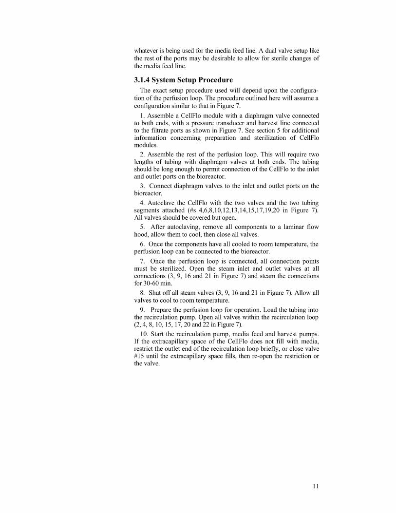
(optional). In this configuration, both CellFIo modules may be operated individually or simultaneously. Alternatively, one CellFIo may be used for feeding media into the bioreactor while the other is used for harvesting (Figure 10). With the addition of a programmable timer, the feed and harvest CellFIo can be alternated such that each module is used for feeding for a period of time, then it can be switched automati-cally to harvesting using the timer and electronic valves (not shown). This operation option serves to backflush the CellFIo, potentially extending its useful life (see section 4.1.8 for additional discussion of backflushing)
3.2.3 Stainless Tubing Setup
As a variation to the setups illustrated in Figures 7-10, most of the
perfusion loop can also be hard plumbed with stainless steel tubing so that the only segment of flexible tubing is the one passing through the peristaltic pump. In this configuration, one or both of the diaphragm valves at the inlet and outlet (#s 2, 4, 20, 22 in Figure 7) of the bioreactor can be eliminated. Instead, the steam supply to the bioreactor can be used to sterilize the stainless lines. The steam outlet in this case becomes the steam out on the valve set on the CellFIo (#11 in Figure 7). This configuration requires valve sets at either end of the Cellflo for changing modules. One complication to this setup is the pump tubing. The tubing must be suitable for steam service and adequately shrouded to protect personnel. Otherwise, a bypass must be incorporated for steaming the stainless tubing. In addition, when a bypass is used, an alternate method to sterilize the flexible tubing must be used.
3.3 Bioreactor Without Steam Supply for Sterilization
Most bioreactors up to about 20L in size are not connected to steam.
With these types of bioreactors, connections must be made aseptically. We have had success using the configuration illustrated in Figure 11. The perfusion loop has all the same basic components as the loop for larger systems. However, the loop for a non-steam system generally uses only flexible tubing, it is smaller in diameter and most, if not all, connections are hose barb, rather than sanitary fittings. Since this type of perfusion loop cannot be sterilized after
making connections, all CellFlo changes must be made aseptically. We have also had success using stainless steel Swagelok quick connects with double end shutoffs at all connection points (Figure 11}. The bodies of the quick disconnects are connected via bulkhead Swagelok tube connectors to the inlet and outlet ports of the bioreactor. The sterns are connected to the recirculation loop tubing via a hose barb connector double end shutoff stem. Sterile connection of the recirculation loop is accomplished by flame sterilization of both ends of the quick disconnect just prior to assembly. Replacement of a recirculation loop requires disconnecting the old loop, flame sterilization of the old body and the new stem simultaneously, as the two are being connected. This procedure allows connections to be made in an open laboratory environment with a relatively high degree of confidence.
Setup of this system consists of assembly of all the components of the perfusion loop and then connection to the bioreactor. The entire bioreactor and perfusion loop arc autoclaved together at the same time. CellFlo changes occur at the Swagelok connectors.
As an alternative, two CellFlo modules can be assembled into the perfusion loop in parallel using "Y" fittings (Figure 12}. One CellFlo can be clamped off while the other is used. Once the first unit fouls, the second unit can be opened and the first clamped off. A dual CellFlo setup like this will often allow the perfusion culture to operate for several weeks, which is sufficient for most production runs.
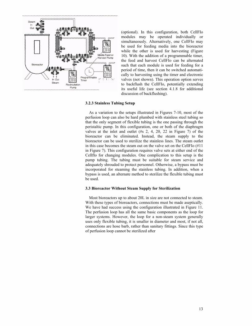
3.4 Pump and Tubing Recommendations
Recirculating cells through an external loop requires the use of a
pump. Many types of pumps are available for the movement of fluids. We recommend a low-shear pump whenever possible (for a dis-
cussion of shear effects sec section 4.1.2). While peristaltic pumps are not necessarily low shear, they are common and readily available. If peristaltic pumps are used, we recommend Watson-Marlow peristaltic pumps for all bioreactors up to 100 liters. These pumps have spring loaded rollers, which allow adjustment of the tension on the tubing. Watson-Marlow pumps are available in a variety of sizes, with different maximum flow rates. Selection of pump size will depend upon the size of the bioreactor and the desired flow rate.
14
We recommend Marprene brand tubing from Watson-Marlow or an equivalent long life tubing for all flexible lines. Marprene is a high durability, long life tubing which is ideal for the continuous pumping used in perfusion. Marprene also passes U.S.R XXI class VI testing for cytotoxicity. More than one tubing diameter may be required for optimal operation of a perfusion setup. Since the recirculation rates used are generally much higher than the feed and harvest rates, different tubing diameters are usually used for the two types of lines. It is useful to determine the approximate recirculation, feed and harvest rates before selecting pumps and tubing. Watson-Marlow publishes tables of recommended tubing diameters and flow rates for each size pump they sell. The tables make an excellent reference when selecting pumps and tubing.
4.1 Perfusion Process Optimization 4. Operating Considerations
4.1.1 Daily Perfusion Rate
The primary goal of continuous perfusion culture is to maximize the
density and thereby maximize the productivity of mammalian cells over an extended culture life. The use of CellFlo hollow fiber cell separators for the conversion of stirred or airlift bioreactors to continuous perfusion operation will help attain that goal.
Mammalian cells require both glucose and glutamine for catabolic reactions that produce the ATP and NADPH used for biosynthesis of cellular material and for the production of proteins of commercial interest (5, 13). The end products of glucose and glutamine metabolism; lactate, ammonium and CO2 are secreted into the culture medium. Both ammonium and lactate have been shown to inhibit growth of many types of cells (13-17).
Thus, maximizing the cell density and product formation is dependent upon optimizing the extracellular environment. Typically, this means maintaining nutrient and waste product concentrations within specific ranges. Maintenance of pH, glucose, glutamine, lactic acid and ammonia levels is essential to optimizing the extracellular environment.
Batch or fed-batch cultures generally do not maintain the various metabolic parameters within narrow enough limits to achieve high cell densities and productivity. Continuous perfusion
using CellFlo cell separators allows complete flexibility in setting the media feed rate. Since the media is usually the single most expensive
15
16
item used in the production of proteins from mammalian cells, mini-mizing media usage is essential for economical production. The single biggest challenge in optimizing production of mammalian cell-derived biologicals is trying to balance the need to maintain a proper nutrient environment within the bioreactor with the need to minimize media usage.
Traditional methods of maintaining adequate levels of glucose, glutamine and pH, while simultaneously minimizing ammonia and lactate levels, involve simple dilution with media. More recent attempts at optimization involve the selective addition of glucose, glutamine and base to cultures. The goal in this case is to maintain proper levels of energy sources and pH while minimizing lactate and ammonia production (1, 8, 18, 19). Addition of these metabolites is supplemental to a regular media feed. Effective optimization of media usage thus requires very close monitoring of all essential metabolites.
When setting up a continuous perfusion culture, a media feed rate needs to be established. The optimal rate depends upon a number of factors such as; the cell line, the media, the percentage of serum used and the tolerance level of the cell line to ammonium and lactate. It also depends upon whether glucose, glutamine, ammonium and lactate will be monitored and whether specific addition of glucose, glutamine and base is feasible. A simple way to discuss the media feed rate used in continuous perfusion cultures is to equate the rate to bioreactor volumes per day. The daily perfusion rate has been shown to have a significant effect on both the viable cell count and the percent viability of a culture (14). These studies were done using media perfusion only, without specific addition of glucose, glutamine or base. The results suggest that perfusion rates of 0.8 bioreactor volumes per day or greater are necessary to maintain both the percent viability and specific cell growth rate. If specific metabolite additions are used successfully, it can be assumed that lower perfusion rates will probably be effective.
Determining optimal perfusion and metabolite addition rates requires considerable experimentation with a specific cell line. Is there a perfusion rate that can be used that will work for most cell lines? Yes. Most cell lines will increase 5-10 fold in cell density and productivity if a perfusion rate of one bioreactor volume per day is used. Higher or lower rates may be needed for certain cell lines, but one volume/day is a good place to start. If glucose levels are found to be too low or lactic acid and ammonia levels are too high, higher perfusion rates may be necessary. If glucose levels are high and lactic acid and ammonia levels are low, lower perfusion rates can probably be used.

17
4.1.2 Recirculation Rate
The recirculation rate of the cells and media through the CellFlo separator is dependent upon the size of the bioreactor. As discussed in Section 2, optimal crossflow filtration generally occurs at high recirculation rates. It is also desirable to maximize the life of the cell separator so that the number of CellFlo changes during the culture run is minimized. These factors must be balanced with the desire to maintain a high cell viability within the culture. Generally, high recirculation rates are detrimental to cells. Thus, the recirculation rate used is a compromise between two considerations.
The limiting factor in setting the recirculation rate is the shear sensitivity of the cell line. All cell lines have different sensitivities to shear. Three major sources of shear are present within stirred or airlift cultures operated in perfusion mode using peristaltic pumps. They are; the agitation system, the gassing system and the pump/ perfusion loop. In stirred cultures, the agitation system is usually an impeller of some type. Most mammalian cell bioreactors have impellers designed to impart low shear stress, but the actual shear generated varies considerably. Airlift bioreactors rely on a column of rising air to provide agitation and gassing. Air bubbles in a culture generate shear at the air/liquid interface. Most stirred and airlift bioreactors utilize some degree of sparging for oxygenation of cultures. Sparging also contributes to shear on the cells. In addition, higher density cultures require proportionally more oxygen. If sparging is the main source of oxygen to the culture, then higher densities require increased sparging, which increases the shear on the cells. The third source of shear in a perfusion culture is the external perfusion loop. The shear stress in the perfusion loop is directly proportional to the recirculation rate of the culture fluid. It is also influenced by the diameter of the tubing used for the loop and the RPM of the pump. The use of larger diameter tubing and lower RPM settings results in lower shear at any given flow rate. We rec-ommend relatively large diameter tubing and high capacity pumps for setting up perfusion loops.
Recent studies have examined the effects of shear on mammalian cells being pumped through an external recirculation loop setup containing a hollow fiber cell separator (20). The setup was similar to that used for continuous perfusion of stirred or airlift bioreactors. These studies showed that cells can tolerate wall shear rates up to 3000 sec ' before loss of viability occurs. For time-independent, laminar, newtonian fluid flow in a circular tube (fiber), the shear rate {¥) can be expressed as:

¥ = 4Q/;π r3 = 8Vav/D (21 -23) (Eq. 4.1,2-A) where: Q = flow rate r - radius of the fiber V.iv = average fluid velocity D = diameter of the fiber since: Vav = 4Q/7πD2N (Eq. 4.1.2-B) where; N = number of fibers then: ¥ = 32Q/πD3N (Eq.4.1.2-C)
Which simplifies to: ¥=1.7X10⁵(Q)/D3N (Eq.4.1.2-D) When: ¥ = sec-1 Q = liters per minute D = millimeters r = millimeters
From equation 4.1.2-D, it is fairly simple to calculate the shear rate within the CellFlo module at any given recirculation rate. Knowing the shear rate is useful when setting recirculation rates for continuous perfusion using CellFlo modules. Recirculation rates resulting in shear rates exceeding 3000 sec-1 are not recommended. Thus, for each of the CellFlo products we can recommend a maximum recirculation rate, depending upon the size of the module. These are:
18
Number of Fibers
100 350
1575 1575 1575
Maximum Recirculation Rate (at 3000 sec-1) 1.8 LPM 6.2 LPM 28.0 LPM 28.0 LPM 28.0 LPM
Catalog Number C22M-011-01N C22M-051-01N C22M-101-01N C22M-201-01N C22M-30J-01N
Surface Area 0.06 m2
0.35 m2
1.00 m2 2.10 m2
3.30 m2 '
These flow rates assume an internal fiber diameter of 1,0 mm. They
also represent an UPPER limit for recirculation rate. Resistance to shear varies greatly from cell line to cell line and under different culture conditions. Recirculation rates as much as 10 fold lower may be necessary with certain cell lines and culture conditions.
19
Shear stress on cells also occurs as they pass from one diameter tube
to another as they are pumped through the recirculation loop. Small orifices such as those found in sample ports of some bioreactors should be avoided. It is important to keep the diameter of the tubing and connectors used to construct the recirculation loop as constant as possible in order to avoid unnecessary shear.
4.1.3 Changing of the CellFlo Modules
As previously discussed, continuous perfusion using CellFlo
modules is essentially a filtration operation. Like all filters, CellFlo hollow fiber cell separators have a finite lifetime. The operating life of the CellFlo can vary considerably due to the volume filtered per day, the cell density, the serum content of the media and the recirculation rate within the perfusion loop. Deciding when to change the CellFlo can be difficult. When the filtration rate declines due to fouling, the harvest rate drops. If the media feed rate has been set equal to the harvest rate, the media level within the bioreactor will rise. If level detectors are used to control the feed and harvest pumps (see section 4.1.4), the feed pump will slow or stop as the filtrate rate declines. The volume within the harvest tank will also level off and stop. Without level detectors, the possibility of overfilling the bioreactor exists. Under similar running conditions, CellFlo modules will have a predictable operating life. Thus, after some experience is gained using CellFlo in a process, the modules can be safely changed at fixed intervals. This interval is usually slightly shorter than the normal maximum life of the CellFlo.
If a more precise measure of the CellFlo life is desired, a pressure transducer can be installed on the second filtrate port of the CellFlo. The transducer will display the backpressure on the filtrate. In the early stages of the life of a CellFlo, the pressure reading will be positive or zero. As the filter begins to foul, the reading will drop and may become negative as the harvest pump begins to pull filtrate. After monitoring several changes of CellFlo modules using the pressure transducer, fouling will correlate with certain pressure readings. Once a particular threshold pressure has been determined, it can be used as the signal for changing of the module. Operation at a negative pressure should be avoided as it increases the likelihood of a contamination.
4.1.4 Bioreactor Volume Control
As part of the perfusion process, some of the volume of the bioreac-
tor is continuously removed using a pump. The removed volume is replaced at the same rate using a separate pump. Due to differences in the pumps and in tubing, it is difficult to precisely match the flow rates of two different pumps. In addition, (as stated in section 4.1.3),
20
filter fouling can reduce the removal rate from the bioreactor. Thus, the volume within the bioreactor can fluctuate. If the volume gets too high or too low, problems can occur. Several options are available to help maintain the volume of the bioreactor. As mentioned above, a pressure transducer can help predict when the CellFlo needs to be changed and will help prevent volume increases due to fouling of the CellFlo. For routine operation, level detectors within the bioreactor work quite well. Many equipment manufacturers offer level detector/controllers for their systems. The best setup for using level detectors is one where the detectors are connected to the feed and harvest pumps so that when the level gets too high, the feed pump is shut off and when the level gets too low, the harvest pump is shut off. For smaller bioreactors or those without level detectors, regular inspection of the level and appropriate manual adjustment of the pumps can be effective. A good schedule is to check the fluid level in the bioreactor in the morning and again at the end of the day.
4.1.5 Cell Harvesting Periodic removal of cells from a continuous perfusion culture may
be beneficial. If the percentage viability is lower than desired, periodic cell removal can increase it. Removal of small volumes frequently, rather than larger volumes infrequently is preferred. Removal of 5-10% of the bioreactor volume daily is suggested.
4.1.6 Serum Many mammalian cell lines are cultured in media containing
animal serum of one type or another, primarily fetal bovine serum (FBS). Cultures are usually supplemented with 1-10% serum. Serum can cost 200-400 dollars per liter. Thus, the use of serum can dramatically affect the overall cost of production of biologicals from mammalian cells. One of the beneficial effects of continuous perfusion culture is increased cell densities. Mammalian cells grown at high densities require less serum for growth and production of proteins (24). However, until the cells reach high density, they require serum or serum components (11). One of the benefits of using CellFlo cell separators for continuous perfusion is the ability to eliminate serum from the culture once a sufficient cell density has been reached.
Serum removal is possible through two basic methods, gradual removal over several days, or complete removal in one step. Gradual removal is frequently used for long term cultures producing secreted products. One step removal works well for processes where product is collected only for short periods, such as lytic virus production or where the secretion must be induced and cannot be maintained for long periods. The advantages of serum removal from long term cultures are two-fold; cost reduction of the production
21
and simplification of purification (also a cost reduction). In short term applications the advantage is simplification of purification. With some products, the presence of serum completely prevents purification.
Gradual serum removal is done by reducing the percentage of serum contained in the daily feed media. For optimal results, the gradual removal should be done over a period of 5-7 days. Total removal of serum too quickly can result in loss of cell viability.
Immediate serum removal is done by using the harvest line to nearly drain the bioreactor, then refilling the bioreactor with serum free media. To do this, the recirculation pump is left on, the media feed pump is shut off and the harvest pump is left on. Once the volume in the bioreactor reaches about 10% of the starting volume, the harvest pump is shut off and the feed pump is started and run until the volume in the bioreactor returns to normal. This process reduces the serum content 10 fold. If greater reductions are desired, the process can be repeated. Caution must be exercised when reducing the volume of the culture so that monitoring probes contained within the bioreactor are not exposed to air for any length of time. Exposure to air can damage monitoring probes.
4.1.7 Antifoams and Surfactants Mammalian cells grown in stirred and airlift bioreactors arc subject to
foaming due to gas sparging in the presence of serum (proteins in general). The foam tends to accumulate at the top of bioreactors and can be the source of considerable cell debris. Frequently, this debris will break off and float throughout the bioreactor. When a bioreactor is being run in continuous perfusion using CellFlo modules, this debris is pumped through the inside of the fibers. The debris can physically occlude the walls of the membrane, leading to shortened module life.
Antifoams work well to reduce the foaming and cell debris. However, many antifoams, especially silicone based ones, have severe detrimental effects on the fi ltration capacity of membranes, including Spectrum Labs’ membranes. Recent reports have suggested that one type of surfactant, Pluronic F-68 (BASF corporation, Parsippany, NJ) can reduce the damage caused by gas sparging in insect cells grown in sparged and airlift bioreactors (25). Other studies have discussed growth of mammalian cells in medium supplemented with Pluronic F-68 (26, 27). Pluronic F-68 is a nonionic block copolymer with an average molecular weight of 8400, consisting of a center block of polyoxypropylene (20% by weight) and blocks of polyoxyethylene at both ends (25). It is typically used in concentrations
ranging from 0.02-0.2%. Pluronic F-68 does not affect the filtration capacity of Spectrum Labs hollow fiber membranes. In fact, preliminary data suggests that it actually increases filtration capacity by as much as 30-50% (unpublished observations). When Pluronic F-68 was used in a 40L airlift bioreactor in continuous perfusion using CellFlo cell separators, a dramatic reduction was seen in the quantity of foam and cell debris present. It also appeared to improve CellFlo life by 30-50% (unpublished observations),
4.1.8 Backflushing and Optional Media Feeding Strategies
One routinely used method for improving filter life in crossflow
filtration applications is to periodically backflush the filter. Backflushing helps to remove the gel or cake layer that builds up on the inside walls of the hollow fibers (see section 2; Basic Concepts of Crossflow Separation; Figure 4). Reducing the cake layer improves both the flux through the membrane and filter life.
Several options exist for backflushing of CellFlo modules and feeding the bioreactor through the CellFlo. Some of the different variations that have been used include:
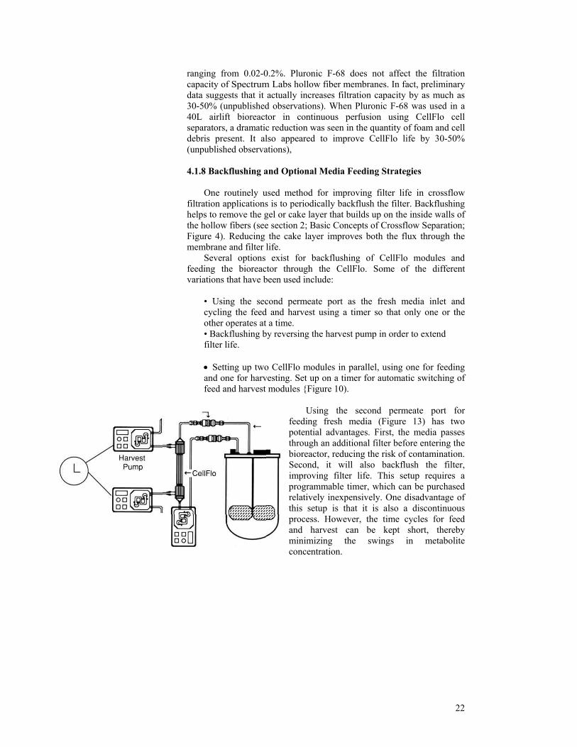
• Using the second permeate port as the fresh media inlet and cycling the feed and harvest using a timer so that only one or the other operates at a time. • Backflushing by reversing the harvest pump in order to extend filter life. • Setting up two CellFlo modules in parallel, using one for feeding and one for harvesting. Set up on a timer for automatic switching of feed and harvest modules {Figure 10).
22
olite concentration.
Using the second permeate port for feeding fresh media (Figure 13) has two potential advantages. First, the media passes through an additional filter before entering the bioreactor, reducing the risk of contamination. Second, it will also backflush the filter, improving filter life. This setup requires a programmable timer, which can be purchased relatively inexpensively. One disadvantage of this setup is that it is also a discontinuous process. However, the time cycles for feed and harvest can be kept short, thereby minimizing the swings in metab
23
occasional cy
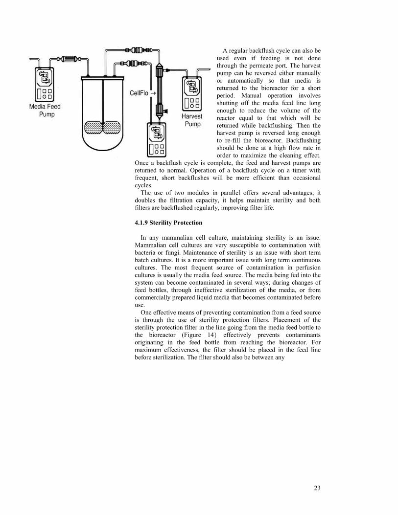
erility and both filters are backflushed regularly, improving filter life.
4. 9 Sterility Protection
ercially prepared liquid media that becomes contaminated before us
he feed line before sterilization. The filter should also be between any
A regular backflush cycle can also be used even if feeding is not done through the permeate port. The harvest pump can he reversed either manually or automatically so that media is returned to the bioreactor for a short period. Manual operation involves shutting off the media feed line long enough to reduce the volume of the reactor equal to that which will be returned while backflushing. Then the harvest pump is reversed long enough to re-fill the bioreactor. Backflushing should be done at a high flow rate in order to maximize the cleaning effect.
Once a backflush cycle is complete, the feed and harvest pumps are returned to normal. Operation of a backflush cycle on a timer with frequent, short backflushes will be more efficient than
cles. The use of two modules in parallel offers several advantages; it
doubles the filtration capacity, it helps maintain st
1. In any mammalian cell culture, maintaining sterility is an issue.
Mammalian cell cultures are very susceptible to contamination with bacteria or fungi. Maintenance of sterility is an issue with short term batch cultures. It is a more important issue with long term continuous cultures. The most frequent source of contamination in perfusion cultures is usually the media feed source. The media being fed into the system can become contaminated in several ways; during changes of feed bottles, through ineffective sterilization of the media, or from comm
e. One effective means of preventing contamination from a feed source
is through the use of sterility protection filters. Placement of the sterility protection filter in the line going from the media feed bottle to the bioreactor (Figure 14} effectively prevents contaminants originating in the feed bottle from reaching the bioreactor. For maximum effectiveness, the filter should be placed in t

24
, ensures that all connections are made "ups
ter in parallel. When one filter becomes clogged, another can be used.
n and 5.1 Sterilization Sanitization
diation, or ethylene oxide. They may be sanitized by chemical flushing.
5.1. oclaving a Perfusion Loop Containing a CellFlo Module
for loop
n or bubble point tested, refer to
of the loop, making sure to leave any valves or
ure cycle above 124°C as damage to the CellFlo module may occur.
connection point and the bioreactor. For example, if the perfusion run lasts longer than the media from a single container, the media containers will need to be switched, which requires aseptic connections. All such connections should be made "upstream" of the filter. If a contamination occurs in the media feed, it will be stopped by the sterility protection filter. However, once detected, both the media container and the filter must be removed and replaced. Without a second filter, replacement requires an unprotected aseptic connection. However, the dual filter arrangement shown in Figure 15
tream" of a sterilizing filter. Sterility protection filters work best with serum free media only. The
presence of serum in media reduces the filtration capacity of the filters. This reduction with serum may shorten the filter life below the life expectancy of the culture. In cases where the filter life is less than desired, the filter may be changed aseptically or the original system may be configured with more than one fil
5. Sterilizatio
CellFlo modules can be sterilized by autoclaving, ra
1 Aut 1. Pre-wet the CellFlo module with clean water. 2. Assemble a complete perfusion loop including all tubing, connectors and the CellFlo module (see section 3configuration). Do not fully tighten the sanitary clamps. Note: If the module is to be diffusiosection 6.1 for wetting procedure. 3. Wrap the endsconnectors open. 4. Autoclave the complete perfusion loop at 121°C for 30 minutes on a slow exhaust cycle. Note: Do not use a temperat
25
5. Allow the system to cool to room temperature and finger-tighten all clamps to assure a proper seal. 6. Check that all tubing connections are tight and close any valves or
connectors on the ends of the loop. Note: Spectrum Labs warrants CellFlo Modules to be auioclavable one time. Due to the potential variability of use and storage beyond our control no warranty is given, nor implied, for repeated, autoclavability.
5.1.2 Chemical Sanitization
If you wish to sanitize the entire perfusion loop including the CellFlo module in place, it may be chemically sanitized by flushing one of the following solutions through the assembled loop under the following conditions:
1. Sodium Hypochlorite - 200 ppm for 20 minutes. 2. Formaldehyde - 0.5% for 20 minutes. 3. Hydrogen Peroxide - 2.0% for 20 minutes. 4. Hot Water - 180°F (82°C) for 1-2 hours.
6. Integrity Testing Integrity testing may be performed by several methods: • Pressure Hold Test • Diffusion Test • Bubble Point Test If your validation scheme requires diffusion or bubble point
testing of the module, temporary modifications will be necessary to the perfusion loop.
Prior to initial integrity testing, dry modules must be primed to ensure complete fiber wetting. Priming and integrity testing of modules requires modification of the basic perfusion loop setup. To modify the setup, a "Tee" connector is inserted in the perfusion loop at the inlet and outlet ends of the CellFlo as shown in Figure 16. A length of tubing is connected to each Tee. Clamps to restrict the tubing arc required as shown in Figure 16.
6.1 Wetting the CellFlo Module (Figure 16) Wetting of a Cellflo module that has already been assembled ir\t» a perfusion loop and sterilized is difficult. If an integrity test is required, the CellFlo module should be wetted before sterilization.
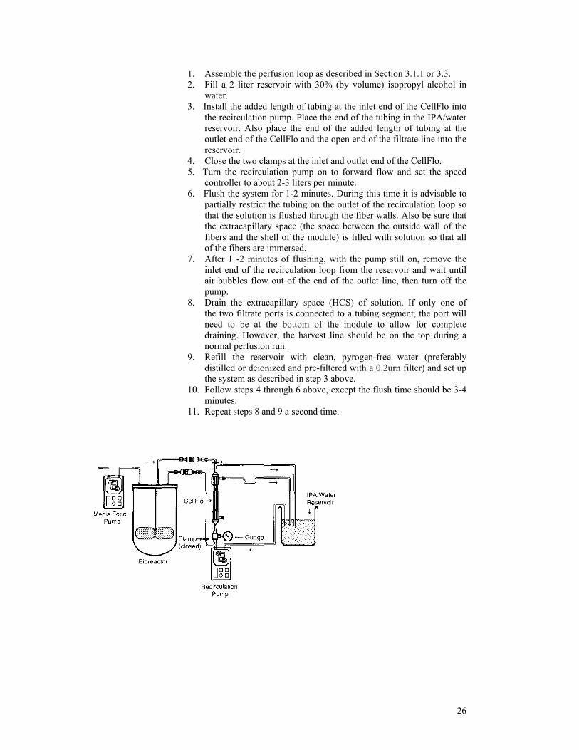
1. Assemble the perfusion loop as described in Section 3.1.1 or 3.3. 2. Fill a 2 liter reservoir with 30% (by volume) isopropyl alcohol in
water. 3. Install the added length of tubing at the inlet end of the CellFlo into
the recirculation pump. Place the end of the tubing in the IPA/water reservoir. Also place the end of the added length of tubing at the outlet end of the CellFlo and the open end of the filtrate line into the reservoir.
4. Close the two clamps at the inlet and outlet end of the CellFlo. 5. Turn the recirculation pump on to forward flow and set the speed
controller to about 2-3 liters per minute. 6. Flush the system for 1-2 minutes. During this time it is advisable to
partially restrict the tubing on the outlet of the recirculation loop so that the solution is flushed through the fiber walls. Also be sure that the extracapillary space (the space between the outside wall of the fibers and the shell of the module) is filled with solution so that all of the fibers are immersed.
7. After 1 -2 minutes of flushing, with the pump still on, remove the inlet end of the recirculation loop from the reservoir and wait until air bubbles flow out of the end of the outlet line, then turn off the pump.
8. Drain the extracapillary space (HCS) of solution. If only one of the two filtrate ports is connected to a tubing segment, the port will need to be at the bottom of the module to allow for complete draining. However, the harvest line should be on the top during a normal perfusion run.
9. Refill the reservoir with clean, pyrogen-free water (preferably distilled or deionized and pre-filtered with a 0.2urn filter) and set up the system as described in step 3 above.
10. Follow steps 4 through 6 above, except the flush time should be 3-4 minutes.
11. Repeat steps 8 and 9 a second time.
26
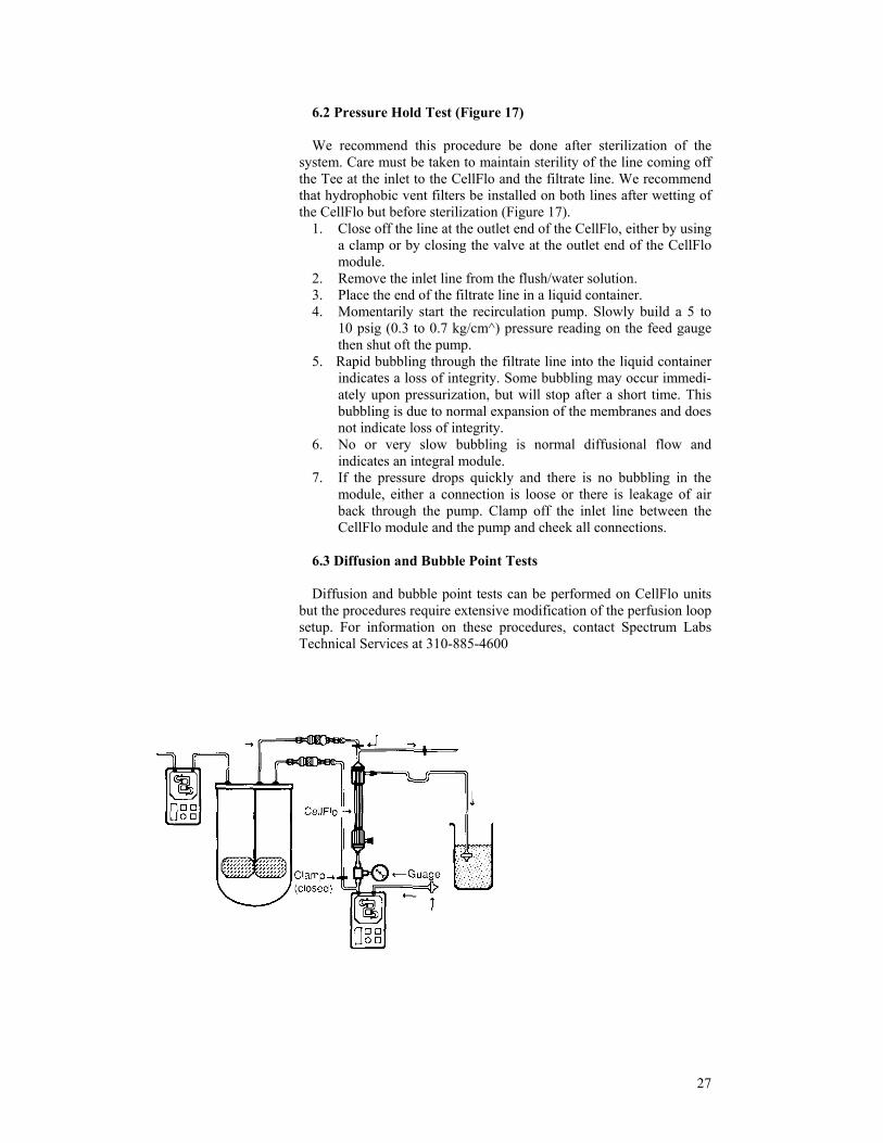
6.2 Pressure Hold Test (Figure 17) We recommend this procedure be done after sterilization of the
system. Care must be taken to maintain sterility of the line coming off the Tee at the inlet to the CellFlo and the filtrate line. We recommend that hydrophobic vent filters be installed on both lines after wetting of the CellFlo but before sterilization (Figure 17).
1. Close off the line at the outlet end of the CellFlo, either by using a clamp or by closing the valve at the outlet end of the CellFlo module.
2. Remove the inlet line from the flush/water solution. 3. Place the end of the filtrate line in a liquid container. 4. Momentarily start the recirculation pump. Slowly build a 5 to
10 psig (0.3 to 0.7 kg/cm^) pressure reading on the feed gauge then shut oft the pump.
5. Rapid bubbling through the filtrate line into the liquid container indicates a loss of integrity. Some bubbling may occur immedi-ately upon pressurization, but will stop after a short time. This bubbling is due to normal expansion of the membranes and does not indicate loss of integrity.
6. No or very slow bubbling is normal diffusional flow and indicates an integral module.
7. If the pressure drops quickly and there is no bubbling in the module, either a connection is loose or there is leakage of air back through the pump. Clamp off the inlet line between the CellFlo module and the pump and cheek all connections.
6.3 Diffusion and Bubble Point Tests Diffusion and bubble point tests can be performed on CellFlo units
but the procedures require extensive modification of the perfusion loop setup. For information on these procedures, contact Spectrum Labs Technical Services at 310-885-4600
27
28
7. References
1. Ratafia, M. 1987. Mammalian cell culture: worldwide activities and markets. Biotechnology 6(7); 692-694.
2. Griffiths, J.B. 1988. Overview of cell culture systems and their scale-up, In: Animal Cell Biotechnology, Vol. III, chapter 8. Spire, R.E. and Griffiths, J.B. (Eds.) Academic Press, London.
3. Van Brunt, J. 1987. A closer look at fermenters and bioreactors. Biotechnology 5(11); 1134-1138.
4. Knight, P. 1988. Fermentation special report. Biotechnology 6(5); 506-516. 5. Glacken, M.W. 1988. Catabolic control of mammalian cell culture. Biotechnology 5(11); 1134-
1138. 6. Parkinson, G. 1988. The next wave of bioprocessing arrives. Chem. Eng. 95(18); 37-44. 7. Tolbert, W.R., Srigley, W.R. and Prior, C.P. 1988. Perfusion culture systems for large scale
pharmaceutical production. In: Animal Cell Biotechnology, Spire, R.E. and Griffiths, J.B. (Eds.) Vol. III, Chapter 17, Academic Press, London.
8. Murphy, T.J. 1988. Continuous perfusion in a 40L airlift bioreactor. Microgon Technical Report.
9. Prior, C.P., Prior, G.M. and Hope, J.A. 1989. Perfusion technology; a production method for human rtPA. Amer. Biotech. Lab. 6(3); 25-31.
10. MacMichael, G.J. 1989. The use of perfusion in mammalian cell culture. Amer. Biotech. Lab. 6(3); 34-42.
11. Prior, C.P., Doyle, K.R., Duffy, S.A., Hope, J.A., Moellering, B.J., Prior, G.M., Scott, R.W. and Tolbert, W.R. 1989. The recovery of highly purified biopharmaceuticals from perfusion cell culture bioreactors. J. Parent. Sci. and Technol., 43(1); 15-23.
12. Tutunjian, R.S. 1984. Cell separations with hollow fiber membranes. Developments in Industrial Microbiology 25: 415-4356.
13. Glacken, M.W., Fleishaker, R.J. and Sinskey, A.J. 1986. Reduction of waste product excretion via nutrient control: possible strategies for maximizing product and cell yields on serum in cultures of mammalian cells. Biotech. And Bioeng. 28; 1376-1389.
14. Miller, W.M., Blanch, H.W. and Wilke, C.R. 1988. A kinetic analysis of hybridoma growth and metabolism in batch and continuous suspension culture: effect of nutrient concentration, dilution rate and pH. Biotech. And Bioeng. 32; 947-965.
15. Glacken, M.W., Adema, E. and Sinskey, A.J. 1988. Mathematical descriptions of hybridoma culture kinetics: I. Intial metabolic rates. Biotech. And Bioeng. 32; 491-506.
16. Reuveny, S., Velez, D., Macmillan, J.D. and Miller, L. 1986. Factors affecting cell growth and monoclonal antibody production in stirred reactors. J. Immunol. Methods 86; 53-60
17. Thorpe, J.S., Murdin, A.D., Sanders, P.G. and Spier, R.E. 1987. The effect of waste products of cellular metabolism on growth and protein synthesis in a mouse hybridoma cell line. Paper presented at the 194th ACS National Meeting, New Orleans.
18. Miller, W.M., Wilke, C.R. and Blanch, H.W. 1989. Transient responses of hybridoma cells to nutrient additions in continuous culture: I. Glucose pulse and step changes. Biotech and Bioeng. 33; 477-486.
19. Miller, W.M., Wilke, C.R. and Blanch, H.W. 1989. Transient responses of hybridoma cells to nutrient additions in continuous culture: II. Glucose pulse and step changes. Biotech and Bioeng. 33; 487-499.
20. Maiorella, B., Dorin, Glenn, Harano, D., Carion, A. and Keutzer, B. 1988. Design considerations for aseptic crossflow microfiltration harvesting of viable animal cells. Paper presented at the AICHE National Meeting, Washington, D.C.
21. Cheryan, M. 1986. Ultrafiltration Handbook, pg 112. Technomic Publishing, Lancaster, PA. 22. Bird, R.B., Stewart, W.E. and Lightfoot, E.N. 1960. Transport Phenomena, pg 46. John Wiley
and Sons, New York. 23. Bliem, R. and Katinger, H. 1988. Scale-up engineering in animal cell technology: Part II.
TIBTECH 6(9); 224-230. 24. Lauffenburger, D. and Cozens, C. 1989. Regulation of mammalian cell growth by autocrine
growth factors: Analysis of consequences for inoculum cell density effect. Biotech and Bioeng. 33; 1365-1378.
25. Murhammer, D.W. and Goochee, C.F. 1988. Scaleup of insect cell cultures: protective effects

29
of Pluronic F-68. Biotechnology 6(12); 1411-1418. 26. Handa, A., Emery, A.N. and Spier, R.E. 1987. On the evaluation of gas-liquid interfacial effects
on hybridoma viability in bubble column bioreactors. Develop. Biol. Standard. 66; 241-252. 27. Handa, A., Emery, A.N. and Spier, R.E. 1987. Effect of gas-liquid inter faces on the growth of
mammalian cells: mechanisms of cell damage by bubbles. Presented at the 8th meeting of Eur. Soc. for Animal Cell Technology, Israel.