Embed Size (px)
Citation preview
1045-9219 (c) 2013 IEEE. Personal use is permitted, but republication/redistribution requires IEEE permission. Seehttp://www.ieee.org/publications_standards/publications/rights/index.html for more information.
This article has been accepted for publication in a future issue of this journal, but has not been fully edited. Content may change prior to final publication. Citationinformation: DOI 10.1109/TPDS.2014.2310471, IEEE Transactions on Parallel and Distributed Systems
1
Cooperative Positioning and Tracking inDisruption Tolerant Networks
Wenzhong Li, Member, IEEE, Yuefei Hu, Student Member, IEEE, Xiaoming Fu, SeniorMember, IEEE, Sanglu Lu, Member, IEEE, and Daoxu Chen, Member, IEEE
Abstract—With the increasing number of location-dependent applications, positioning and tracking a mobile device becomesmore and more important to enable pervasive and context-aware service. While extensive research has been performed inphysical localization and logical localization for satellite, GSM and WiFi communication networks where fixed reference pointsare densely-deployed, positioning and tracking techniques in a sparse disruption tolerant network (DTN) have not been welladdressed. In this paper, we propose a decentralized cooperative method called PulseCounting for DTN localization and aprobabilistic tracking method called ProbTracking to confront this challenge. PulseCounting evaluates the user walking stepsand movement orientations using accelerometer and electronic compass equipped in cellphones. It estimates user location byaccumulating the walking segments, and improves the estimation accuracy by exploiting the encounters of mobile nodes. Severalmethods to refine the location estimation are discussed, which include the adjustment of trajectory based on reference pointsand the mutual refinement of location estimation for encountering nodes based on maximum-likelihood. To track user movement,the proposed ProbTracking method uses Markov chain to describe movement patterns and determines the most possible userwalking trajectories without full record of user locations. We implemented the positioning and tracking system in Android phonesand deployed a testbed in the campus of Nanjing University. Extensive experiments are conducted to evaluate the effectivenessand accuracy of the proposed methods, which show an average deviation of 9m in our system compared to GPS.
Index Terms—Disruption tolerant network, positioning, tracking, cooperation
F
1 INTRODUCTION
Disruption tolerant networks (DTNs) are sparse mo-bile ad hoc networks where nodes connect with eachother intermittently [1]. Since DTNs allow peopleto communicate without network infrastructure, theyare widely used in battlefields, wildlife tracking, andvehicular communications [2]. Location informationis extremely important to enable context-aware andlocation-based applications [3]. However, due to thelack of fixed infrastructure and continuous networkconnection in DTNs, identifying the location of mobileusers and tracking their movement trajectories arechallenging.
The following scenario illustrates the localizationproblems in DTNs. Assume a DTN is formed by aset of wireless nodes (e.g., cellphones) moving withina field. Each node has a communication range ofdistance r (r > 0). Two nodes can communicatewhen they move into each other’s communicationrange, which is called an encounter of nodes. SinceDTNs are sparse and highly dynamic, a constantcommunication path does not exist between any pairof nodes. As illustrated in Fig. 1, there are fourdifferent components in the system. The landmarks
• W. Li, Y. Hu, S. Lu, and D. Chen are with the State Key Laboratory forNovel Software Technology, Nanjing University, Xianlin Street 163,Nanjing 210023, China. E-mail: [email protected]
• X. Fu is with the Institute of Computer Science, University ofGoettingen, Goldschmidtstr. 7, Goettingen 37077, Germany.E-mail: [email protected]
����������
�����������
� ����������
�����������
� ����������
�����������
���� � ��������� �
��� ����
Fig. 1. The components of a DTN localization system.
represent fix-deployed infrastructures like WiFi accesspoints (APs), which can provide network service. Aninfostation is a server connecting to the APs to collectinformation from mobile nodes. The GPS-nodes arehigh-end mobile devices equipped with Global Po-sitioning System (GPS). There are only a few of themin the network and they can be used as mobile ref-erence points. The common-nodes are ordinary mobilephones without GPS support, which have the majoritynumber in the system. They are only equipped withsimple sensors (such as accelerometer and electroniccompass), and can communicate with other nodes viaWiFi or Bluetooth occasionally.
The positioning and tracking problem in DTNs istwofold: the common-nodes (without GPS module)need to determine their locations based on the limitednumber of reference points (APs or GPS nodes) theyencountered; and the infostation needs to track thetrajectories of the common-nodes with the partialinformation collected by the APs opportunistically.
1045-9219 (c) 2013 IEEE. Personal use is permitted, but republication/redistribution requires IEEE permission. Seehttp://www.ieee.org/publications_standards/publications/rights/index.html for more information.
This article has been accepted for publication in a future issue of this journal, but has not been fully edited. Content may change prior to final publication. Citationinformation: DOI 10.1109/TPDS.2014.2310471, IEEE Transactions on Parallel and Distributed Systems
2
Early positioning systems rely on triangulation us-ing physical signals from the fixed-deployed infras-tructures such as GPS satellites [4], [5] and GSMcelltowers [6], [7]. WiFi-based localization strategiescollect the radio fingerprints quantified from the WiFisignal strengths at many physical positions and mul-tiple APs, and identify user location by retrieving andmatching the fingerprints [8], [9]. Such methods eitherrequire densely-deployed infrastructures or they needto collect a large amount of signal samples, whichcannot be applied to sparse networks.
Several recent research focuses on GPS-free localiza-tion in wireless networks by incorporating fixed land-marks and surrounding characteristics. Surround-Sense [10] identifies logical location using the sur-rounding information like sounds, lights and colors.CompAcc [11] adopts a distance estimation methodusing accelerometer and compass and determines lo-cation by matching to possible path signatures gen-erated from an electronic map. Escort [12] provides alogical navigation system to help a person navigateto another person in a public place with the aidof context features. However, these methods needcontinuous communication with a centralized serverto process a large amount of surrounding data, whichare not suitable for the decentralized structure and theopportunistic communication nature of DTNs.
In this paper, we propose a decentralized cooper-ative method called PulseCounting for DTN localiza-tion and a probabilistic method called ProbTracking totrack the movement of mobile nodes. PulseCountingevaluates the number of user walking steps usingthe accelerometer data, and decides the orientation ofeach step using the electronic compass measurements.By accumulating the segments of walking steps, it isable to form an estimation of current location. PulseC-ounting further takes advantage of the opportunity ofencounters in DTNs to refine the location estimation:on the one hand, the encountering APs and phonesequipped with GPS could be regarded as referencepoints; on the other hand, the encounters of two mo-bile nodes enable the possibility of mutual adjustmentto reduce estimation error. ProbTracking detects themovement trajectory based on the partial locationinformation reported by the other mobile nodes. Itconstructs a Markov chain using the movement his-tory data and uses it to determine the most proba-ble user walking route without the need for globallocation information in DTNs. We implemented thepositioning and tracking system in Android phones,and deployed a testbed in the campus of NanjingUniversity for performance evaluation. Experimentsshow that the system has an average deviation of 9mcompared to GPS.
2 RELATED WORKDisruption tolerant networks (DTNs) have been wide-ly studied in the last decade. Most existing works
focus on the fundamental problem of data routing inDTNs. To achieve data transmission without the needof end-to-end communication paths, several mobility-assisted routing strategies have been proposed toreduce the number of hops, the delivery delay andenergy consumption [1], [2], [13], [14]. A few worksaddressed the issues of selfish behavior of nodes toenhance the cooperation for data relays in DTNs [15],[16]. Different from the existing works, this paperfocuses on the issues of positioning and trackingmobile nodes in DTNs, which have not been welladdressed in the past.
Previous research on wireless localization rely ondeploying wireless infrastructures (e.g. telecommuni-cation satellites or cell towers) and installing dedi-cated hardware (e.g. GPS modules or RFIDs) in theenvironment [17], [4]. In these systems, mobile devicesmeasure the wireless signals to several infrastructuresin known locations and estimate the actual locationsbased on their geometric relationships.
Cell tower triangulation is a popular technique fordetermining the location of a mobile device [6], [7].Locating the position of mobile phones by measuringsignals to GSM celltowers was studied in [7], whichshowes that GSM devices can achieve a positioningaccuracy with a median error of 94-196 meters.
WiFi-based strategies rely on deploying fixed Ac-cess Points (APs) and require calibrating WiFi signalstrengths at many physical positions to enable local-ization. RADAR [8] constructs detailed radio finger-prints of the available APs and combines empiricalmeasurements with signal propagation modeling todetermine user location . Place Lab [9] allows com-modity hardware clients like PDAs and cell phonesto locate themselves by listening for radio beaconsof WiFi and GSM cell towers. It generates a radiomap by war-driving and estimates the location of mo-bile devices by looking up the overhead WiFi/GSMbeacons in the radio map. Several indoor localizationapproaches using WiFi signals was discussed in [18],[19], [20].
In the recent years, a couple of works addressthe issues of localization using fixed landmarks andsurroundings. SurroundSense [10] identifies a user’slocation using the surrounding information collectedby sensors and camera on mobile phones. The mainidea is to fingerprint the location based on its ambientsound, light, color, RF, as well as the layout-induceduser movement. However, it can only obtain a user’slogical location like in Starbucks or McDonalds, butfails to provide the geographical coordinates. AAMPL[21] introduces a location estimation method usingaccelerometer and compass. It can estimate roughphysical coordinates of mobile phones augmentingwith context-aware logical localization. To improvelocation accuracy, CompAcc [11] uses the similar es-timation method like AAMPL, and refines the loca-tion estimation by matching it against possible path
1045-9219 (c) 2013 IEEE. Personal use is permitted, but republication/redistribution requires IEEE permission. Seehttp://www.ieee.org/publications_standards/publications/rights/index.html for more information.
This article has been accepted for publication in a future issue of this journal, but has not been fully edited. Content may change prior to final publication. Citationinformation: DOI 10.1109/TPDS.2014.2310471, IEEE Transactions on Parallel and Distributed Systems
3
signatures generated from a local map. It achieves alocation accuracy of less than 11 meters. However,it needs to construct path signatures from electron-ic maps beforehand, which is complex and time-consuming. Escort [12] provides a logical navigationsystem for social localization. Its goal is not to identifythe physical location, but to help a person navigateto another person in a public place such as a hotel.By periodically learning the walking trails of differentindividuals, as well as how they encounter each otherin space-time, a route is computed between any pairof persons. However, it needs global information ofusers’ movements and their encounters to constructthe navigation graph, which does not apply for DTNs.
3 COOPERATIVE POSITIONING IN DTNS
In DTNs, most of time the common-nodes have noGPS-nodes and landmarks within their communica-tion range, which makes them hard to decide theirlocations. We propose the PulseCounting method forCooperative Positioning in DTNs, which consists thefollowing six steps.
3.1 BootstrappingAs the first step, each node needs to know its po-sition initially. Without the initial position, there isno reference point for location estimation. In DTNs,we assume a small number of fixed landmarks (e.g.,wireless APs) are deployed in the environment withknown locations. We also assume that there are a fewGPS-nodes willing to report their locations to othernodes. Thus the common-nodes can obtain a roughinitial location when they firstly encounter the land-marks or GPS-nodes. It is unlikely for all common-nodes to obtain their initial locations at the same time,so the initialization process is asynchronous.
With the initial location information, a map in thisarea will be downloaded to the user’s cellphone.We use the Google Map [22] in our implementationsince it provides open access to its data and APIs.The map is downloaded opportunistically when thedevice has a chance to access the Internet (i.e., enter-ing the communication range of an AP). Unlike theexisting positioning systems such as AAMPL [21] andCompAcc [11], the proposed PulseCounting methoddoes not rely on the Map data to aid localization.It purposes just to help visualizing the movementtrajectory on the cellphone screen.
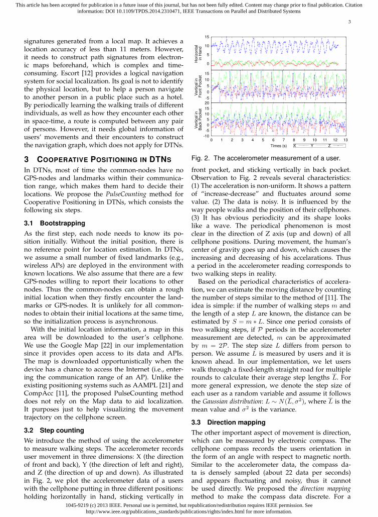
3.2 Step countingWe introduce the method of using the accelerometerto measure walking steps. The accelerometer recordsuser movement in three dimensions: X (the directionof front and back), Y (the direction of left and right),and Z (the direction of up and down). As illustratedin Fig. 2, we plot the accelerometer data of a userswith the cellphone putting in three different positions:holding horizontally in hand, sticking vertically in
0
5
10
15
Ho
rizo
nta
l in
Ha
nd
-5
0
5
10
15
Ve
rtic
al in
F
ron
t P
ocke
t
-10
-5
0
5
10
15
20
0 1 2 3 4 5 6 7 8 9 10 11 12 13
Ve
rtic
al in
B
ack P
ocke
t
Times (s) X Y Z
Fig. 2. The accelerometer measurement of a user.
front pocket, and sticking vertically in back pocket.Observation to Fig. 2 reveals several characteristics:(1) The acceleration is non-uniform. It shows a patternof “increase-decrease” and fluctuates around somevalue. (2) The data is noisy. It is influenced by theway people walks and the position of their cellphones.(3) It has obvious periodicity and its shape lookslike a wave. The periodical phenomenon is mostclear in the direction of Z axis (up and down) of allcellphone positions. During movement, the human’scenter of gravity goes up and down, which causes theincreasing and decreasing of his accelarations. Thusa period in the accelerometer reading corresponds totwo walking steps in reality.
Based on the periodical characteristics of accelera-tion, we can estimate the moving distance by countingthe number of steps similar to the method of [11]. Theidea is simple: if the number of walking steps m andthe length of a step L are known, the distance can beestimated by S = m ∗ L. Since one period consists oftwo walking steps, if P periods in the accelerometermeasurement are detected, m can be approximatedby m = 2P . The step size L differs from person toperson. We assume L is measured by users and it isknown ahead. In our implementation, we let userswalk through a fixed-length straight road for multiplerounds to calculate their average step lengths L. Formore general expression, we denote the step size ofeach user as a random variable and assume it followsthe Gaussian distribution: L ∼ N(L, σ2), where L is themean value and σ2 is the variance.
3.3 Direction mappingThe other important aspect of movement is direction,which can be measured by electronic compass. Thecellphone compass records the users orientation inthe form of an angle with respect to magnetic north.Similar to the accelerometer data, the compass da-ta is densely sampled (about 22 data per seconds)and appears fluctuating and noisy, thus it cannotbe used directly. We proposed the direction mappingmethod to make the compass data discrete. For a
1045-9219 (c) 2013 IEEE. Personal use is permitted, but republication/redistribution requires IEEE permission. Seehttp://www.ieee.org/publications_standards/publications/rights/index.html for more information.
This article has been accepted for publication in a future issue of this journal, but has not been fully edited. Content may change prior to final publication. Citationinformation: DOI 10.1109/TPDS.2014.2310471, IEEE Transactions on Parallel and Distributed Systems
4
rough estimation, we project the compass data to eightdiscrete directions: North, Northeast, East, Southeast,South, Southwest, West, and Northwest, which arenumbered by 0−7 accordingly. Assume Υ is a readingof the compass taking the value from [0, 360], wecalculate its direction mapping by
(argmink |Υ− 360
8k|) mod 8. (1)
With Eq. (1), a compass reading is mapped to adirection with the angle within the departure from−22.5◦ to +22.5◦. For example, the value Υ = 340◦
will be mapped to 0, which represents the direction“North”; Υ = 100◦ will be mapped to 2, whichrepresents the direction “East”.
To reduce the noise and fluctuation of compassmeasurement, we use the latest K compass readingsto decide the movement direction. After mapping allthe K readings, if a direction has the majority number,it will be taken as the movement direction. K is setto 22 in our system.
Mapping to eight discrete directions is a rough esti-mation. It implies that the system can tolerate at most±22.5◦ of deviation in the movement direction. Onecan easily extend it to more fine-grained expressionsuch as 16 or 32 directions.
3.4 Trajectory generation
With the results from step counting and directionmapping, we are able to describe user movementtrajectories. A movement trajectory is defined as aseries of segments with distance and direction:
T (P0 → P1) = {< S1, θ1 >, · · · , < SM , θM >}, (2)
where P0 is the departure point and P1 is the desti-nation point of the trajectory. Each tuple < Si, θi >(i = 1, 2, · · · ,M) indicates a segment of the move-ment. Si is the moving distance of two consecutivewalking steps (one period of the acceleration); θi isthe movement direction (measured by the angle to thenorth) in the steps, which is obtained by the directionmapping method. M is the total number of segments.
3.5 Location estimation
Given a trajectory T (P0 → P1), if the location ofdeparture point P0 is known, we can roughly estimatethe location of P1 by accumulating the trajectorysegments. Assume the coordinate of P0 is (x0, y0). Ac-cording to the segments, the user moves horizontallyin the total displacement
∑Mi=1 Si sin θi, and moves
vertically in the total displacement∑M
i=1 Si cos θi. Sothe location coordinate of P1 is approximated by
(x0 +M∑i=1
Si sin θi, y0 +M∑i=1
Si cos θi). (3)
Theoretically, if the initial location of a node isknown, we can estimate its location at any time with
P0
P'1
P1
<S1, 1><S2, 2>
<S3, 3>
<S4, 4>
<S'1, 1><S'2, 2>
<S'3, 3>
<S'4, 4>
rbefore adjustment
after adjustment
P1: estimate location
P'1: reference point
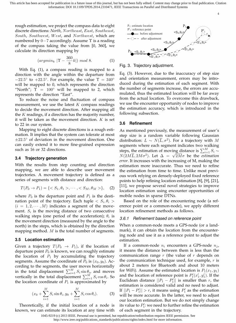
Fig. 3. Trajectory adjustment.
Eq. (3). However, due to the inaccuracy of step sizeand orientation measurement, errors may be intro-duced during the estimation of each segment. Withthe number of segments increase, the errors are accu-mulated, thus the estimated location will be far awayfrom the actual location. To overcome this drawback,we use the encounter opportunity of nodes to improvethe estimation accuracy, which is introduced in thefollowing subsection.
3.6 Refinement
As mentioned previously, the measurement of user’sstep size is a random variable following Gaussiandistribution: L ∼ N(L, σ2). For a trajectory with Msegments where each segment indicates two walkingsteps, the estimation of moving distance is
∑Mi=1 Si ∼
N(2ML, 2Mσ2). Let ∆ =√2Mσ be the estimation
error. It increases with the increasing of M, making theestimation more inaccurate. Thus we need to refinethe estimation from time to time. Unlike most previ-ous work relying on densely-deployed fixed referencepoints to help refining location estimation [8], [9], [21],[11], we propose several novel strategies to improvelocation estimation using encounter opportunities ofmobile nodes in sparse DTNs.
Based on the role of the encountering node (a ref-erence point or a common-node), we apply differentlocation refinement methods as follows.
3.6.1 Refinement based on reference point
When a common-node meets a GPS-node (or a land-mark), it can obtain the location from the encounter-ing node and use it as a reference point to adjust theestimation.
If a common-node ni encounters a GPS-node nj ,it means the distance between them is less than thecommunication range r (the value of r depends onthe communication technique used, for example, r isabout 2 meters for Bluetooth and about 10 metersfor WiFi). Assume the estimated location is P1(x1, y1)and the location of reference point is P ′
1(x′1, y
′1). If the
Euclidean distance ||P1 − P ′1|| is smaller than r, the
estimation is considered valid and no need to adjust.If ||P1 − P ′
1|| > r, it means using P ′1 as the estimation
will be more accurate. In the latter, we need to adjustour location estimation. But we do not simply changeits value to P ′
1: we need to further refine the estimationof each segment in the trajectory.
1045-9219 (c) 2013 IEEE. Personal use is permitted, but republication/redistribution requires IEEE permission. Seehttp://www.ieee.org/publications_standards/publications/rights/index.html for more information.
This article has been accepted for publication in a future issue of this journal, but has not been fully edited. Content may change prior to final publication. Citationinformation: DOI 10.1109/TPDS.2014.2310471, IEEE Transactions on Parallel and Distributed Systems
5
The basic idea to refine the segments is to amortizethe errors. For simplicity we only adjust the lengthof each segment and leave the approximate angleunchanged. An example of trajectory adjustment isshown in Fig. 3. Assume the trajectory after adjust-ment is:
T ′(P0 → P ′1) = {< S′
1, θ1 >, · · · < S′M , θM >}. (4)
According to Eq. (3), the coordinates of P ′1(x
′1, y
′1) sat-
isfy: x0+∑M
i=1 S′i sin θi = x′
1, and y0+∑M
i=1 S′i cos θi =
y′1. However, there are numerous solutions in accor-dance with the above equations, which infer differentwalking trajectories. We are interested in finding theshortest path from P0 to P ′
1, hoping that the step sizeafter adjustment is not far away from its previousestimation, i.e. within a predefined threshold ε.
In summary, the trajectory adjustment problem canbe expressed as:
minimize∑M
i=0 S′i, (5)
s.t. ∑Mi=1 S
′i sin θi = x′
1 − x0,∑Mi=1 S
′i cos θi = y′1 − y0,
S′i > 0, i = 1, · · · ,M,
||S′i − Si|| ≤ ε, i = 1, · · · ,M.
This problem is an optimization problem and it canbe solved by using Linear programming [23]. Solvingthis problem, we can adjust Si to S′
i (i = 1, · · · ,M ).After adjustment, the estimation error becomes ∆ ≤ r,which is more accurate than the previous estimation.
The novelty of the trajectory adjustment methodis that it is decentralized and transitive. Whenever acommon-node encounters a GPS-node or a landmark,it can adjust its location estimation locally. The morefrequent the encounter occurs, the more accuracy thelocation estimation achieves. Furthermore, by solvingthe optimization problem, the proposed adjustmentmethod can not only refine the current location, butalso trace back to refine previous segments, whichcan amortize the estimation error and obtain a moreaccurate trajectory.
3.6.2 Mutual refinementWhen a common-node encounters another common-node, although both of them have no accurate locationinformation, it is still possible for them to use eachother as reference point to refine location estimation.Assume ni and nj are the two common-nodes, wediscuss the following situations of encountering.
a) ni and nj encounter in a straight road.When two nodes ni and nj encounter in a straight
road, they will exchange their location estimation,which could be used as reference points to refine theirestimation. There are four different situations for therelative locations of the encountering nodes (refer to
�� ��
� � �� ��
��
� �
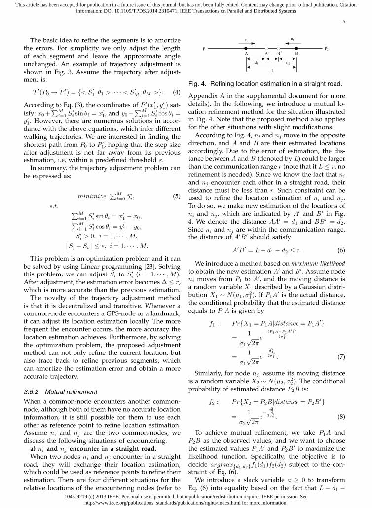
Fig. 4. Refining location estimation in a straight road.
Appendix A in the supplemental document for moredetails). In the following, we introduce a mutual lo-cation refinement method for the situation illustratedin Fig. 4. Note that the proposed method also appliesfor the other situations with slight modifications.
According to Fig. 4, ni and nj move in the oppositedirection, and A and B are their estimated locationsaccordingly. Due to the error of estimation, the dis-tance between A and B (denoted by L) could be largerthan the communication range r (note that if L ≤ r, norefinement is needed). Since we know the fact that ni
and nj encounter each other in a straight road, theirdistance must be less than r. Such constraint can beused to refine the location estimation of ni and nj .To do so, we make new estimation of the locations ofni and nj , which are indicated by A′ and B′ in Fig.4. We denote the distance AA′ = d1 and BB′ = d2.Since ni and nj are within the communication range,the distance of A′B′ should satisfy
A′B′ = L− d1 − d2 ≤ r. (6)
We introduce a method based on maximum-likelihoodto obtain the new estimation A′ and B′. Assume nodeni moves from P1 to A′, and the moving distance isa random variable X1 described by a Gaussian distri-bution X1 ∼ N(µ1, σ
21). If P1A
′ is the actual distance,the conditional probability that the estimated distanceequals to P1A is given by
f1 : Pr{X1 = P1A|distance = P1A′}
=1
σ1
√2π
e− (P1A−P1A′)2
2σ21
=1
σ1
√2π
e− d21
2σ21 . (7)
Similarly, for node nj , assume its moving distanceis a random variable X2 ∼ N(µ2, σ
22). The conditional
probability of estimated distance P2B is:
f2 : Pr{X2 = P2B|distance = P2B′}
=1
σ2
√2π
e− d22
2σ22 . (8)
To achieve mutual refinement, we take P1A andP2B as the observed values, and we want to choosethe estimated values P1A
′ and P2B′ to maximize the
likelihood function. Specifically, the objective is todecide argmax{d1,d2}f1(d1)f2(d2) subject to the con-straint of Eq. (6).
We introduce a slack variable a ≥ 0 to transformEq. (6) into equality based on the fact that L − d1 −
1045-9219 (c) 2013 IEEE. Personal use is permitted, but republication/redistribution requires IEEE permission. Seehttp://www.ieee.org/publications_standards/publications/rights/index.html for more information.
This article has been accepted for publication in a future issue of this journal, but has not been fully edited. Content may change prior to final publication. Citationinformation: DOI 10.1109/TPDS.2014.2310471, IEEE Transactions on Parallel and Distributed Systems
6
��
��
�
�
��
��
��
��
�
��
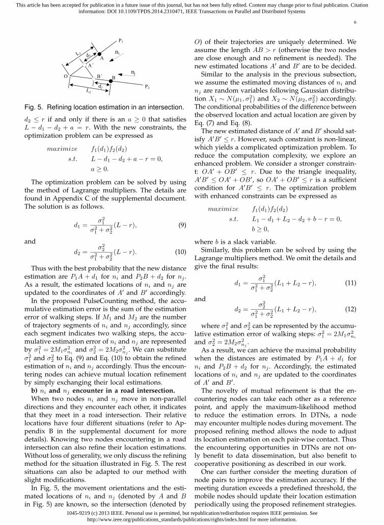
Fig. 5. Refining location estimation in an intersection.
d2 ≤ r if and only if there is an a ≥ 0 that satisfiesL − d1 − d2 + a = r. With the new constraints, theoptimization problem can be expressed as
maximize f1(d1)f2(d2)
s.t. L− d1 − d2 + a− r = 0,
a ≥ 0.
The optimization problem can be solved by usingthe method of Lagrange multipliers. The details arefound in Appendix C of the supplemental document.The solution is as follows.
d1 =σ21
σ21 + σ2
2
(L− r), (9)
and
d2 =σ22
σ21 + σ2
2
(L− r). (10)
Thus with the best probability that the new distanceestimation are P1A + d1 for ni and P2B + d2 for nj .As a result, the estimated locations of ni and nj areupdated to the coordinates of A′ and B′ accordingly.
In the proposed PulseCounting method, the accu-mulative estimation error is the sum of the estimationerror of walking steps. If M1 and M2 are the numberof trajectory segments of ni and nj accordingly, sinceeach segment indicates two walking steps, the accu-mulative estimation error of ni and nj are representedby σ2
1 = 2M1σ2ni
and σ22 = 2M2σ
2nj
. We can substituteσ21 and σ2
2 to Eq. (9) and Eq. (10) to obtain the refinedestimation of ni and nj accordingly. Thus the encoun-tering nodes can achieve mutual location refinementby simply exchanging their local estimations.
b) ni and nj encounter in a road intersection.When two nodes ni and nj move in non-parallel
directions and they encounter each other, it indicatesthat they meet in a road intersection. Their relativelocations have four different situations (refer to Ap-pendix B in the supplemental document for moredetails). Knowing two nodes encountering in a roadintersection can also refine their location estimations.Without loss of generality, we only discuss the refiningmethod for the situation illustrated in Fig. 5. The restsituations can also be adapted to our method withslight modifications.
In Fig. 5, the movement orientations and the esti-mated locations of ni and nj (denoted by A and Bin Fig. 5) are known, so the intersection (denoted by
O) of their trajectories are uniquely determined. Weassume the length AB > r (otherwise the two nodesare close enough and no refinement is needed). Thenew estimated locations A′ and B′ are to be decided.
Similar to the analysis in the previous subsection,we assume the estimated moving distances of ni andnj are random variables following Gaussian distribu-tion X1 ∼ N(µ1, σ
21) and X2 ∼ N(µ2, σ
22) accordingly.
The conditional probabilities of the difference betweenthe observed location and actual location are given byEq. (7) and Eq. (8).
The new estimated distance of A′ and B′ should sat-isfy A′B′ ≤ r. However, such constraint is non-linear,which yields a complicated optimization problem. Toreduce the computation complexity, we explore anenhanced problem. We consider a stronger constrain-t: OA′ + OB′ ≤ r. Due to the triangle inequality,A′B′ ≤ OA′ + OB′, so OA′ + OB′ ≤ r is a sufficientcondition for A′B′ ≤ r. The optimization problemwith enhanced constraints can be expressed as
maximize f1(d1)f2(d2)
s.t. L1 − d1 + L2 − d2 + b− r = 0,
b ≥ 0,
where b is a slack variable.Similarly, this problem can be solved by using the
Lagrange multipliers method. We omit the details andgive the final results:
d1 =σ21
σ21 + σ2
2
(L1 + L2 − r), (11)
andd2 =
σ22
σ21 + σ2
2
(L1 + L2 − r), (12)
where σ21 and σ2
2 can be represented by the accumu-lative estimation error of walking steps: σ2
1 = 2M1σ2ni
and σ22 = 2M2σ
2nj
.As a result, we can achieve the maximal probability
when the distances are estimated by P1A + d1 forni and P2B + d2 for nj . Accordingly, the estimatedlocations of ni and nj are updated to the coordinatesof A′ and B′.
The novelty of mutual refinement is that the en-countering nodes can take each other as a referencepoint, and apply the maximum-likelihood methodto reduce the estimation errors. In DTNs, a nodemay encounter multiple nodes during movement. Theproposed refining method allows the node to adjustits location estimation on each pair-wise contact. Thusthe encountering opportunities in DTNs are not on-ly benefit to data dissemination, but also benefit tocooperative positioning as described in our work.
One can further consider the meeting duration ofnode pairs to improve the estimation accuracy. If themeeting duration exceeds a predefined threshold, themobile nodes should update their location estimationperiodically using the proposed refinement strategies.
1045-9219 (c) 2013 IEEE. Personal use is permitted, but republication/redistribution requires IEEE permission. Seehttp://www.ieee.org/publications_standards/publications/rights/index.html for more information.
This article has been accepted for publication in a future issue of this journal, but has not been fully edited. Content may change prior to final publication. Citationinformation: DOI 10.1109/TPDS.2014.2310471, IEEE Transactions on Parallel and Distributed Systems
7
By doing so, if the encountering node is a referencepoint (i.e., a landmark or a GPS node), the mobilenode can calibrate its location estimation periodically.If the encountering node is a common-node, they cando multiple rounds of mutual refinement, which willalso increase the accuracy of location estimation.
4 PROBTRACKING: TRACING MOBILEUSERS IN DTNS
In this section, we introduce the ProbTracking methodfor the infostation to track user movement in DTNs.Most previous works assume continuous communi-cation between users and infostation, thus tracking auser is easily achieved by acquiring the user locationconstantly. However, due to the opportunistic com-munication nature of DTNs, tracking the users’ tra-jectory without continuous connection is non-trivial.
In DTNs, the infostation can only communicatewith the nodes passing by the landmarks. Each nodekeeps logging its trajectory while moving, as wellas the partial trajectory information obtained fromthe encountering nodes. For a node ni, its log is inthe form {Tni(·)}
∪{Tnj (·)|∀nj ∈ ϕi}, where Tni(·)
is the trajectory of ni; Tnj (·) is the partial trajectoryof an encountering node nj ; and ϕi is the set ofencountering nodes of ni. When a node encountersa landmark, it uploads its log to the inforstation.Thus the infostation has the information of a set oftrajectories: {Tni(·)|i = 1, · · · , N}. Such information isincomplete: not all trajectories of all nodes are recorded;and it is non-realtime: it is updated intermittently. Thetracking problem is: given the set of partial trajectory,how to determine the movement of nodes.
To address this issue we look to the patterns of usermovement. Intuitively user mobility is not random,and it will follows some patterns. For example, thereare daily activities like going to office at 8:00, goingfor lunch at 13:00, and being back home at 19:00.By exploring the mobility patterns we are possibleto recreate the user’s movement trajectory with someknown knowledge.
A previous research [24] shows that human mobili-ty follows reproducible patterns with their trajectoriescharacterized by a significant probability to return toa few highly frequented locations. In the DTN system,we use landmarks as the fixed characteristic locations,and calculate the frequency and probability for theusers moving from one landmark to another. The mo-bility pattern of a user can be naturally described as aMarkov chain: the landmarks correspond to the statesand the probabilities moving to different landmarksform the transition matrix of the Markov chain.
In the system implementation, we calculate the vis-iting frequency and the transition probabilities as fol-lows. For each trajectory uploaded by a user, we useT ink and T out
k to indicate the time stamps that the userenters and leaves the range of landmark k. Denoted byvkj the number of visits from landmark k to landmark
j in an observing duration T obs. For each T outk , we
find the next time stamp T inj = min{T in
i |T ini > T out
k }that the user enter another landmark. If T in
j − T outk
is less than a predefined threshold ∆T , the user isconsidered heading landmark j, and vkj is increasedby 1. In our system, ∆T is set to 1 hour since mostlocations in the campus are with the walking distanceof an hour. If T in
j −T outk > ∆T , the user is considered
to enter an unknown place (which corresponds to aspecial state in the Markov chain). After having vkj ,the probability that the user moving from landmarkk to j can be estimated by Pr{j|k} =
vkj∑i vki
. Thetransition matrix is updated weekly in the system,thus we set the observing period T obs to be one week.
At the beginning, the infostation needs to collectenough information of user movement trajectoriesto construct the Markov chain. We assume there isa “warm-up” stage in the tracking system. Duringwarm-up, the system only collects historical dataand it cannot provide any tracking information. Thewarm-up stage can last for one day or one weekdepending on the amount of information collected.
Once the Markov chain is formed, the infostationcan recreate and predict the missing trajectories ofuser movement. For example, if the infostation knowsthat a user appears in location Pi at time t, it can checkthe transition matrix of the Markov chain to obtainthe probability that the user moving from Pi to otherlocations. With such information, the inforstation canestimate the location of the user at time t + ∆t byexploring the most probable historical trajectory fromthe trace. An additional example of using Markovchain to decide user movement trajectory is shownin Appendix D in the supplemental document.
The novelty of the proposed ProbTracking systemis that it can create the most probable user trajectoryfrom incomplete observations. According to the his-torical movement data, it describes the user’s mobilityas a finite state Markov chain, and generates a roughtrajectory for the mobile user based on partial locationrecords (the encountering locations observed by othermobile users). However, there are several limitationsof the proposed tracking system. First, it is non-realtime. Although it can achieve “post-tracking” byfulfilling a trajectory using partial information, it ishard to obtain the real-time location of a mobile user.Second, it only has limited ability of prediction. Onemay apply Markov chain to predict the user’s currentmovement, and one can obtain the information fromthe system such as “with probability p the user ismoving on the way from Pi to Pj”. However, suchinformation is valuable only when the probability pis high (the accuracy depends on the routine of usermovement, and it varies from person to person). Toachieve accurate real-time tracking of mobile users inDTN systems still remains an open question.
1045-9219 (c) 2013 IEEE. Personal use is permitted, but republication/redistribution requires IEEE permission. Seehttp://www.ieee.org/publications_standards/publications/rights/index.html for more information.
This article has been accepted for publication in a future issue of this journal, but has not been fully edited. Content may change prior to final publication. Citationinformation: DOI 10.1109/TPDS.2014.2310471, IEEE Transactions on Parallel and Distributed Systems
8
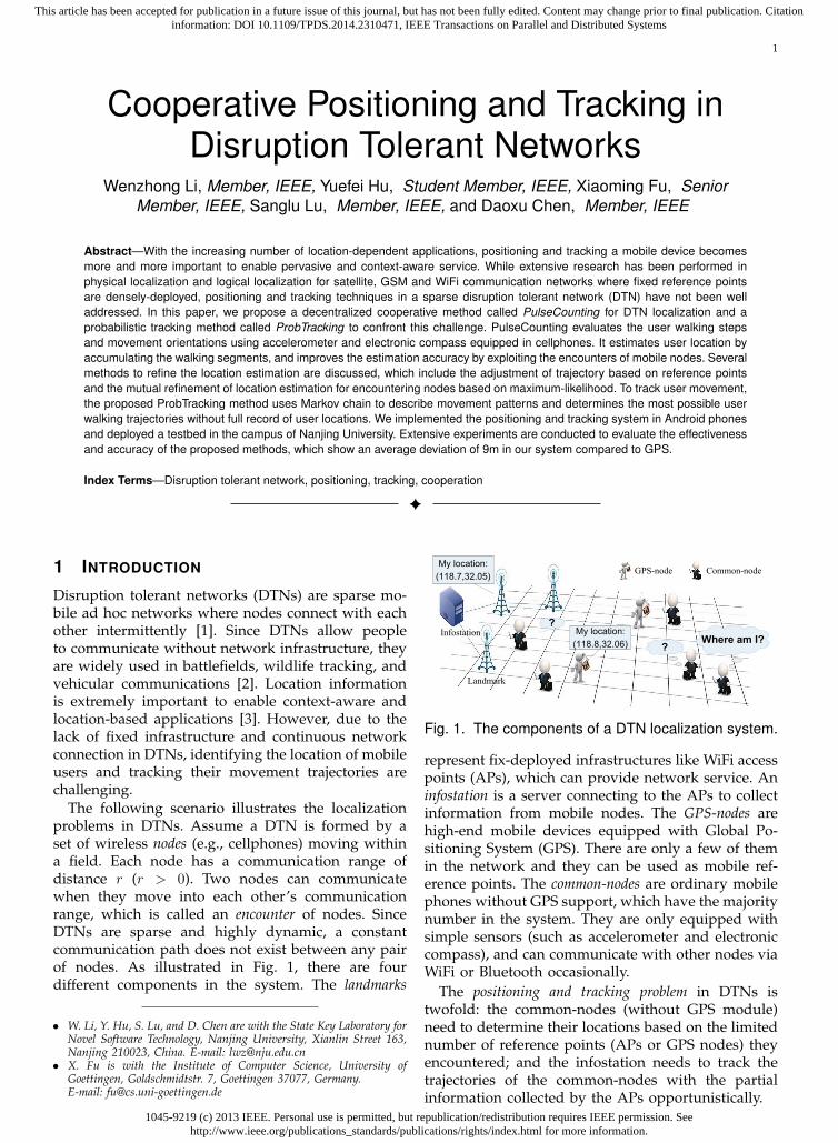
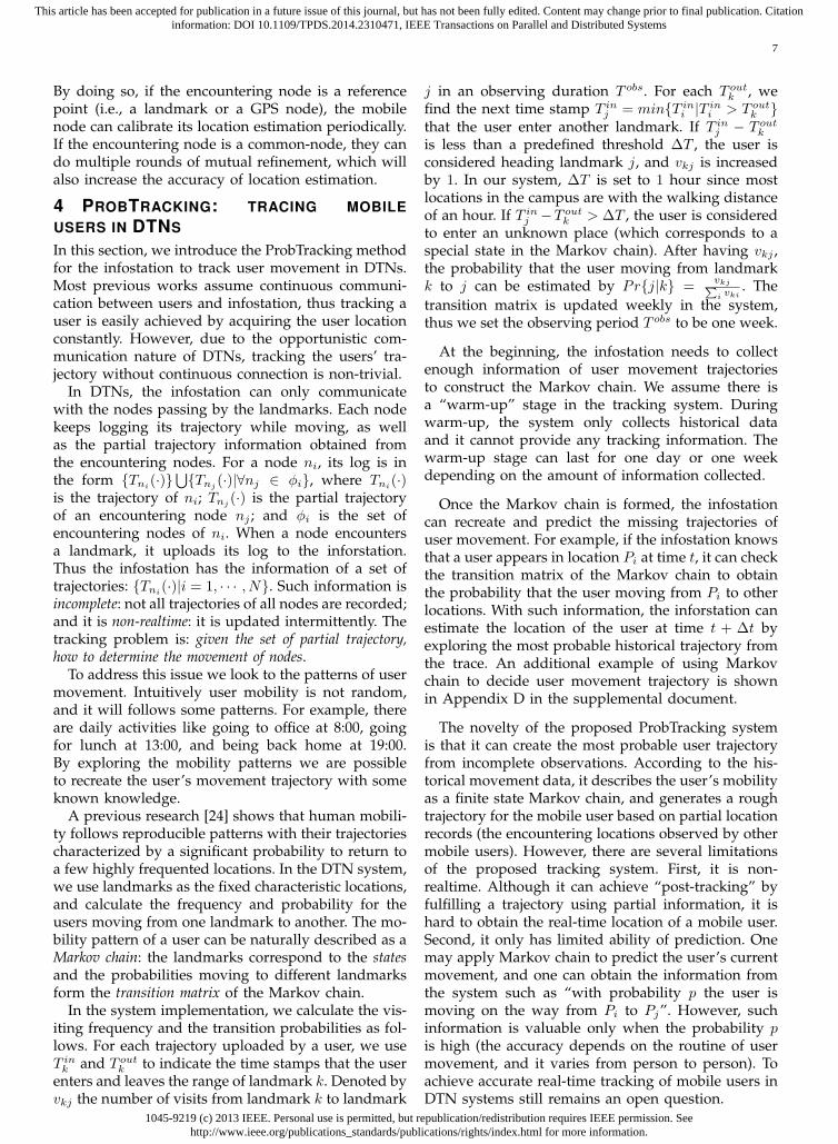
Fig. 6. Experimental scenario in the NJU campus.
5 IMPLEMENTATION AND EVALUATION
In this section, we discuss the implementation issuesand evaluate the system performance.
5.1 ImplementationWe implemented the PulseCounting localizationmethod in the HTC Wildfire phone. The HTC Wild-fire Android smartphone has built-in GPS, WiFi andBluetooth communication modules, as well as sensorssuch as accelerometer and compass. The proposedpositioning system was implemented as an AndroidApp and tested by 12 volunteers.
To track the movement of users, we implement-ed the ProbTracking method in a PC server, whereMySQL and PHP are adopted to store user historicaldata and calculate the movement trajectories. Thetracking service was deployed in an Apache server,and it can be accessed from a web browser withJavaScript.
We deployed a testbed in the Gulou campus of Nan-jing University (NJU) to evaluate the system perfor-mance. The experimental environment is illustratedin Fig. 6. Four APs were deployed in the campuswhich work as landmarks and provide connection toInternet. The chosen landmarks corresponds to fourtypical locations in the campus: P1 (the Department ofComputer Science), P2 (the library), P3 (the Southeastbuilding), and P4 (the academic building).
We design several scenarios to test the system. Asshown in Fig. 6, we specify two routes P1 ↔ P4
(marked by the full white line) and P2 ↔ P3 (markedby the dashed orange line), which represent a longerand a shorter walking paths accordingly. Both routeshave straight sections and turns, and they intersecteach other. The volunteers were asked to walk alongthe two routes back and forth, with the phones placedin their front pockets. The WiFi modules of the s-mart phones were turned on. Some random userswere appointed to play the role of GPS-nodes. Themobile users have the opportunities to encounter onthe straight road or intersections, and their locationestimation are refined dynamically using the methodsproposed in section 3.6. All GPS locations of the users
0.9
0.91
0.92
0.93
0.94
0.95
0.96
0.97
0.98
0.99
1
50m 100m 200m 400m
Accura
cy
User1 User2 User3
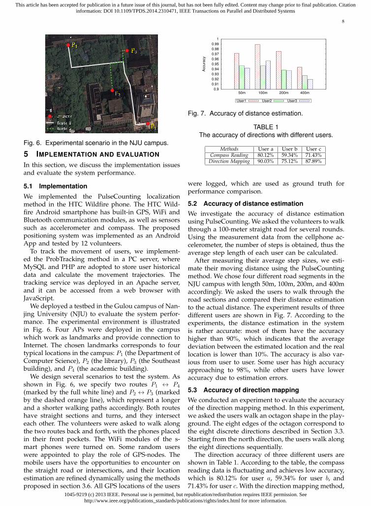
Fig. 7. Accuracy of distance estimation.
TABLE 1The accuracy of directions with different users.
Methods User a User b User cCompass Reading 80.12% 59.34% 71.43%
Direction Mapping 90.03% 75.12% 87.89%
were logged, which are used as ground truth forperformance comparison.
5.2 Accuracy of distance estimationWe investigate the accuracy of distance estimationusing PulseCounting. We asked the volunteers to walkthrough a 100-meter straight road for several rounds.Using the measurement data from the cellphone ac-celerometer, the number of steps is obtained, thus theaverage step length of each user can be calculated.
After measuring their average step sizes, we esti-mate their moving distance using the PulseCountingmethod. We chose four different road segments in theNJU campus with length 50m, 100m, 200m, and 400maccordingly. We asked the users to walk through theroad sections and compared their distance estimationto the actual distance. The experiment results of threedifferent users are shown in Fig. 7. According to theexperiments, the distance estimation in the systemis rather accurate: most of them have the accuracyhigher than 90%, which indicates that the averagedeviation between the estimated location and the reallocation is lower than 10%. The accuracy is also var-ious from user to user. Some user has high accuracyapproaching to 98%, while other users have loweraccuracy due to estimation errors.
5.3 Accuracy of direction mappingWe conducted an experiment to evaluate the accuracyof the direction mapping method. In this experiment,we asked the users walk an octagon shape in the play-ground. The eight edges of the octagon correspond tothe eight discrete directions described in Section 3.3.Starting from the north direction, the users walk alongthe eight directions sequentially.
The direction accuracy of three different users areshown in Table 1. According to the table, the compassreading data is fluctuating and achieves low accuracy,which is 80.12% for user a, 59.34% for user b, and71.43% for user c. With the direction mapping method,

1045-9219 (c) 2013 IEEE. Personal use is permitted, but republication/redistribution requires IEEE permission. Seehttp://www.ieee.org/publications_standards/publications/rights/index.html for more information.
This article has been accepted for publication in a future issue of this journal, but has not been fully edited. Content may change prior to final publication. Citationinformation: DOI 10.1109/TPDS.2014.2310471, IEEE Transactions on Parallel and Distributed Systems
9
P1
(a) Starting.
A
P1
(b) Midway.
P1
P4
(c) Arriving.
Fig. 8. Screen shots of user movement trajectory.
0
5
10
15
20
0 50 100 150 200 250 300 350
Location E
rror
to G
PS
(m
)
Distance (m)
None: 11.60Partial: 9.97
Multiple: 8.61
Fig. 9. Instantaneous deviation compared to GPS.
the accuracy reaches to 90.03% for user a, 75.12%for user b, and 87.89% for user c, which implies asignificant improvement in performance.
5.4 The positioning system
As mentioned above, the proposed cooperative po-sitioning system was implemented as an AndroidApp and installed in the HTC phones. The App canestimate user’s location and demonstrate the movingtrajectory in the screen. Fig. 8 illustrated the screenshots of a user walking from P1 to P4. At the begin-ning, the user leaved P1 and headed north (Fig. 8(a)).In the midway, the user encountered a GPS-node atposition A (Fig. 8(b)). After information exchange, thepositioning system used the received GPS coordinatesto refine his trajectory (from P1 to A). The refinedtrajectory is demonstrated in colored lines in Fig. 8.Thereafter, the user moved towards west, then turnedto the north, and finally arrived the destination P4.Since P4 was a landmark, the latest trajectory (fromA to P4) was refined using the obtained locationinformation, and the updated trajectory was shownin the user’s screen as Fig. 8(c).
To show the accuracy of the positioning system andthe effectiveness of the location refinement methods,we use the GPS logs as ground truth and calculate thedeviation of PulseCounting to GPS during movement.Fig. 9 shows the instantaneous deviation of a randomuser moving from P1 to P4. The “None” data (red cir-cle dots) mean that no refinement is done to the esti-mation. The “Partial” data (green cross dots) indicatesthat the location estimation is refined only using theinformation from other mobile nodes. The “Multiple”data (blue star dots) indicates that the node considersall possible information from landmarks and fromother mobile nodes to refine its location estimation.As shown in the figure, the instantaneous deviation is
P1
P2
P3P4
A
Fig. 10. Screen shots of the tracking system.
fluctuating, which means that the relative estimationerror compared to GPS varies from time to time. Forshorter distance (e.g., shorter than 200m), the threecurves are close to each other. For longer distance(e.g., longer than 200m), the deviation of “None” datais the highest. The location estimation refined by onlymobile node is slightly lower than non-refinement.The location refined by landmarks and mobile nodesachieves the lowest deviation, which is significantlylower than the others.
The average deviations of the three cases are shownbeside their corresponding symbols in Fig. 9. It can beseen that the average deviation of the three methodsare 11.60m, 9.97m, and 8.61m accordingly.
Note that the positioning accuracy depends on thecommunication range of the mobile devices. Theoret-ically the proposed approach is applicable to differentwireless communication techniques including WiFi,BlueTooth, ZigBee, etc, and different communicationtechnique will yield different accuracy accordingly. Inour system, we choose WiFi for implementation sinceit is widely available and equipped in most smartphones. The typical communication range of WiFi isabout 10 meters, and the average accuracy of 9 meters(compared to GPS) is achieved using the proposedpositioning and refinement approaches.
5.5 The tracking system
The tracking system was implemented in a PC server,which was connected to the Internet and could beaccessed via web browsers. The tracking server canemulate the trajectories of mobile nodes and displaytheir traces on the map.
Fig. 10 illustrates the trajectories of two mobilenodes in our experiment. In this scenario, node 1moved from P1 to P4 and node 2 moved from P2
to P3. They encountered at an intersection A. Node 2reached to its destination first (since it walked alonga shorter path). The server collected data from node 2via the AP in P3. Based on the knowledge of historystatistics and the trajectories uploaded by node 2, theserver determined that node 1 was moving to P4
with high probability and infer its movement with ahistorical trajectory. Thus the browser can display the

1045-9219 (c) 2013 IEEE. Personal use is permitted, but republication/redistribution requires IEEE permission. Seehttp://www.ieee.org/publications_standards/publications/rights/index.html for more information.
This article has been accepted for publication in a future issue of this journal, but has not been fully edited. Content may change prior to final publication. Citationinformation: DOI 10.1109/TPDS.2014.2310471, IEEE Transactions on Parallel and Distributed Systems
10
0
5
10
15
20
0 50 100 150 200 250 300 350
Lo
ca
tio
n E
rro
rto
GP
S (
m)
Distance (m)
Tracking trajectory
Fig. 11. Deviation of the tracking system.
walking routes of both users without communicatingwith them in realtime.
Fig. 11 compares the deviation of the tracking trajec-tory to the GPS records. According to the figure, in thewalking distance of 350 meters, the deviation variesfrom 5 meters to 25 meters. The average deviation is12.49 meters. Note that such accuracy achieves onlywhen the system makes a correct prediction of theuser’s route. If the system makes a wrong prediction(based on Markov chain, this will happen with someprobability), the deviation will be far away from thereal trajectory. Improving the prediction accuracy andreducing the tracking errors will be our future work.
5.6 Energy consumption
We evaluate the energy efficiency of the proposedpositioning system, and show that its energy con-sumption is slightly higher than online radio listening,but much lower than online video watching. Thedetails are found in Appendix E in the supplementaldocument.
5.7 Discussion and comparisons
We further discuss the pros and cons of the proposedpositioning and tracking system, and provide compar-isons with other related works such as AAMPL [21],CompAcc [11], and Escort [12]. The details are foundin Appendix F in the supplemental document.
6 CONCLUSION
Localization in DTNs faces two major difficulties: themobile node can only use sparse reference points toestimate its location, and the tracking server needto determine and predict movement trajectories withpartial location information. To overcome these dif-ficulties, we propose PulseCounting and ProbTrackingfor positioning and tracking in DTNs. We implementthe system in Android phones and evaluate its per-formance in a testbed in the NJU campus. Extensiveexperiments show that the proposed system achievesan average deviation less than 9m compared to GPS.
ACKNOWLEDGEMENT
This work was partially supported by the NationalNatural Science Foundation of China (Grant Nos.61373128, 91218302, 61321491), the EU FP7 IRSES Mo-bileCloud Project (Grant No. 612212), and the fundingfrom Alexander von Humboldt Foundation.
REFERENCES[1] K. Fall, “A delay-tolerant network architecture for challenged
internets,” in Proc. of SIGCOMM ’03. ACM, 2003, pp. 27–34.[2] A. Lindgren, A. Doria, E. Davies, and S. Grasic, “Probabilistic
routing protocol for intermittently connected networks,” RFC6603, Internet Research Task Force (IRTF), Aug. 2012.
[3] S. Gaonkar, J. Li, R. R. Choudhury, L. Cox, and A. Schmidt,“Micro-blog: sharing and querying content through mobilephones and social participation,” in Proc. of MobiSys ’08.ACM, 2008, pp. 174–186.
[4] E. D. Kaplan, Understanding GPS Principles and Applications.Artech House Publishers, Feb 1996.
[5] J. Soubielle, I. Fijalkow, P. Duvaut, and A. Bibaut, “GPSpositioning in a multipath environment,” IEEE Transactions onSignal Processing, vol. 50, no. 1, pp. 141–150, Jan 2002.
[6] J. Yang, A. Varshavsky, H. Liu, Y. Chen, and M. Gruteser,“Accuracy characterization of cell tower localization,” in Proc.of Ubicomp ’10. ACM, 2010, pp. 223–226.
[7] M. Y. Chen, T. Sohn, D. Chmelev, D. Haehnel, J. Hightower,J. Hughes, A. LaMarca, F. Potter, I. Smith, and A. Varshavsky,“Practical metropolitan-scale positioning for gsm phones,” inProc. of UbiComp’06. Springer-Verlag, 2006, pp. 225–242.
[8] P. Bahl and V. N. Padmanabhan, “RADAR: An in-building rf-based user location and tracking system,” in Proc. of Infocom’00.IEEE, 2000, pp. 775–784.
[9] A. LaMarca, Y. Chawathe, S. Consolvo, J. Hightower, I. Smith,J. Scott, T. Sohn, J. Howard, J. Hughes, F. Potter, J. Tabert,P. Powledge, G. Borriello, and B. Schilit, “Place lab: devicepositioning using radio beacons in the wild,” in Proc. ofPERVASIVE’05. Springer-Verlag, 2005, pp. 116–133.
[10] M. Azizyan, I. Constandache, and R. Roy Choudhury, “Sur-roundsense: mobile phone localization via ambience finger-printing,” in Proc. of MobiCom ’09. ACM, 2009, pp. 261–272.
[11] I. Constandache, R. R. Choudhury, and I. Rhee, “Towardsmobile phone localization without war-driving,” in Proc. ofINFOCOM’10. IEEE Press, 2010, pp. 2321–2329.
[12] I. Constandache, X. Bao, M. Azizyan, and R. R. Choudhury,“Did you see bob?: human localization using mobile phones,”in Proc. of MobiCom ’10. ACM, 2010, pp. 149–160.
[13] N. Banerjee, M. D. Corner, and B. N. Levine, “Design and fieldexperimentation of an energy-efficient architecture for dtnthrowboxes,” IEEE/ACM Transactions on Networking, vol. 18,no. 2, pp. 554–567, 2010.
[14] Y. Li, Y. Jiang, D. Jin, L. Su, L. Zeng, and D. Wu, “Energy-efficient optimal opportunistic forwarding for delay-tolerantnetworks,” IEEE Transactions on Vehicular Technology, vol. 59,no. 9, pp. 4500–4512, Nov 2010.
[15] Y. Li, P. Hui, D. Jin, L. Su, and L. Zeng, “Evaluating the impactof social selfishness on the epidemic routing in delay tolerantnetworks,” IEEE Communications Letters, vol. 14, no. 11, pp.1026–1028, November 2010.
[16] P. Hui, K. Xu, V. Li, J. Crowcroft, V. Latora, and P. Lio,“Selfishness, altruism and message spreading in mobile socialnetworks,” in Proc. of INFOCOM Workshops ’09, April 2009.
[17] S. Gezici, “A survey on wireless position estimation,” WirelessPersonal Communications, vol. 44, no. 3, pp. 263–282, Feb. 2008.
[18] S. Sen, B. Radunovic, R. R. Choudhury, and T. Minka, “Youare facing the mona lisa: spot localization using phy layerinformation,” in Proc. of MobiSys ’12. ACM, 2012, pp. 183–196.
[19] H. Liu, Y. Gan, J. Yang, S. Sidhom, Y. Wang, Y. Chen, and F. Ye,“Push the limit of wifi based localization for smartphones,” inMobicom ’12. ACM, 2012, pp. 305–316.
[20] Z. Yang, C. Wu, and Y. Liu, “Locating in fingerprint space:wireless indoor localization with little human intervention,”in Proc. of Mobicom ’12. ACM, 2012, pp. 269–280.
[21] A. Ofstad, E. Nicholas, R. Szcodronski, and R. R. Choudhury,“AAMPL: accelerometer augmented mobile phone localiza-tion,” in Proc. of MELT ’08. ACM, 2008, pp. 13–18.
[22] Google, “The google map,” https://maps.google.com/, 2012.[23] S. Boyd and L. Vandenberghe, Convex Optimization. Cam-
bridge University Press, March 2004.[24] M. C. Gonzalez, C. A. Hidalgo, and A.-L. Barabasi, “Under-
standing individual human mobility patterns,” Nature, vol.453, pp. 779–782, June 2008.
1045-9219 (c) 2013 IEEE. Personal use is permitted, but republication/redistribution requires IEEE permission. Seehttp://www.ieee.org/publications_standards/publications/rights/index.html for more information.
This article has been accepted for publication in a future issue of this journal, but has not been fully edited. Content may change prior to final publication. Citationinformation: DOI 10.1109/TPDS.2014.2310471, IEEE Transactions on Parallel and Distributed Systems
11
Wenzhong Li received his B.S. and Ph.Ddegree from Nanjing University, China, bothin computer science. He was a HumboldtScholar at the University of Gottingen, Ger-many. He is now an associate professor inthe Department of Computer Science, Nan-jing University. Dr. Li’s research interests in-clude wireless networks, pervasive comput-ing, and social networks. He has publishedover 40 research papers at international con-ferences and journals, which include ICDCS,
IWQoS, ICPP, ICC, WCNC, IEEE Transactions on Wireless Com-munications, IEEE Transactions on Vehicular Technology, etc. Dr. Liwas also the winner of the Best Paper Award of ICC 2009. He is amember of IEEE and ACM.
Yuefei Hu received his B.S. degree inComputer Science from Jilin University,Changchun, China, and received his M.s.degree in Computer Science from NanjingUniversity, Nanjing, China. He is now work-ing as a staff in the Zhengzhou CommodityExchange, one of the four futures exchangesin China. His research interests include datarouting in wireless sensor networks, wirelessmedia streaming system and localization indelay tolerant networks.
Xiaoming Fu received his bachelor andmaster degrees from Northeastern Univer-sity, China, and his Ph.D. degree from Ts-inghua University, Beijing, China. He wasa research staff at the Technical Univer-sity Berlin until joining the University ofGottingen, Germany in 2002, where he hasbeen a professor in computer science andheading the Computer Networks Group since2007. His research interests include networkarchitectures, protocols, and applications. He
is currently an editorial board member of IEEE CommunicationsMagazine, IEEE Transactions on Network and Service Management,Elsevier Computer Networks, and Computer Communications, andhas published over 100 papers in journals and international confer-ence proceedings. He is the coordinator of EU FP7 GreenICN andMobileCloud projects, and the recipient of the IEEE LANMAN 2013Best Paper Award and the 2005 University of Gottingen FoundationAward for Exceptional Publications by Young Scholars.
Sanglu Lu received her B.S., M.S., andPh.D. degrees from Nanjing University in1992, 1995, and 1997, respectively, all incomputer science. She is currently a pro-fessor in the Department of Computer Sci-ence and Technology and the deputy directorof State Key Laboratory for Novel SoftwareTechnology. Her research interests includedistributed computing, pervasive computing,and wireless networks. She is a member ofIEEE and ACM.
Daoxu Chen was a visiting professor in Pur-due University and City University of HongKong. He is now a professor in the Depart-ment of Computer Science, Nanjing Univer-sity. His research interests include distribut-ed computing, parallel processing, and com-puter networks. He has published over 100research papers in international conferenceproceedings and journals. He is a memberof IEEE, ACM and a senior member of theChina Computer Federation.


![Positioning Algorithm for Deployment of Femtocell Network ... · Figure 1. Femtocell via mobile network connection [3] The cooperative positioning approach will have allowed the increase](https://img.pdfslide.net/doc/110x75/5c90d62409d3f2c8148bf51c/positioning-algorithm-for-deployment-of-femtocell-network-figure-1-femtocell.jpg)