Embed Size (px)
Citation preview
Chapter 6
Coordinate Systems
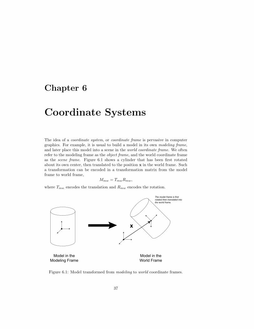
The idea of a coordinate system, or coordinate frame is pervasive in computergraphics. For example, it is usual to build a model in its own modeling frame,and later place this model into a scene in the world coordinate frame. We oftenrefer to the modeling frame as the object frame, and the world coordinate frameas the scene frame. Figure 6.1 shows a cylinder that has been first rotatedabout its own center, then translated to the position x in the world frame. Sucha transformation can be encoded in a transformation matrix from the modelframe to world frame,
Mmw = TmwRmw,
where Tmw encodes the translation and Rmw encodes the rotation.
Model in the Modeling Frame
Model in the World Frame
The model frame is first rotated then translated into the world frame.
x
Figure 6.1: Model transformed from modeling to world coordinate frames.
37

38 CHAPTER 6. COORDINATE SYSTEMS
6.1 Left and right handed coordinate frames
x
y
z
Let us develop the idea of a coordinate frame and how we canconstruct them for use in computer graphics. A 3D coordinateframe might be drawn as shown in the diagram to the right. Thethree axes are understood to be at right angles (orthogonal) toeach other. In the figure, x denotes the horizontal axis, y thevertical axis, and z the depth axis (coming out of the page).This the usual right-handed coordinate system seen in ComputerGraphics.
The coordinate system shown above is called right handed, sinceif you place your thumb, index finger and the middle finger ofthe right hand at right angles to each other, as demonstrated in Figure 6.2,they look like coordinate axes. The thumb represents the x axis, the indexfinger represents the y axis, and the middle finger represents the z axis. As canbe seen from the figure, when done with the left hand, the z axis, is reversed,measuring depth into the page.
x
y
zx
yz
Left Hand System Right Hand System
Figure 6.2: Left handed vs. right handed coordinate frames.
6.2 Coordinate frame expressed as a point andorthogonal unit vectors
uz
oux
uy
In any coordinate system, the position where the coordinateaxes cross is called the origin, and by definition has the coor-dinates O = (0, 0, 0) in that coordinate system. In order towork with the coordinate frames in the algebraic language ofvectors and matrices, we can re-label the axes of the coordi-
6.3. CREATING COORDINATE FRAMES 39
nate system with unit vectors directed along the coordinatedirections, as shown in the diagram to the right. We use thenotation ux to represent a unit vector in the x direction, uy
in the y direction, and uz in the z direction. With this notation, a 3D pointp = (px, py, pz) in this coordinate frame can be rewritten
p = O + pxux + pyuy + pzuz.
Now, if we wish to rotate our coordinate frame we can simply apply a rotationmatrix to the vectors ux, uy, and uz, and if we wish to translate the frame wecan apply a translation matrix to O.
A trick is to represent vectors in homogeneous coordinates on the plane w = 0and points on the plane w = 1. For example, a surface normal vector might be
written n =
nxnynz0
, while a point might be written p =
pxpypz1
. If we are
consistent with this notation, then a rotation matrix will affect both points andvectors, but a translation matrix will affect only points. For example
1 0 0 4x0 1 0 4y0 0 1 4z0 0 0 1
nxnynz0
=
nxnynz0
,but
1 0 0 4x0 1 0 4y0 0 1 4z0 0 0 1
pxpypz1
=
px +4xpy +4ypz +4z
1
.A transformation matrix that first rotates and then translates will then workperfectly for transforming both vectors and points in one frame to another frame.Thus, to transform from one frame to another frame we have a choice. We caneither transform the coordinate frame itself, representing this transformation bya matrix, and leave all of the points and normals in the original coordinate frame.Or, we can transform all the points and normals from the original frame to thenew frame. The latter approach is referred to as ”baking” the transformation.
6.3 Creating coordinate frames
If we have two vectors in space and an origin point we can conveniently constructa coordinate frame by using the vector cross product operation. Let us say thatwe have the vectors a and b, and compute their cross product a× b as shownin Figure 6.3. The cross product vector is perpendicular to both a and b.

40 CHAPTER 6. COORDINATE SYSTEMS
b
ab
aa x b
Figure 6.3: a× b is a vector orthogonal to both a and b.
Figure 6.4 shows a coordinate frame construction made using this observation.We can arbitrarily pick either a or b to represent one of the coordinate axes.For example, in the figure we have chosen a to be aligned with the x direction.Thus, ux = a/‖a‖ is the unit vector in the direction of a. Since a × b will beperpendicular to both a and b, it must be aligned with one of the other axes,for example the z axis. Thus, uz = (a× b)/‖a× b‖. Finally, the y axis, whichmust be perpendicular to both the x and z axes, is simply uy = uz × ux.
b
aux
uyuz
Figure 6.4: A coordinate frame constructed from the vectors a and b.
Once we have the three unit vectors describing the coordinate frame, it is easyto turn these into a rotation matrix that transforms from the current frame tothis new frame. The matrix
R =[
ux uy uz
],
whose columns are the three unit vectors, will do this. You can demonstrate toyourself that this matrix works, since it rotates the three coordinate axes intothese new vectors:
R
100
= ux, R
010
= uy, and R
001
= uz.
And, we know that this matrix is doing only a pure roation since ux,uy,uz aremutually orthogonal unit vectors. This is exactly the condition that must holdfor a matrix to describe a pure rotation.
To complete the description of the transform from the current frame to the newframe, we also need to provide a translation from the old origin to the neworigin. Again, this can be built into a matrix and multiplied into the matrix Ron the left.