Embed Size (px)
Citation preview

20
Using Oracle Spatial with Coordinate Systems Based on Any Regional Geodetic Datum
Christian MANTHE, Christian CLEMEN, Lothar GRÜNDIG, Germany
Key words: geodetic datum, coordinate systems, oracle spatial SUMMARY Oracle Spatial supports many geodetic and non-geodetic coordinate systems, e.g. as defined by the European Petroleum Survey Group (EPSG) data model. Whereas the spheroid dimensions and the algorithms for the projection are well known and implemented (in most cases) the geodetic datum consists of estimated quantities as this transformation is based on multiple reference points. For historical reasons and due to only local updating, the given standard parameter for coordinate systems is often not good enough with respect to the accuracy of transformed homological points. This article illustrates the relations of the Oracle Spatial data model that specifies a geodetic datum including tables for spheroid dimensions, projection types and spheroid displacements. It is described how to insert and update a geodetic datum. Essential steps for data-conversion, estimation and validation of the transformation parameters and data base implementation are comprehensively explained by means of an example covering the German Berlin State Coordinate System (Netz88). 1. INTRODUCTION More and more data are available from a variety of different sources, and more and more people have the means and the need to make use of it. A situation now exists where using a reference system for the means of acquiring data being completely different from the one in which the data will ultimately be required is quite common. This is a particular problem of combining data sets, in which new data is to be put alongside archive material or of combining an image referenced with GPS with others that have been obtained from published map. Those are different data in different coordinate systems. To combine those data one set has to be transformed into the other. So the combining problem is foremost a transformation problem. This article by way of an example explains the steps in a user-defined coordinate transformation with parameter estimation in Oracle. In Oracle Spatial two different ways exist to solve such a problem. On the one hand we can use stored procedures. Here the complete formalism for the transformation between two data sets is to be implemented into a single procedure. This will be a quick solution as long as we have only one target system and not very complex formulas. The disadvantage is that this stored procedure is not reusable with different systems.

21
On the other hand we can use the features of Oracle Spatial. There we only need some general information about the system and some homological points to estimate the datum parameter. From this we can define the coordinate systems used for the available data sets in Oracle. Finally we apply the given implemented procedures to transform our data sets. The advantage here is that we can transform data with an easily-programmed SQL-statement for most of the given coordinate systems by using the SDO_GEOMERY in Oracle see (Kothuri & Godfrind & Beinat, 2007) or (Oracle, 2007). select I.PKTNUM Punkt, SDO_CS.TRANSFORM(I.geom ,83033).sdo_point.x x, SDO_CS.TRANSFORM(I.geom ,83033).sdo_point.y y from SOLDNER_BLN I;
listing 1: transform Soldner Berlin coordinates into UTM ETRS89 In order to define a coordinate system in Oracle, we first explain some basics of coordinate systems and transformations in section 2. The data model for setting coordinate systems is explained in section 3. Section 4 deals with the estimation of the datum parameters. The SQL statements used to set the special Berlin Soldner coordinate system are given in section 5. 2. OVERVIEW OF COORDINATE SYSTEMS Basically we can classify coordinate systems in projected and geodetic coordinate systems. Geodetic coordinate systems are referring to spheroids, that can be spherical but mostly are elliptical. The geometric parameter semi-major and semi-minor axis and also the orientation of the ellipsoid (translation and rotation) with respect to a geocentric system define the geodetic datum of a system. To transform coordinates between two different geodetic systems they must first be converted into 3-dimensional world coordinates. In a second step they are to be transformed by a Helmert-transformation into the target world coordinate system. After that they will finally be converted with the given target ellipsoid into the required target geographic coordinates. Projected coordinate systems are used for practical reasons. In surveying mostly UTM projection (figure 1) is used because of its metric and conformal features. All projections share definite mathematical rules. So a projected coordinate system is always a mapped geodetic coordinate system. Conversions between geographic and projected coordinates are mathematically clearly defined. In Oracle several projections are implemented. The user only needs to choose the specific parameters of the projection e.g. scale factor, geographic coordinates of the origin or central meridian and offsets. Those kinds of parameters usually are known.

22
Fig. 1: UTM projection
Because of the historical development in geodesy there exist diverse rotation ellipsoids. These can be orientated differently with respect to their realized local reference frame. In Germany for example we have a common general geodetic system called DHDN (German general triangulation net) for the country as a whole, but with different realizations in the different states. Those can be traced back to individual improvements in the local net evaluation. GPS facilitates investigating a global best-approximated rotation ellipsoid (see figure 2). The most recent global geocentric datum is the World Geodetic System 1984 (WGS84) and for Europe the European Terrestrial Reference Frame 1989 (ETRF89), both with identical orientation parameters and with the origin in the mass centre of our earth.
Fig. 2: Spheroid displacements
To obtain a precise transformation result we have to know the specific orientation parameters of the ellipsoid used. A way to estimate these parameters is explained in section 4 but first let’s see how Oracle deals with coordinate systems.

23
3. COORDINATE SYSTEMS IN ORACLE The data model in Oracle is based on the European Petroleum Survey Group (EPSG) data model and data set, but it is not completely identical with it. Coordinate systems are described in table SDO_COORDREF_SYS. Via foreign keys all information needed is linked with that table (see figure 3).
3.1 Overview
Oracle distinguishes coordinate systems in the following categories: 1-dimensional VERTICAL, 2-dimensional PROJECTED, GEOGRAPHIC2D and 3-dimensional GEOCENTRIC, GEOGRAPHIC3D and COMPOUND coordinate systems.
VERTICAL: for defining physical height systems GEODETIC: for defining coordinate systems based on a individual reference surface PROJECTED: for defining a coordinate system based on a geodetic system COMPOUND: for defining a projected system with physical height
Typically the geocentric coordinate systems are predefined in Oracle. So we only have to answer the question of instantiate an unknown local system in Oracle. For the later illustration of this we explain here the features of the local Soldner Berlin system.
3.2 Features of the local Soldner Berlin System
Due to the history and the location of Berlin between two different projection zones the Berlin Soldner system is still official. It represents a coordinate system with a special very easy-to-use non-conformal projection developed by the German scientist Johann Georg Soldner in the 19th century. The projection used is also well-known and predefined in Oracle as Cassini projection, which was developed in the18th century by Dominique Cassini in France. The features of the Berlin Soldner projection are the geodetic coordinates of the origin “Müggelberg” latitude of origin = 52.41864827777778° and Central meridian = 13.62720366666667°, the shift of the origin (false easting 40km and false northing = 10km, made to eliminate negative coordinates called false easting and false northing) and the scale factor.
The underlying geodetic system is called “Netz88” and uses the Bessel rotation ellipsoid as reference surface. It is based on the “Deutsche Hauptdreiecksnetz” (DHDN). The DHDN system is defined so that the vertical deflection in the fundamental point in Rauenberg is zero. This results in the ellipsoid (see figure 2) fitting very well in Germany as a whole (best fitting nationwide).

24
Based on the DHDN, the new net adjustment solution with new terrestrial and GPS supported observations in the area of Berlin is called “Netz88” (best fitting state-wide). So the Net88 has different datum parameters from DHDN and even from the geocentric geodetic system. 4. ESTIMATION OF THE ORIENTATION PARAMETERS For estimating the ellipsoid orientation parameter we need homologous points. These points are known in the local and in the target (in Oracle: ETRS89) coordinate systems. In order to prepare the estimation, the point information in both systems has to be converted into 3D xyz-world coordinates with respect to the projection and the underlying ellipsoid. 4.1 Used points For the parameter estimation 14 homologous points were used. These are known in the local Soldner Berlin System and the global ETRS89. All points were evenly spread over the area of Berlin to detect possible distortions in the local system. 4.2 Assumptions We used only 2D-Soldner Berlin coordinates. Height information was not considered. Solving the problem in an easy way, the ETRS89 coordinates are considered as non-stochastic errorless values and the coordinate system is expected to be nearly homogeneous. Based on these restrictions we have to estimate seven parameters (three rotations, three translations and the scale). 4.3 Pre-processing to estimate the datum parameters To estimate the transformation parameter needed, the coordinates of both systems must be converted into 3D-world coordinates. Therefore initially the given coordinates were projected back into geodetic coordinates with given formulas (EPSG, 2009). This means that the projected 2D-coordinates were converted into 2D-geodetic coordinates on the reference surface of the underlying ellipsoid. In a second step the geodetic coordinates must be calculated into 3D-world coordinates observing the geometry of the ellipsoid used (Bessel 41 for Berlin Soldner and GRS80 for ETRS89). As the origin of the ETRS89 is defined in the middle of the centre of mass these coordinates are called “geocentric.” Finally, we determined a parameter description of our local best fitted 3D-coordinate system with respect to the spatial geocentric system.
25
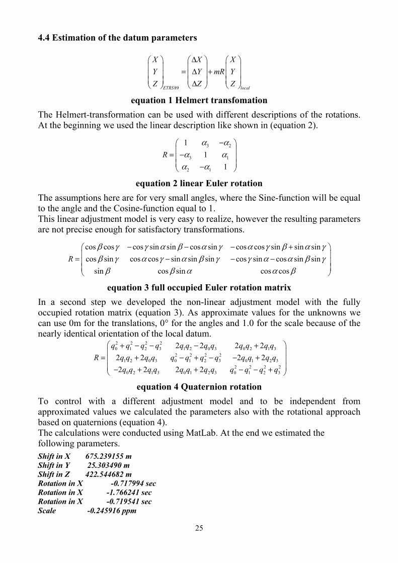
4.4 Estimation of the datum parameters
89ETRS local
X X XY Y mR YZ Z Z
∆ = ∆ + ∆
equation 1 Helmert transfomation The Helmert-transformation can be used with different descriptions of the rotations. At the beginning we used the linear description like shown in (equation 2).
3 2
3 1
2 1
11
1R
α αα αα α
− = − −
equation 2 linear Euler rotation The assumptions here are for very small angles, where the Sine-function will be equal to the angle and the Cosine-function equal to 1. This linear adjustment model is very easy to realize, however the resulting parameters are not precise enough for satisfactory transformations.
cos cos cos sin sin cos sin cos cos sin sin sincos sin cos cos sin sin sin cos sin cos sin sin
sin cos sin cos cosR
β γ γ α β α γ α γ β α γβ γ α γ α β γ γ α α β γβ β α α β
− − − + = − − −
equation 3 full occupied Euler rotation matrix In a second step we developed the non-linear adjustment model with the fully occupied rotation matrix (equation 3). As approximate values for the unknowns we can use 0m for the translations, 0° for the angles and 1.0 for the scale because of the nearly identical orientation of the local datum.
2 2 2 20 1 2 3 1 2 0 3 0 2 1 3
2 2 2 21 2 0 3 0 1 2 3 0 1 2 3
2 2 2 20 2 1 3 0 1 2 3 0 1 2 3
2 2 2 22 2 2 22 2 2 2
q q q q q q q q q q q qR q q q q q q q q q q q q
q q q q q q q q q q q q
+ − − − + = + − + − − + − + + − − +
equation 4 Quaternion rotation To control with a different adjustment model and to be independent from approximated values we calculated the parameters also with the rotational approach based on quaternions (equation 4). The calculations were conducted using MatLab. At the end we estimated the following parameters.
Shift in X 675.239155 m Shift in Y 25.303490 m Shift in Z 422.544682 m Rotation in X -0.717994 sec Rotation in X -1.766241 sec Rotation in X -0.719541 sec Scale -0.245916 ppm

26
To obtain an adequate description of the implementation, we considered the SQL-statements in the inverse order. By defining our own user-defined system one would consider starting with tables without an undefined foreign key. The following SQL-statements only shows the important lines with descriptions. For detailed information see (Oracle, 2007) and (figure 3).
Fig. 3: Oracle spatial coordinate system data model overview
5. SQL-SCRIPT TO IMPLEMENT THE BERLIN SOLDNER SYSTEM
In the first statement we defined a coordinate system in the SDO_COORD_REF_SYS table. SDO_COORD_REF_SYSTEM is a view of the SDO_COORD_REF_SYS table in with we inserted an entry with the name (COORD_REF_SYS_NAME) “Soldner Berlin” with identification number (SRID)

27
7000001 (bigger then 1000000 because of the self-definition), system kind (COORD_REF_SYS_KIND) as projected, the representation of the coordinates as Cartesian with the unit meter (COORD_SYS_ID), no datum because of the projected system (DATUM_ID), with a specific underlying geodetic system and its datum (SOURCE_GEOG_SRID, GEOG_CRS_DATUM_ID)and the specific Berlin projection (PROJECTION_CONV_ID).
INSERT INTO MDSYS.SDO_COORD_REF_SYSTEM … VALUES ( 7000001 , -- SRID 'Soldner coordinates (Berlin)' , -- COORD_REF_SYS_NAME 'PROJECTED' , -- COORD_REF_SYS_KIND 4530 , -- COORD_SYS_ID NULL , -- DATUM_ID 6000000 , -- GEOG_CRS_DATUM_ID 7000000 , -- SOURCE_GEOG_SRID 5000000 , -- PROJECTION_CONV_ID …
); The underlying geodetic system can be implemented in the following statement into the same view. The features of this system are the different names by SRID. The type of this system is called geographic but also means geodetic. Coordinates are represented as ellipsoidal latitudes and longitudes in decimal degrees. Under the Datum_ID 6000000 the specific Berlin Netz88 Datum is defined. Due to the features of the geodetic system there are no source systems with a Datum or a projection (GEOG_CRS_DATUM_ID = SOURCE_GEOG_SRID = PROJECTION_ CONV_ID = NULL). INSERT INTO MDSYS.SDO_COORD_REF_SYSTEM … VALUES ( 7000000 , -- SRID 'Geodetic coordinates Netz88 (Berlin)' , -- COORD_REF_SYS_NAME 'GEOGRAPHIC2D' , -- COORD_REF_SYS_KIND 6422 , -- COORD_SYS_ID 6000000 , -- DATUM_ID NULL , -- GEOG_CRS_DATUM_ID NULL , -- SOURCE_GEOG_SRID NULL , -- PROJECTION_CONV_ID
… );
In the next step the specific Soldner Berlin projection has to be defined. At first we had to look into the SDO_COORD_OP_METHODS table to check the given

28
projections. Usually we find the Soldner projection under the name Cassini with the COORD_OP_METHOD_ID= 9806. So we do not needed to implement the mathematics of this projection and could start with defining the projection needed under a special COORD_OP_ID in the SDO_COORD_OPS table. The projection type here is a normal conversion of the geodetic system into the projected system and back.
INSERT INTO MDSYS.SDO_COORD_OPS … VALUES ( 5000000 , -- COORD_OP_ID 'Soldner Berlin' , -- COORD_OP_NAME 'CONVERSION' , -- COORD_OP_TYPE
… 9806 , -- COORD_OP_METHOD_ID …
);
To find out which parameters are needed to describe a Soldner projection, the next statement can be used. For more information see (Kothuri & Godfrind & Beinat, 2007).
SELECT use.parameter_id || ': ' || use.legacy_param_name FROM sdo_coord_op_param_use use WHERE use.coord_op_method_id = 9806; As a result we got the PARAMETER_ID´s of the Soldner projection which are. 8801: Latitude_Of_Origin 8802: Central_Meridian 8806: False_Easting 8807: False_Northing Each parameter value has to be set into the SDO_COORD_OP_PARAM_VALS table with the same projection and method number. Also interesting is the unit of the parameter, e.g. decimal degree (UOM_ID=10001) for parameters 8801 and 8802 and meter (UOM_ID=9001) for 8806 and 8807. INSERT INTO MDSYS.SDO_COORD_OP_PARAM_VALS … VALUES ( 5000000 , -- COORD_OP_ID

29
9806 , -- COORD_OP_METHOD_ID 8801 , -- PARAMETER_ID 52.41864827777778, -- PARAMETER_VALUE NULL , -- PARAM_VALUE_FILE_REF 10001 -- UOM_ID ); In the SDO_DATUMS table the Datum parameters as calculated are defined. At first we set a new Datum number and name. Then we chose the datum type, the Bessel-ellipsoid and the meridian of Greenwich as the prime meridian. The next two lines INFORMATION_SOURCE and DATA_SOURCE contain statements which are only informative for the user of this datum. Essential are the lines with the transformation parameters. They are the units for translations in meters, for rotations in seconds and for the scale factor in parts per million that are important to be mentioned here. INSERT INTO MDSYS.SDO_DATUMS
… VALUES ( 6000000 , -- DATUM_ID 'Netz88 (Berlin)', -- DATUM_NAME 'GEODETIC' , -- DATUM_TYPE 8004 , -- ELLIPSOID_ID 8901 , -- PRIME_MERIDIAN_ID 'IGG TU Berlin' , -- INFORMATION_SOURCE 'IGG TU Berlin' , -- DATA_SOURCE 675.239155 , -- SHIFT_X in [m] 25.303490 , -- SHIFT_Y in [m] 422.544682 , -- SHIFT_Z in [m] -0.717994 , -- ROTATE_X in [sec] -1.766241 , -- ROTATE_Y in [sec] -0.719541 , -- ROTATE_Z in [sec] -0.245916 , -- SCALE in [ppm] … ); Finally, the Steps in the overview are:
1. collect all information needed to define the local coordinate system 2. estimate the best datum parameter by using homologous points applying
adjustment calculation 3. Insert the new coordinate system with all needed information into the data
model 4. Paste the orginal coordinates into the SDO-Geometry with the link of the new
coordinate system see at (Oracle, 2007) or (Kothuri & Godfrind & Beinat, 2007)
5. Transform the coordinates into different systems only by changing the SRID number of the target system (listing 1)

30
REFERENCES Kothuri ,R. & Godfrind, A. & Beinat, E. (2007). Pro Oracle Spatial for Oracle Database 11g. Apress. Oracle. (2007). Oracle Spatial Developer´s Guide 11g. from http://www.oracle.com. EPSG. (2009). Coordinate Conversions and Transformation including Formulas. From http://wwwepsg.com. Iliffe, J. (2005). Datums and map porjections. Glasgow: Bell & Bain Ltd. Ghilani, C.D. & Wolf, P. R. (1998). Surveving Theory and Practice. Boston: McGraw-Hill. Hanson, A.J. (2006). Visualisation Quarternions. San Francisco: Morgen Kaufmann. Niemeier, W. (2002). Ausgleichungsrechung. Berlin: de Gruyter. CONTACTS Christian Manthe Technische Universitaet Berlin Institute for Geodesy and Geoinformation Science Chair of Engineering Surveying and Adjustment Techniques Seretariat H20 Strasse des 17. Juni 135 10623, Berlin GERMANY Tel: +49-30-314-24147 Fax: +49-30-314-21119 Email: [email protected] Web site: http://www.geodesy.tu-berlin.de Christian Clemen Technische Universitaet Berlin Institute for Geodesy and Geoinformation Science Chair of Engineering Surveying and Adjustment Techniques Seretariat H20 Strasse des 17. Juni 135 10623, Berlin GERMANY Tel: +49-30-314-26483 Fax: +49-30-314-21119 Email: [email protected] Web site: http://www.geodesy.tu-berlin.de Prof. Dr.-Ing. Dr. h. c. Lothar Gründig Technische Universitaet Berlin Institute for Geodesy and Geoinformation Science Chair of Engineering Surveying and Adjustment Techniques Seretariat H20 Strasse des 17. Juni 135 10623, Berlin GERMANY Tel: +49-30-314-22375 Fax: +49-30-314-21119 Email: [email protected] Web site: http://www.geodesy.tu-berlin.de
© Christian Manthe, Christian Clemen, Lothar Gründig, 2009