Embed Size (px)
Citation preview
International Journal on Electrical Engineering and Informatics ‐ Volume 5, Number 3, September 2013
Coordinated Design of PSS withMultiple FACTS Controllersusing Advanced Adaptive PSO
Rajendraprasad Narne and Prafulla Chandra Panda
Department of Electrical Engineering, National Institute of Technology, Rourkela, Orissa, India
Abstract: This study presents coordinated control tuning of power system stabilizer (PSS) with series and shunt FACTS controllers. Here thyristor controlled series compensator (TCSC) and static synchronous compensator (STATCOM) based controllers are coordinated to enhance the damping of power oscillations and to improve voltage stability. The design of proposed damping controller is formulated as an optimization problem and the controller gains of a non-linear power system are optimized instantaneously using advanced adaptive particle swarmoptimization (AAPSO). Here the power system employed with PSS,TCSC and STATCOM. To compare the performance of proposed controller four different control schemes employed on test power system. Finally, the proposed coordinated controller performance is discussed with time domain simulations. Wide ranges of loading conditions are employed on the test system to test the robustness of proposed coordinate controller and the simulation results are compared with different control schemes. Keywords: Coordinated design, Particle swarmoptimization, STATCOM, PSS, TCSC.
1. Introduction Power oscillations damping in power system is one of the major challenges to the electrical utilities. Stability (damping) of these oscillations depends on the strength of the transmission system as seen by the power plant, generator excitation control systems and plant output [1]. In order to damp these power system oscillations and increase system stability, one of the conventional, economical and effective solutions is to install the power system stabilizer (PSS) [2-3]. However, the use of PSSs only may not be, in some cases, effective in providing sufficient damping for power oscillations, specifically for long distance power transmission. The concept of flexible AC transmission systems (FACTS) has been feasible due to the application of high-power electronic devices for power flow, voltage control, and additionally enhancing the damping of power oscillations [4]. Among the FACTS controllers, series compensation devices like thyristor controlled series compensator (TCSC) and Shunt compensation devices like static synchronous compensator (STATCOM) are robust devices in view of power system dynamic stability point. TCSC is thyristor based controller and STATCOM is voltage source converter based controller. By controlling the effective reactance, the TCSC will control the power transfer. On the other hand, STATCOM controls the magnitude of voltage so that power exchanges between the STATCOM and the transmission line [5]. Particle Swarm Optimization (PSO) technique, developed by Kennedy and Eberhart [6], is found applicability and has been used extensively in solving various problems in power systems. Introduction of PSO to search for optimal settings of rule based PSS have been discussed in [7]. Multi-objective design of multi-machine power system stabilizers using particle swarm optimization (PSO) is proposed in [8]. Power system stability enhancement via excitation and FACTS-based stabilizers is thoroughly investigated in [9]. Here, eigenvalue-based objective function to increase the system damping and improve the system response is developed and it is optimized using real-coded genetic algorithm (GA). However, from an evolutionary point of view, the performance of the PSO is better than that of GA [10] and the
Received: April 8th, 2013. Accepted: September 2nd, 2013
361
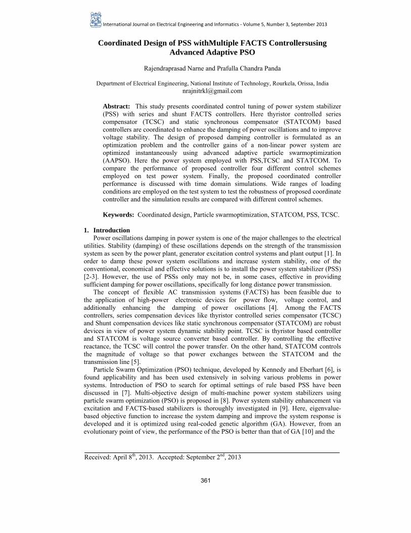
authors claimed that PSO arrives at its final parameter values in fewer generations than the GA. Moreover the authors tested several stabilizers like PSS, SVC, TCSC and TCPS individually to enhance system stability. In literature several researchers proposes the coordination of PSS with FATCS controllers to enhance dynamic performance of the power system. In [11], the authors discussed global tuning procedure for PSS and FACTS devices using a parameter-constrained nonlinear optimization algorithm. A robust coordinated design of a PSS and TCSCbased stabilizer is thoroughly investigated in [12], here an eigenvalue-based objective function is optimized using GA. In [13] the authors develop a novel algorithm for simultaneous coordinated designing of PSS and TCSC based controllers using bacterial swarm optimization. In [14], a multivariable design method has been performed on coordination between internal AC and DC voltage controllers. The coordination between the AC and DC voltage PI controllers was taken into consideration. A combination of a relay-switched shunt capacitor and a voltage-sourced inverter based static synchronous compensator to enhance dynamic compensation capability is discussed in [15]. In spite of this, eigenvalue-based control coordination design for achieving optimal damping of the electromechanical oscillations is discussed [16-17]. The present work deals with simultaneous coordinate tuning of PSS, TCSC and STATCOM based controllers. The TCSC damping controller improves the transient stability and STATCOM damping controller improves the voltage stability of the system. Hence, the combination of these controllers can enhance the overall stability of power system. Here, the control parameters of coordinate controller are optimized by minimizing objective function using AAPSO. The proposed controllers are tested individually as well as simultaneously with time-domain simulations. The robustness of the proposed controllers to enhance the power system dynamic performance is tested under different loading conditions. 2. Modelling of Power System with PSS A. Synchronous Machine Modelling The SMIB system equipped with PSS for generator excitation and FACTS based damping controllers are installed at generator terminals shown in Figure1. The coordinated controller shown in Figure 1 gives the control signals to all three stabilizers. The generator is modeled in third order model [2], which consists of electromechanical swing equation, and q-axis generator internal voltage equation. The dynamic equations are shown equations (1)-(3).
Figure 1. PSS and FACTS stabilizers connected to SMIB system
0)( ωωδ −=•
t (1)
fdE PQ
tVTX bV1LX
2LXI
TI
sI
sV
ControllerVoltageAC
ControllerVoltageD
C
∑
∑
SVΔ
DCVΔ
DCV
DCC
sX
mV
smαSTATCOM
busInfinite TCSC
TCSCX
Controllerdamping
dCoordinate
Rajendraprasad Narne, et al.
362
[ ] [ ])(2
)(2
00 tPP
Ht
HD
em −+−−=• ω
ωωω
(2)
[ ])()( )()(1 ''10
' tEtIXXtET
E qdddfdd
q −−−=•
(3)
Figure 2. IEEE Type-ST1 excitation system with a PSS
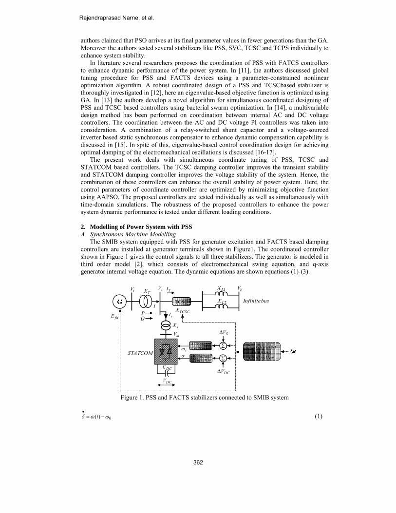
B. Exciter System Modelling Here, The IEEE Type-ST1 excitation system is considered which is shown in Figure 2. It represents a bus-fed thyristor excitation system (classified as type STIA1) with an automatic voltage regulator (AVR) and a power system stabilizer (PSS). The dynamic equation is given [2] by:
[ ]fdPSStrefA
Afd EUVVK
TE −+−=•
][1
(4)
3. Modelling of FACTS Controllers A. TCSC Based Damping Stabilizer The design structure of TCSC controller is based on conventional lead-lag structure. The input signal to the controller is speed deviation of the generator. The controller block consists of a gain block, washout block and two stage lead-lag blocks. The controller structure of TCSC is shown in Figure (3). In the controller wash out block act as high pass filter. The phase compensation block is to provide the necessary phase – lead characteristics to compensate for any phase lag between the input and the output signals. The dynamic equation for reactance of TCSC is given by
[ ]TCSCTCSCTCSCrefT
TTCSC XUXK
TX −−=
•)(1
(5)
B. STATCOM Based Damping Stabilizers As shown in Figure 1 the STATCOM is installed at generator terminals of SMIB system which is connected through a transformer with leakage reactance XS. The STATCOM consists of a 3-phase voltage source converter (VSC) and a DC capacitor whose capacitance is CDC. The VSC converts DC voltage VDC to a controllable AC voltage Vm at an angle αS. Voltage difference between these two voltages will provide path for power exchange between STATCOM and the power system. Hence we can maintain power flow by adjusting the voltage magnitude Vm and the phase angle αS. From Figure 1 we have [18]
SDCSSDCm kmVjkmVV ααα ∠=+= )sin(cos
(6)
)sincos( SSqSSd
DCDC II
CkmV αα +=
•
(7)
w
wsT
sT+1 PSSK ωΔ
reftV
PSSU
tV
fdE∑
minfdE
maxfdE
minPSSU
maxPSSU
+
+ A
AsT
K+1
)1)(1()1)(1(
42
31
pp
pp
sTsTsTsT
++
++
Coordinated Design of PSS withMultiple FACTS
363
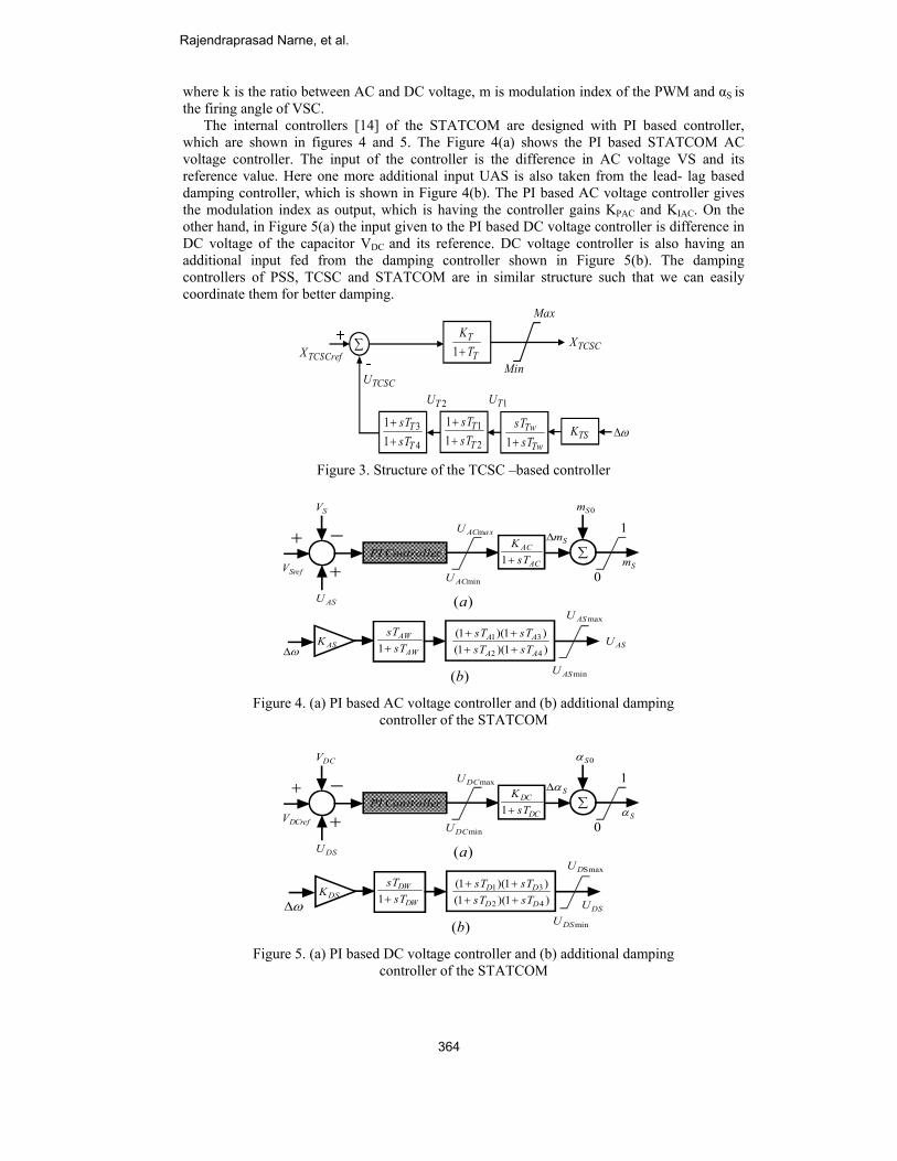
where k is the ratio between AC and DC voltage, m is modulation index of the PWM and αS is the firing angle of VSC. The internal controllers [14] of the STATCOM are designed with PI based controller, which are shown in figures 4 and 5. The Figure 4(a) shows the PI based STATCOM AC voltage controller. The input of the controller is the difference in AC voltage VS and its reference value. Here one more additional input UAS is also taken from the lead- lag based damping controller, which is shown in Figure 4(b). The PI based AC voltage controller gives the modulation index as output, which is having the controller gains KPAC and KIAC. On the other hand, in Figure 5(a) the input given to the PI based DC voltage controller is difference in DC voltage of the capacitor VDC and its reference. DC voltage controller is also having an additional input fed from the damping controller shown in Figure 5(b). The damping controllers of PSS, TCSC and STATCOM are in similar structure such that we can easily coordinate them for better damping.
Figure 3. Structure of the TCSC –based controller
Figure 4. (a) PI based AC voltage controller and (b) additional damping
controller of the STATCOM
Figure 5. (a) PI based DC voltage controller and (b) additional damping
controller of the STATCOM
ωΔ
TCSCU
TCSCX∑
1TU
T
TT
K+1
2TU
Min
Max
2
111
T
TsTsT
++
4
311
T
TsTsT
++
Tw
TwsT
sT+1 TSK
TCSCrefX
ControllerPISrefV
SV
ASU
+ −
+
SmΔ
0Sm
∑
0
1
Sm
ASKAW
AW
sTsT+1 )1)(1(
)1)(1(
42
31
AA
AA
sTsTsTsT
++++
ωΔASU
minASU
maxASU
minACU
axACU m
)(a
)(b
AC
AC
sTK+1
ControllerPIDCrefV
DCV
DSU
+ −
+
SαΔ
0Sα
∑
0
1
Sα
DSKDW
DW
sTsT+1 )1)(1(
)1)(1(
42
31
DD
DD
sTsTsTsT
++++
ωΔ DSU
minDSU
SmaxDU
minDCU
maxDCU
)(a
)(b
DC
DC
sTK+1
Rajendraprasad Narne, et al.
364
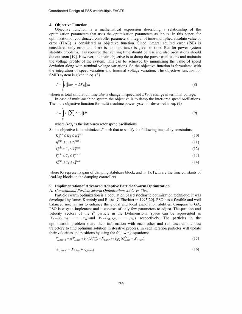
4. Objective Function Objective function is a mathematical expression describing a relationship of the optimization parameters that uses the optimization parameters as inputs. In this paper, for optimization of coordinated controller parameters, integral of time-multiplied absolute value of error (ITAE) is considered as objective function. Since integral squired error (ISE) is considered only error and there is no importance is given to time. But for power system stability problems, it is required that settling time should be less and also oscillations should die out soon [19]. However, the main objective is to damp the power oscillations and maintain the voltage profile of the system. This can be achieved by minimizing the value of speed deviation along with terminal voltage variations. So the objective function is formulated with the integration of speed variation and terminal voltage variation. The objective function for SMIB system is given in eq. (8)
∫ Δ+Δ=t
Tii dtVtJ0
][ ω (8)
wheret is total simulation time, Δω is change in speed,and ΔVT is change in terminal voltage. In case of multi-machine system the objective is to damp the inter-area speed oscillations. Then, the objective function for multi-machine power system is described in eq. (9)
∫ ∑ Δ=t
I dttJ0
][ ω (9)
where IωΔ is the inter-area rotor speed oscillations So the objective is to minimize ‘J’ such that to satisfy the following inequality constraints,
maxminSSS KKK ≤≤ (10)
max
11min
1 TTT ≤≤ (11)
max
22min
2 TTT ≤≤ (12)
max
33min
3 TTT ≤≤ (13)
max
44min
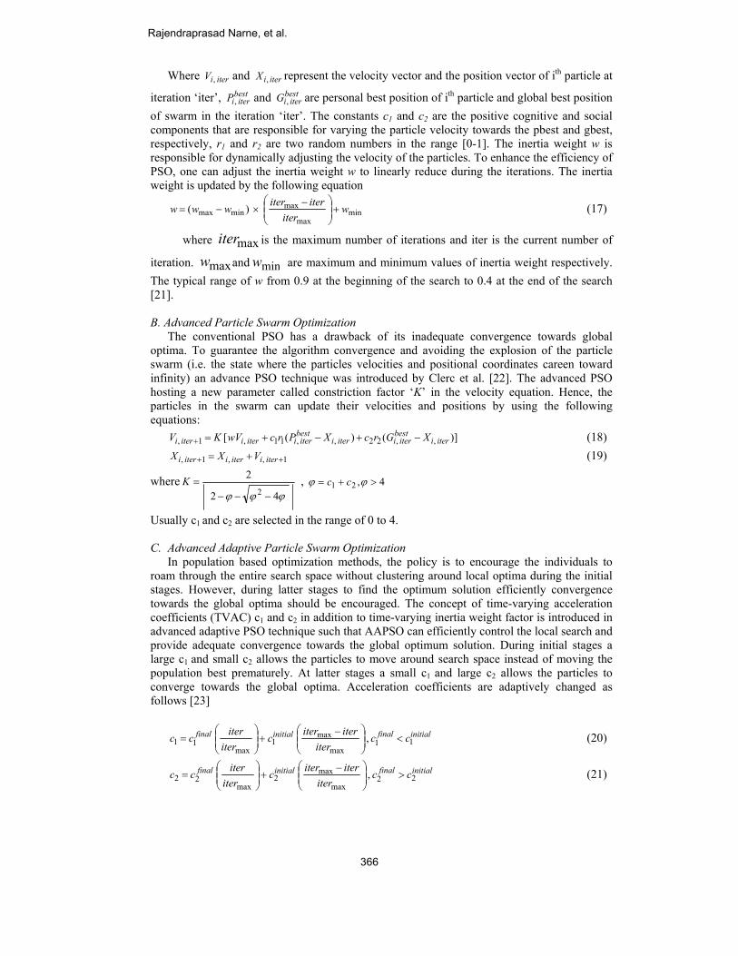
4 TTT ≤≤ (14) where KS represents gain of damping stabilizer block, and T1,T2,T3,T4 are the time constants of lead-lag blocks in the damping controllers. 5. Implimentationof Advanced Adaptive Particle Swarm Optimization A. Conventional Particle Swarm Optimization: An Over View Particle swarm optimization is a population based stochastic optimization technique. It was developed by James Kennedy and Russel C Eberhart in 1995[20]. PSO has a flexible and well balanced mechanism to enhance the global and local exploration abilities. Compare to GA, PSO is easy to implement and it consists of only few parameters to adjust. The position and velocity vectors of the ith particle in the D-dimensional space can be represented as
) ...,.......... , ,( 21 idiii xxxX = and ) ...,.......... , ,( 21 idiii vvvV = respectively. The particles in the optimization problem share their information with each other and run towards the best trajectory to find optimum solution in iterative process. In each iteration particles will update their velocities and positions by using the following equations: )( )( , ,22 , ,11 ,1 , iteri
bestiteriiteri
bestiteriiteriiteri XGrcXPrcwVV −+−+=+ (15)
1 , ,1 , ++ += iteriiteriiteri VXX (16)
Coordinated Design of PSS withMultiple FACTS
365
Where iteriV , and iteriX , represent the velocity vector and the position vector of ith particle at
iteration ‘iter’, bestiteriP , and best
iteriG , are personal best position of ith particle and global best position of swarm in the iteration ‘iter’. The constants c1 and c2 are the positive cognitive and social components that are responsible for varying the particle velocity towards the pbest and gbest, respectively, r1 and r2 are two random numbers in the range [0-1]. The inertia weight w is responsible for dynamically adjusting the velocity of the particles. To enhance the efficiency of PSO, one can adjust the inertia weight w to linearly reduce during the iterations. The inertia weight is updated by the following equation
minmax
maxminmax )( w
iteriteriterwww +⎟⎟
⎠
⎞⎜⎜⎝
⎛ −×−=
(17)
where maxiter is the maximum number of iterations and iter is the current number of
iteration. maxw and minw are maximum and minimum values of inertia weight respectively. The typical range of w from 0.9 at the beginning of the search to 0.4 at the end of the search [21].
B. Advanced Particle Swarm Optimization The conventional PSO has a drawback of its inadequate convergence towards global optima. To guarantee the algorithm convergence and avoiding the explosion of the particle swarm (i.e. the state where the particles velocities and positional coordinates careen toward infinity) an advance PSO technique was introduced by Clerc et al. [22]. The advanced PSO hosting a new parameter called constriction factor ‘K’ in the velocity equation. Hence, the particles in the swarm can update their velocities and positions by using the following equations: )]()([ , ,22 , ,11 ,1 , iteri
bestiteriiteri
bestiteriiteriiteri XGrcXPrcwVKV −+−+=+ (18)
1 , ,1 , ++ += iteriiteriiteri VXX (19)
where 42
22 ϕϕϕ −−−
=K , 4,21 >+= ϕϕ cc
Usually c1 and c2 are selected in the range of 0 to 4. C. Advanced Adaptive Particle Swarm Optimization In population based optimization methods, the policy is to encourage the individuals to roam through the entire search space without clustering around local optima during the initial stages. However, during latter stages to find the optimum solution efficiently convergence towards the global optima should be encouraged. The concept of time-varying acceleration coefficients (TVAC) c1 and c2 in addition to time-varying inertia weight factor is introduced in advanced adaptive PSO technique such that AAPSO can efficiently control the local search and provide adequate convergence towards the global optimum solution. During initial stages a large c1 and small c2 allows the particles to move around search space instead of moving the population best prematurely. At latter stages a small c1 and large c2 allows the particles to converge towards the global optima. Acceleration coefficients are adaptively changed as follows [23]
initialfinalinitialfinal cciter
iteriterciter
itercc 11max
max1
max11 , <⎟⎟
⎠
⎞⎜⎜⎝
⎛ −+⎟⎟
⎠
⎞⎜⎜⎝
⎛= (20)
initialfinalinitialfinal cciter
iteriterciter
itercc 22max
max2
max22 , >⎟⎟
⎠
⎞⎜⎜⎝
⎛ −+⎟⎟
⎠
⎞⎜⎜⎝
⎛= (21)
Rajendraprasad Narne, et al.
366

Where initialinitial cc 21 , and finalfinal cc 21 , are initial and final values of the acceleration coefficients c1 and c2 respectively. In this work, PSO is used for optimizing the control variables of PSS and STATCOM as well as TCSC based controllers. The simultaneous tuning procedure using PSO is given in the form of flow chat shown in Figure 6. Here, all control parameters of damping controllers are optimized by minimizing the objective function given in equation (8 or 9). The ranges of optimal parameter are [0.01 – 50] for Ks, and [0.05 – 1] for T1and T3. However, for lead T-compensation the range of time constants T2, T4 should be less than T1, T3 so the range taken as [0.001-0.04] for T2 and T4. The washout time Tw is set as 5.
Figure 6. Flow diagram of AAPSO algorithm for proposed coordinated design
6. Simulation Results A. Test system 1: Single machine infinite bus system The dynamic performance of the test system is analyzed under different loading conditions. The non-linear model simulation is carried out using MATLAB programming for a three phase fault. The fault is applied to the one of the transmission line nearer to the generator terminals. Here, fault applied at 1 sec. and cleared at 1.1sec (i.e. a six cycle fault is applied to the system). The final optimized parameter values of coordinated damping controller are given in Table 1. The following different loadings or changes applied on test system to test the robustness of proposed coordinate controller.
Table 1. Optimal parameter settings of the proposed coordinated controller Control
parameters PSS TCSC STATCOM ACVC
STATCOM DCVC
KS 15.562 12.224 11.239 17.989 T1 0.541 0.966 0.659 0.854 T2 0.023 0.034 0.015 0.026 T3 0.362 0.814 0.647 0.729 T4 0.032 0.019 0.022 0.021
Case I: Nominal loading condition (i.e.Pe=1.0p.u. and Qe=0.25p.u.) The MATLAB simulations results are compared in Figure 7 under nominal loading condition. In the figure (a), (b), (c), and (d) indicate the rotor angle variation, rotor speed variation, active power variation, and terminal voltage variations respectively. From the Figure
Coordinated Design of PSS withMultiple FACTS
367
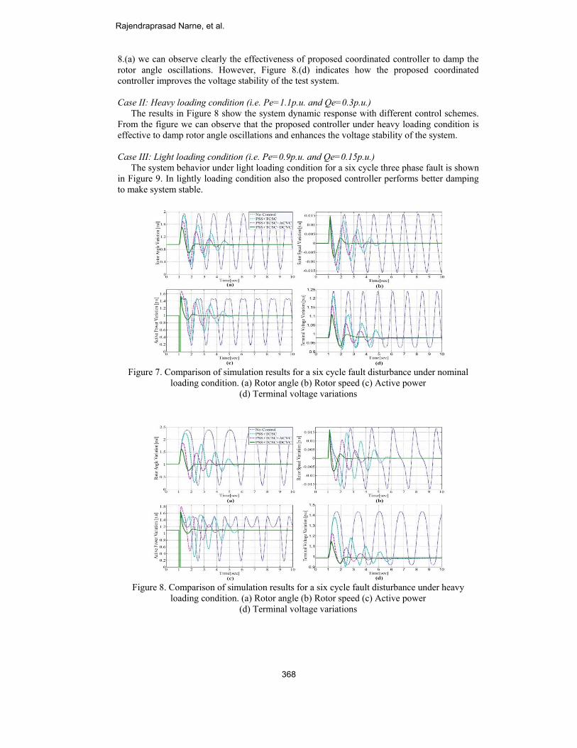
8.(a) we can observe clearly the effectiveness of proposed coordinated controller to damp the rotor angle oscillations. However, Figure 8.(d) indicates how the proposed coordinated controller improves the voltage stability of the test system. Case II: Heavy loading condition (i.e. Pe=1.1p.u. and Qe=0.3p.u.) The results in Figure 8 show the system dynamic response with different control schemes. From the figure we can observe that the proposed controller under heavy loading condition is effective to damp rotor angle oscillations and enhances the voltage stability of the system. Case III: Light loading condition (i.e. Pe=0.9p.u. and Qe=0.15p.u.) The system behavior under light loading condition for a six cycle three phase fault is shown in Figure 9. In lightly loading condition also the proposed controller performs better damping to make system stable.
Figure 7. Comparison of simulation results for a six cycle fault disturbance under nominal
loading condition. (a) Rotor angle (b) Rotor speed (c) Active power (d) Terminal voltage variations
Figure 8. Comparison of simulation results for a six cycle fault disturbance under heavy
loading condition. (a) Rotor angle (b) Rotor speed (c) Active power (d) Terminal voltage variations
Rajendraprasad Narne, et al.
368
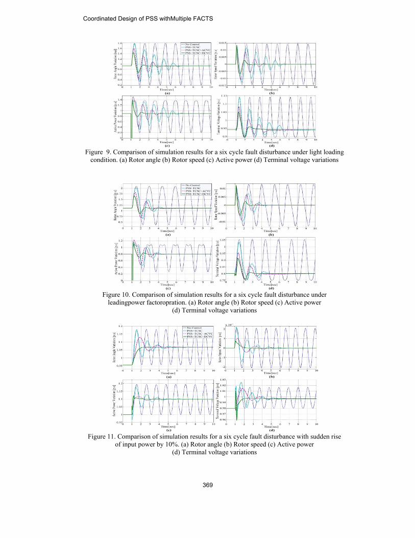
Figure 9. Comparison of simulation results for a six cycle fault disturbance under light loading
condition. (a) Rotor angle (b) Rotor speed (c) Active power (d) Terminal voltage variations
Figure 10. Comparison of simulation results for a six cycle fault disturbance under
leadingpower factoropration. (a) Rotor angle (b) Rotor speed (c) Active power (d) Terminal voltage variations
Figure 11. Comparison of simulation results for a six cycle fault disturbance with sudden rise
of input power by 10%. (a) Rotor angle (b) Rotor speed (c) Active power (d) Terminal voltage variations
Coordinated Design of PSS withMultiple FACTS
369
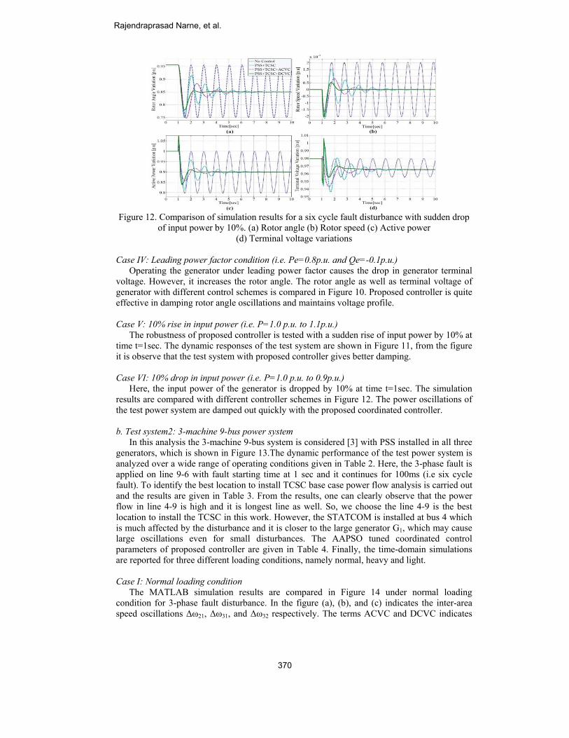
Figure 12. Comparison of simulation results for a six cycle fault disturbance with sudden drop
of input power by 10%. (a) Rotor angle (b) Rotor speed (c) Active power (d) Terminal voltage variations
Case IV: Leading power factor condition (i.e. Pe=0.8p.u. and Qe=-0.1p.u.) Operating the generator under leading power factor causes the drop in generator terminal voltage. However, it increases the rotor angle. The rotor angle as well as terminal voltage of generator with different control schemes is compared in Figure 10. Proposed controller is quite effective in damping rotor angle oscillations and maintains voltage profile. Case V: 10% rise in input power (i.e. P=1.0 p.u. to 1.1p.u.) The robustness of proposed controller is tested with a sudden rise of input power by 10% at time t=1sec. The dynamic responses of the test system are shown in Figure 11, from the figure it is observe that the test system with proposed controller gives better damping. Case VI: 10% drop in input power (i.e. P=1.0 p.u. to 0.9p.u.) Here, the input power of the generator is dropped by 10% at time t=1sec. The simulation results are compared with different controller schemes in Figure 12. The power oscillations of the test power system are damped out quickly with the proposed coordinated controller. b. Test system2: 3-machine 9-bus power system In this analysis the 3-machine 9-bus system is considered [3] with PSS installed in all three generators, which is shown in Figure 13.The dynamic performance of the test power system is analyzed over a wide range of operating conditions given in Table 2. Here, the 3-phase fault is applied on line 9-6 with fault starting time at 1 sec and it continues for 100ms (i.e six cycle fault). To identify the best location to install TCSC base case power flow analysis is carried out and the results are given in Table 3. From the results, one can clearly observe that the power flow in line 4-9 is high and it is longest line as well. So, we choose the line 4-9 is the best location to install the TCSC in this work. However, the STATCOM is installed at bus 4 which is much affected by the disturbance and it is closer to the large generator G1, which may cause large oscillations even for small disturbances. The AAPSO tuned coordinated control parameters of proposed controller are given in Table 4. Finally, the time-domain simulations are reported for three different loading conditions, namely normal, heavy and light. Case I: Normal loading condition The MATLAB simulation results are compared in Figure 14 under normal loading condition for 3-phase fault disturbance. In the figure (a), (b), and (c) indicates the inter-area speed oscillations Δω21, Δω31, and Δω32 respectively. The terms ACVC and DCVC indicates
Rajendraprasad Narne, et al.
370
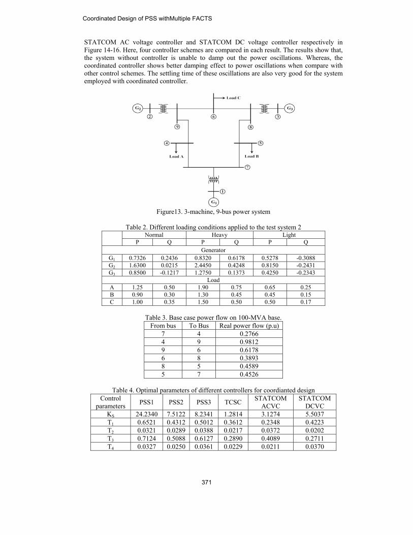
STATCOM AC voltage controller and STATCOM DC voltage controller respectively in Figure 14-16. Here, four controller schemes are compared in each result. The results show that, the system without controller is unable to damp out the power oscillations. Whereas, the coordinated controller shows better damping effect to power oscillations when compare with other control schemes. The settling time of these oscillations are also very good for the system employed with coordinated controller.
Figure13. 3-machine, 9-bus power system
Table 2. Different loading conditions applied to the test system 2
Normal Heavy Light P Q P Q P Q
Generator G1 0.7326 0.2436 0.8320 0.6178 0.5278 -0.3088 G2 1.6300 0.0215 2.4450 0.4248 0.8150 -0.2431 G3 0.8500 -0.1217 1.2750 0.1373 0.4250 -0.2343
Load A 1.25 0.50 1.90 0.75 0.65 0.25 B 0.90 0.30 1.30 0.45 0.45 0.15 C 1.00 0.35 1.50 0.50 0.50 0.17
Table 3. Base case power flow on 100-MVA base.
From bus To Bus Real power flow (p.u) 7 4 0.2766 4 9 0.9812 9 6 0.6178 6 8 0.3893 8 5 0.4589 5 7 0.4526
Table 4. Optimal parameters of different controllers for coordianted design
Control parameters PSS1 PSS2 PSS3 TCSC STATCOM
ACVC STATCOM
DCVC KS 24.2340 7.5122 8.2341 1.2814 3.1274 5.5037 T1 0.6521 0.4312 0.5012 0.3612 0.2348 0.4223 T2 0.0321 0.0289 0.0388 0.0217 0.0372 0.0202 T3 0.7124 0.5088 0.6127 0.2890 0.4089 0.2711 T4 0.0327 0.0250 0.0361 0.0229 0.0211 0.0370
Coordinated Design of PSS withMultiple FACTS
371
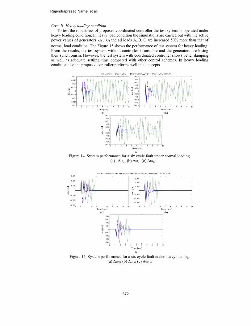
Case II: Heavy loading condition To test the robustness of proposed coordinated controller the test system is operated under heavy loading condition. In heavy load condition the simulations are carried out with the active power values of generators 2G , 3G and all loads A, B, C are increased 50% more than that of normal load condition. The Figure 15 shows the performance of test system for heavy loading. From the results, the test system without controller is unstable and the generators are losing their synchronism. However, the test system with coordinated controller shows better damping as well as adequate settling time compared with other control schemes. In heavy loading condition also the proposed controller performs well in all accepts.
Figure 14. System performance for a six cycle fault under normal loading.
(a) Δω21 (b) Δω31 (c) Δω23.
Figure 15. System performance for a six cycle fault under heavy loading.
(a) Δω21 (b) Δω31 (c) Δω23.
Rajendraprasad Narne, et al.
372
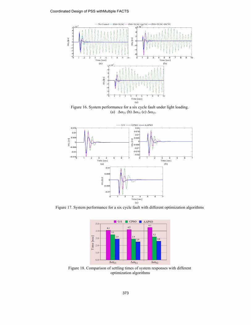
Figure 16. System performance for a six cycle fault under light loading.
(a) Δω21 (b) Δω31 (c) Δω23.
Figure 17. System performance for a six cycle fault with different optimization algorithms
Figure 18. Comparison of settling times of system responses with different
optimization algorithms
Coordinated Design of PSS withMultiple FACTS
373
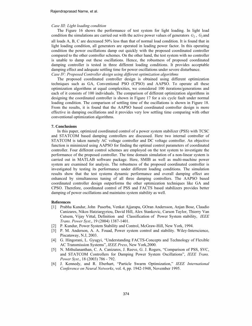
Case III: Light loading condition The Figure 16 shows the performance of test system for light loading. In light load condition the simulations are carried out with the active power values of generators 2G , 3G and all loads A, B, C are decreased 50% less than that of normal load condition. It is found that in light loading condition, all generators are operated in leading power factor. In this operating condition the power oscillations damp out quickly with the proposed coordinated controller compared to the other controller schemes. On the other hand, the test system with no controller is unable to damp out these oscillations. Hence, the robustness of proposed coordinated damping controller is tested in three different loading conditions. It provides acceptable damping effect and adequate settling time for power oscillations under severe disturbance. Case IV: Proposed Controller design using different optimization algorithms The proposed coordinated controller design is obtained using different optimization techniques such as GA, Conventional PSO (CPSO) and AAPSO. To operate all these optimization algorithms at equal complexities, we considered 100 iterations/generations and each of it consists of 100 individuals. The comparison of different optimization algorithms in designing the coordinated controller is shown in Figure 17 for a six cycle fault under normal loading condition. The comparison of settling time of the oscillations is shown in Figure 18. From the results, it is found that the AAPSO based coordinated controller design is more effective in damping oscillations and it provides very low settling time comparing with other conventional optimization algorithms. 7. Conclusions In this paper, optimized coordinated control of a power system stabilizer (PSS) with TCSC and STATCOM based damping controllers are discussed. Here two internal controller of STATCOM is taken namely AC voltage controller and DC voltage controller. An objective function is minimized using AAPSO for finding the optimal control parameters of coordinated controller. Four different control schemes are employed on the test system to investigate the performance of the proposed controller. The time domain simulation of a non-linear system is carried out in MATLAB software package. Here, SMIB as well as multi-machine power system are examined for analysis. The robustness of the proposed coordinated controller is investigated by testing its performance under different loading conditions. The simulation results show that the test systems dynamic performance and overall damping effect are enhanced by simultaneous tuning of all three damping controllers. The AAPSO based coordinated controller design outperforms the other optimization techniques like GA and CPSO. Therefore, coordinated control of PSS and FACTS based stabilizers provides better damping of power oscillations and maintains system stability as well. References [1] Prabha Kundur, John Paserba, Venkat Ajjarapu, GOran Andersson, Anjan Bose, Claudio
Canizares, Nikos Hatziargyriou, David Hill, Alex Stankovic, Carson Taylor, Thierry Van Cutsem, Vijay Vittal, Definition and Classification of Power System stability, IEEE Trans. Power Syst., 19 (2004) 1387-1401.
[2] P. Kundur, Power System Stability and Control, McGraw-Hill, New York, 1994. [3] P. M. Anderson, A. A. Fouad, Power system control and stability. Wiley-Interscience,
Piscataway, N.J, 2003. [4] G. Hingorani, L. Gyugyi, “Understanding FACTS-Concepts and Technology of Flexible
AC Transmission Systems”, IEEE Press, New York,2000. [5] N. Mithulananthan, C. A. Canizares, J. Reeve, G. J. Rogers, “Comparison of PSS, SVC,
and STATCOM Controllers for Damping Power System Oscillations”, IEEE Trans. Power Syst., 18 (2003) 786 - 792.
[6] J. Kennedy, and R. Eberhart, “Particle Swarm Optimization,” IEEE International Conference on Neural Networks, vol. 4, pp. 1942-1948, November 1995.
Rajendraprasad Narne, et al.
374
[7] M. A. Abido, “Optimal Design of Power–System Stabilizers Using Particle Swarm Optimization” IEEE Trans. Energy Conv., vol. 17, no. 3, pp. 406-413, September 2002.
[8] H. Shayeghi, H.A. Shayanfar, A. Safari, and R. Aghmasheh, “A robust PSSs design using PSO in a multi-machine environment” Energy Convers Manage, vol. 51, pp. 696–702, 2010.
[9] M. A. Abido, “Analysis of Power System Stability Enhancement via Excitation and Facts-Based Stabilizers” Elect. Power Compon and Syst., vol. 32, no. 1, pp. 75-91, 2004.
[10] Sidhartha Panda, and Narayana Prasad Padhy, “Comparison of particle swarm optimization and genetic algorithm for FACTS-based controller design” Applied Soft Computing, vol. 8, pp. 1418–1427, 2008.
[11] Xianzhang Lei, Edwin N. Lerch, Dusan Povh, “Optimization and Coordination of Damping Controls for Improving System Dynamic Performance”, IEEE Trans. Power Syst., 16 (2001) 473-480.
[12] Y.L. Abdel-Magid, M.A. Abido, Robust coordinated design of excitation and TCSC-based stabilizers using genetic algorithms, Electric Power Syst. Res., 69 (2004) 129–141.
[13] E.S. Ali, S.M. Abd-Elazim, “Coordinated design of PSSs and TCSC via bacterial swarm optimization algorithm in a multimachine power system”, Int. J. Elect. Power and Energy Syst., 36 (2012) 84–92.
[14] H.F.Wang, Interactions, ‘Multivariable Design of STATCOM AC and DC Voltage Control”, Int. J. Elect. Power and Energy Syst., 25 (2003) 387-394.
[15] W. L. Chen, Y. G. Huang, C. H. Pien, “Control and Performance Analysis for a Capacitor-coordinated Static Synchronous Compensator to Enhance Dynamic Compensation Capability”, Elect. Power Compon. and Syst., 39 (2011) 991-1006.
[16] T.T. Nguyen, R. Gianto, “Optimal design for control coordination of power system stabilisers and flexible alternating current transmission system devices with controller saturation limits”, IET Gener. Transm. Distrib., 4 (2010) 1028 – 1043.
[17] M. Aliakbar Golkar, M. Zarringhalami, “Coordinated Design of PSS and STATCOM Parameters for Power System Stability Improvement Using Genetic Algorithm”, Iranian J. of Elect.and Computer Engg., 8 (2009) 80-88.
[18] H. F. Wang, “Phillips-Heffron model of power systems installed with STATCOM and applications”, IEE Proc-Gener. Transm. Distrib., 146 (1999) 521-527.
[19] Sidhartha Panda, “Differentital evolutionary algorithm for TCSC-based controller design”, Simulation Modelling Practice and Theory, 17 (2009) 1618-1634.
[20] K.T. Chaturvedi, M. Pandit, L. Srivastava. “Self-organizing hierarchical particle swarm optimization for non-convex economic dispatch”. IEEE Trans. Power Syst. 2008; 23(3):1079–1087.
[21] Yu-hui Shi, Russell C Eberhart. “Empirical study of particle swarm optimization”. in Proc. IEEE Int. Congr. Evolutionary Computation 1999; 3:101–106.
[22] M. Clerc, J. Kennedy. “The particle swarm - explosion, stability, and convergence in a multidimensional complex space”. IEEE Trans. Evolutionary Computation, 2002; 6:58–73.
[23] A. Ratnaweera, S.K. Halgamuge, H.C. Watson. “Self-organizing hierarchical particle swarm optimizer with time-varying acceleration coefficients”. IEEE Trans. Evol. Comput. 2004; 8(3):240–255.
Appendix A a). The SMIB system parameters: All the data are in per unit unless specified. Genarator : H = 8.0 MJ/MVA, D1 = 0.0, T’
d0 = 5.044 sec., f = 60 Hz Xd= 0.9, Xq= 0.6, X’
d= 0.3 Transformer : XT = 0.1, XS = 0.1 Transmission lines : XL1 = XL2 = 0.3
Coordinated Design of PSS withMultiple FACTS
375
b). System
21 =H'
2 =dX'02 =dT
Excite c). Optim Genet Conve
transmiss
m data for 3-m
,64.23 4.62 =H
0.1198,= '3 =dX
,00.6= .5'03 =dT
er: 21 == AA KK
mization parametic Algorithms
entional PSO
Rajen21 19EnginPowehe is Rourkresearcontro
Prafu1948. engine1974 Since OrissaFellowdynam
ion.
machine 9-bus p
,0 ,01.33 =H X
0.1813,= 1 =qX
89 ,023 =AK 1TA =
eters: : Selection o Mutation Pr Generations: C1= C2= 2.0
ndraprasad N985. He receineering from JNr System Engiworking towarkela, Orissa, Irch interests inollers.
ulla ChandraHe received
eering from Sand 1990 respe1977, he has
a, India, wherew of IE (India)mic stability
power system [
0.1460,1 =dX dX
0.0969, 02 =qX
0.032 TT AA ===
operator: Roulrobability = 0.0s.
0, w = 0.9, Term
Narne was borived his B.TeNTU Hyderabaineering from Ards his Ph.D. dIndia, under tnclude power
Panda (SM’0his B.Sc., M
Sambalpur Unectively. been with Na
e he is now a p). At present, hanalysis, FAC
[3]: all data in
0.8958,2 =d dX
0.8645, 13 =qX
.05s
ette Wheel, C01, Terminatio
mination Metho
rn in Andhra Pech. degree inad, India, in 20Anna Universidegree at Natiothe supervisiosystem stabili
05) was born M.Sc., and Ph.Dniversity, Oriss
ational Institutrofessor. He is
his research intCTS Controll
p.u. on a 100-M
1.3125,3 =d'dX
.2578, 8.'01 =dT
Crossover Probon Method: Ma
od: Maximum
Pradesh, India n Electrical an007, and the Mity, India in 20onal Institute oon of Prof. Pity and contro
in Orissa on ND. degrees, alsa, India, in th
te of Technolos senior membeterests include lers and Hig
MVA base
0.0608,'1 =d
.96,
bability = 0.8,aximum
iterations.
on Novembernd Electronics
M .E. Degree in009. Currently,of Technology,P.C.Panda. Hisl, and FACTS
November 01,ll in electricalhe year 1971,
ogy, Rourkela,er of IEEE andPower system
gh voltage dc
,
r s n , , s S
, l ,
, d
m c
Rajendraprasad Narne, et al.
376