Embed Size (px)
Citation preview
Copyright © 2005 Marconi Corporation plc. All rights reserved
Network Timing
ATM Switch
2 Copyright © 2005 Marconi Corporation plc. All rights reserved
Objectives
Explain the purpose of network synchronization Identify the meaning of the Stratum clocking grades Identify the internal and external timing components
associated with the CEC-Plus and ASX-4000 Series TCM Describe the basic distribution of timing architecture for line
timing and external timing sources Configure the IP interfaces on the CEC-Plus Configure and verify timing (external timing example) on the
CEC-Plus and the ASX-4000 Series TCM
3 Copyright © 2005 Marconi Corporation plc. All rights reserved
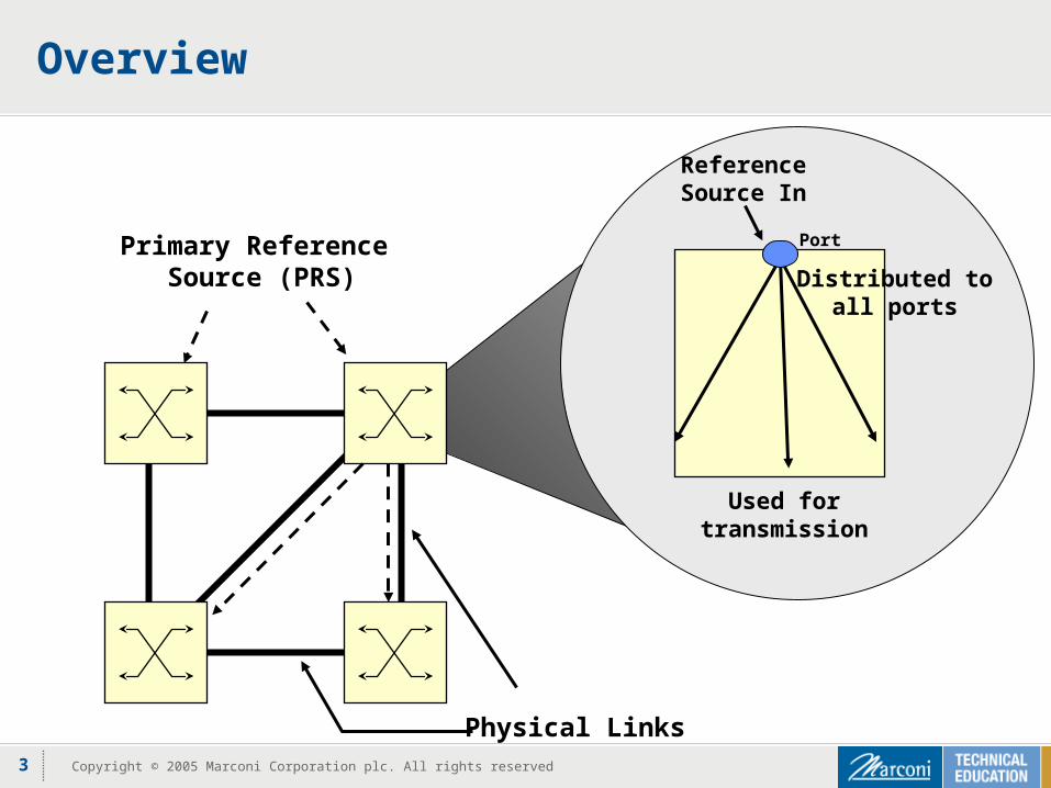
Overview
Physical Links
Primary Reference Source (PRS)
ReferenceSource In
Distributed toall ports
Used fortransmission
Port
4 Copyright © 2005 Marconi Corporation plc. All rights reserved
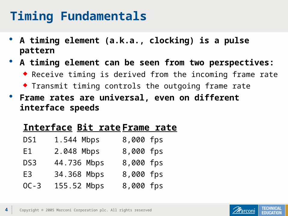
Timing Fundamentals
A timing element (a.k.a., clocking) is a pulse pattern A timing element can be seen from two perspectives:
Receive timing is derived from the incoming frame rate Transmit timing controls the outgoing frame rate
Frame rates are universal, even on different interface speeds
Interface Bit rate Frame rate
DS1 1.544 Mbps 8,000 fps
E1 2.048 Mbps 8,000 fps
DS3 44.736 Mbps 8,000 fps
E3 34.368 Mbps 8,000 fps
OC-3 155.52 Mbps 8,000 fps
5 Copyright © 2005 Marconi Corporation plc. All rights reserved
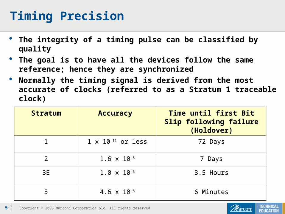
Timing Precision
The integrity of a timing pulse can be classified by quality The goal is to have all the devices follow the same reference;
hence they are synchronized Normally the timing signal is derived from the most accurate
of clocks (referred to as a Stratum 1 traceable clock)
Stratum Accuracy Time until first Bit Slip following failure (Holdover)
1 1 x 10-11 or less 72 Days
2 1.6 x 10⁻⁸ 7 Days
3E 1.0 x 10⁻⁶ 3.5 Hours
3 4.6 x 10⁻⁶ 6 Minutes
6 Copyright © 2005 Marconi Corporation plc. All rights reserved
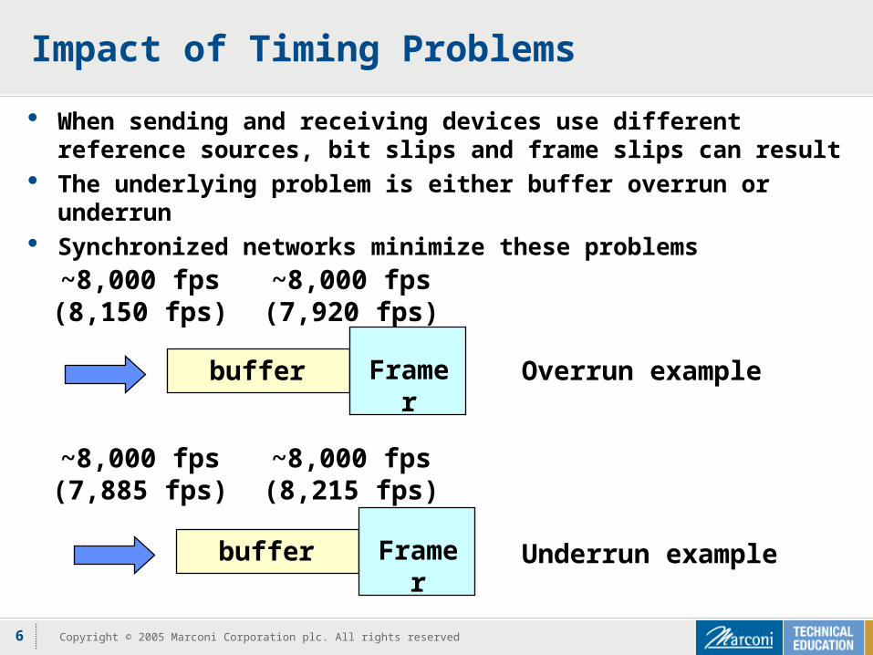
Impact of Timing Problems
When sending and receiving devices use different reference sources, bit slips and frame slips can result
The underlying problem is either buffer overrun or underrun Synchronized networks minimize these problems
buffer Framer
~8,000 fps(8,150 fps)
~8,000 fps(7,920 fps)
buffer Framer
~8,000 fps(7,885 fps)
~8,000 fps(8,215 fps)
Overrun example
Underrun example
7 Copyright © 2005 Marconi Corporation plc. All rights reserved
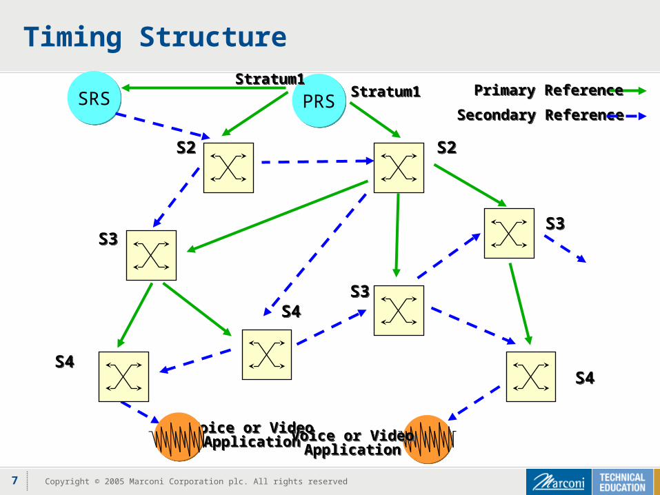
Timing Structure
PRSPRSSecondary ReferenceSecondary Reference
Primary ReferencePrimary ReferenceStratum1Stratum1
Stratum1Stratum1
S4S4S4S4
S3S3S3S3
S2S2 S2S2
S4S4S3S3
Voice or VideoApplication
Voice or VideoApplication Voice or Video
ApplicationVoice or Video
Application
SRSSRS
8 Copyright © 2005 Marconi Corporation plc. All rights reserved
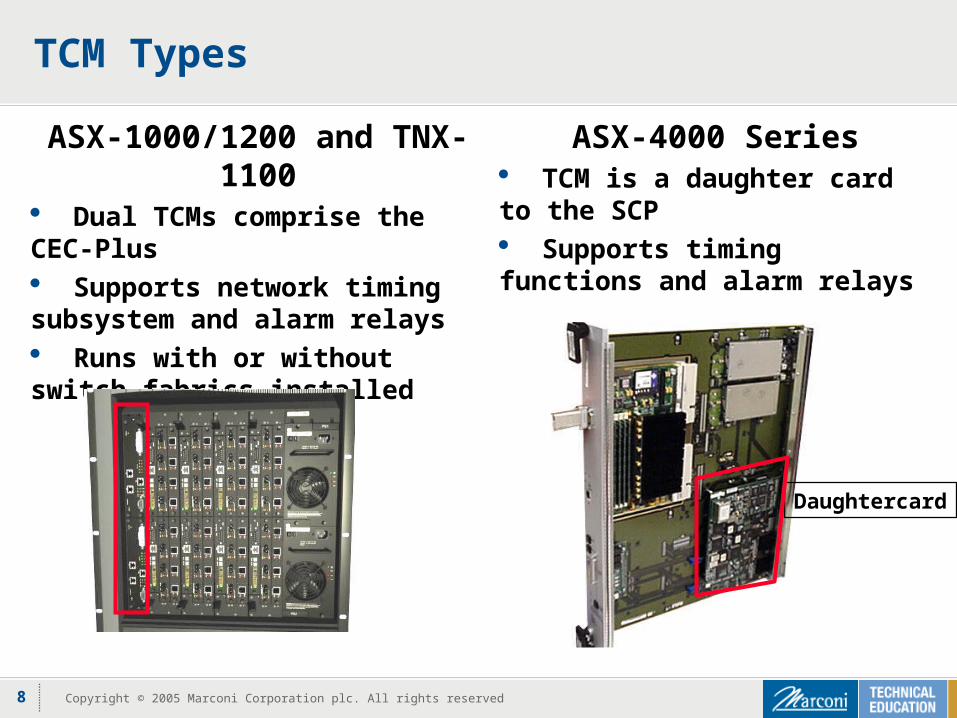
TCM Types
ASX-1000/1200 and TNX-1100 Dual TCMs comprise the CEC-Plus Supports network timing subsystem and alarm relays Runs with or without switch fabrics installed
ASX-4000 Series TCM is a daughter card to the SCP Supports timing functions and alarm relays
Daughtercard
9 Copyright © 2005 Marconi Corporation plc. All rights reserved
TCM Features
Hot-swappable ASX-4000 version is integral to SCP; must remove SCP
Redundant BITS inputs Line timing inputs
Hitless reference switching and failover Timing holdover Stratum 3 or 4 oscillator and digital phase lock loop Configurable alarm relay contacts
10 Copyright © 2005 Marconi Corporation plc. All rights reserved
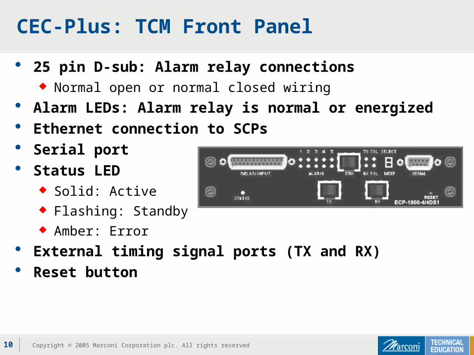
CEC-Plus: TCM Front Panel
25 pin D-sub: Alarm relay connections Normal open or normal closed wiring
Alarm LEDs: Alarm relay is normal or energized Ethernet connection to SCPs Serial port Status LED
Solid: Active Flashing: Standby Amber: Error
External timing signal ports (TX and RX) Reset button
11 Copyright © 2005 Marconi Corporation plc. All rights reserved
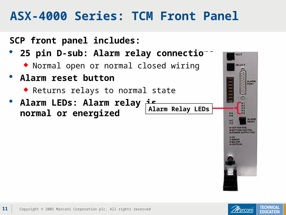
ASX-4000 Series: TCM Front Panel
SCP front panel includes: 25 pin D-sub: Alarm relay connections
Normal open or normal closed wiring Alarm reset button
Returns relays to normal state Alarm LEDs: Alarm relay is
normal or energized Alarm Relay LEDs
12 Copyright © 2005 Marconi Corporation plc. All rights reserved
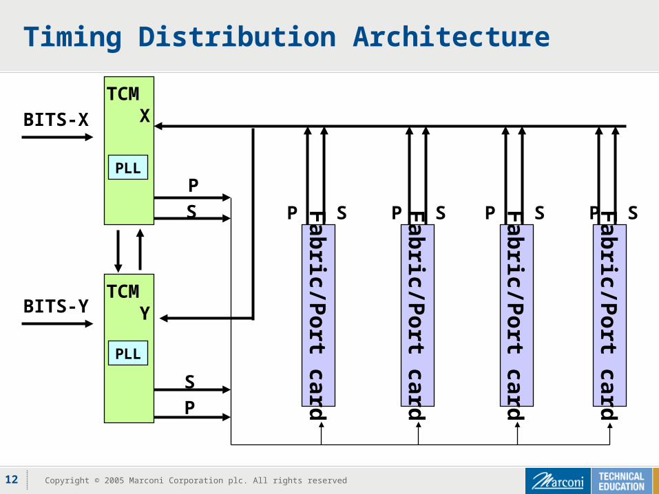
Timing Distribution Architecture
Fab
ric/Po
rt card
Fab
ric/Po
rt card
Fab
ric/Po
rt card
Fab
ric/Po
rt card
P P P SSSS P
S
S
P
P
BITS-Y
BITS-X
TCM X
TCM Y
PLL
PLL
13 Copyright © 2005 Marconi Corporation plc. All rights reserved
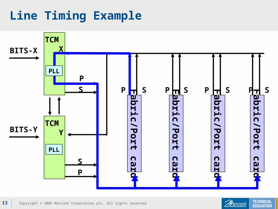
Line Timing Example
Fab
ric/Po
rt card
Fab
ric/Po
rt card
Fab
ric/Po
rt card
Fab
ric/Po
rt card
P P P SSSS P
S
S
P
P
BITS-Y
BITS-X
TCM X
TCM Y
PLL
PLL
14 Copyright © 2005 Marconi Corporation plc. All rights reserved
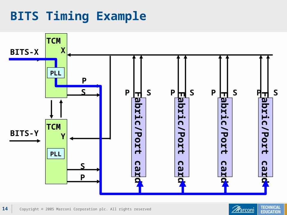
BITS Timing Example
Fab
ric/Po
rt card
Fab
ric/Po
rt card
Fab
ric/Po
rt card
Fab
ric/Po
rt card
P P P SSSS P
S
S
P
P
BITS-Y
BITS-X
TCM X
TCM Y
PLL
PLL
15 Copyright © 2005 Marconi Corporation plc. All rights reserved
Modes of Operation for TCM
Hitless modes move between available clock sources Line timing – references a network port
CEC-Plus: Automatic mode ASX-4000 Series: Line mode
BITS timing references an external source CEC-Plus: BITS mode ASX-4000 Series: External mode
Manual modes do not change sources FreeRun (internal oscillator) Primary (CEC-Plus only) Secondary (CEC-Plus only)
16 Copyright © 2005 Marconi Corporation plc. All rights reserved
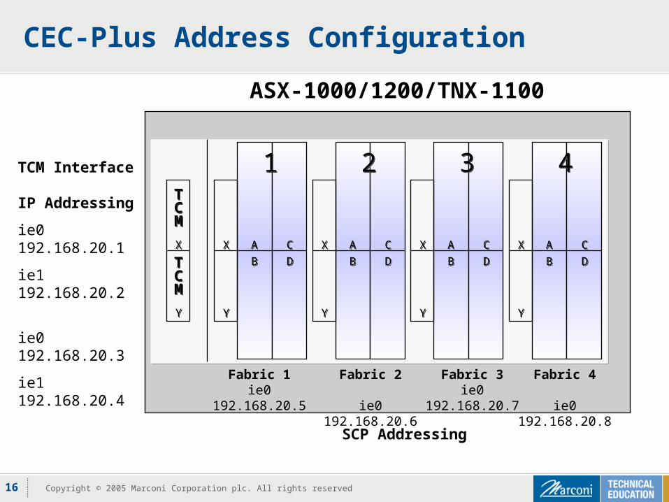
CEC-Plus Address Configuration
DDBB
CCAA
YY
XX
DDBB
CCAA
YY
XX
DDBB
CCAA
YY
XX
DDBB
CCAA
YY
XX
22 33 4411
YY
XX
TCM
TCM
TCM
TCM
TCM Interface IP Addressing
ie0 192.168.20.1
ie1 192.168.20.2
ie0 192.168.20.3
ie1 192.168.20.4
ASX-1000/1200/TNX-1100
Fabric 1ie0 192.168.20.5
SCP Addressing
Fabric 2
ie0 192.168.20.6
Fabric 3ie0 192.168.20.7
Fabric 4
ie0 192.168.20.8
17 Copyright © 2005 Marconi Corporation plc. All rights reserved
CEC-Plus Management Interface - EMI
Extended Management Interface (EMI) Used to configure the IP addresses for the TCM interfaces (ie0 and ie1)
ATM Management Interface (AMI) Controls the CEC-Plus after IP addresses are configured on the
Timing Control Modules (TCMs) The syntax used for EMI is different than AMI
18 Copyright © 2005 Marconi Corporation plc. All rights reserved
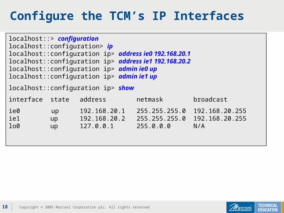
Configure the TCM’s IP Interfaces
localhost::> configurationlocalhost::configuration> iplocalhost::configuration ip> address ie0 192.168.20.1localhost::configuration ip> address ie1 192.168.20.2localhost::configuration ip> admin ie0 uplocalhost::configuration ip> admin ie1 up
localhost::configuration ip> show
interface state address netmask broadcast
ie0 up 192.168.20.1 255.255.255.0 192.168.20.255ie1 up 192.168.20.2 255.255.255.0 192.168.20.255lo0 up 127.0.0.1 255.0.0.0 N/A
19 Copyright © 2005 Marconi Corporation plc. All rights reserved
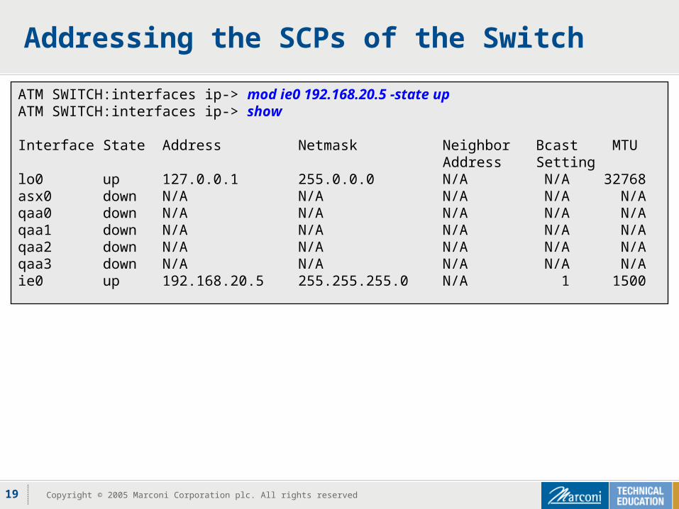
Addressing the SCPs of the Switch
ATM SWITCH:interfaces ip-> mod ie0 192.168.20.5 -state upATM SWITCH:interfaces ip-> show
Interface State Address Netmask Neighbor Bcast MTU Address Settinglo0 up 127.0.0.1 255.0.0.0 N/A N/A 32768asx0 down N/A N/A N/A N/A N/Aqaa0 down N/A N/A N/A N/A N/Aqaa1 down N/A N/A N/A N/A N/Aqaa2 down N/A N/A N/A N/A N/Aqaa3 down N/A N/A N/A N/A N/Aie0 up 192.168.20.5 255.255.255.0 N/A 1 1500
20 Copyright © 2005 Marconi Corporation plc. All rights reserved
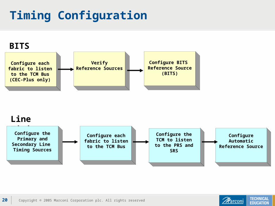
VerifyReference Sources
Timing Configuration
Configure each fabric to listen to the
TCM Bus
Configure the TCM to listen to the PRS
and SRS
Configure Automatic Reference Source
Line Timing
BITS
Configure BITS Reference Source
(BITS)
Configure each fabric to listen to the
TCM Bus(CEC-Plus only)
Configure the Primary and
Secondary Line Timing Sources
21 Copyright © 2005 Marconi Corporation plc. All rights reserved
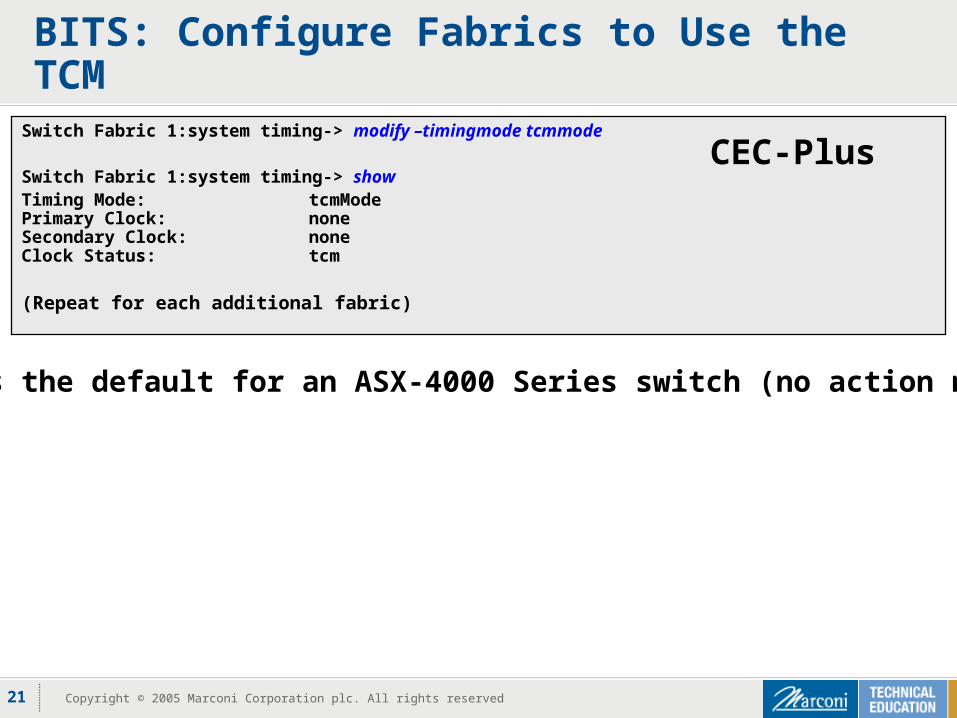
BITS: Configure Fabrics to Use the TCM
Switch Fabric 1:system timing-> modify –timingmode tcmmode
Switch Fabric 1:system timing-> showTiming Mode: tcmModePrimary Clock: noneSecondary Clock: noneClock Status: tcm
(Repeat for each additional fabric)
CEC-Plus
This is the default for an ASX-4000 Series switch (no action needed)
22 Copyright © 2005 Marconi Corporation plc. All rights reserved
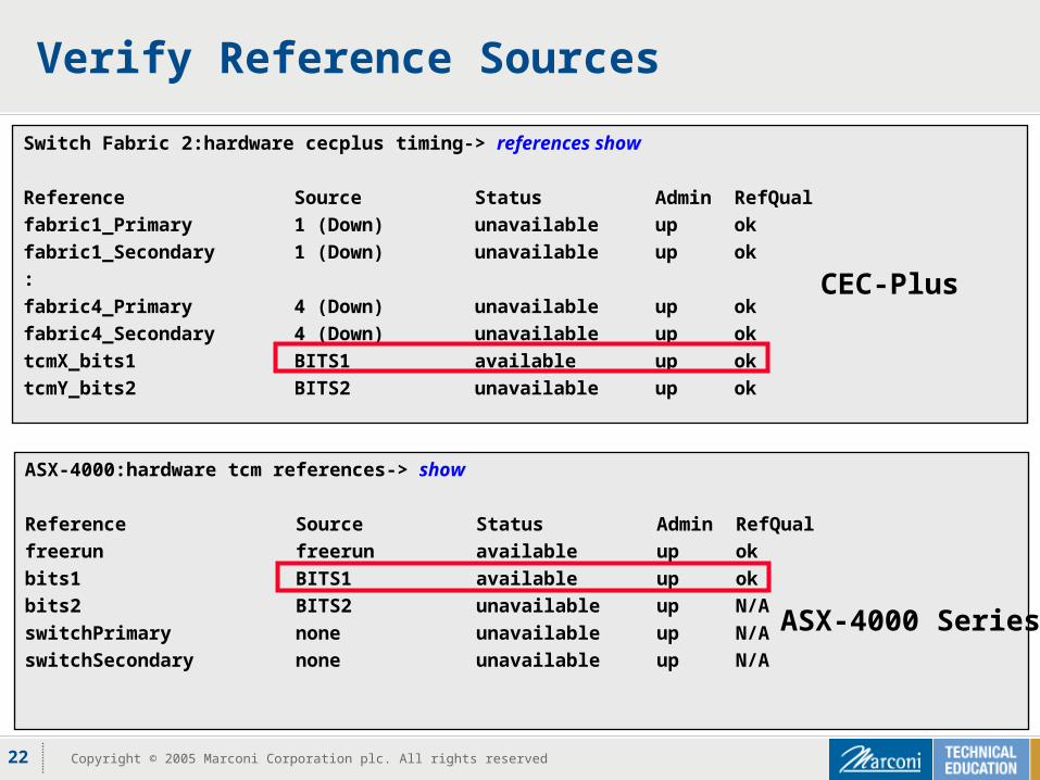
Verify Reference Sources
Switch Fabric 2:hardware cecplus timing-> references show
Reference Source Status Admin RefQual
fabric1_Primary 1 (Down) unavailable up ok
fabric1_Secondary 1 (Down) unavailable up ok
:
fabric4_Primary 4 (Down) unavailable up ok
fabric4_Secondary 4 (Down) unavailable up ok
tcmX_bits1 BITS1 available up ok
tcmY_bits2 BITS2 unavailable up ok
ASX-4000:hardware tcm references-> show
Reference Source Status Admin RefQual
freerun freerun available up ok
bits1 BITS1 available up ok
bits2 BITS2 unavailable up N/A
switchPrimary none unavailable up N/A
switchSecondary none unavailable up N/A
ASX-4000 Series
CEC-Plus
23 Copyright © 2005 Marconi Corporation plc. All rights reserved
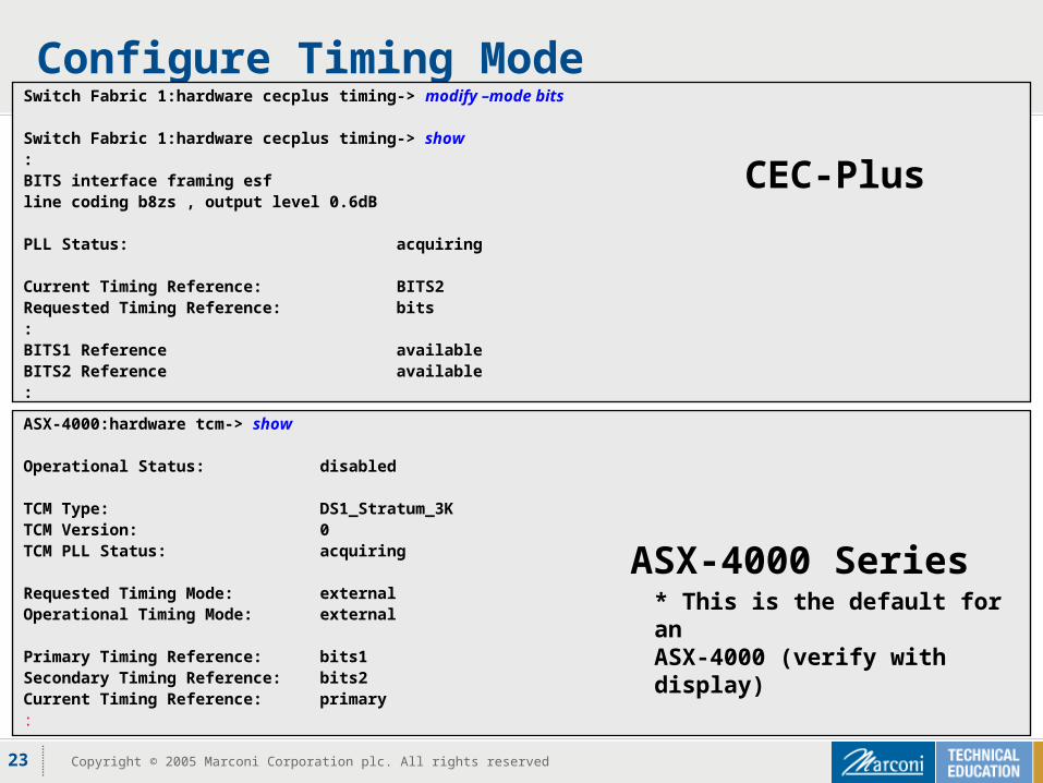
Configure Timing Mode
ASX-4000:hardware tcm-> show
Operational Status: disabled
TCM Type: DS1_Stratum_3KTCM Version: 0TCM PLL Status: acquiring
Requested Timing Mode: externalOperational Timing Mode: external
Primary Timing Reference: bits1Secondary Timing Reference: bits2Current Timing Reference: primary:
ASX-4000 Series* This is the default for an ASX-4000 (verify with display)
Switch Fabric 1:hardware cecplus timing-> modify –mode bits
Switch Fabric 1:hardware cecplus timing-> show:BITS interface framing esfline coding b8zs , output level 0.6dB
PLL Status: acquiring
Current Timing Reference: BITS2Requested Timing Reference: bits:BITS1 Reference availableBITS2 Reference available:
CEC-Plus
24 Copyright © 2005 Marconi Corporation plc. All rights reserved
Summary
Explained the purpose of network synchronization Identified the meaning of the Stratum clocking grades Listed the internal and external timing components
associated with the CEC-Plus and ASX-4000 Series TCM Described the basic distribution of timing architecture for line
timing and external timing sources Configured the IP interfaces on the CEC-Plus Configured and verify timing (external timing example) on the
CEC-Plus and the ASX-4000 Series TCM