Embed Size (px)
Citation preview


CONGRATULATIONS . . .
WELCOME TO MOBNEYvS NEW DIMENSION IN SPEED AND E C O N O m . YOUR DECISION TO SELECT A NEW MOONEY HAS PLACED YOU IN A N ELITE AND DISTINC- TIVE CLASS OF AIRCRAFT OWNERS. WE HOPE THAT YOU FIND YOUR NEW MOONEY A UNIQUE FLYING EXPERIENCE, WHETHER FOR BUSINESS OR P L E A S m E , THE MOST PROFITABLE EVER.
This manml is provided a s an operating guide for the Mooney 201, Model M20J. It i s important that you-- regardless of your previous experience--carefully read the handbook from cover to cover and review it frequently.
A11 information and i%%ustrations in the manual a r e based on the latest product information avaibble a t the time of publication approval. The right is reserved to make changes at any t ime without notice* Every effort has been n2ade to present the material in a clear and conveniea2t manner to enable you to use the manual as a ready reference, Yobar cooperation in reporting presentation and content recommendations i s solicited.
IZEVISPNG THE MAWUA %
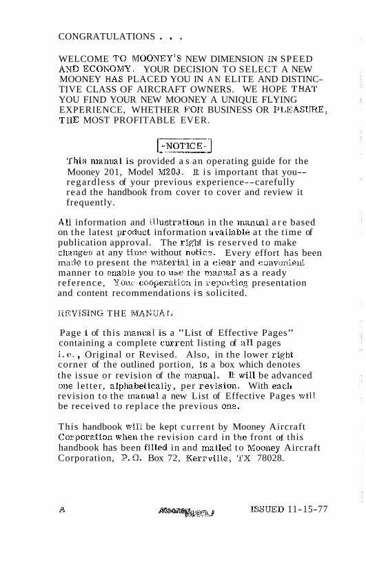
Page i of this manual is a "List of Effective Pages" containing a complete e tarent listing of aXB pages ie e. , Original or Revised. Also, in the lower corner of the outlined portion, is a box which denotes the issue or revision of the manual. It will be advanced one let ter , a%phabetica%%y, per revision, With each revision to the manual a new List of Effective Pages wi l l be received to replace the previous one*
This handbook will be kept current by Mooney Aircraft Corporation when the revision card in the front of this handbook has been filled in and mailed to Mooney Aircraft Corporation, P.O. Box 72, Kerrville, TX 78028.
A ISSUED 11-15-77


TABLE OF CONTENTS
SECTION
. . . . . . . . . . . . . . . . GENEGAL a
. . . . . . . . . . . . . LIN.w~ITATIONS. 2
. . . . . . EMERGENCY PROCEDURES 3
. . . . . . . . NORMAL PROCEDURES 4
PERFORMANCE . . . . . . . . . . . . . 5 . . . . . . . . . . WEIGHT & BALANCE 6
AIRPLANE (k SYSTEM . . . . . . . . . . . DESCRIPTIONS 7
WANE>L1.NG9 SERVICE . . . . . . . . . & MAINTENANCE. 8
. . . . . . . . SUPPLEMENTAX, DATA 9
ISSUED 1%-15-77 f s r . 4 v/v6 BLANK


SECTION I.
TABLE OF CONTENTS
TITLE PAGE
%RREEwE&SP. . . o o a . . . . a e l - 2 mTRODUCT%ON a * * * 01-3 DESCmPTIVE DATA * * a * *I-3
LANDmGGEAR * - * * * * a -1-3 ~N~~~~~~~~~~~~~~~~~~ 01-3 PROPELLER* a 0 o e * e o e o o . el-4 ~ ~ ~ ~ ~ ~ ~ ~ ~ ~ ~ ~ ~ ~ ~ o o ~ ~ *I-4 O I L . . . . . . . . . . . . . . . . .I-4 MAXMUM CERTIFICATED WEIGHTS -1-4 STANDARD MRPLANE WEIGHTS * * 0 1-5 BAGGAGESPACE& ENTRY
DIMENSIONS, . . . . . . . . . . - 1 - 5 SPECIFIC LOADINGS . 0 . . 0 a . 1-5
SYMBOM, ABBREVUTPONS & TERMI- N O L a P . . . . . . . . . . . . . I -5
GENERA18 AIRSPEED TERmNOLmV & BYMBOW. . . . . a . e . . . . 1-5
ME TEOROLWICAL TERMINO
A m P U N E PERFORMANCE & FLIGHT P U N N N G T E R m O
WEIGHT & B A U N C E T E R m O
ISSUED 11-15-77
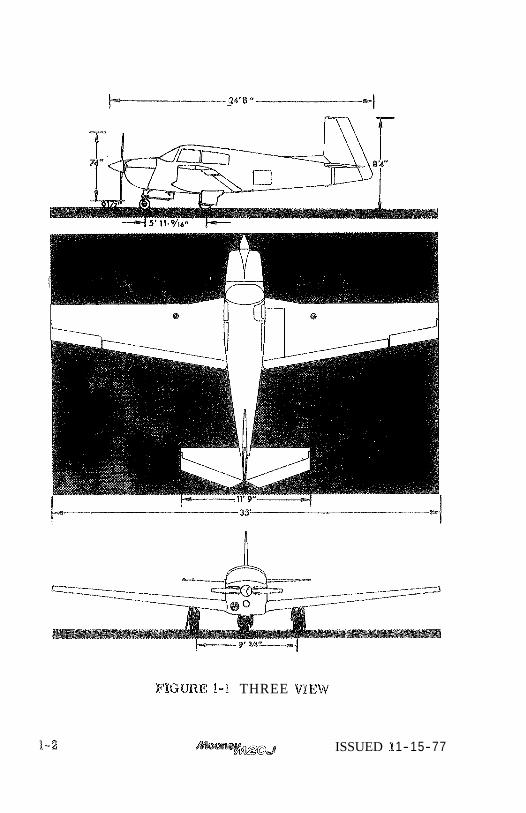
F I G m E 1-1 THREE m E W
ISSUED f 1-15-77
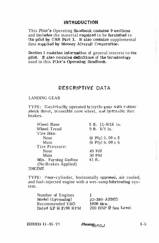
This R l o t 's Operating h n d b s o k contaim 9 dscections and includes the material r q u i r e d t o be fwnished t o the pilot by CAR Part 3. It also con%ea%m supplemental data s u p p l i d by Mooney A i r c r d t Corporation,
Section I contains informtian of general interest t o the pi%&, It aalo contains &finitions of the t e r m i n o l ~ used in this Pilot's 9 e r a t i q andbook.
DESCRIPTIVE DATA
LANDING GEAR
TYPE : Electri ca%Q operated tricycle gear with ri~bber shock discs, steerable nose wheel, and hydraealfc disc brakes.
Wheel Base 5 We 11-9/16 in. Wheel Tread 9 ft. 3/4 tn, Tire Size:
Nose (8 Ply) 6 . 0 0 ~ 5 Main (6 Ply) 6 80 x 6
T i re Pressure: Nose 49 PSI Main 30 PSI
Mino T u n i n g m d i u s 41 ft* (No Brakes Applied)
ENGWE
TYPE : Four- cylinder, horizontally opposed, air cooled, and fuel-injected engine with a wet-sump lubricatiw sys- tem.
Number of Engines 1 Mode% (Lycomiw) IO-860-A3B6D Recommended TBO 1BOO Hrs- m t e d H P @ 29106 RPM 200 BNP @ Sea Level
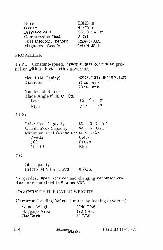
Bore 5.3125 in. S r o k e 4.375 in. Msphcement 361.0 Cu. In- Compression Ratio 8.7:1 Fuel Injector, Bend& RSA-5-AD1 Magnetos, Bendix MLN 2021
PROPELLER
TYPE : Constant- speed, hy&aulically controlled pro- peller with a siwle-acting governor.
M d e l (McCauley) ~ 2 ~ 3 4 @ 2 1 4 / 9 0 ~ ~ ~ - 16E Diameter 974 in. m m ,
73 in, miw. Number of Blades 2 Blade Angle @ 30 In. Sa. :
Low 1 3 . 9 ~ - + ,2" Nigh 33" - -I- .5"
'Total Ftas%, Capaci,ty 66-5 11.8. Gal. Usable Fuel Capacity 64 U . 9 . Gal . Minimum Fuel Octane Rali2x & Color
Grade P
1.08 100 LL Blue
oil Capacity (6 QTS MIN for f lgh t ) 8 WS.
Oil grades, speciffeatioaas and changing recornmen&- tloaas are contained in Seetion WE.
MAXMUM CERTIFICATED WEIGHTS
Maimurn Loading ( m l s s s limited by loading envelope): Gr sss Weight 2'740 LBS. Baggage Area 120 LBS. Hat Rack 10 LBS.
ISSUED 11-15-77
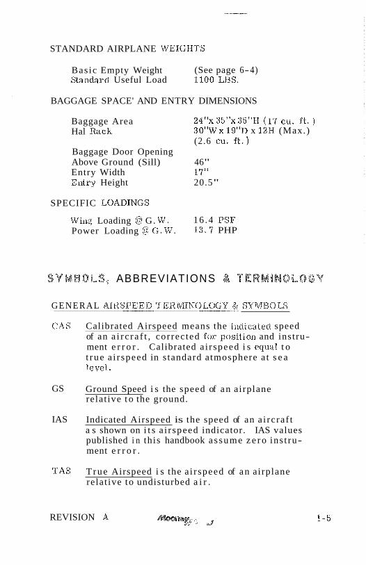
STANDARD AIRPLANE WEIGIlTS
Bas ic Empty Weight (See page 6-4) Standard Useful Load 1100 LBS.
BAGGAGE SPACE' AND ENTRY DIMENSIONS
Baggage Area 24"x 35"x 35"M (199 cu. ft . ) Hal Rack 30"Wx 19"D x 12H (Max.)
(2.6 C U . f e . ) Baggage Door Opening Above Ground (Sill) 46" Entry Width 1'9" Elltry Height 20.5"
SPECIFIC LOADINGS
Wing Loading @ G. W . 16 .4 PSP Power Loading @ C . W . 13 . '7 PHP
SYMBOLS, ABBREVIATIONS & TERMBNOLOGV
GENERAL AIRSPEED TERMINOLOGY & SYIMBOLS
CAS Calibrated Airspeed means the ia~dicated speed of an a i r c r a f t , cor rec ted for position and instru- ment e r r o r . Calibrated a i r speed i s equal t o t rue a i r speed in s tandard atmosphere a t s e a Bevel.
GS Ground Speed i s the speed of an airplane relat ive t o the ground.
IAS Indicated Airspeed is the speed of an a i rc raf t a s shown on i t s a i r speed indicator. IAS values published i n this handbook a s sume z e r o ins t ru- ment e r r o r .
TAS True Airspeed i s the a i r speed of an airplane relat ive to undisturbed a i r .
REVISION A '- J

Maneuvering -- Speed is the maximuin speed at which application of full available a e r odynamic control will not overs t ress the airplane.
Maximum Flap Extended Speed i s the highest speed permissible with wing flaps in a pre- scr ibed extended position.
Maximum b,andiiag Gear Extended Speed is the maximum speed at which an a i rc raf t can be safely flown with the landing gear extended.
Maximum Landing Gear Operating Speed is the maximum speed at which the landing gea.r can be safely extended or re t rac ted .
Never Exceed Speed or Mach Number i s the speed linait that may not be exceeded at any t ime.
Maximum Striactriral Cruising Speed i s the speed Chat should not be exceeded except i n smootla air and thela only wit la caution.
Stalling Speed or the 1aainirnu.m steady flight speed at which tlae airplane i s contm-obkable.
Stalling -- Speed or the rni.nimum steady flight speed at which the airplane i s controllable in the landing configuration
Best Angle-of-Climb Speed -. i s the a i r speed which de l ivers the greatest gain of alti tude in the shor tes t possible horizontal distance.
Best Rate-of-Climb Speed i s the a i r speed which de l ivers the greatest gain in altitude in tlae shor tes t possible t ime with gear and flaps up.
ISSIJED 11-15-77
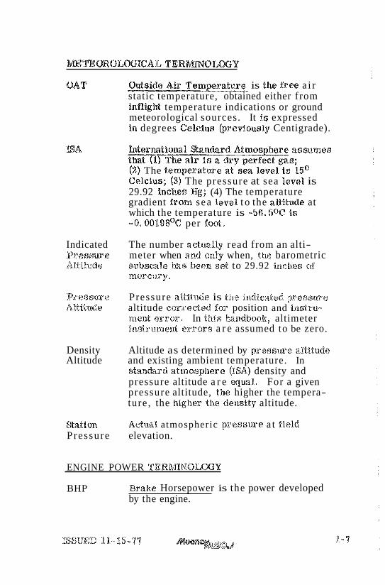
OAT is the free a i r static temperature, obtained either from inflight temperature indications or ground meteorological sources. It is expressed in degrees Celcius kref iously Centigrade).
(2) The temperatwe a tvsea l e v e l s kQ Celeius; (3) The pressure at sea level is 29.92 inches Hg; (4) The temperature gradient from sea level t o the aanfteads at which the temperature is -56.5oC is - 0 . 0 0 1 9 8 ~ ~ per foot.
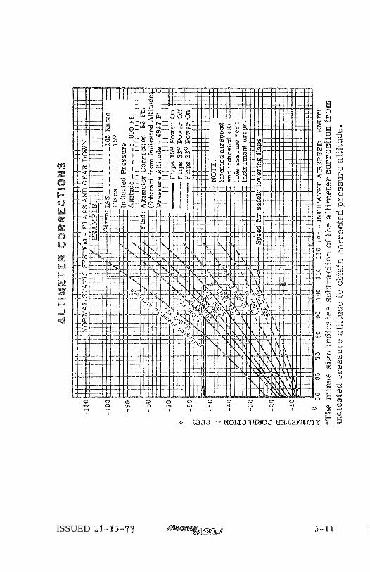
Indicated The number actually read from an alti- Pressure meter when and only when, the barometric ARLMuds subscale has been set to 29.92 inches of
mer cusy.
Reasears Pressure altitude is the tx~dicated pressure Altitude altitude corrected Pos position and fnstru-
mealt error, In this handboolc, altimeter instrument e r r o r s a r e assumed to be zero.
Density Altitude as determined by p ressme altitude Altitude and existing ambient temperature. In
stan&rd atmospiaere (ISA) density and pressure altitude a r e equal, For a given pressure altitude, the higher the tempera- ture , the higher the density altitude.
&atio%% Actual atmospheric p r e s s w e a t field Pressure elevation.
ENGINE POWER TERMINOLaY
BHP Brake Horsepower is the power developed by the engine.
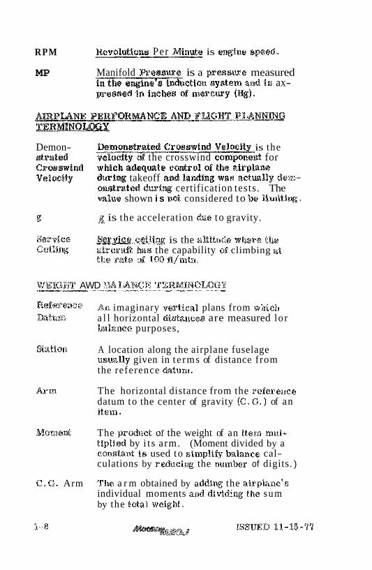
RPM Revollutions Per Minute is @wine speed.
MP Manifold R e a e u r e is a presswe measured &%on syatem awd ts ax-
Demon- is the e t r a t d velocftv d the crosswind component for Croeswiond which i d q m t e control of the i t rp lane VelmiQ dw%w takeoff and landing wae actmlly dem-
onadrated desriw certification tests . The mllue shown i s n& considered to be lirnitim,
E! g is the acceleration due to gravity.
&tpdee is the altitude where the Ceiligg a i r e r a 8 has the capability of climbing at
the rats d 100 lt/min.
WEHCBT AWD BALANCE TERMINQImU p7-.--p----p."p
Reference An imaginary vertical plans from which h t u m a l l horizontal distances are measured lor
balance purposes,
Wation A location along the airplane fuselage usw%%y given in t e rms of distance from the reference datum*
A r rn The horizontal distance from the reference datum to the center of gravity (C. G. ) of an item.
Moment The p r d u c t of the weight of an item mu%- tiplied by i t s arm. (Moment divided by a constant i s used to simp%i$gv balance cal- culations by rdiacing the number of digits. )
C . G. Arm The a r m obtained by addiw the airplane's individual moments and d i ~ d i n g the sum by the total wsigkat.
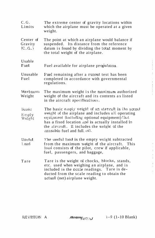
C . G . The extreme center of gravity locations within Limi ts which the airplane must be operated a t a given
weight.
Center of The point a t which an airplane would balance if Gravity suspended. Its distance from the reference (C . G. ) datum i s found by dividing the total moment by
the total weight of the airplane.
Usable Fuel Fuel available for airplane pro;ulsion.
Unusable Fuel remaining af ter a runout tes t has been Fuel completed in accordance with governmental
regulations.
Maximurn The maximum weight i s the maximum authorized Weight weight of the a i rc raf t and i t s contents a s listed
in the a i rc raf t specificatio~as.
Bas ic The basic empty weigh"c. of an a i rc raf t is the actual Empty. weightof the airplane and includes a l l operating Weight egurnpmclat (imcliading optional equipment) t k t
has a fixed location and is actually installed in the airc-sa.ft. It includes t he weight 0%: the unusable fuel and full. oil ,
Useful 'Fhe useful load is the empty weight subtracted Load f r o m the maximum weight of the a i rc raf t . This
load consis ts of the pilot, c rew if applicable, fuel, passengers , and baggage,
T a r e T a r e i s the weight of chocks, b%oclns, s tands, e tc . used when weighing a n airplane, and i s included in the sca le readings. T a r e i s de- ducted f rom the sca le reading t o obtain the actual (net) a irplane weight.
1 - 9 (1-10 Blank)


SECTION II . TABLE OF C O N T E W S
TITLE PAGE
INTRODUCTION . . . . . . . . . . . . . . . . . . . 2-2 AIRSPEED WmATIIONS . . . . . . . . . . . . . . 2-3 AGRSPE ED INDICATOR MARKmGS . . . . . . . . . 2-4
. POWER P U N T LIMITATIONS . . . . . . . . . . . 2-5 POWER PLANT INSTRUMENT MARmNGS . . . . 2-6 WEIGHT UM%TS . . . . . . . . . . . . . . . . . . 2-7 CENTER OF GRAmTU UMITS . . . . . . . . . . . 2-7 MANEUVER W M E S . . . . . . . . . . . . . . . . . 278 FUGHT LOAD FACTOR WMTS . . . . . . . . . 2-9 MIND$ OF OPERATION LIMT~S . . . . . . . . . . . 2-9 FUEELIMmATTONS . . . . . . . . . . . . . . . 2-9 OTHER INSTRUMENTS AND MARKING8 . . 0 2-9
. . . . . . . . . . . . . . . DECAL, 9 & PMCARDS 2-10 INTERIOR . . . . . . . . . . . . . . . . . 2-10 EXFERIQR* = . . . . . . . . . . 2-13
FAA APPROVED ISSUED 11-15-77
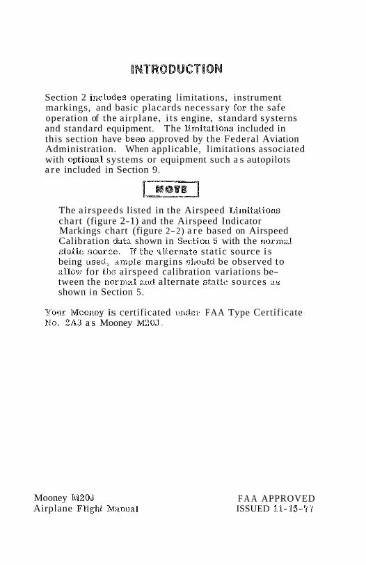
Section 2 includes operating limitations, instrument markings, and basic placards necessary for the safe operation of the airplane, i t s engine, standard sy sterns and standard equipment. The %imitations included in this section have been approved by the Federal Aviation Administration. When applicable, limitations associated with optional systems or equipment such a s autopilots a r e included in Section 9.
The airspeeds listed in the Airspeed Limitations chart (figure 2-1) and the Airspeed Indicator Markings chart (figure 2-2) a r e based on Airspeed Calibration &ata shown in Section 5 with the normal static source. Kf the alternate stat ic source i s being used, ample margins sllould be observed to allow for the airspeed calibration variations be- tween the ~aormal and alternate static sources a.s shown in Section 5.
Your Moaney is certificated under FAA Type Certificate No, 2A3 a s Mooney M20J0
Mooney M20J Airplane Flight Manual
F A A APPROVED ISSUED 11-15-77
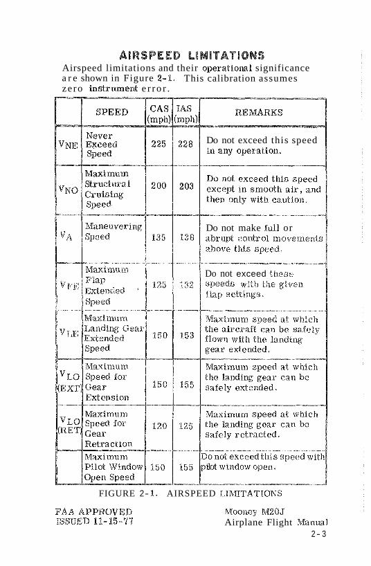
AIRSPEED LlMITATION3 Airspeed limitations and their operatiom% significance a r e shown in Figure 2-1. This calibration assumes ze ro instrument e r r o r .
Do not exceed this speed
Do not make ful l or
Do not exceed these
FIGURE 2- 1 . AIRSPEED L%M%TATIONS
Mooney M2OJ Airplane Flight Manual
2- 3
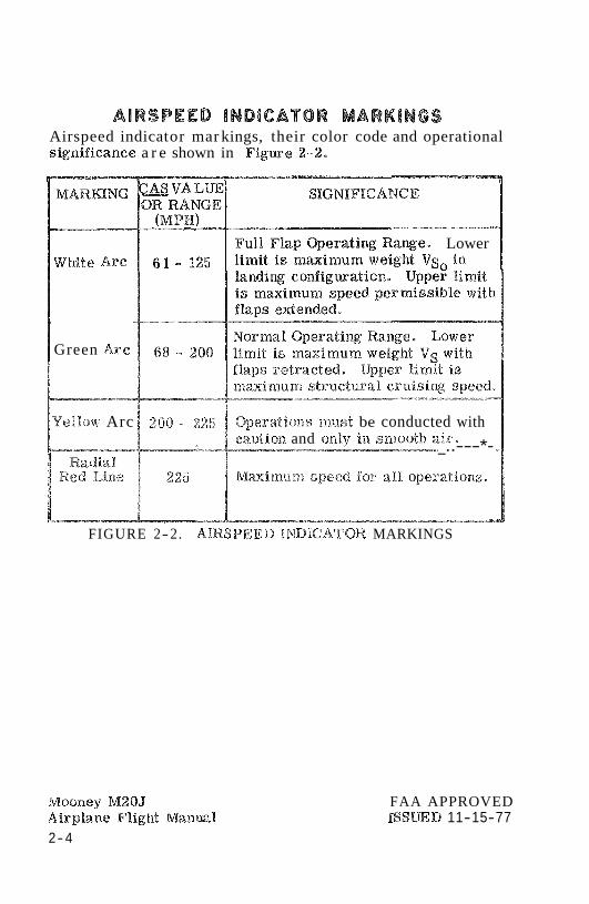
AIRSPEED lNDlCATOR MARKINGS Airspeed indicat or mar kings, their color code and operational significance a r e shown in Figwe 2-2 ,
white Arc
Green Arc
Full Flap wera t ing R a x e . Lower
Yellow Arc 1 200 - $25 1 @eratfons nlust be conducted with caution and only- in smooth air,
-*-- .. wvm-m- L--...,.i - - - - - - . ' _..---*-
FIGURE 2-2. A R S P E E D I m I G A T O R MARKINGS
Mooaaey M20J Airplane F%igh% Manawal 2- 4
FAA APPROVED ISSWD 11-15-77
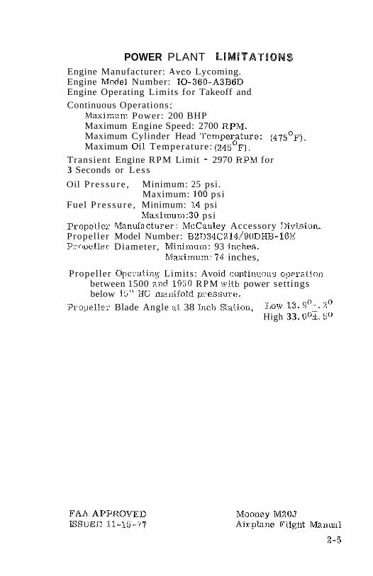
POWER PLANT L iMlTATlONS Engine Manufacturer: Avco Lycoming. Engine Model Number: 10-360-A3B6D Engine Operating Limits for Takeoff and Continuous Operations :
Maxinlum Power: 200 BHP Maximum Engine Speed: 2700 RPM. Maximum Cylinder Head Temperature: ( 4 ~ 5 ' ~ ) . Maximum Oil Temperature: ( 2 4 ~ ~ ~ ) .
Transient Engine RPM Limit - 2970 RPM for 3 Seconds or Less
Oil P re s su re , Minimum: 25 psi. Maximum: 100 ps i
Fuel P re s su re , Minimum: 14 psi Maximutn:30 psi
Propeller 1Vlariufacturer: McCataley Accessory Division. Propeller Model Number: ~ 2 % ) 3 4 6 2 % 4 / 9 0 ~ ~ ~ - 1 6 E P rn~e lEe r Diameter, Minimeam: 93 inches,
Maximum: 74 inches,
Propeller Operating Limits: Avoid contineeous operation between 1500 and 71950 RPM w i t h power settings below 15" HG manifold p r e s s w e .
Propeller Blade Angle 3.t 38 Inch Station, IJ~W 13. go-+, 2" High 33. -- 50
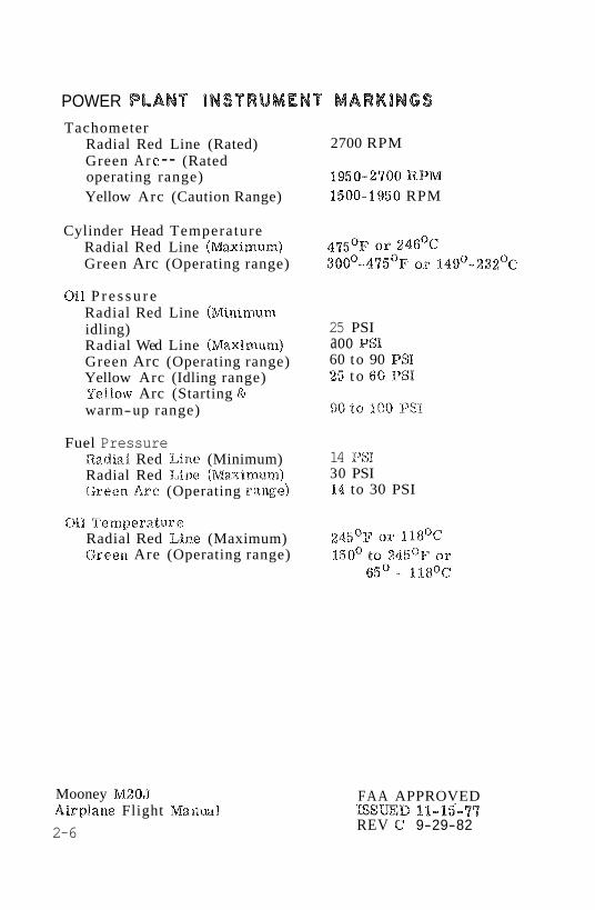
POWER PLANnlNSTRUMENT MARKINGS Tachometer
Radial Red Line (Rated) Green A r c -- (Rated operating range) Yellow Arc (Caution Range)
Cylinder Head Temperature Radial Red Line (Maximum) Green Arc (Operating range)
Oil P r e s s u r e Radial Red Line (Minimum idling) Radial Wed Line (Maximum) Green Arc (Operating range) Yellow Arc (Idling range) Yellow Arc (Starting & warm-up range)
Fuel Pressure Radia.1 Red Line (Minimum) Radial Red Llrae (Maxianurn) Green Arc (Operating range)
811 'Remperature Radial Red Line (Maximum) Green Are (Operating range)
Mooney M205 Airplane Flight Manml
2-6
2700 RPM
1950-2700 RPM 1500-1950 RPM
25 PSI aoo PSI 60 to 90 PSI 25 t o 60 PSI
14 PSI 30 PSI 14 to 30 PSI
FAA APPROVED assmD 11-15-77 REV C 9-29-82
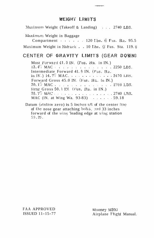
Maximum Weight (Takeoff RL Landing) . . . . 2740 LBS.
Ma%irnurn Weight in Baggage Compartment . . . . . . 120 Lbs. @ Fus. § & a . 95.5
Maximum Weight in Haln.aclc . . 10 Lbs. @ Fus. Sta. 119. 0
CENTER OF GRAVITY L l M l T S (GEAR DOWN) Most Forward 41.0 IN. (Fus. %a. i n IN. ) 13.4'; MAC . . . . . . . . . . . . . . 2250 LBS. Intermediate Forward 41. 8 IN. (Fus , Wa. i n I N . ) 14,7? M A C . . . . . . . . . . . . . 2470 EBS. Forward Gross 45 .0 %Ed. (Fus . Wa. in IN .) 2 0 . 1 5 MAC . . . . . . . . . . . . . . 2'540 LBS. Rear G r o s s 50 .1 IN. (Fus. Ra. in IN. ) 2 8 . 9 7 MAC . . . . . . . . . . . . . . . . . 2740 LBS. MAC (IN. at Wing Wa. 93-83) . . . . . . . 59.18
Datum (station zero) is 5 inches aft of the center line of the nose gear attaching bol ts , and 33 inches forward of the wing 'leading edge at wing station 59. 25.
F A A APPROVED ISSUED 11-15-77
Mooney M209 Airplane Flight Manual.
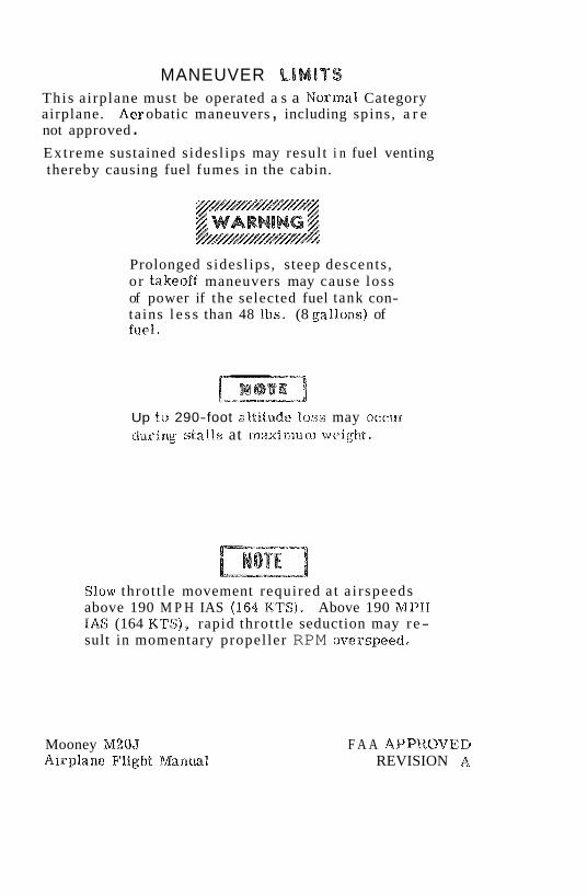
MANEUVER LIMITS This airplane must be operated a s a Norma% Category airplane. Aer obatic maneuvers , including spins, a r e not approved . Extreme sustained sidesl ips may resul t i n fuel venting thereby causing fuel fumes in the cabin.
Prolonged sidesl ips , steep descents , o r takeoff maneuvers may cause loss of power if the selected fuel tank con- tains l e s s than 48 Ibs. (8 gallons) of fuel.
Up &a 290-foot altitude loss may occur dur ing s ta l l s at max imum weight.
Slow throt t le movement required a t a i r speeds above 190 M P H IAS (I64 K'TS). Above 190 M P H %AS (164 KTS), rapid throt t le seduction may r e- sult in momentary propel ler RPM overspeed.
Mooney M20J Airplane Flight Wlantaal
F A A APPROVED REVISION A
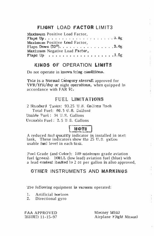
PLlGHT LOAD FACTOR LIMIT3 m i m u m Positive Load Factor, F b p s u p a . . . . . . . . . . . . . . . . . . * 3 . 8 g m i m u m Positive Load Factor, Flaps m w n (33OI0 . . . . . . . . . . . . . . .2.% Mmimum Negative Load Factorsk, . . . . . . . . . . . . . . . . . . . Flaps Up 1.5g
KlNDS OF OPERATION LIMITS Do not operate in h o w n i c i ~ conditions,
This is a Normal c i tegory a i r c r d t approved for V F R / I F R / ~ ~ ~ or night operations, when quipped in accordance with FAR 91,
F U E L LIMITATIONS 2 W a n b r d Tanks: 93.25 U. S , Gal%o~~s Eacia
Total Fuel: 66 -5 U. 8. Galloss Usable Fuel : 84 U. S* Gallons Usamable Fuel : 2* 5 U. S . Gallons
A reduced fuel qmntity indicator is installed in each lank, These indicators show the 25 U. S. gallon usable fuel %eve% in each t a n k
Fuel Grade (and Color): 100 minimum grade aviation fuel (green)%). 106LL (low lead) aviation fuel (blue) with a lead eontent limited to 2 ec per gallon is also approved,
OTHER INSTRUMENTS AND MARKlNGS
The liollowing equipment i s mcuum operated:
1, Artificial horizon 2. Directional gyro
FAA APPROVED PS$WD 11-15-97
Mooney M20J Airplane FligM Ed%anml
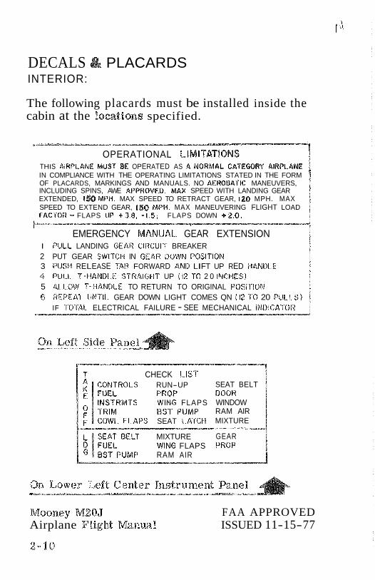
DECALS PLACARDS INTERIOR:
The following placards must be installed inside the cabin at the locations specified.
OPERATIONAL LlMl"$T!$sONS THIS AIRPLANE MUST BE OPERATED AS n saloaMae CATEGORY AIRPLANE IN COMPLIANCE WITH THE OPERATING LIMITATIONS STATED IN THE FORM OF PLACARDS, MARKINGS AND MANUALS. NO AEROBATIC MANEUVERS, INCLUDING SPINS, AWE APPRQVED. MAX SPEED WITH LANDING GEAR EXTENDED, 1% MPH. MAX SPEED TO RETRACT GEAR, 120 MPH. MAX SPEED TO EXTEND GEAR, 150 MPH. MAX MANEUVERING FLIGHT LOAD FACTOR - FLAPS I1P +3.8 , -1.5; FLAPS DOWN +2.O.
EMERGENCY MANUAL GEAR EXTENSION I PULL LANDING GEAW CIRCUIT BREAKER 2 PUT GEAR SWITCH IN GEAW DOWN POSITION 3 PUSH RELEASE TAB FORWARD AND LIFT UP RED HANDLE kg PULL P -HANDLE STRiCalGHT UP (12 10 2 0 INCPIFS) 5 ALbQW T-HANDLE TO RETURN TO ORIGINAL POSITION 6 REPEAS IlNTlL GEAR DOWN LIGHT COMES QN (12 TO 20 PULL 5 )
IF TOTAL ELECTRICAL FAILURE - SEE MECHANICAL INBlCA'rOR b---p -- -------a
? CHECK LIST ROLS RUN-UP
PROP MTS WING FLAPS
BST PUMP SEAT LATCH
MIXTURE WINS FLAPS
UMP RAM AIR
SEAT BELT BOOR WINDOW RAM AIR MIXTURE PP
GEAR PROP
Mooney M20J FAA APPROVED Airplane Flight Manual ISSUED 11-15-77
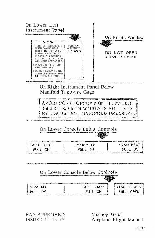
On Lower Left Instrument Panel
I TURN OFF STROBE LTS WHEN TAXIING NEAR OTHER ACFT OR WHEN FLYING I N FOG OR IN CLOUDS S T 0 POSITION LTS MUST BE USED FOR A L L NIGHT OPERATIONS.
2 IN CASE OF FIRE TURN OFF CABIN HEAT.
3 DO NOT SCREW VERNIER CONTROLS CLOSER THAN I/@" FROM NUT FACE.
PULL FOR ALTERNATE
SVATlC SOURCE
On Pilots Window
DO NOT OPEN ABOVE 150 M.P.H.
On Right Instrument Panel Below Manifold &esswe Gage
O W R S G T T IFOIB PRES
On Lower Console Below Controls
On Lower Console Below Controls
FAA APPROVED ISSUED f I- 15-77
Mooney M20J Airplane Flight Manual
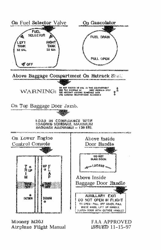
h Fuel Seledor Valve Gascobtor
BO M T %X@PD BO LI5. I W W W M M T
WARNING: Z am- m 8 . s war 4 mW WPA
@@a !!
On Top Baggage Door Jamb.
LQAD IN COMPblANeD WITH LOADING SCHEDULE. MAXIMUM W W A O E M 8 W A & % -z 8 18 MS.
Absvs Imids Door mndle
Above Inside Baggage Door mndle
. .
Mooney M2OJ FAA APPROVED Airplans FHgbt Manual ISSUED 11-15-97
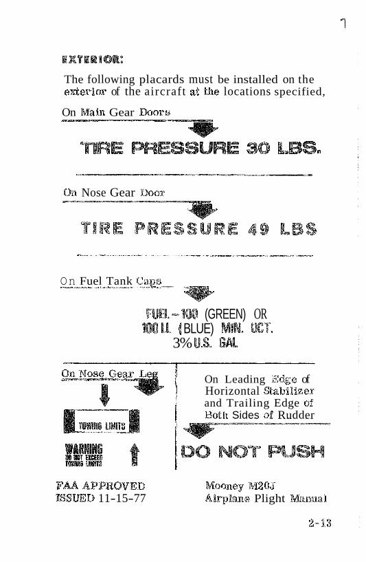
EXTERIOR:
The following placards must be installed on the eAerior of the aircraft at the locations specified,
On mfn Gear mars
TIRE ESSURE 38 LBS.
On Nose Gear Boor
On Fuel Tank CaE <------- , ---.-
FUR-100 (GREEN) OR 100 ILL ( BLUE) MIN, 86T.
3% U.S. G b l
On Leading Edge of Horizontal Wabilizer and Trailing Edge of Both Sides of Rudder
DO NOT PUSH
FAAAPPROVED Mooney M2 05 LSSWD 11-15-77 Airphne Plight Manual
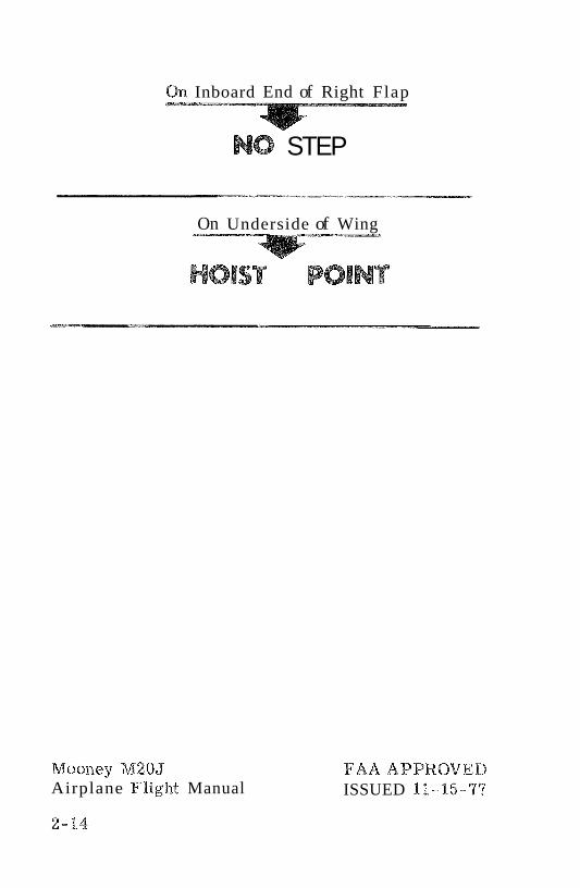
On Inboard End of Right Flap
NO STEP
On Underside of Wing
HOIST POINT
Mooney M20J Airplane Flight Manual
FAAAPPROVEB ISSUED 11-15-,7'%
This sect ion provides the recommended procedures t o follow during adve r se flight conditions. The infor ma- tion i s presented t o enable you t o form, in advance, a definite plan of action for coping with the most probable emergency situations which could occur in the operation of your airplane.
A s it is not possible t o have a procedure for a l l types of emergencies that may occur, it is the pilot's resgonsi- bility t o u se sound judgement based on experience and knowledge of the a i r c r a f t t o determine the best cou r se of action. Therefore , It i s considered mandatory that the pilot r e a d the en t i re manual, especially th i s section before flight.
When applicable, emergency procedures associated with optional equipment such a s autopilots a r e included in Section 9,
AlR ai.rspeeds in t h i s section. a re indicated (IAS) and assume zero instrument error unless s taled otkaerwise.
ISSUED 11-15-97

ANNUNCIATOR PANEL WARNING LIGHTS
Warning Lf ght Fault & Remedy
Gear Unsafe Landing gear is not in fully extended/ retracted position. Refer to "Failure of landing gear to extend electrically" procedure on page 3-8 or "Fail~are of landing gear to retract after take- off" procedure on page 3- %%.
Left or Right Fuel Low 2 1/2 to 3 gallons of fuel remain in
the respective tanks. Switch lo fuller tank,
VAC: (Flashing) Suction is below4$5 inches of mercury.
VAC (Steady) Suction i s above? 5.5 inches of mesceary. Attitude and d f r e c t i o a ~ l gyros are ura- reliable, Vacuum system shoeald be c11sclced and/or adjusted as soon a s practicable.
Volts (FSasBaing) I,ow voltage.
Volts (Steady) Overvoltage or trippage of voltage relay. Refer to "Alternator Power Loss" on page 3- 9.
Ram A i r Ram a i r door is open (when landing gear e%eended); close before landing.
REVISION A
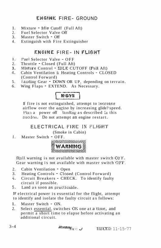
ENGlNE FIRE- GROUND
1. Mixture - Idle Cutoff (Full Aft) 2. Fue l Selector Valve Off 3. Master Switch - Off 4 . Extinguish with F i r e Extinguisher
ENGINE F I R E- IN FLIGHT 1. Fuel Selector Valve - O F F 2. Throttle - C losed (Full Aft) 3 . Mixture Control - IDLE CUTOFF (Full Aft) 4. Cabin Ventilation & Heating Controls - CLOSED
(Control Forward) 5. Landing Gear - DOWN OR U P , depending on t e r r a i n . 6. Wing Flaps - EXTEND. As Necessary.
If f i r e i s not extinguished, attempt to iaacseaae airflow over the engine by increasing glide? speed. PIaxr a power off landing a s described in th i s sectlola, Do not attempt an engine r e s t a r t .
E L E C T R I C A L 68RE I N FLIGHT (Smoke in Cabin)
1. Master Switch - OFF. y//////////////////// $$WARNING # MMMHMMH~
Stall warning i s not available with master switch OFF. Gear warning i s not available with mas ter switch OFF.
2. Cabin Ventilation - Open 3. Heating Controls - Closed (Control Forward) Lg* Circuit B reake r s - CHECK. To identify faulty
circui t i f possible. 5, Land a s soon as pract icable,
If e lec t r ica l power i s essent ia l for the flight, a t tempt t o identify and isolate the faulty circui t a s follows:
1. Master Switch - ON. 2. Select essential. switches ON one a t a t ime , and
permit a shor t t i m e t o elapse before activating an additional c i rcu i t .
3-4 '1-> J ISSUED 11-15-77
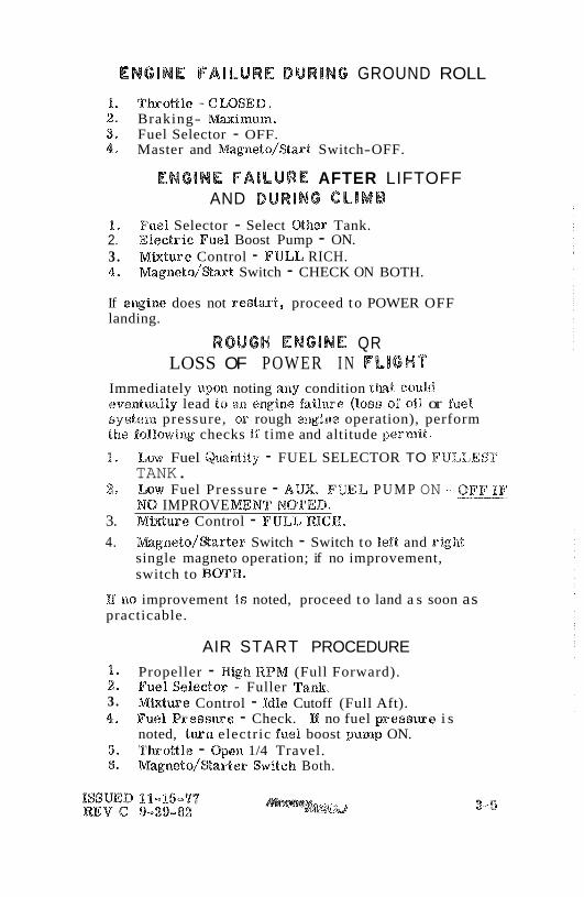
ENGINE FAILURE DURING GROUND ROLL
1. Throttle-CLBSED. 2. Braking- Maximum. 3. Fuel Selector - OFF. 4. Master and Magneto/%art Switch-OFF.
ENGINE FAILURE AFTER LIFTOFF AND DURING CLIMB
1, Fuel Selector - Select Other Tank. 2. Electric Fuel Boost Pump - ON. 3. Mixture Control - FULL RICH. 4, ~ a ~ n e t o / % a r t Switch - CHECK ON BOTH.
If emgine does not $e8&2irt9 proceed t o POWER OFF landing.
ROUGH ENGINE QR LOSS OF POWER I N FLIGHT
Immediately upon noting any condition Chat could evel~tually lead $0 arz engine failrrre (loss of oil or fuel system pressure, or rough epxsgixae operation), perform the falBowing checks if t ime and altitude permit.
1. Low Fuel Qasaiatity - FUEL SELECTOR TO FULLEST TANK.
2 Low Fuel Pressure - AUX. FUEL P U M P ON - OFF IF .." NO IMPROVE W N T NO'FED.
3. MWure Control - FIJLL RICH.
4. wgneto /%ar te r Switch - Switch to left and right single magneto operation; if no improvement, switch to BOTH,
I%$ no improvement i s noted, proceed t o land a s soon as practicable.
AIR START PROCEDURE 1. Propeller - High RPM (Full Forward). 2 Fuel Selector - Fuller Tank. 3. Mixture Control - Idle Cutoff (Full Aft). 4. Fuel R e s s w e - Check. If no fuel p r e s s m e i s
noted, turn electric fuel boost pump ON. 5. T b o g % e - Open 1/4 Travel. 6, ~ a ~ n e t o / % a r t e r Switch Both.
7, Mixture Control - Move slowly and smoothly t o FULL RICH (Forward).
8. Re-establish cruise power and RPM - then lean mistture a s required.
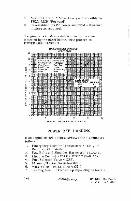
lf engine fails to s ta r t establish best glide speed indicated by the chart below, thew proceed to POWER OFF LA6dDING. -
GLIDE DISTANCE MODEL 1M20.J
POWER OFF LANDING
If an engine failure? occurs, prepare for a bwding a s fo%%ows: 1. Emergency Locator Transmitter - ON , As
Required, (if installed) 2. Seat Belts and Shoulder Harnessed- SEC mE, 3, M W w e C o n t r o l - DLECUTOFF (FullMt). 4, Fuel Selector Valve - OFF. 5. Magweto/Sarter Switch-OFF. 6. Wing Flaps - PULL DOWN (33'3 7. k n d h g Gear - Down or Up depewdilg on terrain.
ISSUED If-15-77 REV C' 9-29-82

8, Approach Speed - 8%. MPH (7%. Kts) %AS. 9. Master Switch - OFF, Pr io r to Landing.
Up to 2000 feet of altitude may be lost in a one t u r n spin and recovery; therefore , s ta l ls a t low altitude a r e extremely criticaA
The best spin recovery technique is to avoid flight conditions conducive to spin entry. Low speed flight near s ta l l should be approached with caution and excessive flight control move-- ments in this RligM regime should be avoided, Shuuld a n amintentional s ta l l occur the aircraft should not be all.owed to p rogress into a deep stall . Fast , brat smooth s ta l l recovery w i l l mininiize the r isk of progressing into a spin, If a n unusual post shall attitude develops and resul ts in a spin, quick application of anti-spin procedures should shorten the PeCOTJ6?Prys
IN'TENTIQNAE SPINS ARE PROHIBITED. In the event of an inadvertent spin, the following recovery procedure sfaorald be used:
1, Rudder - Apply FULL RUDDER opposite the direction of spin,
2 , Control Wheel - FORWARD of neutral in a br i sk motion. Additional FORWARD elevator control may be required i f t he rotation does not stop.
3. Ailerons - NE UTRAL. 4. Throttle - RETARD TO IDLE.
Hold anti-spin co&roRs until rotation stops:
5, F b p s - Bf edended, RETRACT a s soon as possible. 6. Rudder - N E m M U Z E , 7. Control Wheel - Smoothly move aft t o bring the nose
up t o a level flight attitude,
ISSUED X I - 15-77 REV @ 9-29-82
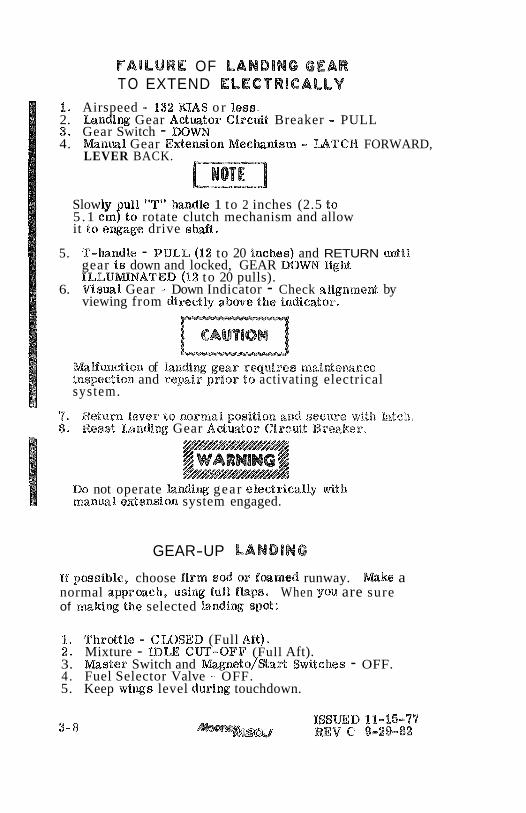
FAILURE OF LANDlNC GEAR TO EXTEND ELECTRICALLY
1. Airspeed - 132 U S o r less. 2. Landing Gear Actmtor GircGt Breaker - PULL 3. Gear Switch - IDOW 4. lvfanm% Gear E&en&on Mechnisaaa - U T C W FORWARD,
LEVER BACK.
Slowly u%l "T" Baandle 1 to 2 inches (2.5 to 5 .1 cmfto rotate clutch mechanism and allow it t s ewage drive e M t .
5. T-handle - PULL (I2 to 20 inches) and RETURN until gear 18 down and locked, GEAR DOWN light ILLLUmNATED (12 to 20 pulls).
6. Visual Gear - Down Indicator - Check alignmed by viewing from di
m H u c t i o n of Xa Beaspsetion and repa i r prior t o activating electrical system.
' 7 . Return lever $0 normal p ~ s i t i o ~ ~ and S ~ C ~ U - e !vit,d~ k"tc&l. 8. Reset Is%di~g Gear A d w t o r Ciarc%dt Breaker.
~HH/HHflHHHfl/ / WAININO 4 &MA
DO not operate k n d i w gear electrically wit11 manual. edension system engaged.
GEAR-UP LANDING
Ef possible, choose firm s& or f a m e d runway. Make a normal apprmch, using full flaps, When you are sure of makiw the selected lawdim spot:
1. Throgle - C&QSEB (Full Mt). 2. Mixture - IDLE Cm-OFF (Full Aft). 3. m s t e r Switch and m g n e t o / ~ a & Switches - OFF. 4 . Fuel Selector Valve - OFF. 5. Keep wings level d~aring touchdown.
UNLATCHED DOOR IN FLIGHT
If the cabin door is not locked it may come unlatched in flight. This may occur during or just af ter take-off. The door will t r a i l in a position approximately 3 inches open, but the flight charac te r i s t ics of the airplane will not be affected. Return t o the field in a normal manner. If practicable, during the landing flare-out have a passen- ge r hold the door t o prevent it f rom swinging open.
If it i s deemed impract ical t o re turn and land, the door can be closed in flight, a f te r reaching a safe altitude, by the fo%%owing procedures:
1. Slowtoapproximately 1 % 0 m p h / 9 6 M s e 2. Open the s t o r m window t o redrace cabin a i r p r e s s u r e . 3. Bank t o the r ight . 4 . Simultaneous%y apply left rudder (which will r e su l t i n
a right s l ip) and close the door,
ALTERNATOR POWER LOSS
If the r e d voltage warning 1i.gh.t il.turnina&es steadily, tu rn off the radio mas ter and then turn the mas t e r switch off and oaa t o r e s e t the voltage regralator. If the voltage light comes on again pull the al ternator field circui t bseaker out. A11 electrica E equipment not essent ial for flight should be turned off and the flight terminated a s soon a s pract ical t o co r r ec t malfunction. A flashing voltage light indicates low voltage caused by an a l t e r - nator malfunction, belt slippage, or tripped b reake r . If reset t ing the a l te rna tor field breaker does not r e s t o r e the a l te rna tor , tu rn off a l l e lectr ical equipment not essent ia l for the flight and te rmina te the flight as soon a s pract ical ,
A tripped main al ternator circui t b reaker can only be caused by a shorted al ternator circui t and cannot be cor rec ted by resetting the breaker . Th i s should be verified by atternpt-

ing t o r e s e t the breaker not more than one t ime. If th i s fa i l s , pull the al ternator field b reake r , t u rn off a l l non-essential e lec t r ica l equipment and te rmina te the flight a s soon a s pract ical .
DO NOT OPERATE IN KNOWN ICING CONDITIONS.
If icing conditions a r e inadvertently encountered:
1. T u r n OFF r a m a i r . Do not tu rn r a m a i r on again when enter ing c l ea r air until a s su red a l l ice and snow has melted f rom tlae a i rc raf t .
2. Shut cabin heat off until. engine operation is normal. 3. Push ON pitot heat (if installed). 4. Pul l s ta t ic air source to ALTERNATE (if installed). 5. T u r n back o r change altitude to obtain a n outside air
t empera tu re l e s s conducive to icing.
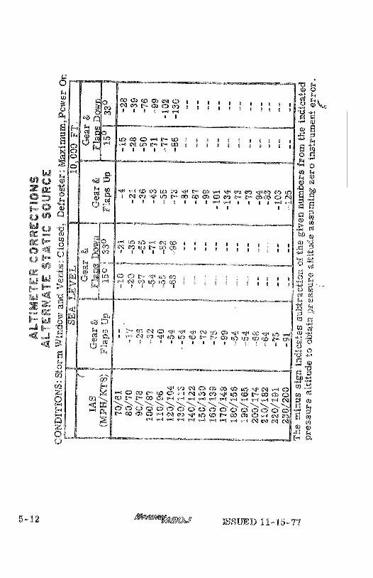
ALTERNATE STATIC SOURCE
The a l te rna te s tat ic a i r source should be used whenever it is suspected that: the raoranal. s tat ic a i r sou rces a r e blocked. Selecting the a l te rna te position changes the sou rce of s tat ic a i r for the a l t imeter , a irspeed indicator and rate-of-cl imb f rom the outside of the a i rc raf t to the cabin in te r ior .
When the a l te rna te s tat ic air source is i n u se adjust the indicated a i r speed and al t imeter readings according t o the appropr ia te a l te rna te s tat ic source a i r speed and a l t imeter cal ibrat ion tables in Section 5 .
7 he s ta t ic a i r source valve i s located in the lower left portion of the pilot 's flight panel above the pi lot ' s left knee.

FAILURE OF LANDING GEAR TO RETRACT AFTER TAKEOFF
The following procedure applies to al l aircraft modified with the airspeed safety override system with the "BY PASS" switch (S/W 24-0238 and above) and all aircraft prior with the mechani- cal squat switc!a safety override system which have been modified with the retraction "BY PASS" switch in accor- dance with Mooney Service Bulletin M20- 196.
In the event that the gear fails to retract when the landing gear control switch is placed in the "UP" position due t o the failure of the airspeed sensing or squat safety switch lo activate after takeoff, the followtlag procedure should be tased as an alternate means to allow retraction:
(I) %a &he safety swi tch fails l o actuate, a s evidenced by IEXwminationa sf the "GR SAFETY BY BASS" switch, both gear anlawnci.ator Eightts, axad the activation a$ the gear warning &zorn, depress "GR SAFETY BY PASS" switch and hold until gear i s fully retracted, This i s evidenced by both the " gear unsafe and gear down" analuncialor lights not being 11Ruminated.
(2) Pull "GEAR C'BNT. " circuit breaker to shut off gear horn. (Note: This does not affect normal operation of the horn, but must be rese t prior to normal ex- tension of the landing gear).
(3) TO extend gear , r e se t the "GEAR CON'S. " circuit breaker and then place the gear control switch in the "DOWN" position.
(4) Check "AESPEED" or "SQUAT" safety switch to determine nature of mallfunction a s soon a s practical.
aT$SmD 11-15-'77 3- 11/3- 12 BLANK


TIT
SECTION I:V. NORMAL PROCEDURES
TABLE OF CONTENTS
PAGE
PREFLIGHT INSPECTION * 0 . a 0 e 0 0 4-2 BEFORE STARTING CHECK a 0 0 0 - a 0 4-4 STARTING ENGINE * 0 = * 0 0 0 * a . 0 4-4 IFLWDEDENGINECLEARING a * 0 e 0 4 - 5 BEFORE TAKEOFF . - * 0 c . 0 0 0 0 . 4-5 TAKEOFF . . . . . . . . . . , e . 9 ~ 0 s 4 - 7
NORMAL . . . . . . . . . . . . . . . . 4-1 OBSTACLE CLEARANCE . . . . . . . . . 4-8
G W M B . , . . . . . . . o . . . . . . . . 4- 8 NORMAL . . . . . . . . . . . . . . . . 4-8 BESTRA'TE . . . e n . . . . . . . e . 4-9
C-RUBE . . . . . . . . . . . . . . . . . . . . 4-10 BmCENT . 0 e a e + 0 0 = . . e . 0 . e 4-11 BEFORE LANDING - 0 * * . 0 . 0 0 - 0 - 4-11 GO AROmB (BALKED LANDING) 0 e . 0 . 0 4- 13 U N D I N G . . . . . . . . . . o . - . . . a 4 - 1 2 T A X . . . . . . . . . . . . . . . . . . . 4-12 SHUTDOWN . . . . . . . . . . . . . . . . 4-13 SECmING THE AmCRAFT . 0 0 0 . . 3 . 4-13
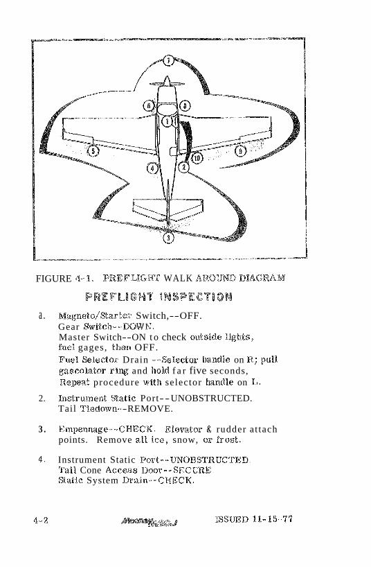
FIGURE 4-1, PREFUGRT WALK AROUND DUGRAM
a . ~ a g n e t o / % a s t e r Switch,--OFF. Gear Switch--NWN. Master Switch--ON t o check ot~tside lights, fuel gages, then OFF. Fuel &lector Drain --Selector h n d % e on R; pull gascolator ring and hold f a r five seconds, R e p a t procedure with selector h n d % e on La
2. Irastrument Static Port-- UNOBSTRUCTED. Tail Tiedown- -REMOVE.
3 . Empennage--@HECK. Elevator & rudder at tach points. Remove a%% ice, snow, o r f ro s t .
4- Instrument Static Port--mOBSTR%TCTED. Tail Cone Access Door- -SECmE. Static System Drain-- CHECK.

5. Wing Skins--CHECK. F lap and Attach Points--CHECK. Aileron and Attach Points--CHECK . Wing Tip Strobe and Navigation Light--CHECK. Remove a l l i c e , snow, or f r o s t .
6 . Left Wing Ideading Edge--CHECK. Pitot 'rube and Stall Switch Vane--WOWSTRUC%ED. Fuel Tank--CHECK QUANTITY:
A reduced fuel indicator is located in the f i l ler neck. T h i s indicator is used t o indicate use- ab le fuel capacity of 25 U. S. gal lons ,
Chock arad Tiedown--REMOVE. Left Main G e a r , Shock D i s c s and Tire--CHECK, Fuel Tank Sump Drain--SAMP%,E. Pi tot System Drain-- CHECK. Tank Vent-- IJNOBSTRUCTED. Fuel Selector Bra in Valve--CLOSED. BrVindslateld--C LEAN. Left Side Engine @ow% F a s t e n e r s- -SECURE.
'7. Propeller--CI3.%ECK for nickrs, c r a c k s and oil leakes, Forward Engine Components--@BIEGK s t a r t e r , a l t e rna tor belt , e te . Ram A i r Door--CHECK off and s e c u r e . Landing Light--@HECK. Nose Gear--CHECK t i r e ; cheek f o r towing damage. Shock Discs--CHECK. Chocks--REMOVE.
8. Right Side Engine Cowl Fasteners- -SECURE. Engine Oil Level--CHECK (Full f o r e d e n d e d flight). WindsiaieBd--C LIEAN. Fuel Tank Sump Drain--SAMPLE. Tank Vent- - UNOBSTRUCTED. Chock and Tiedown:-REMOVE. RigM Main Gear , Shock Discs and Tire--CHECK. Right Wing Leading Edge--CHECK.
ISSUED 111-15-7'7 4-3
6 . 7, 8 , 9,
a o . 31, 12. 13. 14 * 15. 16, 17. 18.
Fuel. Tank--CHECK QUANTITY.
A reduced fuel indicator i s located in the filler neck. This indicator is used t o indicate useable fuel capacity of 25 U. S. gallons.
Wing Skins - CHECK. Wing Tip Strobe (if installed) and Navigation Light - CHECK, Aileron and Attach Points - CHECK. Flap and Attach Points - CHECK. Remove all ice, snow, or frost.
Baggage Door - SECURE,
BEFORE STARTING CHECK Preflight Inspection - COMPLETE, Emergency Locator Transmitter - ARN (if installed). Seats, Seat Belts and Shoulder Harness (if ins-talled) - ADJUST AND SECURE, Fuel Selector Handle - SET for fuller tank, Parlcing Brake Contr~l - DEPRESS BRAKE PEDALS AND PULL ON. MagneJco/Starter Switch and Master Switches . - OFF, Radio Waster Switch - OFF. Cowl Flaps - OPEN (Control FULL Aft), Ram Air Control -- CLOSED, Landing Gear Switch - DOWN. Mixture Control - IDLE CUTOFF, Propeller - FORWARD HIGH RPM, Throttle - CLOSE (Full Aft), Electric Fuel Boost Pump - OFF, All External Lights - OFF, Cabin Heat - OFF. Wain Circuit Brealcer Panel - CHECK. Alternate Static Air Control - CHECK IN,
STARTitNC ENGINE
When startiny engine using an approved external power source (Auw. Power Cable Adapter is available from Mooney Aircraft Corporation) no special starting procedure is necessary, Use normal starting procedures be low,
REV D 3-7-84 ISSW,D 11-15-77

9, PO.
Propeller Control - FORWARD/HIGH RPM. Throttle Control - FORWARD l/4, Master Switch - ON. Mixture Control - FULL FORWARD, Electric Fuel Boost Pump Switch - ON TO ESTABLISH PRESSURE, THEN OFF. Mixture Control - FULL AFT (IDLE CUT-OFF) . Propeller Area - CLEAR. Magneto/Starter Switch - TURN AND PUSH TO START, RELEASE TO BOTH WHEN ENGINE STARTS. Mixture - MOVE SLOWLY AND SMOOTHLY TO RICH. Oil Pressure Gage - If minimum oil pressure not indicated within 30 seconds, STOP ENGINE, and determine trouble,
Cranking should be limited to 30 seconds, and several minutes allowed between crank- ing periods to permit the starter to cool.
1.1, Throttle - Set for LOO0 to 1200 K P M .
FLOODED E N G I N E CLEARING
ThsottLe-.-F'UEX. OPEN (FUEL, FORWARD), Mixture Control:--IDLE CUTOFF (FULL AFT). Elec t r ic Fuel Boost Pump--OFF1, Magneto/%arter Switch--turn t o "START'hnd PUSH forward. Throttle- -RETARD when engine s t a r t s . Mixture Control- - OPEN slowly to PULL RICH (FULL FORWARD). Oil P r e s s u r e Gage--If minimum oil p r e s s u r e not indicated within 30 seconds, STOP ENGINE, and de te rmine trouble.
BEFORE TAKEOFF Parking Brake--SET.
Controls--@HECK FREE A N D CORRECT MOVEMENT.
Radio Master--ON
Instruments and Radios-- CHECK AND SET A8 DESIRED.
REV D 3-7-84 ISSUED 11-15-77

5. Strobe Lights and Rotating Beacon--OW (if installed).
Annunciator Lights -- CHECK WITH PRESS-TO- TEST & THROTTLE RETARDED.
T r i m -- TAKEOFF SETTING. If forward CG s e t t r i m t o upper portion of band and to lower portion when a t aft CG.
THROTTLE -- 1900-2000 RPM,
Magnetos - - CHECK. Make magneto check a t 1900-2000 RPM, a s follows:
a . Magraeto/%arter Switcla - BOTH to R . Note RPM.
b e Magneto/%arter Switch - BOr6M. Allow t ime f o r plugs to c l ea r .
6. ~ l a g n e t o / ~ a r t e s Switch - &. Note R P M .
d o Magraeto/'Starter Switch - BOTH. The RPhT drop should not exceed 175 WPM on either magneto o r indicate g r e a t e r than a 50 WPM differen- t i a l between magnetos.
An absence of RPM drop may be an indication of faulty magneto ground- ing o r improper timing. If t h e r e is doubt concerning Ignition sys tem operation, R P M checks a t a leaner mixture sett ing or higher engine speed will usually confirm whether a deficiency exis ts .
P rope l l e r Control - CYCLE/RETURN TO HIGH B P M (full forward) .
Throt t le -. IDLE RPM.
Cabin Boor - LOCK.
Seat Belts - SECURE.
Wing F laps - TAKEOFF ( %So)
ISSUED 11-,15-77
TAKEOFF
Move the codrolls slowly and smooth$y. In particular, avoid rapid opening a d c%oeing of the t k o t t l e as the engine is equtppd with a counterweighted cranlnsmt and there is a wml- bility of detuniw the counterweights and over- s p e d i q with subsquen t e a i n e &mage.
R o p e r full throttle ewine operatibn should be checked ear ly in the takeoff roll. Any significant indication of rough or sluggish engine response is reason t a discontinue the takeoff.
When takeoff must be made over a gravel surface, it is important that the throttle be applied s%ow%y. This will. allow the aircran to s tar t r o l l i q before a high RPM is devel- sped, and gravel or ~ Q O S ~ material will be blown back from tlae prop area instead of being pulled into it.
TAKEOFF (Normal)
1, Electric Fuel Boost Pump - QN at start of takeoff roll ,
2 . Power - FUEL THROTTLE and 2780 RPM.
3 , Aircraft Attitude - WFT NOSE WHEEL AT 7 1 M P H (62 KTS.) IAS.
4 . Climb Speed - 83 MPN (71 KTS) IAS.
5. Landing Gea r - RETRACT IN CLIMB BEFORE ATTAINING AN AIRSPEED OF 120 MPH (104 KTS) IAS.
6 , Wing Flaps - RETRACT I N CLIMB.
7. Electric Ftae% Boost Pump - OFF, CHECK PRESSURE.
TAKEOFF (Obstacle Clearance)
1. Electric Fuel Boost m m p - ON at start of takeoff roll.
2. Power - FULL TEHROTTLE AND 2700 RPM-
3 , Aircraft Attitude - WFT NOSE WHEEL AT 71 MPH (62 KTS. ) IAS.
4, Climb Speed - 76 MPH (66 KT'S. ) IAS until clear ~f obstacle, then accelerate to 105 to 115 MPH (91. Cs 100'mS.) IAS.
5. h n d i n g Gear - RETRACT IN CLIMB AFTER C LEARING OBSTAG: LE .
6. &%ring Flaps - RETRACT AFTER CLEARING OBSTACLE.
7. Electric Fuel Boost Pump - OFF, CHECK P R E S S m E ,
CLIMB
LIMB (Nor naai)
1. TBarottRe - 28" H 6 MANIFOm PRESSURE.
3. Propeller - 2608 RPM.
3 Mixture - LEAN FOR SMOOTH OPERATION.
4, Cowl Flaps - FULL OPEN.
5. Airspeed- 105-115 MPH(91-10QKTS).
,.. Ram A i r - OPEN AFTER ENTERING CLEAR AIR.

CLIMB (Best Rate)
1. Power - FULL THROTTLE & 2'700 RPM,
2 . Mixture - LEAN FOR SMOOTH OPERATION.
3 , @ow% Flaps - FUEL OPEN.
4 . Airspeed - I01 MPM (88 KT'S) IAS a t Sea Level decreasing t o 94 MPH (82 KTS) IAS a t %0,000 Ft .
5. Ram Air -ON AFTER ENTERING CLEAR AIR.
Manifold p re s su re wi l l d rop with increasing altitude a t any throttle setting. Power can be res tored by gradually opening the throt t le .
To Increase ~ex?ormance<ak ftuli throt t le , pull tho Ram A i r control aft (.&..an A i r ON position) allowing inducll.on a i r to bypass the air filter and Iracseas6 manifold p re s su re .
Turn r a m a i r off i f encountering icing conditions. Do aaot fly a i rc raf t into known icing conditions. Using un- filtered induction a i r when flying in snow or other IFR conditions can be hazardous. Snow can accunaulate in the fuel injector impact tubes, o r moisture can f r eeze in the inlet passages under icing conditions to cause loss of power. If snow o r icing conditions were en- countered DO NU% T U R N RAM AIR ON AGAIN when entering clear a i r until a s su red that a l l i ce has melted f rom the a i rc raf t . Do not use r a m a i r in visibly dusty a i r .
After establishing climb power and tr imming the a i r c r a f t for climb, check t o insure that all contro%s, switciaes, and instruments a r e s e t and functioning properly.
REVISION A
Upon reaching c ru i se altitude, allow accelerat ion t o c ru ise a i r speed , then t r i m the a i rc raf t for level flight, reduce manifold p re s su re and R P M to des i red c ru i se power, and close the cowl flaps. The cowl f laps should be partially opened (control pulled aft approxilraately t h r e e inches) i f n eces sa ry , to maintain the oil and cylinder head t empera tu re s within the normal operating range.
When cruising a t 7'5 percent power or l e s s , lean the mixture after c r u i s e power is established in accor- dance with one of the following methods:
A . Leaning using exhaust gas temperature gage (EGT) (if installed) 1, Lean the mixture until t empera ture peaks on
the EGT indicator.
ECONOMY CRUISE - Enrich mixture (push mixture ver forward) until the EGT indicator
- drops &A F r more below peak. i q ~ ~ - % E S T -, POWER MIXTURE
(\. ..--,,
Best power mixture will resu l t in a speed inc rease , an increase i n fuel flow and a reduction in range.
2. Changes i n altitude and power set t ings r equ i r e t h e peak EGT to be rechecked and the mixture r e - s e t .
B. Leaning without exhaust gas temperature gage (EGT)
1. Slowly move mixture control lever aft f rom "Full Richqs position toward lean position.
2. Continue leaning until slight l a s s of power is noted ( loss of power may or may not be accom- panied by roughness).
ISSUED 1%-15-7'7

3, Elwtcka until engine runs smoothly and power i s r ega ined
When increasing power always re turn m i d w e to full r ich, then increase RPMbefore increasing manifold pressure ; when decreasing power decrease manifold p r e s s u e p e f o r e r e d u c i x RPM. Always stay within the established operating l imits , and always operate the con&ro%s 8%0w$y and smoothly.
DESCENT
1 . Mkttare - R%CH/OR LEAN FOR SMOOTH OPERATION.
2 , Power - A S DEWRED.
Avoid continuous operation between 15061 and 1958 RPM with power setttxags below 15"Ag. manifold preseaare,
Exercise caution with power settings below 15" Hg manifold pressure a t a i r - speeds between 80-130 M P B (70-113 Kts. $AS t o preclude continuous operation i n t be 1508-1950'RPM res t r ic ted range.
3, Cowl Flaps - CLOSED (control full forward),
BEFORE LANDING 1. Seats, Seat Belts and Shoulder Harnesses - ADJUST
AND SECURE,
2, h n d i w Gear - EXTEND BELOW 155 M P N (135 KTS. ) 8 %AS.
3 . Mhture Control - FULL RICH,
4, Fuel Selector - RIGHT OR LEFT (Fullest tank),
5. PropelRer Control - HIGH RPM.
6 . Wing Flaps - FULL DOWN (33') BE LOW 132 MPH (115 KTS) %ASo
REVISION B 4-11
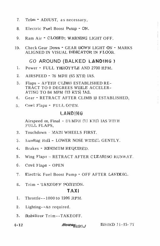
7. T r i m - ADJUST, a s necessary ,
8. Electr ic Fuel Boost Pump - ON.
Ram Air - CLOSED; WARMNG LIGHT OFF.
Check Gear Down - GEAR DOWN LIGHT ON - MARKS ALIGNED IN VISUAL ImIGATOR IN F L W R .
G O AROUND (BALKED LANDING 1 Power - FULL THROTTLE AND 2700 RPM,
AIRSPEED - 75 M P H (65 KT$) IAS.
Flaps .- AFTER CLIMB ESTABLISHED RE- TRACT TO 0 DEGREES WHILE ACCELER- ATING TO 84 MPM (73 KTS) %AS. G e a r - RETRACT AFTER CLIMB IS ESTABLISHED,
Cow% Flaps - FULL OPEN,
LANDING Airspeed on, Final - 8% M P H (71 KTS) IAS WITH PTJLL FLAPS,
Touchdown MAIN WHEELS FIRST.
Landing Roll - LOWER NOSE WkIEEL GENTLY.
Brakes - M N I M U M REQURED.
Wing Flaps -. RETRACT AFTER C L E m I N G R W W A Y .
Cow% Flaps - OPEN
Electr ic Fuel Boost Pump - OFF AFTER LANIDI[NG.
Trim - TAmOFW" POS%TION.
TAXD Throttle--1000 to 1200 RPM.
Lighting- - A s required.
Sab i l i ze r T r i m - -TAKEOFF.
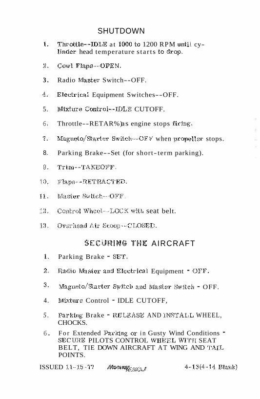
SHUTDOWN
1 , Tkott%e--IDLE a t I000 to 1200 RPM ~11til cy- linder head temperature s t a r t s to dr op.
3 . Radio Master Switch--OFF.
4. Electrical Equipment Switches--OFF.
5. MMure Control- -IDLE CUTOFF.
6 Throttle--RETAR%) as engine stops firing.
7. ~ a g n e t o / B a r t e r Switch--OFF when propeller stops.
8. Parking Brake-- Set (for short- term parking).
' 2 Control* Wheel--1,OCK witla seat belt.
SECURING THE AIRCRAFT
1, Parking Brake - SET*
2 Radio m s t e r and EBectrica%. Equipment - OFF'.
3 , ~ a g n e t o / % a r t e r Switch and Master Switch - OFF.
4. M b t u r e Control - IDLE CUTOFF,
5 . Pariring Brake - RELEASE AND INSTALIuI WHEEL, CHOCKS.
6. F o r Extended Parking or i n Gusty Wind Conditions - SECURE PILOTS CONTROL WHEEL WITH SEAT BELT, TIE DOWN AIRCRAFT AT WING AND TAIL POINTS.
ISSUED 18-15-77 4-P3(4-14 Bkalk)

SECTION V . PERFORMANCE TABLE OF COBTENTS
INTRODUCTION . . . . . . . . . . . . . . . . . 5-3 . . . . . . . . . . . . . . . . . HOISE UMTATIONS 5-3
. . . . . . . . . . . . . A &TI% UDE CQNVERSIQN S - r
. . . . . . . . . . . . AIRSPEEDCALIBRATION 5-7 NORMAL STATIC SYSTEM . Flaps & (;ear Up . . . 5-7 NORMAL STATIC SYSTEM . Flaps & Gear Down . . 5-8 ALTERNA'TE STATIC SYSTEM . . . . . . . . . . 5-9
ALTIMETER CORREG'I'IBWS . . . . . . . . . . . NORMAL, STATIC SYS'J'EM . F'iaps & Gear Up . . . 15- 10 NORMAL STATIC SYSTEM . Flaps & Gear Down . . 5-11 ALTERNATE srra%mc SYSTEM . . . . . . . . . 5-13
. . . . . . . . . . . . . . . . . STAIJL SPEEDS 5-13
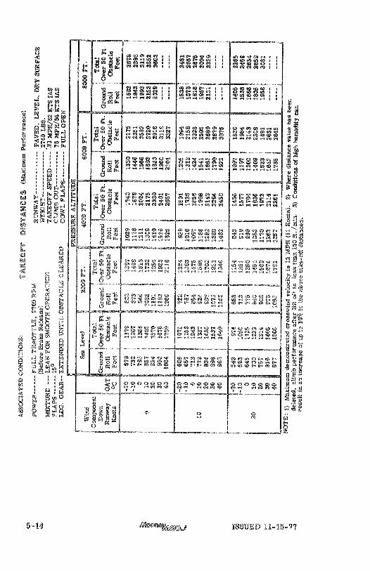
TAKEOFF DISTANCES MAXIMUM PERFORMANCE . 5- 14
TAKEOFF DISTANCES NORmX.. . . . . . . . . 5-15
CLIMB PERFORMANCE . . . . . . . . s o - o 5-18
. . . . . . . . TIME. FUEL & DISTANCE TO C-LIMB 5-17
. . . . CRUISE. RANGE AND ENDURANCE @HARFFS 5-19 . . . . . . . . . . . . . . . . BEST ECONOMY 5-20
. . . . . . . . . . . . . . . . . BEST POWER 5-28
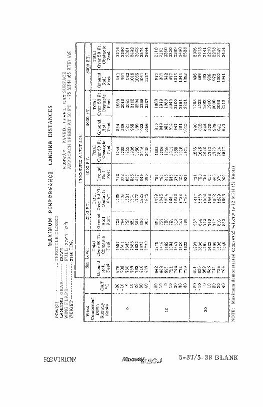
LANDING DISTANCES . . . . . . . a , . . - . . 5-30 . . . . NQRMAL LANDING * . * . a ~ o a 5-36
MAXIMUM PERFORMANCE . . . s . . . . . . . 5-37
VISION B 5- 1/5-22 BLANK

A l l performance tables and graphs a r e grouped In t h i s section of the manual for quick and easy reference. The information i s presented t o show performance that may be expected from the a i rc raf t , and t o ass i s t you in planning your flights with reasonable detail, and accur- acy. All data has been compiled from both calculations and actual tes t flights with the aircraf t and engine in good operating condition while using average piloting techniques. The cru ise performance data makes no allowance for variables present with a specific a i rc raf t or for wind and navigation e r r o r s . In using th is data , allowances must be made for actual conditions.
h carefully detailed and analyzed flight plan will yield maximum efficiency. After making a flight plan based on est imates taken from the data in this section, you should check your actual performance and note the difference between your forecast conditions and actual flight performance s o that your future estimates may be more aeetnrate.
The eer t s ica ted Noise Level fo r the Model M289 at ,2240 pounds m a i m u r n weight is 74 dB(A), No determim-tion has been made by the Federa l Aviation Administratioaa that the noise levels of %his airplane a r e oh: should be acceptable o r u c e e p t a b l e fo r operation at, into, o r o d d any a i r p o d ,
REVISION B

ALTITUDE CONVERSION TAS = @AS x 1/m

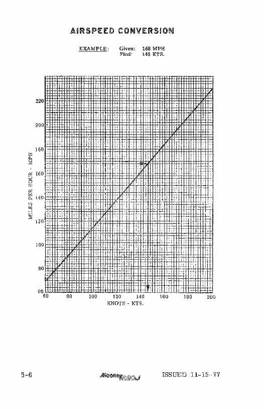
E;XIBMPEE: Given: 168 MPH Find: 146 BCRS.
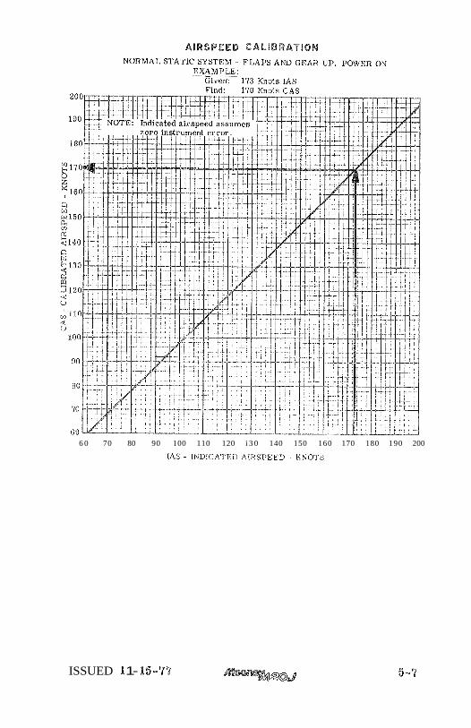
AIRSPEED CALlBRATsON
6 0 70 80 90 100 110 120 i 3 0 140 150 160 170 180 190 200
IAS - INI1ICA'T'F:I) AIIISPFED - ICNO'I'S
ISSUED X 1- 15-77
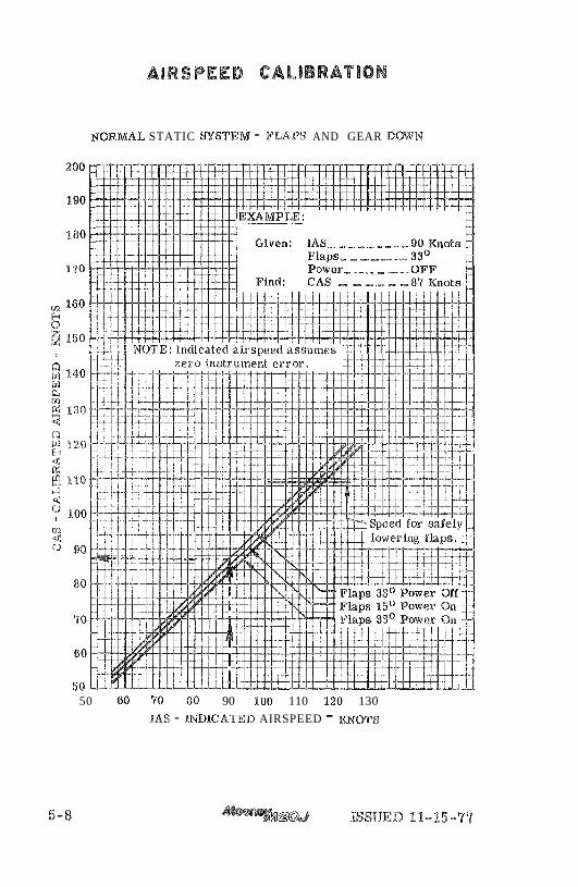
AIRSPEED CALIBRATION
NORMAL STATIC =S%EIVT - FLAPS AND GEAR Dm'N
50 60 90 80 90 100 110 I20 130
IAS - INDhCATED AIRSPEED - m m S
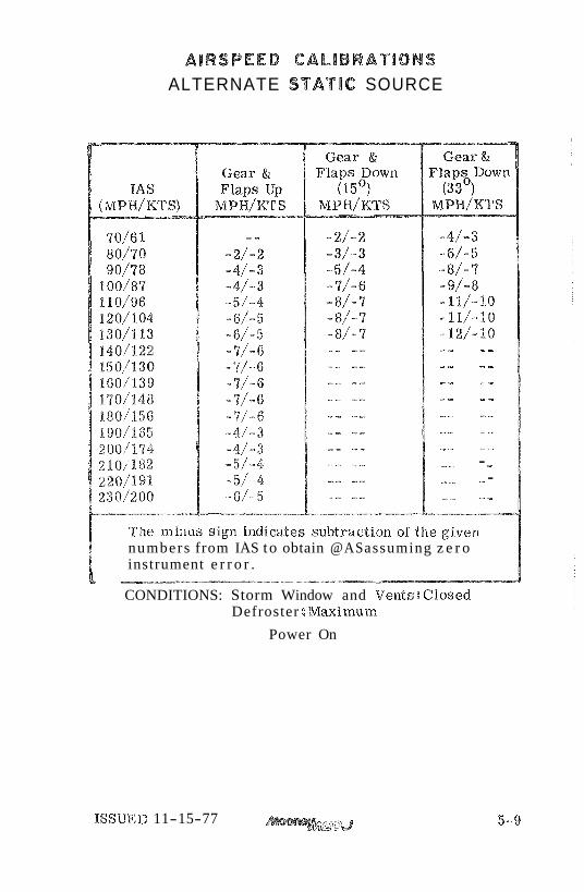
AIRSPEED CALIBRATIONS ALTERNATE STATIC SOURCE
- - - - "" - - .." -.- - -
- - "~ - -. 7. .-, - - -. .~*.- ,.... %
-" e,, - -" <-. -- - - .-- ---
~-.--- --.-
numbers from IAS to obtain @AS assuming z e r o instrument e r r o r .
L - CONDITIONS: Storm Window and Vents:@Iosed
Defroster : M a i m u r n
Power On
ISSUED 11-15-77 aJ

ISSUED 11-15-77
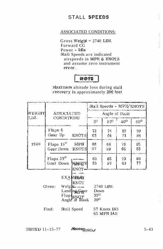
STALL SPEEDS
ASSOCIATED CONDITIONS:
Gross WeigM =: 2740 LBS. Forward CG Power - Idle S a l l Speeds a r e indicated
airspeeds in MPH & mQT$ and assume zero instrument e r r o r .
Maimurn altitude loss during stall recovery is approximately 290 feet
-----.
Flaps k2
[; Gear Up ~ O T S
Flaps 15' M P H GearDown Bg$r%OP$E
Flaps 33' Gear Down KNOTS
EXAMPLE:
Given: Weight 2740 LBS. Landing Gear Down Flaps 3 3 O Angle of Bank 2O0
Find: Stall. Speed 57 Knots IAS 65 MPH %AS
ISSUED 11-15-77 5-43

ISSUED 11-15-77
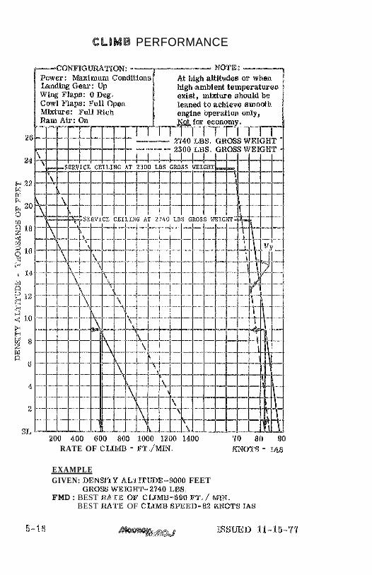
CLIMB PERFORMANCE
RATE OF CLIMB - PT./MLN. ma$$ - %A8
EXAMPLE GIVEN: D E N S T Y A L % % T m E - 9 0 0 0 FEET
G R O S WEIGHT- 2940 LBS. FMD: BEST RATE OF CWMB-590 FT./ MM.
BEST RATE OF CLIMB $PEED-$% KXdBTS %A8
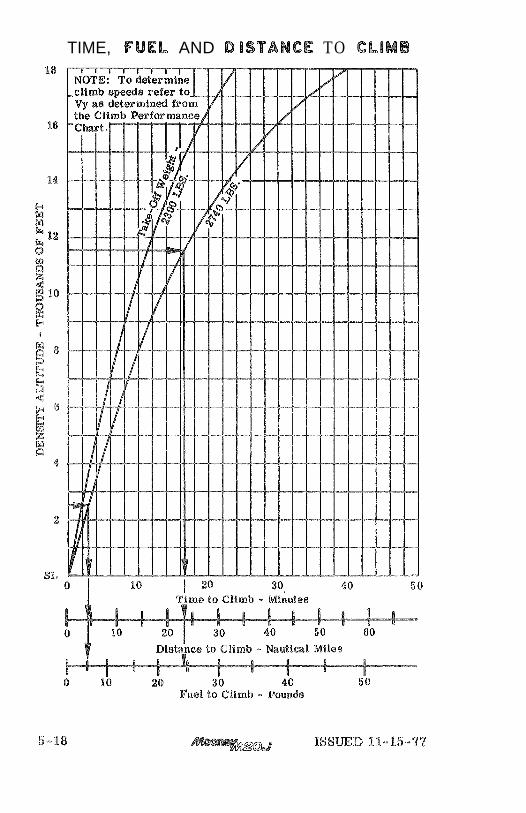
TIME, FUEL AND DlSTANCE TO CL lMB
Associated Conditions for the Time, Fuel and Distance to Climb graph on the following page:
Climb Speed : Vy from Climb Performance graph on the preceeding page. Power: 2700 RPM, Full T k o t t l e Mhtur e : Full Rich Ram Air : On Cowl Flaps: Full Open Landing Gear: Up Wing Flaps: Up Fuel Density 6. O Lbs. / G ~ R .
NOTE:
1 , Distances shown are based osa zero wind. 2. Add 9 LBSr of fuel far startp taxi aaad takceelf.
E m M P L E : Given: Initial Deaasity Altitude 2,500 Ft.
Final Density Altitude I f , 500 Ft. Takeoff Weight - 2240 Lbs.
Find: Time to Climb ( 316.5 - 3. Q) 13.5 Minutes Distance to Climb (23. 5 - 4.5) 19. Q Naut, Mi. Fuel to Climb (24.5 - 5.0) 19.5 Lbs.
ISSUED 11-15-77
TIME, FUEL AND OlSTANCE TO CLIMB
GRUlSE & RANGE DATA CONDlTlONS
1. A%%. Cruise and -we Data tables allow for: warmup, taxi, take-off, climb at m a . power a t the best r a t e of climb speed (Vy) t o cruise altitude; a cruise to destination at the specified power and mixture setting; and a 445-minute fuel r e se rve at the same altitude and power setting. The data is a lso based on 64 U. S. gallons of usable fuel, standard atmosphere, and no wind.
To obtain the performance shown by the Cruise and Range Data tables on non-standard days, in- c rease or decrease the manifold presstare approxi- mately - 4 " Hg for each 1Io0C variation in outside, air temper attare. Increase manifold pressure for air temperatures above standard and decrease manifold pressure for a i r temperatures lower than standard.
3. During winter operations when snow and i ce are likely to be present on the taxaxgi and runway s%~sfaces the inboard landing gear doors shota%d be removed. Aeeumea%alios% of ice and snow could prevent Banding gear operation. E the inboard landing gear doors have been removed a decrease in cruise speed and range can be expected and sRaould be considered in preflight planning. To be consermtive the following figures should be used:
a. Decrease t rue airspeed at normal cruise power setting by approximately 5 lmots.
b. Decreased range may be a s much as 50 nautical miles for 64 gallon fuel capacity.
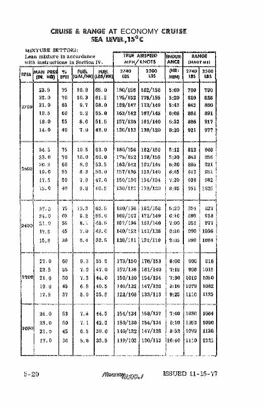
CRUISE & MNGE AT ECONOMY CRUlSE sw LWEL, I S"C
RpM py PI? % ( NB I FUEL (iW HO) BPH (OAB/B(W) (bU/%lsR)

CRUISE L RANGE AT ECONOMY CRUlSE 2000 FT, 1 9 1 ~ ~
ISSUED 11-15-77 5-21
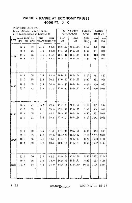
CRUlSE L RANGE AT ECONOMY CRUISE 4000 FT, 7* C
5-22 ISSUED 11-15-77
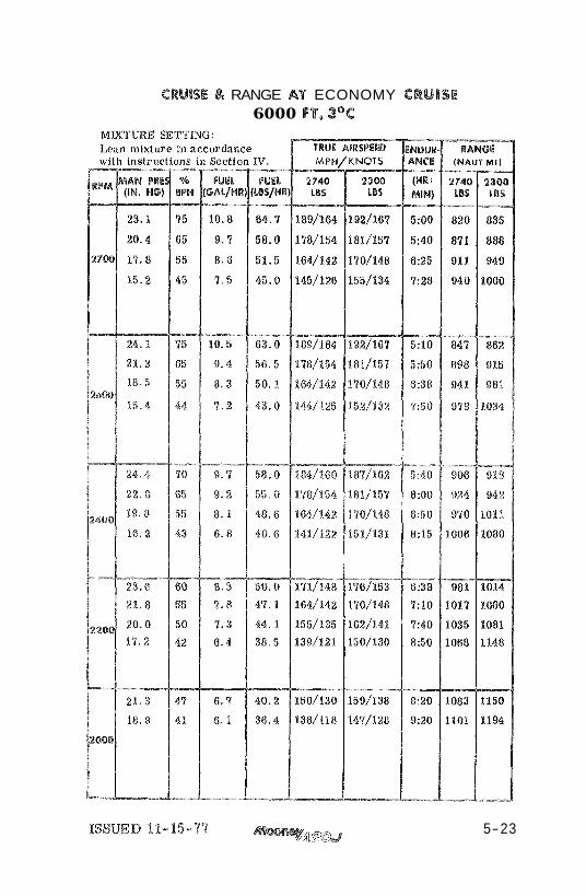
CRUISE 8 RANGE AT ECONOMY CRUISE 6000 F t , 3'C
ISSUED 18-15-77 5-23
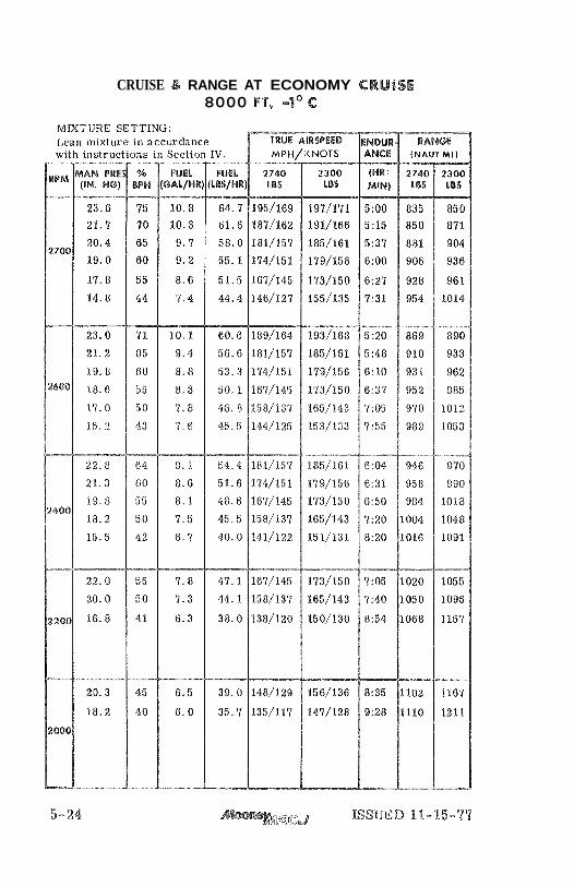
CRUISE L RANGE AT ECONOMY CRUISE 8000 FT, -1' C
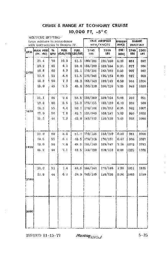
CRUISE 8% RANGE AT ECONOMY CRUlSE

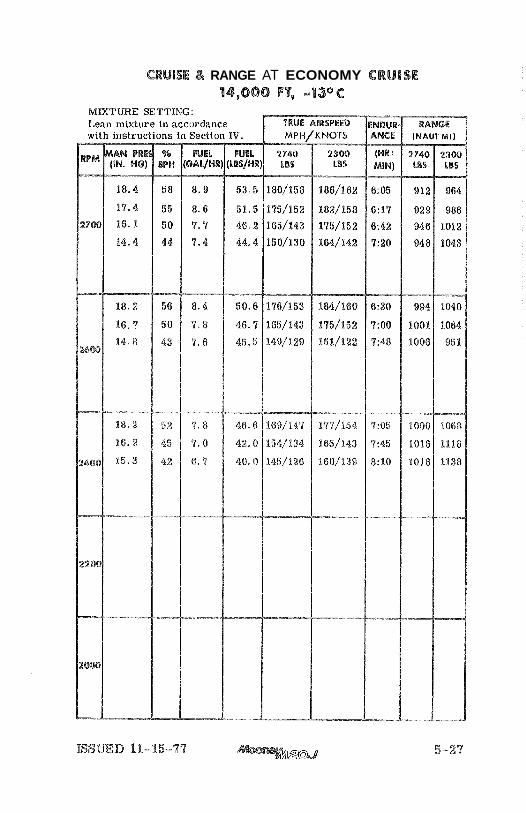
CRUISE L RANGE AT ECONOMY CRUISE 14,060 FT9 -13°C

CRUISE L RANGE AT BEST POWER
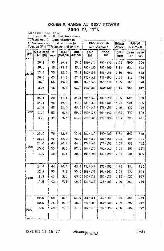
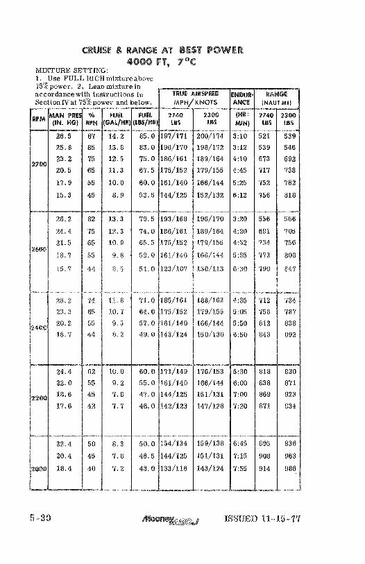
MIXTURE SETTING: SEA LEVEL, 15°C
1. Use FULL RICH mixture above 75% power. 2 . Lean mixture in accordance with instructions in Section TV at 75% power and below.
5-28 ISSUED 11-15-77
CRUISE L RANGE AT BEST POWER
MIXTURE SETTING: 2000 FT, "ill°C
1. U s e FUEL RICH mixture above
ISSUED 11-15-77 5-29

CRUlSE & RANGE AT BEST POWER
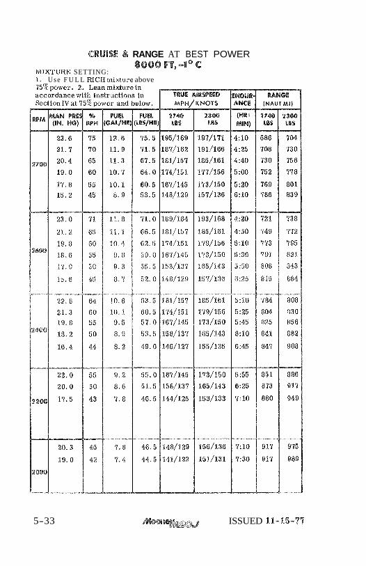
MIXTURE SETTING: 8000 FT, -1" C
1. U s e F U L L RICH mixture above
5-33 ISSUED 11-15-77
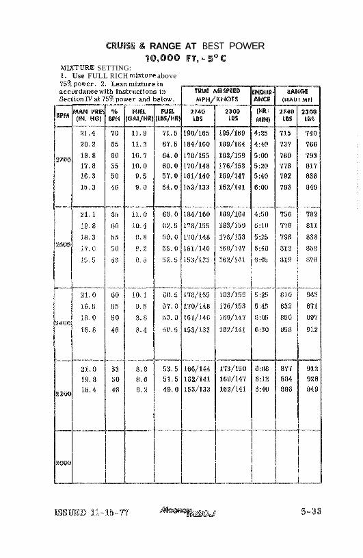
CRUlSE 4% RANGE AT BEST POWER 10,000 PT, - SO c
MIXTURE SETTING: I. Use FULL RICH mixture above

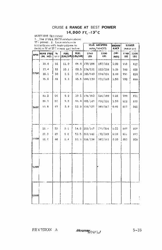
CRUISE L RANGE AT BEST POWER
MA
XIM
UM
P
ER
FO
RM
AN
CE
L
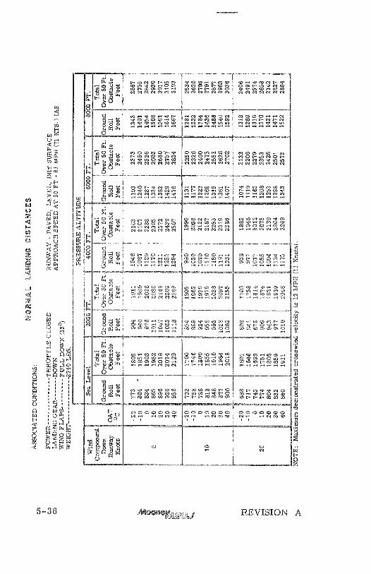
AN
DIN
G D
IST
AN
CE
S
P0V
;ER
--
----
----
----
-- THROTTLE CLOSED
LA
ND
ING
GEAR--
----
-- D
OA
"A'
WIN
G FLAPS--
------
--- FULL D
OW
N (
33')
WE
IGH
T --.----.--------
27
40
ii3
S.
RU
NW
AY
- P
AV
ED
. 1,
EV
FI.
. D
RY
SURFACE
APPROACH SPEED AT 50 FT
- 75 Ml'H
(65
KT
S) IAS
NO
TE
: M
axim
um
de
mo
nst
rate
d c
ross
wln
ci v
elo
cliy
js
i2 M
PH
(1
1 K
no
ts)

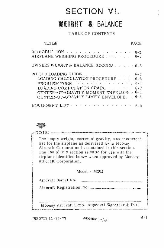
SECTION VI.
W E I G H T & BALANCE TABLE O F CONTENTS
TIT LE PACE
. . . . . . . . . . . . . . . INTRODUCTION 6 - 2 AIRPLANE WEIGHING PROCEDURE . . . . . . 6-3
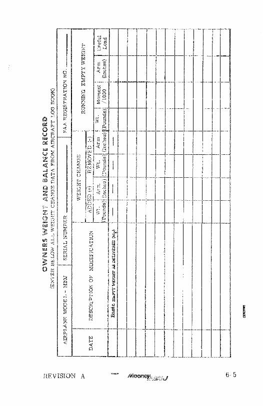
OWNERS WEIGHT & BALANCE RECORD . . . . 6-5
. . . . . . . . . . . . P%EOF%'S LOADING GUIDE 6- 6 LOADING CALCUUTION PROCEDURE . . . . 6-6 PROBLEMFORM 0 - - 0 = o . * . . 6 - 7 LOADING COMPUTATI6N G-PH . . . . . 6-7 CENTE13-OF-GRAV%'rY MOMENT ENVELOPE * 6-8 CENrFER-OF-GRAVITY LIMITS ENVELOPE . 6-8
. . . . . . . . . . . . . . EQIJKPMENT LIST 6-9
'a'2ae empty weight, center of gravi ty, and equipment l is t for the airplane as delivered f r o m Moonel. Aircraft Corporation is contained in t h i s section. The use of t h i s section is valid for rase w i t h t he airplane identified beiow whela approved by Woonej; Aircra.$t Corporation,
Model. - M20J
A i ~ c r a f t Serial No.
a$ircraf$ Registration NO. --p

This section describes tkae procedure for ca l cu i a t i x loaded a i r c r a f t weight and moment for various flight operations. In addition, procedures a r e provided for calcuhting the empty weight and mo- ment of the aircraft when the removal or addition of equipment resu l t s in changes t o the empty weight and center 0% gravity. A comprehensive list of a l l Mooney equipment available for th i s airplane i s included in t h i s section, Only those i t ems checked (X) were in- s ta l led a t Mooney and a r e included in the empty weight-and-balasace data.
T h e F A A charges you, the a i rc raf t owner and pilot, with the responsibility of properly loading your a i r - c ra f t for sa fe flight* Data presented in this section will enable you to c a r r y out this responsibility and in su re that your airplane is loaded t o operate within tile prescribed weight and center-of-gravity Xirnitatioe~s.
At the t ime of delivery, Maoney Aircraf t Corporatioxl p r o d d e s the empty weight and center of gravity data for tkae computation of individual loadings. (The empty weight and C. G . (gear e&exldad) as delivered from the factory is tabulated ow page 6-5 when this nnaarual i s supplied wi th the a i rc raf t from &he factory. )
FAA regulations also r equ i r e that any ckraixe in tkae original equipment a f fec t iw the empty weight and center of gravity be record& in tire Aircraf t Log Book, A convenient form for maintaining a permanent record of a$% such changes is provided on page 6-5. This form, if properly maintained, w i l l enable you t o determine the cur ren t weight-and-balanee s ta tus of the airplane for load schedu%ix . The weight-and-balance data en tered as your a i rc raf t 'left the factory, plus the r e c o r d you maintain on page 6-5, is a l l of the data needed to compute loading schedules.
The m a i m u m certificated g r o s s weight for the Model M20J under a%% operating conditions is 2740 pounds, m x i m u m useful load is determined by sub- t rac t ing the corrected a i r c r a f t empty weight from i t s
maximum gross weight. The aircraft must be operated strictly within the limits of the Center-of -Gravity Moment Envelope shown on page 6-8.
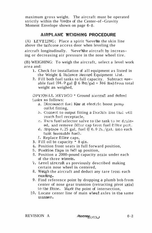
AIRPLANE WElGHlNC PROCEDURE (A) LEVELING: Place a spirit %eve% on the skin line above the tailcone access door when leveling the
aircraft longitudinally. %eve% the aircraft by increas- ing or decreasing a i r pressure in the nose wheel t i re .
(B) WEIGHING: To weigh the aircraft , select a level work a r e a and:
1, Check fo r installation of a l l equipment a s listed in the Weight & Balance Record Equipment List-
2, Fil l both fuel tanks to full capacity. Subtract use- able fuel (64,O gal @ 6 l b ~ / ~ a 1 = 384 lbs)ifrom total weight as weighed,
QPTIONAL METHOD - Ground a i r c r d t and defuel tanks as follows:
a. Disconnect fuel Kine at e l e d r i c boost pamp or~tlet fitting,
b, Connect to output fitting a flexible line that wi l l reach fuel receptacle,
c. Turn f ue l selector salve to the tank to be drai.n- ed, a d remove fi l ler cap from fuel f i l le r pox?,
d, m p l a c e I. 25 gal, fuel @ 6.0 &*/gal, into each tank (unaasab?.e fuel),
f, Replace f i l ler caps, 3 . Fill oil to capacity - 8 qts, 4, Position front seats in full forward position, 5, Position %Laps in full up position, 6, Position a 2000-pound capacity scale under each
of the three wheels, '7, Level aircraft a s previously described making
certain nose wheel is centered, 8, Weigh the aircraft and deduct any t a re f rom each
reading . 9, Find reference point by dropping a plumb bolo from
center of nose gear trunnion (retracting pivot =is) to the f l o ~ r . Mark the point of intersection,
10. Locate center line of main wheel axles in the, same m m n e r .
REVISION A

11. Measure the horizontal distance f rom the reference point t o main wheel axle center line, Measure horizontal distance from center line of nose wheel axle to center line of main wheel axles.
12. Record weights and measurements , and compute basic weight and CG a s follows:
R E F POINT
- ~ < ~ . ~ ~ ' - , ~ - ~ " > ~ ~ ~ L - - - - . ~ 3 a ~ v ~ - ~ ~ - -
a . CG Forward of Main Wheels:
LBS. -- IN. ___ Weight of Nose DZE,iiGT&zZ- ' LBS.
Total Weight IN.
Main and Nose Wheel of Aircraf t CG Forward
Axle C e n t e r s of Main Wheels
b. CG Aft of Datum (Station 0):
IN, - 5 I N N - 1N. = Dlstance f rom
IN. Distance f r o m Center Result of
Nose Gear Trunian CG (FUS. STA.)
Nose G e a r Trunlon t o Computation t o Datum
Distance Aft Center of Main Wheel Above of Datum. Axles (Horizontal) (Empty Weight CG)
0.- vRB Constant (8‘-MI
6-4 $52- J REVISION A
REVISION A -
22. ' P ~ J 6-5

PILOT'S LOADING GUlDE
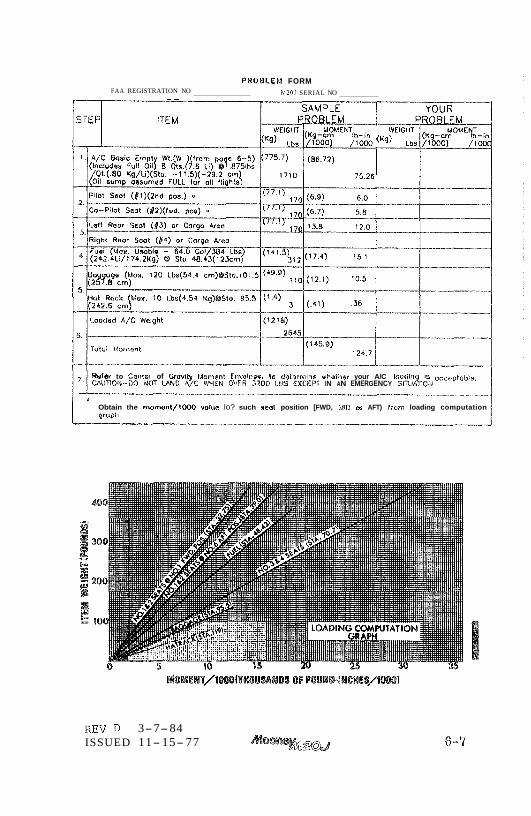
LOADING CALCULATION PROCEDURE
Proper loading of the aircraft i s essential! for maximum flight performance and safety. This section will assist you in determining whether the aircraft loading schedule i s within the approved weight and center-of-gravity limits.
To figme a n actual loading problem for your a i rcraf t , proceed a s follows:
Step I. Refer to the latest entry on page 6-5 for the cur- rent empty weight and momento NOTE: Since the engine oil is normally kept a t the full! level, use the oil weight and moment figures shown in the sample problems a s con- stants in calculating a l l loading problems.
Step 2, Note the pilotgs weight and the position his seat will occupy in %lighto Find this weight on the %eft scale of the Loading Computation Graph (page 6-7') and cross the graph horizontal%y to the point representing the pilot's seat position be- tween the FWD and AFT position lines on the graph for 8% and $12 seats, When this point i s located, drop down to the bottom scale to find the value of the moment/1000 due to the pilot's weight and seat position,
Repeat the procedure for the copilpt and enter these weights and rnomelat/1000 values in the proper subcolumns in the Problem Form on page 6-7'.
Step 3 , Proceed a s in Step 2 to account for the passen-- ge r s in seats 3 and 4. Enter the weight and value of mornent/1000 in the proper columns.
Step 4, Again proceed a s in 8 e p 2 to account for the amount of fuel carried, and enter the weight and moment/1000 values in the proper columnso
PROBLEM FORM FAA REGISTRATION NO
- - h120J SERIAL NO
Refer to Center of Grwity Irloment Envrlepe to determine whathsr your A/C laodin is occeptnbio. CWUIIORI-DO NOT MD A/C MEN ww J Z ~ O IDS EXCEPT IN AN EMERGENCY SITUA~ON.
Obtain the mam@nl/lOOO vatus lo? such aeot position [FWD, UID ar AFT) Fvarn loading computation graph.
REV 3-7-84 ISSUED 11- 15- 77
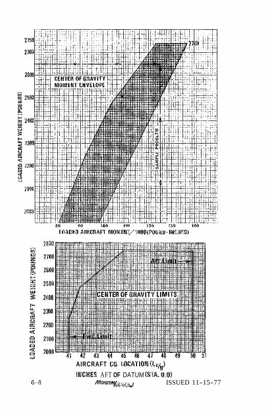
AIRCRAFT CG LBCATION(Lyg)
lMCMES AFT OF DATUM (SM. 0.0) ISSUED 11-15-77
Wep 5. Once more proceed as in Step 2 t o account for the baggage t o be ca r r i ed and enter the f igures in the proper columns.
Step 6, Total the weight columns. This total must be 2940 pounds o r l e s s . Total the ~ o m e n t / 1 0 0 0 column. Do not forget t o subtract negative numbers,
Step '7. Refer t o the Center-of-Gravity Moment Enve- lope (page 6-8). Locate the loaded weight of your airplane on the %eft sca le of the graph and t r a c e a line horizontally t o the right. Locate the total moment/1000 value for your airplane on the bottom sca le of the graph and t r ace a line vertically above th is point until the horizon- t a l line for weight 6s intersected. If the point of intersection is within the stladed a r e a , your a i rc raf t loading i s acceptable. If the point of intersect ion fal ls outside the shaded a r e a , you must r ea r r ange the load before takeoff.
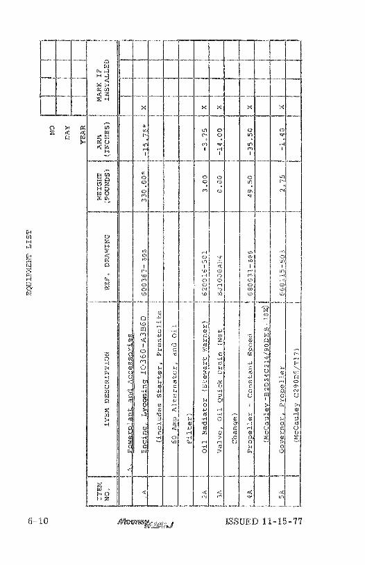
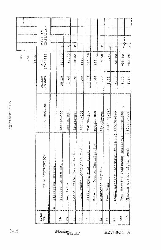
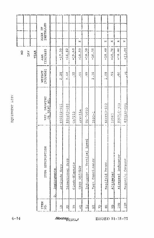
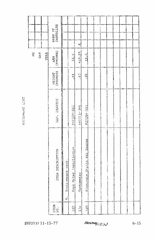
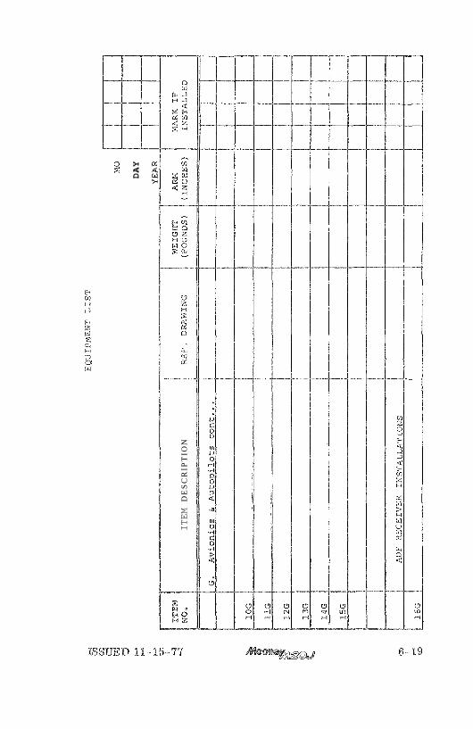
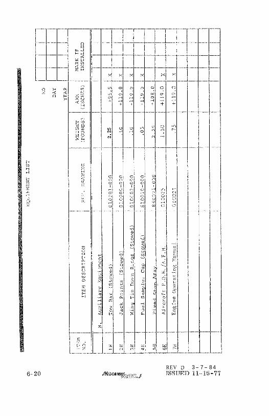
EQUIPMENT LIST The following Equipment L i s t is a listing of all i tems approved at the t ime of peablication for the Mooney M20,
Only- those ' i t ems having an X in the "Mark I f InsCaR%edM column and dated were installed a t Muoney.
E additional equipment is to be installed it must be done in accordance with the re ference drawing or a separate F A A approval.
Positive a r m s a r e dis tances aft of the airplane datum. Negative a r m s a r e dis tances forward of the airplane datum.
Asterislss (*) after the i tem weight and a r m indi- cate complete assembly installations. Some major components of the assembly a r e listed and indented ora the lines following. The summation of the major components will not necessari ly equal the complete assembly installation.
'SUED 11-15-77 a,' J


ISSUED 11-15-77 6- 15

6- 16 ISSUED 11- 15- '8%

ISSUED 11-15-77 g > ~ d iJ ii
6- 1's

ISSUED 11- 15-77
DAY
ITEM
DE
SC
RIP
TIO
N
REV D 3- 7- 8 4 ISSUED 11-15-77
AlRPLAlE & SYSTEMS DESCRIPTION TABLE OF CONTENTS
TITLE PAGE
POWER BLAm . . . . . . . . . . . . . . . 7-4
. . . . . . . . . . . . ENGINE CONTROLS 7-4
. . . . . . . . . . . . IGNITION SYSTEM 7-5 . . . . . . . . . . . . . . FUEL SYSTEM 7-8
. . . . . . . . . . . . . . . OIL mSTBM 7-8 . . . . . . . . . . . . . ENGINE G W L I N G 7-8 . . . . . . . . . . . . . VACUUM =STEM 7-8
. . . . . . . . . . . . . . . PROPELLER 7-8
BWGBT PANEL & CONTROLS PAMLURIZATION. . . . . . . . . . . . . c . 5-9 PLIGHT INSTRUMENTS & CONTROLS . . . . . 7-9 ENGINE INSTRUMENTS B CONTROM . . . . . 7-14 m S C E LLANEOUS INSTRUmNTB. CONTROL9
. . . . . . . . . . . . . . . . &INDICATORS 7-18 . . . . . . A N W ~ C I A T O R AND PANEL 7-20
. . . . . . . . . . . . . . . . . FLJGBT CQNTROU 7-22
. . . . . . . . . PRIMARY FUCHT CONTRBM 7-22 . . . . . . . . . . . . . . . . TRIM CONTROW 9-22 . . . . . . . . . . . . . WING F M B GOmROM 7-22
. . . . . . . . . . . . . . PITOT-STATIC SYSTEM 7-22
. . . . . . . . . . . STAELWARMNGSYSTEM 7-23
. . . . EMERGENCY WCATORTRAN8mTTERR 7-29
MNDING GEAR . . . . . . . . . . . . . . . . 7-25
ELECTRIC GEAR RETRACTION SYSTEM . . 7-25 EMERGENCY GEAR EXTENSION SYSTEM , . 7-26 B M K E & STEERING =STEMS . . . . . . . 7-26
ALTERNATOR & BATTERY . . . . . . . . . 7-26 CIRCUR BREAKERS . . . . . . . . . . . . 7-28 ANNWCIATOR UGBTS . . . . . . . . . . 7-29 INSTRUMENT & P U C A R B WGBTS . . . . . 7-29 CABIN UGHTMG . . . . . . . . . . . . . 7-29 E m E H 0 R LIGHTmG 0 * . 0 0 . 0 . 7-29
HEATING & V E N T I U T I N G S'SPSTEMS . . . . . 7-30 WINDSHIELD DEFROSTING SYSTEM . . . . . '8.3 1
?EATS & SAFETY BEPJTS . . . . . . . . . . $7-31 BAGGAGE & CARGO AREAS . . . . . . . . '8-32

Acquking a working howledge of the aircraft 's controls and equipment is one of your important f irst steps in de- veloping a fully efficient operatiw technique. This a i r - piane and @stems section describes %ocsbLion, function, and operation of systemss cona&rols and quipmewt, It is advimble for you, the pi%&, to familkr ize yourself with all controls and s y d e m s while sitting in the pila$'s seat and r e h e a r s i q the sy&ems operations and flight procedwee portions of tMs manml,
AIRFRAME
The a i r f rame has a. welded, tubular-steel cabin structure enclosed in sheet-aluminum skins. a r e s s e d skins rivet to main and amiliary spars in the wing, stabilizer, and vertical fh. The hmtmr-flow wing has full wrap- around sHne with flush riveting over the forward top and bottom two $lairds of the wing area.
For pitch t r i m control, $la@ empenmge pivots on the aR Pu~elage~ A tosqeae-tube-driven jack sersw, bolted to the rear bailcone baulkkead, sets the stabilizer angle*
The forward-opening cabin door p r s d d e s access to both front and r e a r seats. The baggage compartment door is located above the right wing trailing edge to permit baggage loading from the pound*
The tricycle landing gear alllows m z f m u m tax1 vision and graund maneuvering. Hydraulic disc brakes and a steerable nose wheel aid in positive d i r e d i o ~ e l control dwiw t m i h g and crosswind landings.
The l a n d i ~ gsa r is electrical$ retracted and extended, A gear warniw horn, a-gear position indicator on the f l o o r b a r d and a p e e n "gear down" light help prevent imdvertent gear-up bnd iws . A manual emergency gsar edension system is provided for use in the event d an electrical fa i lwe.
POWER PLANT
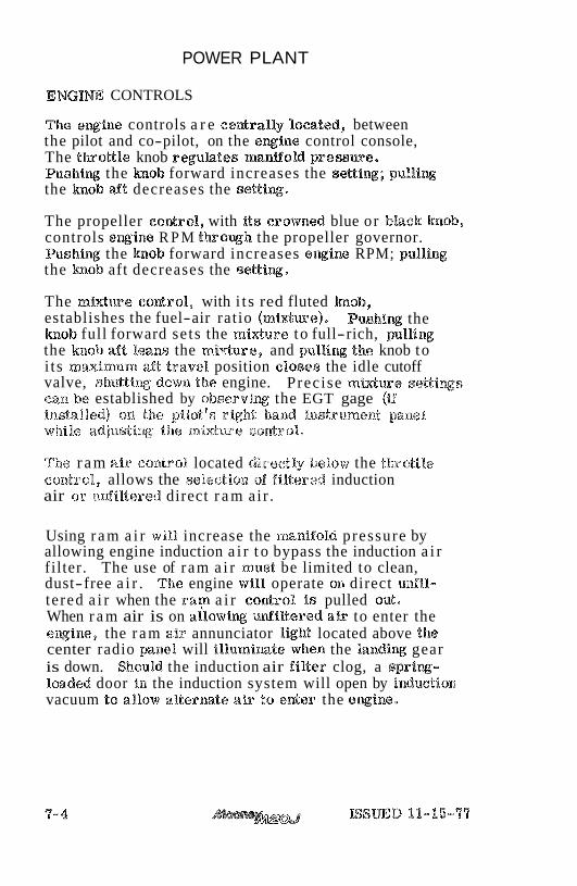
ENGINE CONTROLS
The ewine controls a r e cedra l ly located, between the pilot and co-pilot, on the ewg;ine control console, The t h o t t l e knob reguh tes mangold p resswe . Pushi% the h o b forward increases the se t t iw; p u l l i ~ the h o b aft decreases the settiwg;.
The propeller eodro l , with i t s crowned blue or black h o b , controls @wine R P M t h o q h the propeller governor. Pushi% the h o b forward increases e x i n e RPM; pulUng the h o b aft decreases the setti%*
The mMwp_.e co&ro%, with i t s red fluted Bmob, establishes the fuel-air rat io ( m i d w e ) . Pushi% the h o b full forward se ts the m%ure to full-rich, pull iw the knob d t leans the mivture, and pulling the knob to i t s m a i m u r n aft travel position c losss the idle cutoff valve, shk~ttiaag dowxn the engine. Precise m i d m e settings can be established by o b s e r v i x the EGT gage (if Bnb%alRed) oBn. tias pilot's rigklk laaatd instrument panel while adjusting the mi&ure control,
The r a m air control located directly below the thaott ls control, allows the selection of PiBtered induction air o r u ~ j i l t e r e d direct r a m ai r .
Using r a m a i r will increase the manifold pressure by allowing engine induction a i r t o bypass the induction a i r filter. The use of r am a i r must be limited to clean, dust-free a i r . The engine will operate on direct unfil- te red a i r when the r a y a i r control is pulled out. When r a m air is on allowiw m i l t e r e d air to enter the e x i n e , the r a m air annunciator ligM located above $he center radio panel will illumimte when the h n d i w gear is down. Should the induction air f i l ter clog, a s p r i q - loaded door in the induction system will open by induction vacuum 10 allow al tesmte a i r tta enter the e q i n e .
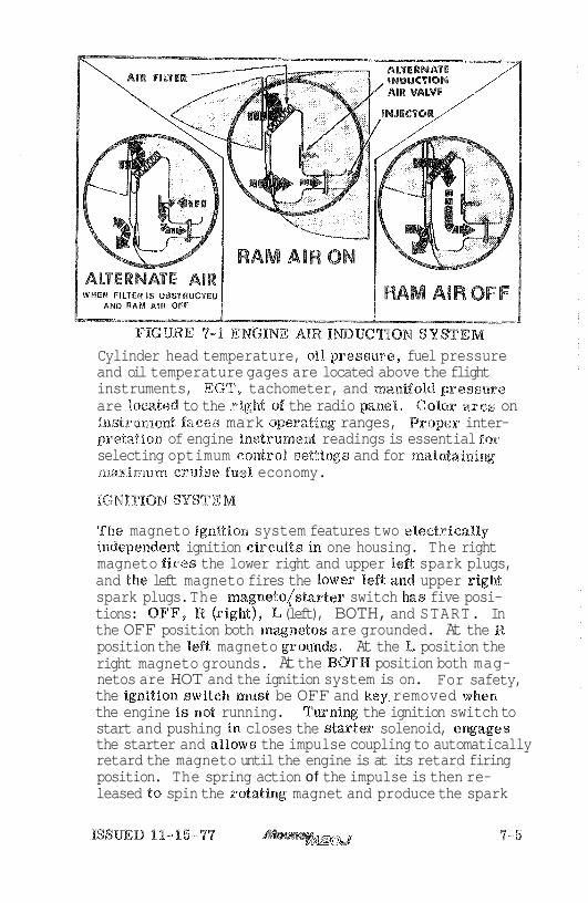
Cylinder head temperature, oil pressme, fuel pressure and oil temperature gages are located above the flight instruments, EGT, tachometer, and mansold presstare are located to the rigM of the radio panel. Golor arcs on instrument faces mark aperatim ranges, Proper inter- pretation of engine instseamen,t readings is essential Boa: selecting optimum control settings and for 113aintainiw mmimiam cruise fuel economy.
IGNE'TIBN SYSTEM
The magneto ignltiora system features two eBectrica%%y independed ignition circuits in one housing. The right magneto fires the lower right and upper left spark plugs, and the left magneto fires the lower %eft anad upper right spark plugs. The magnetolstarter switch has five posi- tions: OFF, $8, (right), L (left), BOTH, and START. In the OFF position both mwnetos are grounded. At the R position the %eft magneto grounds. At the L position the right magneto grounds. At the BOTH position both mag- netos are HOT and the ignition system is on. For safety, the ignition switeia mast be OFF and key. removed when the engine is not running. Tmning the ignition switch to start and pushing in closes the stuter solenoid, ewages the starter and allows the impulse coupling to automatically retard the magneto until the engine is at its retard firing position. The spring action of the impulse is then re- leased to spin the rotating magnet and produce the spark

t o f i re the engine. After the engine s t a r t s , the impulse c o u p l i ~ f%yveigMs do not engage due to centrifugal action. The coupling thenacts as a straight drive and the magneto f i res a t the normal firing position of the engine. The m a g neto/starter switch is spring loaded to return from START to the BOTH position when released.
Do not operate the s tar ter in excess of 30 seconds o r re-engage the s tar ter without allowing it time t o cool.
Do not turn ttae propeller when the ~nagnetos a r e NOT grounded. Ground the magneto points before re rno~r iw switch wires or electrical plugs. ARZ spark plug leads can be removed as a n alternate safety measure
Fuel is carried in two integral sealed sections of the forward inboard a rea of the wings. Total usable fuel capacity is 64 gallons, Both tanks have fuel %eve% indicators visible t h o u g h the filler ports. These indica- t o r s show the 25-gallon level in each tank. There a r e sutnp drains at the lowest point in each tank for taking fuel samples t o check for sediment contamfmtton and condensed water accumulation.
The recessed thee-posit ion fuel selector handle ait of the console on the f1oor allows the pilot to se t the selector valve to LEFT tank, RIGHT tank, or OFF position, The gascohtor , located to the left of the selector valve in the floorboard, i s for draining condensed water and sediment f rom the Iswest point in the fuel lines before the f i rs t flight of the day and after each refueling,
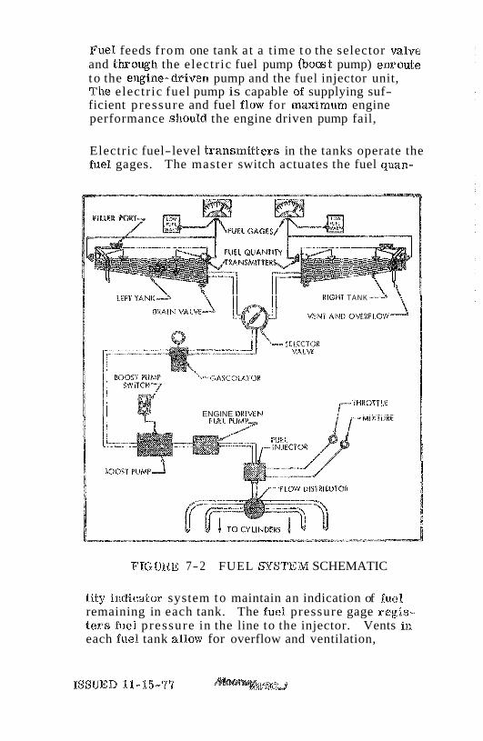
Fuel feeds f rom one tank at a time t o the selector valve and tharowh the electr ic fuel pump (boast pump) emoute to the ewine-driven pump and the fuel injector unit, The electr ic fuel pump is capable of supplying suf- ficient pressure and fuel %%ow for maximum engine performance should the engine driven pump fail,
Electric fuel-level transmitters in the tanks operate the fuel gages. The master switch actuates the fuel quan-
RIGHT TANK
--GASCOLA'IOW
ENGINE DRIMN
FIGURE 7-2 FUEL %STEM SCHEMATIC
t i ty indicator system to maintain an indication of fuel remaining in each tank. The fuel pressure gage regis- t e r s fuel pressure in the line to the injector. Vents in each fuel tank allow for overflow and ventilation,

OIL SYSTEM
The engine has a full-pressure wet-sump oil sy&em wit11 an $-quart .capacity. An automatic bypass control valve routes oil flow around the oil cooler when operating temp- era tures a r e below normal or when the cooling radiator is blocked,
ENGINE COOLING
The down-&aft engine cooling system p r o a d e s ground and inflight power plant cooling. Engine baffliw directs a i r over and around the cylinders and out the cowl flap openiws. Qpeniw the cow% flap doors allows proper a i r flow on the ground and during low- speed high-pow er climbs. Pulling the cow% flap control full a& opens the cow% flaps. The cowl flaps should be partially opened, (control pulled aft approximately two %Q t h e e inches), if necessary t o maintain the oil anad cylinder head temperature within the normal operating range.
VACUUM SYSTEM
An. engine-driven vactrum pump s~applies sucttc~n for t h e vacuum-operated gyroscopic flight fnstrumer~ts, Air entering the vacuum.-pyowd instruments i s filtered; kaence, sluggish or erra t ic operation of wcuu-xn-driven instruments may indicate that a clogged vacuum filter element I s preveaating adequate air intake. A vacuum annunciator light is provided to monitor system operation,
PROPELLER
The propeller, of the constant speed type, is a single- acting unit in which hydraulic, pressure? opposes the natural, centrifugal twisting moment of the rotating blades, and the force of a spring, to obtain the correct pitch for the engine load. Engine lubricating oil is supplied to the power piston in the propeller hub throtagh the propeller shaft, The amount and pressure of the oil supplied is controlled by an engine-driven governor. Increasing engine speed will cause oil to be admitted to the piston, thereby increasing the pitch. Conver sely , decreasing engine speed will result in oil leaving the piston, thus decreasing the pitch.
7-8 ISSUED 11-15-79

FLIGHT PANEL a CONTROLS FAMILIARIZATION
FLIGHT mSTRUMEN%S AND CONTROL$
@ RADIO MASTER The Radio Master Swit~k~/Circuit Breaker operates a relay supplying power to the radiobus bars . Sincethe relay i s energizedto cut the power to the radio bus, f a i lwe of the relay 6301% will still allow power to the radio bus. Energizing the s tar ter automatica%%y ener - gizes the relay and disconnects tfae radios from the bus.
@ MAStPER SWITCH
The master switch operates the battery relay which corkrols battery power to the main ship bus bar. Tlais switch also cuts the alternator field power - from main bus to the alternator. This cuts off a l l ships power except the cabin Eight and electric clock.
@ TURN COORDINATOR (if installed)
The turn coordinator takes the place of a turn and bank indicator and operates from an electric power source. The turn coordinator is independent of the flight reference gyros. The turn eoordir?-~tor displays varia- tions in ro l l and yaw to the pilot by means of a damped
d 0
-4
ig, m a
Q
Q)
k
8,
h
c
car Sa O
W
-w
U
@ k
k
0 0
@ VERTICAL SPEED MDICATOR (if installed)
The vertical speed indicator depicts airplane rate of climb or descent in feet per minute. The pointer is actuated by am atmospheric pressure change supplied by the static source.
@ GEAR SAFETY OVERRIDE SWTCH
The gear safety override switch is a mech- anical means of electrically bypassiw the airspeed safety switch, In the event the gear contra% switch is inadvertently placed in the gear-* position, the gear airspeed safety switch prevents the gear being retracted before approximately '95 MPH a h s p e d i s reached, Should it be necessary to re t rac t at lower airspeed the gear safety override switch may be pressed allowing the gear lo retract .
The activation of the gear safety override switch overrides the safety features of the airspeed switch and can cause the gear to start retraeti~~g wMle sax title grouaad,
@ GEAR SWITCH
"$he electric gear switch identifiable by i ts wheel shaped h o b , is a two-position switch. Pu%%ing aft and lowering the knob lowers the landing gear whi le pulling aft and raising the knob ra ises the gear.
FaiBure to "PUB$" h o b out prior to movement may result in a broken switch.
MAGNETIC COMPASS The magnetic compass i s Hquid-filled, with expansion provisions to compensate for temperature changes. Kt i s equipped witla compensating magnets adjustable from the front of t h e case. Access to the compass light and the compensating magnets i s provided by pivoted
covers, No maix~temnce is required on the compass except an occasional check on a compass rose with adjustment of the compensation, if necessary, and rephcement of the %amp,
@ FWIP SWITCH
The flap switch in a r ecess on the rigM of the console, operates the electrically-actuated wide span wing flaps, Holding the spring-loaded switch in the down position lowers the flaps to the desired angle of deflec- tion. A pointer in the center console indicates flap position, Simply releasing downward pressure on the switch allows i t to return to the OFF position stopping the flaps at any desired intermediate position during extension. When flap-up position i s selected, flaps will re t rac t to full up position unless the switch. is returned to the neutral pos i t i~r l for a desired inter- mediate setting. Pushing the switch to the U P position re t rac ts the flaps;
Wing flap position is mechanically ixadicated $Barer. a cable mobanted directly to the flap jackshaft. A pointer in the flap position indicator indicates flap position. 'Rbe intermediate mark i r a the pointer range i s the flap 'RAKEOFF setting.
The illuminated gear-down position indicator in the back of the fueB selector, t r im pan aft of the center console has two marks that align when the gear i s down and illuminates when the green gear down light i s on,
Rotating the t r i m control wheel forward lowers the nose while rearward rotation ra i ses the nose d the air craft.
@ TRIM POSmION INDICATOR
Rabilizer t r im position is mecknical ly indicated t h u a cable attached to the t r im wheel mechanism. Position indickaelons a r e shotvn on the conso%e.
@ PIToT IIEAT SWITCH/CIRC UIT BREAKER (if installed)
Push iw ON the pitot heat combination rocker switch/ circuit breaker t u r n s on the heating elements within the pitot tube. Should a short occur the combination switch/circuit breaker will automatically t r ip to the OFF position.
P 6 W m G WGHT W I T C H / C ~ C U ' R BREAKER @ Push iw ON tho landing Light combination rocker
switch/circaait breaker turns ONtiae landing BigRat. Skliould a short occur the combimtion switc%a/ circuit breaker will automatically t r ip to the OFF position, The landing light should not be operated when the enginre is not rungling to preclude oves- heating of tkae la mp.
NAVIGATION LIGHT $WITCB/CIRCUE BREAKER hshircag ON the navigation light combimtion rocker switcka/cir@uit breaker turns ONthe wing tip and tail navigation lights. Should a shoat occur the com- bimtton switch/circuit breaker will automatically t r ip to the OFF position,
Q STROBE EIGHT S W I T C H / C I R C ~ T BREAKER (if installed) R s h i n g ON the strobe light combimtion switch/ circuit breaker twnsON the wing t ip strobe lights, Should a short occur the combination switch/cdrcuit breaker w i l l automatical%y t r ip to the OFF position.
@ ROTATING BEACON SWITCH/CIRCUIT BREAKER (if installed)
Pushharag ON the rotating beacon combimtion switch/ circuit breaker turns ON the rotating beacon. Should a short occur the combination switch/circuit brealcer will automatically t r ip to the OFF position.
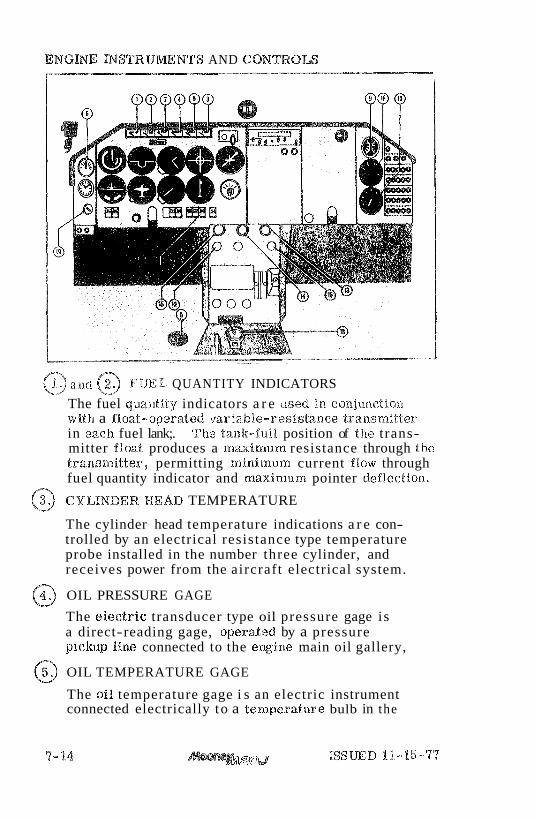
ENGME NSTRUmNTS AND CONTROLS
@ and @ FUEL QUANTITY INDICATORS
The fuel qraantitgr indicators a r e eased in coeajunctio~2 with a float-opera8;ed variable-resistanw traa~smMter in each fuel lank;. Tlae Bank-full position of the trans- mitter float produces a maximtarn resistance through the tra.nsmitter, permitting minlrn~am current flow through fuel quantity indicator and maximum pointer def%ection.
@ CYLINDER HEAD TEMPERATURE
The cylinder head temperature indications a r e con- trolled by an electrical resistance type temperature probe installed in the number three cylinder, and receives power from the aircraft electrical system.
@ OIL PRESSURE GAGE
The electr ic transducer type oil pressure gage is a direct-reading gage, operded by a pressure pic1wp line connected to the engine main oil gallery,
@ OIL TEMPERATURE GAGE
The oil temperature gage i s an electric instrument connected electrically to a temperature bulb in the
e q i n e . Temperature c b w e s of the engine oil c h w e the electrical resistance in the bulb thereby allowing more or less current to flow through the indicating gage.
@ AMMETER
The ammeter indicates current flow, in amperes , from the alternator to the battery, or from the battery to the electrical system. With the engine operating, and master switch "ON", the ammeter indicates the ra te of charge being applied to the battery. In the event of an a l termtor maHunction, or if the electr ical load demand exceeds the a l ter - m t o r output, the ammeter will indicate the d i s c k r g e ra te of the battery,
@ FUEL PRESSURE GAGE The fuel pressease gage i s of the electric transducer type and i s calibrated in potmds per square bnci~, and indicates the pressure to tkae fuel injector,
'$he gascolator, located to the left of the console on the floorboard, allows the pilot to drain condensed water and aray sediment from the lowest point in the fuel line. To activate the gascolator pull the ring upward, to stop drafmge release the ring.
The EGT/OA$ gage i s located to the right of the radio panels and above the engine tachometer, A thermocouple probe in the number 3 exhaust pipe transmits temperature variations to the indicator mounted in the instrument panel. The indicator se rves a s a visual aid lo the pilot when adjusting mixture. Exhaust gas temperature varies with fuel- to-air rat io, power and RPM, The OAT, gage pro- vides the pilot with the f ree s t ream outside a i r temperature in degrees ceaatigrade.
ISSUED 11-15-77 7-15

@ TACHOMETER
The tachometer is a mechanical indicator dr iven a t half c r a d s h f t speed by a flexible shaft. M ~ s t tachometer difficulties will be found in the driveshaft. To function properly, the shaft housing must be f r ee of kinlts, dents and s h a r p bends.
@ MANIFOLD PRESSURE
The manifold p re s su re gage is of the d i rec t reading type and is mounted above the engine tachometer , The gage i s calibrated in taaches of mercu ry and indicates the p r e s s u r e in the induc- tion air manifold.
@ RAM AIR CONTROL
Pralling the ran1 a i r control a%%ows the u se of unfiltered air. The use of r a m a i r must be limited t o clean dust- f r e e a i r and nlust not be used during any ground opera- tions.
i$3 MrXTUHE CONTROL
?'.he mixture: con.trob allows the pilot to adjust the fuel- air r a t i o (mixture) of the engine, Pushing the control forward r ichens the mixture. Pulling the control aft leans the mixture and pcllliaag the control ful l aft c loses the idle cutoff valve shutting down the engine. The control i s of the vern ier type and fine adjustments of the mixture can be obtained by turning the knob, clockwise r ichens the mixture, counter- clockwise leans.
@ PROPGL'LER CONTROL Pushing the propeller control forward increases engine RPM; pulling the control aft dec reases the engine RPM. The control i s of the vern ier type and fine adjustments of R P M q s can be obtained by turning the h o b clocliwise increases R P M q s , counter- clocltwise dec reases RPMqs.
@ THROTTLE CONTROL Pushing the throttle control forward inc reases the manifokd p re s su re thereby increasing the engine power.
7- 16 ISSUED 11-15-77
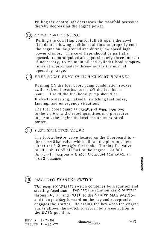
Pulling the control aft dec reases the manifold p r e s s u r e thereby decreasing the engine power.
@ COWL FLAP CONTROL Pulling the cowl flap control full aft opens the cowl flap doors allowing additional airflow to proper ly cool the engine on the ground and during low speed high power c l imbs. The cowl flaps should be partially opened, (control pulled aft approximately th ree inches) if necessa ry , t o maintain oil and cylinder head tern per;^ t u r e s a t approximately three- fourths the normal operating range.
@ F U E L BOOST P U M P SWlTCH/ClRCUlT BREAKER
Pushing ON the fuel boost pump combination rocker switch/circuit breaker tu rns ON the fuel boost 11u1np. Use of the fuel boost pump should be limited to s tar t ing, takeoff, switching fuel tanks , landing, and emergency situations,
The fuel boost pump I s capable of stapplying fuel t o the engine R I the ra ted quantities and p r e s s u r e s l o permit the elagia-le to develop nlarnianu.rn ra ted power.
FUEL SELECTOR VALVE
The fuel se lector valve located on the floorboard is a three-posit ion valve which allows the pilot to se lect either the left or right fuel tank. Turning the valve to OFF shuts off a l l fuel to the engine. At full
The magneto/starter switch combines both ignition and s tar t ing functions. Turning the ignition key c lockvise through W , L, and BOTH t o the STAR'$ MAG position and then pushing forward on the key and recep tac le engages the s t a r t e r . Releasing the key when the engine s t a r t s allows the switch ca r e t u r n by spr ing act ion t o t h e BOTH position.
REV D 3- 7- 84 ISSUED 11,-L5-77

MISCELLANEOUS INSTRUMENTS, CONTROLS AND INDICATORS
@ RADIO LIGBT SWIIT.CEI AND DIMMER
Turning the radio light switch kxiob clockwise t u r n s ON the rad io and indicator lights. Continued turning clockwise inc reases light intensity.
@ RADIO PANELS Adequate space i s provided for installation of optional avionics.
@ PANEL WGBT SWITCH AND DIMMER Turning the panel light switch knob clockwise tu rns ON the ins t rument lights located in the glareshield. Continued turning clockwise inc reases the lighting intensity.
@ CIRCUlT BREAKER PANEL Push- to- reset and push-pull circuit b r e a k e r s auto- matically b reak the e lect r ical current flow if the s y s t e m s rece ive a n overload.
7- 10 ISSUED 11- 15-77
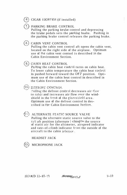
@ CIGAR LIGHTER (if installed)
@ PARKING BRAKE CONTROL Pulling the parking bralce control and depress ing the bralie pedals s e t s the parking bsalte. Pushing in the parlting brake control r e l e a s e s the parking brake.
@ CABIN VENT CONTROL Pulling the cabin vent control aft opens the cabin vent, located on the r ight s ide of the a i rplane. Optimum use of the cabin vent contsol i s descr ibed ii1 the Cabin Environment Section.
9. CABIN HEAT CONTROL 0 Pulling the cabin heat control t u r n s on cabin heat. T o lower cabin t empera tu re the cabin heat control is pushed forward toward the OFF position. Opti- mum use of the cabin heat control is descr ibed in the Cabin Environment Section.
@ DEF.ROSrY CONTROL Pulling the defros t control d e c r e a s e s a i r ffow t o cabin and i n c r e a s e s air flow over the wind- shield in the f ront of the g b r e s h i e l d a r e a . Optimum use of the defros t control is des- cr ibed in ttae Cabin Environment Section,
0 ALTERNATE ST'A'TTC SOURCE VALVE Pulling the a l t e rna te s t a t i c s o u r c e valve to the "ill aft position (alternate ) ck tnges the source of s t a t i c a i r for the a l t i m e t e r , a i r speed indicator and rate-of-climb indicator f rom the outside of the a i r c r a f t t o the cabin in te r io r .
HEADSET JACK
@ MICROPHONE JACK
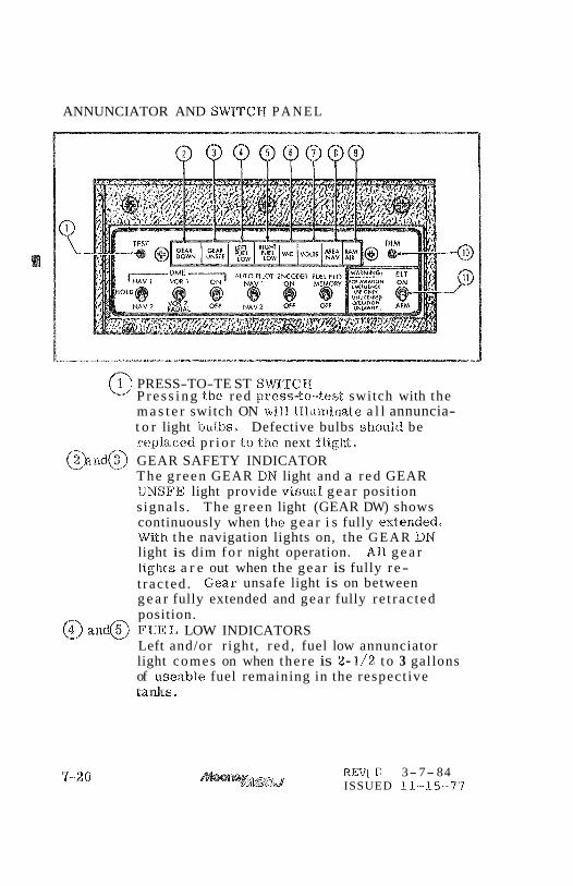
ANNUNCIATOR AND SWITCH P A N E L
9 QQQQQQQ
1 PRESS-TO-TE ST SWL'GGH @ P r e s s i n g tlre r ed press-to-test switch with the m a s t e r switch ON wl1.l illuminate a l l annuncia- t o r light bu.lbs. Defective bulbs should be repXa.ced p r i o r t.o the next flight
@)and@ GEAR SAFETY INDICATOR The g r e e n GEAR DN light and a r e d GEAR UNSFE light provide visual g e a r position s ignals . The g reen light (GEAR DW) shows continuously when the g e a r i s fully extended, With the navigation lights on, the G E A R DN light is dim f o r night operation. All g e a r lights a r e out when the gear is fully r e - t rac ted . Gear unsafe light is on between g e a r fully extended and gear fully re t rac ted position.
@ and@ FUE E LOW INDICATORS Left and/or right, r e d , fuel low annunciator light comes on when the re is 2-1/2 t o 3 gallons of useable fuel remaining in the respect ive tanks.
REV1 D 3- 7- 84 ISSUED 11-15-77
V A C U U M hlA EF UNCTION lNDlCATOR The r e d V A C annunciator light indicates a n~nlfunctiota o r improper acljustmcnt of a i r suction sys tem. Air sanction i s available for operation of the attitude gyro, and also the directionat% gy ro , and w i l l be shown in inches of mercury. The des igmted snction range
, . j i s 4,2510 5 .5 inctaes of mercury. The vac light will $%ink when suction is below 4.25inclies oh mercury and g ives a steady light when suction is above 5 . 5 Inches of mercury , 111 e i ther ca se the gyros should not be conasidered re i iab le during t h i s warning time.
@ VOLTAGE RREGIJWlRLTY INDICATOR The red. VOLTS annunciator iiglat comes on desig- nating improper voltage supply. A red blinlting light designates %ow, or no voltage f rom the miternstor: a steady r e d light indicates aver voltage o r a trippage of the va%bge relay*
'@I AREA NAV FUNCTION INDICATOR The blue A R E A NAV Wight refers only t o the ON ar OFF position of speciific navigation ecgrafpnaent,
61 R A M All3 POSITION INDICATOR The amber RAM AIR ,anrr%agaciator Bight is a rea~lin- der thaw& r a m air system i s in% operation wtae~~ tlte ge,lr comes d s w ~ and should be turned off to reroute air t i s r o ~ h a i r f i l ter .
@ DIM SWITCH The DIM switch may be adivatedi when the %ow fuel lights come an briglat, '6he switcla w i l l dirn both low fuel lights bui wi l l no% tu rn them off. To re- store the display to bright, p r e s s tlae test sirritch,
EMERGENCY LOCATOf? TRANSXqITTEW SWITCH The E L T switch mmnally xctivales the eme~xency %ocntor tsansnlitler located ina the tallcone. To activate the sys tem pull the s ~ ~ i t c l a out and r a i s e , Failure Lo pu%% out can resul t in a brealb?ge of tlae switch. Iaeferelace s l~ould be made to f lie E ~ ~ ~ e r g e n c y Locator T ransmi t t e r sect io~a for proper and latvful usage of the EL$.
REV A
FLIGHT CONTROLS
PRIMARY FLIGHT CONTROLS
4 Push-pull tubes with self-aligning rod end bearings actuate the pr imary flight control surfaces. A spring- loaded interconnect device indirectly joins the a i le ron and rudder control sy s t ems t o a s s i s t in la te ra l stability during flight maneuvers. Control surface gap s e a l s minimize airflow t h o u g h the hinge s lo ts and reduce drag.
TRIM CONTROLS
For pitch t r i m control, the ent ire empennage pivots on the ta i l cone attachment points t o increase or dec rease the horizontal s tabi l izer angle, This design allows flight t r i m establishment with minimum control surface de- flection. A t r im indicator on the console indicates s tabi l izer t r i m position, In flight, forward rotation of the t r i m wheel Rowers the nose; rearward rotation r a i s e s the nose.
WING FIAP CONTROLS
The flap control i s located in a r e c e s s on the right s ide of the elagilae control console and operates the electr ic- ally-actuated wide-span wing f laps, Moving the control. to the U P position, r e t r a c t s the f laps, The position of the f laps can be noted f r o m the flap position indicator located adjacent to the t r i m indicator. Holding the control in the down position moves the flaps down until the desired position is reached, releasing the control s tops flap movemefit. Limit switches prevent flap t rave l above o r below t r ave l limits.
PlTOT STATIC SYSTEM
A pttot tube, mounted on the lower surface of the %eft wing, picks up a i r speed indicator r a m a i r . A heated pitot prevents pitot tube icing when flying in moisture- laden a i r . A pitot sy s t em dra in valve i s located on the forward bottom skin of the left wing just outboard of the wing fillet. Static posts on each side of the tai l cone
supply stat ic air pres for the al t imeter, the air- s p e d hd ica to r , a& the ee&ical speed Indicator. A static -&ern &ain valve is l o a t 4 on the f u s s Q e bdtorrrm sMn below the tail cone access d m r . An al$er- m t e s ta t ic p r e s s m e s o m c e mlve is fln&a%led under the lei% fligM pane% above the p i l d e s left. h e e .
STALL WARNflNO SYSTEM
The electr ical stal l warniw system uses a mne-actmted switch, installed in the leB w i w Beadiq e k e , t o energize a stal% warning horn located in the cabin. The stal l warn- ing switch is adjusted t o p rodde aura% wwning at 5 to 10 MPH before the a c t w l stall is reached and will remain on until the a i rcraf t flight attitude b cbwged.
EMERGENCY LOGATOR TRANSMlTTER The Emergency Locator Transmitter (ELT) is located in the forward partion of the tailcone and is aeceasfbla by removiw the radio access panel on the left s ide of Lhs fuse%age. The emergency loeator transmitter meets the requirements of FAR 91-52 and is adsmatically aeti- vated by a lol-agftudinal force of 5 to '7 g's. The ELT t ransmits a dis t ress signal on both 62%. 5 MHz as~d 243. O MHz for a period of from 448 horns In low temperature a r e a s and up to 109 how8 in high temperature a reas . The unit operates on a self-contained battery.
The battery has a useful life of four years . However, to comply with FAA regulations it m& be r e p b c e d aRer two years of shelf life. The battery sk~ould a lso be re- placed if the transmitter has been used in a n emergency situation or if accumulated test t ime exceeds one hour. The rep lacemed date is marked on the transmitter label.
On the unit itseU is a three position selector switch l~lacarded "OFF", "ARM
, qvONqq. The "ARMqq position is prodded t o set the unit t o the aeP$omatic position s o that it will t ransmit only after impact and will continue to transmit until the battery is drained to depletion or until the switch is manually moved to the "OFF" goasition* The "ARM" position is selected when the t ransmiger I s in- stalled a t the factory and the switch should remain in that
position whenever the unit is indal led in the a i r p h ~ e . The "ONqv
position is proaTHded s o the unit a n be used a s a portable transmi#er o r in the event the automatic fea- ture was not triggered by impact or to psr id ica l ly test the function of the transmitter .
Select the "OFFsq position when c k n u n g the battery, when rearming the unit 'if it haas been actimted for any reason, o r t o discontinue transmission.
If the switch has been placed in the "ON position for any reason, the "OFF" position has to be selected before selecting "ARM". If "ARMvq is selected directly from the "ONf' position the unit will continue to transmit in the "ARM" position.
A pilot's remote switch, located above the radio panel, is p r o ~ d e d to allow the transmitter to be controlled from inside the cabin. Tiae pi%otvs remote switch is placarded "ONqP9 "ARMSqr
The locator should be checked durix~g the ground check Co make certain the unit 1aa.s n d been accidentally actiwted. Check by tuning a radio receiver to 3121.5 MHz. U there is an oscillating sound, the locator may have been acti- vated and should be turned off immediately. Reset $0 the "ARMqv
position and check again t o insure against outside interference.
If for any reason a test transmission I s necessary, the operator must f i rs t obtain permission from a local FAA/Fcc representative (or other applicable Authority) or in a c c o r a n c e with current regu- lations. Test transmission should be kept to a minimal dmation.
ISSUED 11-15-77
LANDsNC GEAR
ELECTRIC GEAR RETRACTIOH 8
The two-position electric gear control switch, identified by i t s wheel-sbped h o b , i s located near the top of the instrument p a m l above the t b o ~ l e . There a r e two ways t o check that the electrically-actated gear is down:
(1) The green gear-down annunciator light is ow, (3) The indicator m a r k align a s seen on. tile floor-
board v i sml gear-position indicator, A green GEAR DN Bight, a red WSAFE light? and a w a r n i ~ horn provide v i s m l and audible gear position s igmls . The green Bight (GEAR DN) shows continuously when the gear is fully e&eded . With the mvigation ligMs on, the GEAR DN Hght is dim for night operation. All gear lights are off when the gear is fully retracted,
Retarding the throttle below 12 inehee manifold pressure causes the gear warrrxiw horn l o emit an i ~ ~ t e r m l t t e d tone i f the gear is nd dov~n.
To prevent faadvertent rebaction of &he bhnding gear system an airspeed actuated sdety switch is fmtalled In the pitot system. The switch is n d I d e ~ d e d to sub- stitute for the gear switch in Beepix the gear extended while t a x i i ~ , t 8 M ~ - o B , or h n d i ~ ,
Never re ly on the safety switch t o keep the gear down d u r i w taxi, take-off or b n d i x . Always make certain that the l m d i x gear switch is in the down position d w i q these operations,
The aircraft is also q u i p p d with a bn.diw gem mfety bypass sw.itch override should the gear fail t o re t ract after take-off. Gction EI discusses the procedure to be used s$lould the B m d i ~ gear safety switch fail t o de-activate after take-off,
ISSUED 11-15-77
E m R G E N C Y GEAR-EXTENSION SYSTEM
The emergency gear edension pull cord located between and aft of the sea t s is for manmlly d r i v i q the electric gear actmtor to extend the gear if the electric system maBunctions, Section $11 discusses the emergency gear extension ~p%.oeedure.
BRAKE & STEERING SYSTEm
The main gear wheels incorporate seH-adjusting disc- typo hydraulic brakes. The pilot's rudder pedals have individual toe-actmted brake cylinders linked to the rudder pedals. D e p r e s s i q the toe pedals and pulling out the p a r k i q brake control on the console se ts the brakes. Pushing the parking brake control forward rele&ses the b rakes .
%$ i s not advisable to set the parking brake when the brakes a r e overheated, after heavy braking or when outside Cemperatwes a r e unusually high. Trapped hydraulic fluid may expand with heat and damage tlas system. Wheel chocks and tiedowns should be used for lo~g-tersam parking.
Rudder pedal action s t ee r s the noae wheel, Gear se- traction rel ieves the rudder coea$rol system of i t s nose wheel steering and centers the wheel to permit retraction into the noae wheel well. The minimuan tu rn fw radius saa. the ground is 41 feet.
ELECTRICAL POWER
ALTERNATOR & BATTERY
A l%volt 35-ampere-hour storage battery in the tailcone and a 60-ampere self-rectlying alternator supply electrical power for eqtaipment operation. The ammeter inthe engine instrument display indieatesbattery charg&ischarge rate. A power loss in the alternator or voltage regulator will be shown a s adischarge reading on the ammeter; a disciaarged battery will be indicated a s a high-charge reading.
The voltage regulator ad juds alternator output t~ currant load while maintafniw a constant voltage level. A voltage warning light ilhumimtes steadily when voltage limits a r e exceeded and $%ashes when the voltage is low.
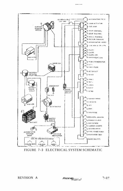
- -
FIGURE 7- 3 ELECTRICAL SYSTEM SCHEMATIC
REVISION A
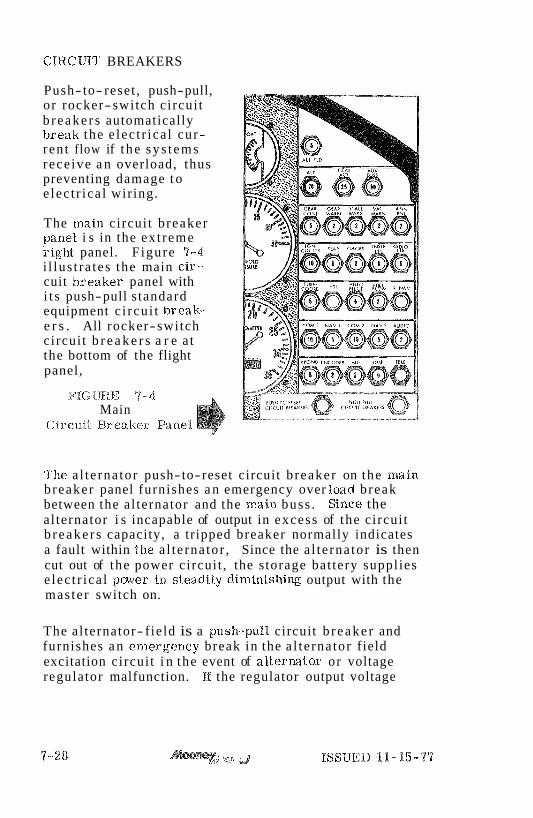
CIRCUIT BREAKERS
Push- to- reset , push-pull, or rocker- switch circui t b r eake r s automatically brealc the e lec t r ica l cur- ren t flow if t he sy s t ems rece ive a n overload, thus preventing damage t o e lec t r ica l wir ing.
The main circui t b reaker parael i s in the ex t reme sight panel. F igure 7-4 i l lus t ra tes the main cis- cuit b reaker panel with i t s push-pull s tandard equipment c i rcu i t break;- e r s . All rocker- switch circui t b r e a k e r s a r e a t the bottom of the flight panel,
Main Circuit Breaker fiPanel
The a l te rna tor push- to-reset circuit b reaker on the main breaker panel furnishes a n emergency over load break between the al ternator and the main buss . Since the al ternator i s incapable of output in excess of the circui t b r eake r s capacity, a tripped breaker normally indicates a fault within the a l te rna tor , Since the a l te rna tor is then cut out of the power circui t , the s torage bat tery suppl ies e lec t r ica l paver in steadily di.rninishing output with the mas te r switch on.
The al ternator- f ield is a push-pull circuit b r eake r and furnishes a n emergerlcy break in the a l te rna tor field excitation circui t i n the event of a l ternator or voltage regulator malfunction. If the regulator output voltage
71, )J ISSUED 11-15-77

exceeds l imits , the r e d voltage warning light illuminates steadily. Turning off the rad io mas ter switch and then turning mas t e r switch off and on, will r e s e t the voltage regulator . The overvoltage annunciator Eight should r ema in out. E the overvoltage light comes on again, pulling out the alternator- field circui t breaker cuts the al ternator out of the power circui t . Once again the battery is the only source of electr ical power; there- fore , a l l e lectr ical equipment not essent ial for flight shoulld be t u n e d off and the flight terminated as soon as pract ical to cor rec t the rnalfmction.
ANNUNCIATOR LIGHTS
The landing gear lights, low fuel light, volt- age lights, and r a m a i r lights a r e grouped in the annunciator and switch panel. A tes t switch, dim switch, and ELT switch are also found in the panel and each of tlae lights and switches a r e discussed elsewiaere i n t h i s section,
A l l ia~strurnelnt faces and placards are IloodligEated by Hght bulbs In the glareshield. There a r e two rheostat k~aobs on the right hand radio panel, the left control regulates the intensity of the instrumerats and placard lighting. The right contr 01 provides avionic lighting. Rotating the knobs clockwise t u n s on and increases light intensity.
A dome light iillraminates the cabin. Its BRICHT- OFF-DIM switch is silight1.y forward. and t o the right of the dome light.
EXTERIOR LIGHTING
Coaaventional navigation and higia intensity s t robe lights a r e installed on the wing tips. A landing and taxi light is installed on the right s ide of the lower engine cowling. All exterior lights a r e controlled by rocker type switciaes on the lower left portion of the instrument pane l o
ISSUED 11-15-97
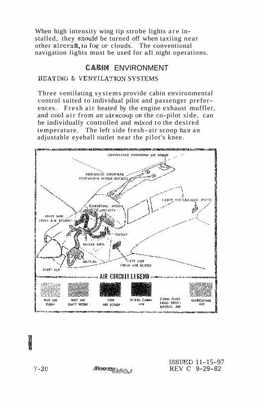
When high intensity wing tip strobe lights a r e in- stalled, they should be turned off when taxiing near other aircraf t , in fog or clouds. The conventional navigation lights must be used for a l l night operations.
CABIN ENVIRONMENT PIEATING & VENTIUTION SYSTEMS
Three ventilating sys t ems provide cabin environmental control suited t o individual pilot and passenger prefer- ences. F r e s h a i r heated by the engine exhaust muffler, and coo% a i r f rom an airscoop on the co-pilot s ide, can be individually controlled and mixed t o the des i red temperature. The left side fresh- air scoop Baas an adjustable eyeball outlet near the pilot 's knee.
AIR ClRCUlT LEGEND - - - v
MOT AIR SIDE MIXED CABIH cABIN OVER QlFROSTlMG DUCT WOllU AIR SCOOP MEAD VTPdT-
A'' IIATIMG AIR AIR
ISSWD 11-15-97 REV C 9-29-82

The cabin overhead ventilating sys t em works independently of the cabin heating and ventilating sys tem. F resh a i r en t e r s an intake on the dorsa l fin and is controlled by individual eyeball outlets above each sea t*
The cabin heat control is marked CABIN HEAT, Pulling the cabin heat control aft supplies heat t o the cabin and defroster system. The cabin vent control is marked VENT. Pulling the vent control aft supplies f r e sh a i r to the lower cabin and the defrost syptern. Mot and cold a i r may be mixed by adjusting both heat and vent controls. These controls may be adjusted between full open and full closed. The right side airscoop laas outlets under the s ide panel for installation of radio cooling ducts,
WNDSHIE LD DEFROSTING SYSTEM
The windshield defrost system takes a i r f rom the cabin a i r distribution sys tem and distr ibutes this a i r over the windsk~ield interior surface any t ime tlae heal and/or f r e s h air valves a r e opened, Pulling the defrost control full aft decreases %&ow to the cabin and fo rces maxim.um air to f low through the defrost ducts.
SEATS & SAFETY BELTS
The frant s ea t s a r e individually mounted and may be adjusted fore and aft t o fit individual comfort prefer- ences. Resetting a sea t back i s accomplished by pulling the sea t back forward, rotating the large cam selector knob a t the lower back juncture, and allowing the back to r e tu rn to the new position.
REVISION A

SAFETY HARNESS
The single diagonal type harness i s designed s o the chest s t r ap c r o s s e s diagonally f rom the outboard shoulder t o an attachment point as low on the inboard hip as passible. C a r e should be taken t o conform with t h i s location in ad- justing the chest s t r a p and inboard belt length. This diagonal configuration places the body center-of-gravity inside the t r iangle formed by the chest s t r a p and b p belt. The lap belt should be adjusted comfortably tight. As a resul t the body is res t r ic ted f rom rolling out toward the unrestr icted shoulder , o r "open" s ide of the harness , upon forward Impact.
BAGGAGE& CARGOAREAS
The baggage compartment has . I7 cubic feet of baggage or cargo space and two pairs of floor liedown s t r a p s , The Roase equipment, cons is t s of wing jackqoints and tiedown r ings , a fuel sampling cup, and a towbar, These a r e stowed in the baggage compartment. The r e a r seat back may be removed for additional, cargo space by removing attaching bolls a t lop and bottom of s ea t back.
lf des i red for any r ea son the baggage door can, be opened f rom the inside even tlaough locked.
To re-engage outside latch; open outside hatch fully, c lose inside latch and push in on white button until latched, Operate outside latch in nor ma1 method,
REVISION A
SECTION V I I I . HANDLING. SEMVlClNG & MAIHTENMCE
TABLE OF CONTENTS
TITLE PAGE
INTRODUCTION . . . . . . . . . . . . . . . . . 8-2
G R O m D mNDLKNG . . . . . . . . . . . . . . . 8-3 . . . . . . . . . . . . . . . . . . . . TOWING 8-3
TIEDOWN . . . . . . . . . . . . . . . . . . . . 8-4 JACmNG . . . . . . . . . . . . . . . . . . . . 8-4
. . . . . . . . . . . . . . . . . . . . SERVICING 8.5 REFUEUNG . . . . . . . . . . . . . . . . . . 8-5 ENGINE LUBRICATION . . . . . . . . . . . . 8-6 INDUCTION AIR FILTER* . . . . . . . . . 8-8 GEAR ANDrrBRE . . . . . . . . . . . . . . . . 8-9 BATTERY . . . . . . . . . . . . . . . . 8-9 KiiYDRABS:LJC BRAKE RESERVOIR . . 0 8-10
This section contains factory recommended procedures for proper ground handling, routine c a r e and s e r ~ c i n g of your Mooney,
As required by Federal Aviation Regulations, a l l civil aircraft of U. S. registry must undergo a complete in- spection (ANNUAL) each twelve calendar months. In addition t o the required ANNUAL inspection, aircraft operated commercially (for hire) must have a complete inspection every 100 hours of operation. A l l inspections must be performed by a desigmted representative of the F A A .
The FAA may require d h e r inspections by the issuance of airworthiness dkectives applicable to the airplane, engine, prope%%er and other components. It is the responsibility of the owner/operator to ensure compli- ance with al l applicable airworthia.~ess di.rectives and, when the fnepedions B r e repetitive, to take appropriate steps to prevent inadvertent noncompliance.
Sc!aeduling of ALL maintenance is the responsibility of tlae aircraft sperator, A genera8 lmow$edge of the aircrafe i s necessary to perform day-to-day service procedures and to determilae when unusual servlce or shop xnaipa&enans.e is naeeded.
SerGce information in this section of tile mane%% is limited to service procedures which the operator will normally perform or s u p e r ~ s e . Reference should be nnade to FAR Par t 43 for information regarding preventive mainternnee which may be performed by a licensed pilot.
It is wise to follow a planned schedule of lubrication and preventive maintemnce based on c%imatic and flying con- ditions encountered in y our locality.
Keep in touch with y o u Mooney Service Center and take advantage of h i s howledge and experience. He b o w s you- airplane and how t o maintain it.
ISSUED 11-15-77

Should an extraordinary or difficult problem a r i s e con- cerning the repair or upkeep of your Mooney, consult the Customer Service Department, Mooney AircraR Corporation, P. 0. Box '52, Kerrdl le , T X '18028, Phone Area Code 512- 896-6000. El
A11 correspondence regarding your airplane should include the model and ser ia l numbers, These numbers can be found on an identification plate located on the lower aft portion of the left side of the tailcone. The model and ser ia l numbers must also be used when consulting either the Service & Maintenance Manual or Par ts W/lanleall.
Service & Maintenance and Par t s Manuals may be obtained for y a w airplane f rom your Mooney Marketing and Service Center.
GROUND HANDLING
For maneesverir~g the aircraft in @Rose quarters, in the !xa"ngar, or ow the r amp , use the tow bas furnished witla the aircraft loose equipment* The lowbar attaches to the nose gear crossbar . One man eaxx move the air- craft prodding the ground surface i s relatively smooth and the t i r e s a r e properly idlated.
When no towbar Is availab%.e, or when assistance in moving the aircraft is required, push by hand: (I) on the wing leading edges, (2) on the wing tips, and (3) on the inboard portion of propeller blades adjacent to &he propeller hub. Towing by tractor or other powered equipment is not recommended,
Exercise care not to t u n the nose wheel past its normal swivel angle of 14O either side of center. Exceeding the turn limits shown on the turn indicator may cause structural damage.

As a precaution against wind damage, always t i e down the aircraft. when parked outside. Removable wing ttiedown eye-bolts, supplied with the loose equipment, sc rew into wing receptac les marked HOIST POINT just outboard of each main gea r . Replace these eyebolts with jack point f ixtures when it i s necessary t o lift the a i r c r a f t with jacks. The t a i l tiedown point is park of the t a i l skid.
To t i e down the a i rc ra f t : a . P a r k the airplane facing the wind. b. Fas ten the co-pilot seat belt througla the
flight control wheel. c . Fas ten s t rong ground-anchored chain or rope
t o tlae installed wing tiedown eyebolts, and place wheel chocks fore and aft of each wheel.
d , Fasten a s t rong ground-anchored chain or rope through the ta l l skl.d,
When it i s necessary to r a i s e the a i rc ra f t off the ground: a . Install jack polalts in tiedown ma~aaatirag holes
outboard of each main gear . b. 8Jse s tandard a i rc ra f t jacks a t both wing hoist
paints (wing tiedown eyebolt receptacles) outboan-d of the main gears . While holding jack point in place, r a i s e jack t o f i rmly con- tact jack point.
c . Ra ise a i r c r a f t , keeping wings a s nearly level a s possible.
d. Secure safety Xoclcs on each jack. e . Use a yoke- frame jack under propel ler t o
lift the nose.
Do not r a i s e tlae a i rc ra f t on jacks out of doors when wind velocity i s over 10 MBM (8 KTS), When low- e r ing a i r c r a f t on jacks, bleed off p ressuze on a l l jacks simultane- ously and evenly t o keep a i r c r a f t level a s i t i s lowered,
32 jJ ISSUED 11-15-77
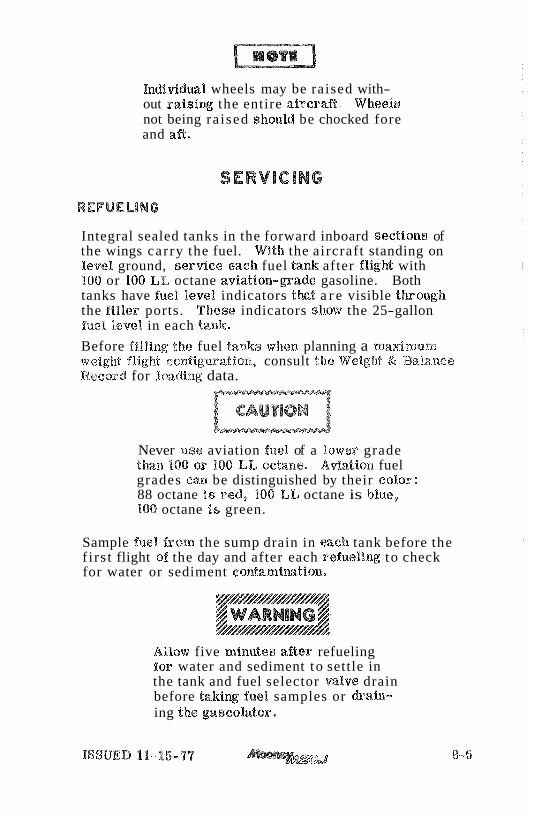
IndividuaP wheels may be raised with- out r a i s i q the entire aircrafi. Wheels not being ra ised should be chocked fore and aft.
Integral sealed tanks in the forward inboard sections of the wings carry the fuel. With the aircraft standing on %eve$ ground, s e r d c e each fuel tank after fligM with 100 or 1100 L k octane aviat ion-pade gasoline. Both tanks have fuel level indicators t k t a r e visible t h o u g h the filler ports. These indicators sk~ow the 25-gallon fue l %eve% in each t a n k
Before filling the fuel tanks when planning a maximum weig%at flight ccodiguratian, consult t h e WelgM & Balance Record for l a d i n g data.
Never use aviation fuel of a lower grade than 100 or 180 L%iJ octane. Adation fuel grades can be distinguished by their color: 88 octane is red, 188 LL octane is blue, 108 octane I s green.
Sample fuel from the sump drain in each tank before the f i rs t flight of the day and after each refueling to check for water or sediment contamimtion,
Allow five minutes a&er refueling for water and sediment to settle in the tank and fuel selector valve drain before t a k i q fuel samples or drain- ing the gascoh to r ,

Tank sump &ains a r e near each wing root forward of the wheel wells. A smal l plastic cup is supplied in the loose qu ipment kit for obtaining fuel samples. To @o%lect a fuel sample, inser t the cup actuator prong in the sump drain receptacle and push upwwd to opera the valve mo- mentarily and drain fuel into the cup. I% water is in the fuel, a distinct line separating the water f rom between the gasoline will be seen through the transparent cup wall. Water, being laeavier, will settle to the bottom of the cup, while the colored fuel will remain on top. Continue taking fuel samples until a%% water is purged from the tank. The fuel tank gascolator control is on the cabin floor forward of the pilot's seat, To flush the gascolator sump and the lines leading from the wing tanks to the selector valve, turn the selector handle t o the left, and pull the fuel drain control for about five seconds. Repeat the procedure for the right tank, being s u r e that the fuel drain col~trol ring is returned to the closed position and that the drain salve is not l e a k i q -
The new L,yeoming engiale has been carefully run-in and tested a t t he factory. Operate tias new engine at full power within the limitations given in Section 11. Before every fliglat, check the engine oil level and replenish a s neeeeexy ,
Check engine oil level after engine has been stopped long enough for oil to drain back into sump. The oil filler cap access door is located in the top cowling. Any lubricating oil, either straight mineral or compounded, must conform with Lycoming Specification No. 301E to be acceptable for use in Lycoming ewines . New or newly over-hu%ed engines should be operated on aviation grade straight mineral oil during the f i rs t 25 taours of operation or until oil consump- tion has stabilized. The aircraft is delivered from Mooney with straight mineral oil of the correct viscosity,
The engine is equipped with an external oil filter and the engine oil c b w e in termls may Qe extended to $00-hour i d e r v a l s proAding the e A e r m l filter element is chawed A T 50-HOm INTERVALS. If an engine Lms been opera t iw on straight mineral o i l for several hura&ed

hours, a change to additive oil should be undertaken with caution, If the e g i n e is in an extremely dirty condition, the switch to additive oil should be deferred until after engine has been overhauled. When c b n g i ~ from straight mineral oil t o additive or compounded oil, after several hm&ed hours of operation on straigM mineral oil, take the following precautiomry steps:
a . Do not mix additive oil and strafght mineral oil. m a i n straigM mineral oil from engine, c b n g e filter and fill with additive oil.
Po. Do not operate engine longer than five hours before again changing oil,
c. Check oil filter for evidence of sludge or plugging. Chaw@ oil and replace oil filter element every 10 hours if sludge is e~dexxtae. Resume normal oil drain periods after sludge c~ndi t ions improve.
Y a w M~hsoney Service Center will ckaaxe the engine oil fa%. addition t o performing all other service and inspection procedures needed when you bring youa airplane in for i t s 50- hour, 100- hour, or a % n ~ ~ u l inspections. Excessive of $
sludge buildup indicates that the oil system needs servicing at less tha.sn 50- hour i~~terprals
When c h a q i n g or adding oil Eyeornix specifies tkae fo%%owing grades of oil t o use for m.rious ambient a i r temperatures.
Average *Recommended Grade Oil Ambient A i r Single Viscosity Multi Viscosity
above 6O0F 30° to 9 0 ' ~
OQ to vI0F Below l 0 ' ~
SAE 50 40 or 50 8AE 40 40 SAE 30 40 or 2BW-30 SAE 20 20W-30
"Refer t o the latest edition of Lycorning Service Instruc- tion Na , 11014,
ISSUED 11-15-77

Your Mooney Service Center bas apvoved brands of l u b r i c a t i ~ oil and a l l consumable materials necessary to service your airplane.
lNDUGTlON AIR FILTER SERVICBNQ
The importance of keeping the induction a i r filter clean cannot be over-emphasized, A clean filter promotes fuel economy and longer engine life. The dry-type Donaldson filter can usually be washed six t o eight t imes before rephcement is necessary. Replace the induction, a i r filter every 500 hours or a t one-year intervals, whichever occurs f irst .
1. To clean the Domldsow dry-type induction a i r filter: a . Remove the top engine cowling. b. Remove filter element. c, Direct a jet of a i r against down or clean side of
filter (opposite t o normal airflow). Keep a i r nozzle a t least two inches from filter element. Cover entire filter a rea with a i r jet.
Do not use a compressor w i t wi th a nozzle pressure greater than ROO PSI,
d. After cleaning, inspect filter and gasket for damage. Discard a ruptured filter or broken gasket.
If filter shows an a c c u m u k t i ~ n of carbon, soot, or oil, continue with cleaning steps e,through h.
e. Soak filter in nonsudsing detergent for l5 minutes; then agitate filter back and forth for two to five minutes to free filter element of deposits.
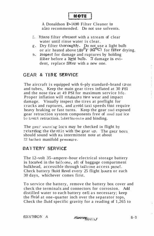
A Donaldson D-1400 Filter Cleaner i s a lso recommended. Do not use solvents.
f . Rinse filter element with a s t ream of clear water until r inse water i s clear.
g. Dry filter thoroughb. Do not use a light bulb or a i r heated above 1 8 0 ~ ~ ($2 '~ ) for f i l ter drying.
!a. Inspect for damage and ruptures by holding filter before a light bulb. E damage is evi- dent, replace filter with a new one.
GEAR S T l R E SERVICE
The aircraft i s equipped with 6-ply standard-brand t i r e s and tubes, Keep the main gear t i r e s inflated at 30 PSI and the nose t i re at 49 PSI for maximum service life. Proper inflation will minimize t i r e wear and impact damage. Visually inspect the t i r e s at preflight for cracks and ruptures, and avoid taxi speeds tkaat require heavy braking or fast turns. Keep the gear and exposed gear retraction system components free of rrrud 2nd ice to overt retraction. interferenee and binding.
The gear warning horn may be checked in flight by retarding the t k o t t l e with the gear up. The gear horn should sound with an intermittent note a t about 92 inches manifold pressure.
The 12-volt 35-ampere-hour electrical storage battery is located in the tailcone, aft of baggage compartment bulkhead, accessible through tailcone access paneb. Check battery fluid Revel every 25 flight hours or each 30 days, whichever comes first.
To service the battery, remove the battery box cover and check the terminals and connectors for corrosion. Add distilled water to each battery cell a s necessary; keep the fluid a t one-quarter inch over the separator tops, Check the fluid specific gravity for a reading of 1,265 to

1.275. A recharge is necessary when the specific gravity is 1.240 or lower. %art charging at four amperes and finish at two amperes; do not allow battery tempera- ture to r i s e above 120°F during recharging. Keep the battery at full charge to prevent freezing in cold weather and to prolong service life.
The alternator and voltage regulator operate only a s a one-polarity system. Be stare the polarity i s correct when connecting a charger or booster battery.
If corrosion i s present, flush the battery box with a solution of baking soda and water. Do not allow so& to enter the battery cells, Keep cable connections clean and tightly fastened, and keep overflow lines free of obstruction.
HYDRAULIC BRAKE RESERVOIR SERVICE
The brake system hydraulic reservoir i s located in the tailcone above the battery. To service, remove tkae tali- cone a.ccess panel and check fliaid level every 50 hours of operation. Fluid level should be no higher t lun two (2) inches below the filler cap. Use only hydraulic fluid (Red) eonfor ming to specification MIL- H.-5608. DO NOT FI LI, reservoir while parking brake is set .
MAINTENANCE
PROPELLER CARE
The high s t r esses to which propeller blades a r e subjected makes their careful inspection and maintenance vitally important. Check the blades for nicks, cracks, or indi- cations of other damage before each flight. Nicks tend to cause high-stress concem$rations in the blades which, if ignored, may result in cracks. It is very important that a l l nicks and scratches be polished out prior to next flight.
It is not unusual for the propeller blades to have some end play or fore and aft movement a s a result of manufactrsing
tolerances in the parts . This has no adverse affect on propeller performance or operation and is no cause for con- cern i f the total movement at the blade tip does not exceed . 12 inches. With the f irst turn, cedrifugal force firmly seats the blades, rigidly and positively again& the re tedion bearing in the propeller hub.
Preflight inspedion of the propeller blades shmld include in addition to the foregoing an occas%om% wiping with an oily cloth to clean off g rass and bug stains. Never use an a l k l i n e cleaner on the blades; remove grease and di r t with tetrachloride or Soddard solvent. McGlauley recommends the propeller be removed and over k u l e d every 1200 hours of operation,
Your Mooney Service Center will answer any questions you may have concerning blade repair and inspection.
EXTERIOR CARE
As with any paint applied to a metal searface, an initial curing period is necessary for developing the desin-ed qualities of durability and appearance, Therefore, da not apply wax or polish t o tlae new a i reraR e d e r i o r until! two or t&aree months after delivery. Wax substances will seal paint from the a i r a~ad prevent curing. Do wash the exterior t o prevent dir t from w o r k i ~ ~ g into the cwing but hold buffing to a minimum until cwing is complete and there is am danger of diaturbie~g the mdercoat*
Before washing the exterior, be certain the brake discs a r e covered, a pitot cover is in pbce , and a l l static-air bt&ons a r e maslced off. Remove grease or oil from the exterior by wiping with a cotton cloth saturated in kerosene. Flush away loose dir t and mud deposits before washilag the e d e r i o r with an aircraft-type washing compound mixed in warm water, Use soft cleaning cloths or a c k m o i s , and avoid harsh or abrasive detergents t h t might scrateia or corrcde the smface . It is essen th l that a l l cleaning com- pounds and application cloths be free of abrasives, gri t , or other foreign matter. Use a prewax cleaner to remove a heavy oxidation film. For nonoxidized or precleaned surfaces, apply a good exterior finish wax rwommenaded for protection of urethane enamel finishes. Carefully follow the manufacturer's instructionsa A heavier coating of wax

on the leading edge of the wings, empenmge, and nom section will laelp reduce drag and abrasion in these w e a s ,
B fuel, hydraulic fluid, or any other dye-containing sub- stance is found on the exterior paint, wash the a rea at once t o prevent staining. Pmmediately flush away spilled battery acid, and t rea t the a rea with a baking so&-and-water solu- tion, followed by a washing with a mild aircraft detergent and warm water.
Before wiping the wiladows or windshield, flush the exterior with clear water to remove particles of dirt. Household window cleaning compounds should not be used a s some contain abrasives or solvents which could harm plexiglas. An anti-static plexiglas cleaner i s good for cleaning and polishing the windshield and windows.
INTERIOR C A R E
Normal household cleaning practices a r e recommended for routine interior care . Frequently vacuum clean the seats , rugs , upholstery panels, and iaeadliner to remove a s muc82 surface dust a.nd dirt as possible. Oecasiona%ly wash tias teather cxr vinyl uphols"cery and kick panels with a mild soap solution "% prevent dirt from worKng into the surface. Wipe clean with. a slightly damp cloth and dry with a soft ccTatka. Never apply furniture polishes. Foam-type shampoos and cleaners for vinyl, leather, texkiles, and plastic materials a r e g o d for removing stains and reconditioning the entire interior. Spray dry cleaners a r e a lso recommended. Grease spots on fabric should be removed with a jelly-type spot lifter
Never use denatured a%coho%, benzene, carbon tetrachloride, acetone, or gasoline for cleaning plexiglas or interior plastics. Caref~~eally folXow the manufacturerfs instructions when using commercial c % e a n i x and finishirg compounds.
Do not saturate fabrics with a solvent which could damage the backing and padd ix materials, To minimize carpet wetting, keep foam a s dry a s possible and gently rub in circles. Use a vacuum cleaner t o remove foam and to dry the materials. Use a damp cloth or a mild soap solution to cleaaa interior garnish plastic, vinyl t r im, and metal surfaces.
ISSUED II-15-TT

Certain miscellamous data, information and licenses a r e a par t sf the a b p h n e file. The followiw is a checklist sf documents that must either be carried in the airplane or available on request of the proper autlaority.
1. To be displayed in the a b p h n e a t al l times:
(a) Aircraft Airworthiness Certificate (FAA Form 8100-2) (b) Airera& Registration Cer t f iea te (FAA Form 8050-3) (c) Aircraft Radio Ration License, 16 t ransmiger
installed (FCC Form 556).
2. To be carr ied in the airplane during a l l flight operations:
(a) Pilot's Operating Handbook (including FAA Approved
(b) Weigl~t and Balance, and associated papers (latest copy of the Repair anad Alteration Form, FAA Form 337 , i f applicable).
(e) Equipment List.
The or ig iml weigM and b a l a ~ ~ c e data and Equipment Idst are contained in Section VP of this manml, when the ~maanaml is supplied with a new airplane pwcbased from Mooriaey Aircraft Corporation. It is recommended that copies of Section &Pbe m d e and stored in a safe place .
3. To be made available upon request:
(a) Airplane Log Book (b) Engine Log Book
Since the Regulations of other nations may r q u i r e other documents and data, owners of airplanes not registered in the United R a t e s should check with their own aviation officials t o determine their i~adivfdual requirements,