Embed Size (px)
Citation preview
This article was downloaded by: [Universidad de Chile]On: 08 September 2014, At: 11:16Publisher: Taylor & FrancisInforma Ltd Registered in England and Wales Registered Number: 1072954 Registered office: Mortimer House,37-41 Mortimer Street, London W1T 3JH, UK
Structure and Infrastructure Engineering:Maintenance, Management, Life-Cycle Design andPerformancePublication details, including instructions for authors and subscription information:http://www.tandfonline.com/loi/nsie20
Steel corrosion and service life of reinforced concretestructuresLuca Bertolini aa Politecnico di Milano, Dipartimento di Chimica , Materiali e Ingegneria Chimica ‘G. Natta’, via Mancinelli, 7-20131, Milano, ItalyPublished online: 25 Jun 2008.
To cite this article: Luca Bertolini (2008) Steel corrosion and service life of reinforced concrete structures, Structureand Infrastructure Engineering: Maintenance, Management, Life-Cycle Design and Performance, 4:2, 123-137, DOI:10.1080/15732470601155490
To link to this article: http://dx.doi.org/10.1080/15732470601155490
PLEASE SCROLL DOWN FOR ARTICLE
Taylor & Francis makes every effort to ensure the accuracy of all the information (the “Content”) containedin the publications on our platform. However, Taylor & Francis, our agents, and our licensors make norepresentations or warranties whatsoever as to the accuracy, completeness, or suitability for any purpose of theContent. Any opinions and views expressed in this publication are the opinions and views of the authors, andare not the views of or endorsed by Taylor & Francis. The accuracy of the Content should not be relied upon andshould be independently verified with primary sources of information. Taylor and Francis shall not be liable forany losses, actions, claims, proceedings, demands, costs, expenses, damages, and other liabilities whatsoeveror howsoever caused arising directly or indirectly in connection with, in relation to or arising out of the use ofthe Content.
This article may be used for research, teaching, and private study purposes. Any substantial or systematicreproduction, redistribution, reselling, loan, sub-licensing, systematic supply, or distribution in anyform to anyone is expressly forbidden. Terms & Conditions of access and use can be found at http://www.tandfonline.com/page/terms-and-conditions
Steel corrosion and service life of reinforcedconcrete structures
LUCA BERTOLINI*
Politecnico di Milano, Dipartimento di Chimica, Materiali e Ingegneria Chimica ‘G. Natta’,
via Mancinelli, 7-20131 Milano, Italy
(Received 26 January 2005; accepted in revised form 6 June 2005)
This paper illustrates the mechanisms of corrosion of steel in concrete, and analyses its
influence on the service life of reinforced concrete structures. Even though other types of
corrosion are mentioned, attention is focused on the effects of carbonation and chloride
penetration. Factors affecting the time to corrosion initiation are described with regards
to both concrete properties and environmental exposure conditions. Propagation of
corrosion and its consequences on the serviceability and performance of the structures are
illustrated. Approaches for the design of durable reinforced concrete structures, as well as
options available to increase the service life of structures exposed to aggressive
environments, are described.
Keywords: Carbonation; Chloride; Corrosion initiation; Corrosion propagation;
Reinforced concrete; Service life
1. Introduction
From the beginning of the twentieth century, the combined
use of concrete and steel reinforcement became common
practice and led to a widespread use of reinforced and
prestressed concrete in the construction of structures and
infrastructures throughout the world. As concrete in itself,
from the time of Romans, had shown a good performance
even under unfavourable environmental conditions, it was
initially assumed that reinforced concrete could also be
considered as an intrinsically durable construction materi-
al. Nevertheless, especially from the second half of the
twentieth century, degradation of reinforced concrete (RC)
structures became a major problem and structural engi-
neers, as well as material scientists, had to focus on it. It
appeared that very often durability of reinforced concrete
structures was limited by the corrosion of the steel
reinforcement (Page and Treadaway 1982, Tuutti 1982,
Arup 1983, Scheissl 1988, Page 1998, Bertolini et al. 2004).
Towards the end of the twentieth century, a series of reasons
led to an increased awareness of the effects of corrosion of
the steel reinforcement. First of all, developments in cement
and concrete technologies were mainly aimed at improving
the mechanical performances of concrete, while durability
issues played a marginal role. If this allowed the use of more
strength-performing materials, especially at early ages, it
eventually contributed to permit a generalized decrease in
the quality levels at the construction sites (Neville 2001).
Furthermore, the increase in the use of reinforced and
prestressed concrete, for a wide range of structures and
infrastructures even under aggressive environments (such as
marine or de-icing salts exposure conditions) and their
consequent degradation brought about a huge increase in
rehabilitation costs. This raised the awareness of owners of
the structures and designers of the necessity to prevent
corrosion of steel and, in general, degradation of reinforced
concrete.
Nowadays, durability has become a critical issue in the
management of RC structures. Furthermore, designers of
RC structures are now aware that, even though quality
controls at the construction site are essential for obtaining a
durable structure, prevention of steel corrosion has to be
taken into consideration from the design stage. Therefore,
there is a need for tools aimed at the design of durable
*Corresponding author. Email: [email protected]
Structure and Infrastructure Engineering, Vol. 4, No. 2, April 2008, 123 – 137
Structure and Infrastructure EngineeringISSN 1573-2479 print/ISSN 1744-8980 online ª 2008 Taylor & Francis
http://www.tandf.co.uk/journalsDOI: 10.1080/15732470601155490
Dow
nloa
ded
by [
Uni
vers
idad
de
Chi
le]
at 1
1:16
08
Sept
embe
r 20
14
structures. However, these can only emerge from a clear
understanding of the mechanisms leading to the corrosion
of steel and the factors involved in corrosion initiation and
propagation. Although a lot of work has been carried out
in the last two decades, especially by working groups of
several organizations (e.g. CEB (1992), Rilem (1995),
Frederiksen (1996), CEB (1997), COST 509 (1997), ACI-
365 (2000), Duracrete (2000), Rilem (2000), COST 521
(2003)), there are not yet generally accepted procedures for
the design of concrete structures with regards to corrosion
prevention.
This paper summarizes the main aspects of corrosion of
steel in reinforced concrete and describes possible ap-
proaches for the design of durable structures. A more
detailed description of aspects related to corrosion preven-
tion can be found in Bertolini et al. (2004).
2. Corrosion mechanisms
Steel in sound concrete is protected by the alkaline solution
contained in the pores of the hydrated cement paste, which
promotes passivation, i.e. the formation of a spontaneous
thin protective oxide film on the surface of the steel (Gouda
1970, Arup 1983). Under this condition, the corrosion rate
is negligible, even if the concrete is permeated by oxygen
and moisture. However, corrosion can take place when the
passive film is removed or is locally damaged. This may
take place due to carbonation of concrete or to chloride
penetration. Carbonation is the neutralization of the
alkalinity of concrete due to carbon dioxide in the atmo-
sphere; it brings about a drop in the pH of concrete from its
normal values of pH 13 – 13.8 to values approaching
neutrality, which are too low for the stability of the passive
film. Therefore, when carbonation reaches the steel surface,
the steel bars are no longer passive and they can corrode,
provided oxygen and moisture are available. If the pore
solution contains enough high concentration of chloride
ions, the passive layer may be locally destroyed, even in
alkaline concrete. When chloride ions, which are contained
for instance in seawater or in common de-icing salts,
penetrate the concrete cover and reach a critical level at the
depth of the reinforcement, a localized attack can take
place (which is named pitting corrosion). Again, moisture
and oxygen are required at the steel surface for the
propagation of this attack.
Corrosion may have several consequences on the
serviceability and safety of reinforced concrete structures.
Oxides produced at the steel surface can produce tensile
stresses in the concrete cover, which may lead to cracking,
spalling in localized areas, or delamination. Reduction of
the bond of the reinforcement to the concrete may also
occur. In the case of localized corrosion, the cross-section
of the reinforcement can be significantly reduced and thus
the load-bearing capacity of a structural element, its
ductility and seismic behaviour, as well as its fatigue
strength, may be affected even before any cracking takes
place in the concrete cover.
The effects of carbonation and chlorides on the
performances of RC structures will be analysed later on.
Nevertheless, it is useful to remember that, under specific
circumstances, two other forms of corrosion could take
place.
Possible effects of stray current need to be considered in
structures of railway networks, such as bridges and tunnels,
or structures placed in the neighbourhood of railways. In
the presence of electrical fields in the concrete, stray
currents can enter the reinforcement in some areas and
return to the concrete in a remote site (Pedeferri and
Bertolini 2000). In the case of stray DC current, the passive
layer can be destroyed in those areas where an anodic
reaction takes place, i.e. where the current leaves the steel.
Fortunately, laboratory studies have shown that, in
contrast to its effect on metallic structures in the soil, stray
DC current rarely has corrosive consequences on steel in
concrete. In fact, passive steel in alkaline and chloride-free
concrete has a high intrinsic resistance to stray current.
Nevertheless, under particular circumstances, corrosion can
be induced on the passive reinforcement, especially if
chlorides contaminate the concrete even at levels that are,
in themselves, too low to initiate pitting corrosion
(Bertolini et al. 2001).
High strength steels used in prestressed concrete are
rather vulnerable to the effects of corrosion. Because of the
high stress normally applied to prestressing tendons or
bars, even a modest corrosion attack may promote failure
(Nurnberger 2002). If high strength steel is not adequately
protected due to poor detailing or poor workmanship and
inadequate grouting, it can be exposed to aggressive species
(e.g. water and chlorides) especially in the most vulnerable
parts of the structures, such as anchorages or joints, and
consequent corrosion can have serious consequences on the
structural performance. Furthermore, under very specific
environmental, mechanical loading, metallurgical and
electrochemical conditions, hydrogen embrittlement (HE)
can occur; this may promote the initiation and propagation
of sharp cracks and lead to brittle fracture of the steel.
Several types of tests have been developed to study the
susceptibility of high strength steels to HE (FIP 1980,
Isecke 2003). It is now believed that HE has a significant
likelihood of occurrence only on steels strengthened by
quenching and tempering, whose production has now been
abandoned. In any case, because of the serious conse-
quences that failure of high strength steel due to either
corrosion or HE may have, special care has to be dedicated
to the protection of pre-stressing or post-tensioning bars. A
document now under discussion in a working group of the
FIB, for instance, concentrates on the protection provided
by encapsulation of post-tensioning tendons inside ducts
124 L. Bertolini
Dow
nloa
ded
by [
Uni
vers
idad
de
Chi
le]
at 1
1:16
08
Sept
embe
r 20
14
(FIB 2004). Corrosion of high strength steel will not be
further considered in this paper.
3. Carbonation-induced corrosion
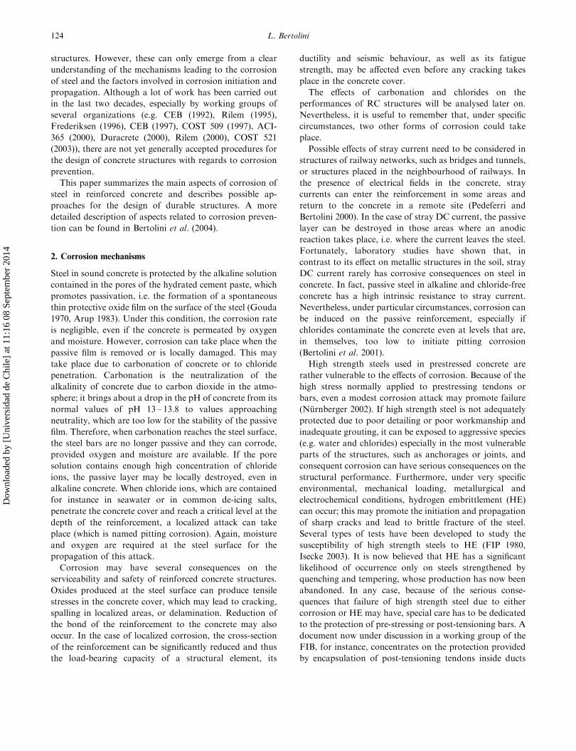
Figure 1 depicts the effects of carbonation on the life of a
reinforced concrete structural element. In a first stage, the
steel reinforcement is passive and no corrosion takes place.
However, carbonation penetrates the concrete cover,
beginning from the concrete surface. Corrosion then
initiates when the carbonation front reaches the steel
reinforcement, even though it does not in itself affect the
serviceability or the stability of the structure. Corrosion
initiation is a critical time in the life of the structure. In fact,
the depassivated steel becomes susceptible to corrosion
with a rate that depends on environmental factors. In time,
corrosion products will cause cracking, spalling and
delamination of the concrete cover, which may compromise
the serviceability and the stability of the structure. Recently
it has been proposed to consider these phenomena, as well
as corrosion initiation, as time-dependent limit states in the
structural design (CEB 1997, Duracrete 2000).
As far as corrosion of steel is concerned, a service life can
be defined as the sum of the initiation time and the
propagation time (Tuutti 1982). The initiation period can
be defined as the time required for the carbonation depth
to equal the concrete cover thickness. The propagation
period begins when the steel is depassivated, and finishes
when a given limit state is reached, beyond which con-
sequences of corrosion cannot be further tolerated. This
distinction between initiation and penetration periods is
useful in the design of RC elements, since different
processes and variables should be considered in modelling
the two phases.
3.1 Corrosion initiation
The initiation stage is governed by the rate of penetration
of carbonation and the thickness of the concrete cover.
The carbonation reaction starts at the external surface, and
its rate of penetration decreases in time as it advances to
greater depths. The depth of carbonation (d) can be rea-
sonably described by a square root of the time (t)
relationship:
d ¼ Kffiffitp: ð1Þ
The evolution of carbonation in time is then simply
described by the carbonation coefficient K (expressed in
mm year70.5).
K depends on environmental factors and on concrete
properties. The moisture content of concrete has a major
role. The carbonation rate is negligible in water-saturated
concrete as the diffusion of carbon dioxide is hindered in
the water-filled pores. The carbonation rate is also
negligible in dry concrete, as the reaction of carbon dioxide
with the alkalinity of the concrete is prevented due to lack
of water. The value of K is higher for intermediate moisture
contents (Tuutti 1982, Parrott 1992, Alonso and Andrade
1994). The highest penetration rate of carbonation is
normally found on sheltered concrete exposed to 60% to
70% relative humidity (e.g. inside a building). The
carbonation rate is lower if the structure is subjected to
periodic wetting. In this case, K depends on the wetting
time as well as the frequency and duration of the wetting-
drying cycles. Since wetting of concrete is faster than
drying, more frequent, shorter periods of wetting are more
effective in reducing the penetration of carbonation than
less frequent and longer periods of wetting (Wierig 1984).
Therefore, the microclimate plays an essential role on real
structures, and carbonation of concrete can be very
variable, even in different parts of a single structure if
these are subjected to different wetting conditions.
The permeability of concrete has a remarkable influence
on the carbonation rate. A lower capillary porosity of the
hydrated cement paste, achieved by decreasing the water/
cement ratio (w/c) and providing adequate curing, slows
down the diffusion of carbon dioxide. The cement type may
also influence the carbonation rate; for blended cement,
hydration of pozzolanic materials or ground granulated
blast furnace slag (GGBS) leads to a lower Ca(OH)2 con-
tent in the hardened cement paste, which may increase the
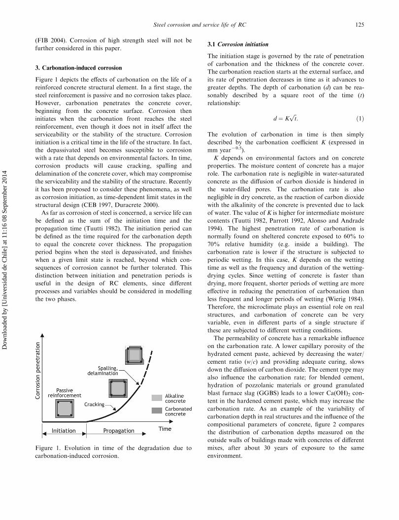
carbonation rate. As an example of the variability of
carbonation depth in real structures and the influence of the
compositional parameters of concrete, figure 2 compares
the distribution of carbonation depths measured on the
outside walls of buildings made with concretes of different
mixes, after about 30 years of exposure to the same
environment.
Figure 1. Evolution in time of the degradation due to
carbonation-induced corrosion.
Steel corrosion and service life of RC 125
Dow
nloa
ded
by [
Uni
vers
idad
de
Chi
le]
at 1
1:16
08
Sept
embe
r 20
14
The carbonation rate is also influenced by the carbon
dioxide concentration in the atmosphere (e.g. it is higher in
close and polluted environments, such as inside tunnels)
and temperature.
3.2 Corrosion propagation
Once the carbonation front has reached the reinforcement,
and thus the steel is depassivated, the availability of oxygen
and water at the steel surface are the controlling factors for
the corrosion rate (Alonso and Andrade 1994). Oxygen
depletion may only occur under complete and permanent
saturation of concrete with water. In other exposure
conditions, the corrosion rate of steel in carbonated
concrete is governed by the electrical resistivity of concrete.
The corrosion rate of steel in carbonated concrete decreases
as the electrical resistivity increases (Alonso et al. 1988,
Glass et al. 1991). A universal correlation between the
corrosion rate of steel and the electrical resistivity of
concrete cannot be found, as this may change according to
the concrete composition and the chloride contamination
(Bertolini and Polder 1997).
The moisture content is the main factor in determining
the resistivity of carbonated concrete. In dry concrete, the
resistivity is rather high and the corrosion rate of steel may
be negligible. Conversely, as the humidity increases,
resistivity decreases and consequently the corrosion rate
increases. Therefore, the evolution of corrosion in time is
strongly dependent on local changes in the moisture of
concrete at the depth of the reinforcing steel. The corrosion
rate, for a given humidity, may be enhanced by the presence
of a small amount of chloride ions in the pore solution, that
come from, for example, the mixing materials or are
penetrated from the environment (Glass et al. 1991). In
order to estimate the growth in time of the oxide layer, then
the actual variations in the moisture content should be
considered. In models for the prediction of the propagation
time, mean annual values of the corrosion rate are usually
considered.
For predicting the propagation time, the maximum
acceptable corrosion penetration needs to be known as
well as the corrosion rate. Very broadly, a penetration of
the attack (assumed to be uniform) of the order of 50 to
100 mm could be considered sufficient to initiate a crack in
the concrete cover. It was, however, shown that cracking of
the concrete cover does not only depend on the penetration
of the corrosion attack, but also on the ratio between the
concrete cover and the diameter of the bars and the
strength of the concrete (Morinaga 1988, Alonso et al.
1994). Further propagation of corrosion may lead to a
progressive increase in the crack width until the concrete
cover spalls (usually beginning at the corners) or delami-
nates (Duracrete 2000).
4. Chloride-induced corrosion
The presence of chloride ions in the pore solution of
concrete may induce a form of localized corrosion on the
embedded steel (which is named pitting corrosion). In
alkaline (i.e. non-carbonated) concrete, this takes place
when the concentration of chloride ions in the pore solution
in the vicinity of the steel surface reaches a threshold value
that is high enough to break down the passive film.
Nowadays, design codes impose strict limits to the amount
of chlorides that can be introduced into concrete during
construction (by means of cement, mixing water, aggre-
gates or admixtures). The risk of chloride-induced corro-
sion is then associated with the penetration of chlorides
through the concrete cover.
The initiation period depends on the rate of penetration
of the chlorides, the chloride threshold value and the
thickness of the concrete cover. Basically, it could be said
that pitting corrosion initiates when the penetration of
chlorides is such that the threshold value is reached at the
steel surface, i.e. at a depth equal to the cover thickness. In
practice, however, evaluation of the initiation time is quite
a complicated task, because of a large number of variables
that influence both the kinetics of chloride penetration and
the chloride threshold value.
4.1 Chloride penetration
Chloride penetration from the environment produces a
profile in the concrete characterized by a high chloride
content near the external surface, and by a decreasing
content at greater depths. The actual profile that can be
obtained in time in a specific point of a given RC element
depends on many factors. The main ones are related to the
Figure 2. Frequency distribution of the carbonation depths
measured on vertical walls built with concretes of different
mixes, after 30 years of exposure.
126 L. Bertolini
Dow
nloa
ded
by [
Uni
vers
idad
de
Chi
le]
at 1
1:16
08
Sept
embe
r 20
14
concrete properties, the mechanisms of transport of the
chloride-bearing solutions, the moisture content of con-
crete, and the concentration of chlorides in the environ-
ment. The transport of chlorides through the concrete
cover may take place due to diffusion, capillary suction,
permeation, and migration mechanisms (CEB 1992,
Frederiksen 1996, Bertolini et al. 2004), depending on local
exposure conditions.
Diffusion occurs due to the presence of a concentration
gradient; when the surface of water-saturated concrete
comes into contact with a chloride containing solution,
chlorides enter through the water-filled pores of the
hydrated cement paste. Under non-stationary conditions
and unidirectional flux, Fick’s second law describes this
phenomenon:
@C
@t¼ D
@2C
@x2; ð2Þ
where C is the chloride concentration at time t and depth x,
and D is the diffusion coefficient. The diffusion coefficient D
is the parameter that characterizes the rate of chloride
diffusion. Penetration by diffusion may occur, for instance,
in elements of a marine structure permanently immersed in
seawater.
Capillary suction is the ingress of a liquid into empty or
partially saturated pores of a hydrophilic material due to
under-pressure in the pores. When the surface of non-
saturated concrete comes into contact with a chloride-
bearing solution, the solution (as well as chloride ions
dissolved in it) is quickly absorbed into the concrete.
Although complex theoretical relationships (taking into
account the surface tension, viscosity, and density of the
liquid, the angle of contact between the liquid and the pore
walls and the radius of the pores) should be used to describe
capillary absorption, a practical parameter called sorptivity
is normally used for comparison purposes. This is measured
by placing the bottom surface of a previously dried sample
in contact with water at atmospheric pressure. As a first
approximation, the mass of liquid absorbed per unit of
surface (i) can be assumed to be proportional to the square
root of time:
i ¼ Sffiffitp; ð3Þ
where the sorptivity (S) is the parameter that characterizes
the rate of capillary suction.
Permeation is the penetration of a liquid due to a
pressure difference. When water penetrates saturated
concrete by pressure, the flow through the pores is defined
by Darcy’s law, which can be written as:
dq
dt¼ kHA
L; ð4Þ
where dq/dt is the flow (in m3s71), H (in m) represents the
height of the column of water-pressure differential across
the sample, k is the permeability coefficient (in m s71), A is
the surface of the cross-section (in m2) and L is the
thickness (in m).
Finally, in the presence of electrical fields, chlorides may be
transported by migration, i.e. the transport of charged ions
present in the pore solution due to the electric field. Even
though in this paper it is not possible to properly describe the
factors affecting migration of ions through concrete, it is
worth remembering that the electrical resistivity of concrete
(r) is a parameter strictly related to ion migration.
In principle, modelling of penetration of chloride ions in
time in a RC element can be carried out by selecting the
relevant mechanism of chloride penetration, by finding an
appropriate value of the parameter describing the rate of
penetration (D, S, k, etc.) and then calculating the
evolution of chloride concentration in time throughout
the structural element. Unfortunately, even if the equations
describing the basic transport phenomena are relatively
simple, this task is much more complicated.
Essentially, all transport parameters depend on the
concrete microstructure. For instance, a decrease in the
porosity of the concrete brought about by a reduction in
the water/cement ratio would decrease the coefficients D, S
and k, while it would increase r. However, the influence of
time has to be considered, since hydration can take place
over long periods, especially in the case of blended cements
with pozzolanic or blast furnace slag additions. Coefficients
determined on the basis of short-term tests on early age
concrete, therefore, may not be representative of the long-
term performance of the concrete. Due to their dependence
on the porous structure of concrete, some correlations can
be found between different transport coefficients, as well as
between these and the concrete strength. Attempts have
been made to correlate the 28-day strength of concrete with
the chloride diffusion coefficient D, or the permeability
coefficient k. However, these correlations, are not of a
general nature, but vary in relation to the composition or
the other properties of concrete. For instance, changing
from portland cement to blended cements, could lead to a
reduction in the chloride diffusion coefficient of more than
one order of magnitude (because of the refinement of the
capillary pores in the cement paste), without any significant
improvement in the strength. Penetration of chlorides in
concrete is also affected by binding, i.e. chloride ions are
adsorbed, or chemically react with constituents of the
cement paste. This alters the concentration of chloride ions
in the pore solution, modifying the kinetics of penetration
and thus the transport coefficients. Binding properties of
concrete can change according to its composition, in
particular with the tricalcium-aluminate content of the
cement or the addition of silica fume, fly ash or blast
furnace slag.
Steel corrosion and service life of RC 127
Dow
nloa
ded
by [
Uni
vers
idad
de
Chi
le]
at 1
1:16
08
Sept
embe
r 20
14
In real structures, the transport of chlorides through
concrete often takes place by a combination of transport
mechanisms (CEB 1992). For example, when a structural
element is exposed to wetting-drying cycles, it is subjected
to capillary absorption of the chloride-bearing solution
during wetting (possibly followed by diffusion during the
wet period), while during dry periods evaporation of water
brings about accumulation of chlorides near the surface.
Conversely, exposure to precipitations may wash out
chlorides in the surface of the concrete. Chloride penetra-
tion in a reinforced concrete structure is thus a complex
function of geometry, position, environment and concrete
composition.
The complex nature of the transport of chlorides in
concrete and the difficulty in evaluating appropriate values
of the relevant transport parameters has led to the adoption
of simplified procedures. The experience of both marine
structures and road structures exposed to de-icing salts, has
shown that, in general, chloride profiles can be reasonably
described by means of the following relationship:
Cðx; tÞ ¼ Cs 1� erfx
2ffiffiffiffiffiffiDtp
� �� �; ð5Þ
where C(x,t) is the chloride concentration at depth x and
time t. This is a solution of Fick’s second law (equation (2))
under the assumptions that concrete does not initially
contain chlorides, that the concentration of the diffusing
chloride ions, measured on the surface of the concrete, is
constant in time and is equal to Cs, that the coefficient of
diffusion D is constant in time and does not vary through
the thickness of the concrete. This relationship was firstly
proposed by Collepardi et al. (1972) to fit profiles of
penetration of chlorides in concrete under diffusion
conditions. As a matter of fact, chloride ions can penetrate
by pure diffusion only in concrete completely and
permanently saturated with water. As previously described,
in most situations other transport mechanisms (e.g.
capillary suction) contribute to chloride penetration, while
binding with constituents of the cement paste may alter the
concentration of free chlorides in the pore solution. In spite
of this, several studies have shown that, even under
exposure conditions where chloride transport occurs by
other phenomena than diffusion, experimentally measured
profiles can be fitted by the ‘erf-function’ in equation (5),
provided suitable values are calculated for Cs and D
(Frederiksen 1996). When other transport mechanisms take
place instead of, or concomitantly to, diffusion, Fick’s law
is not applicable. In these cases, equation (5) cannot be
used to estimate the evolution of chloride profiles in the
future. In order to clarify that equation (5) is used as a
simple mathematical tool for the analysis of chloride
profiles, the value of D interpolated from experimental
data is normally called the apparent diffusion coefficient
(Dapp). In fact, it was shown that the fitting values of Cs and
Dapp change in time (while they are assumed to be constants
in the integration of Fick’s second law). Cs may depend on
the composition of concrete, the position of the structure,
the orientation of its surface and the microenvironment, the
chloride concentration in the environment and the general
conditions of exposure with regard to rain and wind. In
marine structures, the highest values of Cs are normally
found in the splash zone, where evaporation of water leads
to an increase in the chloride content at the concrete
surface. A dependence of Cs on the cement content was also
observed by Bamforth and Chapman-Andrews (1994). Dapp
depends on the pore structure of the concrete and on all the
factors that determine it, such as the w/c ratio, the
compaction, the curing, and the presence of microcracks.
The type of cement has also a considerable effect; in passing
from concrete made with portland cement to concrete made
with the increasing addition of pozzolana or blast furnace
slag, Dapp can be drastically reduced (Collepardi et al. 1972,
Frederiksen 1996). Of particular interest is the addition
of elevated percentages of blast furnace slag to portland
cement, which may reduce the diffusion coefficient by
more than one order of magnitude (Polder and Larbi 1995).
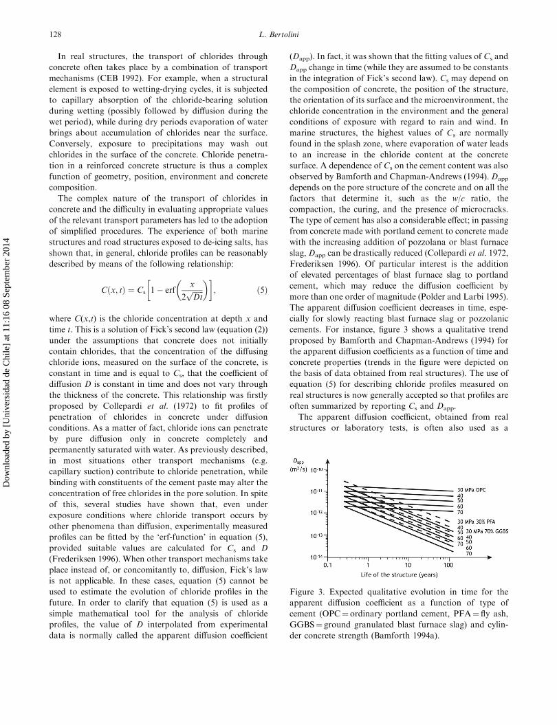
The apparent diffusion coefficient decreases in time, espe-
cially for slowly reacting blast furnace slag or pozzolanic
cements. For instance, figure 3 shows a qualitative trend
proposed by Bamforth and Chapman-Andrews (1994) for
the apparent diffusion coefficients as a function of time and
concrete properties (trends in the figure were depicted on
the basis of data obtained from real structures). The use of
equation (5) for describing chloride profiles measured on
real structures is now generally accepted so that profiles are
often summarized by reporting Cs and Dapp.
The apparent diffusion coefficient, obtained from real
structures or laboratory tests, is often also used as a
Figure 3. Expected qualitative evolution in time for the
apparent diffusion coefficient as a function of type of
cement (OPC¼ordinary portland cement, PFA¼ fly ash,
GGBS¼ ground granulated blast furnace slag) and cylin-
der concrete strength (Bamforth 1994a).
128 L. Bertolini
Dow
nloa
ded
by [
Uni
vers
idad
de
Chi
le]
at 1
1:16
08
Sept
embe
r 20
14
parameter to compare the resistance to chloride penetration
of different concretes, assuming that the lower Dapp is, the
higher the resistance to chloride penetration is. However, it
should be observed that, while the diffusion coefficient
obtained from pure diffusion tests can be considered as a
property of the concrete, the apparent diffusion coefficient
obtained from real structures also depends on other factors
(e.g. the exposure conditions or the time of exposure).
Therefore, results obtained under particular conditions,
especially during short-term laboratory tests, may not be
applicable to other environments or to longer periods of
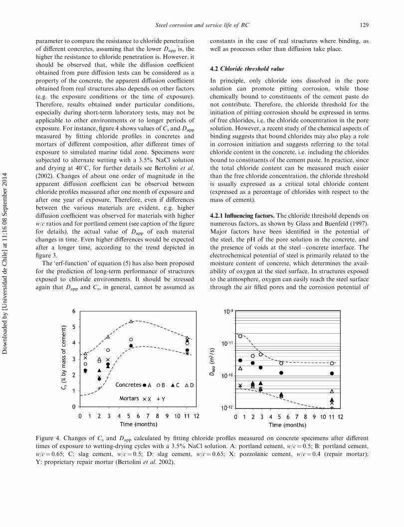
exposure. For instance, figure 4 shows values of Cs andDapp
measured by fitting chloride profiles in concretes and
mortars of different composition, after different times of
exposure to simulated marine tidal zone. Specimens were
subjected to alternate wetting with a 3.5% NaCl solution
and drying at 408C, for further details see Bertolini et al.
(2002). Changes of about one order of magnitude in the
apparent diffusion coefficient can be observed between
chloride profiles measured after one month of exposure and
after one year of exposure. Therefore, even if differences
between the various materials are evident, e.g. higher
diffusion coefficient was observed for materials with higher
w/c ratios and for portland cement (see caption of the figure
for details), the actual value of Dapp of each material
changes in time. Even higher differences would be expected
after a longer time, according to the trend depicted in
figure 3.
The ‘erf-function’ of equation (5) has also been proposed
for the prediction of long-term performance of structures
exposed to chloride environments. It should be stressed
again that Dapp and Cs, in general, cannot be assumed as
constants in the case of real structures where binding, as
well as processes other than diffusion take place.
4.2 Chloride threshold value
In principle, only chloride ions dissolved in the pore
solution can promote pitting corrosion, while those
chemically bound to constituents of the cement paste do
not contribute. Therefore, the chloride threshold for the
initiation of pitting corrosion should be expressed in terms
of free chlorides, i.e. the chloride concentration in the pore
solution. However, a recent study of the chemical aspects of
binding suggests that bound chlorides may also play a role
in corrosion initiation and suggests referring to the total
chloride content in the concrete, i.e. including the chlorides
bound to constituents of the cement paste. In practice, since
the total chloride content can be measured much easier
than the free chloride concentration, the chloride threshold
is usually expressed as a critical total chloride content
(expressed as a percentage of chlorides with respect to the
mass of cement).
4.2.1 Influencing factors. The chloride threshold depends on
numerous factors, as shown by Glass and Buenfeld (1997).
Major factors have been identified in the potential of
the steel, the pH of the pore solution in the concrete, and
the presence of voids at the steel – concrete interface. The
electrochemical potential of steel is primarily related to the
moisture content of concrete, which determines the avail-
ability of oxygen at the steel surface. In structures exposed
to the atmosphere, oxygen can easily reach the steel surface
through the air filled pores and the corrosion potential of
Figure 4. Changes of Cs and Dapp calculated by fitting chloride profiles measured on concrete specimens after different
times of exposure to wetting-drying cycles with a 3.5% NaCl solution. A: portland cement, w/c¼ 0.5; B: portland cement,
w/c¼ 0.65; C: slag cement, w/c¼ 0.5; D: slag cement, w/c¼ 0.65; X: pozzolanic cement, w/c¼ 0.4 (repair mortar);
Y: proprietary repair mortar (Bertolini et al. 2002).
Steel corrosion and service life of RC 129
Dow
nloa
ded
by [
Uni
vers
idad
de
Chi
le]
at 1
1:16
08
Sept
embe
r 20
14

the reinforcement is around 7100 to þ100 mV vs. Cu/
CuSO4. Since the first investigations on real structures were
carried out (Vassie 1984), it has been shown that the risk of
corrosion in non-carbonated concrete may be considered
low for chloride contents below 0.4% by mass of cement
(total chloride content). When a reinforced concrete
element is saturated by water, the transport of oxygen to
the steel is low in the pores filled by water and the
reinforcement reaches very negative potentials (e.g. lower
than 7500 mV vs. Cu/CuSO4). In this case, the chloride
threshold is greater than in aerated structures, sometimes
even reaching values one order of magnitude higher. For
this reason, parts of RC structures permanently immersed
in seawater rarely experience pitting corrosion initiation. A
lowering in the steel potential, and consequently an increase
in the chloride threshold value, can also be induced by an
external current that cathodically polarizes the steel, such
as in the case of the application of cathodic prevention
(Pedeferri 1995). Similarly, the chloride threshold may
increase or decrease whenever the steel is cathodically or
anodically (e.g. by macrocells) polarized respectively.
It was observed that pitting corrosion can only take place
above a critical ratio of chloride and hydroxyl ions
(Hausmann 1967). Therefore, the chloride threshold is a
function of the pH of the pore solution, which depends on
the type of cement and the additions. The chloride
threshold has also been found to be dependent on the
presence of macroscopic voids in the concrete near the steel
surface, which are normally found in real structures due to
incomplete compaction. For instance, it was shown that by
decreasing the volume of entrapped air in the steel –
concrete interfacial zone from 1.5% to 0.2% (by volume),
the chloride threshold increased from 0.2% to 2% by mass
of cement (Glass and Buenfeld 2000). The presence of air
voids, as well as crevices or microcracks, can also be an
explanation for the lower values of the chloride threshold
that are normally found in real structures compared with
those found in (usually well compacted) laboratory speci-
mens with similar materials (Page 2002).
Finally, it should be observed that, since initiation of
pitting corrosion is known to be a statistical process, the
chloride threshold can only be defined on a statistical basis
(COST 521 2003).
4.3 Corrosion propagation
Chlorides lead to a local breakdown of the protective oxide
film on the reinforcement in alkaline concrete, so that a
subsequent localized corrosion attack takes place. Once
corrosion has initiated, a very aggressive environment is
produced inside the localized corroding areas (pits), while
the protective film is maintained (and even strengthened)
on the surrounding passive surface. Corrosion inside pits
can reach very high rates of penetration (up to 1 mm per
year in wet and heavily chloride-contaminated structures)
and an unacceptable reduction in the cross-section of the
reinforcement can be reached in a relatively short time, as
shown in figure 5.
Corrosion of steel in chloride-contaminated concrete
may be further increased by macrocells between corroding
areas and passive areas (Bertolini et al. 2004). In fact, if
corroding steel is electrically connected to the surrounding
passive steel, the anodic process tends to concentrate on the
corroding steel, and the cathodic process concentrates on
the passive steel. An overall increase in the corrosion rate
on the active steel is thus induced by this macrocell action,
and it depends on the ratio between anodic and cathodic
sites and the resitivity of concrete (Schiegg et al. 2001).
Macrocells can have important implications on submerged
elements. Usually for structural elements completely and
permanently submerged in water (at least in the absence of
large voids like honeycombs or wide cracks in the cover)
the very low supply of oxygen reaching the reinforcement
keeps the steel passive, or the corrosion rate is negligible
(Arup 1983). Nevertheless, if passive rebars are present on
which, for any reason, oxygen is available, a macrocell may
form that will promote corrosion initiation and propaga-
tion on the bars in water-saturated concrete. For instance,
in hollow marine structures with air inside, corrosion may
be stimulated by a macrocell on the bars in the outer parts
by passive bars embedded in aerated concrete on the inside.
Similar conditions may arise in tunnels buried in chloride-
contaminated soils.
5. Corrosion prevention
According to recent design codes, a durable structure shall
meet given requirements of serviceability, strength and
stability throughout its intended working life, without
Figure 5. Example of a localized pitting attack on a
reinforcing bar.
130 L. Bertolini
Dow
nloa
ded
by [
Uni
vers
idad
de
Chi
le]
at 1
1:16
08
Sept
embe
r 20
14
significant loss of utility or excessive unforeseen main-
tenance (prEN 1992-1-1 2004). Therefore, long-term effects
of corrosion of steel bars should also be taken into account
in the design stage, in order to avoid the condition that any
relevant damage will be reached during the design service
life, considering the intended use of the structure, the
maintenance programme and actions. Basically, this
requires that a suitable limit state related to steel corrosion
has to be selected, in order to define the end of the service
life. Cracking or detachment of the concrete cover is
usually considered in the case of carbonation-induced
corrosion, which produces a uniform attack (as shown in
figure 1). Conversely, initiation of corrosion is often chosen
as the limit state for chloride-induced corrosion, due to the
localized nature of the pitting attack, which, once it has
initiated, can quickly bring about a marked reduction in the
cross-section of the bars, even in the absence of any
external damage on the concrete cover. Taking into
account the random nature of pitting corrosion initiation
and location, it is rather difficult to foresee the development
of damage to the structure once pitting corrosion has
initiated and, thus, the propagation period is neglected.
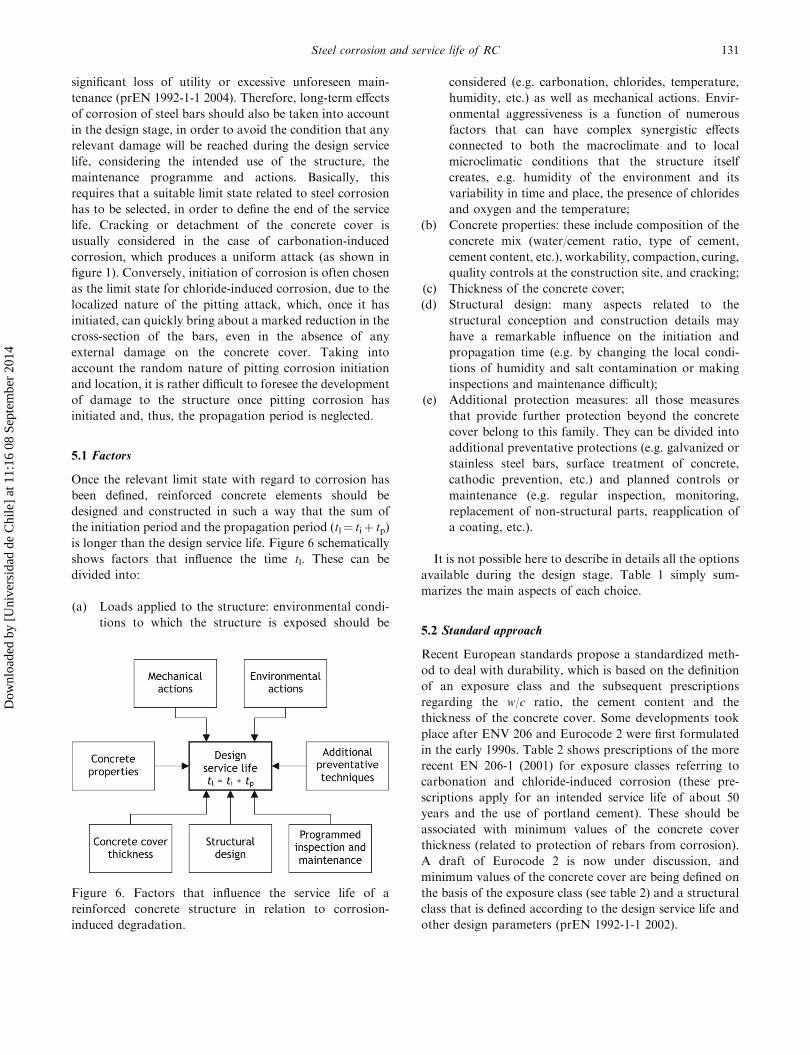
5.1 Factors
Once the relevant limit state with regard to corrosion has
been defined, reinforced concrete elements should be
designed and constructed in such a way that the sum of
the initiation period and the propagation period (tl¼ tiþ tp)
is longer than the design service life. Figure 6 schematically
shows factors that influence the time tl. These can be
divided into:
(a) Loads applied to the structure: environmental condi-
tions to which the structure is exposed should be
considered (e.g. carbonation, chlorides, temperature,
humidity, etc.) as well as mechanical actions. Envir-
onmental aggressiveness is a function of numerous
factors that can have complex synergistic effects
connected to both the macroclimate and to local
microclimatic conditions that the structure itself
creates, e.g. humidity of the environment and its
variability in time and place, the presence of chlorides
and oxygen and the temperature;
(b) Concrete properties: these include composition of the
concrete mix (water/cement ratio, type of cement,
cement content, etc.), workability, compaction, curing,
quality controls at the construction site, and cracking;
(c) Thickness of the concrete cover;
(d) Structural design: many aspects related to the
structural conception and construction details may
have a remarkable influence on the initiation and
propagation time (e.g. by changing the local condi-
tions of humidity and salt contamination or making
inspections and maintenance difficult);
(e) Additional protection measures: all those measures
that provide further protection beyond the concrete
cover belong to this family. They can be divided into
additional preventative protections (e.g. galvanized or
stainless steel bars, surface treatment of concrete,
cathodic prevention, etc.) and planned controls or
maintenance (e.g. regular inspection, monitoring,
replacement of non-structural parts, reapplication of
a coating, etc.).
It is not possible here to describe in details all the options
available during the design stage. Table 1 simply sum-
marizes the main aspects of each choice.
5.2 Standard approach
Recent European standards propose a standardized meth-
od to deal with durability, which is based on the definition
of an exposure class and the subsequent prescriptions
regarding the w/c ratio, the cement content and the
thickness of the concrete cover. Some developments took
place after ENV 206 and Eurocode 2 were first formulated
in the early 1990s. Table 2 shows prescriptions of the more
recent EN 206-1 (2001) for exposure classes referring to
carbonation and chloride-induced corrosion (these pre-
scriptions apply for an intended service life of about 50
years and the use of portland cement). These should be
associated with minimum values of the concrete cover
thickness (related to protection of rebars from corrosion).
A draft of Eurocode 2 is now under discussion, and
minimum values of the concrete cover are being defined on
the basis of the exposure class (see table 2) and a structural
class that is defined according to the design service life and
other design parameters (prEN 1992-1-1 2002).
Figure 6. Factors that influence the service life of a
reinforced concrete structure in relation to corrosion-
induced degradation.
Steel corrosion and service life of RC 131
Dow
nloa
ded
by [
Uni
vers
idad
de
Chi
le]
at 1
1:16
08
Sept
embe
r 20
14
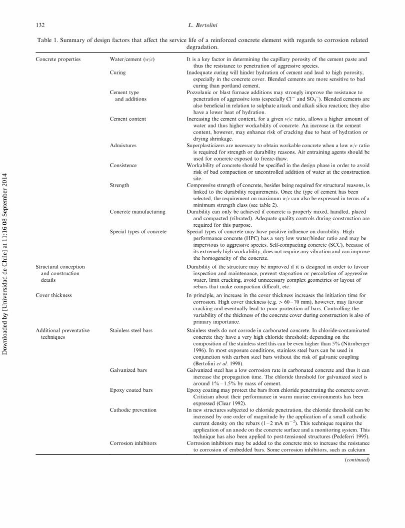
Table 1. Summary of design factors that affect the service life of a reinforced concrete element with regards to corrosion relateddegradation.
Concrete properties Water/cement (w/c) It is a key factor in determining the capillary porosity of the cement paste and
thus the resistance to penetration of aggressive species.
Curing Inadequate curing will hinder hydration of cement and lead to high porosity,
especially in the concrete cover. Blended cements are more sensitive to bad
curing than portland cement.
Cement type
and additions
Pozzolanic or blast furnace additions may strongly improve the resistance to
penetration of aggressive ions (especially Cl7 and SO4¼). Blended cements are
also beneficial in relation to sulphate attack and alkali silica reaction; they also
have a lower heat of hydration.
Cement content Increasing the cement content, for a given w/c ratio, allows a higher amount of
water and thus higher workability of concrete. An increase in the cement
content, however, may enhance risk of cracking due to heat of hydration or
drying shrinkage.
Admixtures Superplasticizers are necessary to obtain workable concrete when a low w/c ratio
is required for strength or durability reasons. Air entraining agents should be
used for concrete exposed to freeze-thaw.
Consistence Workability of concrete should be specified in the design phase in order to avoid
risk of bad compaction or uncontrolled addition of water at the construction
site.
Strength Compressive strength of concrete, besides being required for structural reasons, is
linked to the durability requirements. Once the type of cement has been
selected, the requirement on maximum w/c can also be expressed in terms of a
minimum strength class (see table 2).
Concrete manufacturing Durability can only be achieved if concrete is properly mixed, handled, placed
and compacted (vibrated). Adequate quality controls during construction are
required for this purpose.
Special types of concrete Special types of concrete may have positive influence on durability. High
performance concrete (HPC) has a very low water/binder ratio and may be
impervious to aggressive species. Self-compacting concrete (SCC), because of
its extremely high workability, does not require any vibration and can improve
the homogeneity of the concrete.
Structural conception
and construction
details
Durability of the structure may be improved if it is designed in order to favour
inspection and maintenance, prevent stagnation or percolation of aggressive
water, limit cracking, avoid unnecessary complex geometries or layout of
rebars that make compaction difficult, etc.
Cover thickness In principle, an increase in the cover thickness increases the initiation time for
corrosion. High cover thickness (e.g.4 60 – 70 mm), however, may favour
cracking and eventually lead to poor protection of bars. Controlling the
variability of the thickness of the concrete cover during construction is also of
primary importance.
Additional preventative
techniques
Stainless steel bars Stainless steels do not corrode in carbonated concrete. In chloride-contaminated
concrete they have a very high chloride threshold; depending on the
composition of the stainless steel this can be even higher than 5% (Nurnberger
1996). In most exposure conditions, stainless steel bars can be used in
conjunction with carbon steel bars without the risk of galvanic coupling
(Bertolini et al. 1998).
Galvanized bars Galvanized steel has a low corrosion rate in carbonated concrete and thus it can
increase the propagation time. The chloride threshold for galvanized steel is
around 1%–1.5% by mass of cement.
Epoxy coated bars Epoxy coating may protect the bars from chloride penetrating the concrete cover.
Criticism about their performance in warm marine environments has been
expressed (Clear 1992).
Cathodic prevention In new structures subjected to chloride penetration, the chloride threshold can be
increased by one order of magnitude by the application of a small cathodic
current density on the rebars (1 – 2 mA m72). This technique requires the
application of an anode on the concrete surface and a monitoring system. This
technique has also been applied to post-tensioned structures (Pedeferri 1995).
Corrosion inhibitors Corrosion inhibitors may be added to the concrete mix to increase the resistance
to corrosion of embedded bars. Some corrosion inhibitors, such as calcium
(continued)
132 L. Bertolini
Dow
nloa
ded
by [
Uni
vers
idad
de
Chi
le]
at 1
1:16
08
Sept
embe
r 20
14

Even though the approach proposed by European
standards is a good step towards the improvement of the
durability of RC structures, it is not (and it may not be)
exhaustive of all the aspects related to design for the
durability of reinforced concrete structures. Exposure
classes simply refer to average conditions and not to actual
microclimatic conditions throughout the structure (includ-
ing those created by the geometry of structure, where the
aggressiveness may strongly differ from the average). It is
clear that a simple set of prescriptions cannot be optimal
for all the parts of a structure. In general, it is accepted that
the recommended values for carbonation-induced corro-
sion are adequate, if associated with proper construction
practices (for instance according to ENV 13670-1 2000), to
guarantee a service life of at least 50 years. Conversely,
doubts have arisen regarding the effectiveness of recom-
mendations in table 2 for harsh chloride exposure condi-
tions, such as the splash zone of marine structures or road
structures exposed to de-icing salts. Studies on chloride
profiles obtained from old structures or laboratory tests
showed that these recommendations, even if they are
associated with prescriptions of cover thicknesses of 50 to
75 mm, are not enough to avoid pitting corrosion initiation
on the steel bars for 50 years (at least if concrete is made
with portland cement, as implicitly assumed by EN 206-1)
(Bamforth 1994b, Polder and Larbi 1995).
Moreover, the requirements provided in European
standards are simply deemed-to-satisfy rules, which do
not allow the use of a performance-based design procedure.
For instance, they do not take into consideration the effects
of additional measures, such as the use of additional
protections in the most critical parts of a structure (e.g.
joints in bridges subjected to de-icing salt contamination).
5.3 Performance-based approaches
For structures exposed to aggressive environments, which
are mainly related to the presence of chlorides, deemed-to-
satisfy rules would lead to adopting too much restrictive
prescriptions in those parts of the structure that are not
under the most aggressive exposure conditions. In this case,
a tailored design for durability would be much more
appropriate. The designer, on the basis of both the general
exposure conditions of the structure and the microclimate,
Table 1. (Continued).
nitrite, can increase the chloride threshold in sound concrete. Their
effectiveness, however, depends on the active chemical substance, its
concentration and the risk of leaching (Elsener 2001).
Surface treatment
of concrete
Organic or cement-based coatings may protect the surface of concrete and hinder
the ingress of aggressive species. Hydrophobic treatments reduce the capillary
absorption of concrete while they allow evaporation of water and transport of
gases. Periodic reapplication of the surface treatment is required (COST 521
2003).
Programmed inspection
and maintenance
Regular inspection of the structure may help to maintain a constant level of
reliability. Inspection procedures can be defined since the design phase. In
some cases, a monitoring system can be adopted, based on the application of
probes embedded in the concrete that can detect relevant events related to
corrosion of steel (COST 521 2003). Maintenance can also be programmed in
advance, for instance in order to replace non-critical parts of the structure.
Table 2. Exposure classes related to corrosion of the reinforcement (classes 2, 3 and 4) and prescriptions on concrete according to theEN 206 standard (EN 206-1 2001). The minimum strength class refers to the use of portland cement of type CEM I 32.5.
Exposure class
Description of the
environment Maximum w/c
Minimum strength
class (MPa)
Minimum cement
content (kg m73)
2. Corrosion XC1 Dry or permanently wet 0.65 C20/25 260
induced by XC2 Wet, rarely dry 0.60 C25/30 280
carbonation XC3 Moderate humidity 0.55 C30/37 280
XC4 Cyclic wet and dry 0.50 C30/37 300
3. Corrosion XD1 Moderate humidity 0.55 C30/37 300
induced by Cl7 other XD2 Wet, rarely dry 0.55 C30/37 300
than from seawater XD3 Cyclic wet and dry 0.45 C35/45 320
4. Corrosion XS1 Exposure to airborne salt 0.50 C30/37 300
induced by Cl7 XS2 Permanently submerged 0.45 C35/45 320
from seawater XS3 Tidal, splash and spray zones 0.45 C35/45 340
Steel corrosion and service life of RC 133
Dow
nloa
ded
by [
Uni
vers
idad
de
Chi
le]
at 1
1:16
08
Sept
embe
r 20
14
should design every structural element in such a way that it
can withstand the actual local conditions of exposure
during the design service life. To do this, modelling of
degradation mechanisms due to attack by a particular
aggressive agent is required, in order to estimate the
evolution of deterioration depending on factors previously
depicted in figure 6 and table 1.
In this contribution, it is not possible to refer to a large
number of models proposed in the literature to describe
corrosion-related damage of concrete structures. These
range from very simple models, e.g. those based on a square
root of time approach, to quite complex models taking into
account the basic equations describing the transport of the
aggressive species, the initiation of corrosion, and its
propagation until a limit state is reached. Often, these
models have a basic drawback in that they lack reliable
data for the parameters used in the evaluation of service
life. For instance, in the case of chloride-induced corrosion
the ‘erf-function’ approach has often been used. However,
this method can provide an acceptable evaluation of the
initiation for pitting corrosion only when reliable values are
assumed for the apparent diffusion coefficient (Dapp), the
surface chloride concentration (Cs) and the chloride
threshold value (Cth). Previously, it was illustrated that
these parameters depend on several factors that are not
easy to estimate in the design phase of a new structure. As
far as Dapp is concerned, time dependence should be
considered (see figure 2). For instance, this means that
values of Dapp obtained on short-term tests cannot be used
for the evaluation of long-term performance of real
structures (although the research of a correlation between
laboratory results and the behaviour of real systems is, at
the moment, one of the most important research topics in
the field of durability of material and structures). Further-
more, variability should be considered for the properties of
concrete and thus the previously-mentioned parameters,
and environmental actions should be considered as
probabilistically distributed.
Recently, in the framework of a European project named
Duracrete, a procedure for a quantitative evaluation of the
service life of a structure with respect to reinforcement
corrosion from the design stage has been proposed
(Duracrete 2000). This method is based on a probabilistic
approach similar to that used in the structural design. Limit
states that indicate the boundary between the desired and
the adverse behaviour of the structure are defined (e.g.
corrosion initiation or the need for repair are considered as
serviceability limit states). Environmental factors (e.g.
chloride penetration) are considered as loads acting on
the structure, while materials properties (e.g. resistance to
chloride penetration) are considered as resistances. The
stochastic nature of variables introduced in the models is
taken into consideration by evaluating average or char-
acteristic values. Design equations have been set to
calculate the failure probability of preset performances of
the structure as a function of time. The acceptable
probability has to be selected on the basis of the severity
of the adverse event occurring (limit state) (EN 1990 2002).
The Duracrete model is essentially based on the relation-
ships described earlier in x3 and x4. A square root of time
relationship from equation (1) is used to describe the
penetration of carbonation, while the ‘erf-function’ from
equation (5) is considered to describe chloride penetration.
An attempt has been made to provide statistically-based
corrective factors taking into account the role of different
variables and to correlate results of short-term tests on
concrete with the long-term performance of the structure.
This model has been applied to the design of some
structures in Europe, such as the Western Scheld tunnel
in the Netherlands (Breitenbuecher et al. 1999). Never-
theless, parameters to be introduced in the model need to
be tested on a large scale; feed back data that will be
available in the future from structures designed with the
proposed model code will be useful with this regard.
The evaluation of the performance of a given concrete
with regards to the resistance to chloride penetration is of
particular concern. This information can rarely be obtained
from previous experience, since this would require (at least)
the availability of long-term track records on the perfor-
mance of a concrete with the same composition, which was
exposed to similar exposure conditions and time as those
required for the structure under design. Even though
chloride profiles measured on real structures made of
different types of concrete and exposed to typical marine or
road conditions can be found in the literature (see for
example Rilem (2000)), this data is usually limited with
regards to the composition of the concrete, the environ-
mental conditions and the time of exposure.
Several researchers have developed short-term tests
aimed at the evaluation of the resistance of concrete to
chloride penetration. These are for instance based on
diffusion cells and on the migration or electrical resistivity
of concrete (Frederiksen 1996). The results of these
methods could be used for different purposes, e.g. the
comparison of concretes made with different mixes, the for-
mulation of prescriptions on the concrete mix, the quality
controls during the construction, and (possibly) the
estimation of the long-term performance of a given
concrete under specific exposure conditions. So far, there
is no agreement on the effectiveness and limits of these
methods. For this reason, Rilem has set up a Technical
Committee (178 TMC) dedicated to ‘testing and modelling
chloride penetration into concrete’. This Technical Com-
mittee has promoted an inter-laboratory test aimed at
studying most of the techniques proposed in the literature,
in order to assess the reproducibility of results and their
ability to differentiate the resistance of concrete to chloride
penetration.
134 L. Bertolini
Dow
nloa
ded
by [
Uni
vers
idad
de
Chi
le]
at 1
1:16
08
Sept
embe
r 20
14

5.4 Additional protection
Though the definition of quality and thickness of the
concrete cover is the first step in the design of a durable
reinforced concrete structure, other possibilities shown in
figure 6 can be considered. Under strong environmental
aggressiveness and/or when a long service life is required
(e.g. 100 years or more), the designer can take advantage of
the use of additional protections (see table 1). For example,
in chloride-bearing environments, the chloride threshold
value can be increased by using corrosion resistant steel
(e.g. stainless steel as in Bertolini and Pedeferri (2002)) or
by decreasing the steel potential by applying the technique
of cathodic prevention (Pedeferri 1995, EN 12696 2000).
Although preventative techniques increase the initial cost of
the structure, they may lead to a reduction in the overall
costs throughout the design service life. Significant reduc-
tion in the costs can be obtained by applying the additional
protection only to the most critical parts of the structure,
while protection of bars in other, less aggressive, zones is
provided only by the concrete cover. Life cycle cost analysis
is often used for the evaluation of the economical
convenience of preventative techniques.
Beyond economical aspects, the use of additional
protections may have the advantage of increasing the
reliability of the structure. It has been questioned whether
relying entirely on the protective properties of a few
centimetres thickness of the concrete cover in severe
chloride-laden environments is really the most effective
way of ensuring that embedded steel remains free from
significant corrosion for very long periods of time (Page
2002). Also, taking into account that a reinforced concrete
structure has to be designed to fulfil many functions other
than protecting embedded steel, the application of addi-
tional protections may be advantageous. The selection of
an appropriate preventative technique among those now
available should also take into account the reliability and
the track record of each technique. It is not possible to treat
this aspect in the present paper, and reference to specialized
literature (COST 509 1997, COST 521 2003, Bertolini et al.
2004) or to state-of-the art reports (Nurnberger 1996, The
Concrete Society 1998, Elsener 2001) can only be made.
However, it is useful to suggest considering the ‘fail-safe’
approach to corrosion control proposed by Page (2002),
which implies a preference for protective measures that can
be (a) easily monitored to check their continuing effective-
ness, and (b) easily reapplied or modified in the event of
premature failure to be adopted.
5.5 Quality of execution
Quality of the execution of concrete is of primary
importance in order to achieve the performance require-
ments assumed in the design of the structure. For instance,
the advantages of a lower w/c ratio or the use of blended
cement can only be achieved if concrete is properly placed,
compacted and cured. It should be stressed that poor
curing will mainly affect the concrete cover, i.e. the part
that is aimed at protecting the reinforcement, since this is
the part most susceptible to evaporation of water.
Similarly, low quality controls on the thickness of the
concrete cover may have dramatic consequences on the
time to corrosion initiation. Therefore, the designer cannot
act passively with this regard. Appropriate specifications
should be provided for composition and properties of
concrete and for the execution details. In addition, proper
quality controls at the construction must be prescribed.
These should also possibly deal with durability related
properties such as the achievement of a maximum value for
the diffusion coefficient measured according to a given test
method. The adoption of a document called a ‘birth
certificate’ has been proposed by Rostam (1999). This
document should contain all data relevant to durability
from the structural design and the construction phase.
Periodic inspection, monitoring or maintenance of the
structure could be included in this document as additional
measures required to guarantee the achievement of the
design service life.
6. Concluding remarks
This paper has introduced some of the key aspects of
carbonation and chloride-induced corrosion of steel em-
bedded in concrete, and their influence on the service life of
reinforced concrete structures. Several approaches for the
long-term prevention of corrosion have been mentioned,
showing the tools available to the designers of structures
exposed to aggressive environments. It has been shown that
prevention of degradation is a complex task that involves
competences of structural engineers, materials experts,
corrosion specialists, constructors, etc. Durability can only
arise from the cooperation among these professional
figures. This implies that nobody should think that
durability is someone else’s job, but everybody should
concentrate on the final aim of providing all the reasonable
features necessary to guarantee the design service life at the
lowest cost.
References
ACI-365, Service-life Prediction, State of the art report, American Concrete
Institute, Committee 365, 2000.
Alonso, C. and Andrade, C., Life time of rebars in carbonated concrete.
In Progress in Understanding and Prevention of Corrosion, edited by
J.M. Costa and A.D. Mercer, p. 624, 1994 (Institute of Materials:
London).
Alonso, C., Andrade, C. and Gonzales, J.A., Relation between resistivity
and corrosion rate of reinforcements in carbonated mortar made with
several cement types. Cem. Concr. Res., 1988, 18, 687 – 698.
Steel corrosion and service life of RC 135
Dow
nloa
ded
by [
Uni
vers
idad
de
Chi
le]
at 1
1:16
08
Sept
embe
r 20
14
Alonso, C., Andrade, C., Rodriguez, J., Casal, J. and Garcia, M.,
Rebar corrosion and time to cover cracking, in Proceedings of Inter-
national Conference on Concrete Across Borders, Vol. I, Odense (DK),
1994.
Arup, H., The mechanisms of the protection of steel by concrete. In
Corrosion of Reinforcement in Concrete Construction, edited by
A.P. Crane, pp. 151 – 157, 1983 (Hellis Horwood Ltd.: Chichester, UK).
Bamforth, P.B., Prediction of the onset of reinforcement corrosion due to
chloride ingress, in Proceedings of International Conference on Concrete
Across Borders, 1994.
Bamforth, P.B., Specification and design of concrete for the protection of
reinforcement in chloride-contaminated environments, in Proceedings of
International Conference on UK Corrosion and Eurocorr 94, 1994.
Bamforth, P.B. and Chapman-Andrews, J., Long term performance of RC
elements under UK coastal exposure condition, in Proceedings of
International Conference on Corrosion and corrosion protection of steel
in concrete, edited by R.N. Swamy, pp. 139 – 156, 1994 (Sheffield
Academic Press: Sheffield, UK).
Bertolini, L., Bolzoni, F., Pastore, T., and Pedeferri, P., Stray-current
induced corrosion in reinforced concrete structures. In Progress in the
Understanding and Prevention of Corrosion, edited by J.M. Costa and
A.D. Mercer, p. 568, 1993 (Institute of Materials: London).
Bertolini, L., Carsana, M., Gastaldi, M. and Berra, M., Comparison of
resistance to chloride penetration of concretes and mortars for repair, in
Third Rilem Workshop on Testing and Modelling Chloride Ingress into
Concrete, 2002.
Bertolini, L., Carsana, M. and Pedeferri, P., Influence of stray currents on
corrosion of steel in concrete, in International Conference on Eurocorr 01,
European Federation of Corrosion, 2001 (on CD-ROM).
Bertolini, L., Elsener, B., Pedeferri, P. and Polder R., Corrosion of Steel
in Concrete: Prevention, Diagnosis, Repair, 2004 (Wiley VCH:
Weinheim).
Bertolini, L., Gastaldi, M., Pastore, T., Pedeferri, M.P. and Pedeferri, P.,
Effects of galvanic coupling between carbon steel and stainless steel
reinforcement in concrete, in International Conference on Corrosion
and Rehabilitation of Reinforced Concrete Structures, Federal Highway
Administration, 1998.
Bertolini, L. and Pedeferri, P., Laboratory and field experience on the use
of stainless steel to improve durability of reinforced concrete. Corros.
Rev., 2002, 20, 129 – 152.
Bertolini, L. and Polder, R.B., Concrete Resistivity and Reinforcement
Corrosion Rate as a Function of Temperature and Humidity of the
Environment, TNO Building and Construction Research, Report No. 97-
BT-R0574, Delft (NL), 5 March 1997.
Breitenbuecher, R., Gehlen, C., Schiessl, P., Van den Hoonaard, J. and
Siemens, T., Service life design for the Western Scheldt tunnel, in Design
of Durability of Concrete, Duranet Workshop, 1999.
CEB, Durable Concrete Structures, Committee Eurointernational du Beton,
Bulletin d’information No. 183, 1992.
CEB, New Approach to Durability Design, Committee Eurointernational du
Beton, Bulletin d’information No. 238, 1997.
Clear, K.C., Effectiveness of epoxy-coated reinforcing steel. Concr. Int.,
1992, 5, 58 – 62.
Collepardi, M., Marcialis, A. and Turriziani, R., Penetration of chloride
ions into cement pastes and concretes. J. Am. Ceram. Soc., 1972, 55, 534–
535.
COST 509, Corrosion and Protection of Metals in Contact with Concrete.
Final Report, edited by R.N. Cox, R. Cigna, O. Vennesland and
T. Valente, European Commission, Directorate General Science,
Research and Development, Brussels, EUR 17608 EN, 1997.
COST 521, Corrosion of Steel in Reinforced Concrete Structures, Final
Report, edited by R. Cigna, C. Andrade, U. Nurnberger, R. Polder,
R. Weydert and E. Seitz, European Communities, Luxembourg,
Publication EUR 20599, 2003.
Duracrete, The European Union – Brite EuRam III, DuraCrete –
Probabilistic Performance Based Durability Design of Concrete Struc-
tures. Final Technical Report of Duracrete Project, Document BE95-
1347/R17, CUR, Gouda (NL), 2000.
Elsener, B., Corrosion Inhibitors for Steel in Concrete, state of the art
report, EFC Publication No. 35, The Institute of Materials, 2001 (Maney
Publishing: London).
EN 206-1, Concrete – Part 1. Specification, Performance, Production and
Conformity, European Committee for Standardization, 2001.
EN 1990, Eurocode – Basis of Structural Design, European Committee for
Standardization, 2002.
EN 12696, Cathodic Protection of Steel in Concrete – Part I: Atmo-
spherically Exposed Concrete, European Committee for Standardization,
2000.
ENV 13670-1, Execution of Concrete Structures, European Committee for
Standardization, 2000.
FIB, Durability Specifics for Prestressed Concrete Structures: Durability of
Post-tensioning Tendons, FIB Commission 5: Structural service life
aspects, TG 5.4.2, Final draft, 26 March 2004.
FIP, Report on Prestressing Steel. Stress Corrosion Cracking Resistance
Test for Prestressing Tendon, Federation Internationale de la Precon-
trainte, 1980.
Frederiksen, J.M. (Ed.), HETEK, Chloride Penetration into Concrete, state
of the art. Transport Processess, Corrosion Initiation, Tests Methods and
Prediction Models, Report No. 53, The Road Directorate, Copenhagen,
1996.
Glass, G.K. and Buenfeld, N.R., Chloride threshold level for corrosion of
steel in concrete. Corros. Sci., 1997, 39, 1001 – 1013.
Glass, G.K. and Buenfeld, N.R., The inhibitive effects of electro-
chemical treatment applied to steel in concrete. Corros. Sci., 2000, 42,
923 – 927.
Glass, G.K., Page, C.L. and Short, N.R., Factors affecting the corrosion of
steel in carbonated mortars. Corros. Sci., 1991, 32, 1283.
Gouda, V. K., Corrosion and corrosion inhibition of reinforcing steel - I.
Immersed in alkaline solutions. Br. Corros. J., 1970, 5, 198 – 203.
Hausmann, D.A., Steel corrosion in concrete, how does it occur? Mater.
Protection, 1967, 11, 19 – 23.
Isecke, B., Test Methods for Assessing the Susceptibility of Prestressing
Steels Against Hydrogen Induced Stress Corrosion Cracking, European
Federation of Corrosion, Special Publication, EFC 37, 2004, 56 pp.
Morinaga, S., Prediction of Service Lives of Reinforced Concrete Buildings
Based on Rate of Corrosion of Reinforcing Steel, Special Report of
Institute of Technology, Shimutzu Corporation, No. 23, June 1988.
Neville, A.M., Consideration of durability of concrete structures: past,
present, and future. Mater. Struct., 2001, 34, 114 – 118.
Nurnberger, U. (Ed.), Stainless Steel in Concrete, The Institute of
Materials, European Federation of Corrosion, Publication No. 18,
London, 1996.
Nurnberger, U., Corrosion induced failures of prestressing steel. Otto Graf
J., 2002, 13, 9 – 23.
Page, C.L., Corrosion and its control in reinforced concrete, in Sir F. Lea
Memorial Lecture, 26th Annual convention of the Institute of Concrete
Technology, 1998.
Page, C.L., Advances in understanding and techniques for controlling
reinforcement corrosion, in 15th International Corrosion Congress, 2002
(on CD-ROM).
Page, C.L. and Treadaway, K.W.J., Aspects of the electrochemistry of steel
in concrete. Nature, 1982, 297, 109 – 116.
Parrott, L.J., Carbonation, moisture and empty pores. Adv. Cem. Res.,
1992, 4(15), 111 – 118.
Pedeferri, P., Cathodic protection and cathodic prevention. Constr. Build.
Mater., 1995, 10, 391 – 402.
Pedeferri, P. and Bertolini, L., La Durabilita del Calcestruzzo Armato, in
Italian, 2000 (McGraw-Hill: Milan, Italy).
136 L. Bertolini
Dow
nloa
ded
by [
Uni
vers
idad
de
Chi
le]
at 1
1:16
08
Sept
embe
r 20
14
Polder, R.B. and Larbi, J.A., Investigation of concrete exposed to North
Sea water submersion for 16 years. Heron, 1995, 40(1), 31 – 56.
prEN 1992-1-1, Eurocode 2: Design of Concrete Structures – Part 1: General
Rules and Rules for Buildings, European Committee for Standardization,
2004.
Rilem, Chloride Penetration into Concrete. In Proceedings of International
RILEM Workshop, edited by L.O. Nilsson and J.P. Ollivier, 1995
(RILEM Publications: Cachan).
Rilem, Testing and Modelling the Chloride Ingress into Concrete. In
Proceedings of 2nd International RILEM Workshop, edited by
C. Andrade and J. Kropp, 2000 (RILEM Publications: Cachan).
Rostam, S., Durability in Structural concrete – Textbook on behaviour,
design and performance, FIB Bulletin 3, Vol. 3, 1999, pp. 1 – 54.
Schiegg, Y., Audergon, L., Elsener, B. and Bohni, H., Online monitoring of
the corrosion in reinforced concrete structures, in International Con-
ference on Eurocorr 01, European Federation of Corrosion, 2001 (on
CD-ROM).
Schiessl, P. (Ed.), Corrosion of Steel in Concrete, Rilem Report 60-CSC,
1988 (Chapmann & Hall: London).
The Concrete Society, Guidance on the Use of Stainless Steel Reinforcement,
Technical Report No. 51, 1998.
Tuutti, K., Corrosion of Steel in Concrete, Swedish foundation for concrete
research, Stockholm, 1982.
Vassie, P.R., Reinforcement corrosion and the durability of concrete
bridges, in Proceedings of the Institution of Civil Engineers, 1984, 76,
713.
Wierig, H.J., Long-time studies on the carbonation of concrete under
normal outdoor exposure, in Rilem Seminar on Durability of Concrete
Structures Under Normal Outdoor Exposure, 1984.
Steel corrosion and service life of RC 137
Dow
nloa
ded
by [
Uni
vers
idad
de
Chi
le]
at 1
1:16
08
Sept
embe
r 20
14