Embed Size (px)
Citation preview
Getting Started COSIMIR®
ww
w.c
osi
mir
.co
m
Short introduction into 3D Simulation and Offline Programming of robot-based workcells with COSIMIR®

Copyright © 2000 · EFR · IRF (Nov-01)
COSIMIR® Getting Started 3
Table of contents
1. Introduction.......................................................................................................................... 5 1.1 The 3D Simulation System COSIMIR®.............................................................................. 5 1.2 Text Formats...................................................................................................................... 5 1.3 System Requirements ....................................................................................................... 6 1.4 Installation Instructions ...................................................................................................... 7
2. Operating............................................................................................................................ 13 2.1 User Interface .................................................................................................................. 13 2.2 Window Types ................................................................................................................. 13
3. Modeling............................................................................................................................. 17 3.1 Model Hierarchy............................................................................................................... 17 3.2 Model Libraries ................................................................................................................ 17 3.3 Model Explorer................................................................................................................. 18 3.4 Example: Workcell Modeling ........................................................................................... 19
4. Programming ..................................................................................................................... 23 4.1 Example: Workcell Programming .................................................................................... 23
5. Simulation .......................................................................................................................... 27 5.1 Settings ............................................................................................................................ 27 5.2 Example: Workcell Simulation ......................................................................................... 28
6. Mechanisms....................................................................................................................... 29 6.1 Gripper ............................................................................................................................. 29 6.2 Conveyor Belt .................................................................................................................. 29 6.3 Push Cylinder................................................................................................................... 30 6.4 Rotary Drive..................................................................................................................... 30 6.5 Turntable.......................................................................................................................... 31 6.6 Two Way Push Cylinder .................................................................................................. 31 6.7 Turning Mover.................................................................................................................. 32 6.8 Parts Feeder .................................................................................................................... 32 6.9 Proximity Sensor.............................................................................................................. 33 6.10 Replicator......................................................................................................................... 33 6.11 Trash Can ........................................................................................................................ 33
7. Extensions ......................................................................................................................... 35 7.1 Collision Detection ........................................................................................................... 35 7.2 Sensor Simulation............................................................................................................ 35 7.3 Trajectory Generation ...................................................................................................... 35 7.4 Process Simulation .......................................................................................................... 36 7.5 PLC Simulation ................................................................................................................ 36 7.6 Camera Cruise................................................................................................................. 36 7.7 Action Object.................................................................................................................... 36
8. Appendix ............................................................................................................................ 37 8.1 Keyboard Usage .............................................................................................................. 37

Copyright © 2000 · EFR · IRF (Nov-01)
COSIMIR®Getting Started 4
8.2 Abbreviations ................................................................................................................... 38 8.3 Index ................................................................................................................................ 39
Copyright © 2000 · EFR · IRF (Nov-01)
COSIMIR® Getting Started 5
1. Introduction
This tutorial is suggested to be used for the first work with COSIMIR®. It represents a short introduction into the 3D simulation and offline programming of robot-based workcells.
1.1 The 3D Simulation System COSIMIR® COSIMIR® is the 3D-simulation system for Windows 95™/98™ and
Windows NT™/2000™ operating systems. Use COSIMIR® to plan robot-based workcells, to check the reachability of all
positions, to develop programs for robots and controllers, and to optimize the workcell layout. All movements and handling operations can be simulated to avoid collisions and to optimize cycle times. The direct download of tested programs and positions into the robot controller is completely supported.
The Modeling Extensions for COSIMIR® support the composition of robot-based workcells. Efficient modeling is provided by using component libraries containing machinery, robots, tools, conveyor belts, part feeders, etc. Free 3D modeling and import from CAD systems (e. g. AutoCAD™) are also possible.
1.2 Text Formats Different text formats are used for certain text contents as well as for keyboard
shortcuts. Text formats for plain text:
The following typographical formats are used: Text Format Used for
bold Commands, menus, and dialog boxes.
italic Enter text instead of the italic printed text.
CAPITALS Acronyms, directoy and file names. You can use lower case letters, too.
"quotation marks" Options, chapter titles, and links.
Text formats for keyboard shortcuts:
The following typographical formats are used: Text Format Means KEY1+KEY2 If you have to press two keys at the same time a plus sign
(+) is printed between the two keys. KEY1-KEY2 If you have to press two keys one after another a minus
sign (-) is printed between the two keys.
Copyright © 2000 · EFR · IRF (Nov-01)
COSIMIR®Getting Started 6
1.3 System Requirements Minimum Requirements Processor: Pentium 133 MHz Processor or higher Memory: 64 MB RAM Harddisk: 200 MB free Operating System: Windows 95™/98™
Windows NT™/2000™ Graphic Adapter: any card supported, 3D acceleration increases performance Recommended Configuration Processor: Pentium II 300 MHz Processor or higher Memory: 128 MB RAM Harddisk: 200 MB free Operating System: Windows 95™/98™
Windows NT™/2000™ Graphic Adapter: Adapter with 3D acceleration and OpenGL support High-End Configuration Processor: Pentium III 800 MHz-Processor Memory: 256 MB RAM Harddisk: 200 MB free Operating System: Windows NT™/2000™ Graphic Adapter: Adapter with 3D acceleration and OpenGL support,
GeFORCE II chip set
Copyright © 2000 · EFR · IRF (Nov-01)
COSIMIR® Getting Started 7
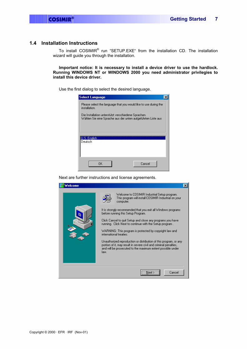
1.4 Installation Instructions To install COSIMIR® run “SETUP.EXE“ from the installation CD. The installation
wizard will guide you through the installation. Important notice: It is necessary to install a device driver to use the hardlock.
Running WINDOWS NT or WINDOWS 2000 you need administrator privilegies to install this device driver.
Use the first dialog to select the desired language.
Next are further instructions and license agreements.
Copyright © 2000 · EFR · IRF (Nov-01)
COSIMIR®Getting Started 8
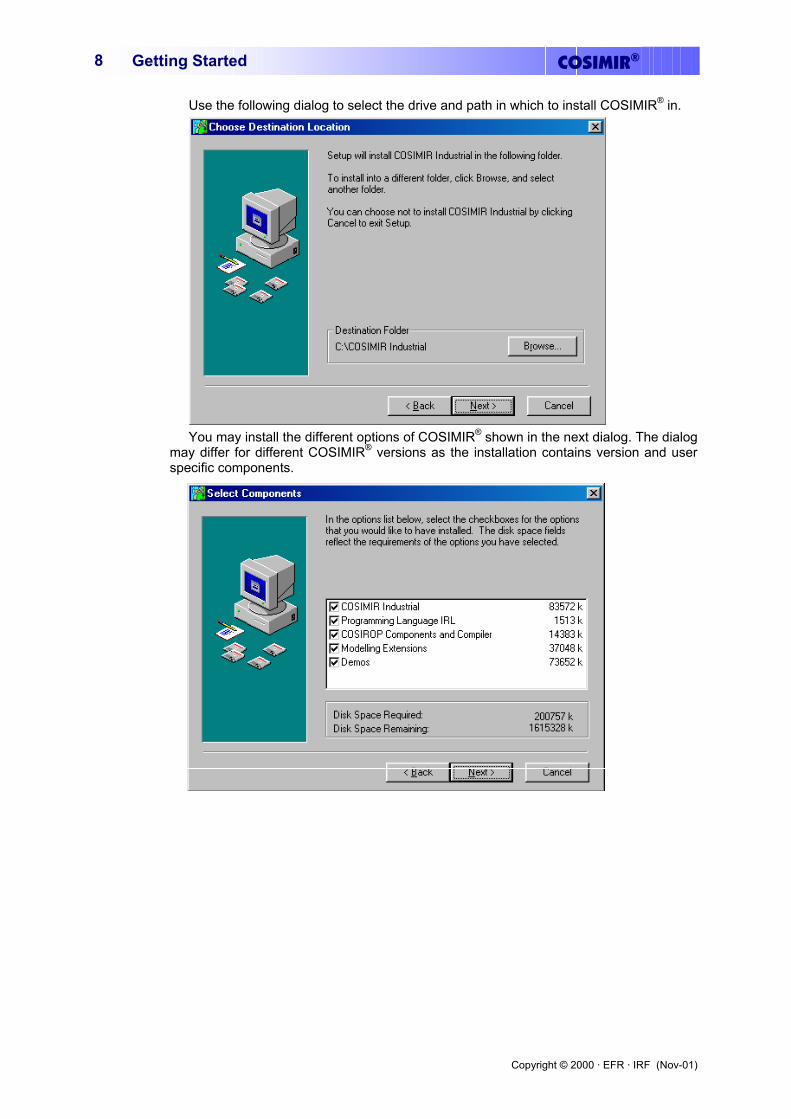
Use the following dialog to select the drive and path in which to install COSIMIR® in.
You may install the different options of COSIMIR® shown in the next dialog. The dialog
may differ for different COSIMIR® versions as the installation contains version and user specific components.
Copyright © 2000 · EFR · IRF (Nov-01)
COSIMIR® Getting Started 9
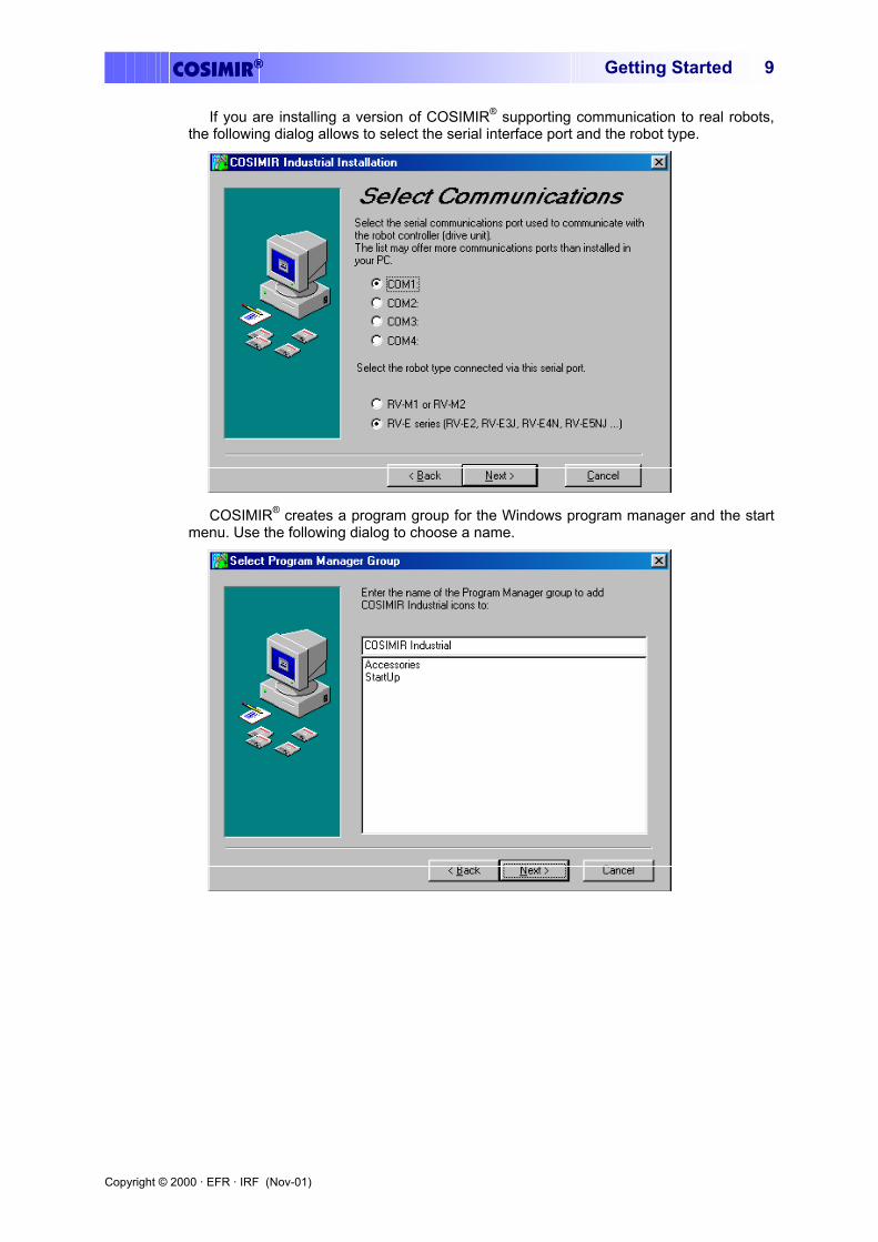
If you are installing a version of COSIMIR® supporting communication to real robots, the following dialog allows to select the serial interface port and the robot type.
COSIMIR® creates a program group for the Windows program manager and the start menu. Use the following dialog to choose a name.
Copyright © 2000 · EFR · IRF (Nov-01)
COSIMIR®Getting Started 10
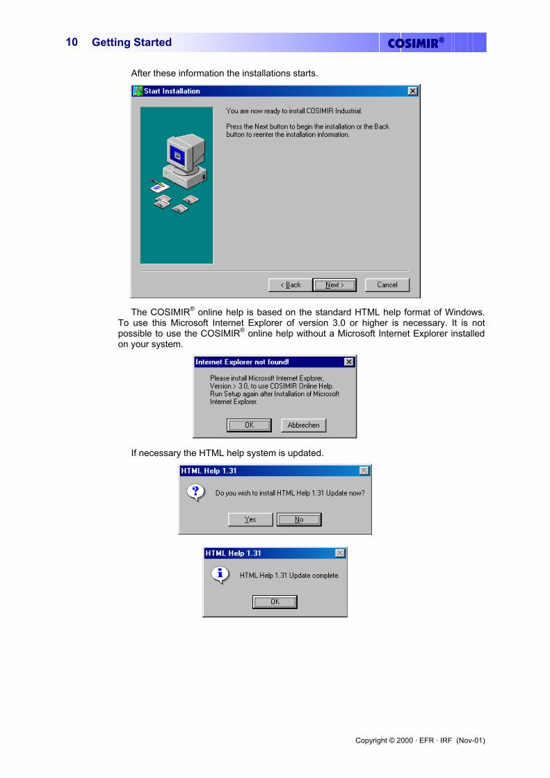
After these information the installations starts.
The COSIMIR® online help is based on the standard HTML help format of Windows. To use this Microsoft Internet Explorer of version 3.0 or higher is necessary. It is not possible to use the COSIMIR® online help without a Microsoft Internet Explorer installed on your system.
If necessary the HTML help system is updated.
Copyright © 2000 · EFR · IRF (Nov-01)
COSIMIR® Getting Started 11
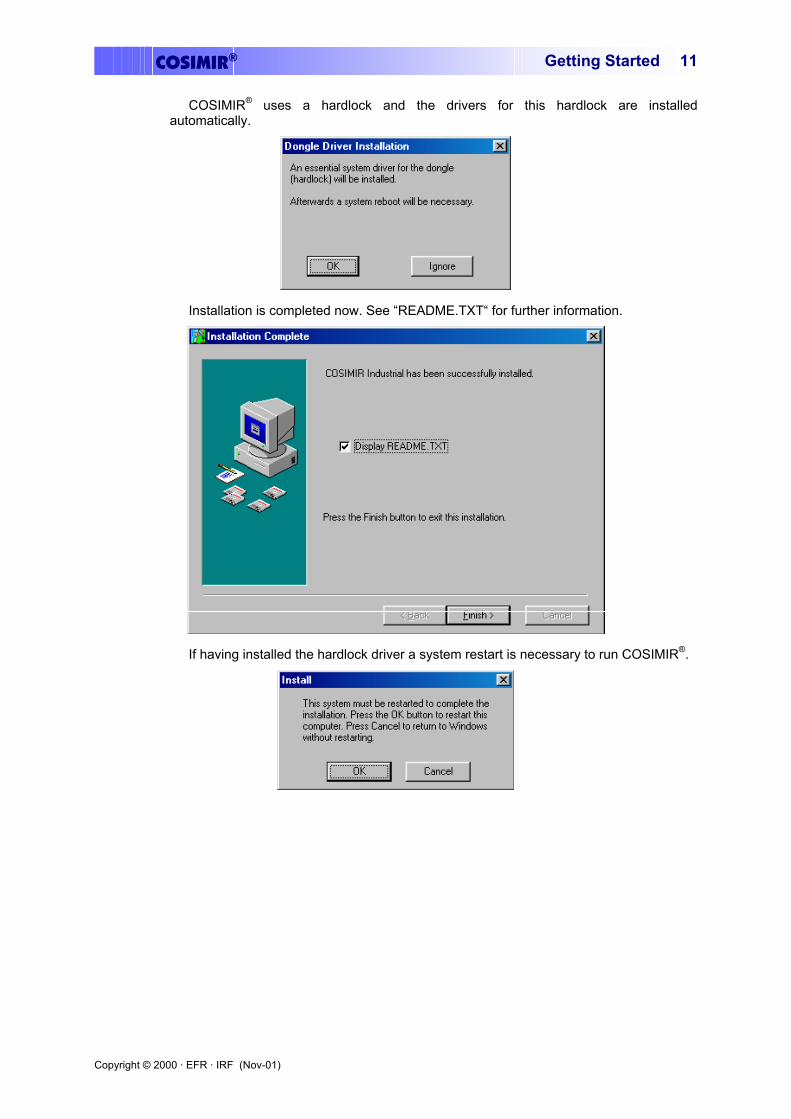
COSIMIR® uses a hardlock and the drivers for this hardlock are installed automatically.
Installation is completed now. See “README.TXT“ for further information.
If having installed the hardlock driver a system restart is necessary to run COSIMIR®.

Copyright © 2000 · EFR · IRF (Nov-01)
COSIMIR®Getting Started 12
Copyright © 2000 · EFR · IRF (Nov-01)
COSIMIR® Getting Started 13
2. Operating
This chapter shows the first steps in using COSIMR®.
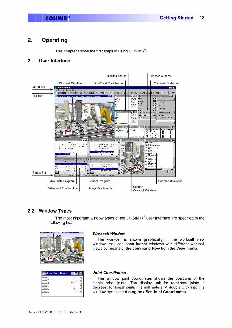
2.1 User Interface
Mitsubishi Program
Mitsubishi Position List
Adept Program
Adept Position List
User Input/Output
SecondWorkcell Window
Workcell Window
Inputs/Outputs
Joint/World Coordinates Controller Selection
TeachIn Window
Menu Bar
Toolbar
Status Bar
2.2 Window Types The most important window types of the COSIMIR® user interface are specified in the
following list.
Workcell Window The workcell is shown graphically in the workcell view
window. You can open further windows with different workcell views by means of the command New from the View menu.
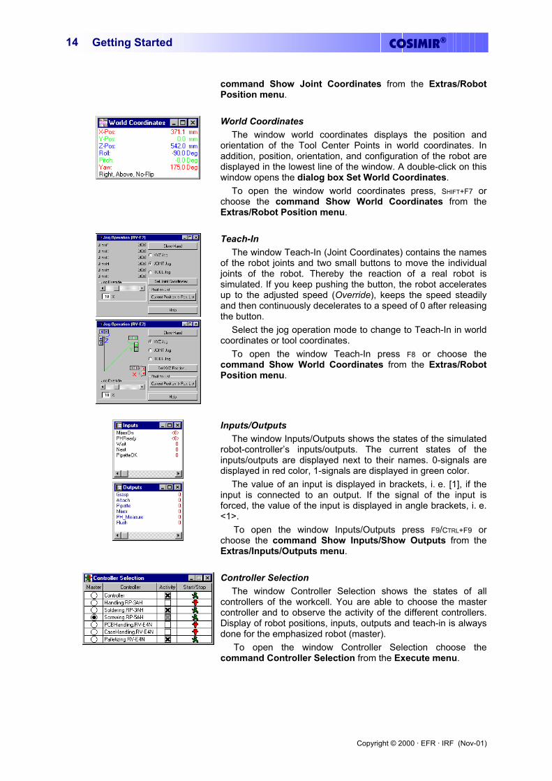
Joint Coordinates The window joint coordinates shows the positions of the
single robot joints. The display unit for rotational joints is degrees, for linear joints it is millimeters. A double click into this window opens the dialog box Set Joint Coordinates.
Copyright © 2000 · EFR · IRF (Nov-01)
COSIMIR®Getting Started 14
command Show Joint Coordinates from the Extras/Robot Position menu.
World Coordinates The window world coordinates displays the position and
orientation of the Tool Center Points in world coordinates. In addition, position, orientation, and configuration of the robot are displayed in the lowest line of the window. A double-click on this window opens the dialog box Set World Coordinates.
To open the window world coordinates press, SHIFT+F7 or choose the command Show World Coordinates from the Extras/Robot Position menu.
Teach-In The window Teach-In (Joint Coordinates) contains the names
of the robot joints and two small buttons to move the individual joints of the robot. Thereby the reaction of a real robot is simulated. If you keep pushing the button, the robot accelerates up to the adjusted speed (Override), keeps the speed steadily and then continuously decelerates to a speed of 0 after releasing the button.
Select the jog operation mode to change to Teach-In in world coordinates or tool coordinates.
To open the window Teach-In press F8 or choose the command Show World Coordinates from the Extras/Robot Position menu.
Inputs/Outputs The window Inputs/Outputs shows the states of the simulated
robot-controller’s inputs/outputs. The current states of the inputs/outputs are displayed next to their names. 0-signals are displayed in red color, 1-signals are displayed in green color.
The value of an input is displayed in brackets, i. e. [1], if the input is connected to an output. If the signal of the input is forced, the value of the input is displayed in angle brackets, i. e. <1>.
To open the window Inputs/Outputs press F9/CTRL+F9 or choose the command Show Inputs/Show Outputs from the Extras/Inputs/Outputs menu.
Controller Selection The window Controller Selection shows the states of all
controllers of the workcell. You are able to choose the master controller and to observe the activity of the different controllers. Display of robot positions, inputs, outputs and teach-in is always done for the emphasized robot (master).
To open the window Controller Selection choose the command Controller Selection from the Execute menu.
Copyright © 2000 · EFR · IRF (Nov-01)
COSIMIR® Getting Started 15
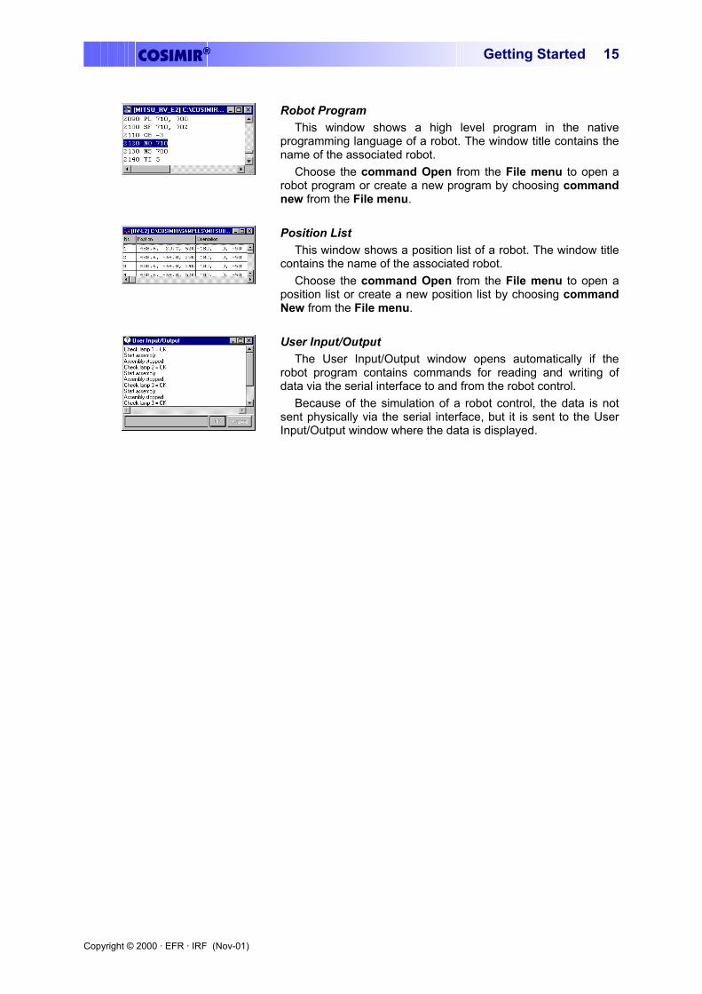
Robot Program This window shows a high level program in the native
programming language of a robot. The window title contains the name of the associated robot.
Choose the command Open from the File menu to open a robot program or create a new program by choosing command new from the File menu.
Position List This window shows a position list of a robot. The window title
contains the name of the associated robot. Choose the command Open from the File menu to open a
position list or create a new position list by choosing command New from the File menu.
User Input/Output The User Input/Output window opens automatically if the
robot program contains commands for reading and writing of data via the serial interface to and from the robot control.
Because of the simulation of a robot control, the data is not sent physically via the serial interface, but it is sent to the User Input/Output window where the data is displayed.

Copyright © 2000 · EFR · IRF (Nov-01)
COSIMIR®Getting Started 16
Copyright © 2000 · EFR · IRF (Nov-01)
COSIMIR® Getting Started 17
3. Modeling
There are several tools (i. e. model libraries and the Model Explorer for COSIMIR®) providing a comfortable modeling of robot-based workcells. By means of a simple example workcell, a short introduction in workcell modeling is given in this chapter.
3.1 Model Hierarchy The COSIMIR® model hierarchy contains the following element types:
Objects The highest unit in the element structure are the objects.
Example: A robot is an object.
Sections Sections are assigned to objects. One degree-of-freedom can be associated to each section that is moveable relatively to the previous section.
Example: Each joint of a robot is a section.
Hulls Hulls are assigned to sections and are responsible for the graphical representation.
Example: A face, a box or a polyhedron are hulls.
Gripper Points An object needs a gripper point to grasp other objects. Gripper points are assigned to sections.
Example: At the flange of a robot a gripper point is modeled.
Grip Points To be grasped by another object an object needs a grip point. Grip points are assigned to sections.
Example: A grip point is associated to a work piece that has to be grasped.
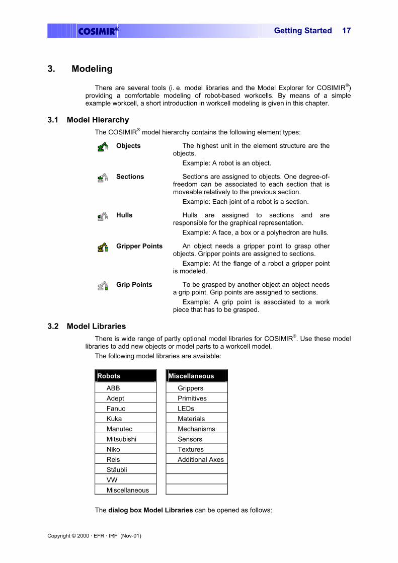
3.2 Model Libraries There is wide range of partly optional model libraries for COSIMIR®. Use these model
libraries to add new objects or model parts to a workcell model. The following model libraries are available: Robots Miscellaneous
ABB Grippers Adept Primitives Fanuc LEDs Kuka Materials Manutec Mechanisms Mitsubishi Sensors Niko Textures Reis Additional AxesStäubli VW Miscellaneous
The dialog box Model Libraries can be opened as follows:
Copyright © 2000 · EFR · IRF (Nov-01)
COSIMIR®Getting Started 18
Menu Execute/Model Libraries Toolbar
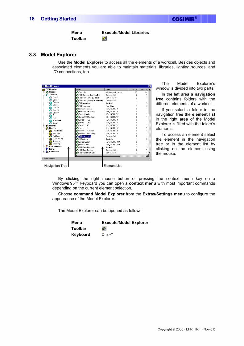
3.3 Model Explorer Use the Model Explorer to access all the elements of a workcell. Besides objects and
associated elements you are able to maintain materials, libraries, lighting sources, and I/O connections, too.
Navigation Tree Element List
The Model Explorer’s window is divided into two parts.
In the left area a navigation tree contains folders with the different elements of a workcell.
If you select a folder in the navigation tree the element list in the right area of the Model Explorer is filled with the folder’s elements.
To access an element select the element in the navigation tree or in the element list by clicking on the element using the mouse.
By clicking the right mouse button or pressing the context menu key on a Windows 95™ keyboard you can open a context menu with most important commands depending on the current element selection.
Choose command Model Explorer from the Extras/Settings menu to configure the appearance of the Model Explorer.
The Model Explorer can be opened as follows:
Menu Execute/Model Explorer Toolbar Keyboard CTRL+T

Copyright © 2000 · EFR · IRF (Nov-01)
COSIMIR® Getting Started 19
3.4 Example: Workcell Modeling In this chapter modeling of a simple workcell is described step by step. Programming
and simulation of this workcell are described in the next chapters.
Choose command New Workcell from the File menu to create a new workcell. Specify the filename (e. g. “Example.mod”) for the new workcell.
After creating the new workcell you are able to specify a different workcell name as well as properties for the workcell (e. g. background color, floor color, and floor size). Use the dialog Properties for workcell while the workcell name is selected in the Model Explorer to change workcell properties.
Open dialog box Model Libraries by choosing command Model Libraries from the Execute menu or clicking the button in the toolbar.
Select the Mitsubishi Robot RV-2AJ from library “Mitsubishi Robots” and click Add.
The robot is the first object in the workcell and is displayed in the Model Explorer.
In the Model Explorer select the digital Output (Index 000) of the robot and press F2 to activate and to rename the output to “Grasp”.
Copyright © 2000 · EFR · IRF (Nov-01)
COSIMIR®Getting Started 20
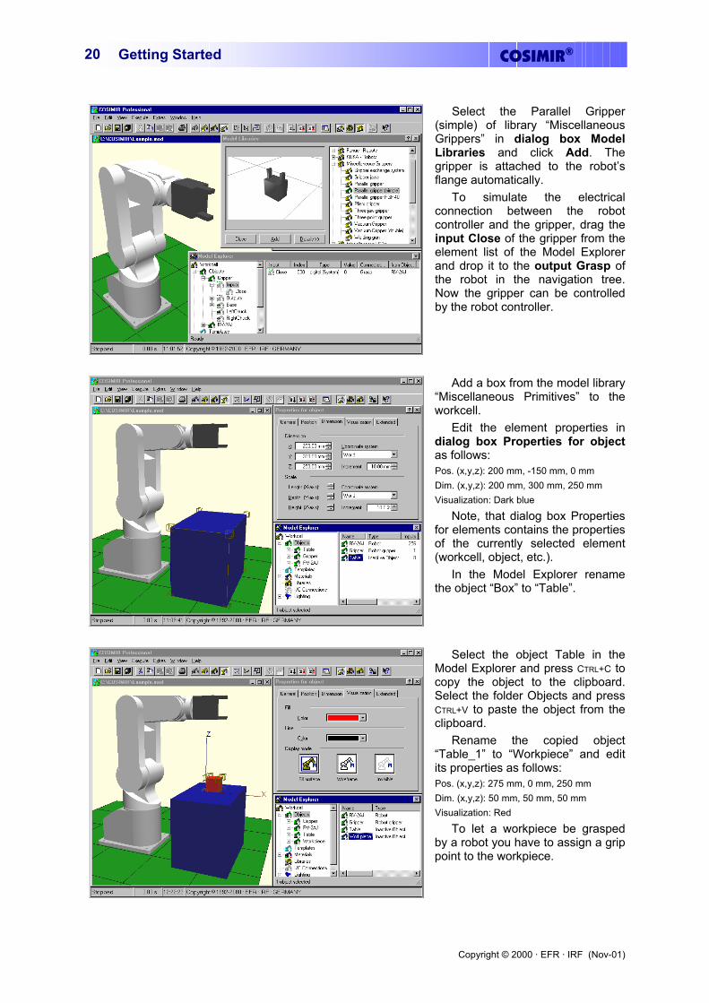
Select the Parallel Gripper (simple) of library “Miscellaneous Grippers” in dialog box Model Libraries and click Add. The gripper is attached to the robot’s flange automatically.
To simulate the electrical connection between the robot controller and the gripper, drag the input Close of the gripper from the element list of the Model Explorer and drop it to the output Grasp of the robot in the navigation tree. Now the gripper can be controlled by the robot controller.
Add a box from the model library “Miscellaneous Primitives” to the workcell.
Edit the element properties in dialog box Properties for object as follows: Pos. (x,y,z): 200 mm, -150 mm, 0 mm Dim. (x,y,z): 200 mm, 300 mm, 250 mm Visualization: Dark blue
Note, that dialog box Properties for elements contains the properties of the currently selected element (workcell, object, etc.).
In the Model Explorer rename the object “Box” to “Table”.
Select the object Table in the Model Explorer and press CTRL+C to copy the object to the clipboard. Select the folder Objects and press CTRL+V to paste the object from the clipboard.
Rename the copied object “Table_1” to “Workpiece” and edit its properties as follows: Pos. (x,y,z): 275 mm, 0 mm, 250 mm Dim. (x,y,z): 50 mm, 50 mm, 50 mm Visualization: Red
To let a workpiece be grasped by a robot you have to assign a grip point to the workpiece.
Copyright © 2000 · EFR · IRF (Nov-01)
COSIMIR® Getting Started 21
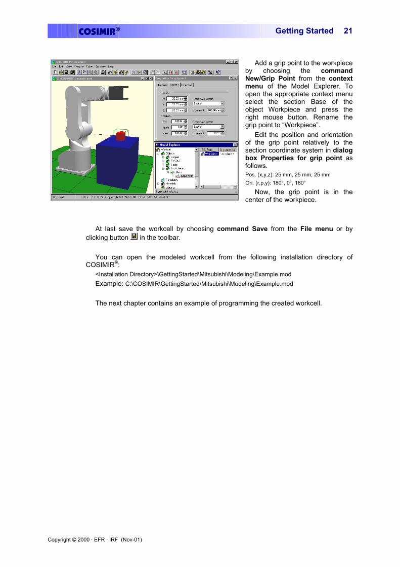
Add a grip point to the workpiece by choosing the command New/Grip Point from the context menu of the Model Explorer. To open the appropriate context menu select the section Base of the object Workpiece and press the right mouse button. Rename the grip point to “Workpiece”.
Edit the position and orientation of the grip point relatively to the section coordinate system in dialog box Properties for grip point as follows. Pos. (x,y,z): 25 mm, 25 mm, 25 mm Ori. (r,p,y): 180°, 0°, 180°
Now, the grip point is in the center of the workpiece.
At last save the workcell by choosing command Save from the File menu or by
clicking button in the toolbar. You can open the modeled workcell from the following installation directory of
COSIMIR®: <Installation Directory>\GettingStarted\Mitsubishi\Modeling\Example.mod Example: C:\COSIMIR\GettingStarted\Mitsubishi\Modeling\Example.mod The next chapter contains an example of programming the created workcell.

Copyright © 2000 · EFR · IRF (Nov-01)
COSIMIR®Getting Started 22
Copyright © 2000 · EFR · IRF (Nov-01)
COSIMIR® Getting Started 23
4. Programming
For programming of robots the native programming language of the robots is used in COSIMIR®.
4.1 Example: Workcell Programming This example shows the programming of the robot. The workcell modeled in the
previous chapter is used.
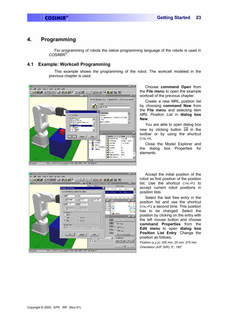
Choose command Open from the File menu to open the example workcell of the previous chapter.
Create a new MRL position list by choosing command New from the File menu and selecting item MRL Position List in dialog box New.
You are able to open dialog box new by clicking button in the toolbar or by using the shortcut CTRL+N.
Close the Model Explorer and the dialog box Properties for elements.
Accept the initial position of the robot as first position of the position list. Use the shortcut CTRL+F2 to accept current robot positions in position lists.
Select the last free entry in the position list and use the shortcut CTRL+F2 a second time. This position has to be changed. Select the position by clicking on the entry with the left mouse button and choose command Properties from the Edit menu to open dialog box Position List Entry. Change the position as follows: Position (x,y,z): 300 mm, 25 mm, 275 mm Orientation (A/P, B/R): 0°, 180°
Copyright © 2000 · EFR · IRF (Nov-01)
COSIMIR®Getting Started 24
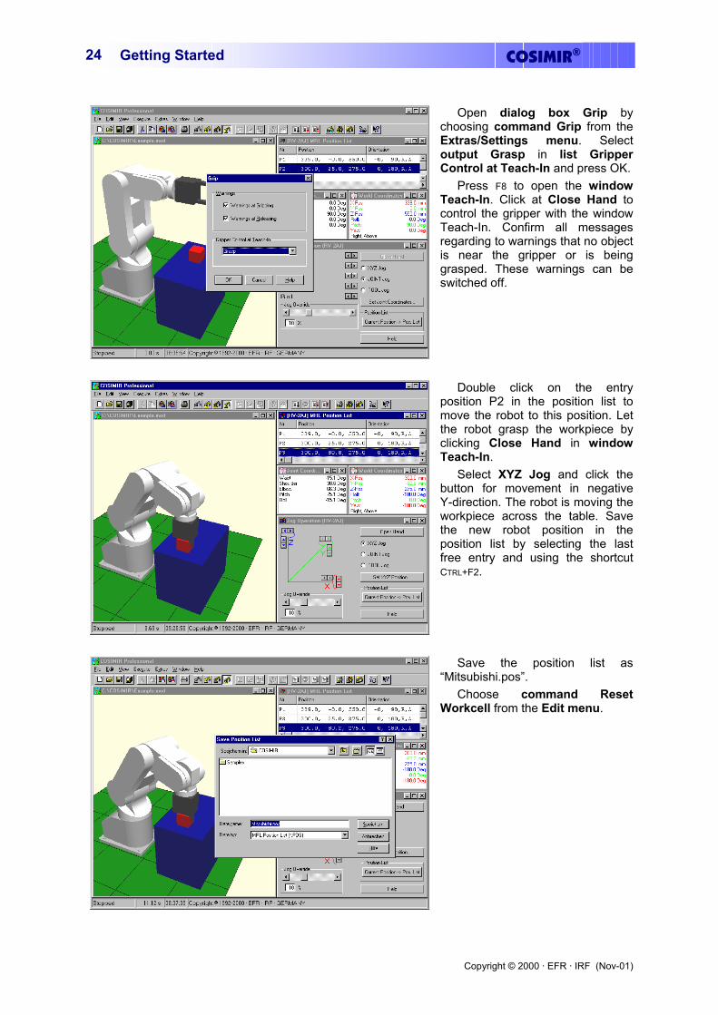
Open dialog box Grip by choosing command Grip from the Extras/Settings menu. Select output Grasp in list Gripper Control at Teach-In and press OK.
Press F8 to open the window Teach-In. Click at Close Hand to control the gripper with the window Teach-In. Confirm all messages regarding to warnings that no object is near the gripper or is being grasped. These warnings can be switched off.
Double click on the entry position P2 in the position list to move the robot to this position. Let the robot grasp the workpiece by clicking Close Hand in window Teach-In.
Select XYZ Jog and click the button for movement in negative Y-direction. The robot is moving the workpiece across the table. Save the new robot position in the position list by selecting the last free entry and using the shortcut CTRL+F2.
Save the position list as “Mitsubishi.pos”.
Choose command Reset Workcell from the Edit menu.
Copyright © 2000 · EFR · IRF (Nov-01)
COSIMIR® Getting Started 25
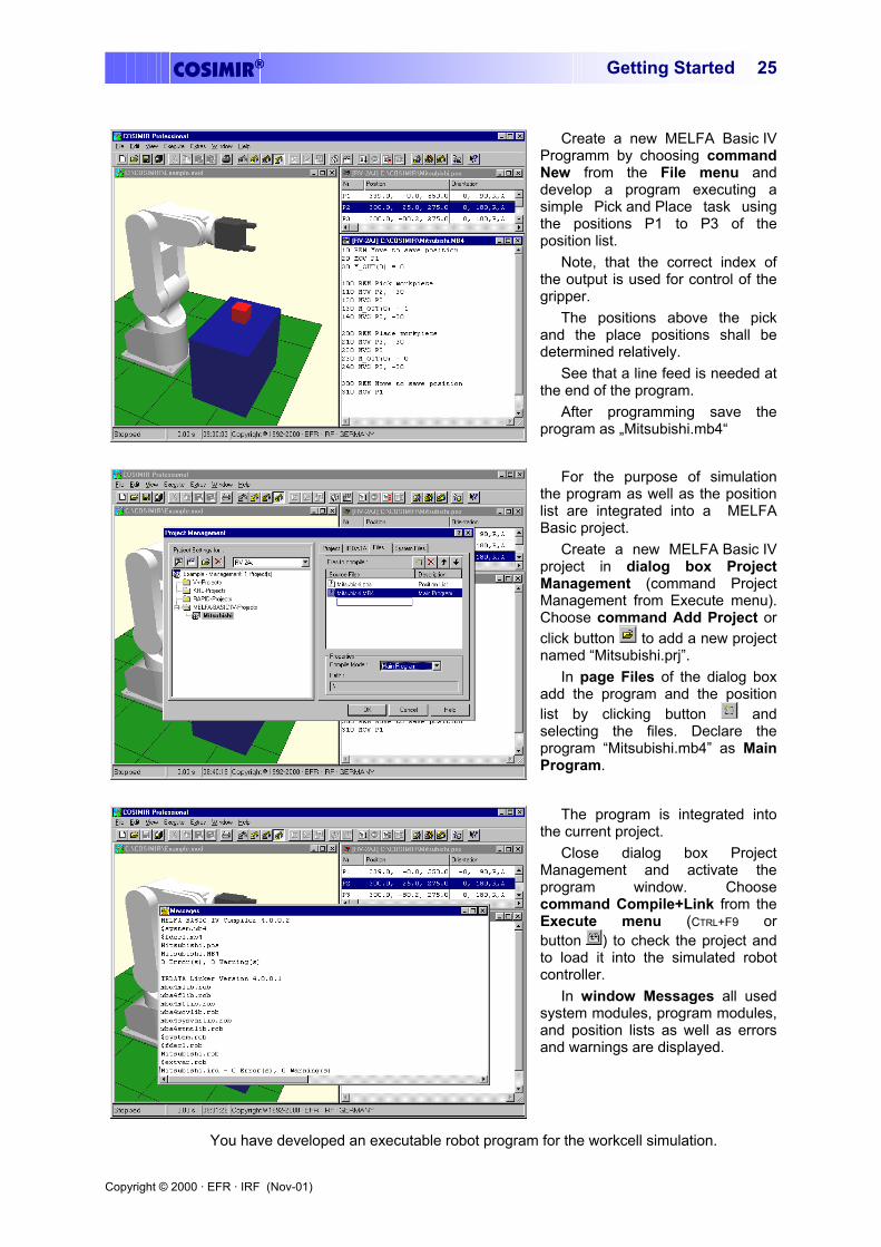
Create a new MELFA Basic IV Programm by choosing command New from the File menu and develop a program executing a simple Pick and Place task using the positions P1 to P3 of the position list.
Note, that the correct index of the output is used for control of the gripper.
The positions above the pick and the place positions shall be determined relatively.
See that a line feed is needed at the end of the program.
After programming save the program as „Mitsubishi.mb4“
For the purpose of simulation the program as well as the position list are integrated into a MELFA Basic project.
Create a new MELFA Basic IV project in dialog box Project Management (command Project Management from Execute menu). Choose command Add Project or click button to add a new project named “Mitsubishi.prj”.
In page Files of the dialog box add the program and the position list by clicking button and selecting the files. Declare the program “Mitsubishi.mb4” as Main Program.
The program is integrated into the current project.
Close dialog box Project Management and activate the program window. Choose command Compile+Link from the Execute menu (CTRL+F9 or button ) to check the project and to load it into the simulated robot controller.
In window Messages all used system modules, program modules, and position lists as well as errors and warnings are displayed.
You have developed an executable robot program for the workcell simulation.
Copyright © 2000 · EFR · IRF (Nov-01)
COSIMIR®Getting Started 26
You can open the programmed workcell from the following installation directory of
COSIMIR®: <Installation Directory>\GettingStarted\Mitsubishi\Programming\Example.mod Example: C:\COSIMIR\GettingStarted\Mitsubishi\Programming\Example.mod The next chapter contains an example of simulating the modeled and programmed
workcell.
Copyright © 2000 · EFR · IRF (Nov-01)
COSIMIR® Getting Started 27
5. Simulation
This chapter contains the simulation of programs developed offline in COSIMIR®.
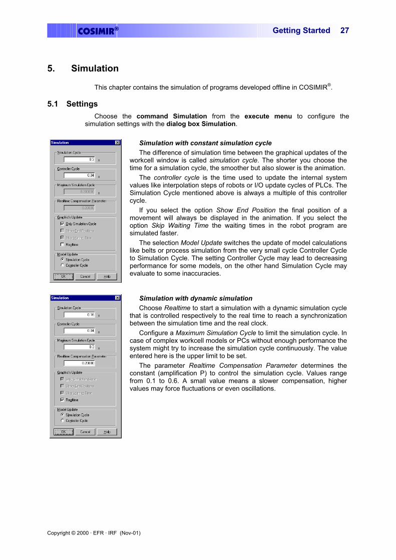
5.1 Settings Choose the command Simulation from the execute menu to configure the
simulation settings with the dialog box Simulation.
Simulation with constant simulation cycle The difference of simulation time between the graphical updates of the
workcell window is called simulation cycle. The shorter you choose the time for a simulation cycle, the smoother but also slower is the animation.
The controller cycle is the time used to update the internal system values like interpolation steps of robots or I/O update cycles of PLCs. The Simulation Cycle mentioned above is always a multiple of this controller cycle.
If you select the option Show End Position the final position of a movement will always be displayed in the animation. If you select the option Skip Waiting Time the waiting times in the robot program are simulated faster.
The selection Model Update switches the update of model calculations like belts or process simulation from the very small cycle Controller Cycle to Simulation Cycle. The setting Controller Cycle may lead to decreasing performance for some models, on the other hand Simulation Cycle may evaluate to some inaccuracies.
Simulation with dynamic simulation Choose Realtime to start a simulation with a dynamic simulation cycle
that is controlled respectively to the real time to reach a synchronization between the simulation time and the real clock.
Configure a Maximum Simulation Cycle to limit the simulation cycle. In case of complex workcell models or PCs without enough performance the system might try to increase the simulation cycle continuously. The value entered here is the upper limit to be set.
The parameter Realtime Compensation Parameter determines the constant (amplification P) to control the simulation cycle. Values range from 0.1 to 0.6. A small value means a slower compensation, higher values may force fluctuations or even oscillations.

Copyright © 2000 · EFR · IRF (Nov-01)
COSIMIR®Getting Started 28
5.2 Example: Workcell Simulation Open the example workcell of the previous chapters.
To start simulation choose command Start from the Execute menu.
The program is simulated step by step. The simulation time is displayed in the status bar. Because of the source code sequence trace the currently executed command is highlighted in the program window.
Before you start simulation a second time choose command Reset Workcell from the Edit menu. This command resets all objects as well as the robot
Copyright © 2000 · EFR · IRF (Nov-01)
COSIMIR® Getting Started 29
6. Mechanisms
In COSIMIR® the simulation of so called base mechanisms is a powerful feature for simulation of workcells. A mechanism is assigned to an object using the object’s type. Depending on the mechanism the object structure (concerning number of I/Os, number and configuration of sections and joints) is given. The mechanism can only be simulated correctly if the given object structure exists.
To model a mechanism, use the model libraries. Add an object with a mechanism to the workcell to guarantee that the object structure is correct. Afterwards, change the shape as well as the dynamics and I/O names of the object to model your own mechanism.
Please note that to control any of the mechanisms the input values have to change from low to high to start the mechanism. Moreover the output values containing the state of the mechanisms are only updated if the outputs are connected to an input.
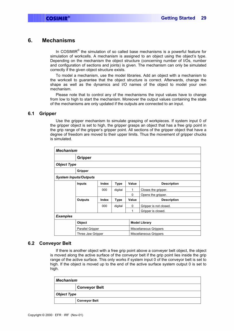
6.1 Gripper Use the gripper mechanism to simulate grasping of workpieces. If system input 0 of
the gripper object is set to high, the gripper grasps an object that has a free grip point in the grip range of the gripper’s gripper point. All sections of the gripper object that have a degree of freedom are moved to their upper limits. Thus the movement of gripper chucks is simulated.
Mechanism Gripper Object Type Gripper
System Inputs/Outputs Index Type Value Description
1 Closes the gripper.
Inputs
000 digital 0 Opens the gripper.
Index Type Value Description
0 Gripper is not closed.
Outputs
000 digital 1 Gripper is closed.
Examples
Object Model Library
Parallel Gripper Miscellaneous Grippers
Three Jaw Gripper Miscellaneous Grippers
6.2 Conveyor Belt If there is another object with a free grip point above a conveyer belt object, the object
is moved along the active surface of the conveyor belt if the grip point lies inside the grip range of the active surface. This only works if system input 0 of the conveyor belt is set to high. If the object is moved up to the end of the active surface system output 0 is set to high.
Mechanism Conveyor Belt Object Type Conveyor Belt

Copyright © 2000 · EFR · IRF (Nov-01)
COSIMIR®Getting Started 30
System Inputs/Outputs Index Type Value Description
1 Switches the conveyor belt on. 000 digital 0 Switches the conveyor belt off. 1 Conveyor belt transports backwards.
Inputs
001 digital 0 Conveyor belt transports forward.
Index Type Value Description
0 There is no object at conveyor’s end.
Outputs
000 digital 1 There is an object at conveyor’s end.
Examples
Object Model Library
Conveyor Belt Miscellaneous Mechanisms
6.3 Push Cylinder The push cylinder is extended if system input 0 is set to high. If there is an object with
a free grip point in the grip range of the push cylinder’s gripper point the object is moved by the push cylinder. The push cylinder is retracted if system input 0 is set to low.
Mechanism Push Cylinder Object Type Push Cylinder
System Inputs/Outputs Index Type Value Description
1 Extends the push cylinder.
Inputs
000 digital 0 Retracts the push cylinder.
Index Type Value Description
0 Push cylinder is not extended.
Outputs
000 digital 1 Push cylinder is extended.
Examples
Object Model Library
Push Cylinder Miscellaneous Mechanisms
6.4 Rotary Drive The mechanism rotary drive is based on the push cylinder mechanism. Mechanism Rotary Drive Object Type Rotary Drive
System Inputs/Outputs Index Type Value Description
1 Rotary Drive moves to upper limit.
Inputs
000 digital 0 Rotary Drive moves to lower limit.
Index Type Value Description
0 Rotary Drive is not at upper limit.
Outputs
000 digital 1 Rotary Drive is at upper limit.
Examples

Copyright © 2000 · EFR · IRF (Nov-01)
COSIMIR® Getting Started 31
Object Model Library
Rotary Drive Miscellaneous Mechanisms
6.5 Turntable All axes of turntable object are moved to the upper limits if system input 0 is set to
high. If there is an object with a free grip point inside the grip range of the turntable’s active surface the object is moved with the turntable.
Mechanism Turntable Object Type Turntable
System Inputs/Outputs Index Type Value Description
1 Turns the turntable.
Inputs
000 digital 0 -
Index Type Value Description
0 Turntable is moving.
Outputs
000 digital 1 Turntable stand still.
Examples
Object Model Library
Turntable Miscellaneous Mechanisms
6.6 Two Way Push Cylinder The function of the two way push cylinder is similar to the function of the push
cylinder. For the purpose of control there are two system inputs. According to this there are two system outputs for the cylinder’s state.
Mechanism Two Way Push Cylinder Object Type Two Way Push Cylinder
System Inputs/Outputs Index Type Value Description
1 Extends the push cylinder. 000 digital 0 - 1 Retracts the push cylinder.
Inputs
001 digital 0 -
Index Type Value Description
0 Push cylinder is not extended. 000 digital 1 Push cylinder is extended. 0 Push cylinder is not retracted.
Outputs
001 digital 1 Push cylinder is retracted.
Examples
Object Model Library
Two Way Push Cylinder Miscellaneous Mechanisms
Copyright © 2000 · EFR · IRF (Nov-01)
COSIMIR®Getting Started 32
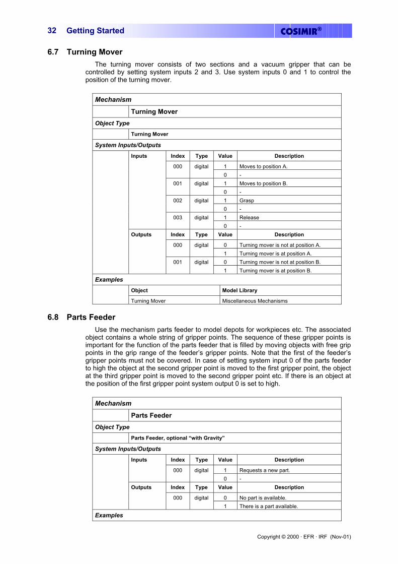
6.7 Turning Mover The turning mover consists of two sections and a vacuum gripper that can be
controlled by setting system inputs 2 and 3. Use system inputs 0 and 1 to control the position of the turning mover.
Mechanism Turning Mover Object Type Turning Mover
System Inputs/Outputs Index Type Value Description
1 Moves to position A. 000 digital 0 - 1 Moves to position B. 001 digital 0 - 1 Grasp 002 digital 0 - 1 Release
Inputs
003 digital 0 -
Index Type Value Description
0 Turning mover is not at position A. 000 digital 1 Turning mover is at position A. 0 Turning mover is not at position B.
Outputs
001 digital 1 Turning mover is at position B.
Examples
Object Model Library
Turning Mover Miscellaneous Mechanisms
6.8 Parts Feeder Use the mechanism parts feeder to model depots for workpieces etc. The associated
object contains a whole string of gripper points. The sequence of these gripper points is important for the function of the parts feeder that is filled by moving objects with free grip points in the grip range of the feeder’s gripper points. Note that the first of the feeder’s gripper points must not be covered. In case of setting system input 0 of the parts feeder to high the object at the second gripper point is moved to the first gripper point, the object at the third gripper point is moved to the second gripper point etc. If there is an object at the position of the first gripper point system output 0 is set to high.
Mechanism Parts Feeder Object Type Parts Feeder, optional “with Gravity”
System Inputs/Outputs Index Type Value Description
1 Requests a new part.
Inputs
000 digital 0 -
Index Type Value Description
0 No part is available.
Outputs
000 digital 1 There is a part available.
Examples

Copyright © 2000 · EFR · IRF (Nov-01)
COSIMIR® Getting Started 33
Object Model Library
Parts Feeder 1 Miscellaneous Mechanisms
Parts Feeder 2 Miscellaneous Mechanisms
6.9 Proximity Sensor This simple proximity sensor checks if there is an object with a free grip point in the
grip range of the sensor’s gripper point. Mechanism Proximity Sensor Object Type Proximity Sensor
System Inputs/Outputs Index Type Value Description
0 No grip point detected.
Outputs
000 digital 1 Grip point detected.
Examples
Object Model Library
Proximity Sensor Miscellaneous Mechanisms
6.10 Replicator Use the replicator mechanism for creation of new objects based on templates. The
extended properties of the replicator object contain the assignment of system inputs and templates (example; template 0 = “Workpiece”). If a system input is set to high, a new object based on the associated template is created at the gripper point of the replicator object.
Mechanism Replicator Object Type Replicator
System Inputs/Outputs Index Type Value Description
1 Create first configured object. 000 digital 0 - 1 Create second configured object. 001 digital 0 -
... ... ... ... 1 Create n-th configured object.
Inputs
00n digital 0 -
Examples
Object Model Library
Replicator Miscellaneous Mechanisms
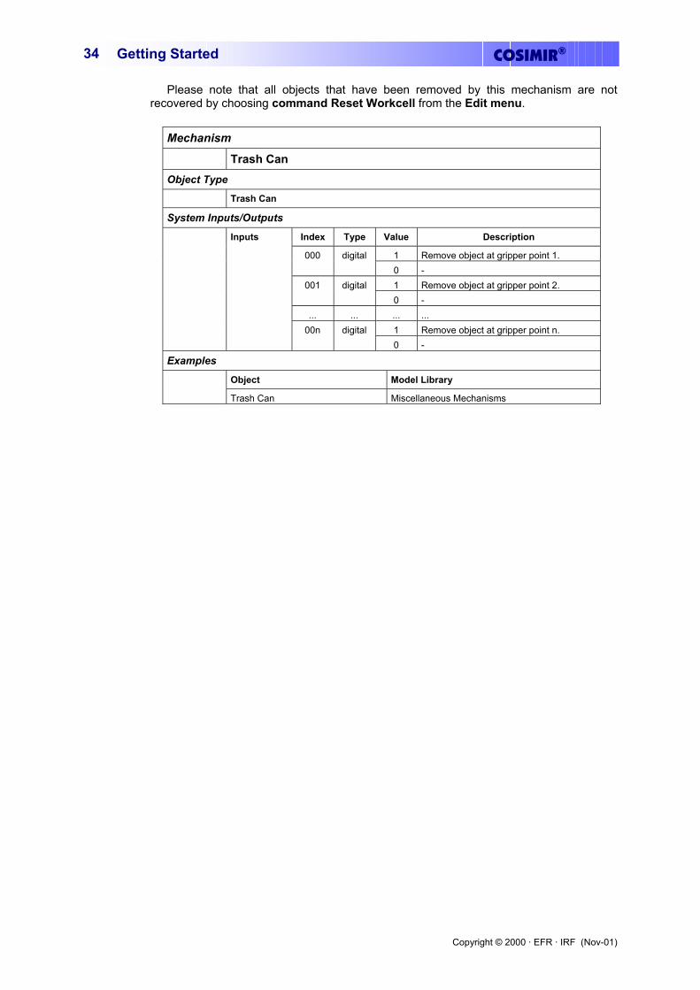
6.11 Trash Can The trash can is the counterpart of the replicator. Use the mechanism trash can to
remove objects at runtime. Each system input of the trash can object is associated to a gripper point. If system input 1 is set to high and there is an object with a free grip point inside the grip range of grip point 1 of the trash can object, the object is removed.
Copyright © 2000 · EFR · IRF (Nov-01)
COSIMIR®Getting Started 34
Please note that all objects that have been removed by this mechanism are not recovered by choosing command Reset Workcell from the Edit menu.
Mechanism Trash Can Object Type Trash Can
System Inputs/Outputs Index Type Value Description
1 Remove object at gripper point 1. 000 digital 0 - 1 Remove object at gripper point 2. 001 digital 0 -
... ... ... ... 1 Remove object at gripper point n.
Inputs
00n digital 0 -
Examples
Object Model Library
Trash Can Miscellaneous Mechanisms
Copyright © 2000 · EFR · IRF (Nov-01)
COSIMIR® Getting Started 35
7. Extensions
The basic functionality of COSIMIR® can be extended. In this chapter the most important extensions are described.
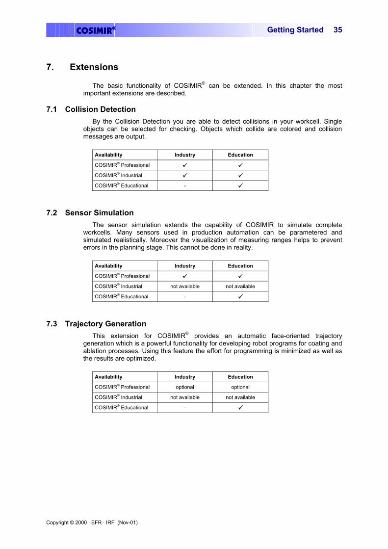
7.1 Collision Detection By the Collision Detection you are able to detect collisions in your workcell. Single
objects can be selected for checking. Objects which collide are colored and collision messages are output.
Availability Industry Education
COSIMIR® Professional COSIMIR® Industrial COSIMIR® Educational -
7.2 Sensor Simulation The sensor simulation extends the capability of COSIMIR to simulate complete
workcells. Many sensors used in production automation can be parametered and simulated realistically. Moreover the visualization of measuring ranges helps to prevent errors in the planning stage. This cannot be done in reality.
Availability Industry Education
COSIMIR® Professional COSIMIR® Industrial not available not available
COSIMIR® Educational -
7.3 Trajectory Generation This extension for COSIMIR® provides an automatic face-oriented trajectory
generation which is a powerful functionality for developing robot programs for coating and ablation processes. Using this feature the effort for programming is minimized as well as the results are optimized.
Availability Industry Education
COSIMIR® Professional optional optional
COSIMIR® Industrial not available not available
COSIMIR® Educational -
Copyright © 2000 · EFR · IRF (Nov-01)
COSIMIR®Getting Started 36
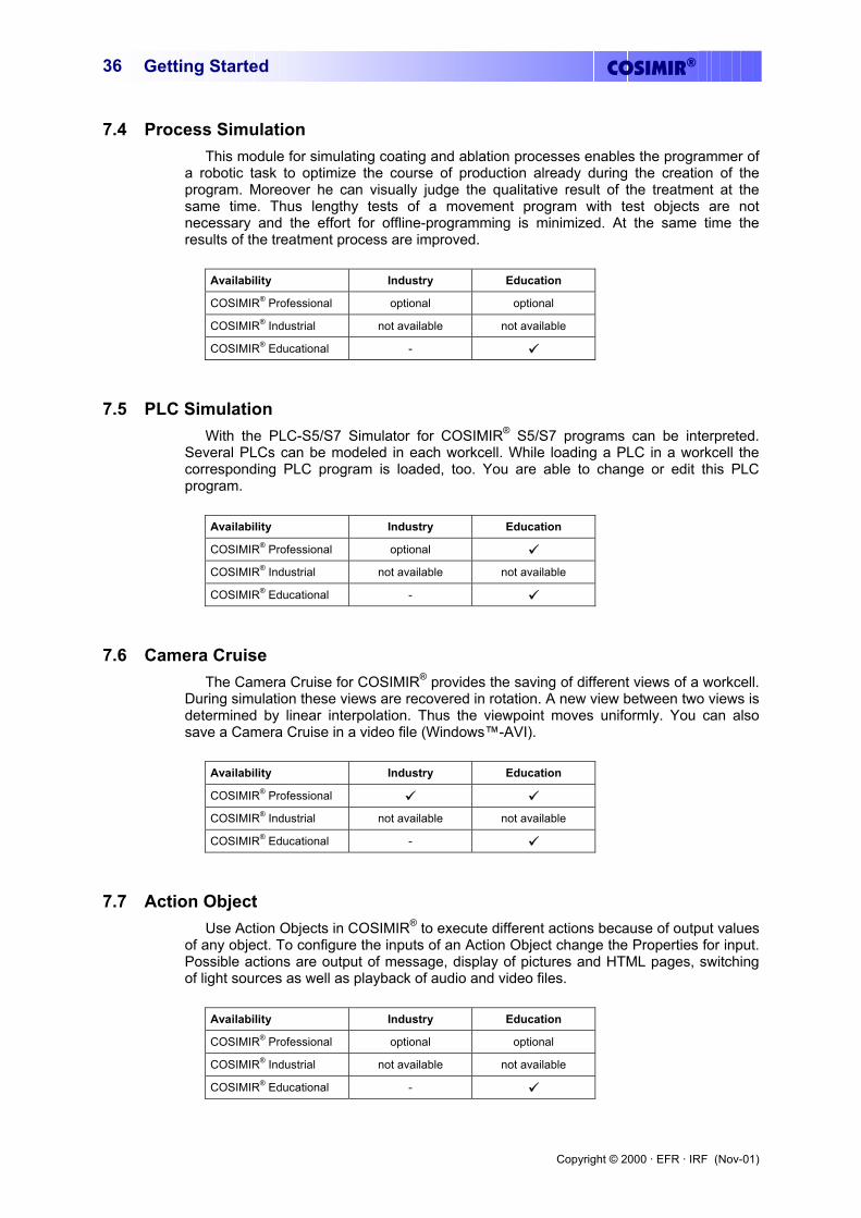
7.4 Process Simulation This module for simulating coating and ablation processes enables the programmer of
a robotic task to optimize the course of production already during the creation of the program. Moreover he can visually judge the qualitative result of the treatment at the same time. Thus lengthy tests of a movement program with test objects are not necessary and the effort for offline-programming is minimized. At the same time the results of the treatment process are improved.
Availability Industry Education
COSIMIR® Professional optional optional
COSIMIR® Industrial not available not available
COSIMIR® Educational -
7.5 PLC Simulation With the PLC-S5/S7 Simulator for COSIMIR® S5/S7 programs can be interpreted.
Several PLCs can be modeled in each workcell. While loading a PLC in a workcell the corresponding PLC program is loaded, too. You are able to change or edit this PLC program.
Availability Industry Education
COSIMIR® Professional optional COSIMIR® Industrial not available not available
COSIMIR® Educational -
7.6 Camera Cruise The Camera Cruise for COSIMIR® provides the saving of different views of a workcell.
During simulation these views are recovered in rotation. A new view between two views is determined by linear interpolation. Thus the viewpoint moves uniformly. You can also save a Camera Cruise in a video file (Windows™-AVI).
Availability Industry Education
COSIMIR® Professional COSIMIR® Industrial not available not available
COSIMIR® Educational -
7.7 Action Object Use Action Objects in COSIMIR® to execute different actions because of output values
of any object. To configure the inputs of an Action Object change the Properties for input. Possible actions are output of message, display of pictures and HTML pages, switching of light sources as well as playback of audio and video files.
Availability Industry Education
COSIMIR® Professional optional optional
COSIMIR® Industrial not available not available
COSIMIR® Educational -

Copyright © 2000 · EFR · IRF (Nov-01)
COSIMIR® Getting Started 37
8. Appendix
8.1 Keyboard Usage
Key Shortcut SHIFT+F5 Cascade windows.
SHIFT+F4 Tile windows.
ALT+F4 Quit the program.
F7 Displays the joint values of the robot.
SHIFT+F7 Displays the tool coordinates in world coordinates.
F8 Displays the window Teach-In
F9 Displays the input signals.
SHIFT+F9 Displays the output signals.
CTRL+N Command File New
CTRL+O Command File Open
SHIFT+F12 Command File Save
F12 Command File Save as
CTRL+P Command File Print
CTRL+A Command Edit Select all
ALT+EINGABE Command Edit Properties
CTRL+X Command Edit Cut: Cuts the selected text out of the window and puts it into the clipboard.
CTRL+C Command Edit Copy: Copies the active window or selected text into the clipboard.
CTRL+V Command Edit Paste: Pastes the contents of the clipboard into the active window.
CTRL+K Opens the dialog box for configuration of coordinate systems. Select here which coordinate systems shall be displayed.
CTRL+E Toggles between Edit Mode and Simulation Mode
CTRL+T Opens or closes the Model Explorer.
The following shortcuts depend on the type of the activated window. These shortcuts are available in case of an activated workcell window:
Key Shortcut CTRL+L Opens the dialog box for setting the point of view to the workcell.
“+”-KEY Activates the command zoom-in. It magnifies the view of the workcell.
“-“-KEY Activates the command zoom-out. It reduces the view of the workcell.
O Activates the command default settings.
V Activates the command front view.
U Activates the command rear view.
A Activates the command top view.
L Activates the command left side view.
R Activates the command right side view.
F Activates the command full format.
Copyright © 2000 · EFR · IRF (Nov-01)
COSIMIR®Getting Started 38
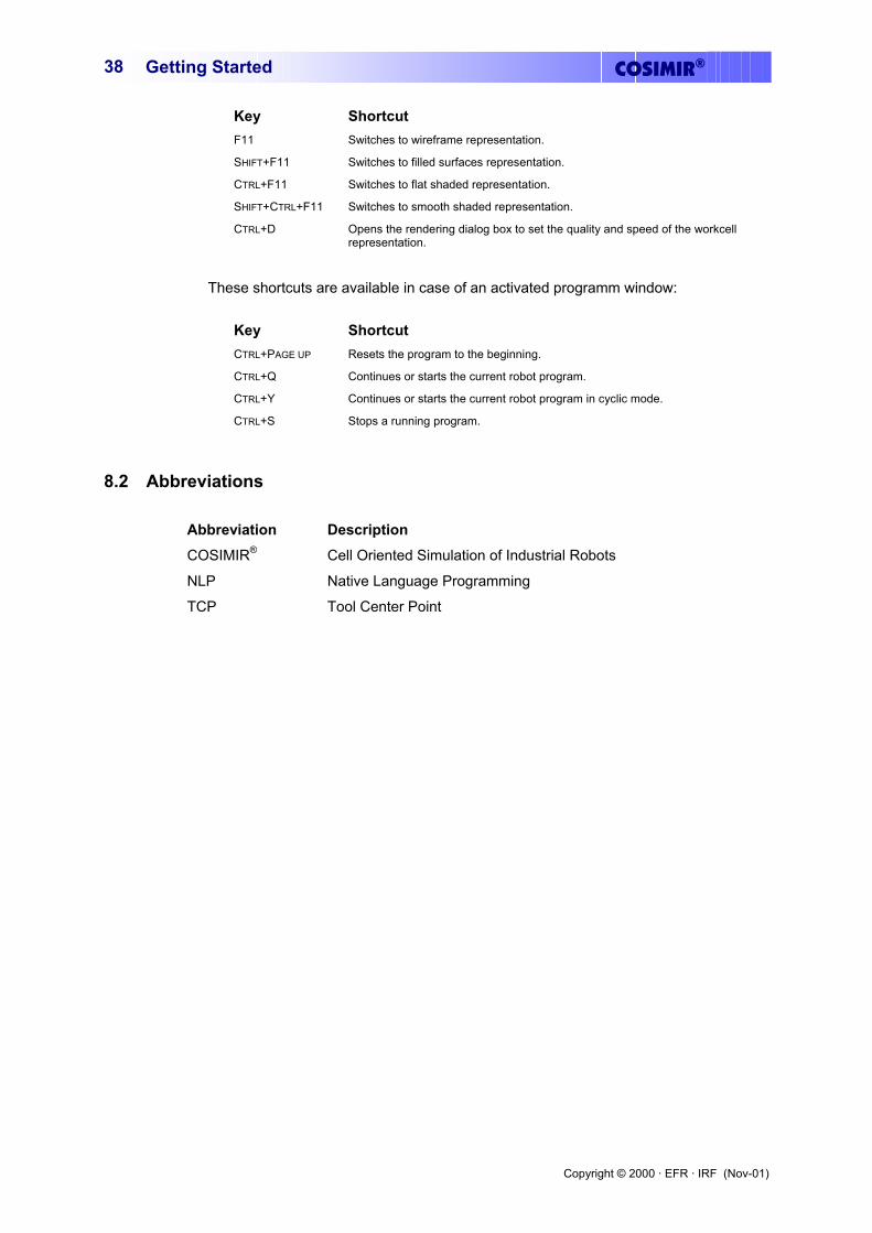
Key Shortcut F11 Switches to wireframe representation.
SHIFT+F11 Switches to filled surfaces representation.
CTRL+F11 Switches to flat shaded representation.
SHIFT+CTRL+F11 Switches to smooth shaded representation.
CTRL+D Opens the rendering dialog box to set the quality and speed of the workcell representation.
These shortcuts are available in case of an activated programm window:
Key Shortcut CTRL+PAGE UP Resets the program to the beginning.
CTRL+Q Continues or starts the current robot program.
CTRL+Y Continues or starts the current robot program in cyclic mode.
CTRL+S Stops a running program.
8.2 Abbreviations
Abbreviation Description COSIMIR® Cell Oriented Simulation of Industrial Robots
NLP Native Language Programming
TCP Tool Center Point
Copyright © 2000 · EFR · IRF (Nov-01)
COSIMIR® Getting Started 39
8.3 Index
A
Abbreviations....................................................... 38 Action Object ....................................................... 36
C
Camera Cruise...................................................... 36 Clipboard ............................................................. 37 Collision Detection .............................................. 35 Controller Selection ............................................. 14 Conveyor Belt ...................................................... 29 Coordinate Systems.............................................. 37
E
Edit Mode............................................................. 37 Extensions ............................................................ 35
G
Grip Points ........................................................... 17 Gripper ................................................................. 29 Gripper Points ...................................................... 17
H
Hulls..................................................................... 17
I
Import..................................................................... 5 Inputs/Outputs...................................................... 14
J
Joint Coordinates ................................................. 13
K
Keyboard Usage................................................... 37
M
Mechanisms ......................................................... 29 Model Explorer .................................................... 18 Model Hierarchy .................................................. 17 Model Libraries.................................................... 17 Modeling.............................................................. 17 Modeling Extensions.............................................. 5
N
NLP...................................................................... 38
O
Objects ................................................................. 17 Operating.............................................................. 13
Operating Systems ................................................. 5
P
Parts Feeder.......................................................... 32 PLC Simulation.................................................... 36 Position List ......................................................... 15 Process Simulation............................................... 36 Programming ....................................................... 23 Proximity Sensor.................................................. 33 Push Cylinder....................................................... 30
R
Replicator............................................................. 33 Representation
Filled Surfaces ................................................. 38 Flat Shaded ...................................................... 38 Smooth Shaded ................................................ 38 Wireframe ........................................................ 38
Robot Program..................................................... 15 Rotary Drive ........................................................ 30
S
Sections................................................................ 17 Sensor Simulation ................................................ 35 Simulation............................................................ 27 Simulation Mode.................................................. 37 Simulation System ................................................. 5
T
TCP...................................................................... 38 Teach-In ............................................................... 14 Text Formats .......................................................... 5 Trajectory Generation .......................................... 35 Trash Can............................................................. 33 Turning Mover..................................................... 32 Turntable.............................................................. 31 Two Way Push Cylinder ...................................... 31
U
User Input/Output ................................................ 15 User Interface....................................................... 13
W
Window Messages ............................................... 25 Window Types..................................................... 13 Workcell Window................................................ 13 World Coordinates ............................................... 14


EF-Robotertechnik GmbH D-58239 Schwerte, GERMANY Phone: +49 2304 44447 Fax: +49 2304 46655 eMail: [email protected] Internet: www.efr-gmbh.de
Institute of Robotics Research Director: Prof. Dr.-Ing. E. Freund in cooperation with partners
ww
w.c
osi
mir
.co
m
eMail: [email protected]: www.irf.de
Otto-Hahn-Str. 8 D-44227 Dortmund, GERMANY
Phone: +49 231 755-4650/1/2 Fax: +49 231 755-4653
Festo Didactic GmbH & Co. D-73770 Denkendorf, GERMANY Phone: +49 711 3467-0 Fax: +49 711 3467-355 eMail: [email protected] Internet: www.festo.com/didactic/
Mitsubishi Electric Europe B. V. D-40880 Ratingen, GERMANY Phone: +49 2102 486-483 Fax: +49 2102 486-717 eMail: [email protected] Internet: www.mitsubishi-automation.de