Embed Size (px)
Citation preview

Special issue of Terrestrial, Atmospheric and Oceanic Science, 11(1), 21-52, March 2000.
1
COSMIC System DescriptionC. Rocken, Y.-H. Kuo, W. Schreiner, D. Hunt, S. Sokolovskiy
University Corporation for Atmospheric ResearchCOSMIC Project Office
Chris McCormickBroad Reach Inc.
AbstractThe Constellation Observing System for Meteorology Ionosphere and Climate (COSMIC) is a satellite
mission for the Earth sciences that will make use of recent developments in remote sensing,communications technology, and computing to solve some of the most important geo-scientific issuestoday. COSMIC plans to launch eight Low Earth Orbit (LEO) satellites in 2003. Each of these spacecraftwill carry three science payloads for weather and space weather research and prediction, climatemonitoring, and geodesy: 1) GPS occultation receiver, 2) Tiny Ionospheric Photometer (TIP), and 3)Triband Beacon transmitters (TBB). Each of the LEOs will track the GPS satellites as they are occultedbehind the Earth limb to retrieve up to 500 daily profiles of key ionospheric and atmospheric properties.Every day the constellation will provide globally about 4000 GPS soundings. TIP will measure electrondensities at the peak of the F2 layer along the satellite track. TBB transmissions will be received on theground for high-resolution tomographic reconstruction of the ionospheric electron density. COSMICcontinuos precise tracking of all GPS satellites in view, also promise to benefit geodetic studies. TheCOSMIC system includes the LEO satellites, ground data reception and spacecraft control stations, dataanalysis centers and the data communications networks. This paper gives a COSMIC science overview anddescribes the COSMIC system.
1. COSMIC Science and Products
1.1. Science Mission for COSMIC - Overview
Data from the Constellation Observing System for Meteorology Ionosphere and Climate (COSMIC)will shed a new and revealing light on a wide variety of natural phenomena that are of considerableimportance to the scientific community and to society as a whole. COSMIC is an interdisciplinary satellitemission that will address some of the most intriguing questions in the Earth sciences today.
In meteorology the COSMIC data set will allow us to investigate the global water vapor distributionand map the atmospheric flow of water vapor that is so crucial for weather analysis and prediction (Crook,1996, Anthes et al., 1997, Kuo et al., 1997). The high vertical resolution of the data set (Karayel andHinson, 1997, Gurbunov and Gurvitch, 1998) will provide accurate geopotential heights (Leroy, 1997),enable the detection of gravity waves from the upper troposphere to the stratosphere (Tsuda et al., 2000),reveal the height and shape of the tropopause globally with unprecedented accuracy, support theinvestigation of fronts and other baroclinic structures (Kuo et al. 1998), and improve our understanding oftropopause-stratosphere exchange processes. One key goal of COSMIC is to demonstrate improvements inthe performance of numerical weather models, especially in polar and oceanic regions.
For climate studies COSMIC will monitor Earth’s atmosphere with unprecedented long-term stability,resolution, coverage, and accuracy. It will thus collect a data set for the detection of climate variability andchange, the separation of natural and anthropogenic causes, and the testing of climate models (Yuan et al.,1993, North and Stevens, 1998, Stevens, 1998, Leroy, 1998). Upper-tropospheric refractivity data fromCOSMIC may shed new light on the recent controversy over the role that tropical convection plays inclimate feedback (Lindzen, 1990, Rind, 1998). COSMIC will enhance studies of changes associated withEl Nino events especially in remote oceanic regions, and it will enable scientists to monitor the response of

Special issue of Terrestrial, Atmospheric and Oceanic Science, 11(1), 21-52, March 2000.
2
the global atmosphere to regional events such as large volcanic eruptions, the Kuwait oil fires, or the largeIndonesian forest fires.
In the ionosphere COSMIC data will accelerate the development of physical models for space weatherprediction by providing dense, accurate, and global electron density measurements for model testing andinitialization (Hajj et al., 1994, Howe et al., 1998, Rius et al., 1997, 1998). The large volume of high qualityionospheric observations from COSMIC will significantly advance space weather research. Scientists willbe able to observe the response of the global ionosphere to the impact of a solar storm as its effectspropagate around the globe. New revelations from this data set will improve physical ionospheric modelsand thus contribute to the development of predictive skills for space weather.
Each satellite in the COSMIC constellation will be tracked with high accuracy using GPS. This orbittrajectory information shall be used to improve our knowledge of the Earth’s gravity field and geoid(Lemoine, 1998). Improvements in the gravity field have far reaching impact on the Earth Sciences and onoperational civilian and military applications. Changes in the gravity field reveal changes in the Earth'smass distribution due to core-mantel, tectonic, hydrological, glacial, oceanographic, or atmospheric effects.Better gravity fields also lead to more accurate satellite orbit estimation and can thus improve GPSsurveying and benefit geodetic science.
1.2. COSMIC Data Products
Atmospheric and ionospheric profiles are derived by the radio occultation technique. As a signaltravels through the atmosphere it is retarded and bent. This results in a phase and Doppler shift, which canbe measured very accurately by the GPS receiver aboard the low-Earth orbiting COSMIC satellites. Sincethe transmitter and receiver positions and velocities are accurately know from precise orbit determination(POD), signal bending, α, as a function of impact parameter, a, (see Figure 1) can be computed from theDoppler shift observed at the Low Earth Orbiter (LEO). From the basic bending angle vs. impact parameterdata, vertical profiles of refractivity as a function of tangent point radius, r, can be derived. Further analysisconverts refractivity to electron density in the ionosphere (Hajj and Romans, 1998, Schreiner et al., 1999).In the neutral atmosphere (stratosphere and troposphere), the bending angle-derived refractivity profiles,are primarily a function of temperature, pressure, and water vapor (i.e. Gurvitch and Sokolovskiy 1983,Melbourne et al., 1994, Feng et al., 1995, Ware et al., 1996, Hoeg et al., 1996, Hocke, 1997, Kursinski etal., 1996, 1997, Rocken et al. 1997). Effects due to hydrometeors and other particulates are generallyignored (Solheim et al., 1999).
α GPS
COSMICLEO
ar
a
Earth
Tangent Point
Figure 1 Occultation observation geometry
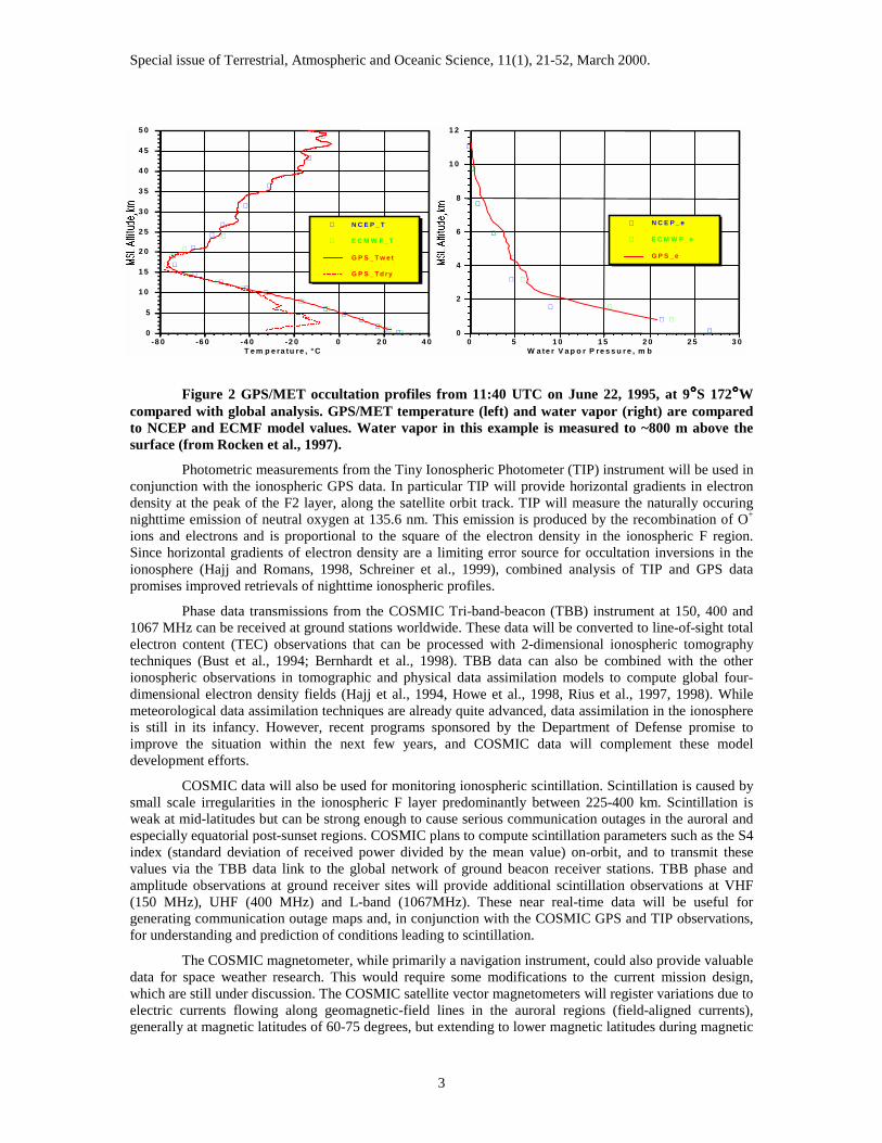
Where water vapor is negligible, such as in the stratosphere and upper troposphere, pressure andtemperature may be obtained directly from the refractivity. Where water vapor is present in significantamounts, it is impossible, without additional independent data, to separate out the effects of temperatureand water vapor. However, if a reasonably accurate independent estimate of temperature is available (forexample, from a global analysis or a 12-hour forecast), accurate profiles of water vapor and total pressurecan be obtained (Figure 2).
Eyre (1994) stated that the most powerful use of COSMIC neutral atmosphere data is toassimilate the refractivity or bending angle profiles directly into numerical models. In this way a minimumnumber of assumptions are made. Numerical experiments have shown that assimilation of refractivity (Zouet al., 1995) and bending angles directly into numerical models causes the model’s temperature, watervapor, and wind fields to adjust toward actual atmospheric values (Kuo et al., 1997, Zou et al., 1999, 2000).
Special issue of Terrestrial, Atmospheric and Oceanic Science, 11(1), 21-52, March 2000.
3
Figure 2 GPS/MET occultation profiles from 11:40 UTC on June 22, 1995, at 9°°°°S 172°°°°Wcompared with global analysis. GPS/MET temperature (left) and water vapor (right) are comparedto NCEP and ECMF model values. Water vapor in this example is measured to ~800 m above thesurface (from Rocken et al., 1997).
Photometric measurements from the Tiny Ionospheric Photometer (TIP) instrument will be used inconjunction with the ionospheric GPS data. In particular TIP will provide horizontal gradients in electrondensity at the peak of the F2 layer, along the satellite orbit track. TIP will measure the naturally occuringnighttime emission of neutral oxygen at 135.6 nm. This emission is produced by the recombination of O+
ions and electrons and is proportional to the square of the electron density in the ionospheric F region.Since horizontal gradients of electron density are a limiting error source for occultation inversions in theionosphere (Hajj and Romans, 1998, Schreiner et al., 1999), combined analysis of TIP and GPS datapromises improved retrievals of nighttime ionospheric profiles.
Phase data transmissions from the COSMIC Tri-band-beacon (TBB) instrument at 150, 400 and1067 MHz can be received at ground stations worldwide. These data will be converted to line-of-sight totalelectron content (TEC) observations that can be processed with 2-dimensional ionospheric tomographytechniques (Bust et al., 1994; Bernhardt et al., 1998). TBB data can also be combined with the otherionospheric observations in tomographic and physical data assimilation models to compute global four-dimensional electron density fields (Hajj et al., 1994, Howe et al., 1998, Rius et al., 1997, 1998). Whilemeteorological data assimilation techniques are already quite advanced, data assimilation in the ionosphereis still in its infancy. However, recent programs sponsored by the Department of Defense promise toimprove the situation within the next few years, and COSMIC data will complement these modeldevelopment efforts.
COSMIC data will also be used for monitoring ionospheric scintillation. Scintillation is caused bysmall scale irregularities in the ionospheric F layer predominantly between 225-400 km. Scintillation isweak at mid-latitudes but can be strong enough to cause serious communication outages in the auroral andespecially equatorial post-sunset regions. COSMIC plans to compute scintillation parameters such as the S4index (standard deviation of received power divided by the mean value) on-orbit, and to transmit thesevalues via the TBB data link to the global network of ground beacon receiver stations. TBB phase andamplitude observations at ground receiver sites will provide additional scintillation observations at VHF(150 MHz), UHF (400 MHz) and L-band (1067MHz). These near real-time data will be useful forgenerating communication outage maps and, in conjunction with the COSMIC GPS and TIP observations,for understanding and prediction of conditions leading to scintillation.
The COSMIC magnetometer, while primarily a navigation instrument, could also provide valuabledata for space weather research. This would require some modifications to the current mission design,which are still under discussion. The COSMIC satellite vector magnetometers will register variations due toelectric currents flowing along geomagnetic-field lines in the auroral regions (field-aligned currents),generally at magnetic latitudes of 60-75 degrees, but extending to lower magnetic latitudes during magnetic
∇∇∇∇
∇∇
∇∇
∇∇
∇∇∇
∇
∇∇
∇
∇
∇
∇
⊗⊗⊗⊗
⊗⊗
⊗⊗
⊗⊗
⊗⊗
⊗
⊗
0
5
1 0
1 5
2 0
2 5
3 0
3 5
4 0
4 5
5 0
-8 0 -6 0 -4 0 -2 0 0 2 0 4 0T e m p e ra tu re , ° C
∇ N C E P _ T
⊗ E C M W F _ T
G P S _ T w e t
G P S _ T d ry
∇
∇
∇
∇
∇
∇
∇
∇
∇
⊗
⊗
⊗
⊗
⊗
⊗
⊗
⊗
0
2
4
6
8
1 0
1 2
0 5 1 0 1 5 2 0 2 5 3 0W a te r V a p o r P re s s u r e , m b
∇ N C E P _ e
⊗ E C M W F _ e
G P S _ e

Special issue of Terrestrial, Atmospheric and Oceanic Science, 11(1), 21-52, March 2000.
4
storms (Richmond and Kamide, 1998). Horizontal deflections are of the order of hundreds of nanotesla(nT), often exceeding 1000 nT during disturbed periods. In addition to the use of the vector deflections,additional information can be obtained simply from looking at the power of the magnetic fluctuations atroughly 1-10 Hz (Brian Anderson, private communication, 1999). Such fluctuations correlate well withpassage through field-aligned currents, and can thus be used to determine the size of the auroral oval, animportant parameter for space weather purposes. COSMIC satellites at 72 degree inclination will passthrough the auroral ovals of both hemispheres on most orbits.
In addition to the occultation GPS data, COSMIC GPS receivers will collect 0.1 Hz dualfrequency phase data from all GPS satellites in view. Gravity field and GPS orbit improvement will beachieved by ingesting the COSMIC GPS phase observations and other relevant information about thesatellite (i.e. mass distribution, attitude) into well established geodetic and orbit parameter estimationmodels. This will have a direct impact on geodetic science by improving gravity field models, the referenceframe, and GPS satellite orbits, and an indirect impact through improved global fields of pressure,temperature, moisture, and electron density. Accurate long term monitoring of the gravity field willimprove the spatial and temporal understanding of a variety of mass motion processes within the solidEarth, atmosphere, ocean, and cryosphere. The current state-of-the-art gravity model is the Earth GravityModel EGM-96 (Lemoine et al., 1998). For COSMIC data to provide significant improvement overEGM96, it is necessary for pairs of satellites to fly in tandem (with 300-1000 km separation) at the lowestaltitude possible. E. Pavlis (1998, unpublished results) computed a gravity field with 32 days of simulatedCOSMIC data. His results show an expected order of magnitude improvement in coefficient uncertaintyover EGM96, out to degree and order 20-40 (spatial resolution of 1000-500 km). Geoid errors also showorder of magnitude improvement over EGM96 out to at least degree and order 40. Such improvements tothe static gravity field and geoid will benefit many past and future geodetic satellite missions.Improvements to estimates of temporal variations of the gravity field coefficients will not be obtainablewith COSMIC because of the necessity to stay at low altitudes for a long time. The COSMIC engineeringteams at UCAR and at Taiwan's National Space Program Office (NSPO) are designing the mission tomaximize the value of gravity observations. This requires a trade-off between the scientific demand for loworbits for as long as possible and the engineering requirement to minimize the required on-board propellant.
In summary, COSMIC aims to satisfy the following high-level science requirements.
Table 1 COSMIC Science RequirementsData Parameter Science Requirement CommentVertical GPS occ. resolution 0.3 - 1.5 km 0.3 km near surface, 1.5 km at 45 kmHorizontal GPS occ. resolution 300-600 km Smaller for fronts with large slopeBending angle profile 1.5 10-6 rad Limited mainly by residual ionospheric error
and data noiseRefractivity profile < 1 % As good as 0.2% between 10-30 kmTemperature profile 1 deg C In 0-40 km height range, assuming dry airWater vapor profile < 1-10% Between 0-5 km, assuming model temp. error
of 1-2 deg; errors between 5-10 km largerGeopotential height vs. pressure 10-20 m Between 0-30 km (worse at solar maximum)Electron density profile < 1-20% Profile quality near the F2 peak- can be worse
elsewhere; Limited by horizontal gradientsGPS TEC 0.001 TECU Relative TEC (absolute ~ 3-5 TECU)TBB TEC 0.003 TECU Relative TEC (absolute ~ 1-3 TECU)TIP peak foF2 density, NmF2 < 1-10% Performs better at high electron densities
Works only on the night side of the globeMagnetometer measurement * 10 nano-tesla (nt) Precision @ 1Hz rate, 500 nt accuracy
(* feasibility still under consideration)Scintillation GPS n/a 100 Hz SNR data used to determine S4Scintillation TBB n/a 50-1000 Hz SNR dataLEO Position ~ 10 cm 3-D rms position error (not critical)LEO velocity < 0.1 mm/s Relative velocity error for paired satellites
Special issue of Terrestrial, Atmospheric and Oceanic Science, 11(1), 21-52, March 2000.
5
will be smaller due to common errors
Many of the science requirements in Table 1 are based on experience from GPS/MET (i.e. Rockenet al., 1997) and theoretical error studies (i.e. Kursinski et al., 1997). The ionospheric profiling errors withthe wide range of 1-20% are based on recent NmF2 comparisons from GPS/MET (i.e. Schreiner et al.1999) and do not apply in the E-layer where the agreement is often worse. The accuracy of these results islimited by the assumption of horizontal ionospheric homogeneity. Combined analysis of TIP, TBB andGPS data promises to improve the quality of retrieved ionospheric profiles. At this point funding for theconversion of the magnetometer from a navigation to a science instrument has not been approved.
2. COSMIC System
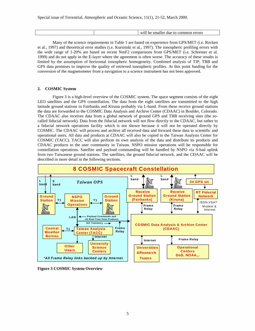
Figure 3 is a high-level overview of the COSMIC system. The space segment consists of the eightLEO satellites and the GPS constellation. The data from the eight satellites are transmitted to the highlatitude ground stations in Fairbanks and Kiruna probably via L-band. From these receive ground stationsthe data are forwarded to the COSMIC Data Analysis and Archive Center (CDAAC) in Boulder, Colorado.The CDAAC also receives data from a global network of ground GPS and TBB receiving sites (the so-called fiducial network). Data from the fiducial network will not flow directly to the CDAAC, but rather toa fiducial network operations facility which is not shown because it will not be operated directly byCOSMIC. The CDAAC will process and archive all received data and forward these data to scientific andoperational users. All data and products at CDAAC will also be copied to the Taiwan Analysis Center forCOSMIC (TACC). TACC will also perform its own analysis of the data and distribute its products andCDAAC products to the user community in Taiwan. NSPO mission operations will be responsible forconstellation operations. Satellite and payload commanding will be handled by NSPO via S-bad uplinkfrom two Taiwanese ground stations. The satellites, the ground fiducial network, and the CDAAC will bedescribed in more detail in the following sections.
ISDN,VSATModem & Internet
8 COSMIC Spacecraft Constellation
CentralWeatherBureau
GroundStation
NSPOMission
Operations
UniversityScienceCenters
ReceiveGround Station
(Fairbanks)
ReceiveGround Station
(Kiruna)
COSMIC Data Analysis & Archive Center(CDAAC)
Universities&Research
ESEARCTeam s
OperationalCenters
DoD, NOAA,..
RT FiducialNetwork
*All Frame Relay links backed up by Internet.
L band
Sband
T1
Internet
Lband
Lband
Internet
Payload Commands andAll Real-Time Data ProductsS/C Telemetry
Taiwan OPS
T1
OtherUsers
Fram eRelay
Fram e R elay
24 GPS s/c
Taiwan AnalysisCenter (TACC)
T1
LAN
Fram eRelay
Fram eRelay
GroundStation
Figure 3 COSMIC System Overview

Special issue of Terrestrial, Atmospheric and Oceanic Science, 11(1), 21-52, March 2000.
6
2.1. The COSMIC Satellites
During the initial COSMIC study phase a preliminary design of the COSMIC spacecraft wascompleted. The satellite manufacturer has yet to be selected and the preliminary design will likely bechanged considerably. The total spacecraft mass is expected to be ~40 kg (including propellant). Thespacecraft shall be 3-axis stabilized and shall feature a monopropellant (hydrazine) propulsion system, fororbit insertion, maintenance and de-orbiting. The overall propellant mass is expected to be about 8 kg,sufficient for a total velocity change of 450 m/s. Solar panels shall be sized to provide 55 W of orbitaverage power to the spacecraft. The COSMIC spacecraft shall be designed to launch eight spacecraft on asingle launch vehicle.
The Attitude Control System (ACS) is planned to be a pitch-momentum biased system. Thevehicle’s attitude is primarily nadir with fixed forward and aft facing GPS antennas. There are threeorthogonal torque rods to control the roll and yaw axis, as well as control and dissipate momentum built upin the pitch oriented reaction wheel. There is one earth sensor to achieve ~0.1 degree pitch knowledgerequired for the TIP, and a magnetometer to achieve three axis determination for the mission to ~1 degree.The spacecraft also includes a solid state Inertial Reference Unit (IRU) to null out rates during propulsionorbit raise and orbit maintenance maneuvers.
The power subsystem is based on two Gallium-Arsenide based solar arrays in a fixed deployedconfiguration. The solar array will not be articulated for cost, complexity, and aerodynamic dragconsiderations. The batteries are Li-Ion based 14.4 volt, 15 Amp-Hr, aerospace cells. Power distributionand battery charging are accomplished with solid state, analog control looped based, switches (HexFETs),and monitoring systems to ensure proper power utilization and safe hold modes. The power distributionsystem also contains the propulsion valve drivers in order to operate the propulsion nozzles in a pulse widthmodulated method.
Propulsion is a blowdown hydrazine system with a cluster of four axial canted thrusters. Thesethrusters are operated in a pulse-width-modulated method in order to achieve three-axis control, and therequired velocity changes (delta-V) for the orbit raise and maintenance maneuvers. Fuel mass fraction forthis mission is approximately 20% or 8 kg of hydrazine.
The flight computer and solid state recorder shall be based on commercially produced, radiationtested or radiation-hardened low power parts. The flight computer contains a PowerPC microprocessor,EEPROM, PCI communications bus and system memory. The solid state recorder, on the PCI bus, containsapproximately 64Mbytes of store and forward memory for the instruments. The communications interfacecard, also on the PCI bus, contains all the communications protocols and command decoding to orchestratethe physical layer communications and low level relay commands.

Special issue of Terrestrial, Atmospheric and Oceanic Science, 11(1), 21-52, March 2000.
7
Nadir RX PatchNadir TX
1λ Quadrafilar
Propulsion Valve &Nozzle AssembliesUmbilical/
SeparationInterface
RS-485data bus
5MHz (optional)
GPS hi-gainAntenna +V
Limb viewing
GPS PatchAntenna+V POD
GPS hi-gainAntenna -V
Limb viewing
GPS PatchAntenna-V POD
Pitch EarthSensor
3 axis Magnetometer
ReactionWheel
IRU - 3 axis
3 orthogonalTorque Rods
L-Band, Agile5W Transmitter
S-Band, AgileReceiver
L-band Beacon Antenna
Tri-Band Beacon TransmitterVHF Antenna
UHF Antenna
Flight Computer/Solid State Memory
Tiny IonospherePhotometer
Power Distribution Unit/Propulsion Valve Driver/
Battery Charge Regulator/Low level Comms & Phoenix Logic
Li-IonLi-IonLi-IonLi-Ion
4 cell Li-IonBased AerospaceCells (~14V bus)
Solar Panel /Deployed
Hydrazine Tank/Blow down/bladder type
Fill/Drain ValveLatch Valve
GPSInstrument
Figure 4 Preliminary design diagram of the main COSMIC satellite components.
The current design includes a TT&C system that consists of an S-Band FSK receiver designed fordata rates of 32kbps. The telemetry transmitter is a 2Mbps L-Band BPSK. The L-Band (1690 MHz to 1710MHz) is recommended for use because this part of the spectrum is already allocated for spacecraftmeteorology data downlink.
The software will incorporate a real-time operating system. Most software development will berequired for the attitude control modes (safe hold, propulsion maneuvers, nadir following, etc.), while asmaller portion is for the state-of-health, command, payload operations, data communications, and compactfile system orchestration. Additional capability must be developed for software uplink and reprogramming.
2.2. The COSMIC Orbit Constellation
Launch of eight COSMIC micro-satellites into LEO is planned for 2003. The desired orbits are 72degrees inclination and 800 km circular, with all spacecraft in their own orbital plane spaced approximately23 degrees apart in ascending node. Alternative orbits are also feasible and constellation design is still inprogress. The satellites will be pointed at nadir to ensure that the high-gain occultation antennas aredirected to within +/- 5 degrees of the Earth's limb. The satellites will maintain a fixed yaw orientation withthe high-gain antennas pointing in the velocity and anti-velocity directions. Attitude will be known to +/- 1degree at all times.
Depending on the final constellation a global snapshot can be achieved every 100 minutes. Thesystem will retrieve ~ 4,000 vertical profiles of the atmosphere each day. The result will be meteorologicaldata at heights from approximately 60 km to the surface and ionospheric data from approximately 90 to 800km.

Special issue of Terrestrial, Atmospheric and Oceanic Science, 11(1), 21-52, March 2000.
8
The COSMIC orbits will be chosen to balance mission science requirements with other missiondesign and cost priorities. The main scientific objective for the COSMIC mission is to provide the mostuseful atmospheric and ionospheric data products possible to the science community in near real time(within 2-3 hours of the observations). The primary science requirements recommended at the COSMICscience workshop in Taiwan (February, 1998) state a desire to maximize the number and the global refreshrate of the radio occultations produced by the constellation. Maximizing the number of occultations equatesto increasing the number of satellites in orbit. One LEO satellite can acquire approximately 500 rising andsetting occultations from the GPS constellation in one day. Maximizing the global refresh rate of theoccultations requires spreading out the satellite orbits equally in ascending node. This allows adequatesampling of the diurnal signal of Earth’s atmosphere and ionosphere every orbit. Additional sciencerequirements that helped establish guidelines for the COSMIC constellation include: orbit inclinations largeenough to give adequate polar coverage, and orbit altitudes that are above the majority of the ionosphereeven at solar maximum to improve ionospheric occultations and minimize drag.
The constellation design and analysis for this mission involves complex trade-offs between thescience requirements and many other issues. These issues are related to program cost, ground stationdownload coverage and data latency, mass to orbit launch capability, satellite deployment strategy, satellitefuel budget, and the design of the propulsion and attitude control systems. Because cost is the majorconstraint, the design emphasized the selection of a constellation that could simultaneously meet thescience objectives and that could also be deployed with a single launch vehicle. The least expensive way tophase multiple satellites in ascending node when using a single launcher is to precess the orbitsdifferentially over a period of time. Differential precession between orbits with different altitudes orinclinations occurs due to Earth oblateness ("J2") effects (i.e. Space Handbook, 1985). This requires a wellthought out constellation deployment strategy and additional fuel to change the altitudes and/or inclinationsof the orbits. After numerous trade studies, an initial design for the COSMIC constellation was completedand is summarized in Table 1.
Table 2: Summary of desired COSMIC satellite constellation parameters.
Design life 5 yearsNumber of spacecraft 8Number of planes 8Spacecraft mass 40 kilogramsSemi-major axis of parking orbit 400 kilometersSemi-major axis of operational orbit 800 kilometersOrbit Eccentricity 0, circularOrbit Inclination 72 degreesPlane separation in Ascending Node 22.5 degreesSpacecraft separation in Mean Anomaly 45.0 degreesDifferential precession drift time ~300 daysDelta-V fuel load (including reserve) ~455 meters/second
2.3. COSMIC Payloads
The primary COSMIC instrument will be an advanced GPS receiver developed by JPL. Thisreceiver is a heritage design of an earlier JPL-developed instrument that was flown aboard the MicroLab-1satellite during GPS/MET. The COSMIC GPS receivers will be able to track all GPS satellites in viewsimultaneously with two or more occulting satellites. It will operate fully autonomously, scheduling whento track which satellites and at what sampling rate based on its own known position and those of the GPSsatellites. The instrument will report high-rate (50, or even 100 Hz) dual frequency carrier phase change onthe occulting links with sub-mm precision for accurate high resolution profiling. Lower rate (0.1 Hz) phasemeasurements of all satellites in view will be collected for 5-10 cm-level orbit determination. The receiverhas to measure both GPS carrier frequencies to separate the frequency dependent (dispersive) ionosphericdelay from the non-dispersive refractive delay of the neutral atmosphere. In addition to accurate phasemeasurements, the GPS instrument can also record GPS signal amplitudes for on-orbit ionosphericscintillation monitoring and correction of signal diffraction effects in post-processing.

Special issue of Terrestrial, Atmospheric and Oceanic Science, 11(1), 21-52, March 2000.
9
Two additional instruments will orbit on COSMIC: the tiny ionospheric photometer (TIP) and atri-band beacon (TBB) transmitter, both built at the Naval Research Laboratory (NRL). The TIP is a nadirviewing 135.6 nm photometer, which measures naturally occurring extreme ultraviolet airglow. From TIPmeasurements the nighttime electron density at the peak of the F2 layer can be computed with high spatialresolution along the satellite tracks.
The TBB transmits three frequencies (150, 400 and 1067 MHz), which can be tracked by receiverson the ground or aboard other satellites. Measured phase differences between the different frequencies yieldtotal electron content along the transmitter to receiver paths. A COSMIC transmitter pass over a chain ofbeacon receivers on the ground will provide data for high-resolution two-dimensional tomographicmeasurements of electron density. Amplitude fluctuations of the TBB data will be used for scintillationmonitoring. The 1067 MHz TBB carrier frequency will be modulated to carry a low-rate data stream of on-orbit determined GPS scintillation parameters and important spacecraft health information.
TIP and TBB will complement the primary GPS occultation observations to provide much morecomplete three-dimensional fields of electron density in the ionosphere. The observational requirements fordata to be received at CDAAC during the COSMIC mission are summarized in Table 3. Theserequirements are driven by the science requirements from Table 1.
Table 3 COSMIC Observational Requirements
Measurement Parameter RequirementNumber of occultations ~ 4000 soundings/dayDistribution GlobalL1 / L2 phase measurement ~ 2 mm (10-sec, iono.-free data for POD)GPS phase sampling rate 0.1 - 50 Hz (the possible need for 100 Hz
sampling in the lower troposphere is stillunder investigation)
GPS vertical range neutral atmosphere surface - 60 km (50 Hz sampling)GPS vertical range ionosphere 90-800 km (10 Hz sampling)TBB phase measurement < 32 mm @ 150 MHz (ground receiver)TBB sampling rate > 50 Hz (ground receiver)TIP measurement < 10% (uncertainty in photon count)TIP footprint 125 x 25 km (at 400 km height of F2 layer)TIP resolution 0.1 -10 sec averagingMagnetometer 10 nT precision, 500 nT accuracy
(may not be included - not yet decided)
2.4. Ground Segments of COSMIC
The COSMIC system requires significant ground infrastructure. The key components of theCOSMIC system are shown in Figure 3. The main communication links are shown in Figure 5.
Each COSMIC satellite dumps its data to one of two high-latitude Earth stations once per orbitevery 100 minutes for immediate transmission to the near real-time CDAAC at UCAR. The CDAAC alsorequires data, from a global network of ~25 ground based receiver sites in near real time (within ~10 min.).These data include GPS observations, beacon transmissions from the COSMIC satellites received at thefiducial sites, and telemetry data sent via the beacon modulation to ground-based beacon receivers. TheGPS data are needed to compute precise COSMIC satellite orbits, and to eliminate errors due to GPStransmitter and receiver clock oscillator instabilities. The beacon data are used for ionospheric tomographyand scintillation monitoring in the vicinity of the beacon receiver site. The beacon telemetry data are usedprimarily for scintillation monitoring based on the GPS data received on orbit.

Special issue of Terrestrial, Atmospheric and Oceanic Science, 11(1), 21-52, March 2000.
10
Figure 5 Major COSMIC components, communications links data types and volumes. Datavolume for the fiducial sites was computed based on the assumption of 1-sec dual frequency phase,pseudorange and amplitude GPS data, collected from an average of 8 satellites. We assumedcompressed RINEX files and about 4 Mbytes of TBB data per fiducial site. For the LEO data weassumed 4000 50 Hz soundings/day with a data volume of 100 kbytes for one ionospheric andatmospheric sounding. This adds up to 400 Mbytes / day to which we added a 50% contingencybecause of uncertainties in the occultation data format and sampling rate.
The CDAAC analyzes all data and monitors payload performance. Data and higher level productswill be provided to researchers and operational centers worldwide. (See Table 4 for our definition of thedifferent product levels.) All data and products will be copied to the TACC in Taiwan. NSPO will beresponsible for mission operation and control including all satellite uploads from the two Taiwanese groundstations, and for the distribution of data and products to the Taiwanese operational and sciencecommunities. Next we describe the COSMIC fiducial network design, the Earth stations, and the CDAAC.
2.4.1. The Fiducial NetworkTo compute accurate radio occultation inversions it is necessary to remove the drifts of the GPS
transmitter and receiver clocks from the raw phase data. This can be done with common mode doubledifference viewing of the LEO and ground GPS data as illustrated in Figure 6.
GPS transmitter1 of 24
CDAAC
COSMICSatellite 1 of 8
Earth station1 of 2
L1 & L2
L1 & L2
L-banddata downlink
Beacon receiver
Tri-Band Beaconcarrier & data
Global (IGS)fiducial site1 of ~ 25
S-band uplink
~ 5 Mbytes / pass600 Mbytes / day total
16 Mbytes /site /day415 Mbytes / day total
Auxillary Met. Data,IGS orbits, etc.~ 15 Mbytes/day
User products &TACC connection
Payloadcommand

Special issue of Terrestrial, Atmospheric and Oceanic Science, 11(1), 21-52, March 2000.
11
Earth
LEO Satellite, B
Occulting GPSSatellite, #1
Non-Occulting ReferenceGPS Satellite, #2
GroundFiducial, A
1 Hz
1 Hz
50 Hz
50 Hz1AΦ
1BΦ
2AΦ
2BΦ
Figure 6 Shows the use of a fiducial site for forming a double difference. The fiducial sites will logGPS data (ΦΦΦΦ2
A and ΦΦΦΦ1A) at 1 second while the LEO will track the occulting and reference satellites at
50 Hz or maybe even at a higher rate (ΦΦΦΦ2B and ΦΦΦΦ1
B).
COSMIC and several other upcoming satellite missions (including Orsted, SUNSAT, SRTM,CHAMP, SAC-C, GRACE) plan to carry GPS receivers that will acquire radio occultation measurementsof the Earth’s atmosphere and ionosphere. During the GPS/MET mission a network of 6 sites (Potsdam,Germany: POTS, Fairbanks, Alaska: FAIR, Goldstone, California: GOLD, Kokee Park, Hawaii: KOKB,Tidbindilla, Australia: TID2, and McMurdo, Antartica : MCM4) was operated by JPL. This network mustbe expanded and improved to capture all future radio occultation data.
Simulation software was used to compute all double difference combinations between the GPSsatellites as viewed from the LEO satellites and ground sites. We found that all occultations can be doubledifferenced with a 13 station fiducial network when a 15-degree elevation cutoff mask is used. At least 20stations are required to capture all occultations with a 30 degree elevation mask.
It was also found that a LEO network of 8 evenly distributed satellites can provide completedouble difference coverage if the LEOs can track all GPS satellites in view that are above the F layer of theionosphere (~400 km). This approach would permit use of the double difference technique without therequirement for a 1-Hz ground fiducial network (simply replace ground fiducial site A in Figure 6 withanother COSMIC LEO satellite). For COSMIC this approach is considered experimental because it willincrease the time needed to analyze the occultations. With the ground fiducial approach only data from oneLEO and the ground network are required for profile analysis. If the ground fiducial data are available withno more than 10 minutes latency (as is planned for COSMIC) then the occultation data from each datadump at the Earth stations can be differenced with fiducial data within minutes of reception at the CDAAC.For processing with orbiting reference data, on the other hand one has to wait for one entire orbital periodafter each download (100 minutes) before the data can be differenced to eliminate clock errors.
2.4.1.1. Impact of high frequency ground fiducial multipathA potential problem with using ground based GPS data to remove unwanted clock signal from
occultation data is the presence of high frequency multipath. Evidence of site multipath can be seen in post-fit residual from GPS/MET fiducial phase data. Figure 7 shows evidence of site multipath at MCM4 andTID2 from the analysis of GPS/MET 1 Hz LC (linear combination – ionosphere free) phase data onconsecutive days in 1997: 97.034 and 97.035. Multipath is expected to repeat itself from one sidereal day tothe next. The correlation between the residuals on the consecutive days is apparent evidence of site

Special issue of Terrestrial, Atmospheric and Oceanic Science, 11(1), 21-52, March 2000.
12
multipath. Figure 7 shows temperature retrievals (using ground data from TID2, MCM4, and KOKB) for aGPS/MET occultation that occurred during the same time period (on 97.035) as shown in Figure 7. Thecurve for MCM4 deviates from the other curves by nearly 4 degrees C at 30 km. This is caused by themultipath of PRN 10 (elevation of 7 degrees), which has a velocity magnitude of nearly 1 cm/sec. Thecurves for TID2 and KOKB differ by ~0.5 degrees C at 30 km. This difference is caused by a more typicallevel of multipath (from PRN 05, elevation of 30 degrees) with a magnitude of near 1 mm/sec. The impactof high frequency multipath on occultation retrievals is significant and the subject of further study.
Figure 7 The left two panels show evidence of site multipath from the analysis of GPS/MET 1 Hz LCphase data on consecutive days. The top panel shows double difference phase residuals betweenMCM4 and TIDB over a 2 minute interval on 97.034 (YY.DOY, year and day of year). The bottompanel shows the residuals for the same sites on the following day (97.035), but shifted 4 minutesearlier. The high correlation of the residuals from 1 sidereal day to the next is evidence of multipath.The right top panel shows a plot of GPS/MET temperature inversions using 3 different fiducial sites:TID2, MCM4, and KOKB. The right bottom panel shows temperature differences.
2.4.1.2. High accuracy clocks for the COSMIC fiducial networkThis section discusses the required clock quality for receivers that are used for GPS radio
occultation processing. This discussion concentrates on un-modeled errors in the rate-of-change of theexcess phase (velocity), which can have a large effect on occultation retrieval accuracy. The magnitude andperiod of the velocity error are important. Longer period velocity errors (nearly constant over theoccultation) will cause larger retrieval errors than shorter period velocity errors of similar magnitudebecause the retrieval is an integral process.
The tracking configuration is assumed (Figure 6) to consist of a low Earth orbiting (LEO) receivertracking an occulting satellite and a reference satellite at high rate (50 Hz) and a ground receiver trackingthe same satellites at a lower rate (1 Hz). Selective Availability (SA) error has an impact on how good theclocks need to be. The current plan for COSMIC occultation processing is to form double differences of theLEO and ground observations to remove clock errors. Most GPS processing software forms differences ofthe observations with common (simultaneous) receive times. However, SA is only completely removed ifthe data are differenced using common transmit times. The residual SA velocity error that remains whenusing common receive times can be as large as 0.4 mm/sec (3 sigma) and is essentially constant for theentire occultation period. To use common transmit times, one must interpolate the data in time so that thetransmit times for the observations are simultaneous. This process trades the errors in the dithered satelliteclocks (SA) for the errors in the receiver clocks. Using common transmit times will make the receive times
0 20 40 60 80 100 120−0.1
−0.05
0
0.05
0.1
Po
st−
fit
Re
sid
ua
ls (
m)
Seconds past 970203:220400
Double Difference Post−fit LC Phase Residuals for 97.034
HUB Station = MCMUHUB Sat = PRN 05, Elev ~ 30 deg
− PRN = 10, Elev ~ 7 deg
0 20 40 60 80 100 120−0.1
−0.05
0
0.05
0.1
Post−
fit R
esid
uals
(m
)
Seconds past 970204:220000
Double Difference Post−fit LC Phase Residuals for 97.035
HUB Station = MCMUHUB Sat = PRN 05, Elev ~ 30 deg− PRN = 10, Elev ~ 7 deg
−100 −80 −60 −40 −20 0 20 400
10
20
30
40
50
60
MS
L a
lt (
km
)
Dry Temp (C)
GPS/MET Retrievals using TID2, MCM4, KOKB, Occ# 0633, 97.035
TID2MCM4KOKB
−10 −8 −6 −4 −2 0 2 4 6 8 100
10
20
30
40
50
60
MS
L a
lt (
km
)
Temperature difference (C)
Retrieval Differences from TID2
TID2−MCM4TID2−KOKB

Special issue of Terrestrial, Atmospheric and Oceanic Science, 11(1), 21-52, March 2000.
13
(at one receiver) for the two satellites non-simultaneous by as much as 0.02 seconds. Therefore, if anaverage frequency drift is present in the receiver clock during the occultation, then a residual velocity errorwill remain after the two non- simultaneous observations are differenced. This residual velocity error willbe proportional to the product of the frequency drift and receive time offset (0.02 sec). To ensure that theresidual velocity error during a 60 second occultation period is less than 0.05 mm/sec, the averagefrequency drift during the occultation should be less than 0.0125 Hz/sec.
Since ground tracking is planned at 1 Hz, the ff /∆ frequency stability of the oscillator (over 1second) also generates some residual velocity error because the ground data must be interpolated (to 50 Hz)to different receive times. For an oscillator with a stability of 1 part in 1010 (over 1 second averaging time),this residual velocity error can have a magnitude of nearly 1 mm/sec, but it will also have a period of about1 second. Because of the short period of this velocity error, it is expected to generate a small bias error inthe occultation retrieval. To estimate the magnitude of this short period velocity error, a simulation wasperformed by adding a 1 mm/sec sinusoid (with 1 second period) to GPS/MET excess phase data,computing the retrieval, and comparing the modified and original retrievals. The simulation showed thatthis 1 mm/sec error generated oscillatory errors of 1 degree C magnitude at ~35 km and up to 5 degrees Cabove 50 km. This residual velocity error is essentially eliminated (reduced to near 0.05 mm/sec) if thestability of the ground oscillator is 5 parts in 1011 (over 1 second averaging time). Because stable oscillatorsare expensive, the effect of this short period velocity error should be studied further and compared againstthe effects of other error sources.
Good clocks are only required for the ground receivers and not the LEO clock. This is because theobservations can actually be formed (differenced) using simultaneous receive times at the LEO (whichmeans the LEO clock error is removed completely by differencing) and non-simultaneous receive times onthe ground. Since the LEO can use common receive times, a GPS-steered clock will be adequate foroccultation processing.
In summary we conclude that high-quality oscillators shall be installed at the fiducial sites.Oscillators should as good as 5 parts in 1011 over 1 second averaging time, with frequency drifts of lessthan 0.0125 Hz/sec during the duration of a neutral atmosphere occultation. Alternatively, instead of doubledifferencing, one can estimate SA clock dither at every second with data from the ground based trackingnetwork. However to avoid delays in the analysis of the COSMIC data through this additional processingstep we are currently planning to use the double differencing technique for clock error removal.
2.4.1.3. The beacon receiver ground networkEach COSMIC satellite will transmit TBB signals. These transmissions can be received on the
ground or on orbit by other spacecraft. While COSMIC presently is not yet funded to establish the groundtracking network(s) for the TBB signals we describe here the applications of a ground based beaconreceiver network.
Beacon receivers shall be collocated with GPS fiducial sites wherever possible. Additional beaconreceivers will be deployed for science projects along beacon receiver chains. These chains 1000-2000 kmin length and aligned with the COSMIC orbit ground tracks, will include typically 5 or more receivers,spaced by several hundred km. The beacon receivers at the COSMIC fiducial sites will have two primaryfunctions: (1) Collect phase and amplitude TBB data from COSMIC satellites that pass overhead, and (2)receive the telemetry stream transmitted by the COSMIC satellites. This scintillation telemetry data alongwith scintillation parameters computed from the ground received beacon signals with and the GPS fiducialdata shall be transmitted to CDAAC. The scintillation parameters of this data set can provide close to realtime global scintillation monitoring.
Unlike the GPS ground receiver network, the number of TBB ground receivers directly impactsthe satellite design. The latency of scintillation data modulated onto the TBB carrier would benefit frommore globally distributed sites, because the COSMIC satellites would see the nearest ground beacon stationsooner. However, a larger number of globally distributed sites will require that the TBB transmitters bepowered on a larger percentage of the time. This increased TBB duty cycle impacts the satellite powerbudget. Figure 8 shows a possible distribution of 25 ground TBB receiver sites and the range from whichthese sites can be seen from the COSMIC satellites for station elevation cutoffs of 8 and 30 degrees.

Special issue of Terrestrial, Atmospheric and Oceanic Science, 11(1), 21-52, March 2000.
60 120 180 240 300 360
−60
−30
0
30
60
90
Longitude (degrees)
Latitu
de (d
egre
es)
pots
fair
gold
kokb
tidb
mcmu
lpgs
hart
kras
iisc guam
tahi
cro1
kerg
mas1
jaka
stjo
mali
eisl
gala
goug
kwj1
ohig
petr
asc1
Figure 8: Possible network 25 GPS/TBB ground sites for the COSMIC mission. The visibility masksto the COSMIC satellites are shown for elevation cutoff angles of 30 and 8 degrees.
Each time a COSMIC satellite enters within the range of one of these ground sites it will be able totransmit its modulated TBB data stream. Figure 9 shows a comparison of gaps in TBB coverage between a25 and a 13-station globally distributed network when an 8 degree elevation angle cut-off is assumed. Agap in TBB coverage is defined as the period of time when a satellite is not in view of at least one groundstation. The mean, standard deviation, and maximum values of the revisit times for each network in Figure9 provide a measure of the latency of the LEO scintillation data. The TBB duty cycles for the 25 station and13 station networks are 72% and 43%, respectively. A trade-off study between the above and other issueswill have to be performed in the near future to determine the optimal number and distribution of GPS/TBBsites for COSMIC.
FscA
tt
25025 Station Network
25013 Station Network
14
igure 9: This figure compares the number and duration of gaps in TBB coverage for a possible 25tation network and a smaller network of 13 stations for the duration of one day. A gap in TBBoverage is defined as the time period when the satellite is not in view of at least one ground station.n elevation cut-off angle of 8 degrees is assumed.
Another interesting potential use of the TBB data is water vapor measurement. The feasibility ofhis application still needs to be investigated. The TBB transmitter and ground receiver shall both be slavedo oscillators that are synchronized with GPS. With oscillators that are controlled in such a way and known
59 157 255 353 451 549 647 745 843 9410
50
100
150
200
Length of gap (seconds)
Num
ber
of g
aps
mean = 4.7 minutes
std = 3.9 minutes
max = 16.5 minutes
0 500 1000 1500 2000 2500 3000 3500 40000
50
100
150
200
Length of gap (seconds)
Num
ber
of g
aps
mean = 13.7 minutes
std = 13.6 minutes
max = 61.0 minutes

Special issue of Terrestrial, Atmospheric and Oceanic Science, 11(1), 21-52, March 2000.
15
high quality geodetic positions of the transmitter and ground receiver, measurements of the integrated watervapor delay along the line of sight of the TBB signal, may be possible. These measurements would becomparable to GPS slant water vapor measurements (Ware et al., 1997).
2.4.1.4. Fiducial data communicationsTo provide COSMIC products within less than 3 hours of data collection it is important to transmit
the data from the fiducial network as fast as possible to the CDAAC. Several communication modes areunder investigation. For locations where the Internet is not available, Very Small Aperture Terminal(VSAT) technology may be used to transfer data rapidly to the COSMIC analysis center. Several LEOmissions that will be launched before have similar communications requirements as COSMIC and we areplanning to collaborate with these projects on establishing the needed communications infrastructure.
In summary, the COSMIC system shall include a ground network of combined GPS and beaconreceiver ground sites. About 25 GPS fiducial sites shall be operating to provide high-quality dual-frequencyphase and pseudorange data to the CDAAC. These data shall be available at the CDAAC within 10 minutesor less of data collection. The number of TBB receiver sites and their distribution is yet to be determined.
2.5. COSMIC Earth Stations
The COSMIC remote ground stations will be located at current teleport sites in Fairbanks Alaskaand Kiruna Sweden. The preliminary design of the ground stations expects L-band downlink, which maystill be changed. The ground stations are program tracked to first locate the spacecraft, and then willautotrack the LEOs for best signal reception. The parabolic dish diameter is approximately 3.4 meters.These antennas may have a radome installed based on availability requirements and weather severityanalysis at the proposed sites. All interfaces are commercial standards, and the RF links are designed tominimize the telecommunications costs, both on the spacecraft, as well as on the ground (Figure 10).
Downlink characteristics for the COSMIC ground station are:Antenna gain: 33 dBReceiver Frequency: 1680 to 1720 MHzPolarization: Right Hand CircularSystem Noise Temperature: 175 CDemodulator: BPSK or QPSK on the carrierData rates supported: Up to 2 MbpsPacket Structure: CCSDS compatibleData decoding: Reed Solomon Decoding
Uplink characteristicsAntenna gain 34.5 dBTransmitter Frequency 2025 to 2120 MHzHigh Power Amplifier: 20 WattsPolarization: Right Hand CircularModulator: FSK on carrierData rates supported: Up to 32 kbpsPacket Structure: CCSDS compatible with B-C-H encodingData encoding Manchester

Special issue of Terrestrial, Atmospheric and Oceanic Science, 11(1), 21-52, March 2000.
16
Figure 10 Schematic of COSMIC earth station
2.6. COSMIC Data Analysis and Archive Center
The CDAAC will be responsible for analysis of the COSMIC data. CDAAC will compute twosolutions: A near-real-time solution for weather and space weather monitoring and forecasting applications,and a more accurate and better-validated post-processed solution for climate and atmospheric research. Oneimportant goal of the CDAAC is delivery of highest quality global data products within 3 hours to theoperational and science community, to demonstrate the value of this data set to weather prediction andspace weather monitoring. Improved reliability of quasi-operational near-real-time data products fromCDAAC will require infrastructure enhancements that are presently sought from several US agencies.
As soon as the data from a 100-minute orbit have been dumped by one of the satellites at an Earthstation they are forwarded to the CDAAC and analyzed. There will be ~115 such data dumps/day, onaverage one every 12.5 minutes. The ~ 5Mbytes of data from each dump is expected to appear at CDAACwithin 10 minutes of reception at the Earth station. Since we also expect to receive the global fiducial datawithin 10 minutes of data collection, all the information that is required to process the occultation data isavailable at CDAAC with an average age of the data of (100/2 + 10)=60 minutes. Within ~40 minutes ofdata arrival, the analysis center will provide several higher level products. Profiles of temperature, pressure,humidity, refractivity, and refractive bending angles will be computed in the neutral atmosphere at anaverage rate of ~160 profiles/hour. In the ionosphere the CDAAC will compute profiles of electron densityat a similar rate. Profiling analysis will require COSMIC satellite POD. Line of sight (biased) TECmeasurements from all GPS-to-COSMIC and ground-to-space links will also be made available. Data fromthe TIP and TBB instruments will be processed. If they improve the results, TIP data will be included in theprofiling inversion of the nighttime ionospheric occultation data. TBB will presumably be analyzed withoccultation, TIP, and ground based GPS data, to obtain tomographic solutions of the global ionosphere
20 Watt HighPower Amplifier
L-Band ReceiverQ/BPSK Demod
& Bit Sync
Diplexer
S-Band SignalGenerator &
FSKModulator
Low NoiseAmplifier Auto-Tracker
Pedestal
CCSDS Protocol &Manchester encoder
CCSDS Protocol &Reed-Solomon Decoder
Embedded Computer/Hard Disk..
Baseband Processor
Frame Relay/TI orVSAT network
Interface to Boulder
Ground Station Performance Features:S-Band Uplink Data Rates to 32 kbpsL-Band Downlink Data Rates to 2 Mbps
Internet Protocol orRS-422 synchronous
Special issue of Terrestrial, Atmospheric and Oceanic Science, 11(1), 21-52, March 2000.
using a Kalman filter approach (Rius et al., 1997, Howe et al., 1998). Current plans call for thistomographic analysis to be carried out not at CDAAC, but rather by other space weather analysis groups.
Products shall be transmitted via Internet to researchers, educators and operational users forassimilation into numerical models, and they will be archived for further research and educationapplications. The total archived data volume including raw data and higher level products is expected to be~ 3 Gbytes/day. The data from the COSMIC scientific experiment and CDAAC products will be madeavailable to all interested parties in all countries, free of charge or at the marginal cost of reproduction anddistribution.
2.6.1. CDAAC Functional OverviewWe plan to begin development of the CDAAC by mid-99 (calendar year), to be ready for the data
stream from the satellites and the ground reference fiducial sites by the scheduled launch date in 2003.CDAAC will perform the following primary functions:
• Payload monitoring and control• Incoming data quality checking• Scientific data inversion• Product validation• Data distribution and archiving
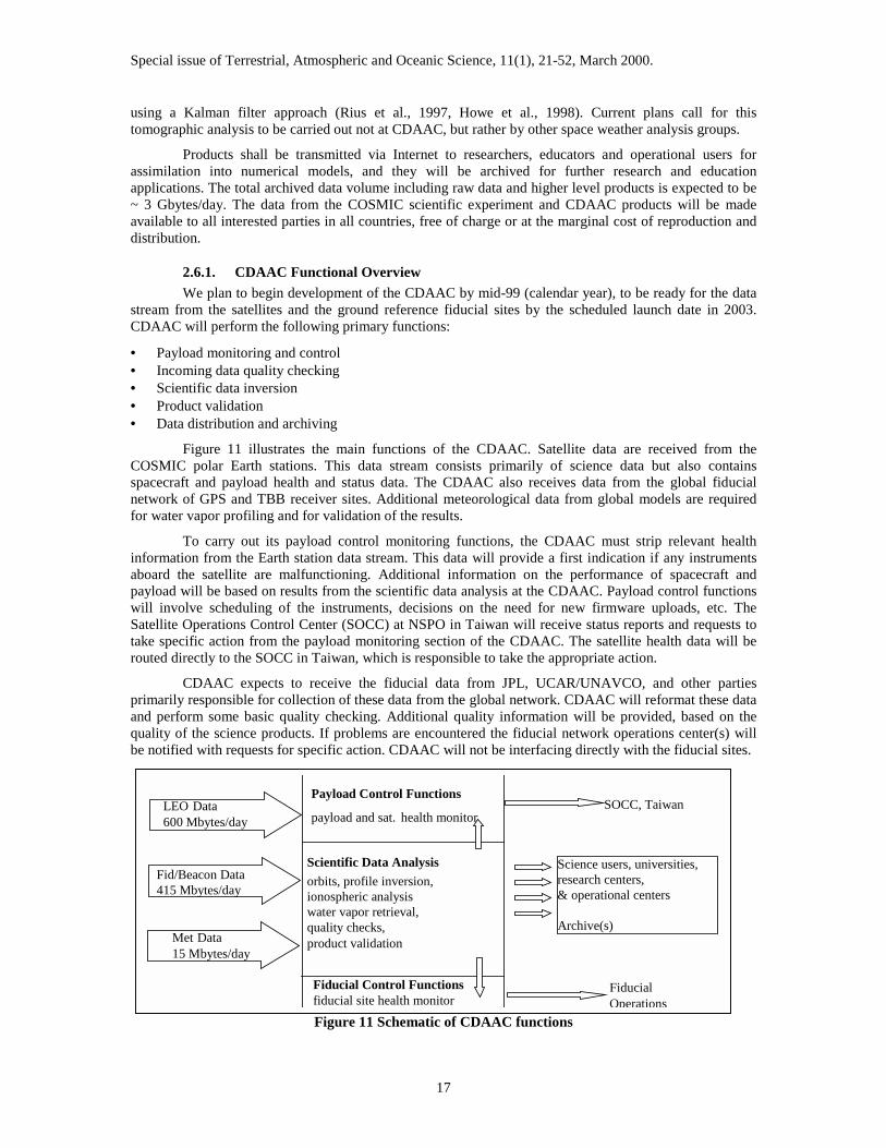
Figure 11 illustrates the main functions of the CDAAC. Satellite data are received from theCOSMIC polar Earth stations. This data stream consists primarily of science data but also containsspacecraft and payload health and status data. The CDAAC also receives data from the global fiducialnetwork of GPS and TBB receiver sites. Additional meteorological data from global models are requiredfor water vapor profiling and for validation of the results.
To carry out its payload control monitoring functions, the CDAAC must strip relevant healthinformation from the Earth station data stream. This data will provide a first indication if any instrumentsaboard the satellite are malfunctioning. Additional information on the performance of spacecraft andpayload will be based on results from the scientific data analysis at the CDAAC. Payload control functionswill involve scheduling of the instruments, decisions on the need for new firmware uploads, etc. TheSatellite Operations Control Center (SOCC) at NSPO in Taiwan will receive status reports and requests totake specific action from the payload monitoring section of the CDAAC. The satellite health data will berouted directly to the SOCC in Taiwan, which is responsible to take the appropriate action.
CDAAC expects to receive the fiducial data from JPL, UCAR/UNAVCO, and other partiesprimarily responsible for collection of these data from the global network. CDAAC will reformat these dataand perform some basic quality checking. Additional quality information will be provided, based on thequality of the science products. If problems are encountered the fiducial network operations center(s) willbe notified with requests for specific action. CDAAC will not be interfacing directly with the fiducial sites.
Payload Control Functions
17
Figure 11 Schematic of CDAAC functions
FiducialOperations
payload and sat. health monitorSOCC, TaiwanLEO Data
600 Mbytes/day
Scientific Data Analysisorbits, profile inversion,ionospheric analysiswater vapor retrieval,quality checks,product validation
Science users, universities,research centers,& operational centers
Archive(s)
Fid/Beacon Data415 Mbytes/day
Met Data15 Mbytes/day
Fiducial Control Functionsfiducial site health monitor
Special issue of Terrestrial, Atmospheric and Oceanic Science, 11(1), 21-52, March 2000.
18
By far most of the computing power and development effort will have to be invested in thescientific data analysis functions of CDAAC. Here the LEO data, the data from the fiducial network, andadditional meteorological data will be combined and inverted to obtain the COSMIC data products.
The CDAAC will generate results (products) on average within 3 hours of data collection.Additional high accuracy results will be computed for climate research after the highest accuracy post-processed satellite orbits are available from the International GPS Service (IGS) within about 1-2 weeksafter data collection. The IGS is also considering to compute LEO orbits (including COSMIC) and theseorbits may be used by CDAAC for its post processing of climate data.
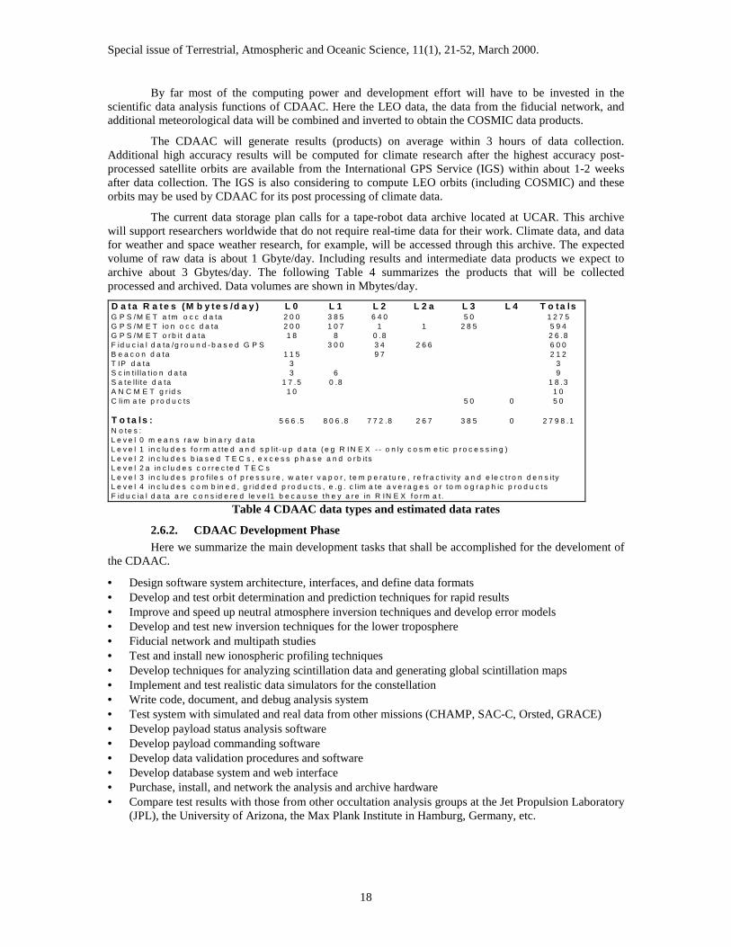
The current data storage plan calls for a tape-robot data archive located at UCAR. This archivewill support researchers worldwide that do not require real-time data for their work. Climate data, and datafor weather and space weather research, for example, will be accessed through this archive. The expectedvolume of raw data is about 1 Gbyte/day. Including results and intermediate data products we expect toarchive about 3 Gbytes/day. The following Table 4 summarizes the products that will be collectedprocessed and archived. Data volumes are shown in Mbytes/day.D a t a R a t e s (M b y t e s /d a y ) L 0 L 1 L 2 L 2 a L 3 L 4 T o ta lsG P S /M E T a tm o c c d a ta 2 0 0 3 8 5 6 4 0 5 0 1 2 7 5G P S /M E T io n o c c d a ta 2 0 0 1 0 7 1 1 2 8 5 5 9 4G P S /M E T o r b it d a ta 1 8 8 0 .8 2 6 .8F id u c ia l d a ta /g r o u n d - b a s e d G P S 3 0 0 3 4 2 6 6 6 0 0B e a c o n d a ta 1 1 5 9 7 2 1 2T IP d a ta 3 3S c in t i l la t io n d a ta 3 6 9S a te ll i te d a ta 1 7 .5 0 .8 1 8 .3A N C M E T g r id s 1 0 1 0C lim a te p r o d u c ts 5 0 0 5 0
T o t a ls : 5 6 6 .5 8 0 6 .8 7 7 2 .8 2 6 7 3 8 5 0 2 7 9 8 .1N o te s :L e v e l 0 m e a n s r a w b in a r y d a taL e v e l 1 in c lu d e s fo r m a t te d a n d s p lit - u p d a ta ( e g R IN E X - - o n ly c o s m e t ic p r o c e s s in g )L e v e l 2 in c lu d e s b ia s e d T E C s , e x c e s s p h a s e a n d o r b it sL e v e l 2 a in c lu d e s c o r r e c te d T E C sL e v e l 3 in c lu d e s p r o f i le s o f p r e s s u r e , w a te r v a p o r , te m p e r a tu r e , r e f r a c t iv i ty a n d e le c t r o n d e n s i tyL e v e l 4 in c lu d e s c o m b in e d , g r id d e d p r o d u c ts , e .g . c l im a te a v e r a g e s o r to m o g r a p h ic p r o d u c tsF id u c ia l d a ta a r e c o n s id e r e d le v e l1 b e c a u s e th e y a r e in R IN E X f o r m a t.
Table 4 CDAAC data types and estimated data rates
2.6.2. CDAAC Development PhaseHere we summarize the main development tasks that shall be accomplished for the develoment of
the CDAAC.
• Design software system architecture, interfaces, and define data formats• Develop and test orbit determination and prediction techniques for rapid results• Improve and speed up neutral atmosphere inversion techniques and develop error models• Develop and test new inversion techniques for the lower troposphere• Fiducial network and multipath studies• Test and install new ionospheric profiling techniques• Develop techniques for analyzing scintillation data and generating global scintillation maps• Implement and test realistic data simulators for the constellation• Write code, document, and debug analysis system• Test system with simulated and real data from other missions (CHAMP, SAC-C, Orsted, GRACE)• Develop payload status analysis software• Develop payload commanding software• Develop data validation procedures and software• Develop database system and web interface• Purchase, install, and network the analysis and archive hardware• Compare test results with those from other occultation analysis groups at the Jet Propulsion Laboratory
(JPL), the University of Arizona, the Max Plank Institute in Hamburg, Germany, etc.

Special issue of Terrestrial, Atmospheric and Oceanic Science, 11(1), 21-52, March 2000.
19
These development tasks require significant basic research in a variety of areas including: LEOand GPS orbit prediction, lower tropospheric signal penetration, water vapor determination, diffraction andmultipath correction, accounting for horizontal electron density gradients, ionospheric tomography,correction for systematic ionospheric solar cycle effects, data assimilation into numerical weather models.The COSMIC team at UCAR will investigate many of these issues. We will work closely with othergroups, such as the University of Arizona, Florida State University, the University of Texas, JPL, NRL, etc.to ensure that state-of-the-art algorithms are applied to the analysis of all COSMIC data. The mostimportant development tasks are described in more detail in the following sections.
2.6.2.1. Design System ArchitectureCDAAC system design is concerned with the data flow from the orbiting and ground-based
receivers all the way to the users and archive. We will collaborate with COSMIC system engineers andpayload developers on data formats, communication methods, and develop the software responsible forpulling in all the required Level 0 data at CDAAC. The software and interfaces to process all of the Level 0data will have to be designed at a functional level. Data reception latency, required processing time,hardware requirements etc. will have to be specified. The goal of this system architecture design is a fullyautomated front-to-end analysis system. CDAAC will generate products within about 40 minutes upon datareception and 3 hours of data collection on orbit. We will work with other UCAR programs on developingthe system for data archiving (UNAVCO) and for data distribution to the users (Unidata). The CDAACteam will also develop a web page to display real time global snapshots of, water vapor, temperature,tropopause height, geopotential height, electron density, and scintillation. This web page will become ahigh-visibility and dramatic showcase for the COSMIC mission.
2.6.2.2. Precision OrbitsFor precision analysis of occultation data, especially at altitudes between 30-60 km, LEO and GPS
satellite velocities have to be known to about 0.1 mm/s or better. This requires POD techniques that havebeen demonstrated during the GPS/MET experiment (Schreiner et al., 1998). The challenge for CDAACwill be to achieve this orbit quality close to real time. We will investigate two approaches to obtaininghigh-quality orbits in real time: (1) forward propagation of orbits (orbit prediction), and (2) orbitadjustment with the most recent data from the fiducial net and from the COSMIC satellites. While (1) willprovide faster results, (2) is expected to be more accurate. We need to investigate the optimal orbit strategyand implement it. CDAAC will use either the University of Berne developed Bernese software, or thecommercial MicroCosmTM software for POD.
It should be noted that accurate temperature and pressure profiles between 30-60 km, whileimportant for climate research and other science applications, are not as important for weather prediction asdata from the lower troposphere. Since temperature profiles in the lower troposphere are less sensitive toorbit errors it may be acceptable to relax real-time orbit requirements to 0.5 mm/s while maintaining thestricter requirements for post processing of climate products.
2.6.2.3. Improvements in neutral atmosphere analysisDuring GPS/MET we developed the analysis software package for neutral atmospheric inversions
described in Rocken et al. (1997). The CDAAC inversion software will build on that experience withseveral key improvements. The diffraction correction code developed for GPS/MET (Gorbunov andGurvich, 1998; Karayel and Hinson, 1997) was rather slow and seems to be sensitive to noise. This codewill have to be replaced with new and improved algorithms. We also will investigate different algorithmsfor extracting water vapor information from refractivity. One candidate is the adoption of FSU/NCAR's 1-dimensional variational (1-DVAR) data assimilation technique for the occultation analysis system (Zou etal. 1999, Kuo et al., 1998).
GPS/MET data analysis removes the ionospheric effect for neutral atmospheric profiling byforming a model-independent linear combination of the observed L1 and L2 bending angles (Vorob'ev andKrasil'nikova 1994). This correction mode leaves a small systematic residual error, depending on the levelof ionospheric activity. While this error is negligible in the lower troposphere it does affect stratospheric

Special issue of Terrestrial, Atmospheric and Oceanic Science, 11(1), 21-52, March 2000.
20
temperatures and it can have a long-term dependence on the 11-year solar cycle. Thus, to avoid aliasing ofthe solar cycle into the long-term climatological record of stratospheric temperatures from COSMIC, wewill develop a model-dependent 2nd order ionospheric correction that shall be applied in addition to the firstorder correction. We anticipate that this 2nd order correction will, to some extent, be based on the globalionospheric results from COSMIC and other occultation missions.
During GPS/MET we reported that occultation refractivity was often biased significantly lowerthan refractivity from correlative data (the so-called N-bias). We will pursue the investigation into this N-bias to make sure its cause is fully understood and that it will not affect COSMIC results. This task willinvolve simulating realistic occultation phase and amplitude data with a phase screen model (Gorbunov andGurvich, 1998) of the atmosphere and tracking that signal with the same firmware as used in the GPS flightreceivers.
Atmospheric inhomogeneity is the dominant error source for profiles of refractivity below 20 km,obtained with the standard Abel inversion technique. Resulting errors reach up to 10% near the surface(Kursinski et al., 1997). One way to avoid this error is to avoid the Abel inversion, and to assimilateprofiles of bending angles into numerical weather models (Eyre, 1994, Zou et al. 1999, 2000). The CDAACatmospheric scientist will work with NCAR's Mesoscale and Microscale Meteorology (MMM) Divisionand Florida State University (FSU) scientists on the development of these assimilation techniques.
For assimilation of the limb sounding data into atmospheric models the error estimates are asimportant as the observations. Significant effort will have to be invested by the CDAAC team to determinethe full error covariance of the COSMIC profile observations.
2.6.2.4. Analysis of open loop tracking in the lower troposphereFor meteorology it is of paramount importance to collect occultation soundings all the way to the
surface. During GPS/MET most soundings did not penetrate to the lowest km of the atmosphere. Forexample, during the time period in October 1995 (Rocken et al., 1997) only about 10% of all soundingsreached the lowest km. However, during an earlier time period in June 1995 almost 45% percent of theoccultations reached the bottom 1 km of the atmosphere. The difference can be attributed to the differentreceiver tracking firmware versions that had been uploaded to the orbiting receiver. Figure 12 shows thepenetration depth between (0-10 km) of all GPS/MET soundings that have been processed. Note that onlyvery few soundings reach the surface in tropical regions.
Figure 12 Penetration depth of GPS/MET project soundings.
The goal for COSMIC is to track 90% of all rising and setting occultation soundings into thelowest 1 km of the atmosphere. This will be achieved with (a) at least 10 dB higher gain antennae and (b)with "open loop" tracking in the lower part of the troposphere. While phase locked loops often cannot trackthe rapidly fluctuating signal in the lowest troposphere, open loop tracking is capable of tracking the phaseand amplitude of multiple tones (due to atmospheric multipath) independent of signal dynamics. Half of allprofiles will be from rising occultations. All rising occultations will start with open loop tracking data
Special issue of Terrestrial, Atmospheric and Oceanic Science, 11(1), 21-52, March 2000.
21
before the receiver can lock its loop several km above the ground. CDAAC scientists are developingsoftware to reconstruct the open loop data collected on orbit, and investigating open loop sampling rate andDoppler model requirements to allow reliable soundings to near the surface (Sokolovskiy, 2000a).
2.6.2.5. Fiducial Network StudiesDuring GPS/MET we observed high frequency Doppler phase errors, often as high as 1 mm/s and
in extreme cases 5 mm/s (Figure 7). As evidenced by daily repeatability with the well-known 4-minutesidereal day shift, these errors were caused by multipath reflections at the ground fiducial sites. Since theseerrors are large, compared to the required 0.1 mm/s satellite velocity errors, we will develop algorithms toreduce this effect. For this task we will explore the use of ground-site multipath correction maps, multipathmodeling, and filtering algorithms. COSMIC also needs to collaborate with the operators of the fiducialnetwork to encourage installation of low multipath fiducial sites for LEO mission support.
2.6.2.6. Ionospheric AnalysisThe assumption of spherical symmetry along the signal ray, as required by the Abel inversion
technique, is often invalid because of the very long, several 1000-km path lengths in the ionosphere. Aconstrained inversion technique (Hajj et al., 1994) can be applied to avoid this assumption. Schreiner et al.(1998, 1999) show that this technique, in order to improve upon the Abel inversion, requires a good firstguess of the ionospheric electron density gradients along the path transected by the occulting signal. EitherTIP measurements, or tomographic solutions of the ionosphere, or both can provide this a prioriinformation for COSMIC. Thus algorithms will have to be developed and implemented to combine GPSoccultation and TIP observations. Tomographic solutions will ingest GPS TEC data from LEO, TBB,ground based GPS TEC, and TIP data to produce estimates of 4 dimensional electron density fields, and ofGPS transmitter and receiver inter channel L1/L2 biases. We plan to implement these analysis techniques atthe CDAAC, using algorithms developed by ourselves and by our collaborators at NRL, at the Universityof Texas Applied Research Laboratory (ARL) and by the recently funded Global Assimilation ofIonospheric Measurements (GAIM) team.
2.6.2.7. Ionospheric ScintillationScintillation parameters will be computed on orbit from GPS SNR data, and will be forwarded to
the TBB ground receiver sites within ~ 10 min of the event (Figure 9). Additional scintillation data will beavailable from ground-based GPS and TBB receivers. These data will reveal the level of scintillation on thevarious transmission links, but not where the scintillation is occurring along the transmitter-receiver link. Inthe case when the region of the ionosphere containing irregularities is transected from several directions itis possible to locate a region causing scintillations through tomographic analysis. It is also possible tolocate the region containing irregularities along the line of site without multiple transecting rays. Twomethods for locating scintillation-causing irregularities will be developed both requiring phase andamplitude of the received signals and different techniques of back propagation. Note that these localizationtechniques will not be applicable within 10 minutes of the event because of the need for phase andamplitude data, which are not transmitted via the TBB modulation. The CDAAC team will provide adatabase for the scientific investigation of irregularities of electron density in the ionosphere. Other groupswill generate operational communication outage maps using the CDAAC scintillation products.

Special issue of Terrestrial, Atmospheric and Oceanic Science, 11(1), 21-52, March 2000.
22
0 20 40 600
100
200
300
400
500
600
700
800
CAS
NR
(Vol
ts/V
olt)
time (sec) 0 20 40 60
0
100
200
300
400
500
600
700
800
CAS
NR
(Vol
ts/V
olt)
time (sec)
Figure 13: 50 Hz GPS C/A SNR data for neutral atmospheric profiles with and without evidence ofscintillation. The left panel shows the SNR data for occultation #0070 at a latitude of ~36 degreesnorth and a local time of approximately 22.5 hours. The computed S4 index over the first 20 secondsof data is 0.005. The right panel shows evidence of scintillation for occultation #0077 that occurred atlatitude 10 degrees South at a local time of near 23.5 hours. The computed S4 index for occultation #0077 over the first 20 seconds of data is 0.113. The drop in signal strength at ~35 seconds in bothpanels is caused primarily by defocusing as the signal enters the neutral atmosphere.
2.6.2.8. Software DevelopmentWe anticipate that about 60,000 lines of code will have to be written, debugged, and tested for a
highly accurate, automated, and reliable processing center. The main components of this system will berelated to the overall architecture, instrument state-of-health monitoring, data reformatting, orbit analysis,science data inversion, database and archive system, web interface and data distribution. The CDAAC teamwill develop the software under the Unix Concurrent Version System (CVS). Rigorous linking of sourcecode versions and input parameter file configuration to the scientific output will have to be implemented, asprocessing techniques will clearly evolve over the duration of the COSMIC mission. Both the CVS and theversion tracking were implemented and applied during GPS/MET and will be refined for COSMIC.
We plan to develop detailed documentation in HTML format. This documentation will be requiredfor the CDAAC team and shall also be used for training and instruction.
2.6.2.9. Software Tests: Real Data and Data SimulationsThe CDAAC inversion software will be tested with occultation data from other satellite missions.
We will test archived GPS/MET data, but also plan to use data from the missions Orsted, SUNSAT, SAC-C and CHAMP. These missions will be flown prior to COSMIC. Especially CHAMP is an important dataset for us to use to develop processing software for open loop tracking data in the lower troposphere, and totest new algorithms for improved diffraction and multipath correction. Thus, during the COSMICdevelopment phase, we plan to conduct scientific data analysis from several other campaigns. The resultsobtained from this analysis will be made available to interested science investigators, and compared withother groups.
The CDAAC team has installed a sophisticated data simulator for two main functions. Simulateddata will be used to test parts of the CDAAC system prior to launch to ensure reliability and processingspeed. We will simulate observations from the 8-satellite constellation, using NCEP or ECMWF 4-dimensional weather analysis output, and realistic ionospheric models. These simulations will help testimprovements in the inversion software. We plan to use the ESA-developed EGOPS data simulator, which
Special issue of Terrestrial, Atmospheric and Oceanic Science, 11(1), 21-52, March 2000.
23
has been made available including source code to the CDAAC team for collaborative research with ourcolleagues at the University of Graz, Austria.
2.6.2.10. Data ValidationCDAAC will compute two solutions, one in real-time and one post processed. These solutions will
undergo different data validation procedures. The real-time solutions will undergo internal quality checksand will be compared to global 12-hour forecasts. Internal quality checks will be based on signal to noiseratio, phase breaks (cycle slips), signal bending characteristics in the "zero bending" 60-80 km heightregion, ionospheric activity, and accumulated empirical error statistics.
Focussing and defocusing of the limb-sounding signal as it descends through the atmospherecauses amplitude fluctuations. During GPS/MET we developed algorithms to invert amplitude data intotemperature and refractivity profiles (Sokolovskiy, 2000b). These amplitude-derived profiles can be usedfor validating the phase derived profiles to detect large errors.
Post processed results will undergo the same tests plus much more extensive comparisons withcorrelative data, from radiosondes, ground-based GPS, Lidars, and space-based systems such as TOVSGOES, AIRS/AMSU. An important task during the CDAAC development phase will be to establish theautomated processes that collect the correlative data, populate the correlative database, and carry out thecomparisons by applying the appropriate interpolations in space and time.
Occultation analysis centers at JPL, the University of Arizona, in Europe, and elsewhere will alsoprocess COSMIC soundings. We plan to establish data comparison procedures with these centers.
2.6.2.11. Setup of CDAAC hardwareThe development tasks described above will be carried out on a smaller CDAAC development
system because we want to purchase the main analysis system as close to the launch date as possible. Weplan to execute the purchase and begin setup and networking about 9 months prior to launch. This willallow for sufficient time to install the software, test it on the operational system, test all connections to thedata sources, test collection of correlative data, and test the data distribution system. Our goal is to be readyto process all data immediately after launch.
The GPS/MET experience has taught us that this is very important. Only after the end of theGPS/MET mission did we notice that the JPL-developed firmware, which had been uploaded during theearly June-July, 1995 prime time period, allowed more reliable tropospheric penetration than the firmwarethat was used for the remaining 2 years of the mission. Had we been able to process, and validate largeamounts of data in near real time during the early part of the mission, we would have obtained significantlymore lower-tropospheric observations from GPS/MET.
2.6.2.12. Operating CDAACAlmost immediately upon launch the data from the satellites and the ground support network will
begin to flow to the CDAAC. Depending on the constellation design, it may take as long as 9-months forthe satellites to reach their final orbits and full global coverage. During this transition phase GPS data willalready be processed for gravity field improvement, satellite cross-checks, and for special occultationstudies. While the satellites remain closely clustered, 4000 daily occultations will occur over smaller,localized regions, affording a unique opportunity for data validation field campaigns, special tomographicstudies, and experiments to resolve fine scale atmospheric features. Transition phase and operational phasedata will all be analyzed in the same way, and the same main levels of products will be made available.
Special issue of Terrestrial, Atmospheric and Oceanic Science, 11(1), 21-52, March 2000.
24
3. Publications
Anthes, R., M. Exner, C. Rocken, and R. Ware, Results from the GPS/MET Experiment and PotentialApplications to GEWEX, GEWEX News, 7, 3-6, Feb., 1997.
Bernhardt et al., Two-dimensional mapping of the plasma density in the upper atmosphere withcomputerized ionospheric tomography (CIT), Physics of Plasmas, Vol.5., No. 5, pp. 2010-2021,1998.
Bust, G.S., J.A. Cook, G.R. Kronschnabl, C.J. Vasicek, and S. B. Ward, Int. J. Imag. Sys. Tech.., 5, 160-168, 1994.
Crook, N.A., Sensitivity of Moist Convection Forced by Boundary Layer Processes to Low-LevelThermodynamic Fields, Mon. Weather Rev., 124, 1767, 1996.
Eyre, J., Assimilation of radio occultation measurements into a numerical weather prediction system, Tech.Memo.199, Eur. Cent. For Medium Range Weather Forecasts, Reading, England, 1994.
Feng, D., B. Herman, M. Exner, B. Schreiner, R. Anthes, and R. Ware, Space-borne GPS Remote Sensingfor Atmospheric Research, Proceedings from Synthetic Aperture Radar and Passive MicrowaveSensing, 2584, 448-455, 1995.
Gorbunov, M.E., and A.S. Gurvich, Microlab-1 experiment: Multipath effects in the lower troposphere, J.Geophys. Res, 103, 13819-13826, 1998.
Gorbunov, M.E., A.S. Gurvich, and L. Bengtsson, Advanced algorithms of inversion of GPS/MET satellitedata and their applications to reconstruction of temperature and humidity, Rep. 211, Max PlanckInst. For Meteorology, Hamburg, 1996.
Gurvich, A. S., and S. V. Sokolovskiy, Reconstruction of a pressure field by remote refractometry fromspace, Izvestya, Atm. and Ocean. Phys., 21, 7-13, 1983.
Hajj, G. A., R. Ibanez-Meir, E. R. Kursinski, L. J. Romans, Imaging the Ionosphere with the GPS,International Journal of Imaging Systems and Technology, Vol. 5, 174-184, 1994.
Hajj, G. A. and L. J. Romans, Ionospheric electron density profiles obtained with the GPS: Results from theGPS/MET experiment, Radio Science, Vol 33, No. 1, pp 175-190, Jan-Feb, 1998.
Hocke K., Inversion of GPS meteorology data, Ann. Geophys., 15, 443-450, 1997.Hoeg, P., A. Hauchecorne, G. Kirchengast, S. Syndergaard, B. Belloul, R. Leitinger, and W. Rothleitner,
Derivation of atmospheric properties using a radio occultation technique, Sci. Rep., 95-4, DanishMeteorol. Inst., 1996.
Howe, B.M., K. Runciman, J. A. Secan, Tomography of the ionosphere: Four-dimensional simulations,Radio Science, Vol 33, pp 109-128, 1998.
Kuo, Y.-H., X. Zou, and W. Huang, The Impact of GPS Data on the Prediction of an ExtratropicalCyclone: An Observing System Simulation Experiment, J. Dyn. Atmos. Ocean, 27, 439-470, 1997.
Kuo, Y.-H., X. Zou, S.-J. Chen, Y.-R. Guo, W. Huang, R. Anthes, D. Hunt, M. Exner, C. Rocken, S.Sokolovskiy, 1998: A GPS/MET sounding through an intense upper-level front, Bull. Am.Meteorol. Soc., 79, 617-626, 1998.
Karayel, E.T. and D. P. Hinson, Sub-Fresnel vertical resolution in atmospheric profiles from radiooccultation, Radio Sci. 32, 411-423, 1997.
Kursinski, E. R., G.A. Hajj, W. I. Bertiger, S. S. Leroy, T. K. Meehan, L. J. Romans, J. T. Schofield, D. J.McCleese, W. G. Melbourne, C. L. Thournton, T. P. Yunck, J. R. Eyre, R. N. Nagatani, InitialResults of Radio Occultation Observations of Earth’s Atmosphere Using the Global PositioningSystem, Science, 271, 1107-1110, 1996.
Kursinski, E.R., G.A. Hajj, J.T. Schofield, R.P. Linfield and K.R. Hardy, Observing the Earth’s atmospherewith radio occultation measurements using the Global Positioning System, J. Geophys. Res, Vol.102, NO. D19, pp 23429-23465, Oct. 20, 1997.
Lemoine, F.G., et al., The Development of the Joint NASA GSFC and the National Imagery and MappingAgency (NIMA) Geopotential Model EGM96, NASA/TP-1998-206862, 1998.
Leroy, S.S., The measurement of geopotential heights by GPS radio occultation, J. Geophys. Res., 102,6971-6986, 1997.
Leroy, S.S., Optimal detection of global warming using temperature profiles: A methodology, J. Climate,in press, 1998.
Lindzen, R.S., Some coolness concerning global warming, Bull. Am. Meteorl.. Soc. 71, 288, 1990.

Special issue of Terrestrial, Atmospheric and Oceanic Science, 11(1), 21-52, March 2000.
25
Melbourne, W., E. Davis, C. Duncan, G. Hajj, K. Hardy, E. Kursinski, T. Meehan, L. Young, and T.Yunck, The application of space borne GPS to atmospheric limb sounding and global changemonitoring, JPL Publ., 94-18, 147 pp., 1994.
North, G. R., and M. J. Stevens, Detecting climate signals in the surface temperature record, J. Climate, 11,563-577, 1998.
Richmond, A.D., and Y. Kamide, Mapping electrodynamic features of the high-latitude ionosphere fromlocalized observations: Technique, J. Geophys. Res., 93, 5741-5759, 1988.
Rind, D., Just add water vapor, Science, 281, 1152, 1998.Rius, A., G. Ruffini, and L. Cucurull, Improving the vertical resolution of ionospheric tomography with
GPS occultations, Geophysical Research Letters, Vol. 24, No. 18, pp 2291-2294, Sept 1997.Rius, A., G. Ruffini, and A. Romeo, Analysis of Ionospheric Electron Density Distribution from GPS/MET
Occultations, IEEE Trans. on Geoscience and Remote Sensing, Vol. 36, No. 2, Mar 1998.Rocken, C., R. Anthes, M. Exner, D. Hunt, S. Sokolovskiy, R. Ware, M. Gorbunov, W. Schreiner, D. Feng,
B. Herman, Y. Kuo, and X. Zou, Analysis and validation of GPS/MET data in the neutralatmosphere, J. Geophys. Res, Vol. 102, pp 29849-29866, 1997.
Schreiner, W.S.., D.C. Hunt, C. Rocken, S. Sokolovskiy, Precise GPS data processing for the GPS/METradio occultation mission at UCAR, Proc. Of the Institute of Navigation- Navigation 2000, LongBeach, CA, pp. 103-112, Jan 21-23, 1998.
Schreiner, W.S., S. Sokolovskiy, C. Rocken, and D. C. Hunt, Analysis and Validation of GPS/MET RadioOccultation Data in the Ionosphere, Radio Science, Vol. 34, No. 41, pp949-966, July-August,1999.
Schutz, B., P. Abusali, C. Schroeder, B. Tapley, M. Exner, R. McCloskey, R. Carpenter, M. Cooke, S.McDonald, N. Combs, C. Duncan, C. Dunn, and T. Meehan, GPS Tracking Experiment of a Free-Flyer Deployed From Space Shuttle, Proceedings of GPS-95, Institute of Navigation, 1995.
Solheim, J. Vivekanandan, F., R. Ware, and C. Rocken, Propagation delays induced in GPS signals by dryair, water vapor, hydrometeors, and other particulates, J. Geophys. Res., 104, No D8, pp 9663-9670, April 27, 1999.
Sokolovskiy S., Signal Dynamics and Measurement of Atmospheric Limb Sounding Signals in the lowerTroposphere, Radio Science, submitted, 2000a.
Sokolovskiy S., Inversions of Radio-Occultation Amplitude Data, Radio Science, in press, 2000b.Space Handbook, editors C. D. Cochran, D. M. Gorman and J. D. Doumoulin, Air University Press,
Maxwell AFB, Ala., January 1985.Stevens, M.J., Optimal climate signal detection in four dimensions, J. Geophys. Res. - Atmos. 104 No. D4,
pp. 4089-4099, Feb., 1999.Tsuda, T., Nishida N., Rocken C., R. Ware, A global morphology of gravity wave activity in the
stratosphere revealed by the GPS occultation data (GPS/MET), in print JGR, 2000.Voro’bev, V. V., and T. G. Krasil’nikova, Estimation of the Accuracy of the Atmospheric Refractive Index
Recovery from Doppler Shift Measurements at Frequencies used in the NAVSTAR System, Phys.of Atmos. and Oceans, 29, 602-609, 1994.
Ware, R., M. Exner, D. Feng, M. Gorbunov, K. Hardy, B. Herman, Y. Kuo, T. Meehan, W. Melbourne, C.Rocken, W. Schreiner, S. Sokolovskiy, F. Solheim, X. Zou, R. Anthes, S. Businger, and K.Trenberth, GPS Sounding of the Atmosphere From Low Earth Orbit: Preliminary Results,Bulletin of the American Meteorological Society, 77, 19-40, 1996.
Ware, R. H., C. Alber, C. Rocken, F. Solheim, Sensing integrated water vapor along GPS ray paths,Geophys. Res. Lett., Vol. 24, No. 4, pp 417-420, Feb. 15, 1997.
Yuan, L., R. A. Anthes, R. H. Ware, C. Rocken, W. Bonner, M. Bevis, and S. Businger, Sensing ClimateChange Using the Global Positioning System, Journal of Geophysical Research, 98, 14,925-14,937, 1993.
Zou, X. , Y.-H. Kuo, and Y.-R. Guo, Assimilation of Atmospheric Radio Refractivity Using aNonhydrostatic Mesoscale Model, Mon. Wea. Rev., 123, 2229-2249, 1995.
Zou, X., F. Vandenberghe, B. Wang, M.E. Gorbunov, Y.-H. Kuo, S.Sokolovskiy, J.C. Chang, J.G. Sela andR.A.Anthes, A ray-tracing operator and its adjoint for the use of GPS/MET refraction anglemeasurements. J. Geophys. Res.-Atmosphere, Vol 104, NO. D18, 22301-22318, 1999.
Zou, X., B. Wang, H. Liu, R. A. Anthes, T. Matsumura, and Y.-J. Zhu,: Use of GPS/MET refraction anglesin 3D variational analysis. Q. J. R. Met. Soc., (in press), 2000.


![II. HOLOGRAPHIC MODEL OF COSMIC - arXiv · In the holographic description of cosmic preheating proposed in an accompanied Letter [1], the ... description of cosmic preheating at strong](https://img.pdfslide.net/doc/110x75/5ae04ed67f8b9a5a668d62a2/ii-holographic-model-of-cosmic-arxiv-the-holographic-description-of-cosmic-preheating.jpg)