Embed Size (px)
DESCRIPTION
COST 286 Electromagnetic Compatibility (EMC) in Diffused Communication Systems Hamburg , 25th-26th November, 2004. Research on simulating radiowave propagation in closed environments. Kamil Staniec. Wroclaw University of Technology Institute of Telecommunication s and Acoustics - PowerPoint PPT Presentation
Citation preview
COST 286Electromagnetic Compatibility
(EMC) in Diffused Communication Systems
Hamburg, 25th-26th November, 2004
Wroclaw University of TechnologyInstitute of Telecommunications and AcousticsWybrzeże Wyspiańskiego 27, 50-370 Wrocław
Polande-mail: [email protected]
Research on simulating radiowave propagation in closed environments
Kamil Staniec
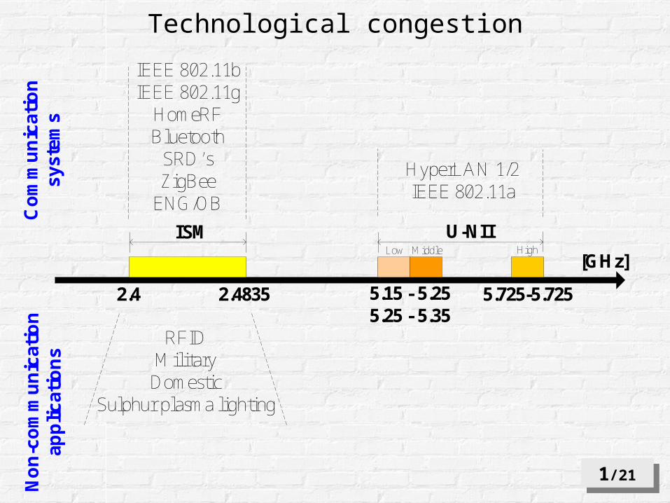
Technological congestion
1/211/21
2.4 2.4835 5.15 - 5.255.25 - 5.35
5.725-5.725
U-NIIISMLow Middle High
IEEE 802.11bIEEE 802.11g
HomeRFBluetooth
SRD’sZigBee
ENG/OB
HyperLAN 1/2IEEE 802.11a
Co
mm
un
icat
ion
syst
ems
No
n-c
om
mu
nic
atio
nap
plic
atio
ns
[GHz]
RFIDMilitary
DomesticSulphur plasma lighting
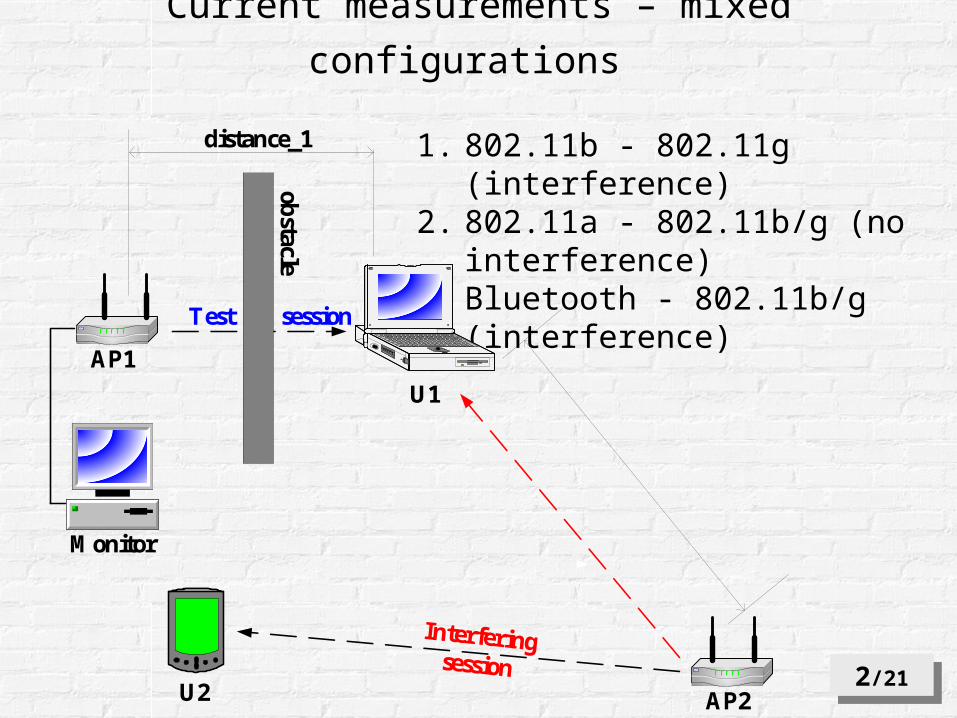
1. 802.11b - 802.11g (interference)2. 802.11a - 802.11b/g (no interference)3. Bluetooth - 802.11b/g (interference)
Current measurements – mixed configurations
Interferingsession
AP1
obstacle
distance_1
Monitor
U2 AP2
U1
Test session
2/212/21
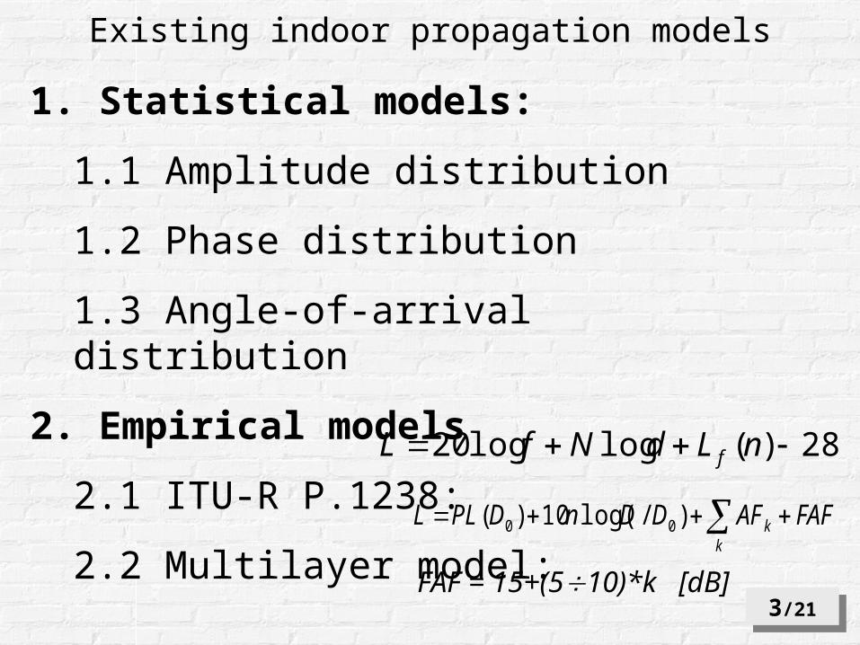
Existing indoor propagation models
1. Statistical models:
1.1 Amplitude distribution
1.2 Phase distribution
1.3 Angle-of-arrival distribution
2. Empirical models
2.1 ITU-R P.1238:
2.2 Multilayer model:
28)(loglog20 nLdNfL f
FAFAFDDnDPLLk
k )/log(10)( 00
FAF = 15+(510)*k [dB] 3/213/21
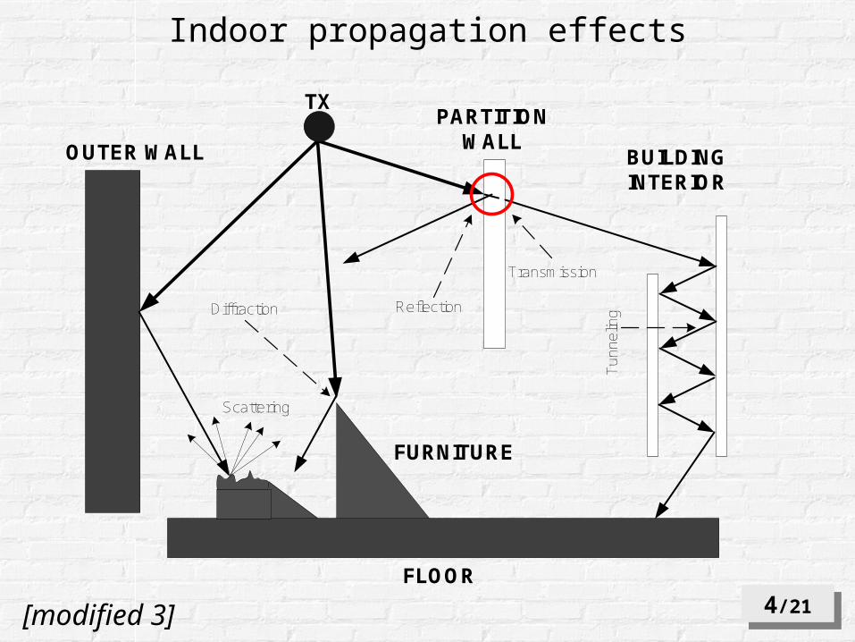
Indoor propagation effects
4/214/21
OUTER WALL
PARTITIONWALL
BUILDINGINTERIOR
FLOOR
TX
Transmission
Tun
nelin
gReflection
Scattering
Diffraction
FURNITURE
[modified 3]
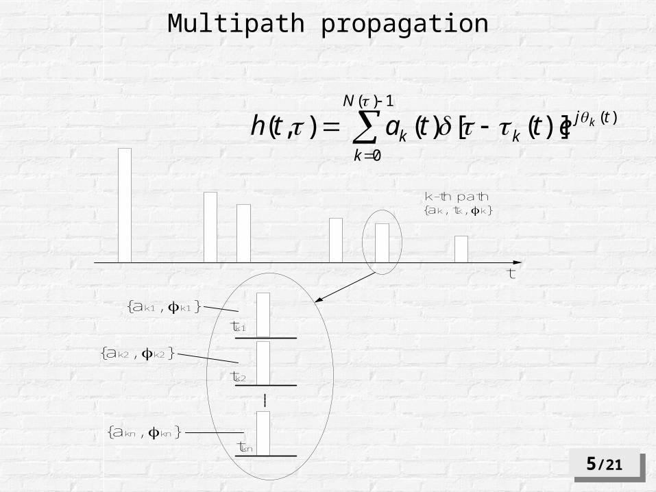
1)(
0
)()]([)(),(
N
k
tjkk
kettath
k-th path{ak, tk, k}
t
{ak1, k1}
{ak2, k2}
{akn, kn}
tk1
tk2
tkn
Multipath propagation
5/215/21
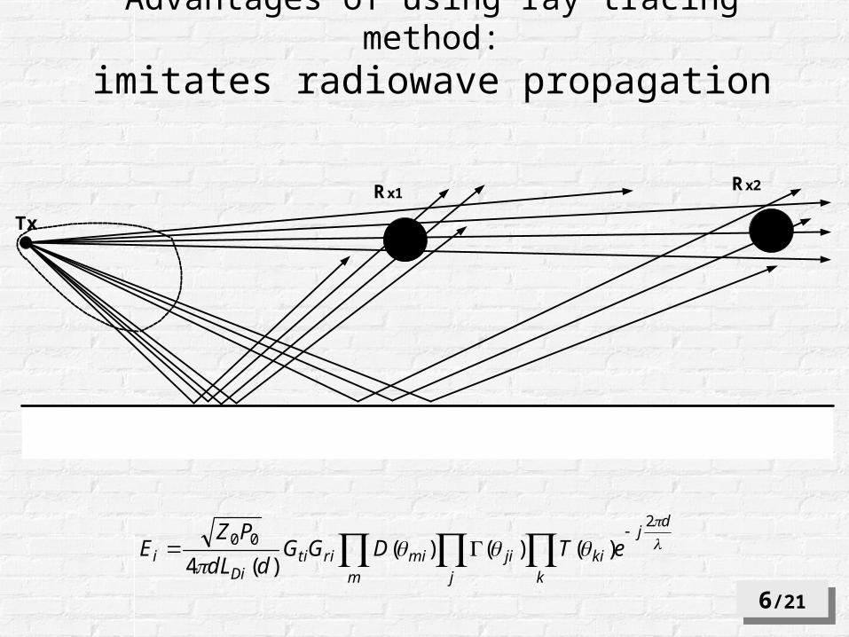
Advantages of using ray tracing method:imitates radiowave propagation
Tx
Rx1Rx2
k
dj
kij
jim
miritiDi
i eTDGGddL
PZE
200 )()()(
)(4
6/216/21
7/217/21
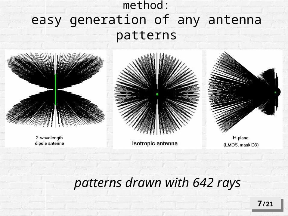
patterns drawn with 642 rays
Advantages of using ray tracing method:easy generation of any antenna patterns
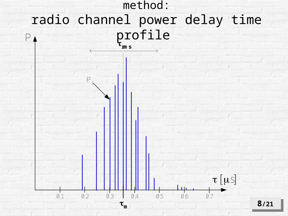
P
s
m
rms
0.1 0.2 0.3 0.4 0.5 0.6 0.7
Pi
8/218/21
Advantages of using ray tracing method:radio channel power delay time profile
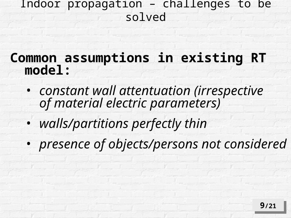
Indoor propagation – challenges to be solved
Common assumptions in existing RT model:
• constant wall attentuation (irrespective of material electric parameters)
• walls/partitions perfectly thin
• presence of objects/persons not considered
9/219/21
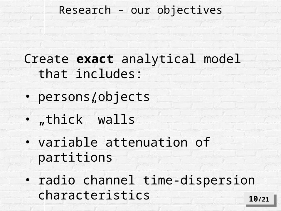
Research – our objectives
Create exact analytical model that includes:
• persons/objects
• „thick” walls
• variable attenuation of partitions
• radio channel time-dispersion characteristics
10/2110/21
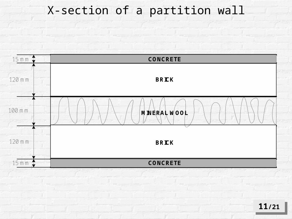
15 mm
15 mm
120 mm
120 mm
100 mm
CONCRETE
CONCRETE
BRICK
BRICK
MINERAL WOOL
X-section of a partition wall
11/2111/21
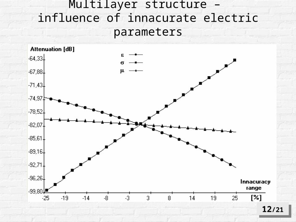
Multilayer structure – influence of innacurate electric parameters
12/2112/21
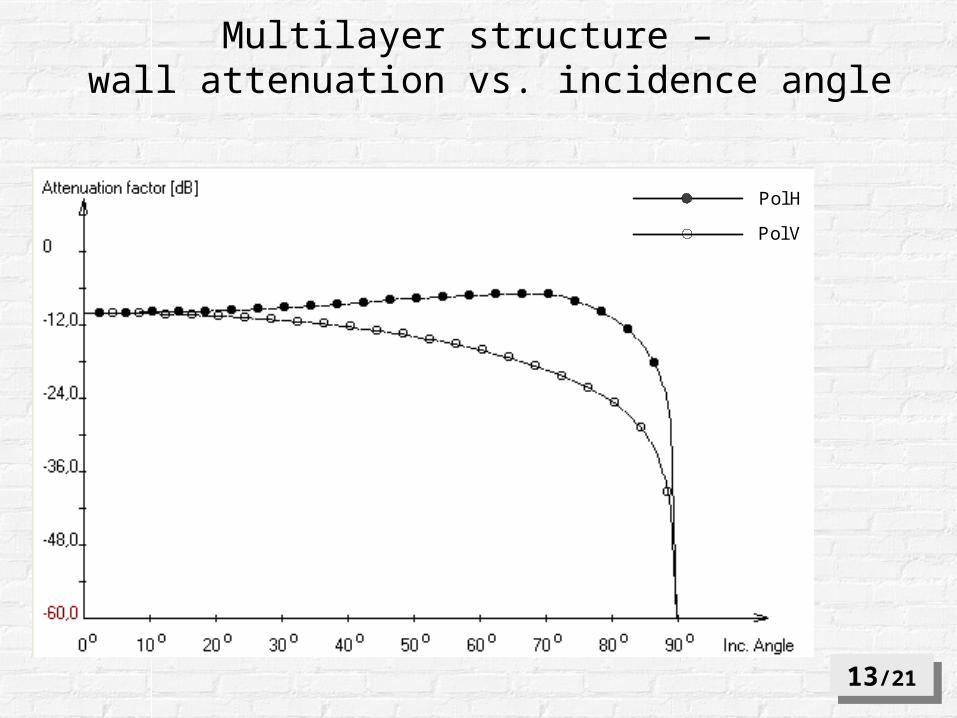
Pol H
Pol V
Multilayer structure – wall attenuation vs. incidence angle
13/2113/21
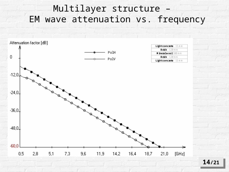
Light concrete 15 mm
Light concrete 15 mm
Brick 120 mm
Mineral wool 100 mm
Brick 120 mmPol H
Pol V
Multilayer structure – EM wave attenuation vs. frequency
14/2114/21
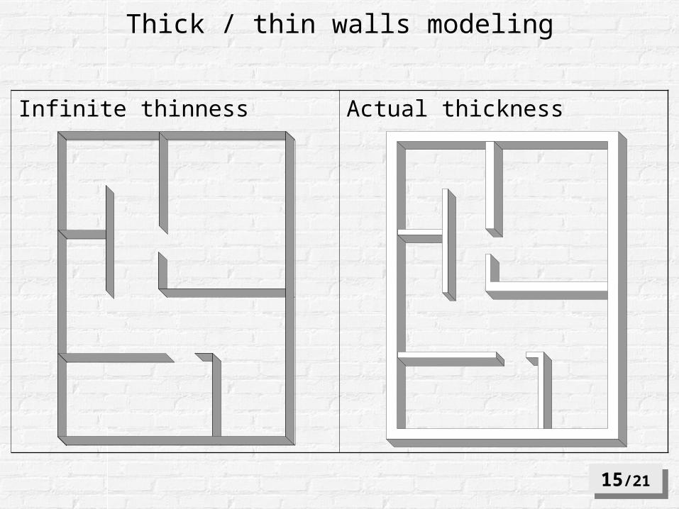
Infinite thinness Actual thickness
Thick / thin walls modeling
15/2115/21
11
2
12
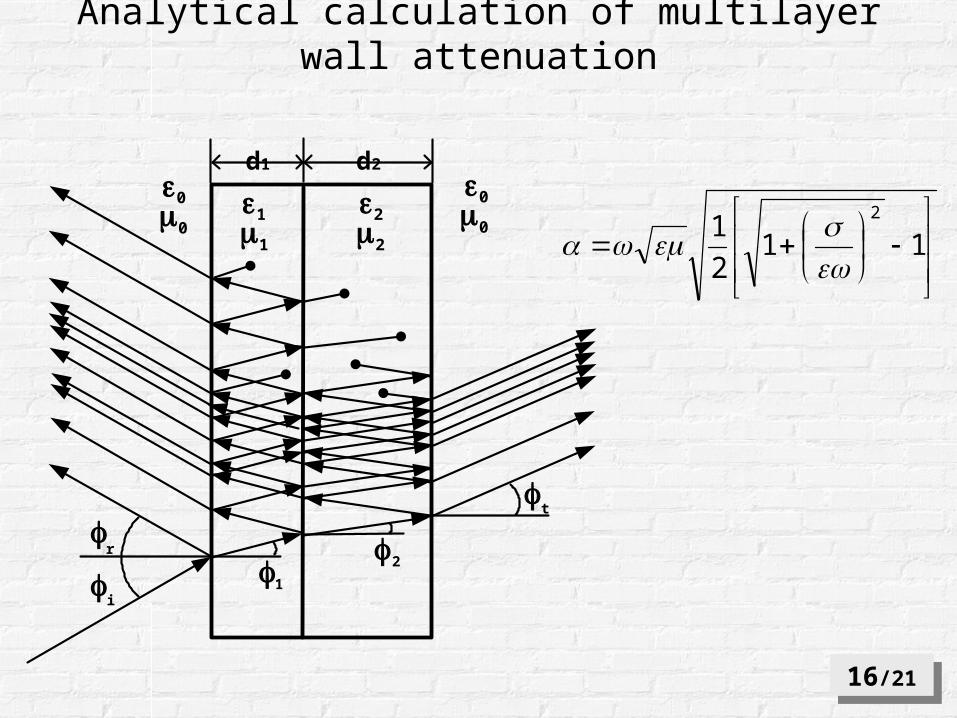
d1 d2
0 0
0 011
22
i
r
t
1
2
Analytical calculation of multilayer wall attenuation
16/2116/21
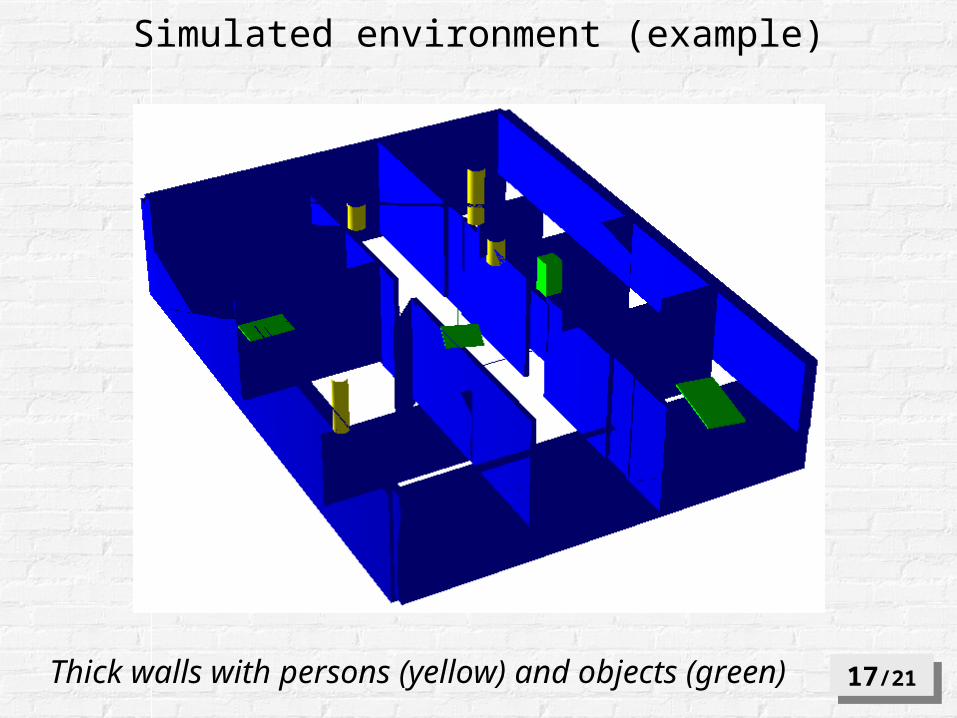
Thick walls with persons (yellow) and objects (green) 17/2117/21
Simulated environment (example)
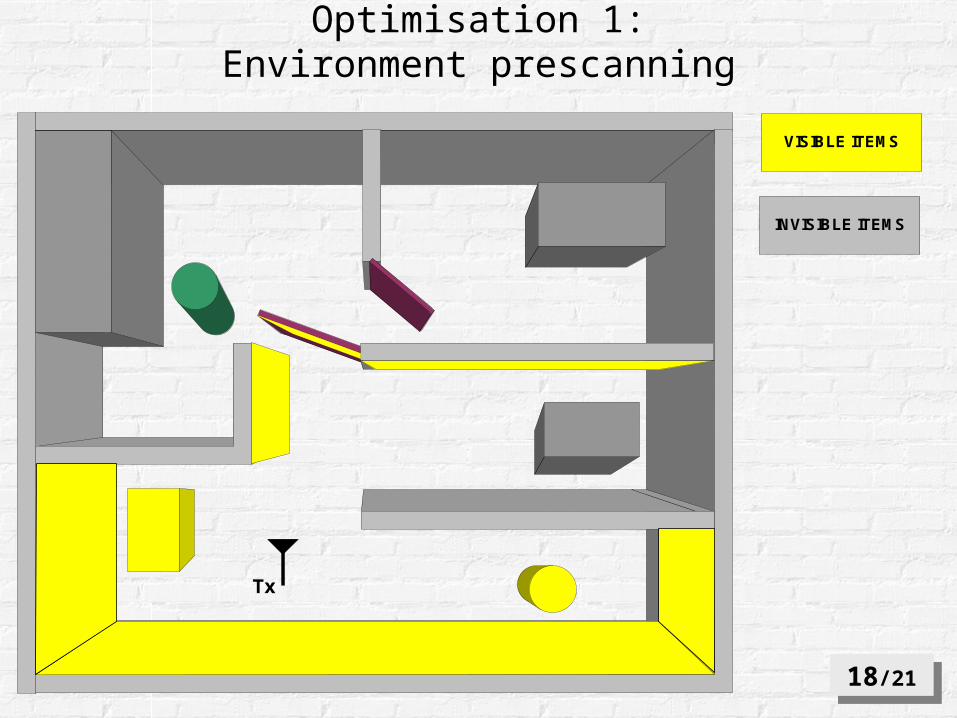
Optimisation 1:Environment prescanning
Tx
VISIBLE ITEMS
INVISIBLE ITEMS
18/2118/21
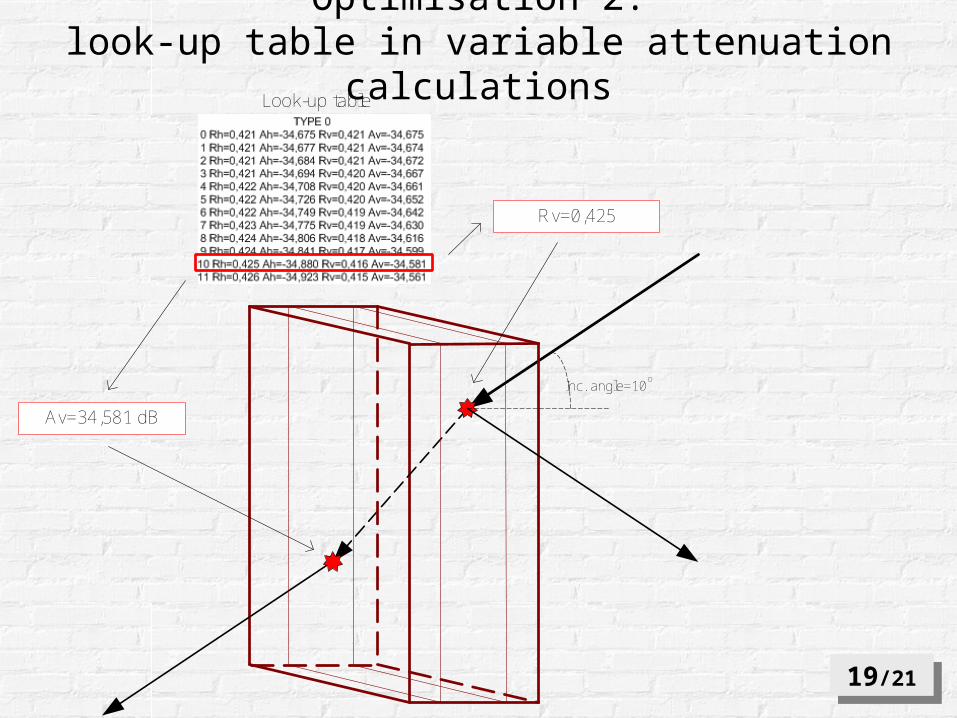
Rv=0,425
Av=34,581 dB
Look-up table
Inc. angle=10o
Optimisation 2:look-up table in variable attenuation calculations
19/2119/21
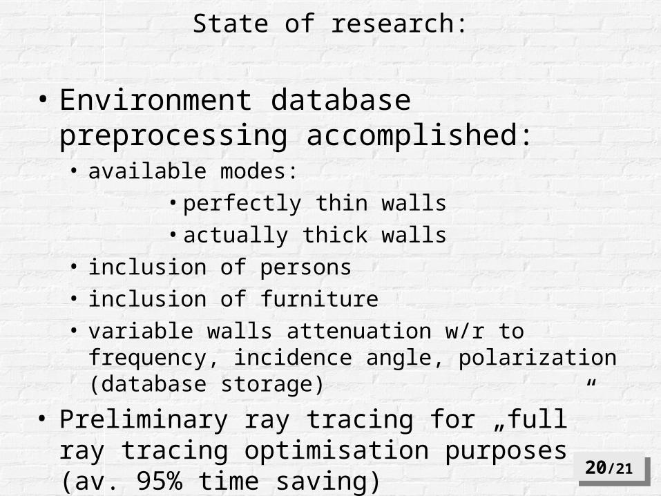
• Environment database preprocessing accomplished:• available modes:
• perfectly thin walls
• actually thick walls
• inclusion of persons
• inclusion of furniture
• variable walls attenuation w/r to frequency, incidence angle, polarization (database storage)
• Preliminary ray tracing for „full” ray tracing optimisation purposes (av. 95% time saving)
20/2120/21
State of research:
• e-field distribution maps in a closed environment (SOHO, vehicles, railway tunnels)
• information on radio channel dispersiveness - Power Delay Profile /available for each pixel/
• modeling mutual AP’s interference
21/2121/21
Possible applications:

THANK YOUTHANK YOU