Embed Size (px)
Citation preview
Cost-effective Designs for Supporting Correct
Execution and Scalable Performance in Many-core
Processors
by
Bogdan Florin Romanescu
Department of Electrical and Computer EngineeringDuke University
Date
Approved
Daniel J Sorin Advisor
Alvin R Lebeck
Christopher Dwyer
Romit Roy Choudhury
Landon Cox
Dissertation submitted in partial fulfillment of the requirements for the degree ofDoctor of Philosophy in the Department of Electrical and Computer Engineering
in the Graduate School of Duke University2010
Abstract(Computer engineering)
Cost-effective Designs for Supporting Correct Execution and
Scalable Performance in Many-core Processors
by
Bogdan Florin Romanescu
Department of Electrical and Computer EngineeringDuke University
Date
Approved
Daniel J Sorin Advisor
Alvin R Lebeck
Christopher Dwyer
Romit Roy Choudhury
Landon Cox
An abstract of a dissertation submitted in partial fulfillment of the requirements forthe degree of Doctor of Philosophy in the Department of Electrical and Computer
Engineeringin the Graduate School of Duke University
2010
Copyright ccopy 2010 by Bogdan Florin RomanescuAll rights reserved
Abstract
Many-core processors offer new levels of on-chip performance by capitalizing on the
increasing rate of device integration Harnessing the full performance potential of
these processors requires that hardware designers not only exploit the advantages
but also consider the problems introduced by the new architectures Such challenges
arise from both the processorrsquos increased structural complexity and the reliability
issues of the silicon substrate In this thesis we address these challenges in a frame-
work that targets correct execution and performance on three coordinates 1) toler-
ating permanent faults 2) facilitating static and dynamic verification through precise
specifications and 3) designing scalable coherence protocols
First we propose CCA a new design paradigm for increasing the processorrsquos life-
time performance in the presence of permanent faults in cores CCA chips rely on a
reconfiguration mechanism that allows cores to replace faulty components with fault-
free structures borrowed from neighboring cores In contrast with existing solutions
for handling hard faults that simply shut down cores CCA aims to maximize the
utilization of defect-free resources and increase the availability of on-chip cores We
implement three-core and four-core CCA chips and demonstrate that they offer a cu-
mulative lifetime performance improvement of up to 65 for industry-representative
utilization periods In addition we show that CCA benefits systems that employ
modular redundancy to guarantee correct execution by increasing their availability
Second we target the correctness of the address translation system Current
iv
processors often exhibit design bugs in their translation systems and we believe one
cause for these faults is a lack of precise specifications describing the interactions
between address translation and the rest of the memory system especially mem-
ory consistency We address this aspect by introducing a framework for specifying
translation-aware consistency models As part of this framework we identify the
critical role played by address translation in supporting correct memory consistency
implementations Consequently we propose a set of invariants that characterizes
address translation Based on these invariants we develop DVAT a dynamic veri-
fication mechanism for address translation We demonstrate that DVAT is efficient
in detecting translation-related faults including several that mimic design bugs re-
ported in processor errata By checking the correctness of the address translation
system DVAT supports dynamic verification of translation-aware memory consis-
tency
Finally we address the scalability of translation coherence protocols Current
software-based solutions for maintaining translation coherence adversely impact per-
formance and do not scale We propose UNITD a hardware coherence protocol
that supports scalable performance and architectural decoupling UNITD integrates
translation coherence within the regular cache coherence protocol such that TLBs
participate in the cache coherence protocol similar to instruction or data caches
We evaluate snooping and directory UNITD coherence protocols on processors with
up to 16 cores and demonstrate that UNITD reduces the performance penalty of
translation coherence to almost zero
v
To my grandparents
Bunicilor mei
vi
Contents
Abstract iv
List of Tables xi
List of Figures xii
List of Abbreviations xv
Acknowledgements xvi
1 Introduction 1
11 Processor Availability in the Presence of Hard Faults 3
12 Checking Correctness of Address Translation and Translation-AwareMemory Consistency 5
13 Scalable Translation Coherence Protocol Design 7
14 Thesis Statement and Contributions 9
15 Thesis Structure 11
2 Improving Lifetime Performance of Many-core Processors in thePresence of Hard Faults 12
21 Baseline System Model 14
211 Core Model 14
212 Core Shutdown Design 15
22 CCA Concept 15
23 CCA Design Decisions 17
24 CCA Implementations 18
vii
241 Baseline CS and CCA Cores 19
242 CCA3 3-Core CCA Implementation 20
243 CCA4 4-Core CCA Implementations 22
244 Many-core CCA Chips 27
25 Evaluation 27
251 CCA Chip Area Overhead 28
252 Lifetime Performance 29
253 Performance of Chips Using TMRDMR 37
26 Related Work 39
261 Multicore-Specific Self-Repair 39
262 Self-Repair for Superscalar Cores 39
263 Pooling of Core Resources 40
264 Lifetime Reliability 40
27 Conclusions 40
3 Address Translation-Aware Memory Consistency 42
31 AT Fundamentals and Assumptions 43
32 Memory Consistency Levels 45
33 Specifying PAMC 49
34 Specifying VAMC 50
341 Synonyms 50
342 Mapping and Permission Changes 52
343 LoadStore Side Effects 53
35 AT-aware VAMC Specifications 54
36 Commercial VAMC Models 56
37 Conclusions and Future Work 57
viii
4 Dynamically Verifying Address Translation 59
41 AT Model ATSC a Provably Sufficient Sequential AT Model 60
42 A Framework for Specifying AT Correctness 61
421 Page Table Integrity 62
422 Translation Coherence 63
43 DVAT Proposed Solution for Dynamic Verification of Address Trans-lation 65
431 System Model 66
432 DVATSC Overview 66
433 Implementation Details 69
44 Evaluation 70
441 Methodology 71
442 Error Detection Ability 72
443 Performance Impact 74
444 Hardware Cost 76
45 Related Work 76
46 Conclusions and Future Work 78
5 Unified Instruction Data and Translation Coherence Protocol 80
51 Existing Solutions for Maintaining Address Translation Coherence 81
511 TLB Shootdown 82
512 Performance Impact of TLB Shootdown 84
52 UNITD Coherence 87
521 Issue 1 Discovering the Physical Address of a Translationrsquos PTE 88
522 Issue 2 Augmenting the TLBs to Enable Access Using a PTErsquosPhysical Address 91
53 Platform-Specific Issues Implementation Issues and Optimizations 94
ix
531 Interactions with Speculative Execution 94
532 Handling PTEs in Data Cache and TLB 95
533 UNITDrsquos Non-Impact on the System 97
534 Reducing TLB Coherence Lookups 100
54 Experimental Evaluation 100
541 Methodology 100
542 Performance 103
55 UNITD Hardware Cost 111
56 Related Work 112
57 Conclusions and Future Work 113
6 Conclusions 116
Bibliography 121
Biography 134
x
List of Tables
11 Examples of Published Address Translation Design Bugs 6
21 Number of InputsOutputs per Stage for OR1200 21
31 SC PAMC Loads and stores are to physical addresses An X denotesan enforced ordering 49
32 Weak Order PAMC Loads and stores are to physical addresses Mem-Bar denotes a memory barrier An X denotes an enforced orderingAn A denotes an ordering that is enforced if the operations are to thesame physical address Empty entries denote no ordering 49
33 SC VAMC Loads and stores are to synonym sets of virtual addressesAn X denotes an enforced ordering 55
34 Weak Order VAMC Loads and stores are to synonym sets of virtualaddresses MemBar denotes a memory barrier An X denotes anenforced ordering An A denotes an ordering that is enforced if theoperations are to the same physical address Empty entries denote noordering 55
35 Address Translation in Commercial Architectures 56
41 Target System Parameters for DVATSC Evaluation 71
42 Scientific Benchmarks for DVATSC Evaluation 72
51 Target System Parameters for UNITD Evaluation 101
52 Microbenchmarks for UNITD Evaluation 101
xi
List of Figures
21 3-core CS Chip Generic cores have five pipe stages Fetch DecodeExecute Memory and Writeback Each core has one fault (Core 1in the Execute stage Core 2 in Writeback and Core 3 in Decode)rendering the chip useless 15
22 3-core CCA Chip Cores 1 and 3 are NC Core 2 is a CC The 2 NCsare functional leading to a non-zero chip performance 16
23 CCA3(21) Chip Cores 1 and 3 are NCs Core 2 is a CC Arrowsindicate the CC that provides spare components for each NC 21
24 CCA4 Chips CCs are colored Arrows indicate the CCs that providespare components for each NC 23
25 Input Buffering for CCrsquos Execute Stage 26
26 Output Buffering for CCrsquos Fetch Stage 27
27 CCA Designs Area Overhead Results are normalized with respect tothe areas of CS designs with the same number of cores 28
28 Performance of CCA Cores 31
29 Relative Delay for Accessing Cannibalized Stages Function of Tech-nology Node Results are normalized with respect to the clock periodsof the baseline core for the corresponding technology 32
210 Lifetime Performance of 3-core Chips 33
211 Lifetime Performance of CCA4-clock(22) Chips 34
212 Lifetime Performance of CCA4-clock(31) Chips 35
213 Lifetime Performance of CCA4-pipe(31) Chips 35
214 Lifetime Performance of Equal-Area Chips 36
xii
215 Lifetime Performance of TMR Chips 37
216 Lifetime Performance of DMR Pair Chips 38
31 Pseudo-code for a Generic MRF 44
32 Address Translation-Oblivious Memory Consistency 46
33 Address Translation-Aware Memory Consistency Shaded portions arethe focus of this chapter 46
34 Example of Synonym Problem Assume VAMC sequential consistencyand that VA1 and VA2 map to PA1 Assume that PA1 is initially zeroA naive VAMC implementation incorrectly allows (xy)=(21) 51
35 Power ISA Code Snippets to Illustrate the Need to Consider MRFOrdering Initially VA1 is mapped to PA1 and the value of PA1is A Enforcing MRF serialization through tlbsync (right-hand side)eliminates result ambiguity (left-hand side) 52
36 Code Snippet to Illustrate the Need to Consider LoadStore Side Ef-fects If the two instructions are reordered a Dirty bit set by the storecould be missed and the page incorrectly not written back 54
41 DVATSC rsquos Fault Detection Efficiency 73
42 DVATSC rsquos Bandwidth Overhead Compared to Baseline System 74
43 DVATSC rsquos Performance Impact Results are normalized to baselinesystem Error bars represent standard deviation 75
51 TLB Shootdown Routines for Initiator and Victim Processors 82
52 Average TLB Shootdown Latency on Xeon ProcessorsLinux Platform 85
53 TLB Shootdown Performance Overhead on Phoenix Benchmarks 86
54 3-level Page Table Walk in IA-32 UNITD associates PTE1 with theVP1rarrPP1 translation 89
55 PCAMrsquos Integration with Core and Coherence Controller UNITDintroduced structures are colored 92
56 PCAM Operations PA represents physical address 93
57 UNITD Speedup Over Baseline System for Single unmap Benchmark 104
xiii
58 Runtime Cycles Eliminated by UNITD Relative to Baseline Systemfor Single unmap Benchmark 105
59 UNITD Speedup Over Baseline System for Multiple unmap Benchmark106
510 UNITD Relative Bandwidth Consumption For Multiple unmap Bench-mark with Snooping Coherence Results are normalized to the baselinesystem 107
511 UNITD Speedup Over Baseline System for Single cow Benchmark 108
512 UNITD Speedup Over Baseline System for Multiple cow Benchmark 109
513 UNITD Relative Bandwidth Consumption for Multiple cow Bench-mark with Snooping Coherence Results are normalized to the base-line system 109
514 UNITD Speedup on Real Benchmarks 110
515 Percentage of TLB Coherence Lookups Filtered with a Simple JETTYFilter 111
xiv
List of Abbreviations
AT Address translation
CC Cannibalizable core
CS Core shutdown
DMR Dual modular redundancy
MRF Mapremap function
NC Normal core
PTE Page table entry
TLB Translation lookaside buffer
TMR Triple modular redundancy
SC Sequential consistency
xv
Acknowledgements
First and foremost I want to thank my parents for their support throughout my
graduate studies
My advisor Prof Daniel Sorin has been a continuous source of motivation and
mentoring I learned from Dan the art of abstracting concepts analyzing problems
rigorously and meaningful communication I thank Dan for his patience and guid-
ance in my development as a researcher I am grateful to Prof Alvy Lebeck for
the decision to join our research as his vast experience on architecture and systems
proved invaluable
I benefited from being part of a great computer architecture group at Duke The
reading group discussions helped me become a better critic and a sharper thinker
I was also fortunate to have two fantastic mentors during my summer internships
Jaidev Patwardhan and Anne Bracy Both Jaidev and Anne showed me the impor-
tance of being a good mananger in addition to being a skillful engineer
My student life would have certainly been duller if it werenrsquot for my colleagues
and friends In particular Vincent Mao has been a great office mate and I thank
him for all the time spent discussing not just research I am also grateful to Ionut
Constandache for sharing memories and thoughts
Finally I am forever in debt to Prof Calin Cascaval from TU Iasi for introducing
me to research and supporting me in pursuing my graduate studies
xvi
1
Introduction
Architects look ahead to many-core designs as the next standard of cost-effective
performance [53] Leveraging the still increasing rate of on-die transistor integra-
tion many-core processors are expected to feature hundreds to thousands of cores
[24] This order of magnitude increase in core count over existing processors offers
tremendous performance opportunities but also introduces new challenges for hard-
ware designers [15] Consequently architects must address issues such as scalability
power-efficiency and unreliability of the device substrate
This thesis proposes architectural solutions for some of these problems that af-
fect a processorrsquos correct execution and performance In particular we focus on
dependability and scalability issues Dependability encompasses a vast area of top-
ics including reliability maintanability and security We restrict our dependability
approach to two aspects availability and error detection Thus we address the chal-
lenges of many-core processors on three directions 1) availability in the presence of
permanent faults 2) supporting error detection through precise specifications and
3) designing scalable coherence protocols
Availability characterizes a systemrsquos capacity to function properly at a specific
1
time and is a function of the resources the system can provide to support correct
execution Availability is a primary concern for many-core processors given the in-
creased impact of permanent hardware faults (ie hard faults) and manufacturing
defects for deep-submicron technologies [25] Considering the increased density of
on-chip transistor integration these types of faults are expected to impact multiple
processor resources Designers must assume that such faults will occur during the
processorrsquos lifetime and propose architectural solutions to maximize the available on-
chip resources In Section 11 we describe a case for increasing processor availability
by tolerating hard faults in cores We propose handling such faults through a recon-
figuration mechanism that aggregates functional units from neighboring faulty cores
Our solution provides sustained availability and increases the processorrsquos expected
lifetime performance
A fundamental prerequisite for our availability solution is the systemrsquos ability to
detect incorrect execution in any of the processorrsquos components Incorrect execution
can be caused by either hardware faults or design faults which are introduced during
the design process Several efficient solutions exist for detecting faults in cores and
parts of the memory system [16 86 89] However in Section 12 we identify address
translation as one system for which no error detection solutions are currently avail-
able One possible cause for this lack of error detection mechanisms is the absence
of precise specifications of how the address translation system interacts with the rest
of the memory system and especially memory consistency We address this lack of
specifications by proposing a framework for specifying translation-aware consistency
models The critical role played by address translation in supporting memory con-
sistency motivates us to propose a set of invariants that characterizes the address
translation system Based on these invariants we develop a dynamic verification
solution for address translation which facilitates the runtime verification of memory
consistency
2
The last part of the thesis addresses the issue of scalable performance arguably
one of the most critical aspects of many-core processors design Integrating hundreds
of cores on the same die requires scalable interconnects and inter-core communication
mechanisms such as coherence protocols [15] Although architects have proposed scal-
able solutions with respect to these components [96 50 8 84] we identify translation
coherence as one area that has been generally neglected Software-based solutions
for maintaining translation coherence are performance costly and non-scalable and
no alternatives are currently available Section 13 argues that the time has come to
move translation coherence into hardware We propose one such solution by integrat-
ing translation coherence into the regular cache coherence protocol We implement
our solution on systems with both snooping and directory cache coherence protocols
and demonstrate that it reduces the performance penalty associated with translation
coherence to almost zero
Next we discuss in detail the motivation for the three research directions of this
thesis
11 Processor Availability in the Presence of Hard Faults
Deep-submicron technologies are characterized by an increased likelihood of hard
faults [42 120] Smaller transistors and wires are more susceptible to permanent
faults For pre-90nm technologies the degradation caused by such faults was small
enough to be accounted for in the componentrsquos testing margin such that it would not
affect the device functionality [25] However Srinivasan et al [120] demonstrated
that there is a sharp decrease in reliability beyond 90nm due to physical wearout
induced by time-dependent dielectric breakdown electromigration and stress migra-
tion Furthermore as we continue to add more transistors and wires there are more
opportunities for hard faults to occur either during fabrication or in the field [25]
Although current chips already incorporate mechanisms for addressing hard faults
3
most of them target SRAM structures This is a consequence of the memory cells
being more prone to faults than regular logic for pre-90nm technologies [52] Such
solutions for tolerating hard faults in memory structures include error correcting
codes and provisioning spare rowscolumns [77 26] The spare components can be
used to replace or remap few memory blocks transparently to the software such that
processorrsquos performance is virtually unaffected
In contrast processors have few if any solutions for tolerating hard faults in
cores The most common method of handling such faults is to disable either the
affected component or the entire core The former requires however that the faulty
component can be precisely identified and that the core contains replicas of the
unit The latter condition is difficult to satisfy even by superscalar cores as few
structures are replicated within the core [97] Consequently chip designers prefer
disabling the entire core a technique that is prevalently used by industry to increase
the chiprsquos manufacturing yield For example IBM markets Cell processors for Sony
Playstations with just 7 out of 8 functional SPEs [80]
The main drawback of disabling cores is that it reduces the availability of on-chip
resources leading to decreased overall processor performance Thus highly-available
systems rely instead on spare cores for delivering performance in the presence of
hard faults [17] Unfortunately spare components (either cold or hot) [10 117]
consume hardware resources that provide no performance benefit during fault-free
operation If we provision spares for all components then we achieve approximately
half the fault-free performance of an equal-area chip without spares The sparing cost
increases for systems that must tolerate multiple hard faults such as triple modular
redundant (TMR) systems [68]
In this thesis we address the inefficiencies of current solutions in providing cost-
effective availability in the presence of hard faults in cores by proposing the Core
Cannibalization Architecture (CCA) The CCA concept builds on the observation
4
that despite multiple hard faults in cores a chip provides enough fault-free resources
that can be aggregated to yield functional cores In Chapter 2 we propose and evalu-
ate various CCA designs that reuse components at the granularity of pipeline stages
We demonstrate that CCA significantly improves lifetime chip performance com-
pared to processors that rely on disabling cores In addition CCA can be combined
with solutions using redundant cores for increased processor availability
12 Checking Correctness of Address Translation and Translation-Aware Memory Consistency
In addition to permanent faults many-core processors face dependability concerns
due to transient faults and design faults [42 25] Similar to permanent faults tran-
sients are a consequence of the smaller transistor sizes which render chips more
susceptible to faults caused by neutrons and alpha particles [42] In contrast design
faults represent human errors and are rdquofacilitatedrdquo by increased design complexities
reduced testing time and imperfect coverage of random testing [66] Despite different
causes both types of faults have the same effect on a circuit resulting in incorrect
behavior
One of the systems that is currently vulnerable to these faults is address trans-
lation (AT) Representative of ATrsquos vulnerability is the disproportionate fraction of
published bugs in shipped processors [2 3 4 59 61 62 63] that involve AT hard-
ware including the infamous TLB coherence bug in AMDrsquos quad-core Barcelona
processor [131] Table 11 lists a few examples of these bugs
We believe that one of the underlying causes for ATrsquos reliability problems is the
designersrsquo tendency to over-simplify memory consistency and to neglect ATrsquos impact
on consistency models Current specifications do not provide a precise description
of the interactions between AT and the rest of the memory system Such clear
specifications of correctness are a fundamental prerequisite for detecting incorrect
5
Table 11 Examples of Published Address Translation Design Bugs
Processor Design Bug Effect
AMD Athlon64Opteron [2]
TLB flush filter may cause co-herency problem in multicore sys-tems
Unpredictable systemfailure (possible use ofstale translations)
AMD Athlon64Opteron [2]
INVLPG instruction with addressprefix does not correctly invali-date the translation requested
Unpredictable systembehavior (use of staletranslation)
Intel Core Duo[62]
One core is updating a page ta-ble entry while the other core isusing the same translation entrymay lead to unexpected behavior
Unexpected processorbehavior
Intel Core Duo[62]
Updating a PTE by changingRW US or P bits without TLBshootdown may cause unexpectedprocessor behavior
Unexpected processorbehavior
behavior
In Chapter 3 we propose a framework for precise implementation-independent
specification of AT-aware memory consistency We discuss in depth the memory con-
sistency levels that closely interact with the AT system We identify one particular
level that requires AT support and analyze the AT aspects that affect the consistency
specifications at this level
Our framework benefits both hardware designers and programmers Precisely
specifying the interactions between AT and the memory system reduces the proba-
bility of designers introducing design faults at this interface Second of all our spec-
ifications help system programmers in writing software that involves AT by clearly
stating the requirements for correct execution Finally the proposed framework
facilitates static verification and allows architects to develop checkers for runtime
verification of address translation
The important role that AT plays in supporting some levels of memory consis-
tency implies that a correct AT system is required for correct memory consistency
implementations To facilitate checking AT correctness we propose a framework
6
for AT specifications (Chapter 4) Based on this framework we create DVAT an
efficient dynamic verification scheme for AT coherence that can detect errors due to
design bugs and runtime faults We demonstrate that DVAT detects design bugs sim-
ilar to the ones reported in processor errata and supports comprehensive dynamic
verification of memory consistency
13 Scalable Translation Coherence Protocol Design
Our analysis of the AT system reveals that maintaining translation coherence has
a significant performance cost even for systems with few cores Translation caches
are just one of multiple types of caches that shared memory processors or multi-
processor systems must maintain coherent including instruction and data caches
While instruction and data cache coherence has been the focus of extensive research
on scalable coherence protocols [96 50 8 1 84 9] few solutions have been proposed
for scalable translation coherence [125] Designing a scalable protocol for translation
coherence requires us to first understand what essentially differentiates translation
coherence from instructiondata coherence
For caches that hold instructions or data coherence is almost generally main-
tained with an all-hardware cache coherence protocol Hardware controllers at the
caches coordinate amongst themselves using snooping or directories to ensure that
instructions and data are kept coherent and this coherence is not software-visible
However for caches that hold address translations (ie TLBs) coherence is almost
always maintained by an OS-managed software coherence protocol Even for archi-
tectures with hardware control of TLB fills and evictions when an event occurs that
affects the coherence of TLB entries (eg eviction of a page of virtual memory) the
OS ensures translation coherence through a software routine called TLB shootdown
[19]
Performing cache coherence in hardware provides two major advantages per-
7
formance and microarchitectural decoupling Performance-wise hardware is much
faster than software For coherence this performance advantage grows as a function
of the number of caches Although using software for local activities (eg TLB fills
and replacements) might have acceptable performance even some architectures that
have traditionally relied on software for such operations (eg SPARC) are now tran-
sitioning to hardware support for increased performance [95] In contrast activities
with global coordination are painfully slow when performed in software For example
Laudon [75] mentions that for a page migration on the SGI Origin multiprocessor
the software routine for TLB shootdown is three times more time-consuming than
the actual page move The second reason for performing cache coherence in hardware
is to create a high-level architecture that can support a variety of microarchitectures
A less hardware-constrained OS can easily accommodate heterogeneous cores as it
does not have to be aware of each corersquos particularities [71] Furthermore hardware
coherence enables migrating execution state between cores for performance thermal
or reliability purposes [34 51] without software knowledge
Given that hardware seems to be an appropriate choice for cache coherence
why has TLB coherence remained architecturally visible and under the control of
software We believe that one reason architects have not explored hardware TLB
coherence is that they already have a well-established mechanism that is not too
costly for systems with a small number of processors For previous multiprocessor
systems Black [19] explains that the low overhead of maintaining TLB coherence in
software on current machines may not justify a complete hardware implementation
As we show in the Section 512 this conclusion is likely to change for future many-
core chips
This motivates us to consider a hardware approach for translation coherence A
hardware TLB coherence protocol provides three primary benefits First it dras-
tically reduces the performance impact of TLB coherence While this performance
8
benefit is worthwhile on its own it also lowers the threshold for adopting features that
incur a significant amount of TLB coherence activity including hardware transac-
tional memory (eg XTM [40]) user-level memory management for debugging [43]
and concurrent garbage collection [39] Second hardware TLB coherence provides
a cleaner interface between the architecture and the OS which could help to reduce
the likelihood of bugs at this interface such as the recent TLB coherence bug in
the AMD Barcelona chip [131] Third by decoupling translation coherence from
the OS hardware TLB coherence can be used to support designs that use TLBs in
non-processor components such as network cards or processing elements [82 102]
This might facilitate a globally-shared address space among all components of a
computing system
Considering these advantages in Chapter 5 we propose UNITD a hardware co-
herence protocol that integrates translation coherence within the regular cache co-
herence protocol UNITD rdquosnoopsrdquo TLBs on regular coherence requests such that
any change to the page tables automatically triggers TLB coherence Relying on
small additional hardware UNITD successfully eliminates the performance cost as-
sociated with the TLB shootdowns routines In addition UNITD does not affect the
complexity or performance of the regular cache coherence protocol
14 Thesis Statement and Contributions
The imminent adoption of many-core processors as the next computing standard will
make these designs ubiquitous in our daily lives Such processors will have to support
a wide variety of applications ranging from systems that require correct execution
above all to applications that demand performance This observation motivates the
following thesis statement
The characteristics of many-core processors enable the design of cost-effective
solutions for supporting correct execution and performance given the reliability and
9
scalability challenges of these processors
To support this statement this thesis makes the following contributions in the
context of many-core processors
bull Proposes a solution to improve processorrsquos lifetime performance in
the presence of hard faults The dissertation introduces a low-cost and
efficient self-repair mechanism for many-core processors with simple cores by
enabling sharing of resources The reconfiguration solution provides sustained
performance and availability that outweigh the slight performance overhead in
fault-free scenarios over the processorrsquos lifetime
bull Develops a framework for specifying address translation-aware mem-
ory consistency models The framework analyzes the consistency levels
that closely interact with the address translation system and identifies the
translation-related aspects that impact consistency models Providing a thor-
ough multi-level specification of consistency enables programmers designers
and design verifiers to more easily reason about the memory systemrsquos correct-
ness
bull Proposes a dynamic verification scheme for address translation We
support the dynamic verification solution with an implementation-independent
framework for specifying address translation In addition to checking the cor-
rectness of the address translation system the proposed mechanism facilitates
comprehensive verification of memory consistency
bull Introduces a hardware coherence protocol for translation coherence
The proposed protocol integrates translation coherence into the existing cache
coherence protocol with TLBs participating in the protocol like instruction or
data caches Our hardware coherence protocol provides scalable performance
10
compared to existing software-based solutions for maintaining translation co-
herence
15 Thesis Structure
Chapter 2 describes CCA our solution for improving the lifetime performance of
many-core processors in the presence of hard faults Chapter 3 introduces the frame-
work for specifying translation-aware consistency models and analyzes the impact
of address translation on virtual address memory consistency Chapter 4 proposes
a framework for specifying address translation and details DVAT a dynamic veri-
fication mechanism for checking the correctness of the address translation system
Chapter 5 describes UNITD coherence a unified hardware coherence framework that
integrates instruction data and translation coherence in the same coherence protocol
Finally Chapter 6 summarizes the thesisrsquo contributions
11
2
Improving Lifetime Performance of Many-core
Processors in the Presence of Hard Faults
Technology trends are leading to an increasing likelihood of hard (permanent) faults
in processors [120] Traditional approaches to this problem include provisioning spare
components or simply disabling cores Unfortunately spare components (either cold
or hot) consume hardware resources that provide no performance benefit during
fault-free operation If we provision spares for all components then we achieve
approximately half the fault-free performance of an equal-area chip without spares
In turn core shutdown (CS) disables an entire core if any of its components has a
hard fault and thus wastes much fault-free circuitry
Motivated by the deficiencies of existing solutions our goal is to tolerate hard
faults in many-core processors without sacrificing hardware for dedicated spare com-
ponents There are two aspects to many-core processors that distinguish the issue
of self-repair from the case for single-core processors First power and thermal con-
straints motivate the use of simple in-order cores perhaps in conjunction with one
or two superscalar cores Examples of chips with simple narrow cores include the
UltraSPARC T1 [70] and T2 [112] Cray MTA [31] empowerTel MXP processor [54]
12
Renesas SH-2A-Dual [122] and Cisco Silicon Packet Processor [41] and we expect
this trend to continue for many-core processors Unfortunately simple cores have
little intra-core redundancy of the kind that has been leveraged by superscalar cores
to provide self-repair [27 113 119] Just one hard fault in the lone ALU or in-
struction decoder renders a simple core useless even if the entire rest of the core is
fault-free The second aspect of self-repair that is distinct to many-core processors
is the opportunity to use resources from fault-free cores
We propose the Core Cannibalization Architecture (CCA) the first design of a
low-cost and efficient self-repair mechanism for many-core processors with simple
cores The key idea is that one or more cores can be cannibalized for spare parts
where parts are considered to be pipeline stages The ability to use stages from other
cores introduces some slight performance overhead but this overhead is outweighed
by the improvement in lifetime chip performance in the presence of multiple hard
faults Furthermore CCA provides an even larger benefit for many-core chips that
use cores in a triple modular redundancy (TMR) or dual modular redundancy (DMR)
configuration such as Aggarwal et alrsquos approach [10] CCA enables more cores to
be operational which is crucial for supporting TMR or DMR
We develop several concrete implementations of CCA in the context of processors
that consist of up to four simple OpenRISC 1200 cores [74] We also present a
straightforward extension of these designs to many-core processors We show that
CCA achieves better performance than CS over the chiprsquos lifetime After only 2 years
CCA chips outperform CS chips Over a lifetime of 12 years CCA achieves a 63
improvement in cumulative performance for 3-core chips and a 64 improvement for
4-core chips Furthermore if cores are used redundantly (eg TMR or DMR) then
CCArsquos improvement is 70 for 3-core chips and 63 for 4-core chips
In this chapter after describing the baseline system model (Section 21) we detail
the CCA concept (Section 22) and discuss design-related aspects (Section 23) We
13
describe our CCA implementations in Section 24 We then evaluate CCA (Section
25) and compare it to prior research (Section 26) Finally we draw conclusions in
Section 27
21 Baseline System Model
In this section we present our core model and discuss core shutdown the natural
design point against which we compare
211 Core Model
In our analysis we focus on simple in-order cores with little redundancy We present
CCA in the context of 1-wide (scalar) cores but CCA also applies to many cores
that are wider but still have numerous single points of failure There are many k -
wide cores that cannot tolerate a fault by treating the core as being k-1 -wide For
example the Renesas SH-2A [122] is dual-issue but it has only one shifter and one
loadstore unit Any fault in either of those units renders the entire core unusable
Other simple cores are susceptible to numerous single faults (eg in the PC update
logic) that affect all lanes of the processor Many commercial cores fit our core model
[70 112 31 41] In addition Powell et al [97] show that non-redundant structures
represent the vast majority of core area even for superscalar cores
Our model assumes that the core has mechanisms for detecting errors and di-
agnosing hard faults (ie identifying the locations of hard faults) Detection and
diagnosis are orthogonal issues to self-repair and acceptable schemes already exist
such as the built-in self-test (BIST) used by the BulletProof pipeline [114] CCA
may require additional BIST test vectors than a baseline system to distinguish faults
that are in different pipeline stages and that would otherwise be exercised by the
same test vector CCA can also rely on software-based diagnosis solutions such as
the ones proposed by Hari et al [110] which eliminate the need for additional test
14
Figure 21 3-core CS Chip Generic cores have five pipe stages Fetch Decode ExecuteMemory and Writeback Each core has one fault (Core 1 in the Execute stage Core 2 inWriteback and Core 3 in Decode) rendering the chip useless
vectors
212 Core Shutdown Design
As mentioned in the chapterrsquos introduction a multicore processor with C simple
cores can tolerate hard faults in F (FltC ) distinct cores by simply not using the
faulty cores A single fault in a core renders the entire core useless Additional faults
in the same core (eg multiple faults can occur during the manufacturing process)
do not matter since the core has already been shut off The performance of a chip
with CS is proportional to the number of fault-free cores C -F Figure 21 illustrates
a 3-core processor with core shutdown In the presence of three hard faults one
in each core the processor achieves zero performance because none of its cores are
operable
22 CCA Concept
The CCA concept is based on the tight integration of the neighboring cores in a
many-core processor The key idea is that cores can be cannibalized for spare parts
by on-die adjacent cores to replace their own defective components and thus become
15
Figure 22 3-core CCA Chip Cores 1 and 3 are NC Core 2 is a CC The 2 NCs arefunctional leading to a non-zero chip performance
fault-free Thus a CCA system consists of a number of normal cores (NCs) that
cannot be cannibalized as well as some number of cannibalizable cores (CCs) We
use the notation CCAX(YZ) to refer to a CCA chip with a total of X cores out
of which Y are NCs and Z are CCs where X=Y +Z Similarly we use the notation
CSX to refer to a CS chip with X cores
At a high level a CCA processor resembles the system in Figure 22 The figure
illustrates a CCA system with three cores where Core 2 is a CC CCA enables Core
1 to overcome a faulty Execute stage and Core 3 to overcome a faulty Decode stage
by cannibalizing these stages from Core 2 The cannibalization process is facilitated
by a dedicated interconnect The result is that despite the presence of three hard
faults (including the fault in Core 2rsquos Writeback stage) Core 1 and Core 3 continue
to function correctly
The performance of both cores is somewhat degraded though because of the
delay in routing to and from the cannibalized stages However comparing the chips
in Figures 21 and 22 which both have three faults we see that CS offers zero
performance yet CCA provides the performance of two slightly degraded cores
16
In general as the number of faults increases CCA outperforms CS For chips
with zero or very few faults that do not allow CCA-type reconfigurations a pro-
cessor with CS outperforms CCA because CCArsquos reconfigurability logic introduces
some performance overhead into the cores This performance overhead is similar to
that incurred by schemes that provide spare components However as the number
of faults increases CCA can tolerate more of them and provide a graceful perfor-
mance degradation We demonstrate in Section 25 that over the chiprsquos lifetime the
expected performance of CCA chips exceeds the expected performance of CS chips
23 CCA Design Decisions
There are three important issues involved in a CCA design the granularity at which
to cannibalize cores the sharing policy between CCs and NCs and the assignment
of the chiprsquos cores to be either an NC or a CC After analyzing the first two issues
spare granularity and sharing policy we make fixed decisions for both of them For
the third issue chip layout we explore several options
Spare Granularity We cannibalize cores at the granularity of pipeline stages
The coarsest possible granularity is spare cores (ie CS) but coarse granularity
implies that a single fault in a core renders the entire core useless Finer granularity
avoids wasting as much fault-free hardware but it complicates the design especially
the routing to and from spare components For example one recent scheme for fine-
grain redundancy [93] has an area overhead that is greater than 2x We choose a
granularity of pipeline stages because it offers a good balance between complexity
and performance Our choice is confirmed by Gupta et al [48] that in a concept
similar to CCA determined that providing spares at pipeline stages granularity offers
the most cost-effective performance
Sharing Policy Another issue to resolve is whether to allow multiple cores to
simultaneously share a given component (ie pipeline stage for our implementation)
17
There are three options First at one extreme a core with a faulty component of
type Z rdquoborrowsrdquo (time multiplexes) a component of type Z from a neighboring core
that continues to function (ie is not cannibalized) A second option is to allow
multiple cores to time multiplex a single cannibalized component Both of these first
two options introduce resource contention require arbitration logic and complicate
pipeline control logic For these reasons we choose a third option in which any
given component can only be used by a single core
Chip Layout Categorizing the chiprsquos cores into CCs and NCs is crucial for the
increased performance of the CCA chip There are two aspects that influence CCArsquos
performance given a fixed core count The first is the number of cores that are CCs
Underprovisioning CCs leaves NCs without spare components while overprovisioning
CCs can lead to wasteful allocation of resources as the interconnection required for
providing access to CCs increases in complexity and size The second aspect is the
arrangement of NCs and CCs such that we minimize the distance between NC stages
and potential CC spare stages We must carefully balance the two aspects in order
to provide the best area-performance tradeoff Consequently we implement several
CCA designs based on different CCs-NCs configurations and compare them in terms
of performance and cost
24 CCA Implementations
In this section we first describe the cores used in our CS and CCA chips (Section
241) We then describe two concrete CCA implementations with three cores (Sec-
tion 242) and four cores (Section 243) respectively Based on these designs we
discuss how to extend CCA to chips with greater numbers of cores (Section 244)
A fundamental aspect in any CCA implementation is the latency of the intercon-
nect required for cannibalizing components The characteristics of this interconnect
are a function of low-level issues such as chip layout and wire delay Therefore a
18
proper evaluation of CCA requires us to implement the designs at a low level de-
tail We construct Verilog models for all designs we evaluate including systems with
and without CCA To evaluate area and delays we floorplan and layout chips using
Synopsys Design Compiler [123] and Cadence Silicon Ensemble [28] We use a pro-
prietary TSMC 90nm standard cell library for the synthesis flow Unfortunately the
library does not include memory cells and using regular flip-flops in synthesis creates
unrealistically large RAM structures and diminishes the impact of our changes In
order to provide a fair evaluation we estimate the size of the memory structures
using CACTI [92]
241 Baseline CS and CCA Cores
The core of the baseline CS processor is the OpenRISC 1200 (OR1200) [74] The
OR1200 core is a scalar in-order 32-bit core with 4 pipeline stages Fetch Decode
Execute and Writeback Each core has 32 registers and separate instruction and
data L1 caches (I-cache and D-cache) Implemented in our 90nm technology we can
clock the core at a maximum frequency of roughly 400MHz
The analysis of CCA cores is impacted by the implications of stage borrowing
An NCrsquos use of a cannibalized CCrsquos stage introduces issues that are specific to that
particular stage so we discuss next the cannibalization of each stage
Fetch The Fetch stage involves I-cache accesses If an NC uses a CCrsquos Fetch
stage it also uses the CCrsquos I-cache instead of its own cache
Decode The Decode stage is responsible for instruction decoding accessing the
register file and determining the destination address for jumpbranch instructions
A particularity of this stage is the branch destination (BD) block The OR1200
core has a one-instruction delay slot for branches and jumps and the BD block is
responsible for computing the address during the delay slot and communicating the
destination to the Fetch stage This block is tightly coupled with the Fetch stage
19
while operating independently from the rest of the decode logic Therefore due to
this tight coupling we consider the BD block as part of the Fetch stage An NC that
reuses the Fetch stage of a CC also reuses the CCrsquos BD block In addition to the BD
block the Decode stage includes the register file such that an NC that uses a CCrsquos
Decode stage also uses that CCrsquos register file In this case the NC must route back
to the CCrsquos register file during Writeback
Execute The Execute stage is where computations occur and where loads and
stores access the D-cache An NC that uses a CCrsquos Execute stage also uses that CCrsquos
D-cache the NC no longer uses its own D-cache
Writeback CCA does not require modifications for the Writeback logic but
it motivates a small change for register writing Because the register writing logic
is extremely small it is preferable in terms of area and performance to simply
replicate it (as a cold spare) in the original Writeback stage Intuitively forcing an
NC to go to a CC for a tiny piece of logic is not efficient If replication is not possible
due to possible area constraints this logic can be considered to be a component of
the Decode stage
242 CCA3 3-Core CCA Implementation
We first consider a 3-core chip that we refer to as CCA3(21) 2 cores are NCs and
1 is CC Our CCA3(21) implementation arranges the cores as shown in Figure 23
and we designate only the middle core Core 2 as a CC By aligning the cores in the
same orientation we facilitate routing from an NC to a CC By provisioning one CC
we obtain better chip performance than if we had implemented CCA3(12) which
would have 1 NC and 2 CCs With more than one CC the fault-free performance of
each core decreases due to added wires and multiplexing and the ability to tolerate
more faults does not increase much
If a single fault occurs in either Core 1 or Core 3 it is preferable to just not
20
13
Figure 23 CCA3(21) Chip Cores 1 and 3 are NCs Core 2 is a CC Arrows indicatethe CC that provides spare components for each NC
Table 21 Number of InputsOutputs per Stage for OR1200
Stage Input signals Output signals
Fetch 56 65Decode 38 115Execute 110 61Writeback 87 52
use that core rather than cannibalize Core 2 Not using a core leads to a total
chip performance of an NC and a CC combined while borrowing a stage yields a
chip performance of an NC and a borrowing NC As we show in Section 252 the
performance of an NC borrowing a stage is always lower than a fault-free CCA core
which is why we favor not using the faulty core
CCA3(21)rsquos reconfigurability requires some extra hardware and wires similar
to the overhead required to be able to use spare components Each NC (Core 1
and Core 3) has multiplexors (muxes) at the input to each stage that allow it to
choose between signals from its own other stages (the majority of which are from the
immediate predecessor stage) and those from the CC (Core 2) Similarly Core 2 has
multiplexors at the input to each stage that allow it to choose between signals from
its other stages and signals from the two NCs Table 21 shows the number of wires
that are the inputs and outputs of each stage
In CCA3(21)rsquos chip layout the distance to route from Core 1 or Core 3 to Core
21
2 and back is short The cores are small and the distance each way is approximately
1mm in 90nm technology Furthermore because these simple cores are designed for
power efficiency rather than for maximum clock frequency we do not expect them to
be clocked aggressively Thus given a clock frequency in the 400 MHz range and such
short wires the penalty of routing to and from a cannibalized stage is a relatively
small fraction of the clock period (as we show in Section 252) Rather than add
wire delay pipe stages to avoid lengthening the clock period (which we consider for
our 4-core implementations in Section 243) we simply slow the clock slightly For
chips with larger cores adding wire delay pipe stages may be preferable
One way to mitigate the impact of lengthening the clock period is to use clock
borrowing [129] Consider a fault in Core 1 If Core 1rsquos normal clock period is T
and its extra wire delay to and from Core 2 is W (for our CCA chips W is twice the
distance to access a spare component) then a simplistic solution is to increase Core
1rsquos clock period to Trsquo=T+W Clock borrowing can mitigate this performance impact
by amortizing time sharing W across the two neighboring stages [129] By sharing
this delay we can reduce the clock period penalty to 13 of W ie Trsquo=T+W 3
As a concrete example if Core 1 has a 50ns clock period (T=50ns) when fault-free
and W =15ns then we can use time borrowing to achieve a clock cycle of Trsquo=55ns
We borrow 5ns from both of the neighboring stages pushing them from 50ns to 55ns
Thus we have 65ns-10ns=55ns for the longer stage
243 CCA4 4-Core CCA Implementations
For the 4-core CCA chips we consider two viable CCA4 arrangements as illustrated
in Figure 24 CCA4(31) chips are natural extensions of the CCA3(21) chip In
addition we also propose the CCA4(22) configuration which has two cannibalizable
cores and differs from CCA4(31) in how CCs share stages In CCA4(22) Core 1
can use a stage from Core 2 or Core 3 Core 2 and Core 3 can use stages from each
22
13
(a) CCA4(22)
13
(b) CCA4(31)
Figure 24 CCA4 Chips CCs are colored Arrows indicate the CCs that provide sparecomponents for each NC
other and Core 4 can use a stage from Core 3 or Core 2 This sharing policy allows
CCs to share with each other and it allows the NCs to share from their more distant
CCs
An important distinction between CCA3 and CCA4 chips (of any kind) is that in
a CCA4 chip an NC may have to borrow a stage from a CC that is not an immediate
neighbor For example in Figure 24(b) Core 4 is approximately twice as far from
a CC as Core 3 is Furthermore as shown in Figure 24(a) a given NC might have
different distances to the two CCs (eg Core 4rsquos distance to Core 2 and Core 3)
The increase in distance from an NC to a CC may for some core microarchi-
tectures discourage the simple approach of lengthening the clock period of an NC
that is using a cannibalized stage In Figure 24(a) for example there might be
an unacceptable clock frequency penalty if we slow Core 1 to accommodate using a
cannibalized stage from Core 3 Based on this clock penalty we consider two ap-
proaches the clock period lengthening we have already discussed and adding clock
cycles to the pipeline The first approach sacrifices clock frequency while the second
approach sacrifices IPC and chip area The preferred approach in terms of overall
performance depends on the details of the core so we discuss both configurations
next
23
CCA4-clock
The CCA4-clock design relies on increasing the clock period for distant CC accesses
This design is advantageous when the performance penalty of slowing the clock is
preferable to adding pipeline stages The only new issue for CCA4-clock with respect
to CCA3 is that it is possible that we want to have different pipeline stages of the
same CC operate at different frequencies For example in Figure 24(b) if Core 1
is using Core 2rsquos Decode stage and Core 4 is using Core 2rsquos Execute stage then we
want Core 2rsquos Decode stage to be at a higher frequency than its Execute stage This
difference results from Core 4 being further from the CC than Core 1 is from the
CC Prior work has shown how to provide different clocks within a single core [67]
However if such a solution is considered too costly then Core 2rsquos clock frequency
must be lowered to match the lowest frequency needed such as the one imposed
by Core 4 in the example We use the CCA4-clock design for both CCA4(22) and
CCA4(31) configurations We refer to the latter as CCA4-clock(31) to differentiate
it from its CCA4-pipe implementation that we describe next
CCA4-pipe
The CCA4-pipe design like CCA3 assumes that routing from an NC to an imme-
diately neighboring CC can be efficiently accommodated by lengthening the clock
period of the NC and the CC However it allows routing from an NC to a CC that is
not an immediate neighbor to take one additional cycle and routing back from the
CC to the NC to account for another cycle We do not lengthen the clock because
the wire and mux delays fit well within a cycle for a simple relatively low-frequency
core To avoid adding too much complexity to the NCrsquos control we do not allow a
single NC to borrow more than one stage that requires adding cycles
When we add wire delay pipeline stages to a corersquos pipeline we must add extra
pipeline latches and solve four problems
24
1 Conditional Branch Resolution In the OR1200 the decision to take a branch
is determined by a single signal BranchFlag that is continuously propagated
from Execute back to Fetch This BranchFlag is explicitly setunset by instruc-
tions Because the OR1200 has a single delay slot the Fetch stage expects to
see a BranchFlag signal that corresponds to the instruction that is exactly
two instructions ahead of the current instruction in program order However
adding cycles between Fetch and Execute can cause the BranchFlag signal seen
by Fetch to be stale because it corresponds to an instruction that is more than
two cycles ahead of it To address this issue we slightly modify the pipeline
to predict that the stale BranchFlag value is the same as the value that would
have been seen in the unmodified pipeline We add a small amount of hardware
to remember the program counter of a branch in case of a misprediction If the
prediction is correct there is no penalty A misprediction causes a penalty of
two cycles
2 BranchJump Target Computation The target address is computed using a
small piece of logic in the Decode stage and having this unit close to the Fetch
stage is critical to performance As mentioned in Section 241 we treat this
logic separately from the rest of the Decode stage and we consider it to be
logically associated with Fetch Thus if there is a fault in the rest of the NCrsquos
Decode stage it still uses its original target address logic This design avoids
penalties for jump address computation
3 Operand Bypassing When an NC uses a CCrsquos Execute stage there are some
additional bypassing possibilities The output of the CCrsquos Execute stage may
need to be bypassed to an instruction that is in the wire delay stage of the
pipeline right before Execute Instead of adding a bypass path we simply
latch this data and bypass it to this instruction when it reaches the usual
25
13 Figure 25 Input Buffering for CCrsquos Execute Stage
place to receive bypassed data (ie when it reaches the Execute stage) We
also slightly modify the Decode stage to set the correct values for the signals
selecting the sources of the instructionrsquos operands
4 Pipeline Latch Hazards The extra stages introduce two structural hazards for
pipeline latches First if a cannibalized stage can incur an unexpected stall
then we must buffer this stagersquos inputs so they do not get overwritten For the
OR1200 Fetch and Execute require input buffering as illustrated in Figure 25
due to I-cache and D-cache misses respectively Second if a cannibalized stage
is upstream from (closer to Fetch than) a stage that can incur an unexpected
stall then the stall will reach the cannibalized stage late To avoid overwriting
the output of that stage we buffer its output For the OR1200 the Fetch and
Decode stages require output buffering (Figure 26) because the Execute stage
can stall on D-cache misses
If the area costs of buffering are considered unacceptably high it is possible to
squash the pipeline to avoid the structural hazards For example a D-cache
miss triggers a squash of younger instructions In our evaluation of CCArsquos
area we pessimistically assume the use of buffering rather than squashes even
26
13
Figure 26 Output Buffering for CCrsquos Fetch Stage
though squashing on D-cache misses would have no IPC impact on the OR1200
because the pipe would refill before the D-cache miss resolves
244 Many-core CCA Chips
Although we described until now CCA configurations with just three or four cores
CCA is easily extendable to many-core chips One feasible and straightforward way
to apply CCA to chips with more cores is to design these chips as groups of CCA3
or CCA4 clusters We leave for future work the exploration and evaluation of un-
clustered designs for chips with greater numbers of cores
25 Evaluation
Evaluating CCA designs requires us to consider two aspects First what is CCArsquos
design impact over the baseline chip in terms of area and clock period Second how
well do processors consisting of CCA3 and CCA4 clusters perform compared to CS
processors In this section we address both of these issues
27
13 13 13
Figure 27 CCA Designs Area Overhead Results are normalized with respect to theareas of CS designs with the same number of cores
251 CCA Chip Area Overhead
CCArsquos area overhead is due to the logic and wiring that enable stages from CCs
to be connected to NCs In Figure 27 we plot the area overheads (compared to
a CS chip with same number of cores) for various CCA chip implementations in
90nm technology These areas include the entire chip cores and the L1 I-caches
and D-caches which are both 8KB and 2-way set-associative (we do not consider L2
caches for our chips) We consider all of the following CCA designs CCA3(21)
CCA4-clock(31) CCA4-pipe(31) and CCA4-clock(22)
We observe that no CCA chip has an area overhead greater than 35 CCA3(21)
incurs less than 2 overhead which is a difference so small that it requires more than
50 cores on the chip (ie approximately 18 CCA3(21) clusters) before the addi-
tional area is equivalent to a single baseline core The CCA4 overheads are compara-
ble to the CCA3 overhead except for CCA4-pipe which requires some inputoutput
buffering and modified control logic in the cores
28
252 Lifetime Performance
The primary goal of CCA is to provide better lifetime chip performance than CS We
demonstrate in this section that CCA achieves this goal despite the small per-core
performance overheads introduced by CCA To better understand these results we
first present our fault model then evaluate fault-free single core performance (for
both NCs and CCs) and the performance of an NC using a cannibalized stage
We evaluate the performance for all cores and chips using the MediaBench bench-
mark suite [76] on the OpenRISC simulator [74] We consider a corersquos performance
to be the average runtime for all benchmarks in the suite relative to a baseline fault-
free OR1200 core (ie the relative average instructions per second (IPS)) Thus
the performance of a core is dictated by its frequency and the average IPC across
benchmarks We consider the performance of a fault-free OR1200 core to be 1 A
CCA core that yields the same average IPC but has a frequency of 10 less than
the baseline core has an overall performance of 09 The same performance charac-
terizes a core operating at the same frequency as the baseline OR1200 but that has
an average IPC degradation of 10
Fault Model
We consider only hard faults and we choose fault rates for each pipeline stage that
are based on prior work by both Blome et al [20] and Srinivasan et al [119] Blome
et al [20] decomposed the OR1200 core into 12 structures (eg fetch logic ALU
load-store unit etc) and for each structure determined its mean time to failure
in 90nm technology Their analysis considered the utilization of each structure and
they studied faults due only to gate oxide breakdown Thus actual fault rates are
expected to be greater [119] due to electromigration NBTI thermal stress etc
Srinivasan et al [119] assume that fault rates adhere to a lognormal distribution
with a variance of 05 The lognormal distribution is generally considered more
29
realistic for hard faults due to wearout because it captures the increasing rate of
faults at the end of a chiprsquos expected lifetime The variance of 05 is a typical value
for wearout phenomena By combining these two results we compute fault rates for
each pipeline stage We also consider faults in CCA-specific logic (including added
latches and muxes) and we assume that these faults occur at a rate that is the
average of the pipeline stage fault rates
As industrial data regarding failure rates is not publicly available in our experi-
ments we consider the above-mentioned fault rates to be the nominal fault rates and
we also explore fault rates that are both more pessimistic (2x and 4x nominal) and
less pessimistic (14x and 12x nominal) We assume that there are no faults present
at time zero due to fabrication defects The presence of fabrication defects would
improve the relative lifetime performance of CCA with respect to CS by reducing
the time until there are enough faults that CCA outperforms CS We also do not
consider faults in the cache interface logic which CCA could handle and thus we
slightly further bias our results against CCA
Fault-Free Single Core Performance
A fault-free NC or CC pays a modest performance penalty due to the multiplexors
that determine from where each stage chooses its inputs These muxes which affect
every pipeline stage require a somewhat longer clock period to accommodate their
latency Also CCArsquos additional area introduces some extra wiring delays but the
CAD tools revealed that this effect on the clock frequency is less than 03 The
mux delays are identical for NCs and CCs and they are not a function of the number
of cores or number of CCs In CCA3(21) each NC is choosing from among two
inputs (itself or the CC) The CC is choosing from among three inputs (itself and
both NCs) and thus has a 3-to-1 mux However at least one of those inputs is not
changing so the critical path of this 3-to-1 mux is the same as that of a 2-to-1 mux
30
1313
13
13
13
13
13
13
1313
13
Figure 28 Performance of CCA Cores
In the other CCA chips the NC and CC muxes are either 2-to-1 or 3-to-1 but we
can leverage the same observation about non-changing inputs Thus in all CCA
chips each NC and each CC has a clock period penalty that is equal to the latency
of one 2-to-1 mux This clock period penalty is 45 in 90nm technology
Single NC Performance When Using CC
An NCrsquos use of cannibalized stages introduces some performance degradation In
Figure 28 we plot the performance of an NC in several situations fault-free using
any immediate neighbor CCrsquos stage and extending the clock period and using a CCrsquos
stage and adding pipeline stages (ie for CCA4-pipe) Results are normalized to
the performance (instructions per second) of a single baseline core that has none of
CCArsquos added hardware We compute wire delays based on prior work by Ho et al
[58] and we assume that the wires between NCs and CCs are routed using middle
and upper metal layers We use a modified version of the OpenRISC simulator to
evaluate the IPC overhead for CCA4-pipe as a function of the cannibalized stage
The results show that when an NC borrows a CCrsquos stage the NCrsquos slowdown
is between 5 and 13 Most slowdowns are in the 10-13 range except when
31
13
13 13 13 13
13
13
13 13
Figure 29 Relative Delay for Accessing Cannibalized Stages Function of TechnologyNode Results are normalized with respect to the clock periods of the baseline core for thecorresponding technology
we add pipeline stages to borrow a Writeback stage extending the Writeback stage
incurs only a miniscule IPC penalty because exceptions are rare The performance
when slowing the clock to accommodate a borrowed stage (the second bar from
the left in Figure 28) is a function of the technology node In Figure 28 we as-
sume a 90nm technology For largersmaller CMOS technologies the wire delays are
smallergreater [58] Figure 29 shows the delay to access a borrowed stage across
different technologies Even at 45nm the delays remain under 15 and 19 for im-
mediate and non-immediate neighbors respectively Even the worst-case 19 clock
degradation for a core is still preferable to disabling the core
Lifetime Processor Performance
CCA addresses faults that occur over the lifetime of the processor and that have
a probabilistic rate of occurrence Therefore we consider in our evaluation a chiprsquos
expected lifetime performance as a consistent measure unit We extend the perfor-
mance definition for a single core and define chip performance as the aggregated
performance of the chiprsquos functioning cores A CS3 chip with no faults has an ex-
pected performance of 3 CCA3(21) with no faults has an expected performance
32
13
13
13
(a) Lifetime performance for nominal faultrate
13
13 13
13
(b) CCA3-clock(21)rsquos cumulative perfor-mance advantage compared to CS3
Figure 210 Lifetime Performance of 3-core Chips
of 285 due to CCA3(21)rsquos clock penalty for mux delays For brevity we refer to
rdquoexpected performancerdquo as simply rdquoperformancerdquo
To determine the aggregate chip performance in the presence of faults we use
Monte Carlo simulation We develop Petri Net models of the CS and CCA chips that
compute the expected performance of a chip as a function of time We model each
chip at the same 12-structure granularity as Blome et al [20] To evaluate a given
chip the Petri Net uses one million Monte Carlo simulations in which we inject hard
faults in each of the processor structures (including CCA logic and latches) using
the distributions previously specified (the million runs allow the results to converge)
Once a fault occurs in a structure the corresponding stage is considered unusable
For example a fault in the ALU triggers the failure of the Execute stage We do
not consider the time needed to detect failures and reconfigure the chip For each
experiment we report values after 6 and 12 years respectively since we consider that
a common industrial usage for a chip is between these time intervals
We first evaluate chips with an equal number of cores then compare performance
of equal-area chips
3-core Chips Figure 210 plots performance over the lifetime of the chips Fig-
33
13
13
13
(a) Lifetime performance for nominal faultrate
13
13
13
13
13
(b) CCA4-clock(22)rsquos cumulative perfor-mance advantage compared to CS4
Figure 211 Lifetime Performance of CCA4-clock(22) Chips
ure 210(a) shows the performance of 3-core chips assuming the nominal fault rate
The difference between the curves at time zero reflects CCArsquos fault-free performance
overhead We observe that the crossover point (ie the time at which the perfor-
mances of CS3 and CCA3(21) are identical) is at a little under 2 years After this
early crossover point CCA3(21)rsquos performance degradation is far less steep than
CS3rsquos The CCA3 chip does not become instantaneously more advantageous as it
still has to recoup the performance loss during the fault-free case For example after
6 years CCA3(21) outperforms CS3 by one fault-free baseline core
To better illustrate the importance of the gap between the curves in Figure
210(a) Figure 210(b) shows the cumulative performance for a variety of fault rates
The two bars for each fault rate represent the cumulative performance after 6 and
12 years respectively The cumulative performance is the integral (area under the
curve) of the performance in Figure 210(a) For nominal fault rates or greater
CCA3(21) provides substantially greater cumulative lifetime performance After
only 6 years at the nominal fault rate CCA3(21) has a 30 advantage and this
advantage grows to over 60 by 12 years Even at only half of the nominal fault
rate CCA3(21) has achieved a 30 improvement at 12 years For very low fault
34
13
13
13
(a) Lifetime performance for nominal faultrate
13
13
13
13 13
13
(b) CCA4-clock(31)rsquos cumulative perfor-mance advantage compared to CS4
Figure 212 Lifetime Performance of CCA4-clock(31) Chips
13
13
(a) Lifetime performance for nominal faultrate
13
13
13
13 13
13
(b) CCA4-pipe(31)rsquos cumulative perfor-mance advantage compared to CS4
Figure 213 Lifetime Performance of CCA4-pipe(31) Chips
rates CCA3(21) has slightly less cumulative performance after 6 years and slightly
more cumulative performance after 12 years but neither difference is substantial
4-core Chips We present the results for 4-core chips in Figures 211 212
and 213 respectively Similar to the CCA3 results the crossover point when CCA
chip outperforms CS is around 2 years for all CCA configurations (Figures 211(a)
212(a) and 213(a)) Figure 212(b) shows that CCA4-clock(31) achieves a greater
than 50 improvement in cumulative lifetime performance for the nominal and twice-
35
13
13 13 13 13
13
(a) 6-year cumulative results
13
13 13 13 13
13
(b) 12-year cumulative results
Figure 214 Lifetime Performance of Equal-Area Chips
nominal fault rates The results for the CCA4-pipe(31) are similar (Figure 213(b))
CCA4-clock(22) achieves the best performance improvement over CS by taking
advantage of the two CCs (Figure 211(b)) CCA4-clock(22) outperforms both
CCA4(31) configurations yielding improvements of 35 and 65 for the nominal
fault rates over 6 years and 12 years respectivelly
Equal-Area Comparisons The three-core and four-core results presented thus
far are not equal-area comparisons CCA chips are slightly (less than 35) larger
than CS chips To provide another comparison point we now compare chips of equal
area The ratio of the chipsrsquo performances is independent of the chip size Figure
214 plots the cumulative performance advantages of the CCA chips The figure
demonstrates that the CCA3(21) and CCA4-clock(22) configurations are the most
cost-effective designs for 90nm technology These results are quite similar to the
earlier results because CCArsquos area overheads are fairly small In addition we bias
the results against CCA by not considering L2 caches
36
13
13 13
13
13
(a) Performance for nominal failure rate
13
13
13
13
13
(b) CCA3-clock(21)rsquos cumulative perfor-mance advantage compared to CS3 forTMR configurations
Figure 215 Lifetime Performance of TMR Chips
253 Performance of Chips Using TMRDMR
We demonstrated that CCA outperforms CS chip by increasing core availability Sus-
tained availability is especially desired in fault tolerant architectures that use DMR
or TMR configurations to provide resilience against failures If multiple cores are
used to provide error detection with DMR or error correction with TMR then CCA
is beneficial as it allows for more cores to be available We consider the performance
of a chip to be the performance of the slowest core in a DMR or TMR configuration
If fewer than 2 cores are available the chip has zero performance (we assume the
user is unwilling to use the processor without at least DMR to detect errors)
TMR We plot the performance of 3-core chips that are being used in a TMR
configuration in Figure 215 The crossover point is at about 2 years similar to
the comparison between CCA3 and CS3 in non-TMR configurations However the
difference in cumulative performance is even greater CCA3 provides more than 50
more cumulative performance for nominal and higher fault rates even after only
6 years At just half of the nominal fault rate which is an optimistic assumption
CCA3 still has a 45 edge The intuition for CCArsquos large advantage is that it greatly
37
13
13
13
(a) Performance for nominal failure rate
13
13
13
13
13
(b) CCA4-clock(22)rsquos cumulative perfor-mance advantage compared to CS4 forDMR configurations
Figure 216 Lifetime Performance of DMR Pair Chips
prolongs the chiprsquos ability to operate in DMR mode This analysis also applies to
chips with more cores where the cores are grouped into TMR clusters
DMR We consider the performance of 4-core chips that comprise of two DMR
pairs of cores (ie 4 cores total) The first fault in any core leads to the loss of one
core and thus one DMR pair for both CS4 and CCA4 Additional faults however
are often tolerable with CCA4 Figure 216 shows the results for CCA4-clock(22)
which is the best CCA4 design for this situation Between approximately 2 and 25
years CS4 and CCA4-clock(22) have similar performances After that though
CCA4-clock(22) significantly outperforms CS4 The cumulative results show that
for nominal and greater fault rates CCA4-clock(22) provides lifetime advantages
greater than 35 over 6 years and greater than 63 over 12 years
Therefore CCA is especially beneficial in supporting the high-availability require-
ments of TMR and DMR configurations
38
26 Related Work
We compare CCA to prior work in self-repair pooling of core resources and lifetime
reliability
261 Multicore-Specific Self-Repair
Multicore processors are inherently redundant in that they contain multiple cores
Aggarwal et al [10] proposed a reconfigurable approach to using multiple cores to
provide redundant execution When three cores are used to provide TMR a hard
fault in any given core will be masked This use of redundant cores is related to
the traditional fault tolerance schemes of multi-chip multiprocessors such as IBM
mainframes [117] CCA is complementary to this work in that CCA enables a larger
fraction of on-chip cores to be available for TMR or DMR use Concurrently with our
work Gupta et al [48] developed the StageNet multicore processor that is similar
to the CCA concept [106] and in which the coresrsquo pipeline stages are connected by
routers The StageNet chip enables greater flexibility in sharing resources than CCA
but incurs a greater performance overhead for this flexibility Thus CCA processors
outperform StageNet ones for medium chip lifetimes of up to 10-12 years while the
latter outperform CCA chips over longer lifetimes
262 Self-Repair for Superscalar Cores
Numerous researchers have observed that a superscalar core contains a significant
amount of redundancy Bower et al [27] diagnose where a hard fault isndashat the gran-
ularity of an ALU reservation station ROB entry etcndashand deconfigure it Shivaku-
mar et al [113] and Srinivasan et al [119] similarly deconfigure components that
are diagnosed by some other mechanism (eg post-fabrication testing) Rescue [111]
deconfigures an entire rdquowayrdquo of a superscalar core if post-fabrication testing uncovers
a fault in it CCA differs from all of this work by targeting simple cores with little
39
intra-core redundancy Finally Powell et al [97] proposed thread migration if a hard
fault precludes the thread from executing on a core The fault-and-migrate technique
is efficient if the faulty unit is rarely used (ie the fault impacts only a rarely ex-
ecuted set of instructions) such that migration does not occur often Thus their
solution is targeted mostly towards multi-scalar cores and has limited applicability
to simple cores
263 Pooling of Core Resources
There have been proposals to group cores together during phases of high ILP Both
Voltron [134] and Core Fusion [65] allow cores to be dynamically fused and un-fused
to accommodate the software These schemes both add a substantial amount of
hardware to allow tight coupling of cores in the pursuit of performance and power-
efficiency CCA differs from this work by being less invasive CCArsquos goals are also
different in that CCA seeks to improve lifetime performance
264 Lifetime Reliability
Srinivasan et al [118 119] have explored ways to improve the lifetime reliability of a
single superscalar core These techniques include adding spare components exploit-
ing existing redundancy in a superscalar core and adjusting voltage and frequency
to avoid wearing out components too quickly CCA is complementary to this work
27 Conclusions
For many-core processors with simple cores there is an opportunity to improve life-
time performance by enabling sharing of resources in the presence of hard faults
The Core Cannibalization Architecture represents a class of designs that can retain
performance and availability despite such faults Although incurring slight perfor-
mance overhead in fault-free scenarios the CCArsquos advantages over the course of
40
time outweigh this initial disadvantage From among the CCA designs we believe
that CCA-clock designs are preferable to CCA-pipe designs Even in those situations
when CCA-pipe designs might yield a slightly better performance it is not clear that
their added complexity is worth this slight performance benefit However for future
CMOS technologies other core models or cores with faster clocks the CCA-pipe
design may be worth its complexity
Based on our results we expect CCA (or similar designs) to excel in two domains
in particular First for many embedded applications the key metric is availability
at a reasonable performance more so than raw performance Many embedded chips
must stay available for long periods of timendashlonger than the average lifetime of a
desktop for examplendashand CCA improves this availability Second the CCArsquos signif-
icant benefits for chips that use cores in TMR and DMR configurations suggest that
the design is a natural fit for chips using redundant cores to provide reliability
41
3
Address Translation-Aware Memory Consistency
Current processors are vulnerable to design bugs in their address translation (AT)
systems [2 3 4 59 61 62 63] Possible causes for the multitude and constant
occurrence of these design faults include the increased complexity of AT operations
as well as a lack of complete specifications for the interactions between the AT and
the rest of the memory system Such lack of precise specifications increases the
difficulty of ATrsquos pre-deployment testing and runtime verification Consequently we
are unaware of any existing dynamic verification solutions that target AT The result
is that the AT system is vulnerable to design bugs and any such design fault leads
to costly processor deployment delays as in the recent case of the TLB coherence
bug in the AMD Barcelona processor [131]
We believe that AT-related design bugs in modern processors are a direct re-
sult of designersrsquo tendency to over-simplify memory consistency and not account
for how it is impacted by AT Thus memory consistency is considered a mono-
lithic AT-independent interface between hardware and software In this chapter we
address this problem by developing a framework for specifying AT-aware memory
42
consistency models We expand and divide memory consistency into 1) the physical
address memory consistency (PAMC) model that defines the behavior of operations
on physical address and 2) the virtual address memory consistency (VAMC) model
that defines the behavior of operations on virtual addresses As part of this expan-
sion we show what AT features are required to bridge the gap between PAMC and
VAMC
This chapter is structured as follows We first describe the characteristics of the
AT system that we consider in our analysis (Section 31) We continue by discussing
the various levels of memory consistency that a system presents to its programmers
(Section 32) We then focus on the two consistency models that are closely related to
AT PAMC (Section 33) and VAMC (Section 34) and formalize the crucial role of
address translation in supporting a VAMC model We then show how AT-operations
can be integrated within a complete specification of VAMC models (Section 35) and
describe how commercially available systems handle AT-related operations (Section
36) Finally we discuss conclusions and future work (Section 37)
31 AT Fundamentals and Assumptions
Address translation is a level of indirection that regulates a software entityrsquos (ie
thread or process) access to physical memory given a virtual address We restrict our
discussion to page-based AT systems and leave as future work other virtual memory
paradigms such as segmentation Architectures facilitate this level of indirection
through translations which are supported by a set of software managed structures
called page tables
A translation is a tuple ltmapping(VPPP) permissions statusgt where the map-
ping converts the virtual page VP to a physical page PP PP permissions and status
information are specified by the page table entry (PTE) defining the translation and
that is uniquely identified by the VP This association is unique within the virtual
43
generic MRFacquire page table lock(s)createmodify the translationenforce translation coherence (eg send TLB invalidations to other cores)release page table lock(s)
Figure 31 Pseudo-code for a Generic MRF
memory context of the corresponding software entity The permission bits include
whether the page is owned by the user or the kernel and whether the page is readable
writeable or executable The status bits denote whether the page has been accessed
or is dirty In addition to these metadata bits translations also contain a Valid bit
that indicates if cores can access them in the page tables (ie the translations are
valid within the softwarersquos context) With respect to our analysis all operations
on this bit can be treated identically to operations on the mapping Therefore for
simplicity we do not consider separately the Valid bit in this chapter
Accessing a translation is on the critical path of a memory access for most systems
Consequently cores cache copies of the translations in private or shared translation
caches (ie translation lookaside buffersndashTLBs) to speed up translation accesses
Changes to the PTEs result in translations being modified or invalidated in the
page tables and coherence must be maintained between the cached copies of the
translations and the page table defined translations
Translation updates To create or delete a translation or to modify a trans-
lationrsquos mapping andor permission bits the privileged software (ie kernel) relies
on dedicated software routines that we refer to as mapremap functions (MRFs)
An MRF typically assumes the operations illustrated in Figure 31 Some of the
activities in an MRF require complicated actions to be performed by the software
or hardware For example ensuring translation coherence may require invalidating
copies of the translation from all TLBs This can be implemented by delivering TLB
44
invalidations through either inter-processor interrupts or a global TLB invalidation
instruction that relies on hardware for distributing the invalidations We discuss in
depth translation coherence in Chapter 5 while Section 51 describes the procedure
typically used for ensuring translation coherence
Status bits updates can be performed either explicitly by the kernel (ie priv-
ileged programmer) or implicitly by the system (ie hardware and possibly soft-
ware) Status bits updates are usually not performed in MRFs as they do not
require translation coherence and occur atomically for the TLB-cached translation
with respect to the memory PTE defining the translation In an architecture with
hardware-managed TLBs the hardware is responsible for eventually updating the
status bits If the TLBs are software-managed status bits updates occur in exception
handlers
ATrsquos System Impact AT encompasses both hardware and system software
and supports a systemrsquos virtual addresses memory operations By sustaining the
virtual address memory interface AT can impact two aspects that determine the
functionality of the memory system memory coherence and memory consistency
While memory coherence refers to the visibility of writes to a single memory location
by all cores in the system memory consistency specifies the order in which a corersquos
accesses to different locations in memory are observed by cores The focus of this
chapter is exclusively on ATrsquos impact on memory consistency motivated by the high
number of AT design faults that are related to this aspect
32 Memory Consistency Levels
A memory consistency specification defines the legal software-visible orderings of
loads and stores performed by multiple threads The consistency models serves as
a contract between the system and the programmer This contract is defined for
a specific memory interface and is valid only for the programmer operating at this
45
13
13
$amp
Figure 32 AddressTranslation-ObliviousMemory Consistency
13
13 13
13
13
13 13 13
13 13 13
13 13
13 13 13
13 13 13
13
Figure 33 Address Translation-Aware MemoryConsistency Shaded portions are the focus of thischapter
interface Therefore before specifying a consistency model it is crucial to determine
the interface at which the model applies to Given this observation in order to
understand ATrsquos impact on memory consistency we must consider the different levels
at which memory consistency specifications are defined and identify the ones that
are impacted by AT
The traditional view of memory consistency is that of one monolithic interface
between the hardware and the software as illustrated in Figure 32 Memory con-
sistency however is a set of interfaces between the hardware and various levels of
software as illustrated in Figure 33 These memory consistency layers are a di-
rect consequence of the different levels of abstractions that hardware and software
support in a computing system [115]
46
Although Adve and Gharachorloo previously explained the multi-level nature of
memory consistency [5] this more comprehensive definition of memory consistency
is not always adopted in the community For example classical architecture books
do not specify whether the model refers to virtual or physical addresses [54 115]
In addition existing consistency models such as sequential consistency (SC) proces-
sor consistency weak ordering release consistency etc do not distinguish between
virtual and physical addresses Lamportrsquos original definition of SC [73] is typical
in that it specifies a total order of operations (loads and stores) but it does not
specify whether the loads and stores are to virtual or physical addresses Implicitly
most existing consistency models assume either unmapped software or software with
a fixed one-to-one mapping from virtual to physical addresses We refer to these
consistency models as AT-oblivious
In contrast with AT-oblivious models understanding the impact of AT on mem-
ory consistency requires considering the hierarchical levels of memory consistency
models described in Figure 33 and identifying which of these levels are impacted by
AT At each of these levels the consistency model defines the legal orderings of the
memory operations available at that level We position hardware below all levels
as the microarchitecture represents the lowest level that provides mechanisms that
can be used to enforce consistency models at various levels (eg the core provides
in-order instruction commit) We limit our discussion to four levels relevant to pro-
grammers that are present in most current computing systems These consistency
models are necessary interfaces that are included in the specifications of the ISA
ABI and API However for the purposes of our current analysis we do not need
to consider which interfaces belong in which specifications We discuss these levels
starting at the lowest level
bull Physical address memory consistency (PAMC ) Some software such as un-
47
mapped code or boot code as well as the code managing the AT system rely
exclusively on PAMC Implementing PAMC is the hardwarersquos responsibility
and as such is specified precisely and completely in the architectural manual
(ie ISA)
bull Virtual address memory consistency (VAMC ) VAMC is the level just above
the PAMC All mapped software (ie software that executes using virtual ad-
dresses) relies upon VAMC including mapped system software VAMC builds
upon PAMC and requires support from both hardware and usually AT soft-
ware (we are unaware of a system that currently relies exclusively on hardware
for supporting VAMC although such a system might prove feasible to build
considering the increasing number of on-die available transistors) Perhaps one
non-intuitive aspect of VAMC is that mapped virtual memory system software
both relies upon VAMC and helps to support it
bull User process memory consistency (UPMC ) UPMC is specified by the software
whenever additional ordering is required on memory accesses beyond VAMC
Thus UPMC may either be identical to VAMC or it could differ as in the
case of software transactional memory or software distributed shared memory
bull High-level language consistency At the highest level user-level programmers
see the consistency model specified by the high level language [6] such as
the consistency models provided by C++ [23] or Java [83] These models
are supported by the compilers runtime systems and lower level consistency
models
As shown in Figure 33 PAMC and VAMC are important interfaces that support
different layers of software Correct PAMC is required for unmapped code to work
correctly and correct VAMC is required for mapped code to work correctly The AT
48
Table 31 SC PAMC Loads and stores are to physical addresses An X denotes anenforced ordering
Operation 2Load Store
Operation 1Load X XStore X X
Table 32 Weak Order PAMC Loads and stores are to physical addresses MemBardenotes a memory barrier An X denotes an enforced ordering An A denotes an orderingthat is enforced if the operations are to the same physical address Empty entries denoteno ordering
Operation 2Load Store MemBar
Operation 1Load A XStore A A XMemBar X X X
system intermediates the transition between the two consistency levels and directly
impacts the upper layer VAMC Without a correct AT system a system with virtual
memory cannot enforce any VAMC model
In the next sections we focus on these two consistency layers and explain how to
adapt well-known existing consistency models to these levels We present a VAMC
specification and show how it differs from PAMC discuss how AT bridges the gap
between PAMC and VAMC and describe how AT impacts both system programmers
and verification
33 Specifying PAMC
We specify consistency models at all levels using a table-based scheme like those of
Hill et al [56] and Arvind and Maessen [14] The table specifies which program
orderings are enforced by the consistency model Some consistency models have
atomicity constraints that cannot be expressed with just a table (eg stores are
atomic as is the case for TSO) We can specify these models by augmenting the table
with a specification of atomicity requirements as in prior work [14] although we do
49
not consider such models in this chapter
The specifications for PAMC can be straightforwardly adapted from the AT-
oblivious consistency model specifications by precisely stating that PAMC rules are
applicable to physical addresses only Thus for a sequentially consistent PAMC
model (SC PAMC) the specifications would state that (a) there must exist a total
order of all loads and stores to physical addresses that respects the program orders
of the threads and (b) the value of each load is equal to the value of the most
recent store to that physical address in the total order Table 31 presents the
specifications for the SC PAMC while Table 32 presents the adaptation for a Weak
Ordering PAMC respectively Under SC all physical address memory operations
must appear to perform in program order Under Weak Ordering memory operations
are unordered
34 Specifying VAMC
VAMC extends the PAMC specifications to also include mapped instructions Al-
though adapting an AT-oblivious consistency model for PAMC is straightforward
there are three challenges when adapting an AT-oblivious consistency model for
VAMC 1) synonyms 2) mapping and permission changes and 3) loadstore side
effects These challenges are based on AT aspects that directly impact VAMC or-
derings and we discuss both their impact on the programmer as regulated through
the VAMC interface as well as on the verification of the VAMC level
341 Synonyms
The first challenge is the possible existence of synonyms ie multiple virtual ad-
dresses (VAs) that map to the same physical address (PA) Consider the example in
Figure 34 in which VA1 and VA2 map to PA1 SC requires a total order in which
the value of a load equals the value of the most recent store to the same address
50
Thread 1 Thread 2
Store VA1=1Store VA2=2Load y=VA1
Load x=VA2
Figure 34 Example of Synonym Problem Assume VAMC sequential consistency andthat VA1 and VA2 map to PA1 Assume that PA1 is initially zero A naive VAMCimplementation incorrectly allows (xy)=(21)
Unfortunately naively applying SC at the VAMC level allows an execution in which
x=2 and y=1 The programmer expects that the loads in both threads will be as-
signed the value of the most recent update to PA1 However a naive definition of
VAMC that did not consider the level of indirection introduced by AT would allow
x to receive the most recent value of VA2 and y to receive the most recent value of
VA1 without considering that they both map to PA1 To overcome this challenge
we re-formulate AT-oblivious consistency models for VAMC by applying the model
to synonym sets of virtual addresses rather than individual addresses For example
we can define SC for VAMC as follows there must exist a total order of all loads
and stores to virtual addresses that respects program order and in which each load
gets the value of the most recent store to any virtual address in the same virtual ad-
dress synonym set Similar modifications can be made to adapt other AT-oblivious
consistency models for VAMC
Impact on Programming Programmers that utilize synonyms generally ex-
pect ordering to be maintained between accesses to synonymous virtual addresses
Incorporating synonyms explicitly in the consistency model enables programmers to
reason about the ordering of accesses to virtual addresses
Impact on VAMC Verification Explicitly stating the ordering constraints of
synonyms is necessary for verification An error in the address translation hardware
could result in a violation of ordering among synonyms that might not be detected
51
Buggy Code Correct Code
Thread 1 Thread 2 Thread 1 Thread 2
MRF map VA1 to PA2 MRF map VA1 to PA2tlbie VA1 invalidate tlbie VA1 invalidate
translation translation (VA1rarrPA1) (VA1rarrPA1)
tlbsync fence for MRF
sync memory barrier for sync memory barrier for regular memory ops regular memory ops
Store VA2 = B Store VA2 = Bsync while (VA2=B) sync while (VA2=B)
spin spinsync syncStore VA1 = C Store VA1 = Csync syncStore VA2 = D Store VA2 = D
while (VA2 = D) spin while (VA2 = D) spinsync syncLoad VA1 can get C or A Load VA1 can only get C
Figure 35 Power ISA Code Snippets to Illustrate the Need to Consider MRF OrderingInitially VA1 is mapped to PA1 and the value of PA1 is A Enforcing MRF serializationthrough tlbsync (right-hand side) eliminates result ambiguity (left-hand side)
without the formal specification
342 Mapping and Permission Changes
The second challenge is that there is a richer set of memory operations at the VAMC
level than at the PAMC level User-level and system-level programmers at the VAMC
interface are provided with OS software routines to map and remap or change per-
missions on virtual memory regions (ie MRFs) such as the mk pte() (rdquomake new
page table entryrdquo) or pte mkread() (rdquomake page table entry readablerdquo) functions in
Linux 26
Impact on Programming The code snippet in the left-hand side of Figure 35
written for a system implementing the Power ISA illustrates the need to consider
MRFs and their ordering We expect that the load by Thread 1 should return the
value C written by Thread 2 because that appears to be the value of the most recent
write (in causal order according to the Power ISArsquos weak ordered memory model)
However this code snippet does not guarantee when the translation coherence re-
quest (ie tlbie instruction) will be observed by Thread 2 and thus Thread 2 could
52
continue to operate with the old translation of VA1 to PA1 Therefore Thread 2rsquos
Store to VA1 could modify PA1 When Thread 1 performs its load to VA1 it could
access PA2 and thus obtain Brsquos old value
The problem with the code is that it does not guarantee that the invalidation
generated by the tlbie instruction will execute on Thread 2rsquos core before Thread
2rsquos store to VA1 accesses its translation in its TLB Understanding only the PAMC
model is not sufficient for the programmer to reason about the behavior of this
code the programmer must also understand how MRFs are ordered We show a
corrected version of the code on the right-hand side of Figure 35 In this code
Thread 1 executes a tlbsync instruction that is effectively a fence for the MRF and
the associated translation coherence operation Specifically the tlbsync guarantees
that the tlbie instruction executed by Thread 1 has been observed by other cores as
for Power ISA the memory barriers (ie sync) only order normal load and stores
and not MRFs
Impact on VAMC Verification Similar to the above programming example
a runtime hardware error or design bug could cause a TLB invalidation to be dropped
or delayed resulting in TLB incoherence A formal specification of MRF orderings
is required to develop proper verification techniques and PAMC is insufficient for
this purpose
343 LoadStore Side Effects
The third challenge in specifying VAMC is that loads and stores to virtual addresses
have side effects The AT system includes status bits (eg Accessed and Dirty bits)
for each page table entry These status bits have an informative aspect for the kernel
and are part of the architectural state and the ordering of updates to those bits
must thus be specified in VAMC To achieve this we add two new operations to the
specification tables Ld-sb (loadrsquos impact on status bits) and St-sb (storersquos impact
53
Store VA1=1 VA1 maps to PA1Load VA2 VA2 maps to the page table entry of VA1
The load is used by the VM system to determine ifthe page mapped by VA1 needs to be written back tosecondary storage
Figure 36 Code Snippet to Illustrate the Need to Consider LoadStore Side Effects Ifthe two instructions are reordered a Dirty bit set by the store could be missed and thepage incorrectly not written back
on status bits)
Impact on Programming Consider the example in Figure 36 Without
knowing how status updates are ordered the OS cannot be sure what state will
be visible in these bits It is possible that the load of the page table entry occurs
before the first storersquos Dirty bit update The OS could incorrectly determine that a
writeback is not necessary resulting in data loss
Impact on VAMC Verification Without a precise specification of status bit
ordering verification could miss a situation analogous to the software example above
A physical fault could lead to an error in the ordering of setting a status bit and
this error could be overlooked by dynamic verification hardware and lead to silent
data corruption
35 AT-aware VAMC Specifications
Considering the AT aspects that influence VAMC we present two possible VAMC
adaptations of SC and Weak Ordering in Table 33 and Table 34 respectively These
specifications include MRFs and status bit updates and loads and stores apply to
synonym sets of virtual addresses (not individual virtual addresses) The weak order-
ing VAMC allows status bits to be reordered with respect to loads stores and other
status bit updates These specifications provide both a contract for programmers
and enable development of techniques to verify correct memory system operation
54
Table 33 SC VAMC Loads and stores are to synonym sets of virtual addresses An Xdenotes an enforced ordering
Operation 2Ld Ld-sb St St-sb MRF
Operation1
Ld X X X X XLd-sb X X X X XSt X X X X XSt-sb X X X X XMRF X X X X X
Table 34 Weak Order VAMC Loads and stores are to synonym sets of virtual addressesMemBar denotes a memory barrier An X denotes an enforced ordering An A denotes anordering that is enforced if the operations are to the same physical address Empty entriesdenote no ordering
Operation 2Ld Ld-sb St St-sb MemBar MRF
Operation1
Ld A X XLd-sb X XSt A A X XSt-sb X XMemBar X X X X X XMRF X X X X X X
Alternative VAMC Models
The two VAMC models that we presented in the previous section are clearly not the
only possibilities For example both of these adaptations strictly order MRFs but
other MRF orderings are possible We are unaware of any current system that relaxes
the ordering between MRFs that modify mappings and other memory operations but
at least one ISA (Power ISA) allows MRFs that upgrade permissions to be reordered
with respect to certain memory operations For example an MRF that adds write
permission to a region that currently only has read permission can be reordered with
respect to loads since they are unaffected by the permission change [125] However
we expect most VAMC models to order this type of MRF with respect to stores
Another example of an alternative VAMC model is one in which all MRFs can be
reordered unless an explicit fence-like instruction for MRFs is used which could be a
55
Table 35 Address Translation in Commercial Architectures
AT Mechanisms Architecturersquos Impacton VAMC
ISA PAMC TLBMgmt
TLB CoherenceMechanisms
InvalidationProcessing
PermissionsConsistency
MIPS SC software inter-processor in-terrupt (IPI)
immediate strict
IA-32Intel64
processor consis-tency
hardware IPI immediate relaxed
IA-64 release consis-tency
hardwareamp software
IPI and globalTLB invalidation
deferred relaxed
AMD64 processor consis-tency
hardware IPI immediate relaxed
SPARC TSO PSO RMO software IPI (sent directlyto the MMU)
immediate strict
PowerISA weak consistency hardware IPI and globalTLB invalidation
deferred strict
Memory Barrier (MemBar) or a dedicated instruction for ordering MRFs Analogous
to relaxed memory consistency models software uses a serializing instruction like the
Power ISArsquos tlbsync to enforce order when it wishes to have order but the default
situation allows a core to defer invalidations due to MRFs
36 Commercial VAMC Models
In Table 35 we compare the PAMC models and AT systems of six currently avail-
able commercial architectures There is a considerable diversity in PAMC models
and hardware support for AT For example while all platforms implement TLB co-
herence some architectures provide inter-processor interrupts for maintaining TLB
coherence whereas other architectures support TLB coherence by providing privi-
leged instructions for invalidating TLB entries on other cores
Current architectures cannot specify VAMC because their VAMC models require
software support As mentioned in Section 32 this is not a fundamental constraint
and a hardware-only AT implementation might allow future ISAs to also specify
VAMC An architecture can state what software should do to achieve a particular
VAMC model (eg as part of the ABI) Some commercial architectures consider ATrsquos
56
impact on memory consistency to a limited extent For example SPARC v9 [128]
assumes that a store to one virtual address modifies the values of all other synonyms
Intelrsquos IA-64 model [60] assumes a one-to-one mapping between virtual and physical
addresses In the rightmost two columns of Table 35 we list for each architecture its
impact on two aspects of VAMC (a) whether a TLB invalidation must be processed
immediately or can be deferred and (b) whether translation permission bits must be
strictly coherent Thus PAMC and the AT mechanisms impact the VAMC model
that can be supported by a platform For example an architecture with relaxed
permissions coherence might not be able to enforce some of the orderings in VAMC
tables like Tables 33 and 34
37 Conclusions and Future Work
In this chapter we have developed a framework for specifying a systemrsquos memory con-
sistency at two important levels PAMC and VAMC Having a thorough multi-level
specification of consistency enables programmers hardware designers and design
verifiers to reason easily about the memory systemrsquos correctness
The current analysis represents a first step to the exploration of ATrsquos impact
on the memory system We foresee future research into VAMC models and AT
systems as well as the relationship between them One important aspect of future
work is to explore AT models and determine what is required to yield weaker VAMC
models More relaxed VAMC specifications are only viable if designers and verifiers
can convince themselves that these models are correct Our framework for specifying
VAMC enables these explorations
The incentive to explore weaker VAMC models is that similar to weaker PAMC
models they might lead to increased performance Such performance gains depend
on what VAMC aspects can be relaxed as well as the frequency of these serialization
points in current applications A first direction to pursue is to reduce the overly
57
constraining requirement of MRF serialization with respect to other MRFs as well
as regular instructions Current models do not distinguish between MRFs to different
translations and require MRF serialization with respect to all instructions even if
they are unaffected by the MRF Such weaker VAMC models might prove beneficial
especially for systems that rely heavily on MRFs
Another possible research direction is the implementation of a hardware-only AT
system The increasing number of available transistors allows us to consider the de-
sign of an AT coprocessor that handles page table management memory allocation
and paging This coprocessor would allow the ISA to fully specify VAMC and the
system to perform AT operations faster than using software routines An in-depth
analysis is required to establish if the hardware can perform all required functions
more efficiently than software considering the complex data structures used by vir-
tual memory management or the per-process paging bookkeeping
Finally the framework we introduced in this chapter can be extended to incor-
porate segmentation and virtualization aspects Including these aspects results in
a complete specification of virtual address memory consistency In this context
segmentation can be approached analogously to paging both concepts representing
levels of indirection from virtual to physical addresses
58
4
Dynamically Verifying Address Translation
Although dynamic verification schemes exist for AT-oblivious memory systems [29
87 88] no such solutions exist for AT-aware models The framework we proposed
in the previous chapter allows us to consider such solutions by decomposing the
verification procedure into PAMC and AT-related mechanisms Because there are
no existing solutions for checking AT correctness we develop DVAT a scheme to
dynamically verify AT We demonstrate that for a particular AT model combining
DVAT with an existing scheme for dynamic verification of PAMC [29 87 88] is
sufficient for dynamic verification of VAMC
In this chapter we first discuss the AT model we consider in our evaluation
ATSC that can be formally proven to bridge the gap between two specific PAMC
and VAMC models (Section 41) We then construct a framework for specifying AT
systems (Section 42) that helps architects to reason about correct AT functionality
and to develop checkers for runtime verification of AT Based on this framework we
propose a dynamic verification mechanism for ATSC (Section 43) When combined
with PAMC dynamic verification and timeouts our AT dynamic verification solution
59
can capture the AT-related design bugs mentioned in Section 12 We experimen-
tally evaluate DVATrsquos fault detection efficiency and performance impact using a full
system simulator (Section 44) We then compare our work to prior work (Section
45) and discuss conclusions and future work (Section 46)
41 AT Model ATSC a Provably Sufficient Sequential AT Model
In our analysis we consider an AT model that when combined with SC PAMC
(PAMCSC - see Table 31) is provably sufficient for providing SC VAMC ( VAMCSC
- Table 33) This AT model which we call ATSC is quite similar but not identical
to the model characterizing current Linux platforms Compared to existing AT
models ATSC is more restrictive and conservative Nevertheless ATSC is realistic
as for example the AT system of the Sequoia machines [107] fits this model
ATSC is a sequential model of an AT system Because it is a model it is a
logical abstraction that encompasses the behaviors of a variety of possible physical
implementations The three key aspects of this model are
bull MRFs logically occur instantaneously and are thus totally ordered with respect
to regular loads and stores and other AT operations For example Linux
enforces this aspect of the model using locks
bull A load or store logically occurs instantaneously and simultaneously with its
corresponding translation access (accessing the mapping permissions and sta-
tus bits) and possible status bit updates A core can adhere to this aspect of
the model in many ways such as by snooping TLB invalidations between when
a load or store executes and when it commits A snoop hit forces the load
or store to be squashed and re-executed Another possibility to enforce this
behavior is for the core to flush the pipeline before executing a TLB translation
invalidation or a full TLB flush
60
bull A store atomically updates all the values in the synonym set cached by the core
executing the store and a coherence invalidation atomically invalidates all of
the values in the synonym set cached by the core receiving the invalidation To
our knowledge current systems adhere to this aspect of the model either by
using physical caches or by using virtual caches with same index mapping for
synonym set virtual addresses
These properties ensure that ATSC bridges the gap between PAMCSC and VAMCSC
PAMCSC + ATSC = VAMCSC
PAMCSC specifies that all loads and stores using physical addresses are totally or-
dered ATSC specifies that a translation access occurs instantaneously and simul-
taneously with the load or store Under ATSC all MRFs are totally ordered with
respect to each other and with respect to loads and stores ATSC also specifies that
accesses to synonyms are ordered according to PAMCSC (eg via the use of physical
caches) Therefore all loads and stores using virtual addresses are totally ordered
Finally ATSC specifies that status bit updates are performed simultaneously with
the corresponding load or store and thus status bit updates are totally ordered with
respect to all other operations Hence PAMCSC plus ATSC results in VAMCSC
where ordering is enforced between all operations (see Table 33)
42 A Framework for Specifying AT Correctness
ATSC is just one possible model for AT and thus one possible bridge from a PAMC
model to a VAMC model In this section we present a framework for specifying AT
models including AT models that are more relaxed than the one presented in Section
41 A precisely specified AT model facilitates the verification of the AT system and
in turn the verification of VAMC We have not yet proved the sufficiency of AT
models other than ATSC (ie that they bridge any particular gap between a PAMC
61
and VAMC) and we leave such analysis for future work However the framework
that we propose is applicable to most currently available AT models including ATSC
Our framework consists of two invariants that are enforced by a combination of
hardware and privileged software
bull The page table is correct (Section 421)
bull Translations are rdquocoherentrdquo (Section 422) We put quotes around coherent
because we consider a range of definitions of coherence depending on how
reordered and lazy the propagation of updates is permitted to be All systems
of which we are aware maintain translation mapping coherence and coherence
for permissions downgrades either using software routines an all-hardware
protocol [105] or a combined hardwaresoftware approach Systems may or
may not specify that status bits andor permissions upgrades are also coherent
In our analysis without loss of generality we assume that translations in their
entirety are coherent
421 Page Table Integrity
For AT to behave correctly the contents of the page table must contain the correct
translations This definition of correctness includes aspects such as translations
have the correct mappings (eg the physical page exists) the metadata bits are
consistent (eg a translation is writeable but not readable) and the translationrsquos
mappings maintain a correct page table structure as specified by the ISA if the ISA
specifies such a structure
The page table is simply a data structure in memory that we can reason about
in two parts The first part is the root (or lowest level of the table) of the page
table The root of the address space is at a fixed physical address and uses a fixed
mapping from virtual to physical address The second part the page table content
62
is dynamically mapped and thus relies on address translation
To more clearly distinguish how hardware and software collaborate in the AT
system we divide page table integrity into two sub-invariants
bull [PT-SubInv1] The translations are correctly defined by the page table data
structure
This sub-invariant is enforced by the privileged code that maintains the page
table
bull [PT-SubInv2] The root of the page table is correct
Cores rely on a correct root to access PTEs during page table walks This
sub-invariant is enforced by hardware (as specified by PAMC) since the root
has a fixed physical address
422 Translation Coherence
Translation coherence is similar but not identical to cache coherence for regular mem-
ory All cached copies of a translation (in TLBs) should be coherent with respect
to the page table The notion of TLB coherence is not new [125] although it has
not previously been defined precisely and there have been many different implemen-
tations of AT systems that provide coherence (we detail these implementations in
Chapter 5) Briefly there are many possible definitions of translation coherence The
differences between these definitions of coherence are based on when translation up-
dates must be made available to other cores (eg immediately or lazily) and whether
updates may be reordered Our focus in this work is on a specific definition of coher-
ence that is consistent with ATSC where translation updates are immediately made
visible to other cores and updates cannot be reordered
We specify AT correctness using a set of invariants that an AT system must main-
tain to provide translation coherence These invariants are independent of the proto-
63
col that is implemented to maintain the invariants and provide an implementation-
transparent correctness specification We choose to specify the translation coherence
invariants in a way that is similar to how cache coherence invariants were specified in
Martin et alrsquos Token Coherence [84] paper with AT-specific differences highlighted
We have chosen to specify the invariants in terms of tokens as is done in Token
Coherence in order to facilitate our specific scheme for dynamically verifying the in-
variants as explained in Section 43 This framework is just one possible approach
Depending on the purpose they serve other AT models might rely on a different set
of invariants
We consider each translation to logically have a fixed number of tokens T asso-
ciated with it Ideally for a translation there should be one token for each active
(ie running) thread in the system that can access the translation However for
multithreaded processors threads share the processorrsquos TLB and thus we require one
token per TLB Hence T must be at least as great as the number of TLBs in the
system Tokens may reside in TLBs or in memory The following three sub-invariants
are required
bull [Coherence-SubInv1] At any point in logical time [72] there exist exactly T
tokens for each translation
This rdquoconservation lawrdquo does not permit a token to be created destroyed or
converted into a token for another translation
bull [Coherence-SubInv2] A core that accesses a translation (to perform a load
or store) must have at least one token for that translation
bull [Coherence-SubInv3] A core that performs an MRF to a translation must
have all T tokens for that translation before completing the MRF (ie before
releasing the page table lock - see Figure 31) and making the new translation
64
visible
This invariant can be interpreted as conceptually each MRF destroys a trans-
lation and creates a new one All old tokens must be destroyed alongside the
old translation and a new set of tokens must be created for the new transla-
tion The invariant ensures that there is a single point in time at which the
old (pre-modified) translation is no longer visible to any cores
The first two sub-invariants are almost identical to those of Token Coherence
(TC) The third sub-invariant which is analogous to TCrsquos invariant that a core
needs all tokens to perform a store is subtly different from TC because an MRF
is not an atomic write In TC a core must hold all tokens throughout the entire
lifetime of the store but an MRF only requires the core to hold all tokens before
releasing the page table lock
As with normal cache coherence there are many ways to implement AT coherence
such that it obeys these three sub-invariants For example instead of using explicit
tokens an AT system could use a snooping-like protocol with global invalidations or
inter-processor interrupts for maintaining translation coherence In our evaluation
we use a system that relies on inter-processor interrupts for maintaining translation
coherence
43 DVAT Proposed Solution for Dynamic Verification of AddressTranslation
To check the correctness of the AT system at runtime we propose DVAT a mecha-
nism that dynamically verifies the invariants described in our AT framework In this
section we develop a first DVAT implementation that targets ATSC We refer to
this implementation as DVATSC When used with existing methods to dynamically
verify PAMCSC [36 87 88] DVATSC supports the dynamic verification of VAMCSC
65
per Section 41
431 System Model
Our baseline system is a cache-coherent multicore chip Similar to most modern pro-
cessors each core uses virtually-indexed physically-tagged caches Physical caches
ensure a storersquos atomicity with respect to loads from the same synonym set Cores
have hardware-managed TLBs and updates to the status bits occur atomically in
both the TLB and the page table when the corresponding load or store commits
The MRF procedure is slightly conservative and restricts parallelism A core that
performs an MRF locks the page table for the entire duration of the MRF changes
the PTE triggers the inter-processor interrupt waits for the acknowledgments from
all other cores (instead of lazily collecting acknowledgments) and then signals the
other cores that they may continue All other cores flush their entire TLBs (in-
stead of invalidating only affected translations) and spin after sending interrupt
acknowledgments (instead of continuing immediately) until they receive the signal
from the MRF initiator In contrast some current AT systems allow the other cores
to continue their regular executions once they acknowledge the TLB flush
We assume the existence of a checkpointrecovery mechanism [98 116] that can
be invoked when DVATSC detects an error The ability to recover to a pre-error
checkpoint enables us to take DVATSC rsquos operations off the critical path an error can
be detected somewhat lazily as long as a pre-error checkpoint still exists at the time
of detection
432 DVATSC Overview
To dynamically verify ATSC we must dynamically verify both of its invariants page
table integrity and translation mapping coherence
66
Checking Page Table Integrity
PT-SubInv1 is an invariant that is maintained by software Fundamentally there is
no hardware solution that can completely check this invariant because the hardware
does not have semantic knowledge of what the software is trying to achieve Hard-
ware could be developed to perform some rdquosanity checksrdquo but software checking is
fundamentally required One existing solution to this problem is self-checking code
[21]
To check that PT-SubInv2 is maintained we can adopt any of the previously
proposed dynamic verification schemes for PAMC [36 87 88]
Checking Translation Coherence
The focus of DVATSC is the dynamic verification of the three translation coherence
sub-invariants (Section 422) Because we have specified these sub-invariants in
terms of tokens we can dynamically verify the sub-invariants by adapting a scheme
called TCSC [89] that was previously used to dynamically verify cache coherence
TCSCrsquos key insight is that cache coherence states can be represented with token
counts that can be periodically checked this same insight applies to translation co-
herence Even though the specification of coherence is in terms of tokens the coher-
ence protocol implementation is unrestricted the protocol simply needs to maintain
the invariants For example Martin et al [84] showed that snooping and directory
cache coherence protocols can be viewed as maintaining the token invariants Thus
any DVAT solution including DVATSC are not architecturally visible nor are they
tied to any specific TLB coherence protocol
Similar to TCSC but for TLBs instead of normal caches DVATSC adds explicit
tokens to the AT system Each translation has T tokens that are initially held by
the translationrsquos home memory and physically collocated with the translationrsquos PTE
Because PTEs usually have some unused bits (eg 3 for IA-32 and 4 for the Power
67
ISA) we can use these bits to store tokens If we need more than the number of
unused bits to hold T tokens then we extend the memory block size to hold the extra
bits Because translations are dynamic and DVATSC does not know a priori which
blocks will hold PTEs we must extend every memory block A core that brings a
translation into its TLB acquires one token corresponding to the PTE defining the
translation This token is held in the corresponding TLB entry which requires us to
slightly enlarge every TLB entry The token is relinquished by the core and returned
to memory once the translation is evicted from the TLB due to a replacement In
the case of a TLB invalidation the token is sent to the core that requested the
invalidation
Each rdquonoderdquo in the system (ie either a coreTLB or the memory) maintains
a fixed-length signature of its token transfer history This signature is a concise
representation of the nodersquos history of translation coherence events Whenever a
token is acquired or released the signature is updated using a function that considers
the physical address of the PTE to which the token corresponds and the logical time
[72] of the transfer Because extracting the translation mappingrsquos virtual address
from a TLB entry would require re-designing the TLBrsquos CAM the signature function
operates on the PTErsquos physical address instead of its virtual-to-physical mapping
The PTErsquos physical address is a unique identifier for the translation The challenge
is that we now require that the SRAM portion of each TLB entry be expanded to
hold the physical address of the PTE (this address does not need to be added to
the page table PTEs) Thus signaturenew = function (signatureold PTErsquos physical
address logical time)
In a correctly operating ATSC system the exchanges of tokens will obey the three
coherence sub-invariants of ATSC that we presented in Section 422 DVATSC thus
checks these three sub-invariants at runtime in the following fashion
Coherence-SubInv1 Periodically the signatures of all nodes are aggregated
68
at one central verification unit that can check whether the conservation of tokens
has been maintained Updating signatures and checking them are off the critical
path because we assume that we can recover to a pre-error checkpoint if an error
is detected The signature update function should be chosen so that it is easy to
implement in hardware and avoids aliasing (ie hashing two different token event
histories to the same signature) as best as possible We use the same function as
TCSC [89] because it achieves these goals but other functions could be chosen Any
basis of logical time can be used as long as it respects causality and thus we use a
simple one based on loosely synchronized physical clocks similar to one used in prior
work [116] It is critical for DVATSC to consider the mapping (as represented by its
PTErsquos physical address) and the time of the transfer in order to detect situations
in which errors cause tokens to be sent for the wrong translations or tokens to be
transferred at the wrong times
Coherence-SubInv2 Checking this sub-invariant is straightforward All that
needs to be done is for each core to check that a token exists for a translation that
it accesses in its TLB This check can be performed in parallel with the TLB access
and thus does not impact performance
Coherence-SubInv3 Checking this sub-invariant is similar to checking Coher-
ence-SubInv2 In parallel with completing an MRF for a translation a core checks
that it has all T tokens for that translation
433 Implementation Details
DVATSC must address three challenges related to PTEs and token handling The first
issue is how to identify memory locations that contain PTEs One simple option is
to have the kernel mark pages that hold PTEs Another option would be to monitor
page table walks performed by the dedicated hardware the first page table walk
performed on a PTE marks the location accordingly and assigns it T tokens
69
The second issue is determining where to send tokens when evicting a TLB entry
to make room for a new translation (ie not in response to an invalidation) With
a typical TLB we would not be able to identify the home node for an evicted trans-
lation However because we already hold the physical address of the PTE in each
TLB entry for other purposes (as explained in Section 432) we can easily identify
the translationrsquos home node
The third problem is related to which tokens need to be sent to the initiator of
a full TLB flush Many ISAs such as the Power ISA specify that the ability to
invalidate specific translations is an optional feature for implementations and thus
implementations without this feature rely on full flushes of TLBs As a consequence
a core that is requested to flush its TLB is unlikely to know which translations if any
are actually being modified by the MRF that triggered the flush One solution to this
situation is for the core to send the tokens for all of its TLB entries to the initiator of
the flush The initiator keeps the tokens it wants (ie tokens for the translations it is
modifying) and forwards the rest of them to their home nodes Considering the case
of full TLB flushes rather than single translation invalidations maximizes DVATSC rsquos
impact on systemsrsquos performance Thus our evaluation provides an upper bound for
DVATSC rsquos performance impact
If the AT system behaves safely (ie does not behave incorrectly) but fails to
make forward progress (eg because a node refuses to invalidate a translation that is
required by another node) then DVATSC will not detect this situation Fortunately
timeout mechanisms are a simple approach for detecting liveness problems and we
have added such timeouts to our DVATSC implementation
44 Evaluation
In this section we evaluate DVATSC rsquos error detection ability performance impact
and hardware cost
70
Table 41 Target System Parameters for DVATSC Evaluation
Parameter Value
Cores 2 4 8 16 in-order scalar coresL1DL1I 128KB 4-way 64B block 1-cycle hitL2 cache 4MB 4-way 64B block 6-cycle hitMemory 4GB 160-cycle hitTLBs 1 I-TLB and 1 D-TLB per core all 4-way set-
assoc 64 entries for 4K pages and 64 entriesfor 24MB pages
Coherence MOSI snoopingNetwork broadcast treeDVATSC tokens each PTE has T = 2C tokensDVATSC signature 64 bits
441 Methodology
System Model and Simulator
Because AT involves system software we use full-system simulation in our experi-
ments We use Simics [81] for functional simulation of an IA-32 multicore processor
augmented with a TLB module (for controlling TLB behavior and fault injection)
and GEMS [85] for timing simulation of the memory system The operating system
is Fedora Core 5 (kernel 2615) Our target system described in Table 41 is one
particular implementation that satisfies the system model presented in Section 431
Because our target system conforms to the IA-32 architecture TLB management
and page walks are performed in hardware and inter-processor interrupts are used
to communicate translation invalidations The interrupt handler at the invalidated
node performs the invalidation
Benchmarks
We evaluate DVATSC using several scientific benchmarks and one microbenchmark
The five scientific workloads described briefly in Table 42 were developed as part of
the Hood user-level threads library [22] We wrote the microbenchmark specifically
71
Table 42 Scientific Benchmarks for DVATSC Evaluation
Benchmark Description
knary spawn tree of threadsmm dense matrix multiplicationlu LU factorization of dense matrixmsort Merge-Sort of integersbarnes-hut N-body simulation
to stress DVATSC rsquos error coverage which is difficult to do with typical benchmarks
This microbenchmark has two threads that continuously map and remap a shared
memory region thus forcing translation coherence events to occur
Error Injection
We inject faults into the AT system many that correspond to published bugs [2 3
4 59 61 62 63] including corrupted lost or erroneously delayed TLB coherence
messages TLB corruptions TLB invalidations that are acknowledged but not ap-
plied properly (eg flushes that do not flush all TLB entries) and errors in DVATSC
hardware itself These fault injection experiments mimic the behavior of real proces-
sor bugs since identically modeling these bugs is impossible for an academic study
Because our simulation infrastructure accurately models the orderings of translation
accesses with respect to MRFs we can accurately evaluate DVATSC rsquos error detection
coverage
442 Error Detection Ability
Prior work has already shown how to comprehensively detect errors in PAMC [36
87 88] Thus we focus on the ability of DVATSC to detect errors in ATSC We can
evaluate its error coverage both empirically and analytically
Empirical Evaluation When DVATSC is combined with PAMC verification
(eg TCSC) and timeouts it detects errors that mimic published AT bugs Figure
72
13
13 13
13
13
Figure 41 DVATSC rsquos Fault Detection Efficiency
41 demonstrates how DVAT is efficient in detecting all injected faults in both the
AT system and the DVAT hardware For example the four bugs in Table 11 are
detected when they violate the following Coherence Sub-invariants respectively 1
or 2 (the bug violates both sub-invariants and will be detected by the checker for
whichever sub-invariant it violates first) 1 or 2 3 and 3 Some of the injected faults
are masked and do not result in erroneous execution Consider the case when a core
is not included in the MRFrsquos translation coherence procedure (ie corresponding
interrupt is not delivered to the core) It is possible however that the excluded core
does not contain a copy of the translation and thus the MRF can successfully finish
In such cases the fault is silent (ie does not lead to an error)
Analytical Evaluation Like TCSC DVATSC detects all single errors (and
many multiple-error scenarios) that lead to violations of safety and that are not
masked by signature aliasing This error coverage was mathematically proved and
experimentally confirmed for TCSC [89] With a 64-bit signature size and a rea-
sonable algorithm for computing signature updates the probability of aliasing ap-
proaches 264 We have performed some fault injection experiments to corroborate
73
1313
13
1313
13Figure 42 DVATSC rsquos Bandwidth Overhead Compared to Baseline System
this result but the number of experiments necessary to draw conclusions about such
an extremely unlikely event is prohibitive
443 Performance Impact
Checking PAMC has been shown to have little performance impact [36 87 88] The
rest of DVATSC rsquos actions are off the critical path because we use checkpointrecovery
to handle a detected error DVATSC can impact performance by increasing inter-
connection network congestion due to token exchanges sending the physical address
of a PTE along with the translation and the periodic aggregation of signatures at
a central verifier With respect to checking the tokens before the end of the MRF
procedure there is enough slack in the Linux MRF procedure at the initiating core
from starting the translation coherence events such that DVATSC does not interfere
with regular execution We describe an MRF-independent method for ensuring that
DVATSC does not directly impact the regular execution flow in the future work sec-
74
13
13
13
Figure 43 DVATSC rsquos Performance Impact Results are normalized to baseline systemError bars represent standard deviation
tion (Section 46) DVATSC aggregates and checks signatures at fixed intervals of
logical time in our experiments we use an interval length of 10000 snooping coher-
ence transactions because this interval corresponds to our checkpointing interval
In Figure 42 we plot the average link utilization in the interconnection network
both with and without DVATSC For each benchmark data point we plot the highest
overhead observed across 100 runs that are perturbed to have slightly different tim-
ings to avoid underestimating utilization due to a particularly fortuitous timing We
observe that for all benchmarks and all numbers of cores the increase in utilization
due to DVATSC is small below 2
The extra bandwidth consumption required by DVATSC has a negligible impact
on performance as shown in Figure 43 DVAT incurs a slowdown of less than 25
on average with the most affected application being matrix multiply Thus DVAT
provides error-coverage with minimal system intrusion
75
444 Hardware Cost
DVATSC has five hardware costs the hardware required to dynamically verify PAMC
(shown in prior work [36 87 88] to be small) the storage for tokens the extension
to each TLB entry to hold the address of the PTE the hardware to hold and update
signatures (shown in TCSC [89] to be small) and the small amount of logic for
checking the Coherence sub-invariants The most significant hardware cost is the
storage for tokens For a system with C cores and 2 TLBs per core (I-TLB and
D-TLB) DVATSC adds 2C tokens to each PTE thus requiring log22C bits For
systems with few cores these bits are likely to fit in the unused bits of the PTE
For systems with many cores one way to reduce the token storage cost is to extend
the coherence sub-invariants to the coarser granularity of a memory block (instead
of a PTE) ie associate T tokens with a memory block For a 128-core system
with 8 PTEs per memory block we can keep the storage cost to only 11 bits per
block (minus those bits that can be fit into unused PTE bits) The overhead is
thus only 43 and 21 for 32 and 64 byte blocks respectively As with any error
detection mechanism DVATSC benefits from the existence of a checkpointrecovery
mechanism [98 116] to recover from detected errors The cost of checkpointrecovery
depends on the specific implementation and is decoupled from the DVAT cost
45 Related Work
We discuss prior work in specifying and dynamically verifying correctness as well as
ad-hoc detection of design bugs
We categorize this prior work based on which part of the system it considers
Memory Systems Meixner and Sorin [87 88] and Chen et al [36] dynamically
verified AT-oblivious memory consistency models These schemes apply directly to
PAMC and they can be applied to VAMC if one assumes a one-to-one mapping
76
from VA to PA (ie no synonyms) Similarly Chen et al [37] dynamically verified
the consistency of AT-oblivious transactional memory systems Cain and Lipasti
also developed algorithms for checking AT-oblivious memory consistency [29] but
they did not pursue a full implementation Other work has developed checkers for
AT-oblivious cache coherence which is a necessary sub-invariant of AT-oblivious
memory consistency [30 89] Our work differs from this prior work by considering
address translation
Processor Cores The ISA specifies the correct behavior of the processor core
including the exact semantics of every instruction exception interrupt etc The
first dynamic verification scheme for processor cores is DIVA [16] The insight behind
DIVA is that we can check a complicated superscalar core with a simple statically
verifiable core that has the same ISA The checker core is so simple that its design
can be statically verified (eg using a model checker) and thus it detects all design
bugs in the superscalar core Another approach to specification and verification is
Argus [86] Argus is based on the observation that a corersquos behavior can be verified by
checking the correctness of three tasks control flow dataflow and computation The
Argus-1 implementation uses checkers for each of these tasks to dynamically verify
the core Other work by Reddy and Rotenberg [101] has specified microarchitectural
invariants that can be dynamically verified These invariants are necessary but not
sufficient for correctness (as defined by the ISA) Our work differs from Reddy and
Rotenberg by considering architectural correctness
Ad-Hoc Bug Detection Rather than formally specify correctness and then
dynamically verify it another option is for the system to look for known buggy
states or anomalies that might indicate that a bug has been exercised Wagner et
al [127] use a pattern matching technique to detect when the system is in a known
buggy state Work by Narayanasamy et al [94] and Sarangi et al [109] proposes to
detect design bugs by monitoring a certain subset of processor signals for potential
77
anomalies If a bug is detected the authors propose patching it with a piece of
programmable hardware Li et al [79] take a similar approach to detecting errors
(due to physical faults but the same approach applies to hardware design bugs)
but instead of observing hardware anomalies they detect anomalies at the software
level Our work differs from this work in anomaly detection by formally specifying
correctness and dynamically verifying that specification rather than observing an
ad-hoc set of signals
46 Conclusions and Future Work
This chapter proposed an AT dynamic verification method that can at runtime
detect errors due to design bugs and physical faults including AT-related design
bugs we identified in processors errata We demonstrated the schemersquos efficiency in
detecting AT errors and its low impact of application performance In addition we
proved that for a specific AT model this method can be used in conjunction with
PAMC verification to guarantee VAMC correctness
An interesting future direction of research is to further analyze the connection
between PAMC AT and VAMC models The AT framework we proposed in this
chapter satisfies most current AT models However a formal proof is required to
demonstrate more generally that just AT correctness is sufficient for a correct PAMC
to guarantee a correct VAMC Nevertheless understanding the complex interactions
between PAMC and AT is crucial for designing future virtual memory based systems
DVATSC represents an initial exploration of the DVAT solutions There are
several aspects that can be considered for extending the current implementation
to cover more relaxed AT systems The most important constraint that current
systems relax is the requirement that all cores wait for the MRF to finish even if
they acknowledge the translation coherence events DVATSC can be extended to
support such systems by relying on two sets of logical tokens an rdquooldrdquo set that is
78
gathered by the core triggering the MRF and corresponds to the old translation
and a rdquonewrdquo set that corresponds to the new translation These logical tokens can
be supported by simply extending the token holding locations with an additional
bit that indicates the tokenrsquos type A core that releases the old token is allowed
to acquire a new token such that it can access the new translation as soon as it is
created
Finally another research avenue is represented by the incorporation of the Page
Table Integrity invariants in the DVAT mechanism As specified in Section 432
hardware can support checking these invariants only with additional information
provided by software A possible solution is for the software to embed rdquosanity checksrdquo
in the page table translationrsquos when translations are created These properties can
be later checked by the hardware during page table accesses (ie page table walks)
and thus provide guarantees about the integrity of the page table
79
5
Unified Instruction Data and Translation
Coherence Protocol
Current systems rely on different protocols for maintaining coherence of translation
caches and instruction and data caches respectively Thus systems rely on software
procedures for maintaining translation coherence while instructiondata coherence
is invariably maintained by a hardware-based protocol Unfortunately the TLB
shootdown routine the software procedure for enforcing translation coherence is
performance costly and non-scalable [44 75 121]
In this chapter we propose UNified InstructionTranslationData (UNITD) Co-
herence a hardware coherence framework that integrates translation coherence into
the existing cache coherence protocol In UNITD coherence the TLBs participate
in the cache coherence protocol just like instruction and data caches UNITD is
more general than the only prior work in hardware TLB coherence [126] which re-
quires specific assumptions about allowable translation caching (eg copy-on-write
is disallowed)
This chapter is organized as follows Section 51 discusses translation coherence
by focusing on TLB shootdown (Section 511) the procedure generally used for
80
maintaining translation coherence and its impact on application runtime (Section
512) We describe the UNITD coherence protocol in Section 52 In Section 53 we
discuss implementation issues including platform-specific aspects and optimizations
In Section 54 we evaluate snooping and directory-based UNITD coherence protocols
on multicore processors and show that UNITD reduces the performance penalty
associated with TLB coherence to almost zero performing nearly identically to a
system with zero-latency TLB invalidations We discuss related work in Section 56
and conclude in Section 57
51 Existing Solutions for Maintaining Address Translation Coher-
ence
Maintaining coherence between the TLBs and the page tables has historically been
named rdquoTLB consistencyrdquo [126] but we will refer to it as rdquoTLB coherencerdquo due to
its much closer analogy to cache coherence than to memory consistency
One important difference between cache coherence and TLB coherence is that
some systems do not require maintaining TLB coherence for each datum (ie TLBs
may contain different values for the same translation) Such incoherence is allowed
with respect to permission and status bits but never for the mapping Thus these
architectures require TLB coherence only for unsafe changes [125] made to address
translations Unsafe changes include mapping modifications decreasing the page
privileges (eg from read-write to read-only) and marking the translation as in-
valid The remaining possible changes (eg increasing page privileges updating the
AccessedDirty bits) are considered to be safe and do not require TLB coherence
Consider one core that has a translation marked as read-only in the TLB while a
second core updates the translation in the page table to be read-write This trans-
lation update does not have to be immediately visible to the first core Instead the
first corersquos TLB data can be lazily updated if the core executes a store instruction
81
Initiator Victim
bull disable preemption and acquire pagetable lockbull construct list of victim processorsbull construct list of translation(s) to in-validatebull flush translation(s) in local TLBbull if (victim list not empty) send inter-rupts to victims
bull service interrupt amp get list of trans-lation(s) to invalidate
bull while (victim list not empty) wait bull invalidate translation(s) from TLBbull acknowledge interrupt amp remove selffrom victim list
bull release page table lock and enablepreemption
Figure 51 TLB Shootdown Routines for Initiator and Victim Processors
The execution of the store leads to either an access violation (ie page fault) or
an attempt to update the translation as read-write In either case the second core
detects that the page table translation has already been marked accordingly and
updates the TLB cached copy
Systems usually enforce translation coherence through TLB shootdowns a proce-
dure that we discuss in depth in Section 511 However there are some architectures
that rely on alternative mechanisms and we discuss these in the related work section
(Section 56)
511 TLB Shootdown
TLB shootdown [19 35 107] is a software routine for enforcing TLB coherence that
relies on inter-processor interrupts (considering the present multicore processors the
procedure is more precisely an inter-core interrupt for consistency we use rdquoproces-
sorrdquo instead of rdquocorerdquo when referring to this type of interrupts) and has the generic
structure presented in Figure 51 The shootdown is triggered by one processor (ie
82
initiator) that programs an inter-processor interrupt for all other processors shar-
ing the same address space (ie victims) In the interrupt handler these processors
invalidate the translation(s) from their TLBs Because managing the address transla-
tion system is the responsibility of privileged software TLB shootdowns are invisible
to the user application although shootdowns directly impact the user applicationrsquos
performance This performance impact depends on several factors including the po-
sition of the TLB in the memory hierarchy the shootdown algorithm used and the
number of processors affected by the shootdown (victim processors) We discuss the
first two factors in this section and we analyze the impact of the number of victim
processors on the TLB shootdown cost in Section 512
TLB position TLBs can be placed at different levels of the memory system
between the core and the physical memory [99] Most microarchitectures implement
per-core TLBs associated with virtually-indexed physically-tagged caches as this im-
plementations simplifies the cache management (ie it eliminates the need to address
synonyms as discussed in Section 341) These designs however pose scalability
problems for many-core systems because the performance penalty for the shootdown
initiator increases with the number of victim processors as we show in Section 512
The initiator must wait for more cores to acknowledge the interrupt while the vic-
tims contend for updating the variable defining the cores who acknowledged the
interrupt Because this solution is most common we also assume per-core TLBs in
this chapter Another option is to position the TLB at the memory [126] such that a
translation occurs only when a memory access is required This design might appear
attractive for many-core chips since TLB coherence must be ensured only at mem-
ory controllers whereas cache coherence is ensured using virtual addresses However
virtual caches suffer from the well-known problem of virtual synonyms [32 33]
Shootdown algorithm The TLB shootdown procedure can be implemented
using various algorithms that trade complexity for performance Tellerrsquos study [125]
83
is an excellent description of various shootdown algorithms In this chapter we as-
sume the TLB shootdown routine implemented in Linux kernel 2615 which follows
the generic structure described in Figure 51 The procedure leverages Rosenburgrsquos
observation that a shootdown victim can resume its activity as soon as it has ac-
knowledged the shootdown (ie has removed itself from the shootdown list) [107]
The algorithm thus reduces the time spent by victims in the shootdown interrupt
512 Performance Impact of TLB Shootdown
In this section we analyze the extent to which TLB coherence affects the performance
of an application in current systems This impact depends on two factors the penalty
associated with TLB shootdown routines as dictated by the OS and supporting hard-
ware and the frequency that these routines are utilized by the application respec-
tively The former is platform-dependent while the latter is application-dependent
We perform these experiments on a real machine consisting of 32-Xeon processors
with 64GB RAM running Suse Enterprise Linux Server Edition 10 (kernel 2615)
We study systems with fewer cores by disabling cores in the system such that the
functional cores are the most closely located (ie physically) cores in the machine
Figure 52 shows the latency of a single TLB shootdown for both the initiator
and victims as a function of the number of processors involved in the shootdown We
measure the latency by instrumenting the kernel such that we read the processorrsquos
timestamp counter at the beginning and end of the shootdown routines This allows
us to determine the latency of the operations with minimal system intrusion
The latency of a shootdown is application-independent and is determined by
the microarchitectural characteristics the number of processors involved and the
OS Figure 52 shows that the latency of a shootdown increases roughly linearly
with the number of processors involved for both the initiator as well as the victim
cores This latency does not capture the side effects of TLB shootdowns such as the
84
13
13
Figure 52 Average TLB Shootdown Latency on Xeon ProcessorsLinux Platform
TLB invalidations that result in extra cycles spent in repopulating the TLB with
translations after the shootdown This additional cost depends on the applicationsrsquos
memory footprint as well as the position of the corresponding cache blocks in the
memory hierarchy For an Intel 64 architecture filling a translation in the TLB
requires two L1 cache accesses in the best-case scenario the worst-case scenario
requires four main memory accesses On x86Linux platforms this additional cost is
sometimes increased by the fact that during shootdowns triggered by certain events
the OS forces both the initiator and the victims to flush their entire TLBs rather
than invalidate individual translations
The experiment reveals that as the number of cores increases maintaining TLB
coherence is likely to have an increasingly significant impact on performance if it is
enforced through the current TLB shootdown routine To alleviate this performance
impact architects need to either change the way pages are shared across threads or
change the mechanism for maintaining TLB coherence The solution that we propose
in this chapter is the latter by maintaining TLB coherence in hardware
85
13
13 13
Figure 53 TLB Shootdown Performance Overhead on Phoenix Benchmarks
Our second experiment analyzes the impact of TLB shootdowns on real appli-
cations For this study we choose several benchmarks from the Phoenix suite [100]
that cover a wide range in terms of the number of TLB shootdowns incurred within
a given amount of application code We use Oprofile [78] to estimate the percent
of total runtime spent by the applications in TLB shootdowns We consider this
number to be the percent of the total Oprofile samples that are reported to be taken
within either the shootdown initiator or victim routines Figure 53 shows the frac-
tion of total runtime associated with the TLB shootdowns which becomes significant
for applications that require translation coherence more often It is also important
to observe that there are applications such as matrix multiply that do not make
changes to the page tables and thus do not exercise TLB shootdowns Nevertheless
there is a class of applications such as wordcount and the software mentioned in
Section 13 that rely heavily on the shootdowns and for which these routines can
represent a major fraction of the total runtime Considering these large variations
in the usage patterns of TLB shootdowns across applications we evaluate UNITD
86
across a wide range of shootdown frequencies (Section 54)
52 UNITD Coherence
In this section we introduce the framework for unifying TLB coherence with cache
coherence in one hardware protocol as well as describing the details of UNITD the
proposed unified protocol At a high level UNITD integrates the TLBs into the
existing cache coherence protocol that uses a subset of the typical MOESI coherence
states (we assume a MOSI coherence protocol in our UNITD implementations we
discuss in Section 533 how to extend UNITD to protocols that implement the Ex-
clusive state) Fundamentally TLBs are additional caches that participate in the
coherence protocol like coherent read-only instruction caches In the current imple-
mentation UNITD has no impact on the cache coherence protocol and thus does not
increase its complexity In addition we design UNITD to be easily integrated with
existing microarchitectural components
With respect to the coherence protocol TLBs are read-only caches similar to the
instruction caches TLB entries (ie translations) are never modified in the TLBs
themselves Thus only two coherence states are possible Shared (read-only) and
Invalid When a translation is inserted into a TLB it is marked as Shared The
cached translation can be accessed by the local core as long as it is in the Shared
state The translation remains in this state until either the TLB receives a coher-
ence message invalidating the translation or the translation is invalidated through a
coherence-independent mechanism (eg the execution of a specific instruction that
invalidates translations such as invlpg for Intel 64 ISA or the replacement of the
translation) The translation is then Invalid and thus subsequent memory accesses
depending on it will miss in the TLB and reacquire the translation from the memory
system Given that a translation is valid for core accesses while in the Shared state
UNITD uses the existing Valid bit of the cached translation to maintain a TLB en-
87
tryrsquos coherence state This Valid bit is specific to the translation cached by the TLB
and is independent of the Valid bit for the translation present in the memory page
tables which restricts TLBs from accessing and caching the respective translation if
the bit is not set
Despite the similarities between TLBs and instruction and data caches there is
one key difference between caches and TLBs cache coherence is based on physical
addresses of data but a datum cached in a TLB (ie a translation) is not directly
addressable by the physical addresses on which it resides (ie the physical address
of the PTE defining the translation not to be confused with the physical address
to which the translation maps a virtual address) This is a consequence of current
implementations that rely on the TLB being content-addressable and not address-
accessible For the TLBs to participate in the coherence protocol UNITD must be
able to perform coherence lookups in the TLB based on the physical addresses of
PTEs The association between the PTE address and the translation provides a
unique physical address for each translation as each translation is uniquely defined
by a translation (Section 521 discusses the case when a translation is defined by
multiple PTEs) To overcome this key difference between TLBs and caches we must
address two issues
Issue 1 For each translation in a TLB UNITD must discover the physical
address of the PTE associated with that translation at runtime
Issue 2 UNITD must augment the TLBs such that they can be accessed with
a physical address
We discuss UNITDrsquos solutions to these two issues in the following two subsections
521 Issue 1 Discovering the Physical Address of a Translationrsquos PTE
We start by describing the concept behind discovering the PTE associated with a
translation followed by a description of how to determine the physical address of the
88
rd
nd
st
Figure 54 3-level Page Table Walk in IA-32 UNITD associates PTE1 with theVP1rarrPP1 translation
PTE in practice
Concept The issue of associating a translation with its PTErsquos physical address
assumes there is a one-to-one association between translations and PTEs This
assumption is straightforward in systems with flat page tables but less obvious for
systems using hierarchical page tables
For architectures that implement hierarchical page tables a translation is defined
by a combination of multiple PTEs in the hierarchy Figure 54 illustrates the trans-
lation on an IA-32 system from virtual page VP1 to physical page PP1 starting
from the root of the page table (ie CR3 register) and traversing the intermediate
PTEs (ie PDPE and PDE) Conceptually for these architectures translation co-
herence should be enforced when a modification is made to any of the PTEs on which
the translation depends Nevertheless we can exploit the hierarchical structure of
the page tables to relax this constraint to a single-PTE dependency by requiring
that any change to a PTE propagates to a change of the last-level PTE Thus a
translation is identifiable through the last-level PTE address and we thus guarantee
89
a unique translation-physical address assignment
To understand why such an assumption is justifiable consider the case of a mod-
ification to an intermediary PTE PTE modifications can be divided into changes to
mappings and changes to the metadata bits In the case of mapping changes the
previous memory range the PTE was mapping to must be invalidated Moreover for
security reasons the pages included in this space must be cleared such that whenever
this memory space is reused it does not contain any previous information With re-
spect to the metadata bits any unsafe changes (ie to the permission bits) must be
propagated down to the last-level PTE In both cases we can identify when trans-
lation coherence is required by determining when changes are made to the last-level
PTE that the translation depends on
Therefore independent of the structure of the page tables a translation is identi-
fiable through the last-level PTE address Of course this requires the identification
of the last-level PTEs associated with each translation
Implementation How the last-level PTErsquos physical address is identified de-
pends on whether the architecture assumes hardware or software management of
TLB fills and evictions Designs with hardware-managed TLBs rely on dedicated
hardware (rdquopage table walkerrdquo) that walks iteratively through the page table levels
in case of a TLB miss The number of iterative steps in a walk depends on the
architecture (ie structure of the page table) and the values stored at each levelrsquos
PTE As a consequence the walker knows when it is accessing the last-level PTE
and can provide its physical address to the TLB (ie this is the address from where
the state machine will read the physical address of the translationrsquos mapping)
For architectures with software-managed TLB fillsevictions UNITD requires
software support for notifying the hardware as to the last-level PTE associated with
a translation The software can easily identify the PTE since the software follows the
same algorithm as the hardware walker Once the PTE address is found it can be
90
written to a dedicated memory address such that the hardware associates it with the
translation that will be inserted in the TLB An alternative solution for systems with
software-managed TLBs is for the software to explicitly insert this physical address
in the TLB through a dedicated instruction Because our evaluation targets an x86
system with hardware management of TLB fillsevictions in our analysis we assume
a system with hardware-managed TLBs but UNITD is equally applicable to systems
with software-managed TLBs
522 Issue 2 Augmenting the TLBs to Enable Access Using a PTErsquos PhysicalAddress
Concept To perform coherence lookups in the TLBs UNITD needs to be able to
access the TLBs with physical addresses and invalidate the translations associated
with the PTEs that reside at those physical addresses if any In this discussion
we assume a one-to-one correspondence between translations and PTEs as discussed
in the previous subsection Thus a TLB translation moves to the Invalid state
whenever the core receives a coherence invalidation request for the translation (ie
PTE defining the translation is modified)
Implementation To render the TLB accessible by physical address we record
the physical addresses of PTEs associated with the translations cached by the TLB
As these addresses must be stored as long as the translations are present in the
TLB we associate with each TLB an additional hardware structure We refer to
this structure that intermediates between TLBs and the coherence protocol as the
Page Table Entry CAM (PCAM ) The PCAM has the same number of entries as the
TLB and it is fully-associative because the location of a PTE within a set-associative
TLB is determined by the TLB insertion algorithm and not by the PTErsquos physical
address
Figure 55 shows how the PCAM is integrated into the system with interfaces
91
13
13
13 $
13 13
amp $
$
Figure 55 PCAMrsquos Integration with Core and Coherence Controller UNITD introducedstructures are colored
to the TLB insertioneviction mechanism (for insertingevicting the corresponding
PCAM entries) the coherence controller (for receiving coherence invalidations) and
the core (for a coherence issue discussed in Section 532) The PCAM is off the
critical path of a memory access it is not accessed during regular TLB lookups
for obtaining translations but only at TLB insertions and coherence invalidation
lookups
The PCAM is logically a content addressable memory and could be implemented
with a physical CAM For small PCAMs a physical CAM implementation is prac-
tical However for PCAMs with large numbers of entries (eg for use with a 512-
entry 2nd-level TLB) a physical CAM may be impractical due to area and power
constraints In such situations the PCAM could be implemented with a hardware
data structure that uses pointers to connect TLB entries to PCAM entries Such a
structure would be similar to the indirect index cache [47] for example Henceforth
we assume a physical CAM implementation without loss of generality
Maintaining coherence on physical addresses of PTEs requires bookkeeping at a
fine granularity (eg double-word for a 32-bit architecture) In order to integrate
92
TLB PCAM TLB PCAMVP PP Valid PA VP PP Valid PA
VP3 PP1 1 12 Insert translationVP1rarrPP9 whichis at PA 12
VP3 PP1 1 12VP2 PP6 1 134 VP2 PP6 1 134VP6 PP0 0 30 VP1 PP9 1 12VP5 PP4 0 76 =rArr VP5 PP4 0 76
(a) Inserting an entry into the PCAM when a translation is inserted into the TLB
TLB PCAM TLB PCAMVP PP Valid PA VP PP Valid PA
VP3 PP1 1 12 Process coherenceinvalidation forPA 12
VP3 PP1 0 12VP2 PP6 1 134 VP2 PP6 1 134VP1 PP9 1 12 VP1 PP9 0 12VP5 PP4 0 76 =rArr VP5 PP4 0 76
(b) Processing a coherence invalidation for a physical address (two PTEs reside at the cor-responding block address)
Figure 56 PCAM Operations PA represents physical address
TLB coherence with the existing cache coherence protocol with minimal microarchi-
tectural changes we relax the correspondence of the translations to the memory block
containing the PTE rather than the PTE itself Maintaining translation granularity
at a coarser grain (ie cache block rather than PTE) trades a small performance
penalty for ease of integration This performance penalty depends entirely on the ap-
plicationrsquos pattern of modifying translations Because multiple PTEs can be placed
in the same cache block the PCAM can hold multiple copies of the same datum For
simplicity we refer to PCAM entries simply as PTE addresses A coherence inval-
idation request for the same block address leads to the invalidation of all matching
translations A possible solution for avoiding false-invalidations is extending UNITD
to a sub-block coherence protocol for translations only as previously proposed for
regular cache coherence [38]
Figure 56 shows the two operations associated with the PCAM (a) inserting an
entry into the PCAM and (b) performing a coherence invalidation at the PCAM
93
PTE addresses are added in the PCAM simultaneously with the insertion of their
corresponding translations in the TLB Because the PCAM has the same structure
as the TLB a PTE address is inserted in the PCAM at the same index as its
corresponding translation in the TLB (physical address 12 in Figure 56(a)) Note
that there can be multiple PCAM entries with the same physical address as in Figure
56(a) This situation occurs when multiple cached translations correspond to PTEs
residing in the same cache block
PCAM entries are removed as a result of the replacement of the corresponding
translation in the TLB or due to an incoming coherence request for read-write access
If a coherence request hits in the PCAM the Valid bit for the corresponding TLB
entry is cleared If multiple TLB translations have the same PTE block address
a PCAM lookup on this block address results in the identification of all associated
TLB entries Figure 56(b) illustrates a coherence invalidation of physical address 12
that hits in two PCAM entries
53 Platform-Specific Issues Implementation Issues and Optimiza-tions
In this section we discuss several implementation issues that target both functional
and performance aspects of UNITD including the integration with speculative ex-
ecution in superscalar cores (Section 531) the handling of translations that are
currently in both the TLB and data cache of a given core (Section 532) UNITDrsquos
compatibility with a wide range of system models and features (Section 533) and
a method of reducing the number of TLB coherence lookups (Section 534)
531 Interactions with Speculative Execution
UNITD must take into account the particularities of the core especially for super-
scalar cores Many cores speculatively execute a load as soon as the loadrsquos address
94
is known In a multithreaded or multicore environment it is possible for another
thread to write to this address between when the load speculatively executes and
when it becomes ready to commit In an architecture that enforces sequential con-
sistency (ie obeys a sequentially consistent VAMC model) these situations require
that the load (and its consumers) be squashed To detect these mis-speculations
cores adopt one of two solutions [46] either snoop coherence requests that invalidate
the loadrsquos address or replay the load at commit time and compare the replayed value
to the original
With UNITD an analogous situation for translations is now possible A load can
read a translation from the TLB before it is ready to commit Between when the load
reads the translation and is ready to commit the translation could be invalidated
by a hardware coherence request This analogous situation has analogous solutions
either snoop coherence requests that invalidate the loadrsquos translation or replay the
loadrsquos TLB access at commit time Either solution is more efficient than the case for
systems without UNITD in such systems an invalidation of a translation causes an
interrupt and a flush of the entire pipeline
532 Handling PTEs in Data Cache and TLB
UNITD must consider the interactions between TLBs and the core when a page table
walk results in a hit on a block present in the Modified state in the local corersquos data
cache This scenario requires special consideration because it leads to data being
present in apparently incompatible coherence states in both the data cache and the
TLB Consider the following example when the data cache contains an exclusive
copy of the translation in Modified state and the core performs a page table walk
on the translation This will lead to the data cache block remaining in Modified
while also being present in Shared in the TLB A subsequent write by the core might
find the data block in Modified and perform a translation change without triggering
95
any coherence invalidations Thus the TLB will contain an invalid copy of the
translation
We present three viable solutions to this situation
Solution 1 Because the page table walk results in the TLB having this block
Shared we can maintain the coherence invariant of rdquosingle writer or multiple readersrdquo
(SWMR) by having the block in the corersquos data cache transition from Modified to
Shared The drawback of this solution is that because the page table walker uses the
corersquos regular loadstore ports to insert requests into the memory system the cache
controller must distinguish between memory accesses of the same type (eg loads)
originating from the corersquos pipeline For example a regular (non-page-table-walk)
load leaves the data cache block in the Modified state whereas a page-table-walk
load transitions the data cache block to Shared
Solution 2 We can introduce an additional coherence state for cache blocks
Modified-TLBCached A block transitions to this state from Modified following a
page table walk As long as the block remains in this state a copy of the translation
it contains might be cached in the TLB (it is possible that the TLB evicted the
translation since the access) Consequently a store on a data block in this state
requires a local TLB coherence invalidation The main disadvantage of this solution
is that it modifies the original cache coherence protocol although it minimizes the
required TLB invalidation accesses
Solution 3 Because Solutions 1 and 2 require changing the coherence
controller we instead adopt an alternative solution that does not affect the cache
coherence protocol If a page table walk results in a hit on a block in the Modified
state in the data cache we leave the block in the Modified state in the data cache
while inserting the block in the Shared state in the TLB Despite the apparent viola-
tion of the SWMR invariant UNITD ensures that the TLB always contains coherent
data by probing the TLB on stores by the local core This situation is the only case
96
in which UNITD allows a combination of seemingly incompatible coherence states
Because cores already provide mechanisms for self-snoops on stores for supporting
self-modifying code [64] UNITD can take advantage of existing resources which is
why we have chosen Solution 3 over the other two in our UNITD implementations
533 UNITDrsquos Non-Impact on the System
UNITD is compatible with a wide range of system models and we now discuss some
system features that might appear to be affected by UNITD
Cache Coherence Protocol
We have studied UNITD in the context of systems with both MOSI snooping and
directory coherence protocols UNITD has no impact on either snooping or direc-
tory protocols and it can accommodate a MOESI protocol without changing the
coherence protocol
Snooping By adopting the self-snooping solution previously mentioned in Sec-
tion 532 no change is required to the cache protocol for a snooping system
Directory It might appear that adding TLBs as possible sharers of blocks would
require a minor change to the directory protocol in order to maintain an accurate
list of block sharers at the directory However this issue has already been solved for
coherent instruction caches If a core relinquishes ownership of a block in its data
cache due to an eviction and the block is also present in its instruction cache or TLB
it sets a bit in the writeback request such that the directory does not remove the
core from the blockrsquos list of sharers Also the coherence controller must be enhanced
such that it allows invalidation acknowledgments to be sent if the address is found
in the PCAM
97
MOESI Protocols
UNITD also applies to protocols with an Exclusive state (ie MOESI protocol)
without modifying the protocol For MOESI protocols the TLBs must be integrated
into the coherence protocol to determine if a requestor can obtain a block in the
Exclusive state Once again the TLB behaves like a coherent instruction cache it
is probed in parallel with the coresrsquo caches and contributes to the reply sent to the
requestor
Memory Consistency Model
UNITD is applicable to any memory consistency model Because UNITDrsquos TLB
lookups are performed in parallel with cache snoops remote TLB invalidations can
be guaranteed through the mechanisms provided by the microarchitecture to enforce
global visibility of a memory access given the consistency model
Virtual Address Synonyms
UNITD is not affected by synonyms because it operates on PTEs that uniquely define
translations of virtual addresses to physical addresses Each synonym is defined
by a different PTE and changingremoving a translation has no impact on other
translations corresponding to virtual addresses in the same synonym set
Superpages
Superpages rely on rdquocoalescing neighboring PTEs into superpage mappings if they
are compatiblerdquo [124] The continuity of PTEs in physical addresses makes TLB
snooping on superpages trivial with simple UNITD extensions (eg the PCAM can
include the number of PTEs defining the superpage to determine if a snoop hits on
any of them)
98
Virtual Machines
Virtualization does not affect UNITD UNITD operates on PTEs using physical
addresses and not machine addresses A PTE change will affect only the host for
which the PTE defines a translation If multiple VMs access a shared physical page
they will access it using their own physical PTEs as assigned by the host OS In fact
we expect UNITD performance benefits to increase on virtualized systems because
the TLB shootdown cost (which is eliminated by UNITD) increases due to host-guest
communication for setting up the procedure
Status Bits Updates
As discussed in Section 51 some systems do not require translation coherence for
safe changes In the current implementation UNITD does not distinguish between
safe and unsafe changes and enforces coherence on all translation updates In theory
this can adversely impact the application as the UNITD system will incur additional
TLB translations invalidations compared to the system relying on TLB shootdowns
In reality the impact of treating all translation updates as unsafe depends on the
applicationrsquos behavior
Consider the case of the update of a translationrsquos Dirty bit by Core 1 where Core
2 has the translation cached as read-only On the translation update the UNITD
system invalidates the translation cached by Core 2 Thus Core 2 incurs a page table
walk penalty when trying to access the translation that will be then acquired with
the Dirty bit set Thus a subsequent Store by Core 2 incurs no additional penalty
Under the same series of events in the baseline system relying on shootdowns Core
1rsquos update leaves Core 2rsquos cached translation unaffected Thus a store by Core 2
results in a page fault which also includes a page table walk However it is possible
that Core 2 never writes to the page and only reads from it In this case UNITDrsquos
penalty over the baseline is the page walk incurred by Core 2
99
Therefore UNITD yields a smaller penalty than the baseline system in the first
case while it downgrades performance in the second situation The overall impact
on the application is thus determined by the prevalence of either of the two scenarios
We believe that the first case that benefits UNITD is more frequent for most ap-
plications as these synchronize threads that exhibit a consumer-producer behavior
The consumer thread does not try to read the data until the producer writes it (oth-
erwise the consumer reads stale data) This approach guarantees that the consumer
threadrsquos Dirty bit update precedes any translation accesses by other threads
534 Reducing TLB Coherence Lookups
Because UNITD integrates TLBs into the coherence protocol UNITD requires TLB
coherence lookups (ie in the PCAM) for local stores and external coherence re-
quests for ownership The overwhelming majority of these lookups result in TLB
misses since PTE addresses represent a small specific subset of the memory space
To avoid wasting power on unnecessary TLB coherence lookups UNITD can easily
filter out these requests by using one of the previously proposed solutions for snoop
filters [91]
54 Experimental Evaluation
In this section we evaluate UNITDrsquos performance improvement over systems relying
on TLB shootdowns We also evaluate the filtering of TLB coherence lookups as
well as UNITDrsquos hardware cost
541 Methodology
We use Virtutech Simics [81] to simulate an x86 multicore processor For the mem-
ory system timing simulations we use GEMS [85] We extend the infrastructure to
accurately model page table walks and TLB accesses We do not model the time to
100
Table 51 Target System Parameters for UNITD Evaluation
Parameter Value
Cores 2 4 8 16 in-order scalar coresL1DL1I 128KB 4-way 64B block 1-cycle hitL2 cache 4MB 4-way 64B block 6-cycle hitMemory 4GB 160-cycle hitTLBs 1 I-TLB and 1 D-TLB per core all 4-way set-
assoc 64 entries for 4K pages and 64 entries for24MB pages
Coherence MOSI snooping and directory protocolsNetwork broadcast tree (snooping) 2D mesh (directory)
Table 52 Microbenchmarks for UNITD Evaluation
single initiator multiple initiators
COW single cow multiple cowUnmap single unmap multiple unmap
deliver interrupts an approximation that favors the systems with shootdowns but
not UNITD As the Simics infrastructure updates the status bits in the background
(ie status bits are not part of the simulated systemrsquos visible state) we do not
simulate their updates
The parameters of our simulated system are given in Table 51 The baseline
OS consists of a Fedora Core 5 distribution with a 2615 SMP kernel For the
UNITD systems we use the same kernel version recompiled without TLB shootdown
procedures (eg flush tlb mm() flush tlb range() smp invalidate interrupt()) We
report results averaged across twenty simulated executions with each simulation
having a randomly perturbed main memory latency as described by Alameldeen et
al [11]
Benchmarks
Ideally we would like to test UNITD on a set of real applications that exhibit a wide
range of TLB shootdown activity Unfortunately we are bound to the constraints
101
imposed by running the applications on a simulator and not the real hardware and
therefore the real time that we can simulate is greatly decreased For example the
wordcount results presented in Figure 53 were obtained for an input file of size 1GB
However the Simics infrastructure crashed when trying to run the benchmark with
an input file of just 100MB an order of magnitude smaller
In addition with the exception of the wordcount benchmark from the Phoenix
suite [100] we are unaware of existing benchmarks that exercise TLB shootdown
mechanisms We also do not have access to any of the applications mentioned in
Section 13 that exercise translation coherence As a consequence we created a set
of microbenchmarks that spend various fractions of their runtime in TLB shootdown
routines triggered by one of two OS operations copy-on-write (COW) and page
unmapping
The microbenchmarks are modeled after the map phase of the wordcount bench-
mark They consist of one or multiple threads parsing a 50 MB memory-mapped
file and either performing stores to the mapped pages (this triggers the kernelrsquos
COW policy if the file is memory-mapped with corresponding flags set) or unmap-
ping pages For the benchmarks in which multiple threads trigger shootdowns the
number of threads equals the number of cores in the system The pairing of how
many threads can trigger shootdowns (one or more shootdown initiators) with the
two types of operations (COWunmap) leads to a total of four types of microbench-
marks as shown in Table 52 For the benchmarks with multiple shootdown initiators
we divide the workload evenly across the threads This yields a runtime between 150
million and 15 billion cycles per thread
The frequency of COWunmap operations is parameterizable and allows us to test
UNITDrsquos efficiency across a range of TLB shootdowns counts We use the shootdown
count as our parameter rather than the time spent in shootdowns because the latter
varies with the number of cores in the system as shown in Section 512 Thus
102
we can use the shootdown count as a constant unit of measure for performance
improvements across systems with different number of cores In our experiments we
vary the number of shootdowns between 0 and 12000 (the 50MB input file allows
for up to 12500 4KB pages) Varying the number of TLB shootdowns reveals the
benefits of UNITD as well as creating a correspondence between the possible benefits
and the time spent by the baseline system in shootdowns
In addition to these microbenchmarks we study UNITDrsquos performance on appli-
cations that exhibit no shootdowns including swaptions from the Parsec suite [18]
and pca string-match and wordcount (with a much smaller input file than the one
used in Figure 53 leading to a negligible number of shootdowns) from the Phoenix
suite [100] We perform these experiments to confirm that UNITD does not degrade
common-case performance
542 Performance
In all performance experiments we compare UNITD to two systems The first com-
parison is to a baseline system that relies on TLB shootdowns All results are
normalized with respect to the baseline system with the same number of cores For
each benchmark the x -axis shows both the number of shootdowns present in the
baseline execution and the number of cores
The second comparison is to a system with ideal (zero-latency) translation in-
validations This ideal-invalidation system uses the same modified OS as UNITD
(ie with no TLB shootdown support) and verifies that a translation is coherent
whenever it is accessed in the TLB The validation is done in the background and
has no performance impact If the cached translation is found to be incoherent it
is invalidated and reacquired the re-acquisition of the translation is not ideal (ie
it has non-zero latency) We do not refer to this system as rdquoideal translation coher-
encerdquo because such a system would be one that updates the TLB cached translations
103
13
(a) Snooping protocol
13
(b) Directory protocol
Figure 57 UNITD Speedup Over Baseline System for Single unmap Benchmark
rather than invalidating them Besides demonstrating UNITDrsquos efficiency the com-
parison with the system with ideal TLB invalidations reveals if UNITD incurs any
performance degradation due to ensuring coherence on PTErsquos block addresses rather
than full addresses
Single unmap
Figure 57 shows UNITDrsquos performance on the single unmap benchmark as a function
of the number of shootdowns and number of cores on systems with both snooping
and directory protocols For this benchmark the applicationrsquos runtime is determined
by the thread performing the unmaps Thus the impact of TLB shootdowns on the
runtime is represented by the shootdown initiator routinersquos effect on the application
With respect to this microbenchmark there are three main conclusions
First UNITD is efficient in ensuring translation coherence as it performs as well
as the system with ideal TLB invalidations In a few cases UNITD even outperforms
the ideal case although the performance gain is a statistically insignificant artifact
of the invalidation of translations in the TLB which aids the set-associative TLBs
In the ideal case the invalidation occurs if the invalid translation is accessed Thus
104
13
(a) Snooping protocol
13
(b) Directory protocol
Figure 58 Runtime Cycles Eliminated by UNITD Relative to Baseline System for Sin-gle unmap Benchmark
it is possible for the system to evict a useful translation (ie one that will be soon
accessed) because it is the least recently used translation although there is a more
recently-accessed translation that became stale after the access
Second UNITD speedups increase with the number of TLB shootdowns and with
the number of cores If the shootdown count is large the performance benefits scale
accordingly up to 68 speedup for the 16-core configuration for the snooping system
and up to 50 for the directory protocol In addition even for the same number of
shootdowns UNITDrsquos improvements increase with the increasing number of cores
For 4000 shootdowns UNITDrsquos speedup increases from 3 for 2 cores to 9 for 16
cores The difference increases for 12000 shootdowns from 25 for 2 cores to 68
for 16 cores Therefore we expect UNITD to be particularly beneficial for many-core
systems
Third as expected UNITD has no impact on performance in the absence of
TLB shootdowns UNITD can impact performance only through invalidations of
TLB cached translations In the absence of such invalidation requests we expect the
runtime to be identical
Understanding UNITDrsquos Performance Benefit To better understand the
105
13 13
(a) Snooping protocol
13 13
(b) Directory protocol
Figure 59 UNITD Speedup Over Baseline System for Multiple unmap Benchmark
performance benefits of UNITD Figure 58 shows a comparison for the single unmap
benchmark between UNITDrsquos runtime and the time spent triggering the TLB shoot-
downs routines in the baseline system UNITDrsquos runtime is shorter than the base-
linersquos runtime by a number of cycles that is greater than the cycles spent by the
baseline in TLB shootdowns As mentioned in Section 512 the latency associated
with the TLB shootdowns on the baseline x86Linux system is increased by the full
flush of the TLBs during certain shootdowns because full flushes lead to subsequent
page table walks UNITD avoids this extra penalty thus resulting in a runtime
reduction greater than the number of TLB shootdown cycles
Multiple unmap
Figure 59 shows the speedup when there are multiple threads unmapping the pages
for snooping and directory systems respectively For this benchmark we measure
the time required by all threads to finish their work The impact of TLB shootdown
on execution time of the baseline system is represented by both the time spent by
threads in triggering shootdowns as well as the time they spend in servicing other
threadsrsquo shootdowns
106
13
13 13
Figure 510 UNITD Relative Bandwidth Consumption For Multiple unmap Benchmarkwith Snooping Coherence Results are normalized to the baseline system
UNITD once again matches the performance of the system with ideal TLB in-
validations Moreover UNITD proves beneficial even for a small number of TLB
shootdowns For just 1000 shootdowns UNITD yields a speedup of more than 5
for 8 cores Compared to single unmap UNITDrsquos speedups are generally lower
particularly for greater numbers of shootdowns and cores The reason for this phe-
nomenon is contention among the multiple initiators for locks which decreases the
percent of overall runtime represented by the shootdown routines
We also observe small speedupsslowdowns for the executions with zero shoot-
downs These are artifacts caused by the differences between the baseline kernel
and our modified kernel as evidenced by UNITDrsquos trends also being exhibited by
the system with ideal TLB invalidations These differences are likely caused by the
placement of the kernel instructionsdata at different addresses from the baseline
configuration
Because UNITD reduces both the number of instructions executed and the num-
ber of page table walks an additional UNITD benefit is lower interconnect network
bandwidth traffic compared to the baseline system Figure 510 presents the relative
bandwidth consumption compared to the baseline during the execution of mul-
tiple unmap on a snooping system UNITD consistently requires less bandwidth
107
13
(a) Snooping protocol
13
(b) Directory protocol
Figure 511 UNITD Speedup Over Baseline System for Single cow Benchmark
yielding up to a 12 reduction in bandwidth consumption for 16 cores
Single cow
Figure 511 shows the performance when a single thread triggers shootdown by re-
lying on the COW procedure In this case the TLB shootdown is a smaller per-
centage of runtime for COW (due to long-latency copy operations) than unmap and
therefore there is less opportunity for UNITD to improve performance For this mi-
crobenchmark the baseline runtime is affected only by the time the initiator spends
in triggering the shootdowns This leads to neglegible improvements for the UNITD
system of less than 2 Nevertheless UNITD performs as well as the system with
ideal invalidations
Multiple cow
The application behavior changes with multiple threads executing the COW oper-
ations Performance is affected by the time spent by threads in TLB shootdown
initiation as for single cow but also by the time to service TLB shootdown in-
terrupts triggered by other threads The cost of executing the interrupt handler
increases with the number of cores as shown in Section 512
108
13
(a) Snooping protocol
13
(b) Directory protocol
Figure 512 UNITD Speedup Over Baseline System for Multiple cow Benchmark
13
Figure 513 UNITD Relative Bandwidth Consumption for Multiple cow Benchmark withSnooping Coherence Results are normalized to the baseline system
As a consequence performance is greatly affected by TLB shootdowns for mul-
tiple cow as shown in Figure 512 which reveals the differences with respect to the
single cow microbenchmark This trend is especially clear for 16 cores In this case
UNITD outperforms the base case by up to 20 for the snooping protocol
Similar to the results shown for multiple unmap benchmark UNITDrsquos benefits
translate in a direct reduction of the interconnect bandwidth consumption as shown
in Figure 513 In this case UNITD yields up to a 24 reduction in bandwidth
consumption
109
13 13 13 13
Figure 514 UNITD Speedup on Real Benchmarks
Real Benchmarks
For applications that perform no TLB shootdowns when run on the baseline system
we expect UNITD to have negligible performance impact UNITDrsquos only perfor-
mance impact occurs in situations when there are stores to PTEs that invalidate
TLB entries Figure 514 presents the results for such benchmarks All of the appli-
cations including wordcount (because of its smaller input size) spend a negligible
amount of time in TLB shootdowns (less than 001 of total execution time) The
results are as expected for these applications UNITD performs as well as the base-
line with small statistically insignificant variations that are caused by the difference
between the baseline kernel and the UNITD one
TLB Coherence Lookup Filtering
Despite UNITDrsquos performance transparency UNITDrsquos TLB coherence lookups result
in wasted PCAM power as most lookups miss in the PCAM As described in Section
534 a large fraction of these lookups can be avoided by using a simple filter We
evaluate the efficiency of this solution by implementing a small include-JETTY filter
[91] The filter consists of 2 blocks of 16 entries each indexed by bits 19-16 and 15-12
of the physical address We use bits 19-12 for filtering in order to isolate the pages
that contain PTEs and that are likely to not be accessed by the applications Using
110
13 13 13
13
Figure 515 Percentage of TLB Coherence Lookups Filtered with a Simple JETTYFilter
the upper address bits will result in increased filter accuracy but will also increase
the size of the filter Even with this simple filter we can filter around 90 of the
coherence lookups for most systems as Figure 515 shows
We must note however that any filtering mechanism must take advantage of the
specific placement of page table entries in memory Although most operating systems
adopt common placement of the page tables (eg in the lowest memory pages) this
information is system-specific Consequently the operating system could provide the
filter with hints about the regions of physical memory where it stores the page tables
55 UNITD Hardware Cost
The hardware and power costs associated with UNITD are almost entirely repre-
sented by the PCAM and depend on its implementation Conceptually the PCAM
can be viewed as a dual-tag extension of the TLB Thus for a 32-bit system with
64-byte cache blocks the PCAM tags require 26 bits compared to the 20 bits of
the TLB tags (for 4-Kbyte pages) For a 64-bit system the PCAM tags increase to
38 bits due to the 44-bit physical addresses The hardware and power costs for a
PCAM with a small number of entries (eg 64 or fewer) are comparable to those
for a corersquos store queue with the same number of entries For a PCAM with a large
111
number of entries a physical CAM may exceed desired area and power budgets In
this case one could use an alternate lower-cost implementation for a logical CAM
as described in Section 522
Independent of the implementation accesses to the TLB for TLB coherence pur-
poses (rather than accesses for translation lookups) are off the critical path of a
memory access Therefore the PCAM implementation can be clocked at a lower
frequency than the rest of the core or can be implemented as a 2-level structure with
pipelined accesses The latter case supports a filtering of the invalidation lookups
as not finding a match at the first level implies that the PCAM does not contain
the address For example if the first level consists of bits 19-12 of the physical ad-
dress most lookups can be filtered after the first level as shown by our JETTY filter
experiment
56 Related Work
Section 511 described the software TLB shootdown routine as the most common
technique of maintaining TLB coherence Previous research on translation coher-
ence has focused on three areas speeding up the shootdown procedure by providing
dedicated hardware support reducing the number of processors involved in the shoot-
down and proposing alternative solutions for maintaining translation coherence
Hardware support for shootdowns Shootdownrsquos complexity and latency
penalty can be reduced by using mechanisms other than inter-processor interrupts
Among current commercial architectures both Power ISA and Intel IA64 support
microarchitectural mechanisms for global TLB invalidations These hardware designs
are still architecturally visible and thus provide less flexibility than UNITD
Reducing the number of shared translations Several OS implementations
have indirectly reduced the impact of TLB shootdowns on application performance
by reducing the number of shared translations Tornado [45] and K42 [12] introduce
112
the concept of clustered objects that are associated with each thread thus reducing
the contention of the kernel managed resources Corey [130] follows the same concept
by giving applications the power to decide which PTEs are core-private and thus
eliminate shootdowns for these PTEs
Alternative translation coherence mechanisms Teller has proposed several
hardware-based mechanisms for handling TLB coherence [126] but they restrict the
system model in significant ways such as prohibiting the copy-on-write policy Wood
et al [132] proposed a different approach to handling translations by using virtual
caches without a memory-based TLB Translations are cached in the data cache
and thus translation coherence is maintained by the cache coherence protocol A
drawback of this approach is that it requires special handling of the status and
protection bits that must be replicated at each data block [133] The design also
complicates the handling of virtual memory based optimizations such as concurrent
garbage collection or copy-on-write [13]
57 Conclusions and Future Work
We believe the time has come to adopt hardware support for address translation
coherence We propose UNITD a unified hardware coherence protocol that in-
corporates address translation coherence together with cache coherence UNITD
eliminates the performance costs associated with translation coherence as currently
implemented through TLB shootdown software routines We demonstrate that on
systems with 16 cores UNITD can achieve speedups of up to 68 for benchmarks
that make frequent changes to the page tables We expect the benefits yielded by
UNITD to be even greater for many-core systems Finally we demonstrate that
UNITD has no adverse performance impact for other applications while incurring a
small hardware cost
One of the challenges to address in the current implementation of UNITD is the
113
power consumption of the PCAM structure Although we demonstrated that filtering
can eliminate many of the coherence lookups the filtering mechanisms adds its own
power consumption to the system Next we briefly describe a possible solution to
reduce the number of PCAM accesses by modifying the coherence protocol such that
the PCAM is probed only when translation coherence is required The key concept
of the solution is to mark blocks containing PTEs and probe the PCAM only on
coherence requests for these blocks Cache or memory blocks are marked as PTE
holders once the first page table walk occurs on a resident PTE If no such table walk
exists then no TLB contains a cached copy of the corresponding translation The
rdquoPTE holderrdquo information is maintained by the owner of the block If the protocol
does not have an Owned state the information resides with the valid copies of the
block either at memory or with the cache that has block in the Modified state
A core specifically marks coherence requests that require PCAM lookups once it
determines that the block it operates on is a rdquoPTE holderrdquo This information might
become available to the core once it receives the block which requires the core to
lock the block and issue a coherence request targeting only PCAMs The solution
guarantees the reduction of PCAM lookups to only coherence requests for cache
blocks containing PTEs and trades power consumption for increased complexity of
the coherence protocol
We expect future research to extend beyond improvements to the UNITD frame-
work One of the key aspects facilitated by UNITD is the integration of IO devices
and other non-processor components in a single shared-address memory space Ar-
chitects can take advantage of this opportunity to explore new performance-oriented
design paradigms Previous research showed the advantages of supporting transla-
tions in network cards [102] We envision that these improvements can be extended
to other devices too For example supporting translations in graphics processors al-
lows the hardware to migrate threads between main cores and graphics cores without
114
software intervention for increased performance
115
6
Conclusions
Harnessing the full performance potential of many-core processors requires hardware
designers to consider not only the advantages but also the problems introduced
by these new architectures and design and provision resources accordingly The
hardware challenges arise from both the processorrsquos increased structural complexity
and the reliability problems of the silicon substrate In this thesis we addressed these
challenges on three coordinates tolerating permanent faults facilitating static and
dynamic verification through precise specifications and designing scalable coherence
protocols
We introduced the Core Cannibalization Architecture a design paradigm for
increased processor availability and performance in the presence of hard faults in
cores Relying on a novel reconfiguration mechanism CCA allows cores to replace
faulty components with structures borrowed from neighboring cores To support
the cannibalization process CCA exploits the on-chip locality of cores Therefore
CCA benefits if cores are clustered in small groups (we used three-core and four-core
groups in our experiments) as these configurations reduce the performance cost of
borrowing components
116
The evaluation of the four-core CCA processors confirmed our initial hypoth-
esis about CCArsquos performance which is determined by the time required to ac-
cess remote resources as well as the partitioning of cores in CCsNCs For 90nm
technology slowing down the clock to accommodate the access to a cannibalized
structure is preferable to adding an extra pipeline stage as demonstrated by the
CCA4-clock(31) design outperforming the CCA4-pipe(31) configuration For fu-
ture technologies this trend might be reversed as the wire delays for the remote
access become a larger fraction of the clock period Nevertheless for the CCA4-pipe
configurations to become cost-effective architects must propose solutions to reduce
the buffering required by the extra pipe stage and in particular the buffers used to
avoid pipeline hazards
With respect to assignment of cores as NCs and CCs we demonstrated that
supporting more reconfiguration possibilities by assigning multiple cores to be CCs
provides cost-effective performance gains The CCA4-clock(22) design has an area
overhead of 1 compared to CCA4-clock(31) but takes advantage of the 2 CCs
to yield significantly better performance especially over longer periods of timendash12
better for 12 years assuming our expected failure rate
Maximizing the performance of any CCA configuration also depends on mini-
mizing the penalty during fault-free execution especially if the expected utilization
period for the chip is small (eg 3-4 years) In such situations the CCA proces-
sors might not benefit from the reconfiguration mechanism and will underperform
regular processors In this respect the tight integration between cores assumed by
CCA gives CCA chips an advantage over more flexible solutions such as StageNet
[48] Processors based on the latter concept incur a bigger fault-free penalty and
thus need a longer period of time to become advantageous For common industrial
lifetimes of 10-12 years CCA offers a better compromise between reconfiguration
flexibility and performance gains given the expected failure rates for future silicon
117
technologies
We also identified address translation as a system that is prone to design faults
and that currently lacks solutions for detecting incorrect behavior We believe one
cause of these correctness problems is the designerrsquos tendency to over-simplify mem-
ory consistency and especially to neglect translationsrsquo impact on memory consis-
tency We addressed this issue by proposing a framework for precise specifications
of translation-aware memory consistency models Our framework emphasizes the
importance of considering the hierarchical structure of memory consistency models
as previously described by Adve and Gharachorloo [5] As part of this framework
we discussed in detail two levels of memory consistency PAMC and VAMC and
described the AT aspects that impact VAMC
The precise specifications of VAMC models simplify the programmerrsquos reasoning
about correctness of AT-related code support static and dynamic verification and
facilitate designing hardware that involves AT In addition the framework allows
architects to evaluate more easily the tradeoffs between design decisions and the
hardwaresoftware support required for a specific VAMC model Consider the case
of status bits updates In a system with software managed TLBs these updates
occur in exception handlers and consequently are serialized with respect to any
other user-level instruction (ie instructions outside the handler) including the
instruction triggering the update If the designerrsquos intention is to support a VAMC
model that relaxes the orderings between status bits updates and memory operations
then the system should rely on hardware rather than software to manage the TLBs
or at least to handle the updates
To support checking correctness of VAMC implementations we proposed a set
of implementation-independent invariants that characterize AT and we developed
DVAT a mechanism for dynamic verification of AT The AT correctness framework
is applicable to all commercial AT systems that we are aware of Representative
118
of the frameworkrsquos coverage is that all AT-related design bugs described in recent
processor errata [2 3 4 59 61 62 63] break at least one of the frameworkrsquos invari-
ants Consequently we expect DVAT to detect all such design faults as successfully
demonstrated in our DVAT error detection experiments
The current DVAT implementation assumes a specific AT model However DVAT
can be extended to check correctness of more relaxed AT models As long as archi-
tects prove that the AT model bridges the gap between a specific PAMC-VAMC
pair DVAT can be used in association with previous solutions for checking PAMC
[89] to provide runtime error detection for the VAMC implementations
The last direction of this thesis addressed scalable translation coherence protocols
We proposed to take advantage of the hardwarersquos benefits such as speed and archi-
tectural decoupling and move translation coherence into hardware Our solution
UNITD integrates translation coherence into the regular cache coherence protocol
By having TLBs participate in cache coherence such as instructiondata caches
UNITD reduces the performance penalty associated with translation coherence to
almost zero In addition compared to TLB shootdown routines UNITD avoids ad-
ditional performance penalties due to cache pollution (ie due to shootdown-related
instructionsdata) pipeline flushes for servicing shootdown interrupts or page table
walks caused by full TLB flushes
UNITDrsquos performance benefits depend on how often the running application re-
quires translation coherence Moreover our microbenchmark analysis reveals that
translation coherence has a higher performance impact if it is triggered by page un-
mapping rather than COW operations Thus for a single thread generating 12000
translation coherence operations on a 16-core system UNITD yields speedups of
68 for page unmap compared to less than 3 for COW For COW translation
coherence operations are a smaller fraction of the total runtime compared to the
associated page copying operations Even for COW translation coherence has a
119
higher performance impact on systems with TLB shootdowns if multiple cores are
involved in the procedure as cores must service shootdown interrupts We expect
UNITDrsquos speedups for COW to increase on systems relying on copying accelerators
[69] where there is a larger performance opportunity that UNITD can exploit
Nevertheless UNITD would benefit applications that rely heavily on transla-
tion coherence such as hardware transactional memory (eg XTM [40]) user-level
memory management for debugging [43] and concurrent garbage collection [39]
Our solutions cover a small subset of the challenges related to correct execution
and performance in many-core processors design CCA increases processor availabil-
ity by targetting faults in cores and future research should evaluate the feasibility of
extending the concept to other processor structures The framework we propose for
translation-aware memory consistency specifications supports not only static or dy-
namic verification of consistency but also the exploration of new VAMC models and
the analysis of possible performance benefits of translation-relaxed consistency mod-
els UNITD bridges the gap to a single-address memory-shared space that extends
beyond the conventional processor to include graphics processors and IO devices
These directions represent just a few possible avenues of future research exploring the
space of dependability and performance of many-core processors that are facilitated
by the research contributions described in this thesis
120
Bibliography
[1] M E Acacio J Gonzalez J M Garcıa and J Duato Owner Predictionfor Accelerating Cache-to-cache Transfer Misses in a cc-NUMA ArchitectureIn Proceedings of the 2002 ACMIEEE Conference on Supercomputing pages1ndash12 2002
[2] Advanced Micro Devices Revision Guide for AMD Athlon64 and AMDOpteron Processors Publication 25759 Revision 359 September 2006
[3] Advanced Micro Devices Revision Guide for AMD Family 10h ProcessorsTechnical Report 41322 September 2008
[4] Advanced Micro Devices Revision Guide for AMD Family 11h ProcessorsTechnical Report 41788 July 2008
[5] S V Adve and K Gharachorloo Shared Memory Consistency Models ATutorial IEEE Computer 29(12)66ndash76 December 1996
[6] S V Adve V S Pai and P Ranganathan Recent Advances in MemoryConsistency Models for Hardware Shared Memory Systems In Proceedings ofthe IEEE volume 87 pages 445ndash455 March 1999
[7] A Agarwal R Bianchini D Chaiken K Johnson D Kranz J KubiatowiczB-H Lim K Mackenzie and D Yeung The MIT Alewife Machine Archi-tecture and Performance In Proceedings of the 22nd Annual InternationalSymposium on Computer Architecture pages 2ndash13 June 1995
[8] A Agarwal R Simoni J Hennessy and M Horowitz An Evaluation ofDirectory Schemes for Cache Coherence In Proceedings of the 36th AnnualInternational Symposium on Computer Architecture pages 280ndash298 May 1988
[9] N Agarwal L Peh and N K Jha In-network Coherence Filtering SnoopyCoherence Without Broadcasts In Proceedings of the 42nd Annual IEEEACMInternational Symposium on Microarchitecture pages 232ndash243 December 2009
121
[10] N Aggarwal P Ranganathan N P Jouppi and J E Smith ConfigurableIsolation Building High Availability Systems with Commodity Multi-CoreProcessors In Proceedings of the 34th Annual International Symposium onComputer Architecture pages 470ndash481 June 2007
[11] A R Alameldeen C J Mauer M Xu P J Harper M MK Martin D JSorin M D Hill and D A Wood Evaluating Non-deterministic Multi-threaded Commercial Workloads In Proceedings of the 5th Workshop onComputer Architecture Evaluation Using Commercial Workloads pages 30ndash38February 2002
[12] J Appavoo D D Silva O Krieger M Auslander A Waterland R WWisniewski J Xenidis M Stumm and L Soares Experience DistributingObjects in an SMMP OS ACM Transactions on Computer Systems 25(3)62007
[13] A W Appel and K Li Virtual Memory Primitives for User Programs SIG-PLAN Notices 26(4)96ndash107 1991
[14] Arvind and J Maessen Memory Model = Instruction Reordering + StoreAtomicity In Proceedings of the 33rd Annual International Symposium onComputer Architecture pages 29ndash40 June 2006
[15] K Asanovic R Bodik B C Catanzaro J J Gebis P Husbands K KeutzerD A Patterson W L Plishker J Shalf S W Williams and K A Yelick TheLandscape of Parallel Computing Research A View from Berkeley TechnicalReport UCBEECS-2006-183 December 2006
[16] T M Austin DIVA A Reliable Substrate for Deep Submicron Microarchi-tecture Design In Proceedings of the 32nd Annual IEEEACM InternationalSymposium on Microarchitecture pages 196ndash207 November 1999
[17] D Bernick B Bruckert P D Vigna D Garcia R Jardine J Klecka andJ Smullen NonStop Advanced Architecture In Proceedings of the Interna-tional Conference on Dependable Systems and Networks pages 12ndash21 June2005
[18] C Bienia S Kumar J P Singh and K Li The PARSEC Benchmark SuiteCharacterization and Architectural Implications In Proceedings of the Interna-tional Conference on Parallel Architectures and Compilation Techniques pages72ndash81 October 2008
122
[19] D L Black R F Rashid D B Golub and C R Hill Translation LookasideBuffer Consistency A Software Approach In Proceedings of the 3rd Inter-national Conference on Architectural Support for Programming Languages andOperating Systems pages 113ndash122 April 1989
[20] J Blome S Feng S Gupta and S Mahlke Self-calibrating Online WearoutDetection In Proceedings of the 40th Annual IEEEACM International Sym-posium on Microarchitecture pages 109ndash122 December 2007
[21] M Blum and S Kannan Designing Programs that Check Their Work InACM Symposium on Theory of Computing pages 86ndash97 May 1989
[22] R D Blumofe and D P Papadopoulos Hood A User-Level Thread Libraryfor Multiprogramming Multiprocessors Technical report University of Texasat Austin 1998
[23] H Boehm and S V Adve Foundations of the C++ Concurrency MemoryModel In Proceedings of the Conference on Programming Language Designand Implementation pages 68ndash78 June 2008
[24] S Borkar Thousand Core Chips A Technology Perspective In Proceedingsof the 44th Annual Design Automation Conference pages 746ndash749 2007
[25] S Borkar N P Jouppi and P Stenstrom Microprocessors in the Era ofTerascale Integration In Proceedings of the Conference on Design Automationand Test in Europe pages 237ndash242 2007
[26] F A Bower P G Shealy S Ozev and D J Sorin Tolerating Hard Faultsin Microprocessor Array Structures In Proceedings of the International Con-ference on Dependable Systems and Networks pages 51ndash60 June 2004
[27] Bower FA and Sorin DJ and Ozev S A Mechanism for Online Diag-nosis of Hard Faults in Microprocessors In Proceedings of the 38th AnnualIEEEACM International Symposium on Microarchitecture pages 197ndash208November 2005
[28] Cadence Design Systems Silicon Ensemble PKS datasheet Online December2003 httpwwwcadencecomdatasheetssepks_dspdf
[29] H W Cain and M H Lipasti Verifying Sequential Consistency Using VectorClocks In Revue in conjunction with Symposium on Parallel Algorithms andArchitectures pages 153ndash154 August 2002
123
[30] J F Cantin M H Lipasti and J E Smith Dynamic Verification of CacheCoherence Protocols In Workshop on Memory Performance Issues June 2001
[31] L Carter J Feo and A Snavely Performance and Programming Experi-ence on the Tera MTA In Proceedings of the SIAM Conference on ParallelProcessing March 1999
[32] M Cekleov and M Dubois Virtual-Address Caches Part 1 Problems andSolutions in Uniprocessors IEEE Micro 17(5)64ndash71 September 1997
[33] M Cekleov and M Dubois Virtual-Address Caches Part 2 MultiprocessorIssues IEEE Micro 17(6)69ndash74 November 1997
[34] K Chakraborty P M Wells and G S Sohi Computation Spreading Employ-ing Hardware Migration to Specialize CMP Cores On-the-Fly In Proceedingsof the 12th International Conference on Architectural Support for ProgrammingLanguages and Operating Systems pages 283ndash292 October 2006
[35] M Chang and K Koh Lazy TLB Consistency for Large-Scale Multiproces-sors In Proceedings of the 2nd Aizu International Symposium on ParallelAlgorithmsArchitecture Synthesis pages 308ndash315 March 1997
[36] K Chen S Malik and P Patra Runtime Validation of Memory Ordering Us-ing Constraint Graph Checking In Proceedings of the 13th International Sym-posium on High-Performance Computer Architecture pages 415ndash426 February2008
[37] K Chen S Malik and P Patra Runtime Validation of Transactional MemorySystems In Proceedings of the International Symposium on Quality ElectronicDesign pages 750ndash756 March 2008
[38] YS Chen and M Dubois Cache Protocols with Partial Block Invalidations InProceedings of 7th International Parallel Processing Symposium pages 16ndash23April 1993
[39] P Cheng and G E Blelloch A Parallel Real-time Garbage Collector ACMSIGPLAN Notices 36(5)125ndash136 May 2001
[40] J Chung C C Minh A McDonald T Skare H Chafi B D CarlstromC Kozyrakis and K Olukotun Tradeoffs in Transactional Memory Virtual-ization In Proceedings of the 12th International Conference on ArchitecturalSupport for Programming Languages and Operating Systems pages 371ndash381October 2006
124
[41] Cisco Systems Cisco Carrier Router System Online Octo-ber 2006 httpwwwciscocomapplicationpdfenusguestproducts
ps5763c1031cdccont_0900aecd800f8118pdf
[42] C Constantinescu Trends and Challenges in VLSI Circuit Reliability IEEEMicro 23(4)14ndash19 2003
[43] D Dhurjati and V Adve Efficiently Detecting All Dangling Pointer Uses inProduction Servers In Proceedings of the International Conference on Depend-able Systems and Networks pages 269ndash280 2006
[44] A Erlichson N Nuckolls G Chesson and J Hennessy SoftFLASH Analyzingthe Performance of Clustered Distributed Virtual Shared Memory SIGOPSOperating Systems Review 30(5) 1996
[45] B Gamsa O Krieger and M Stumm Tornado Maximizing Locality andConcurrency in a Shared Memory Multiprocessor Operating System In Pro-ceedings of the 3rd Symposium on Operating Systems Design and Implementa-tion pages 87ndash100 1999
[46] K Gharachorloo A Gupta and J Hennessy Two Techniques to Enhancethe Performance of Memory Consistency Models In Proceedings of the Inter-national Conference on Parallel Processing volume I pages 355ndash364 August1991
[47] M Gschwind Optimizing Data Sharing and Address Translation for the CellBE Heterogeneous Chip Multiprocessor In Proceedings of the IEEE Interna-tional Conference on Computer Design pages 478ndash485 October 2008
[48] S Gupta S Feng A Ansari J Blome and S Mahlke The StageNet Fabricfor Constructing Resilient Multicore Systems In Proceedings of the 41st An-nual IEEEACM International Symposium on Microarchitecture pages 141ndash151 November 2008
[49] S Gupta S Feng J Blome and S Mahlke StageNetSlice A ReconfigurableMicroarchitecture Building Block for Resilient CMP Systems In InternationalConference on Compilers Architecture and Synthesis for Embedded Systemspages 1ndash10 October 2008
[50] D B Gustavson The Scalable Coherent Interface and Related StandardsProjects IEEE Micro 12(1)10ndash22 1992
125
[51] E G Hallnor and S K Reinhardt A Fully Associative Software-ManagedCache Design In Proceedings of the 27th Annual International Symposium onComputer Architecture pages 107ndash116 June 2000
[52] T Heijmen Soft Error Rates in Deep-Submicron CMOS Technologies InProceedings of the 12th IEEE International Symposium on On-Line Testingpage 271 2006
[53] J Held J Bautista and S Koehl From a Few Cores to Many A Tera-scaleComputing Research Overview White Paper Intel Corporation 2006
[54] J L Hennessy and D A Patterson Computer Architecture A QuantitativeApproach Fourth Edition Morgan Kaufmann Publishers Inc 2006
[55] S Heo K Barr and K Asanovic Reducing Power Density Through ActivityMigration In Proceedings of the 2003 International Symposium on Low PowerElectronics and Design pages 217ndash222 2003
[56] M D Hill A E Condon M Plakal and D J Sorin A System-Level Specifi-cation Framework for IO Architectures In Proceedings of the 11th ACM Sym-posium on Parallel Algorithms and Architectures pages 138ndash147 June 1999
[57] M D Hill J R Larus S K Reinhardt and D A Wood CooperativeShared Memory Software and Hardware for Scalable Multiprocessor ACMTransactions on Computer Systems 11(4)300ndash318 November 1993
[58] R Ho KW Mai and MA Horowitz The Future of Wires In Proceedings ofthe IEEE volume 89 pages 490ndash504 April 2001
[59] IBM IBM PowerPC 750FX and 750FL RISC Microprocessor Errata ListDD2X version 13 February 2006
[60] Intel Corporation A Formal Specification of Intel Itanium Processor FamilyMemory Ordering Document Number 251429-001 October 2002
[61] Intel Corporation Intel Pentium 4 Processor Specification Update DocumentNumber 249199-065 June 2006
[62] Intel Corporation Intel Core Duo Processor and Intel Core Solo Processor on65nm Process Specification Update Technical Report 309222-016 February2007
126
[63] Intel Corporation Intel Core2 Extreme Quad-Core Processor QX6000 Se-quence and Intel Core2 Quad Processor Q6000 Sequence Specification UpdateTechnical Report 315593-021 February 2008
[64] Intel Corporation Intel Processor Identification and the CPUID InstructionApplication Note 485 March 2009
[65] E Ipek M Kirman N Kirman and J F Martinez Core Fusion Accommo-dating Software Diversity in Chip Multiprocessors In Proceedings of the 34thAnnual International Symposium on Computer Architecture pages 186ndash197June 2007
[66] ITRS The International Technology Roadmap for Semiconductors 2009 - De-sign Technical report ITRS 2009
[67] A Iyer and D Marculescu Power Efficiency of Voltage Scaling in MultipleClock Multiple Voltage Cores In Proceedings of the IEEEACM InternationalConference on Computer-Aided Design pages 379ndash386 November 2002
[68] D Jewett Integrity S2 A Fault-Tolerant UNIX Platform In Proceedings ofthe 21st International Symposium on Fault-Tolerant Computing Systems pages512ndash519 June 1991
[69] X Jiang Y Solihin L Zhao and R Iyer Architecture Support for Improv-ing Bulk Memory Copying and Initialization Performance In Proceedings ofthe 18th International Conference on Parallel Architectures and CompilationTechniques pages 169ndash180 September 2009
[70] P Kongetira K Aingaran and K Olukotun Niagara A 32-Way Multi-threaded SPARC Processor IEEE Micro 25(2)21ndash29 2005
[71] R Kumar K I Farkas N P Jouppi P Ranganathan and D M TullsenSingle-ISA Heterogeneous Multi-Core Architectures The Potential for Proces-sor Power Reduction In Proceedings of the 36th Annual IEEEACM Interna-tional Symposium on Microarchitecture pages 81ndash92 December 2003
[72] L Lamport Time Clocks and the Ordering of Events in a Distributed SystemCommunications of the ACM 21(7)558ndash565 July 1978
[73] L Lamport How to Make a Multiprocessor Computer that Correctly ExecutesMultiprocess Programs IEEE Transactions on Computers C-28(9)690ndash691September 1979
127
[74] D Lampret OpenRISC 1200 IP Core Specification Online Dec 2006 httpwwwopencoresorg
[75] J Laudon and D Lenoski The SGI Origin A ccNUMA Highly ScalableServer In Proceedings of the 24th Annual International Symposium on Com-puter Architecture pages 241ndash251 June 1997
[76] C Lee M Potkonjak and W H Mangione-Smith MediaBench A Toolfor Evaluating and Synthesizing Multimedia and Communicatons Systems InProceedings of the 30th Annual IEEEACM International Symposium on Mi-croarchitecture pages 330ndash335 December 1997
[77] H Lee S Cho and B R Childers Performance of Graceful Degradation forCache Faults In Proceedings of the IEEE Computer Society Annual Symposiumon VLSI pages 409ndash415 2007
[78] J Levon et al Oprofile Online httpoprofilesourceforgenet
[79] M Li P Ramachandran S K Sahoo S Adve V Adve and Y Zhou Un-derstanding the Propagation of Hard Errors to Software and Implications forResilient System Design In Proceedings of the 13th International Conferenceon Architectural Support for Programming Languages and Operating Systemspages 265ndash276 March 2008
[80] M Linklater Optimizing Cell Core Game Developer Magazine pages 15ndash18April 2007
[81] P S Magnusson M Christensson J Eskilson D Forsgren G HallbergJ Hogberg F Larsson A Moestedt and B Werner Simics A Full Sys-tem Simulation Platform IEEE Computer 35(2)50ndash58 February 2002
[82] K Magoutis Memory Management Support for Multi-Programmed RemoteDirect Memory Access (RDMA) Systems In Proceedings of the IEEE Inter-national Conference on Cluster Computing volume 0 pages 1ndash8 September2005
[83] J Manson W Pugh and S V Adve The Java Memory Model In Proceedingsof the 32nd Symposium on Principles of Programming Languages pages 378ndash391 January 2005
[84] M M K Martin M D Hill and D A Wood Token Coherence DecouplingPerformance and Correctness In Proceedings of the 30th Annual InternationalSymposium on Computer Architecture pages 182ndash193 June 2003
128
[85] M M K Martin D J Sorin B M Beckmann M R Marty M Xu A RAlameldeen K E Moore M D Hill and D A Wood Multifacetrsquos Gen-eral Execution-driven Multiprocessor Simulator (GEMS) Toolset ComputerArchitecture News 33(4)92ndash99 September 2005
[86] A Meixner M E Bauer and D J Sorin Argus Low-Cost ComprehensiveError Detection in Simple Cores In Proceedings of the 40th Annual IEEEACMInternational Symposium on Microarchitecture pages 210ndash222 December 2007
[87] A Meixner and D J Sorin Dynamic Verification of Sequential ConsistencyIn Proceedings of the 32nd Annual International Symposium on Computer Ar-chitecture pages 482ndash493 June 2005
[88] A Meixner and D J Sorin Dynamic Verification of Memory Consistency inCache-Coherent Multithreaded Computer Architectures In Proceedings of theInternational Conference on Dependable Systems and Networks pages 73ndash82June 2006
[89] A Meixner and D J Sorin Error Detection via Online Checking of CacheCoherence with Token Coherence Signatures In Proceedings of the 12th Inter-national Symposium on High-Performance Computer Architecture pages 145ndash156 February 2007
[90] MIPS Technologies The MIPS32 1004K Product Brief Online April 2008httpwwwmipscommediafiles$$1004kMIPS325F1004K5Frev1pdf
[91] A Moshovos G Memik A Choudhary and B Falsafi JETTY FilteringSnoops for Reduced Energy Consumption in SMP Servers In Proceedings ofthe 17th IEEE Symposium on High-Performance Computer Architecture pages85ndash96 January 2001
[92] N Muralimanohar R Balasubramonian and N P Jouppi Architecting Effi-cient Interconnects for Large Caches with CACTI 60 IEEE Micro 28(1)69ndash79 2008
[93] T Nakura K Nose and M Mizuno Fine-Grain Redundant Logic UsingDefect-Prediction Flip-Flops In Proceedings of the International Solid-StateCircuits Conference pages 402ndash611 February 2007
[94] S Narayanasamy B Carneal and B Calder Patching Processor Design Er-rors In Proceedings of the International Conference on Computer Design pages491ndash498 October 2006
129
[95] U G Nawathe M Hassan K C Yen A Kumar A Ramachandran andD Greenhill Implementation of an 8-Core 64-Thread Power-Efficient SPARCServer on a Chip IEEE Journal of Solid-State Circuits 43(1)6ndash20 2008
[96] B W OrsquoKrafka and A R Newton An Empirical Evaluation of Two Memory-efficient Directory Methods In Proceedings of the 17th Annual InternationalSymposium on Computer Architecture pages 138ndash147 May 1990
[97] M D Powell A Biswas S Gupta and S S Mukherjee Architectural CoreSalvaging in a Multi-core Processor for Hard-error Tolerance In Proceedingsof the 36th Annual International Symposium on Computer Architecture pages93ndash104 June 2009
[98] M Prvulovic Z Zhang and J Torrellas ReVive Cost-Effective ArchitecturalSupport for Rollback Recovery in Shared-Memory Multiprocessors In Proceed-ings of the 29th Annual International Symposium on Computer Architecturepages 111ndash122 May 2002
[99] X Qiu and M Dubois Options for Dynamic Address Translation in COMAsIn Proceedings of the 25th Annual International Symposium on Computer Ar-chitecture pages 214ndash225 June 1998
[100] C Ranger R Raghuraman A Penmetsa G Bradski and C Kozyrakis Eval-uating MapReduce for Multi-core and Multiprocessor Systems In Proceedingsof the 12th IEEE Symposium on High-Performance Computer Architecturepages 13ndash24 February 2007
[101] V K Reddy and E Rotenberg Coverage of a Microarchitecture-level FaultCheck Regimen in a Superscalar Processor In Proceedings of the InternationalConference on Dependable Systems and Networks pages 1ndash10 June 2008
[102] S K Reinhardt J R Larus and D A Wood Tempest and Typhoon User-Level Shared Memory In Proceedings of the 21st Annual International Sym-posium on Computer Architecture pages 325ndash337 1994
[103] Renesas Technologies Renesas Microcomputers General Presentation Online2008 httpdocumentationrenesascomengproductsmpumcurej13b0001_
mcupdf
[104] B F Romanescu A R Lebeck and D J Sorin Specifying and DynamicallyVerifying Address Translation-Aware Memory Consistency In Proceedings ofthe 15th International Conference on Architectural Support for ProgrammingLanguages and Operating Systems March 2010
130
[105] B F Romanescu A R Lebeck D J Sorin and A Bracy UNified In-structionTranslationData (UNITD) Coherence One Protocol to Rule ThemAll In Proceedings of the 15th International Symposium on High-PerformanceComputer Architecture pages 199ndash210 January 2010
[106] B F Romanescu and D J Sorin Core Cannibalization Architecture Im-proving Lifetime Chip Performance for Multicore Processors in the Presence ofHard Faults In Proceedings of the 17th International Conference on ParallelArchitectures and Compilation Techniques pages 43ndash51 October 2008
[107] B Rosenburg Low-synchronization Translation Lookaside Buffer Consistencyin Large-scale Shared-memory Multiprocessors In Proceedings of the 12thACM Symposium on Operating Systems Principles pages 137ndash146 December1989
[108] J H Saltzer D P Reed and D D Clark End-to-end Arguments in SystemDesign ACM Transactions on Computer Systems 2(4)277ndash288 1984
[109] S Sarangi A Tiwari and J Torrellas Phoenix Detecting and Recoveringfrom Permanent Processor Design Bugs with Programmable Hardware InProceedings of the 39th Annual IEEEACM International Symposium on Mi-croarchitecture December 2006
[110] S K Sastry Hari M Li P Ramachandran B Choi and S V Adve mSWATLow-cost Hardware Fault Detection and Diagnosis for Multicore Systems InProceedings of the 42nd Annual IEEEACM International Symposium on Mi-croarchitecture pages 122ndash132 December 2009
[111] E Schuchman and TN Vijaykumar Rescue A Microarchitecture for Testa-bility and Defect Tolerance In Proceedings of the 32nd Annual InternationalSymposium on Computer Architecture pages 160ndash171 June 2005
[112] M Shah J Barreh J Brooks R Golla G Grohoski N Gura R Hethering-ton P Jordan M Luttrell C Olson B Saha D Sheahan L Spracklen andA Wynn UltraSPARC T2 A Highly-Threaded Power-Efficient SPARC SoCIn Proceedings of the IEEE Asian Solid-State Circuirts Conference November2007
[113] P Shivakumar S W Keckler C R Moore and D Burger Exploiting Mi-croarchitectural Redundancy For Defect Tolerance In Proceedings of the 21stInternational Conference on Computer Design pages 481ndash488 October 2003
131
[114] S Shyam K Constantinides SPhadke V Bertacco and T M Austin UltraLow-Cost Defect Protection for Microprocessor Pipelines In Proceedings ofthe 12th International Conference on Architectural Support for ProgrammingLanguages and Operating Systems pages 73ndash82 October 2006
[115] J Smith and R Nair Virtual Machines Versatile Platforms for Systems andProcesses Morgan Kaufmann Publishers Inc 2005
[116] D J Sorin M MK Martin M D Hill and D A Wood SafetyNet Improv-ing the Availability of Shared Memory Multiprocessors with Global Check-pointRecovery In Proceedings of the 29th Annual International Symposiumon Computer Architecture pages 123ndash134 May 2002
[117] L Spainhower and T A Gregg IBM S390 Parallel Enterprise Server G5Fault Tolerance A Historical Perspective IBM Journal of Research and De-velopment 43(56) SeptemberNovember 1999
[118] J Srinivasan S V Adve P Bose and J A Rivers The Case for LifetimeReliability-Aware Microprocessors In Proceedings of the 31st Annual Interna-tional Symposium on Computer Architecture pages 276ndash287 June 2004
[119] J Srinivasan S V Adve P Bose and J A Rivers Exploiting StructuralDuplication for Lifetime Reliability Enhancement SIGARCH Computer Ar-chitecture News 33(2)520ndash531 2005
[120] J Srinivasan SV Adve P Bose and JA Rivers The Impact of TechnologyScaling on Lifetime Reliability In Proceedings of the International Conferenceon Dependable Systems and Networks pages 177ndash186 June 2004
[121] R Stets H Dwarkadas N Hardavellas G Hunt L KontothanassisS Parthasarathy and M Scott Cashmere-2L Software Coherent Shared Mem-ory on a Clustered Remote-Write Network In Proceedings of the 16th ACMSymposium on Operating Systems Principles pages 170ndash183 1997
[122] Y Sugure T Seiji A Yuichi Y Hiromichi H Kazuya T Akihiko H KesamiK Takeshi and S Takanori Low-Latency Superscalar and Small-Code-SizeMicrocontroller Core for Automotive Industrial and PC-Peripheral Applica-tions IEICE Transactions on Electronics E89-C(6) June 2006
[123] Synopsys Inc Design Compiler Technology Backgrounder Online April 2006httpwwwsynopsyscomproductslogicdesign_comp_tbpdf
132
[124] M Talluri and M D Hill Surpassing the TLB Performance of SuperpagesWith Less Operating System Support In Proceedings of the 6th InternationalConference on Architectural Support for Programming Languages and Operat-ing Systems pages 171ndash182 October 1994
[125] P J Teller Translation-Lookaside Buffer Consistency IEEE Computer23(6)26ndash36 June 1990
[126] P J Teller R Kenner and M Snir TLB Consistency on Highly-ParallelShared-Memory Multiprocessors In Proceedings of the 21st Annual HawaiiInternational Conference on Architecture Track pages 184ndash193 1988
[127] I Wagner V Bertacco and T Austin Shielding Against Design Flaws withField Repairable Control Logic In Proceedings of the Design Automation Con-ference pages 344ndash347 July 2006
[128] D L Weaver and T Germond editors SPARC Architecture Manual (Version9) PTR Prentice Hall 1994
[129] N H E Weste and K Eshraghian Principles of CMOS VLSI Design ASystems Perspective Addison-Wesley Longman Publishing Co Inc 1985
[130] S B Wickizer H Chen R Chen Y Mao F Kaashoek R MorrisA Pesterev L Stein M Wu Y Dai Y Zhang and Z Zhang Corey An Op-erating System for Many Cores In Proceedings of the 8th USENIX Symposiumon Operating Systems Design and Implementation December 2008
[131] A Wolfe AMDrsquos Quad-Core Barcelona Bug Revealed InformationWeekDecember 11 2007
[132] D A Wood S J Eggers G Gibson M D Hill and J M Pendleton AnIn-Cache Address Translation Mechanism In Proceedings of the 13th AnnualInternational Symposium on Computer Architecture pages 358ndash365 June 1986
[133] D A Wood and R H Katz Supporting Reference and Dirty Bits in SPURrsquosVirtual Address Cache In Proceedings of the 16th Annual International Sym-posium on Computer Architecture pages 122ndash130 May 1989
[134] H Zhong SA Lieberman and SA Mahlke Extending Multicore Architec-tures to Exploit Hybrid Parallelism in Single-thread Applications In Proceed-ings of the 13th IEEE International Symposium on High Performance Com-puter Architecture pages 25ndash36 February 2007
133
Biography
Bogdan Florin Romanescu was born on October 9th 1980 in Iasi Romania He received his B
Eng summa cum laude Valedictorian in automatic control and computer engineering from rdquoGh
Asachirdquo Technical University of Iasi in 2005 He earned a M Sc degree in electrical and computer
engineering from Duke University in 2007 He received his PhD in electrical and computer engi-
neering from Duke University in 2010 He is the recipient of an Excellence Fellowship in 2004 and
2005
Selected Publications
bull B F Romanescu A R Lebeck and D J Sorin Specifying and Dynamically Verifying AddressTranslation-Aware Memory Consistency In Proceedings of the 15th International Conference
on Architectural Support for Programming Languages and Operating Systems March 2010bull B F Romanescu A R Lebeck D J Sorin A Bracy UNified InstructionTranslationData
(UNITD) Coherence One Protocol to Rule Them All In Proceedings of the 15th International
Symposium on High-Performance Computer Architecture pages 199-210 January 2010bull B F Romanescu and D J Sorin Core Cannibalization Architecture Improving Lifetime
Chip Performance for Multicore Processors in the Presence of Hard Faults In Proceedings of
the 17th International Conference on Parallel Architectures and Compilation Techniques pages43-51 October 2008
bull B F Romanescu M E Bauer D J Sorin S Ozev Reducing the Impact of Intra-CoreProcess Variability with Criticality-Based Resource Allocation and Prefetching In Proceedings
of the 5th ACM International Conference on Computing Frontiers pages 129-138 May 2008bull B F Romanescu M E Bauer S Ozev D J Sorin VariaSim Simulating Circuits and
Systems in the Presence of Process Variability Computer Architecture News 35(5)45-48December 2007
bull B F Romanescu M E Bauer D J Sorin S Ozev Reducing the Impact of Process Variabilitywith Prefetching and Criticality-Based Resource Allocation Poster and extended abstract inProceedings of the 16th International Conference on Parallel Architectures and Compilation
Techniques page 424 September 2007bull B F Romanescu M E Bauer D J Sorin S Ozev A Case for Computer Architecture
Performance Metrics that Reflect Process Variability Duke University Dept of Electrical andComputer Engineering Technical Report 2007-2 May 2007
bull B F Romanescu S Ozev D J Sorin Quantifying the Impact of Process Variability onMicroprocessor Behavior In Proceedings of the 2nd Workshop on Architectural ReliabilityDecember 2006
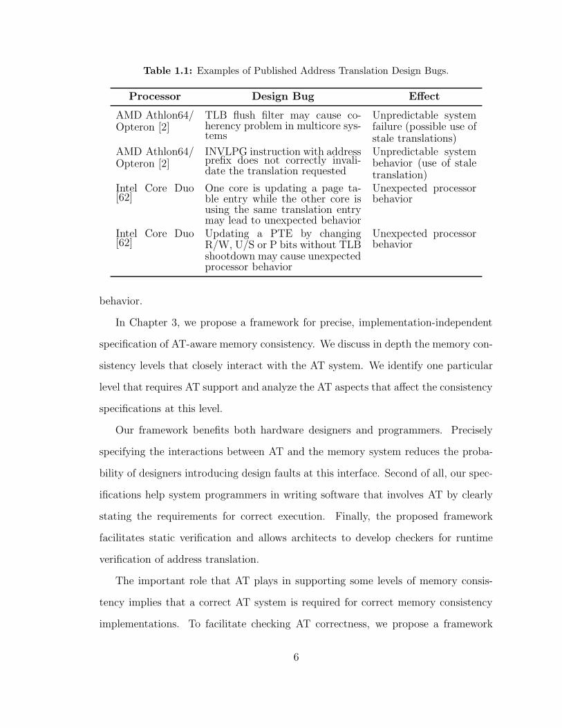
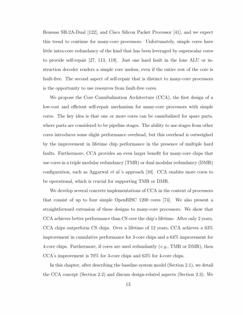
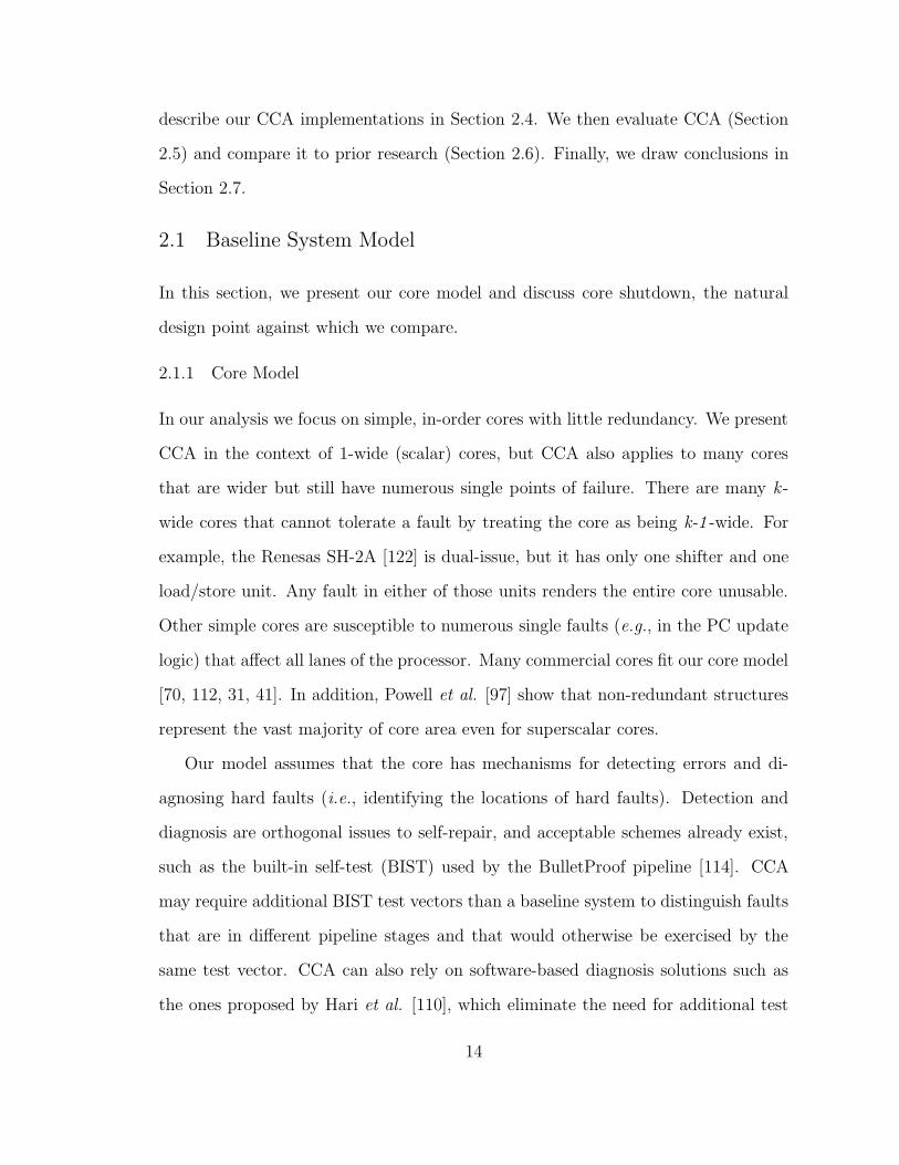
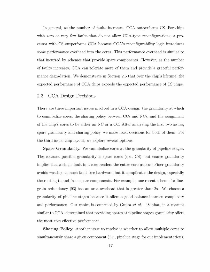
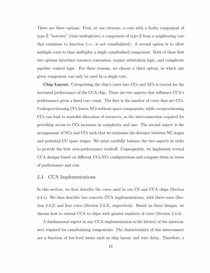
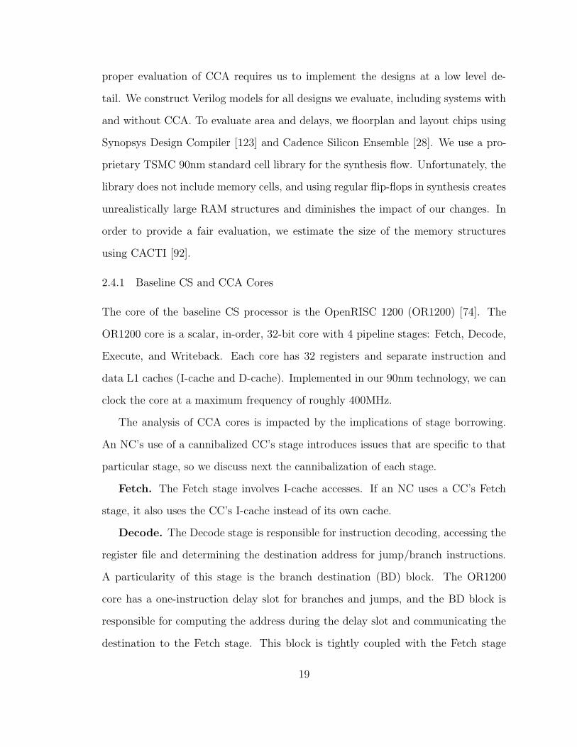
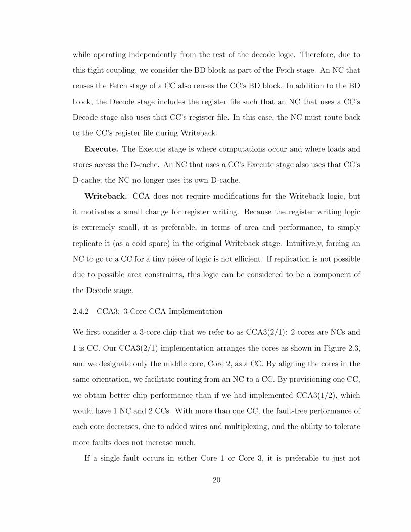
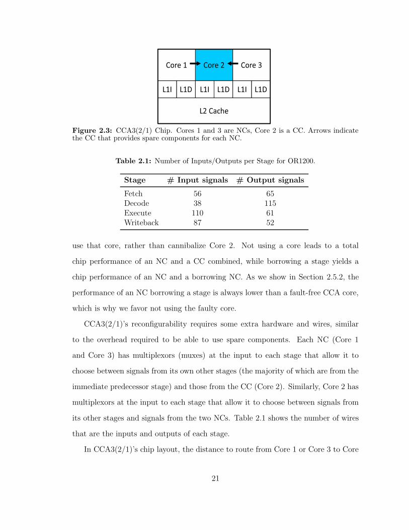
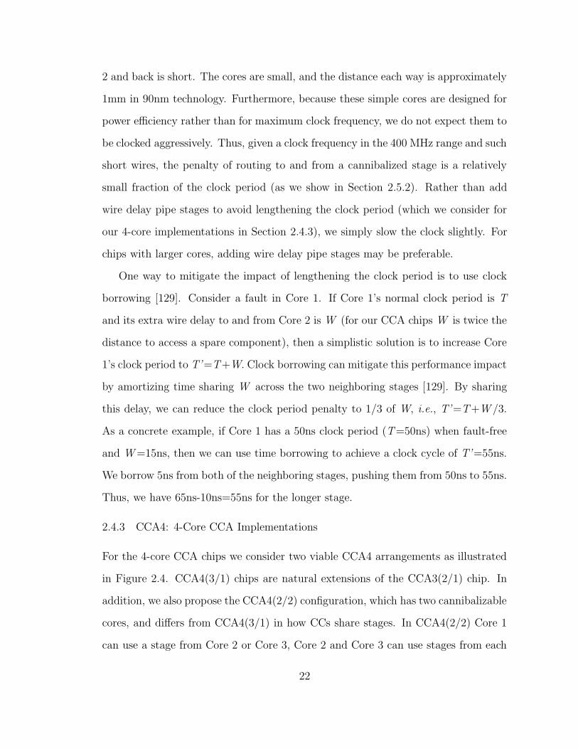
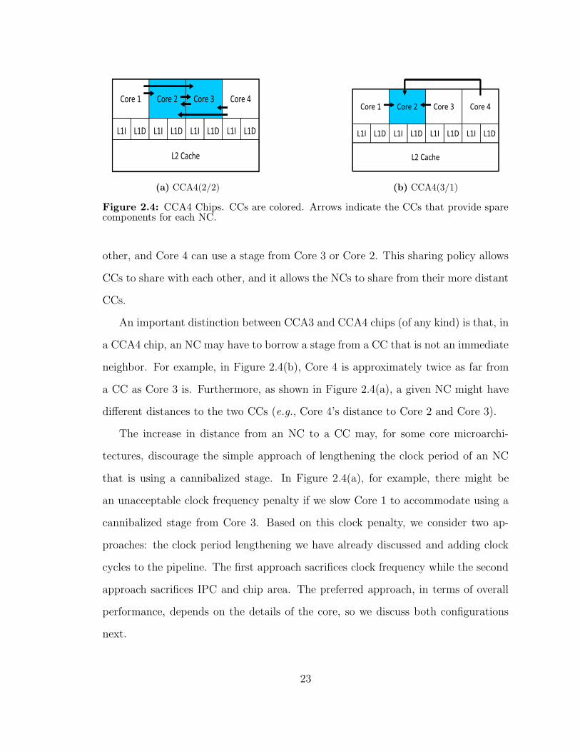
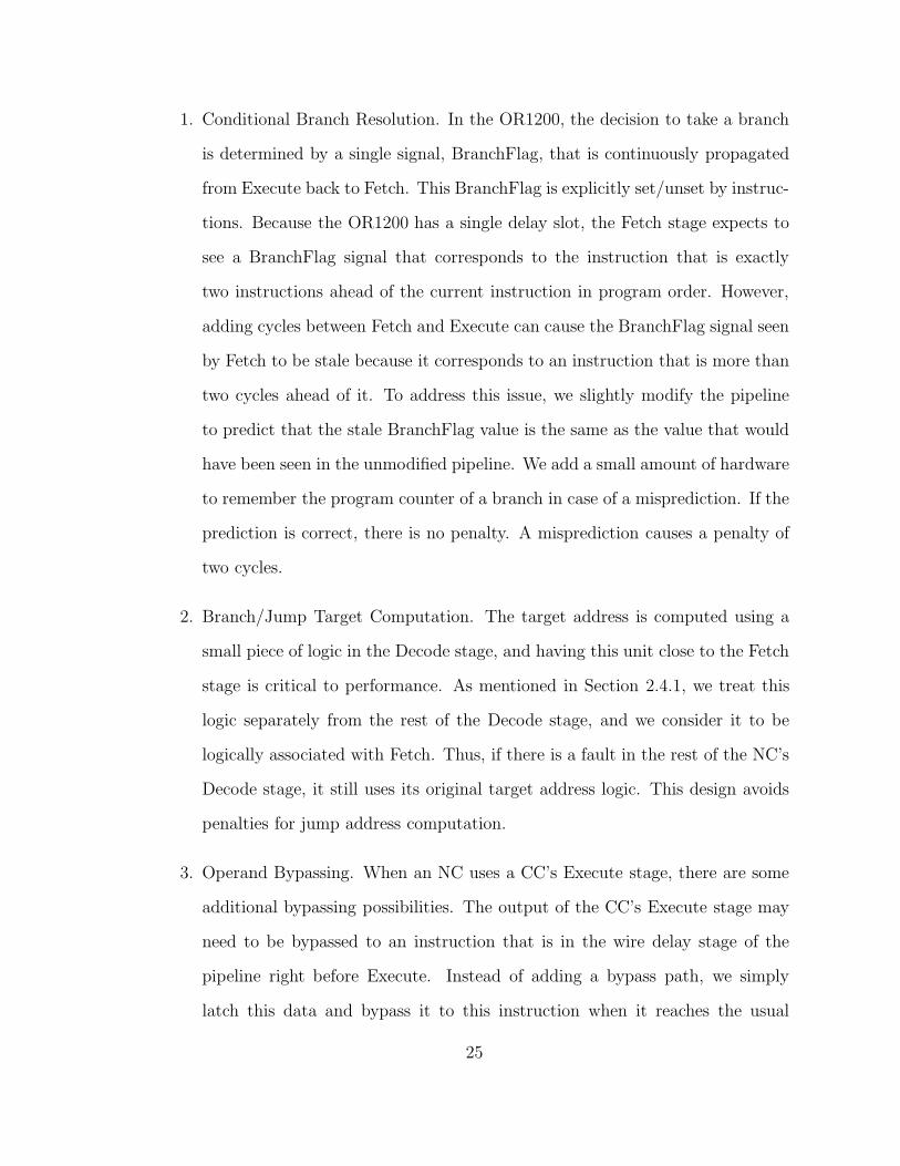
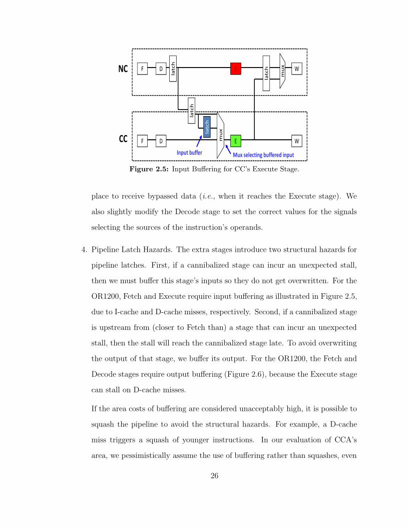
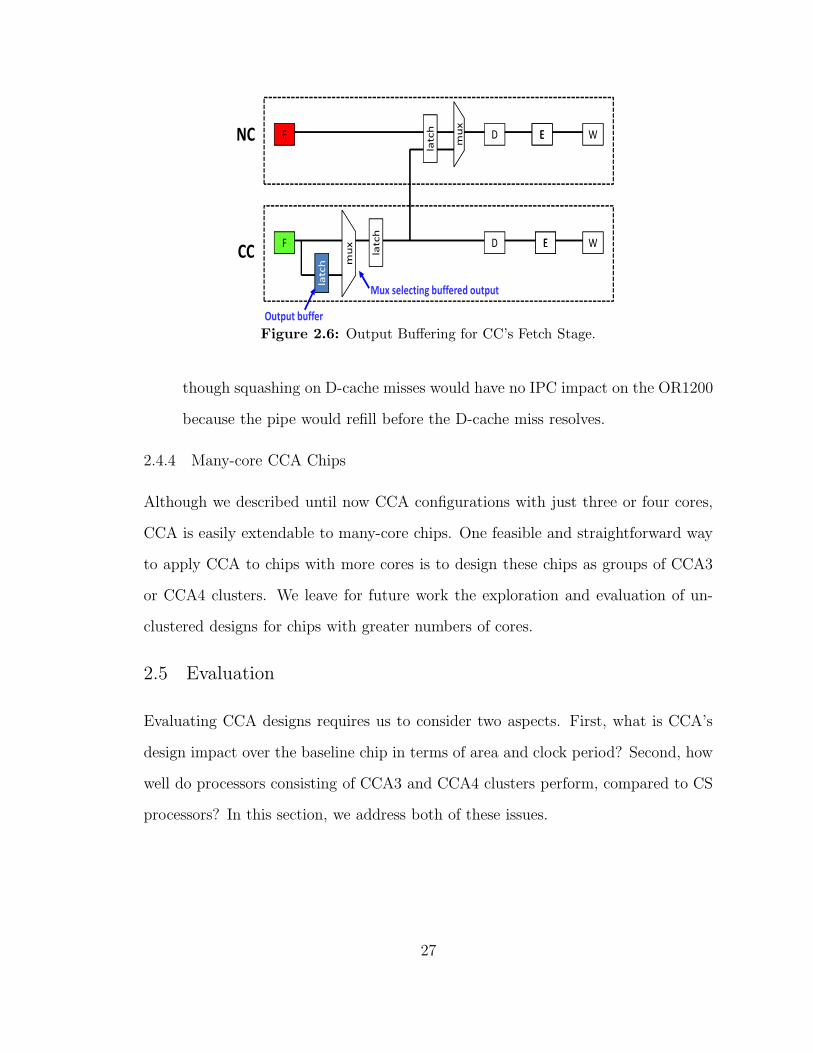
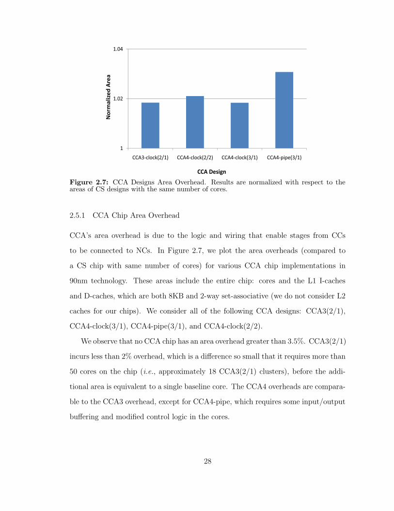
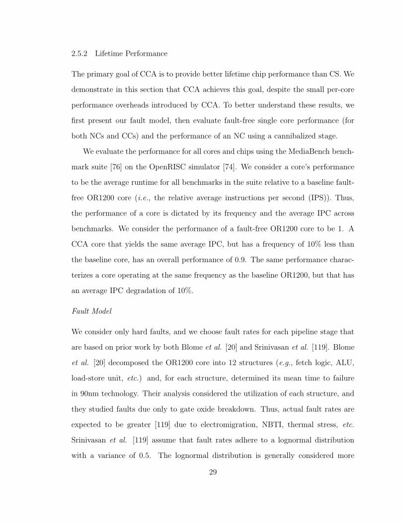
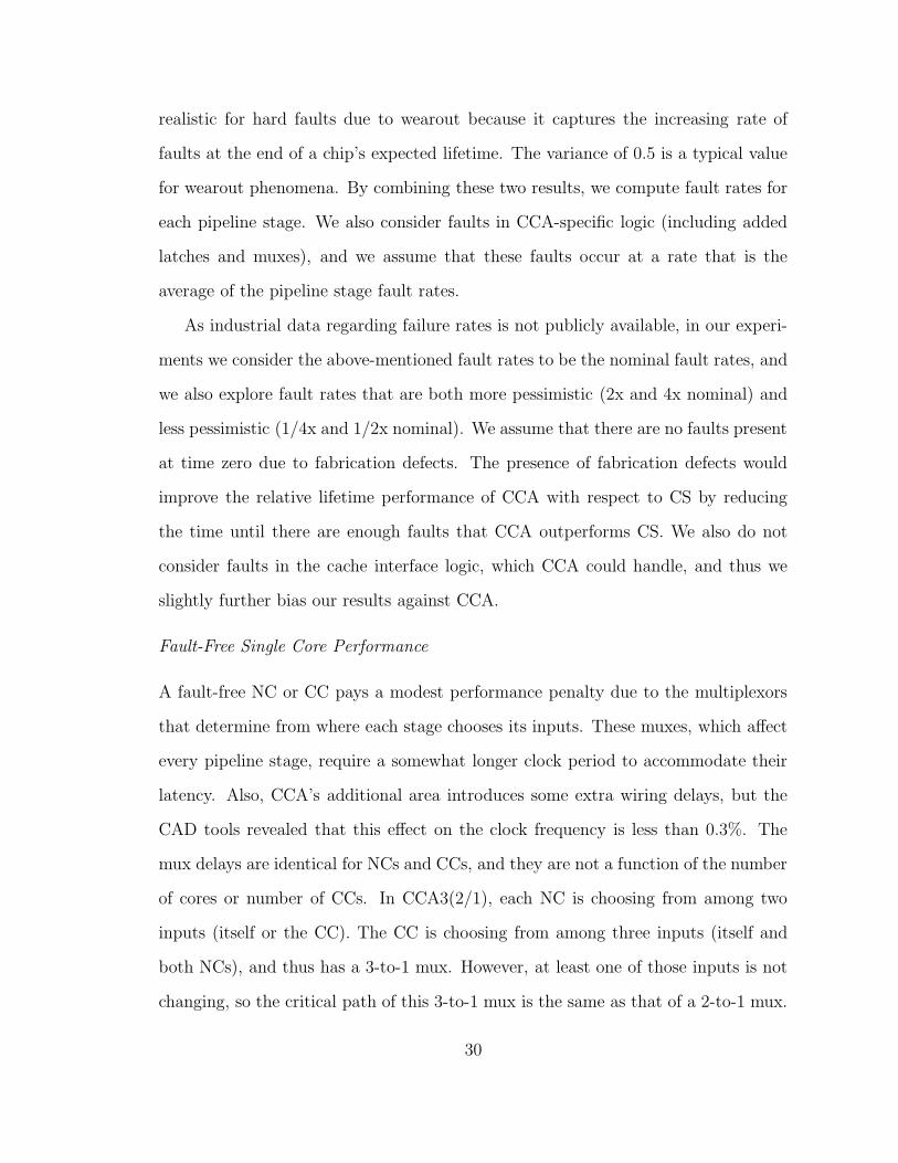
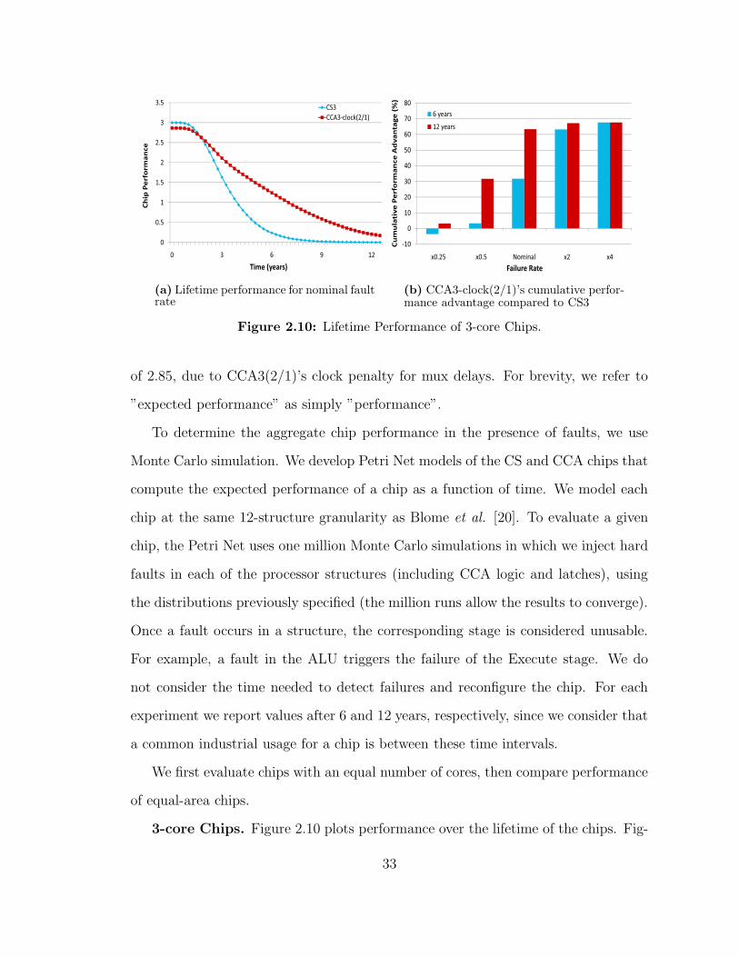
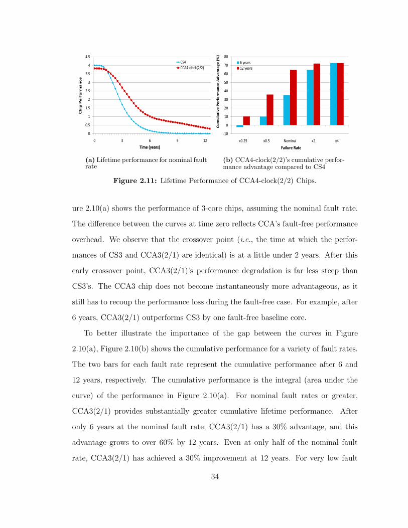
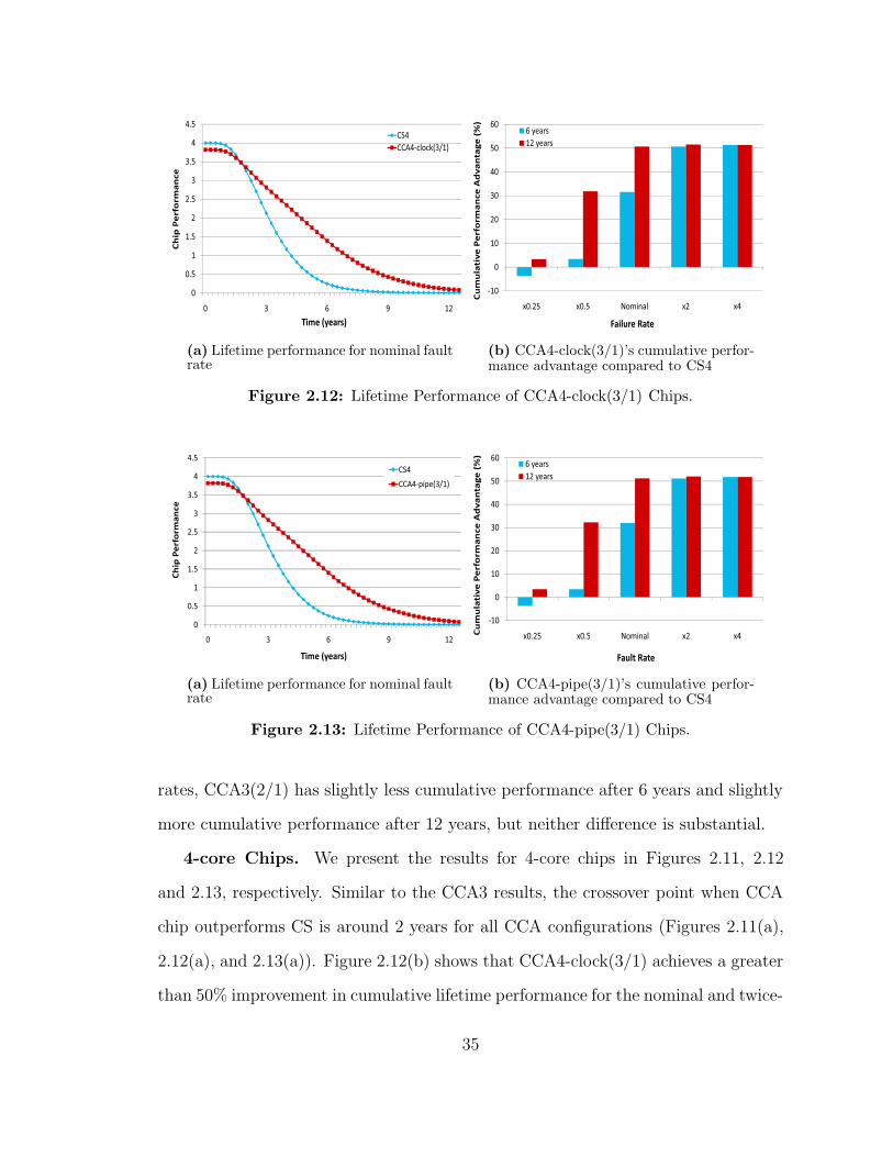
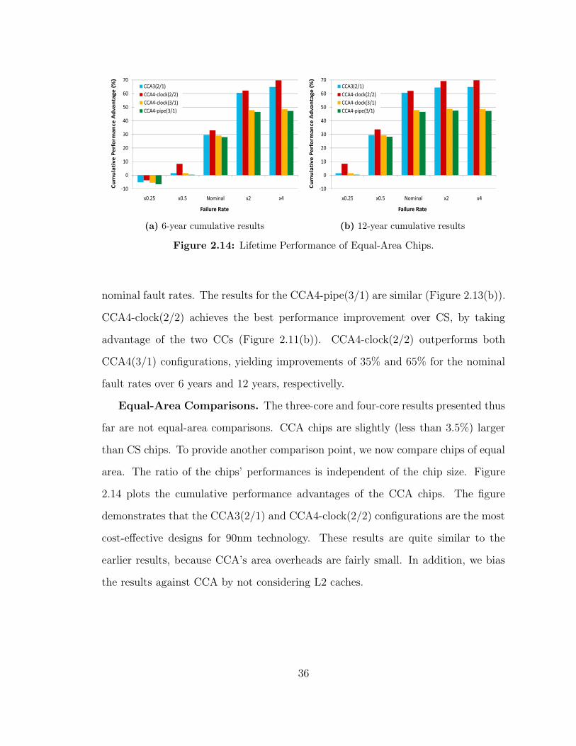
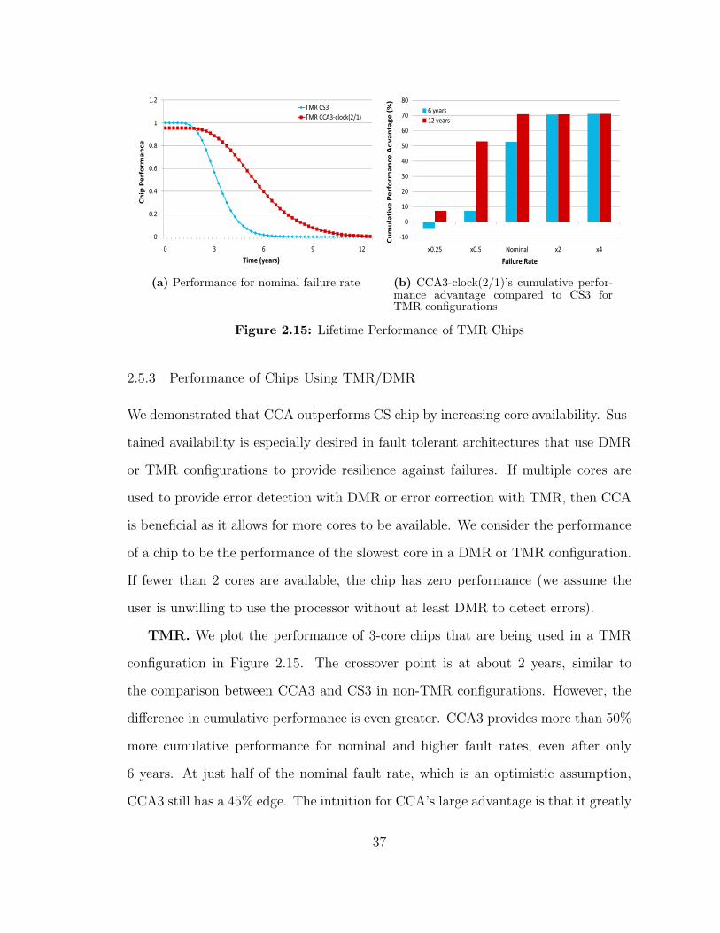
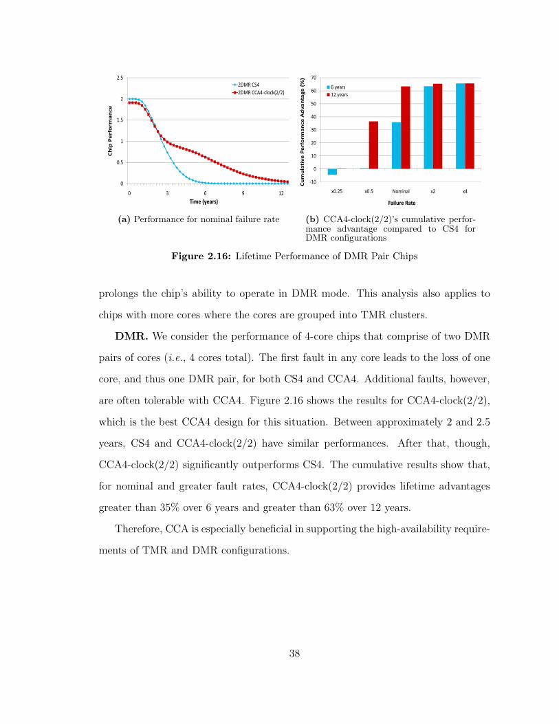
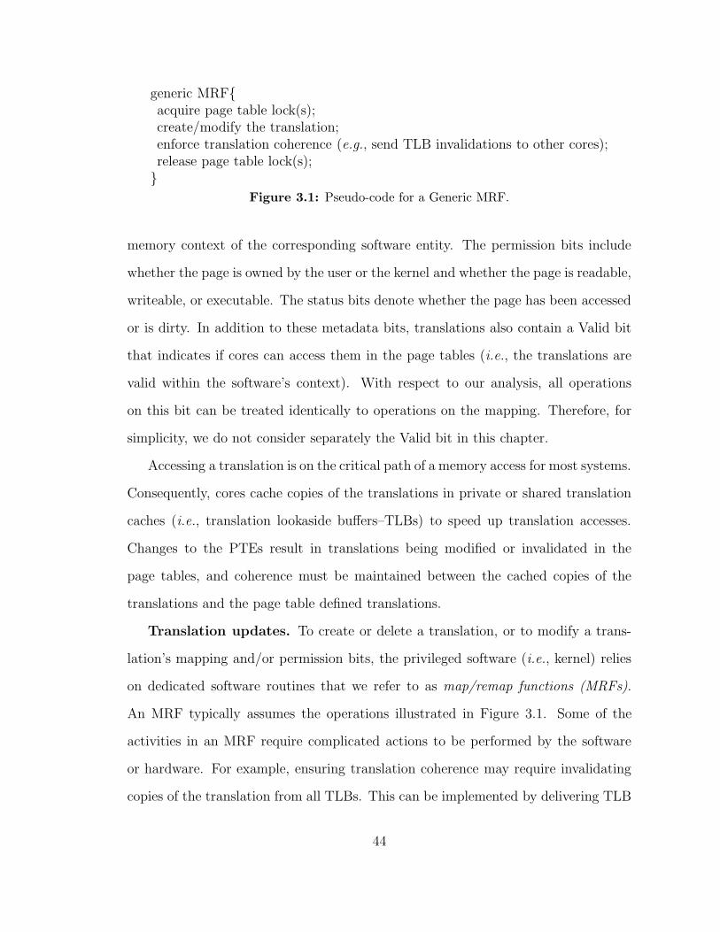
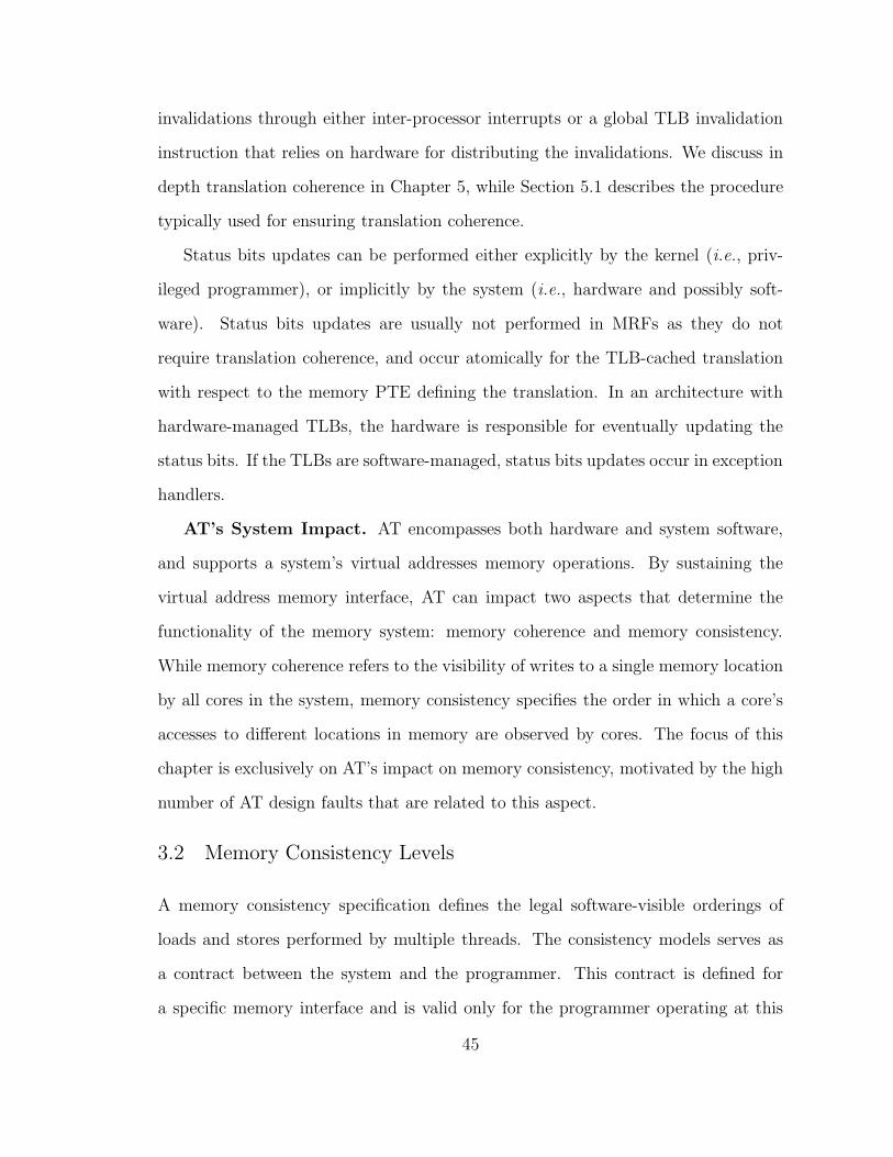
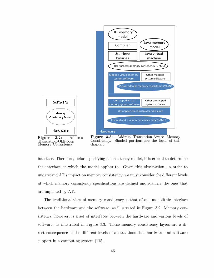
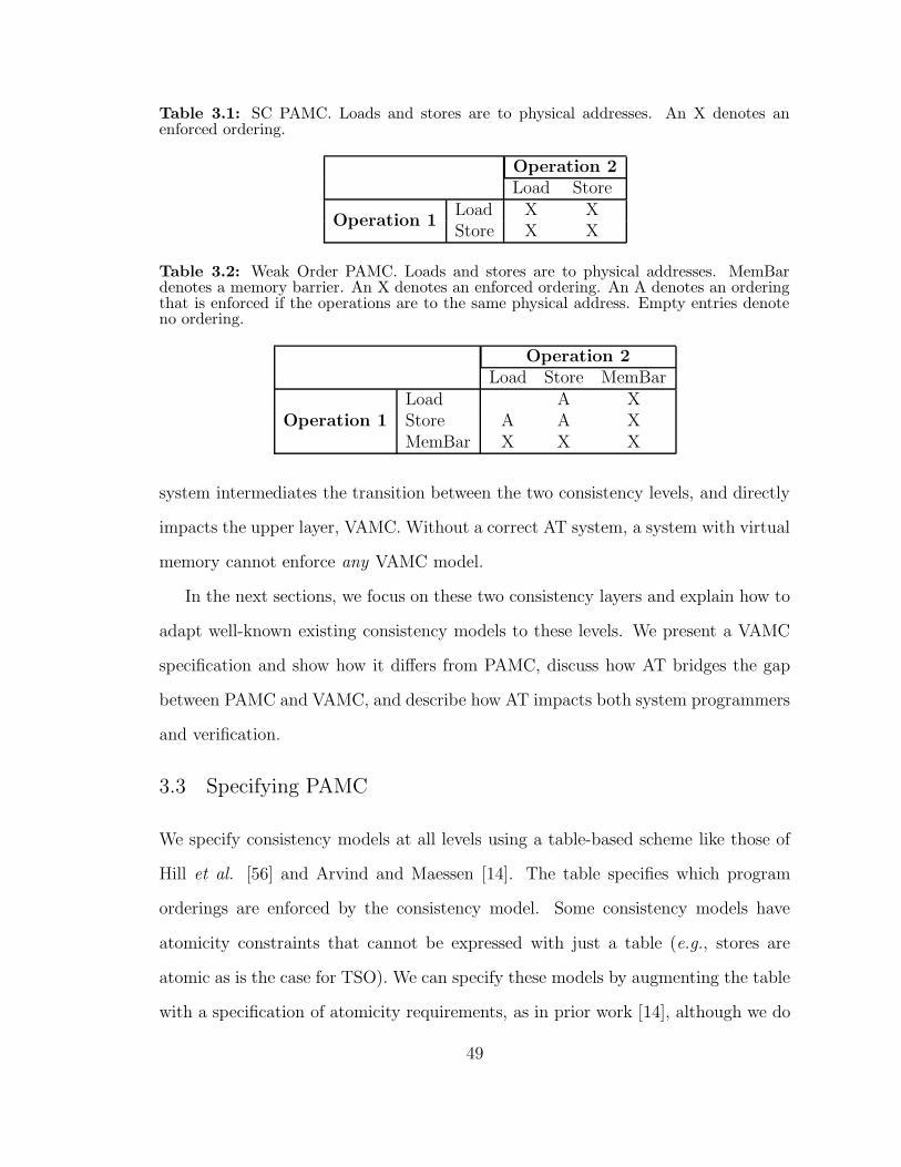
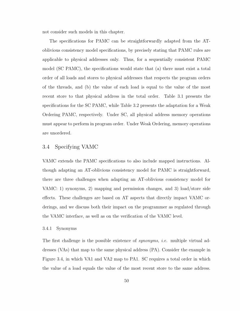
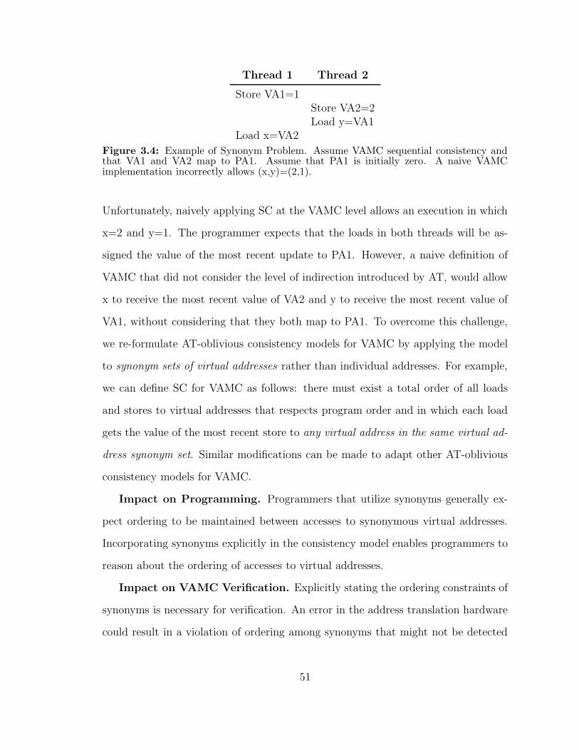
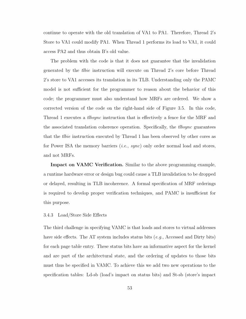
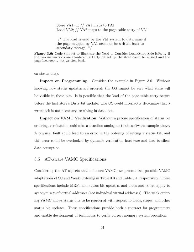
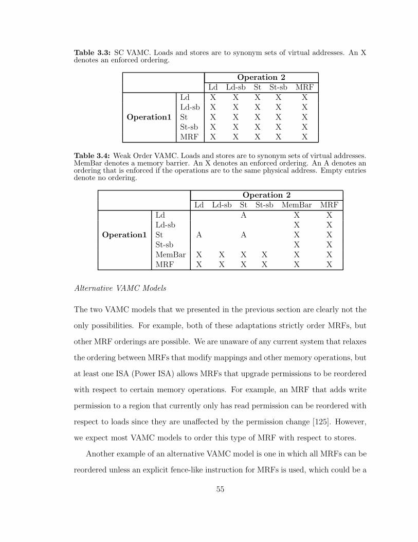
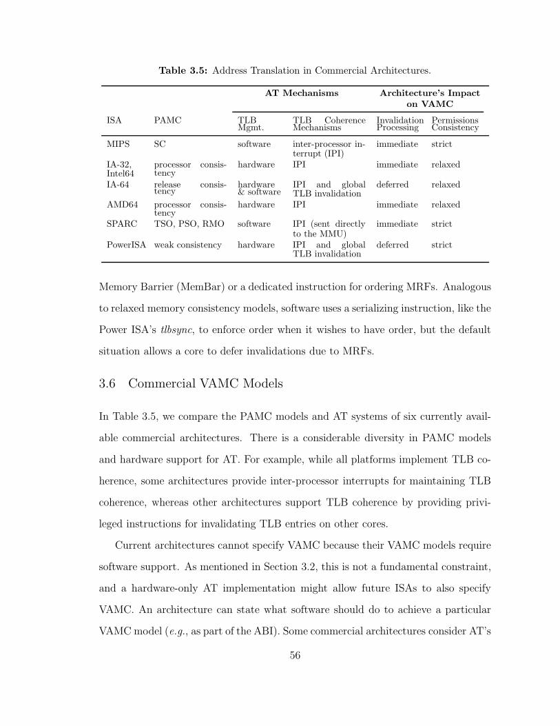
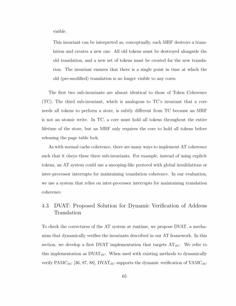
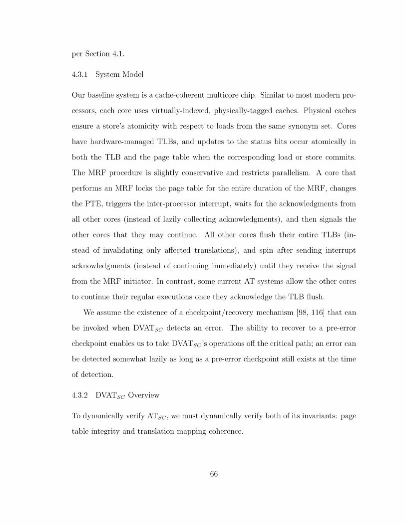
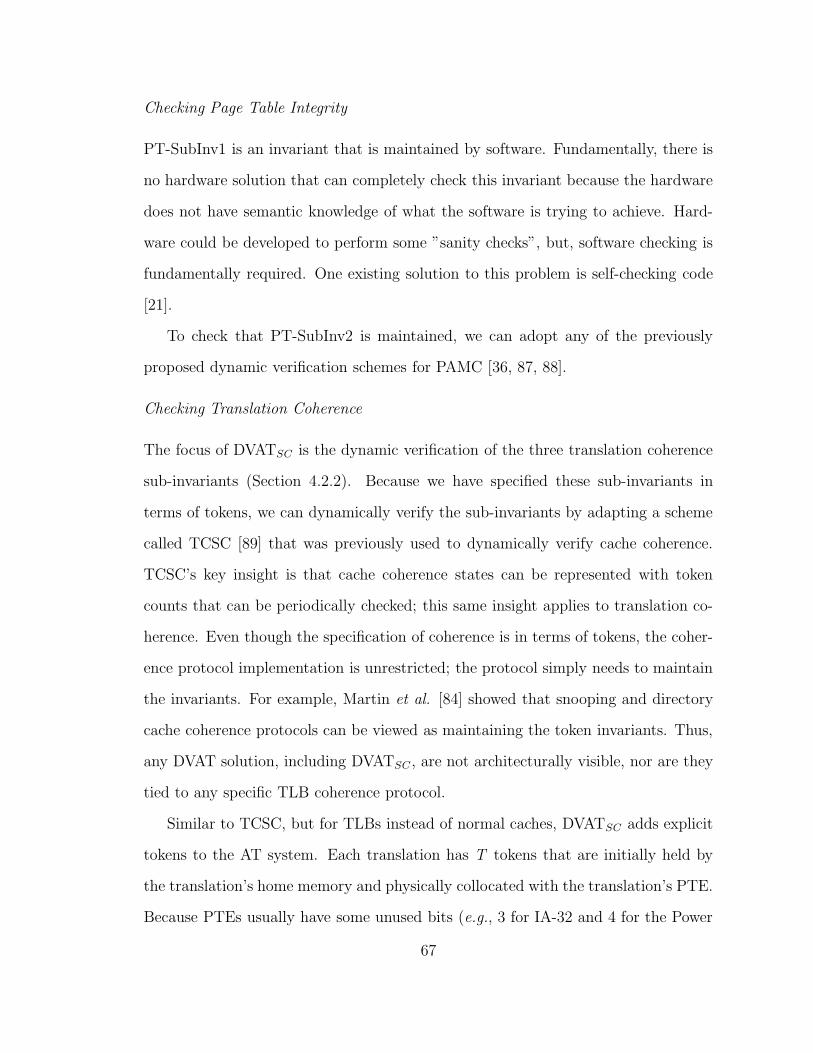
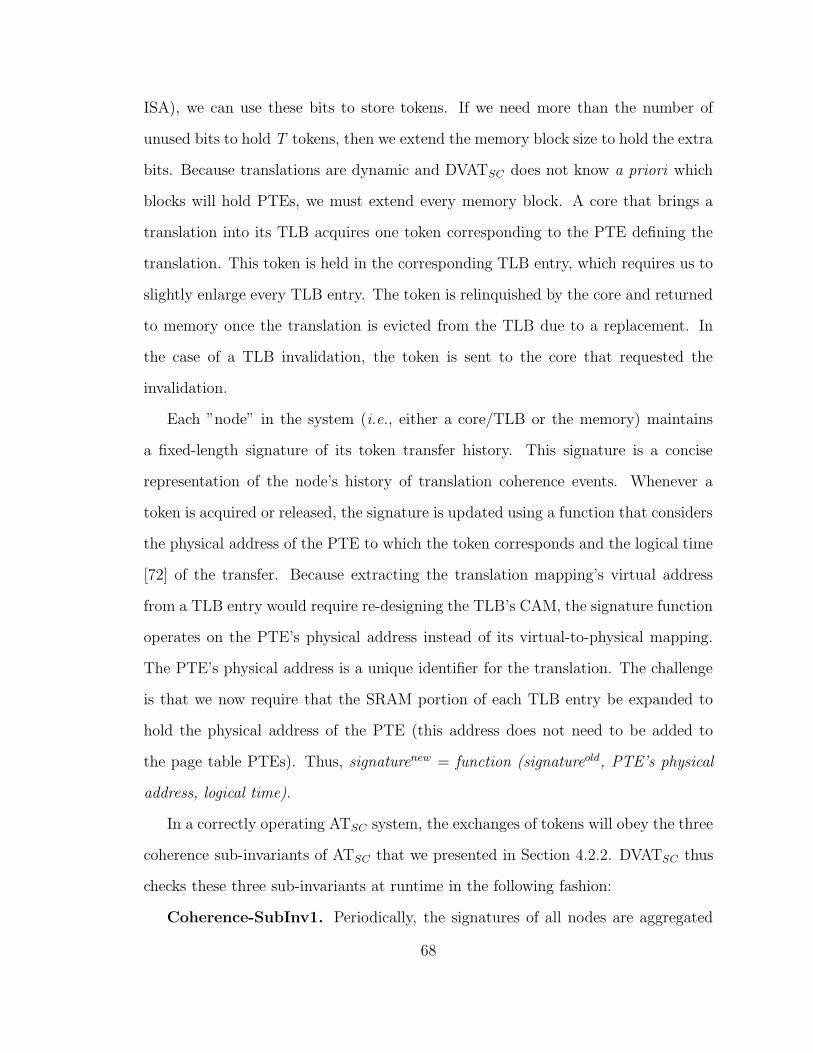
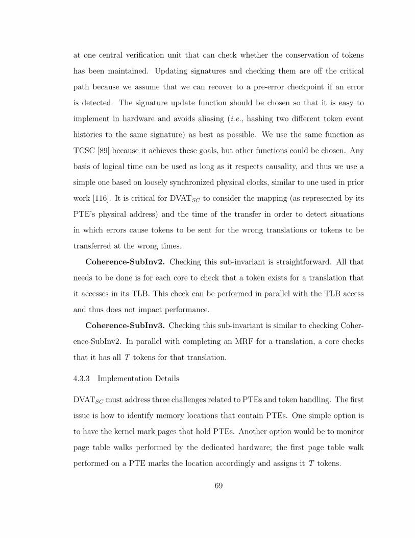
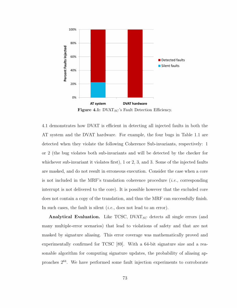
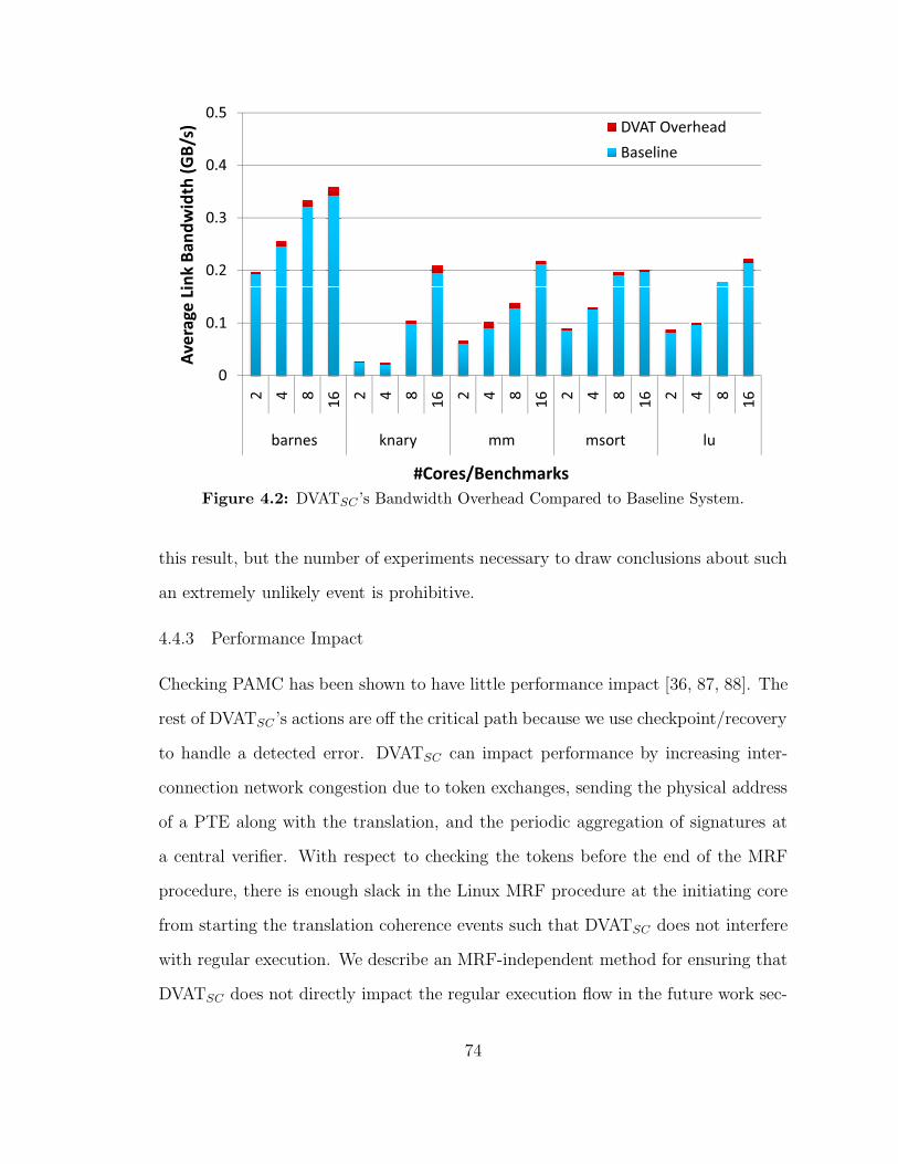
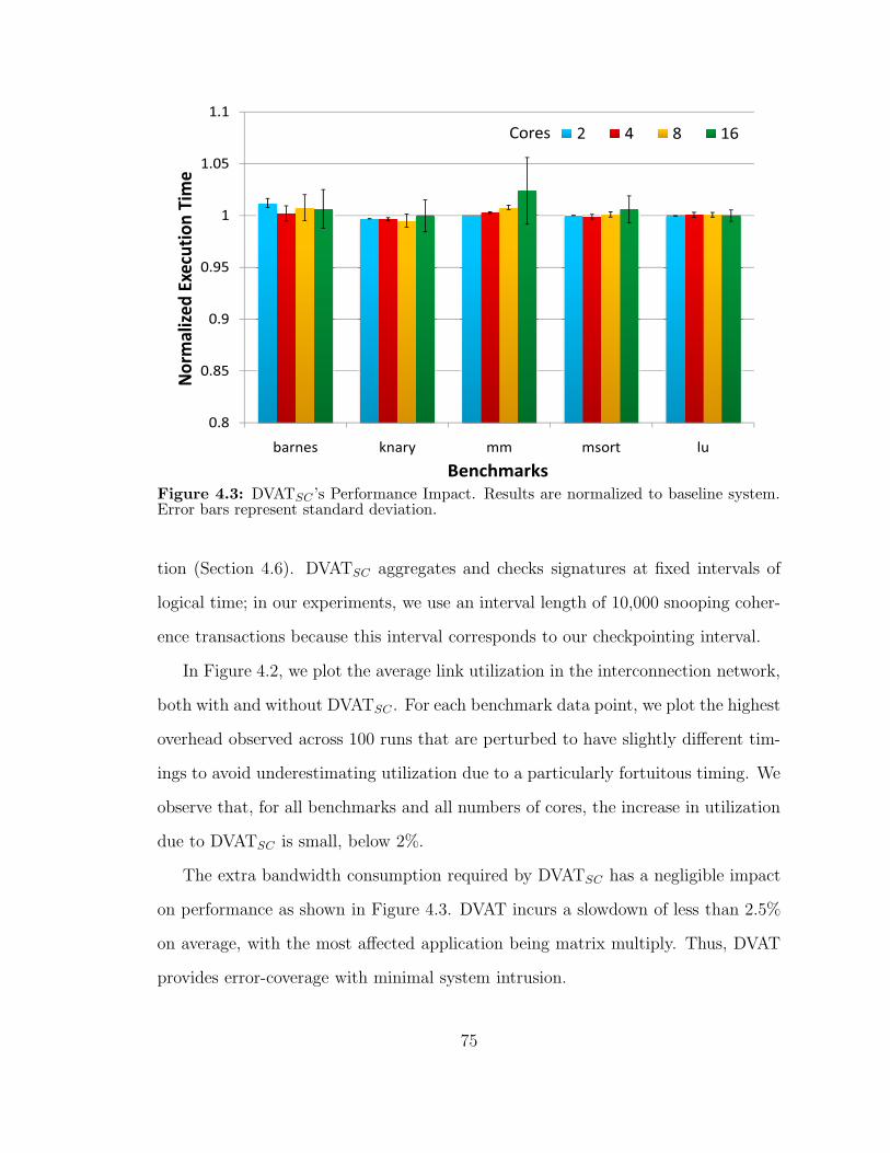
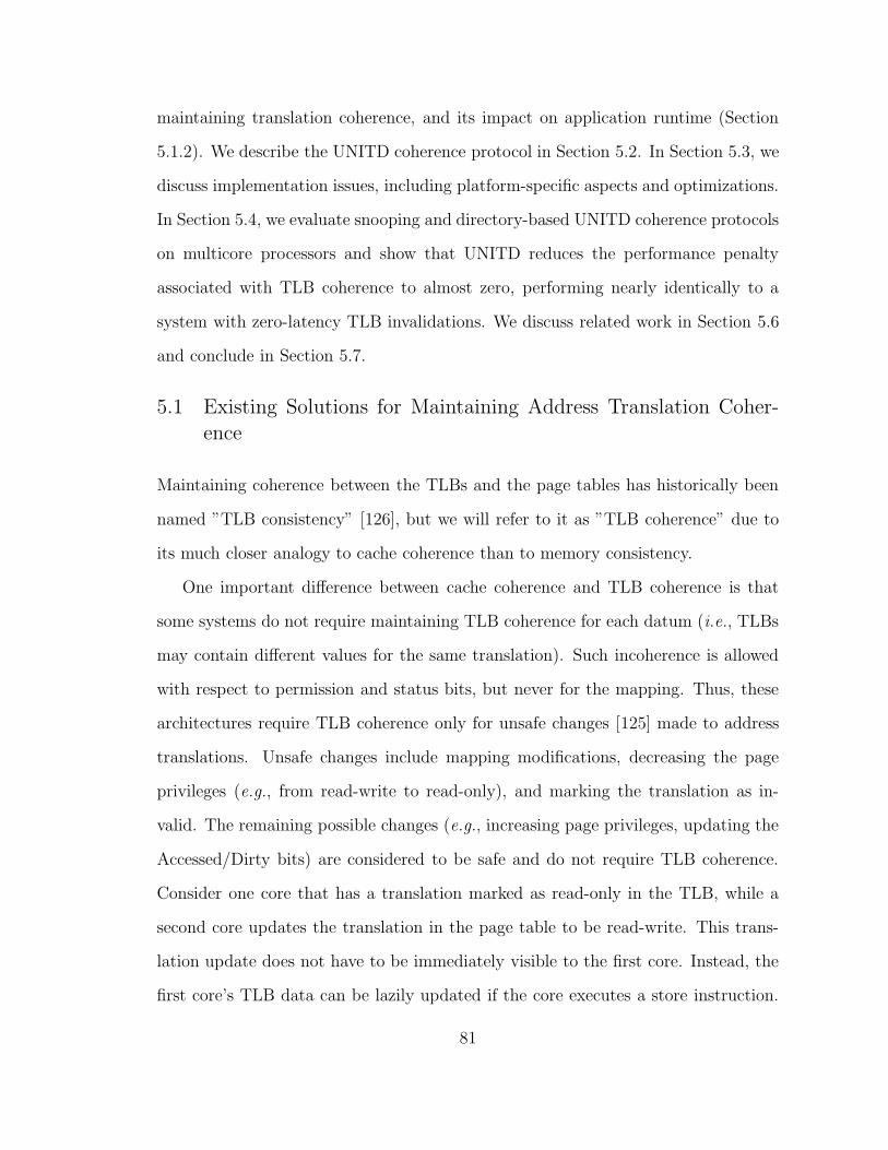
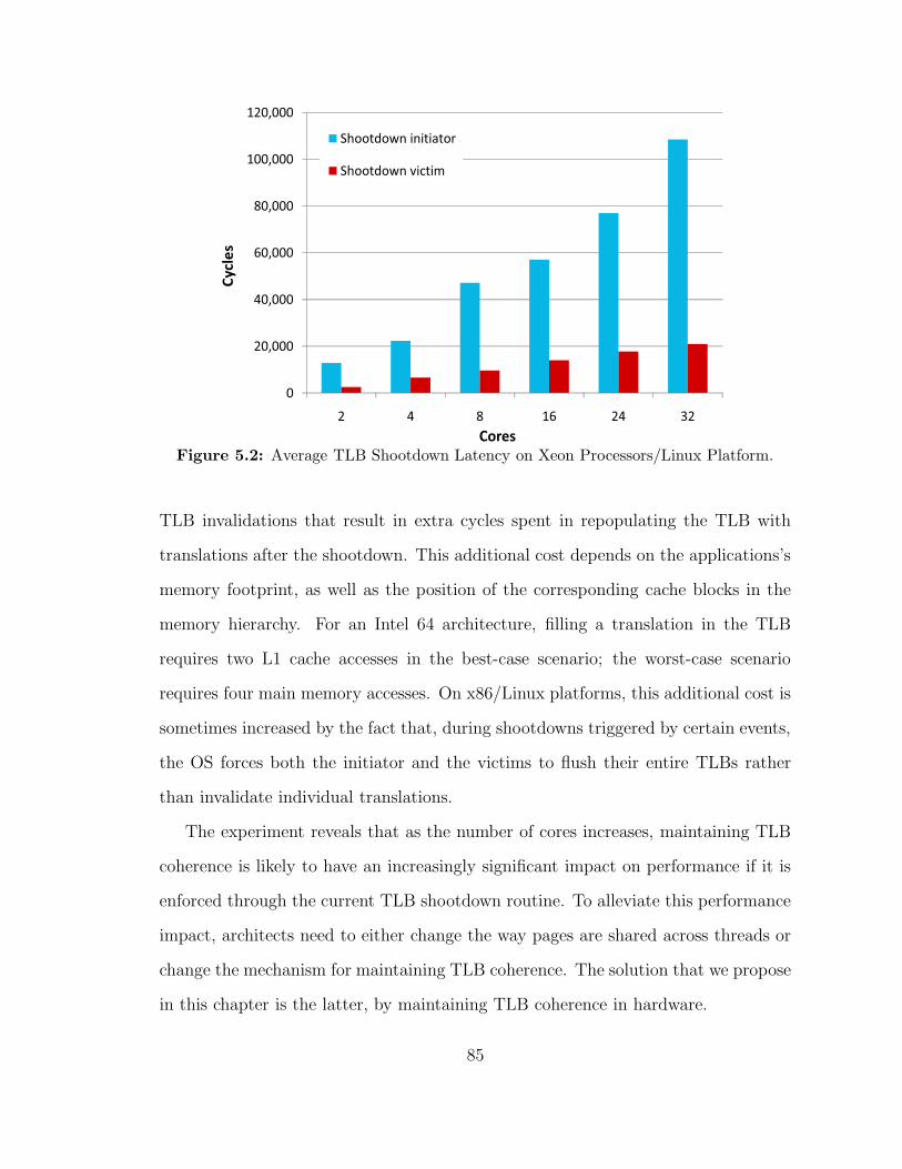
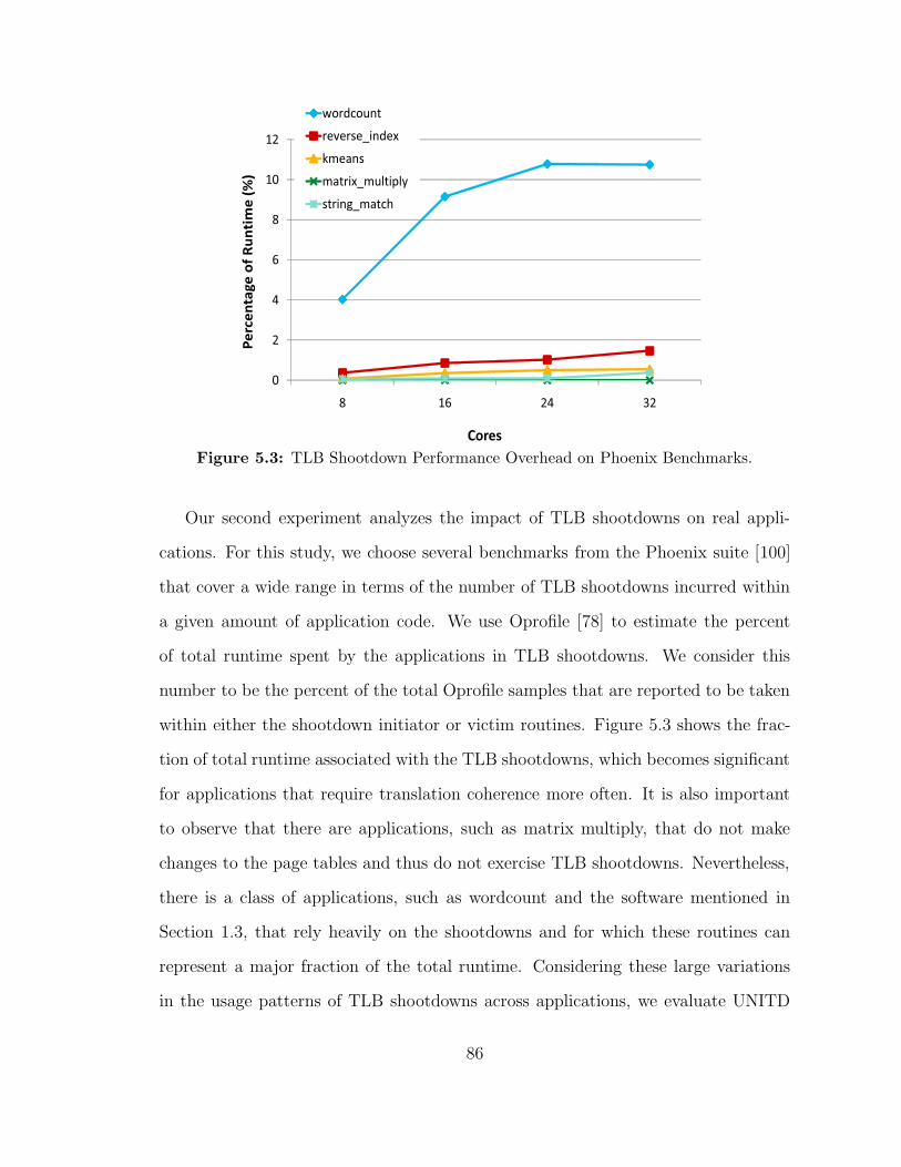
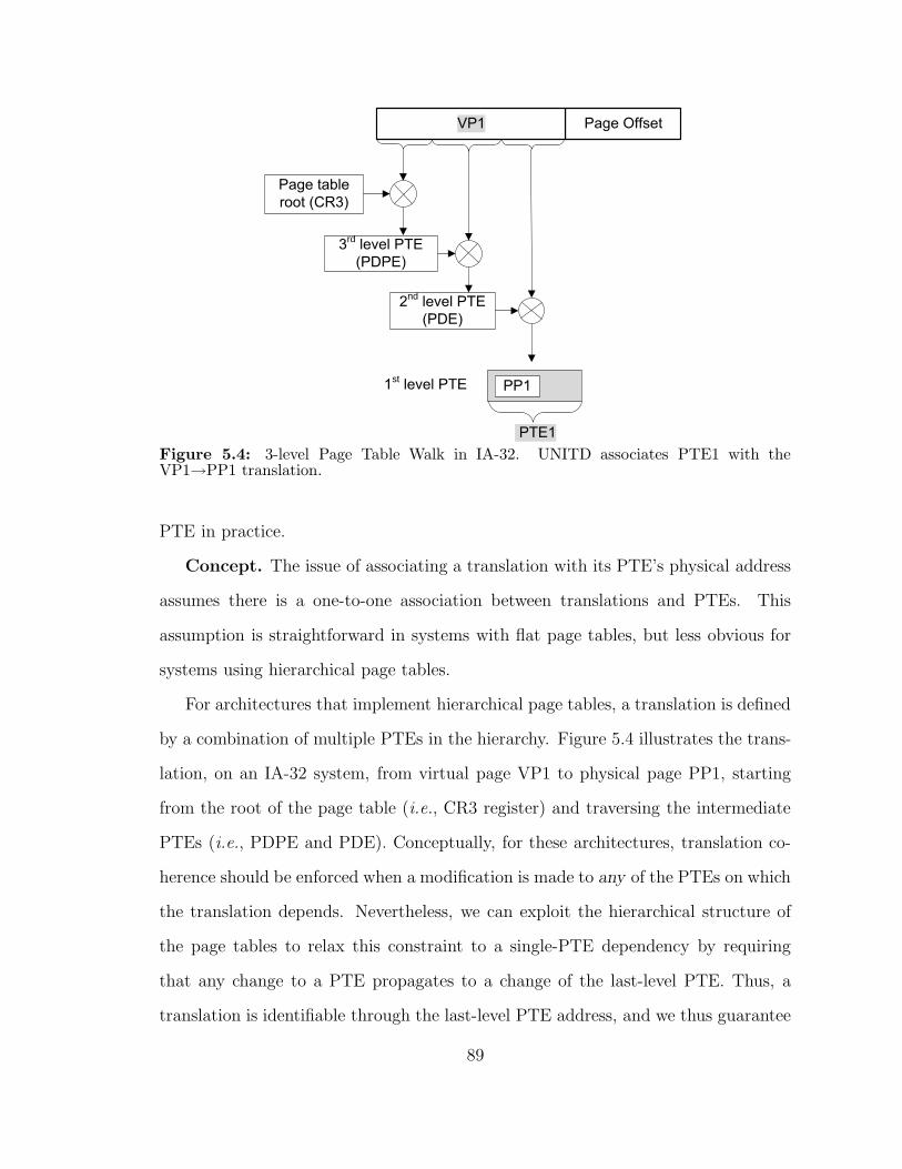
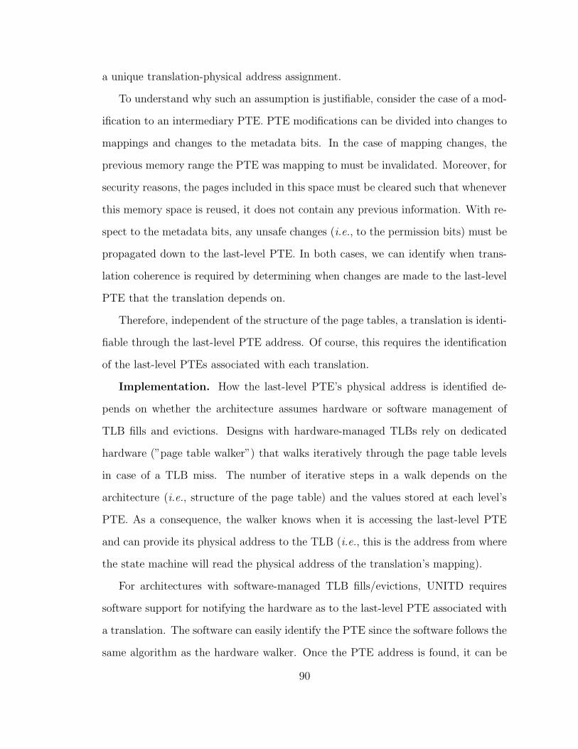
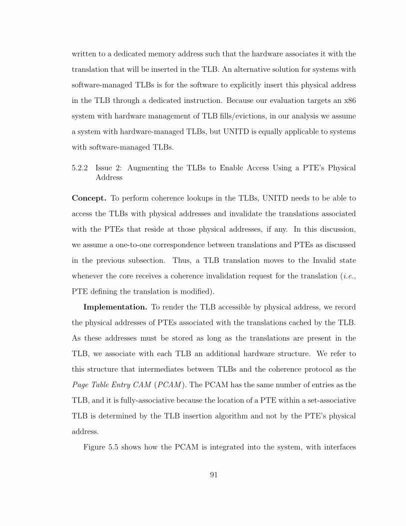
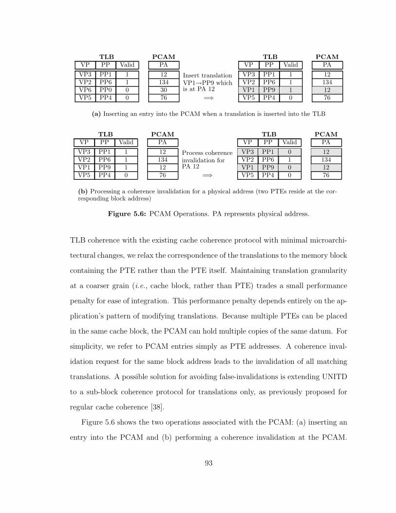
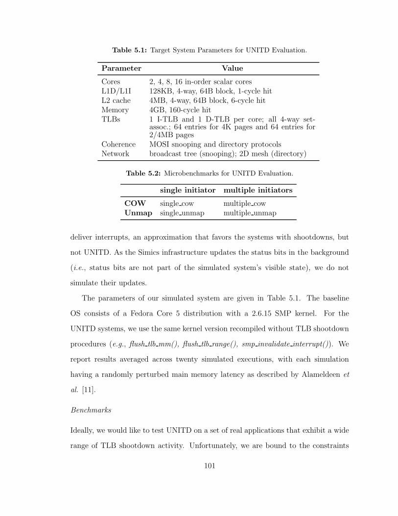
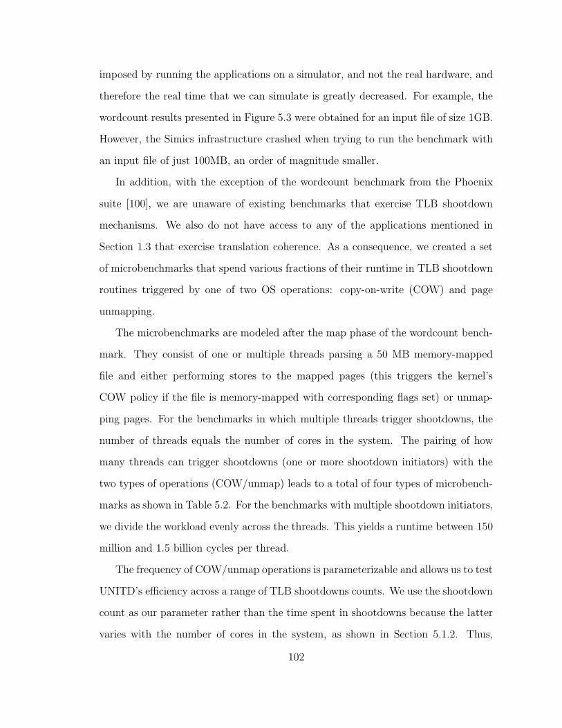
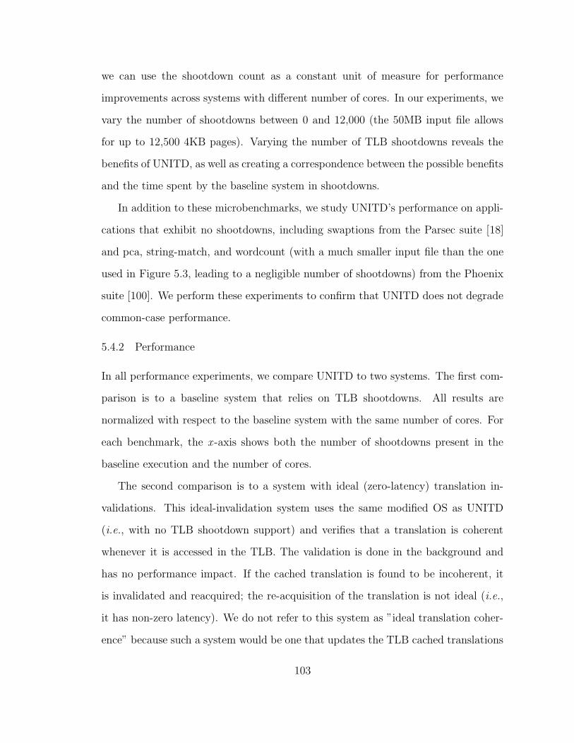
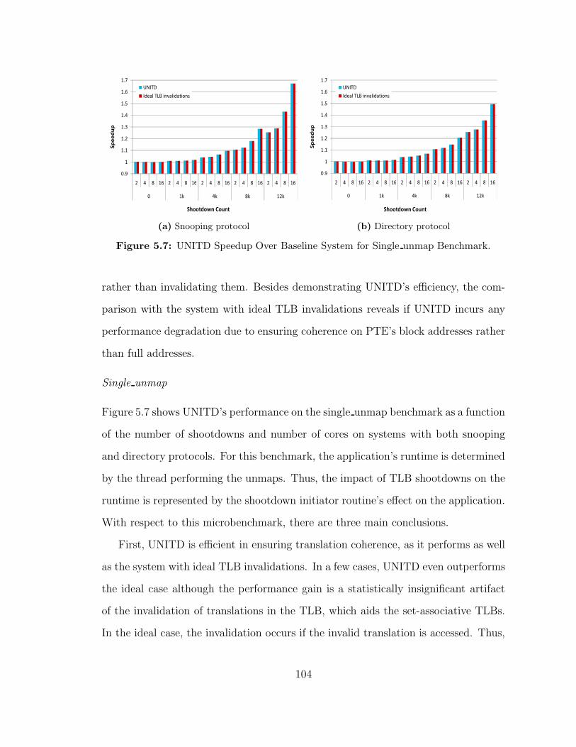
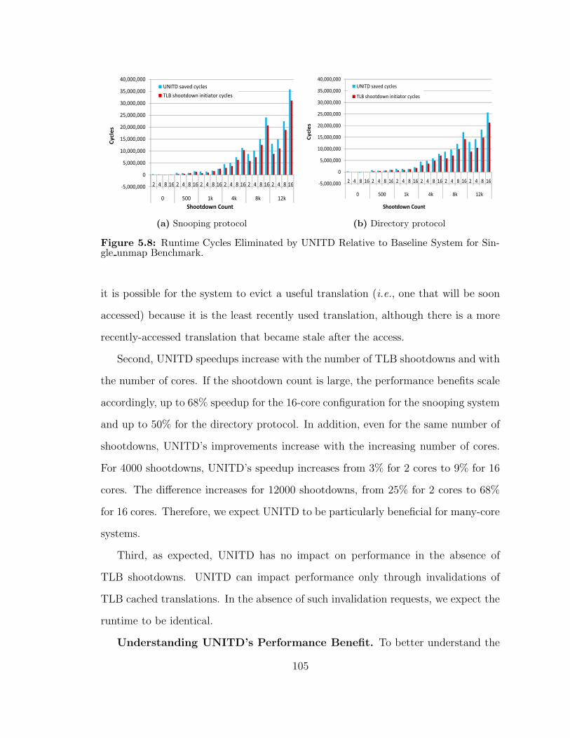
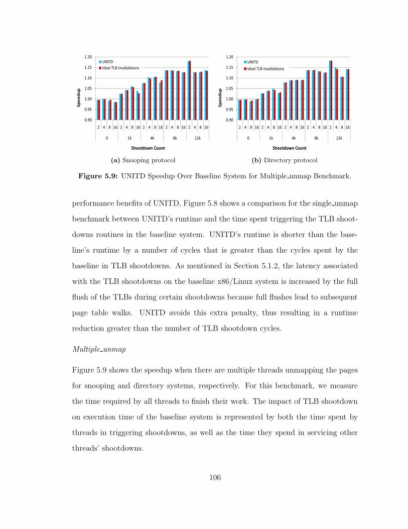
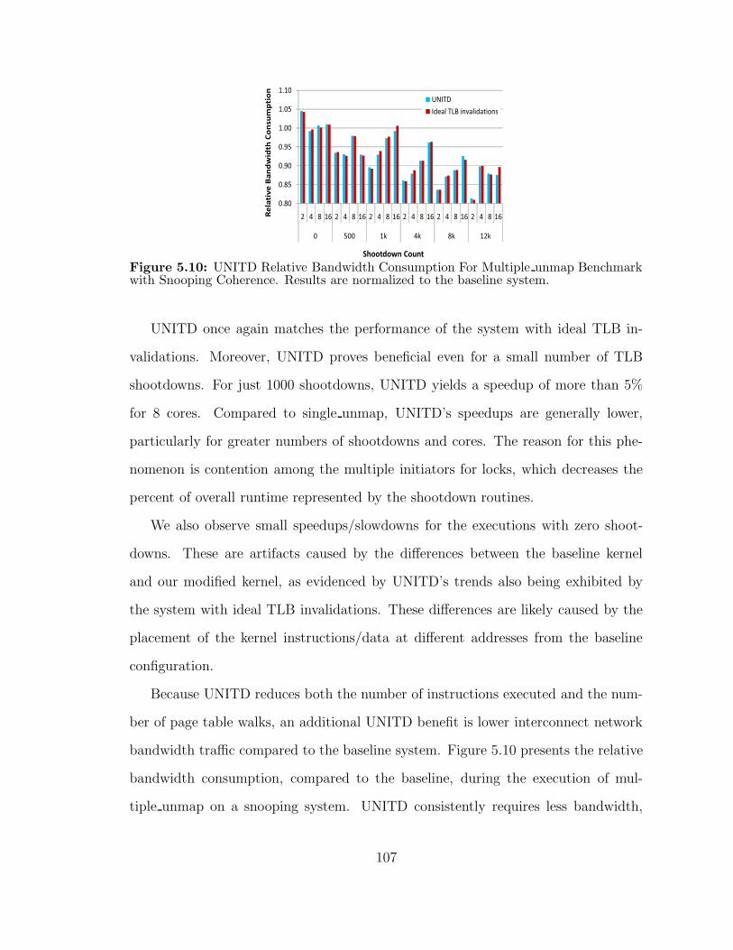
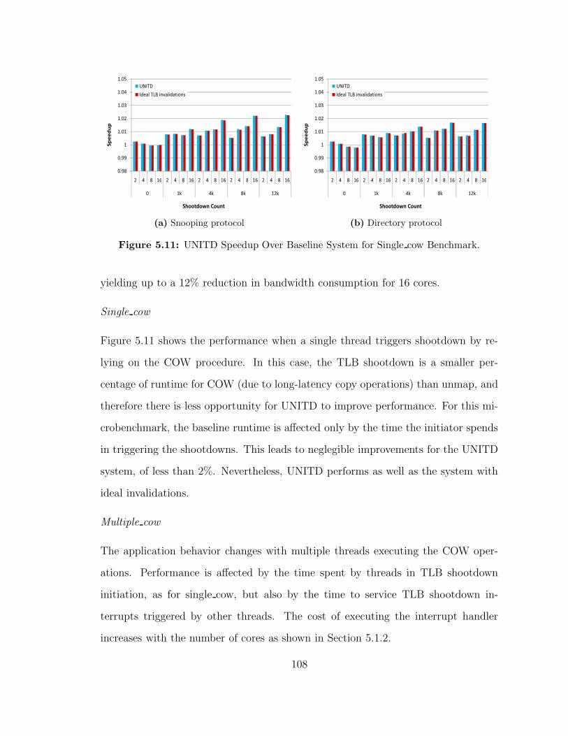
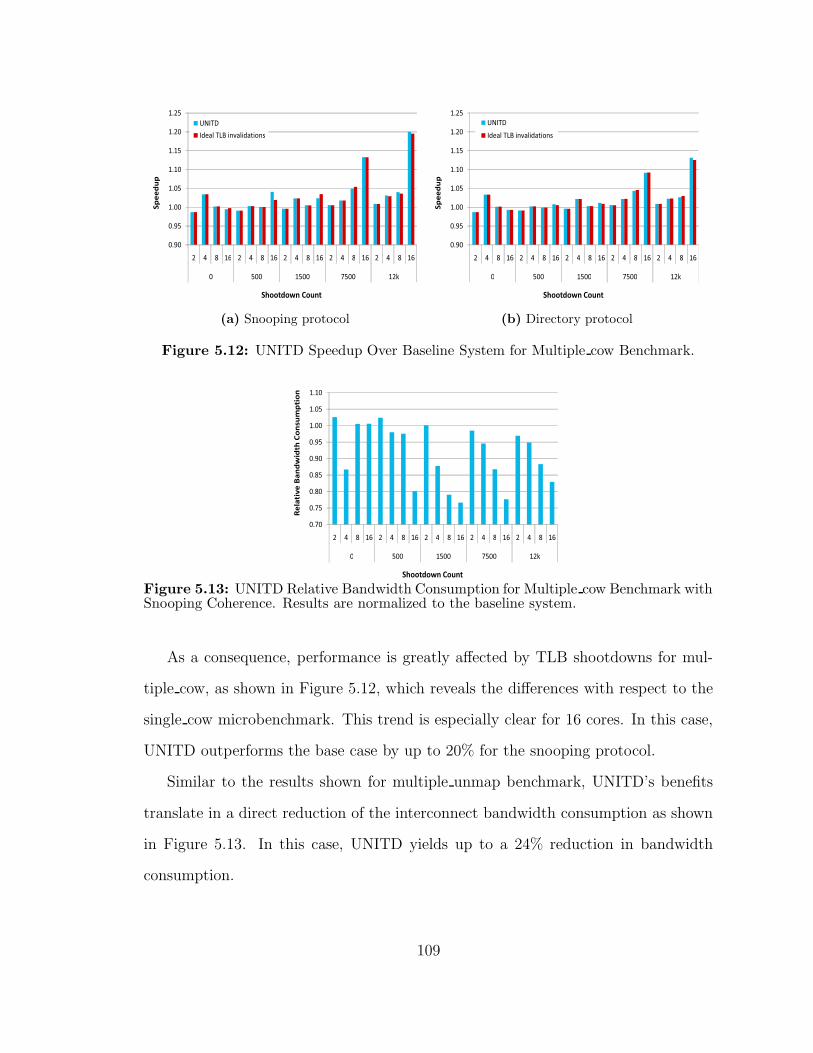
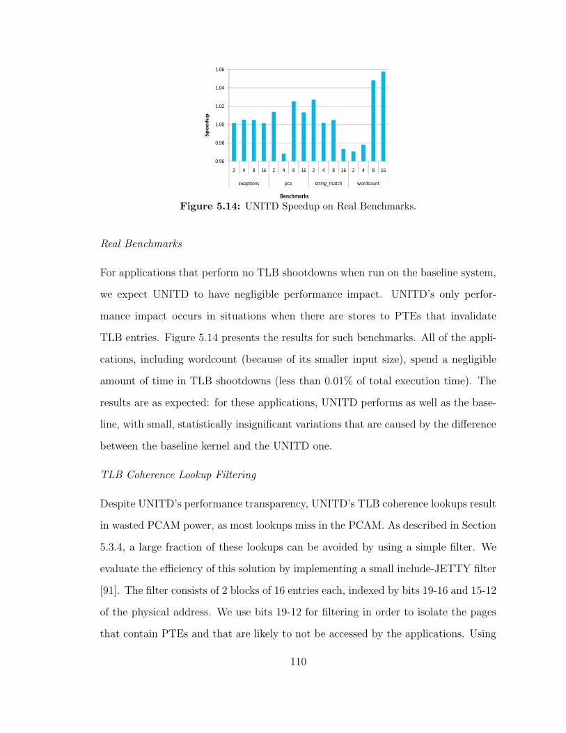
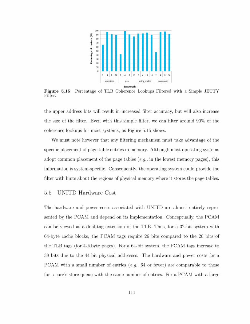
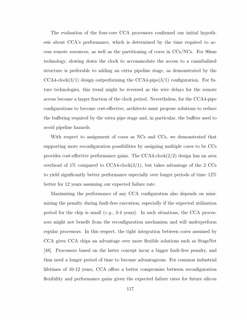
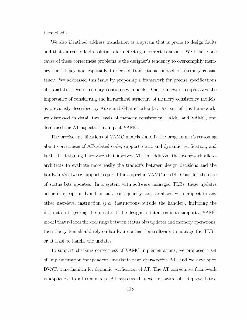
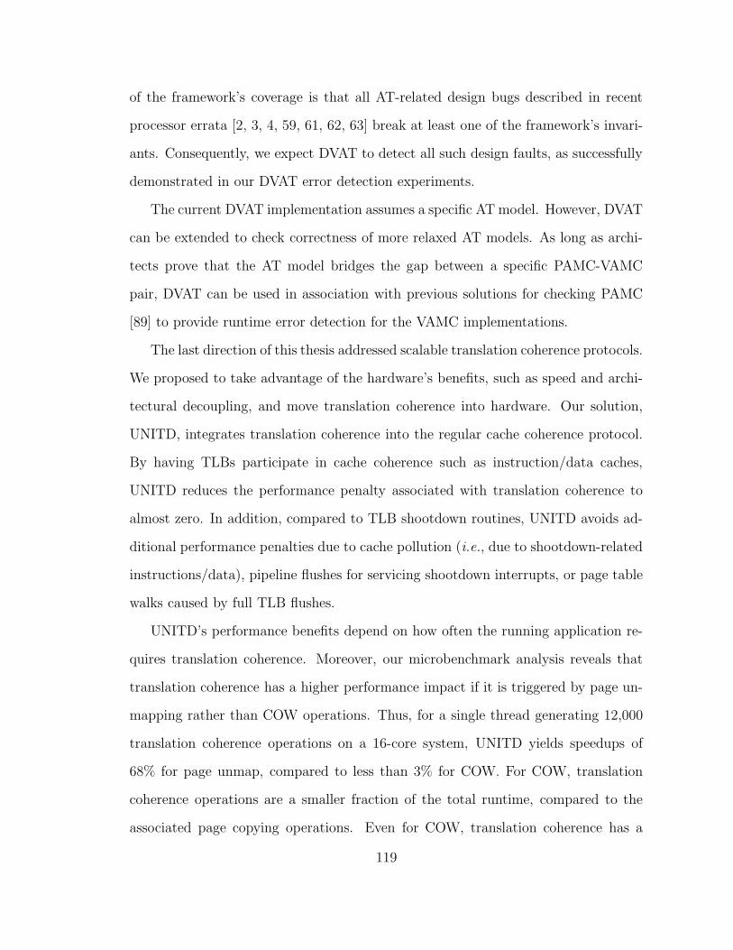
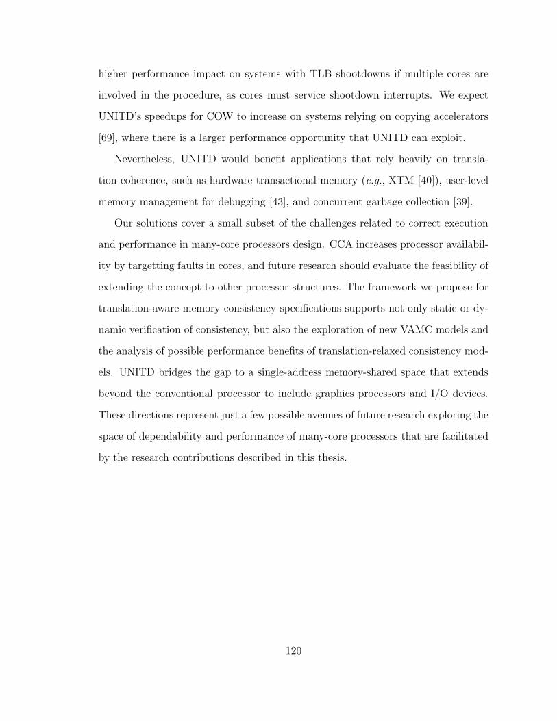


![E ective classi cation of algebraic structures. e ective ...amelniko/EffCtII.pdfvan der Waerden [45]. This e ective philosophy (called then \explicit procedures") can be found in early](https://img.pdfslide.net/doc/110x75/60a559526c545644d47fe8eb/e-ective-classi-cation-of-algebraic-structures-e-ective-amelnikoeffctiipdf.jpg)