Embed Size (px)
Citation preview

Portland State University
ME 493 Capstone Progress Report Spring 2016
Coturnix Quail Egg Embryo Extractor
(c-QEEE)
Sponsorship with
Child’s Cancer Therapy Development Institute
Industry Advisor
Dr. Charles Keller, M.D.
Faculty Advisor
Dr. Nathalie Neve, Ph.D.
Submit by
Alex Arnold, Joshua Lake, Robert Lesanovsky, Anne (Man Wai) Ng, Samuel
Rasmussen, Sam Sanford
June 3, 2016

Contents
Executive Summary 2
1 Introduction 3
2 Mission Statement 4
3 Product Design Specifications Summary 5
4 Top-level Final Design Alternatives 6
5 Final Design: Handheld Device 8
5.1 Suction Cups . . . . . . . . . . . . . . . . . . . . . . . . . . . . . . . . . . . . . . . . 8
5.2 Vacuum Pump . . . . . . . . . . . . . . . . . . . . . . . . . . . . . . . . . . . . . . . 9
5.3 Puncturing Device . . . . . . . . . . . . . . . . . . . . . . . . . . . . . . . . . . . . . 9
5.4 Mechanical Levers . . . . . . . . . . . . . . . . . . . . . . . . . . . . . . . . . . . . . 10
6 Final Design Evaluation 11
6.1 Performance& . . . . . . . . . . . . . . . . . . . . . . . . . . . . . . . . . . . . . . . . 11
6.2 Structural Integrity . . . . . . . . . . . . . . . . . . . . . . . . . . . . . . . . . . . . . 12
6.3 Manufacturability & Assembly . . . . . . . . . . . . . . . . . . . . . . . . . . . . . . 12
7 Conclusion 14
Appendix A: Bio-safety Criteria 15
Appendix B: External Research Summary 17
Appendix C: Internal Research Summary 18
Appendix D: Detailed Product Design Specifications 19
Appendix E: CAD Drawings 21
Appendix F: Bill of Materials 26
Appendix G: Operational Manual 27
1

Executive Summary
The Children’s Cancer Therapy Development Institute researches developmental biology
and oncology of cancers in children. Their goal is to develop and prove new treatments for stopping
metastasis of cancers in children. They conduct their experiments on fertilized coturnix quail egg
embryos. The current method of removing the embryo from the egg shell is difficult and time
consuming, the project is to build a device that can transfer the contents of a quail egg to a six
well dish faster than the current rate of one per minute, with a higher success rate than the current
50% and without contaminating the contents. Dr. Charles Keller is the internal customer for this
project and will significantly influence the design requirements. The researchers and interns are the
external customers and they will help determine more specific design elements. We conducted a
survey of the customers to determine and prioritize the design elements.
The documentation requirements for this project are a Product Design Specifications doc-
ument, a progress report, and a final report. Currently the project is in the phase of finalizing
the product to the end user. During external research, existing products and patents related to
separating the egg shell from its internal contents are identified. External research also consists of
researching in embryology of avian species in order to understand how to safely extract the contents
of the egg. Internal research are conducted on two major features: a safe method to puncture the
egg shell and an optimal suction cup design that is capable of holding the egg shell under applied
tension. During the design evaluation phase, suction cups are concluded to be the most acceptable
choice in terms of egg shell separation. The detailed design phase focuses on designing the handheld
device, which consists of four major components: the mechanical lever, two suction cups, puncturing
mechanisms, and a vacuum system. The working prototype is delivered the end users.
2
1 Introduction
The mission of the Children’s Cancer Therapy Development Institute is to translate sci-
entific discovery into clinical trials by understanding and proving new disease-specific treatment
options for children with cancer [1]. Currently, the researchers are exploiting assays to stop metas-
tasis by experimenting on fertilized coturnix quail egg embryos. The accessible embryo of the avian
species yields as an ideal and convenient model for studies in developmental biology and oncology.
It offers easy manipulation and visualization by simply removing portions of the eggshell [2].
In the Children’s Cancer Therapy Development Institute laboratory, the experimentation
employs fertilized quail eggs that have been incubated for 72 hours. Prior to the extraction process,
the slide warmer is set at approximately 37�C, along with wire cutters and a solution of 70% EtOH
prepared.The forceps are sanitized with the EtOH solution and wiped with kimwipes before each
extraction. The initial procedure of the removal implementation method consists of placing the
incubated eggs into the slide warmer with the narrower ends of the egg down for ten minutes, this
allows the yolk to move to the top of the egg. In addition, one of the co-culture well plates is placed
inside the slide warmer.
After the preparation, the egg is held slightly above the empty well plate while keeping
it upright at a tilted angle. The forceps are then used to puncture the shell and cut around the
circumference of the egg until the shell fragment is removed (the shell is slightly pinched in the
process). The entire contents of the egg are poured into the well with the embryo intact. The
successful extraction and survival of the embryo is based on the visibility of the beating heart
facing upward and the yolk sac intact. The procedure is concluded with each plate labeled with the
non-viable embryos covered and marked with an ‘X’. The plates are then placed into the embryo
incubator at 37.4�C with 0% of carbon dioxide.
The traditional method is time-consuming, and it yields low embryo survival rates. Our
role in the cancer research project is to implement an efficient and safe process to extract all the
content of the quail egg without any cross-contamination and damages to the embryo. The new
methodology will improve the efficiency and success rate of embryos from the current implementation
process.
3

2 Mission Statement
The objective of this project is to design and fabricate an efficient method (ideally a device)
that will safely extract the contents of a fertilized quail egg, and place the contents into a separate
dish with the heart of the embryo being accessible to the researchers. Throughout the process, the
apparatus cannot damage or contaminate the embryo. The time for the apparatus to extract the
contents of the egg should be shorter than the current extraction period employed by the researchers
(approximately one egg per minute). A functioning prototype with a high success rate (e.g. higher
than the current implementation method of 50%) will be delivered in June 2016. A high performance
device will help improve the metastasis experiments and research at the Children’s Cancer Therapy
Development Institute.
4

3 Product Design Specifications Summary
The final product design specifications of the quail egg embryo extractor are listed below
in the order of importance (e.g. lowest number indicates the highest priority). The specifications
are based on the feedback and concerns from Dr. Keller and the lab assistants, whom are the end
users of the device.
1. The device must conform to the level two bio-safety practices (refer to Appendix A for a
detailed list of criteria).
2. The quail egg embryos must be successfully removed form the egg and transferred into a
six-well dish with the heart on top at least 90% of the time.
3. The device should be able to withstand high temperature of 120�C in an autoclave.
4. The device should be able to process six eggs in less than five minutes.
5. The device should be able to operate continuously for 100 minutes.
6. The device should be adjustable for varies egg sizes.
7. The device should be capable of being cleaned weekly and maintained annually.
8. The lab assistants should be able to operate it easily with little training.
9. The cost must be less than $5,000 for designing and building the device.
10. A fully functional device must be delivered by June 4th, 2016.
11. The device must occupy less than 61⇥107 cm of space.
12. The device should weigh less than 25 pounds.
13. The service life of the device should be five years.
The table space requirement is only for a stationary model, if a hand-held device is devel-
oped, it will need a smaller occupying space in the lab. The prototype will be tested to determine if
the requirements are met. The device is considered successful if all the these requirements are met
and the researchers at the Children’s Cancer Therapy Development Institute are pleased with the
final product.
5
4 Top-level Final Design Alternatives
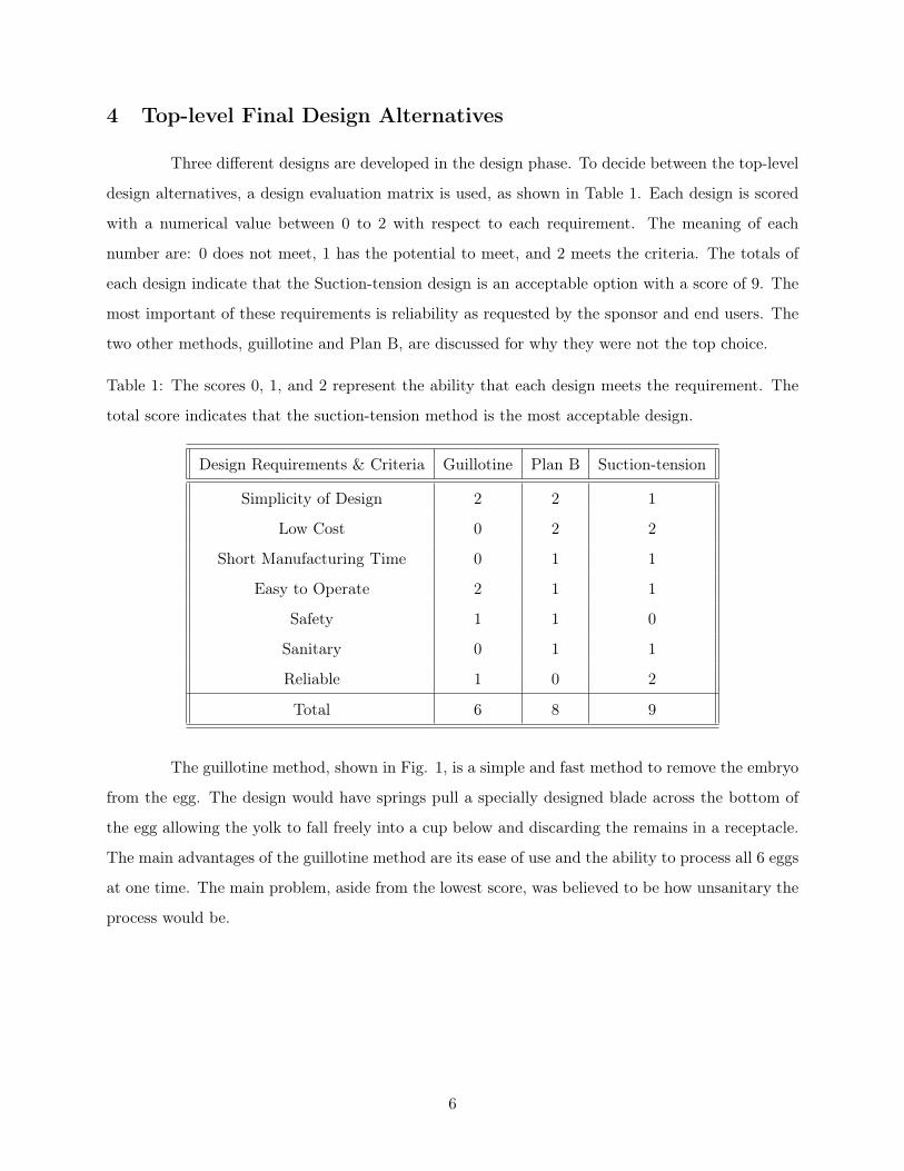
Three different designs are developed in the design phase. To decide between the top-level
design alternatives, a design evaluation matrix is used, as shown in Table 1. Each design is scored
with a numerical value between 0 to 2 with respect to each requirement. The meaning of each
number are: 0 does not meet, 1 has the potential to meet, and 2 meets the criteria. The totals of
each design indicate that the Suction-tension design is an acceptable option with a score of 9. The
most important of these requirements is reliability as requested by the sponsor and end users. The
two other methods, guillotine and Plan B, are discussed for why they were not the top choice.
Table 1: The scores 0, 1, and 2 represent the ability that each design meets the requirement. The
total score indicates that the suction-tension method is the most acceptable design.
Design Requirements & Criteria Guillotine Plan B Suction-tension
Simplicity of Design 2 2 1
Low Cost 0 2 2
Short Manufacturing Time 0 1 1
Easy to Operate 2 1 1
Safety 1 1 0
Sanitary 0 1 1
Reliable 1 0 2
Total 6 8 9
The guillotine method, shown in Fig. 1, is a simple and fast method to remove the embryo
from the egg. The design would have springs pull a specially designed blade across the bottom of
the egg allowing the yolk to fall freely into a cup below and discarding the remains in a receptacle.
The main advantages of the guillotine method are its ease of use and the ability to process all 6 eggs
at one time. The main problem, aside from the lowest score, was believed to be how unsanitary the
process would be.
6
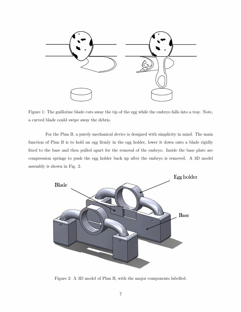
Figure 1: The guillotine blade cuts away the tip of the egg while the embryo falls into a tray. Note,
a curved blade could swipe away the debris.
For the Plan B, a purely mechanical device is designed with simplicity in mind. The main
function of Plan B is to hold an egg firmly in the egg holder, lower it down onto a blade rigidly
fixed to the base and then pulled apart for the removal of the embryo. Inside the base plate are
compression springs to push the egg holder back up after the embryo is removed. A 3D model
assembly is shown in Fig. 2.
Figure 2: A 3D model of Plan B, with the major components labelled.
7
5 Final Design: Handheld Device
The final design consists of the suction cups, vacuum system, puncture device, and me-
chanical levers. These components are what primarily interacts with the quail egg and are the focus
of the final design description.
5.1 Suction Cups
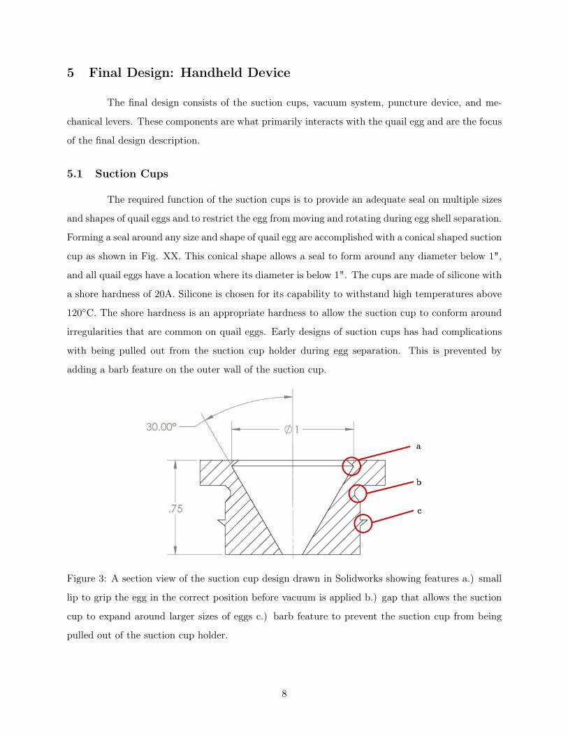
The required function of the suction cups is to provide an adequate seal on multiple sizes
and shapes of quail eggs and to restrict the egg from moving and rotating during egg shell separation.
Forming a seal around any size and shape of quail egg are accomplished with a conical shaped suction
cup as shown in Fig. XX. This conical shape allows a seal to form around any diameter below 1",
and all quail eggs have a location where its diameter is below 1". The cups are made of silicone with
a shore hardness of 20A. Silicone is chosen for its capability to withstand high temperatures above
120�C. The shore hardness is an appropriate hardness to allow the suction cup to conform around
irregularities that are common on quail eggs. Early designs of suction cups has had complications
with being pulled out from the suction cup holder during egg separation. This is prevented by
adding a barb feature on the outer wall of the suction cup.
Figure 3: A section view of the suction cup design drawn in Solidworks showing features a.) small
lip to grip the egg in the correct position before vacuum is applied b.) gap that allows the suction
cup to expand around larger sizes of eggs c.) barb feature to prevent the suction cup from being
pulled out of the suction cup holder.
8
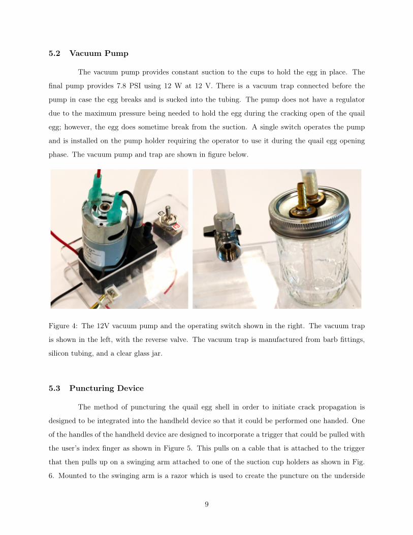
5.2 Vacuum Pump
The vacuum pump provides constant suction to the cups to hold the egg in place. The
final pump provides 7.8 PSI using 12 W at 12 V. There is a vacuum trap connected before the
pump in case the egg breaks and is sucked into the tubing. The pump does not have a regulator
due to the maximum pressure being needed to hold the egg during the cracking open of the quail
egg; however, the egg does sometime break from the suction. A single switch operates the pump
and is installed on the pump holder requiring the operator to use it during the quail egg opening
phase. The vacuum pump and trap are shown in figure below.
Figure 4: The 12V vacuum pump and the operating switch shown in the right. The vacuum trap
is shown in the left, with the reverse valve. The vacuum trap is manufactured from barb fittings,
silicon tubing, and a clear glass jar.
5.3 Puncturing Device
The method of puncturing the quail egg shell in order to initiate crack propagation is
designed to be integrated into the handheld device so that it could be performed one handed. One
of the handles of the handheld device are designed to incorporate a trigger that could be pulled with
the user’s index finger as shown in Figure 5. This pulls on a cable that is attached to the trigger
that then pulls up on a swinging arm attached to one of the suction cup holders as shown in Fig.
6. Mounted to the swinging arm is a razor which is used to create the puncture on the underside
9
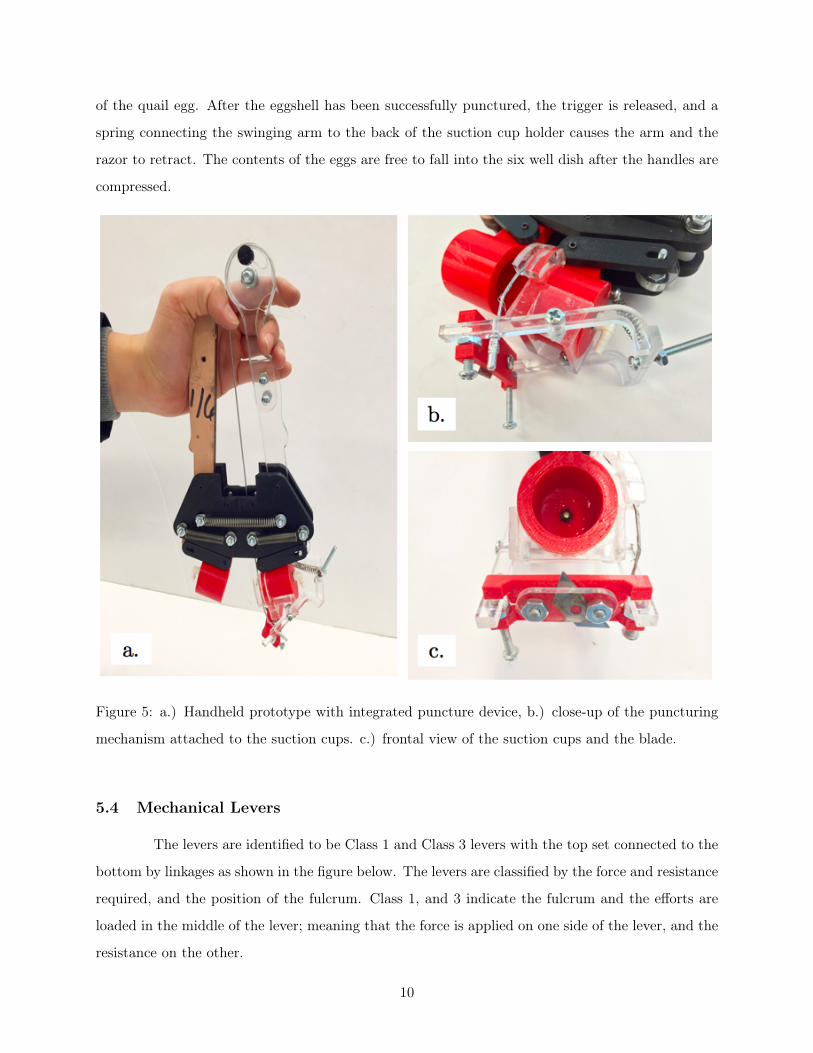
of the quail egg. After the eggshell has been successfully punctured, the trigger is released, and a
spring connecting the swinging arm to the back of the suction cup holder causes the arm and the
razor to retract. The contents of the eggs are free to fall into the six well dish after the handles are
compressed.
Figure 5: a.) Handheld prototype with integrated puncture device, b.) close-up of the puncturing
mechanism attached to the suction cups. c.) frontal view of the suction cups and the blade.
5.4 Mechanical Levers
The levers are identified to be Class 1 and Class 3 levers with the top set connected to the
bottom by linkages as shown in the figure below. The levers are classified by the force and resistance
required, and the position of the fulcrum. Class 1, and 3 indicate the fulcrum and the efforts are
loaded in the middle of the lever; meaning that the force is applied on one side of the lever, and the
resistance on the other.
10

Figure 6: Caption
The purpose of these levers is to decrease the mechanical advantage so when the top levers
(handles) are squeezed together, the cups will spread apart far enough that a quail egg can be
placed between them. After the handles are released, suction is applied and the egg has had the
initial puncture, the handles are squeezed again to break the quail egg open. The low mechanical
advantage helps get the eggshells apart fast enough to let the egg yolk drop into the six well dish
unobstructed.
6 Final Design Evaluation
The method by which this product is evaluated is by testing the final prototype in the
cc-tdi lab with six fertilized incubated quail eggs. Only six were tested because the majority were
unsuccessful extractions.
6.1 Performance&
The puncturing was done by hand in the same method that the mechanical puncturing
device operates. The other elements of the device including separator, suction cups, and vacuum
were used. Six eggs were tested and only one embryo survived. With the puncturing technique of
11
going straight into the shell, the embryo was ruptured every time. The one occurrence where the
egg survived, the blade was inserted at a shallow angle thus confirming that the current puncturing
method does not work.
Each of the suction cups attached to the separator retract unevenly and this makes it
difficult to seat each egg properly between the cups. In addition when an egg fractures in such a
way that the yoke gets sucked into the silicone tubing the cleaning process takes several minutes to
ready the device for the next egg.
6.2 Structural Integrity
The two components of this section are the structural integrity of the device and the eggs as
well. The handheld device is made of high temperature materials (aluminum, Mylar, stainless steel,
and silicone) so that it can be sanitized in an autoclave at 120 degrees Celsius with experiencing
corrosion or warping. The device was not tested in the autoclave to confirm its resilience.
The structural integrity of the eggs is tested when they are inserted into the suction
cups and the clamping force creates a compressive pressure on the shell. Four out of the six eggs
survived the compressive forces even after being punctured from the side. The remaining two eggs
were crushed as a result of the crack initiation.
6.3 Manufacturability & Assembly
The machined parts are made from 6061-T6 aluminum plate of thicknesses 18 ,
14 , and 1 inch
plates. This material is chosen because it may be machined using a variety of tools such as milling,
laser cutting, and water jet. For this prototype the aluminum was machined using a band-saw,
hand drill, and hand files. The fasteners and plumbing parts are ordered from online distributors.
To evaluate this manufacturing process the number of man-hours logged on the construction time
using the previously mentioned tools is ten hours.
The final prototype consists of 124 individual parts and 18 unique parts. Most of the parts
are Mylar washers used for spacing in each pivot joint. Because of the many small parts used for
assembly, care must be taken when assembling the prototype by laying the components out on a
clean flat surface and using a step by step procedure. The figure below shows the general process of
assembling the device. To be broad, first the arm linkages are assembled, then they are mounted to
the base plates, and the plumbing and springs are attached. This assembly process takes a single
person 15 minutes to complete.
12

Figure 7: General procedure of assembling the final product of the quail egg embryo extractor.
From step one to two, the mechanical levers and the suction levers are assembled. In step three and
four, the base plates are assembled on the front and back sides of the device. Lastly, in step five
and six, the suction cups and silicon tubing are connected to the device.
The cost for materials for produce the final prototype consisting of separator, vacuum, and
the puncture device is $291.58. This includes shipping costs and extra materials left over. The total
amount of money spent for the project including research and development is $579.22.
13

7 Conclusion
The final design of the quail egg embryo extractor fell short of meeting the PDS require-
ments in terms of embryo extraction success rate. To meet the requirements, the puncturing method
would have to be improved and the vacuum generation would have to be automatically regulated
to prevent the vacuum from pulling out the contents of the quail egg. It should also be noted that
the yolk sac of fertilized quail eggs are thinner and more sensitive than the yolk sac of unfertilized
quail eggs. For this reason testing should have been done mostly on fertilized quail eggs to be able
to prove in earlier stages if the device was functioning correctly or not.
14
Appendix A: Bio-safety Criteria
Some of the biosafety practices that are applicable to our engineering metrics and con-
straints are summarized in this section. The list of criteria are gathered from Centers for Disease
Control and Prevention. Biosafety Level-2 (BSL-2) is built upon BioSafety Level-1 (BSL-1), which
consists of work involving well-characterized agents not know to cause disease in adult humans and
present minimal potential hazard to laboratory personnel and environment. BSL-2 is suitable for
work involving agents that pose moderate hazards to personnel and the environment. It differs
from BSL-1 such that laboratory personnel have specific training in handling pathogenic agents
and are supervised by scientists competent in handling infectious agents and associated procedures,
access to the laboratory is restricted when work is being conducted, and all procedures in which
infectious aerosols or splashes may be created are conducted in BSCs or other physical containment
equipment.
The following standard, special practices, safety equipment, and facility of the BSL-2 are summa-
rized in the lists below:
1. Agents
1.1. Agents is associated with human disease
1.2. Routes of transmission include per-cutaneous injury, ingestion, mucous membrane expo-
sure
2. Practices
2.1. BSL-1 practice consists of some of the following:
2.1.1. Mouth pipetting is prohibited; mechanical pipetting devices must be used.
2.1.2. Policies for safe handling of sharps, such as needles, scalpels, pipettes, and broken
glassware must be developed and implemented.
2.1.3. Careful management of needles and other sharps are of primary importance. Needles
must not be bent, sheared, broken, recapped, removed from disposable syringes, or
otherwise manipulated by hand before disposal.
2.1.4. Non-disposable sharps must be placed in a hard walled container for transport to a
processing area for decontamination, preferably by autoclaving.
2.2. Decontaminate work surfaces after completion of work and after any spill or splash
of potentially infectious material with appropriate disinfectant.
15
2.3. Decontaminate all cultures, stocks, and other potentially infectious materials before
disposal using an effective method.
2.4. Universal bio-hazard warning signs posted at entrance to laboratory when infectious
agents are present.
2.5. All procedures involving manipulation of infectious materials that may generate an
aerosol should be conducted within a BSC or other physical containment devices.
2.6. Biosafety manual defining any needed waste decontamination or medical surveillance
policies.
3. Primary Barriers & Safety Equipment
3.1. BSCs or other physical containment devices used for all manipulations of agents that
cause splashes or aerosols of infectious materials aerosols of infectious materials.
3.2. Protective laboratory coats, gowns, smocks, or uniforms designated for laboratory use
must be worn while working with hazardous materials.
4. Facilities (Secondary Barriers)
4.1. Biosafety Level-1 consists of the following:
4.1.1. Laboratories should have doors for access control, sink for hand washing, should be
designed so that is can be easily cleaned.
4.1.2. Laboratory furniture must be capable of supporting anticipated loads and uses.
Spaces between benches, cabinets, and equipment should be accessible for cleaning.
4.1.3. Laboratories windows that open to the exterior should be fitted with screens.
4.2. BSCs must be installed so that fluctuations of room air supply and exhaust do not
interfere with proper operations. BSCs should be located away from doors, windows,
that are opened, heavily traveled laboratory areas, and other possible airflow disruptions.
16
Appendix B: External Research Summary
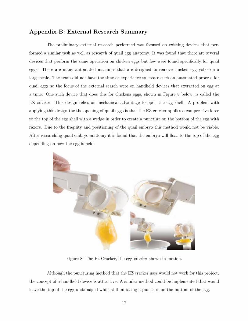
The preliminary external research performed was focused on existing devices that per-
formed a similar task as well as research of quail egg anatomy. It was found that there are several
devices that perform the same operation on chicken eggs but few were found specifically for quail
eggs. There are many automated machines that are designed to remove chicken egg yolks on a
large scale. The team did not have the time or experience to create such an automated process for
quail eggs so the focus of the external search were on handheld devices that extracted on egg at
a time. One such device that does this for chickens eggs, shown in Figure 8 below, is called the
EZ cracker. This design relies on mechanical advantage to open the egg shell. A problem with
applying this design the the opening of quail eggs is that the EZ cracker applies a compressive force
to the top of the egg shell with a wedge in order to create a puncture on the bottom of the egg with
razors. Due to the fragility and positioning of the quail embryo this method would not be viable.
After researching quail embryo anatomy it is found that the embryo will float to the top of the egg
depending on how the egg is held.
Figure 8: The Ez Cracker, the egg cracker shown in motion.
Although the puncturing method that the EZ cracker uses would not work for this project,
the concept of a handheld device is attractive. A similar method could be implemented that would
leave the top of the egg undamaged while still initiating a puncture on the bottom of the egg.
17

Appendix C: Internal Research Summary
Based on the external research, two major design features are focused during the engineer-
ing design process; the method of handling the eggshell during embryo extraction, and the eggshell
puncturing method. Suctions cups are chosen as a primary design feature to hold the egg in its
optimal position and to provide a structured support during embryo extraction.
One of the primary requirement for the design of the suction cups are to be flexible to
conform to various egg sizes, and to be rigid enough to support the egg. Customized suction cups
are made from silicone rubber to fit the two requirements. In additional, a motorized vacuum pump
is employed to supply and maintain a constant suction.
Since the extraction process is conducted in a medical research lab, cross-contamination
and sanitation are concerning factors. Several designs are researched to determine the optimal
cutting device to penetrate the shell to initiate a crack propagation and to pierce through the
membrane. The designs are, a cushioned hammer with a sharp point, to implement a pure separation
force, and a lancing device–similar to the medical device used for taking blood samples. A prototype
is built to evaluate the optimal size and shape of the cutting tool, as well as the spring force required
to penetrate the shell.
18

Appendix D: Detailed Product Design Specifications
The elements of the product design specifications are organized into the table below in or-
der of decreasing importance (e.g. the top indicates the most importance, and bottom indicates the
least).This sequence ranking order was determined by the customer’s feedback using the question-
naire and the team’s judgement.The design specifications shaded in pink indicates high significance,
and the yellow and green represent medium and low importance, respectively.
19
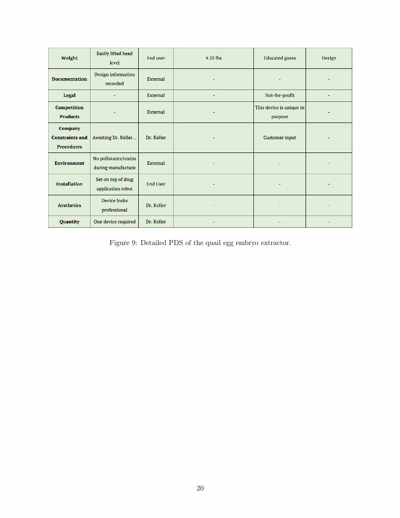
Figure 9: Detailed PDS of the quail egg embryo extractor.
20
Appendix E: CAD Drawings
.25 B
.01
E.0
05
AD
.01
A
B
2X P
.13 B
.005
.01
A
B L
.08
A
C
UO
SF
.02
ISO
MET
RIC
VIEW
FOR
REFE
REN
CE O
NLY
HAN
DLE
LH
SCAL
E 1:
1
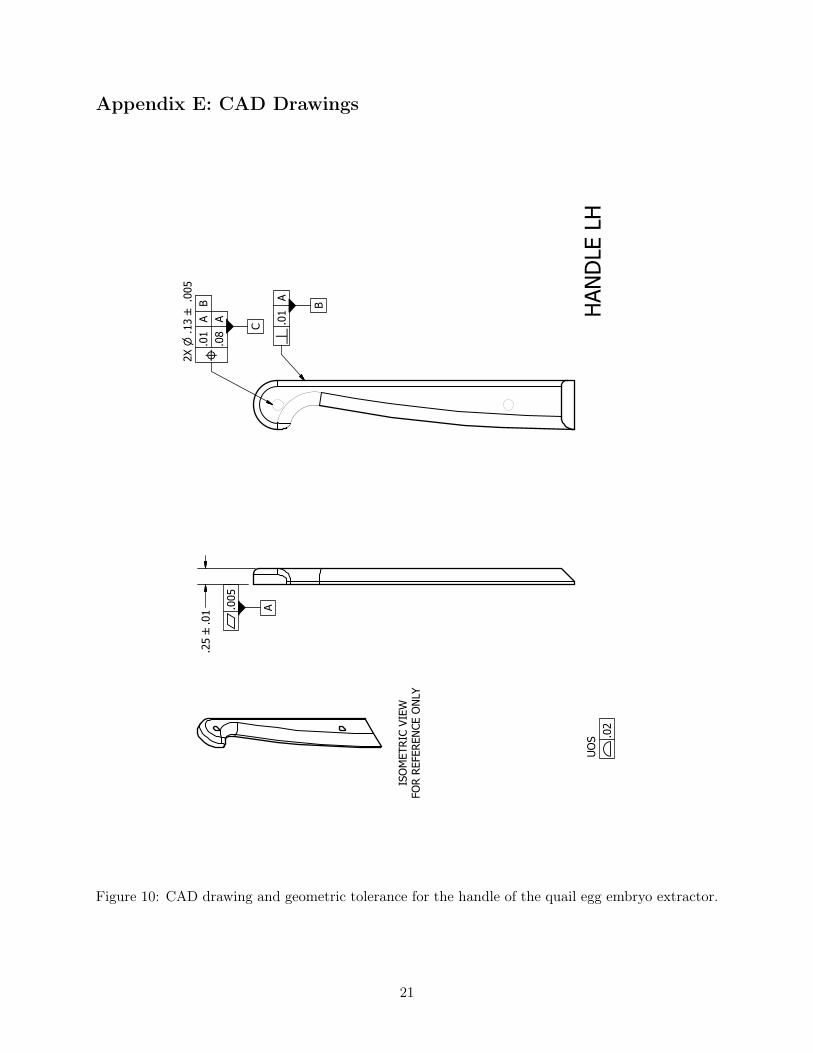
Figure 10: CAD drawing and geometric tolerance for the handle of the quail egg embryo extractor.
21
.25 B
.005
E.0
05
A
D.0
1 A
B
4X P
13/
64 B
.002
.01
A
B L
.08
A
P .1
3 B
.005
L.0
1 A
B
C
C
UO
SF
.02
ISO
MET
RIC
VIEW
FO
R RE
FERE
NCE
ON
LY
LEVE
R SC
ALE
1:2
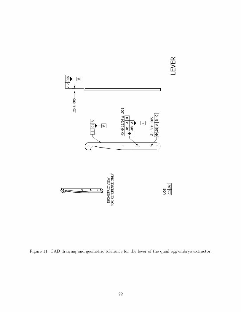
Figure 11: CAD drawing and geometric tolerance for the lever of the quail egg embryo extractor.
22
SECT
ION
A-A
SCAL
E 1
: 1
SECT
ION
B-B
SCAL
E 1
: 1
A A
B B
1.50
B.0
1E
.01
A
D.0
1 A
B
P 1
.00 B
.002
H.0
1 A
B
C
F.0
02
A B
C
V.0
05
C
4X P
.15 B
.005
.01
A
B C
L
.08
A
B IS
OM
ETRI
C VI
EWFO
R RE
FERE
NCE
ON
LY
UO
SF
.02
CUP
HO
LDER
SCAL
E 1:
1
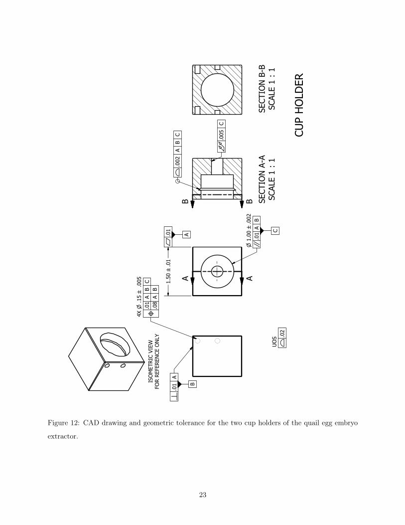
Figure 12: CAD drawing and geometric tolerance for the two cup holders of the quail egg embryo
extractor.
23
E .0
1
A
.50 B
.01
D 0
O
A
B
H .0
1 A
C
2X P
13/
64 B
.005
.01
A
B C
L
.08
A
B
2X P
3/1
6 B
.005
.01
A
B C
L
.08
A
B
UO
SF
.02
ISO
MET
RIC
VIEW
FOR
REFE
REN
CE O
NLY
(1.1
4)(1.8
0) FLAT
PAT
TERN
FOR
REFE
REN
CE O
NLY
CUP
BRAC
KET
SCAL
E 1:
1
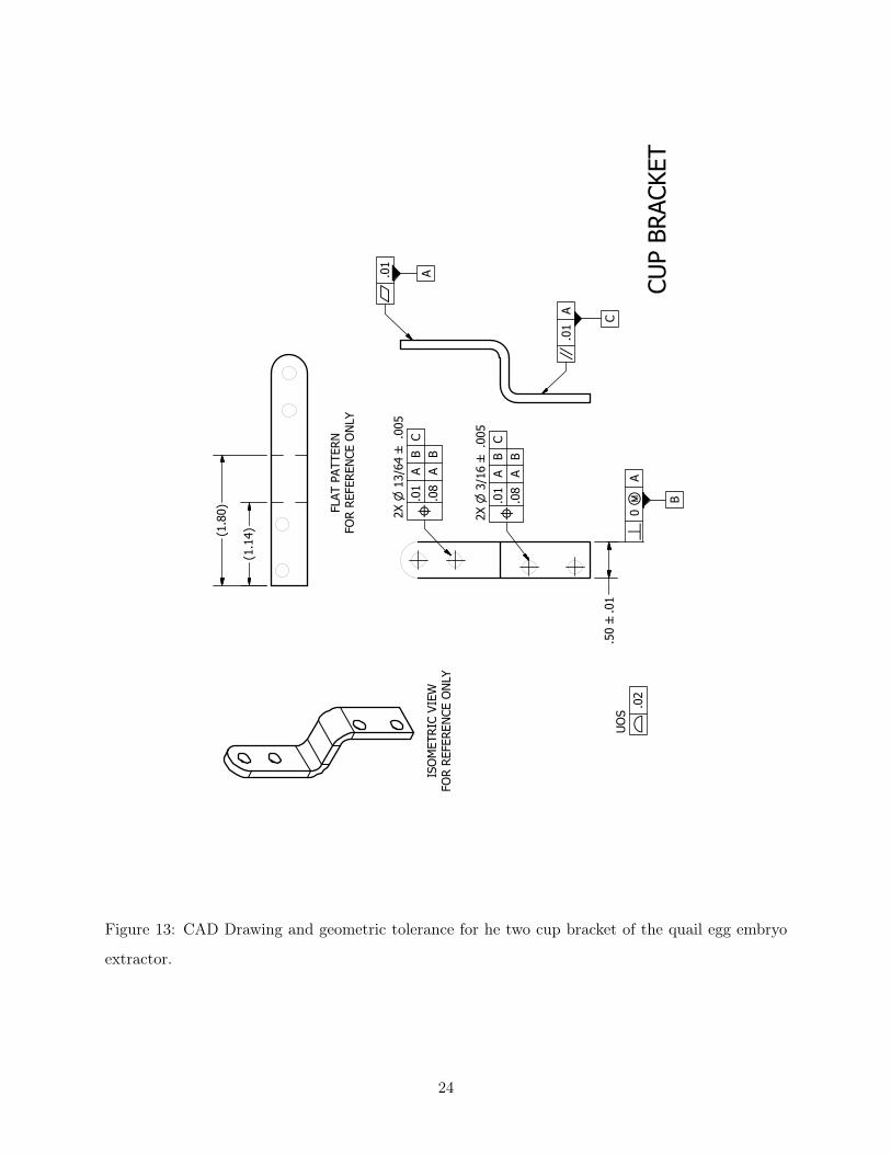
Figure 13: CAD Drawing and geometric tolerance for he two cup bracket of the quail egg embryo
extractor.
24

UO
SF
.02
E .0
1
A
.50 B
.01
D0O
A
B
2X P
13/
64 B
.005
.01
A
B L
.008
A
C
ISO
MET
RIC
VIEW
FO
R RE
FERE
NCE
ON
LY
LIN
K SC
ALE
2:1
Figure 14: CAD drawings and geometric tolerance for the linkages of the quail egg embryo extractor.
25
Appendix F: Bill of Materials
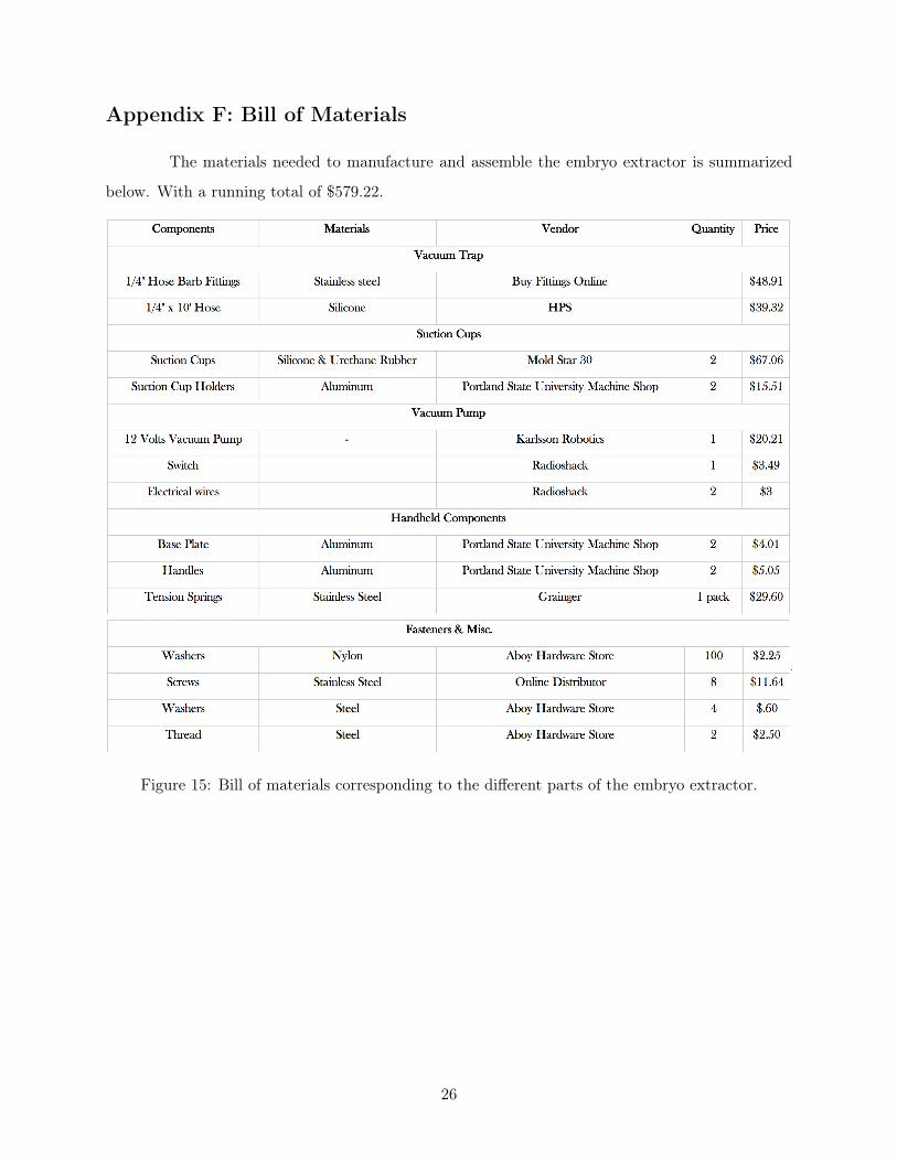
The materials needed to manufacture and assemble the embryo extractor is summarized
below. With a running total of $579.22.
Figure 15: Bill of materials corresponding to the different parts of the embryo extractor.
26
Appendix G: Operational Manual
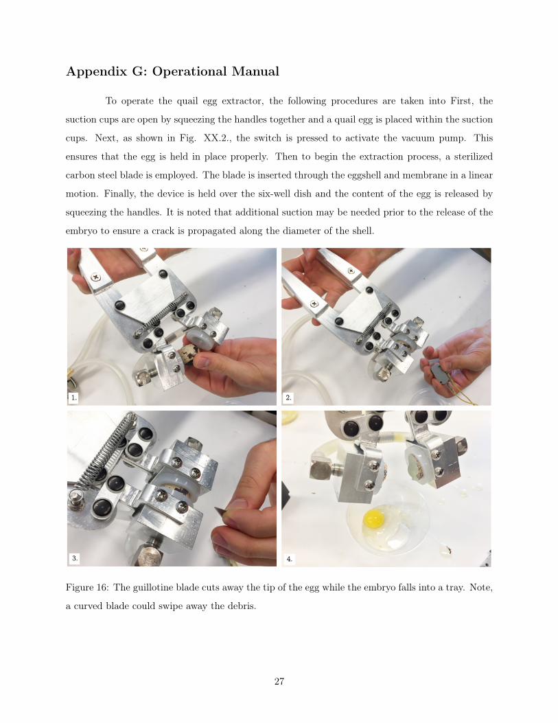
To operate the quail egg extractor, the following procedures are taken into First, the
suction cups are open by squeezing the handles together and a quail egg is placed within the suction
cups. Next, as shown in Fig. XX.2., the switch is pressed to activate the vacuum pump. This
ensures that the egg is held in place properly. Then to begin the extraction process, a sterilized
carbon steel blade is employed. The blade is inserted through the eggshell and membrane in a linear
motion. Finally, the device is held over the six-well dish and the content of the egg is released by
squeezing the handles. It is noted that additional suction may be needed prior to the release of the
embryo to ensure a crack is propagated along the diameter of the shell.
Figure 16: The guillotine blade cuts away the tip of the egg while the embryo falls into a tray. Note,
a curved blade could swipe away the debris.
27
References
[1] Children’s Cancer Therapy Development Institute. (n.d.). Retrieved March 05, 2016, from
http://www.cc-tdi.org/#!mission/ctnu
[2] Ketelaere, B.D., Govaerts, T., Coucke, P., Dewil, E., Vissche, J., Decuypere, E., & Baerde-
maeker, J.D. (2002, 05). Measuring the eggshell strength of 6 different genetic strains
of laying hens: Techniques and comparisons. British Poultry Science, 43 (2), 238-244.
doi:10.1080/007166012012454
[3] Control for Disease Control and Prevention. December 2009 Section IV-Laboratory Biosafety
Level Criteria Microbiological and Biomedical Laboratories (BMBL) 5th. Ed.
from http://www.mun.ca/biolog/desmid/brian/BIOL3530/DEVO_03/ch03f13.jpg
28