Embed Size (px)
Citation preview
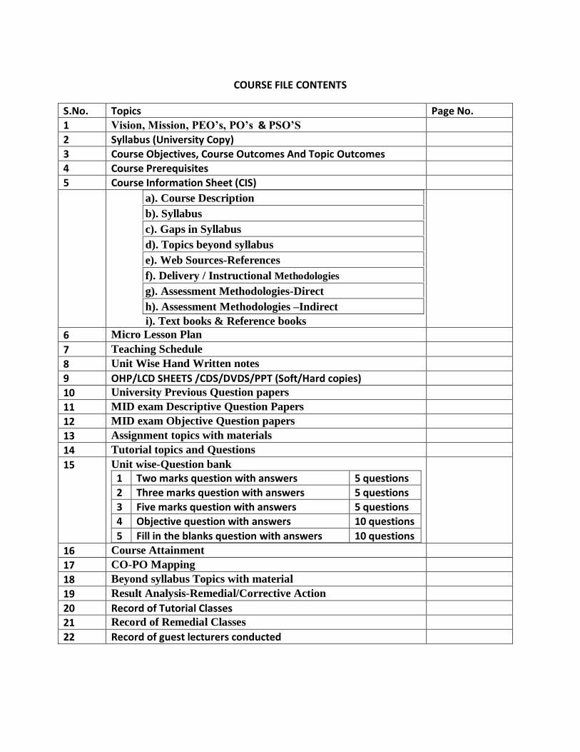
COURSE FILE CONTENTS
S.No. Topics Page No.
1 Vision, Mission, PEO’s, PO’s & PSO’S
2 Syllabus (University Copy)
3 Course Objectives, Course Outcomes And Topic Outcomes
4 Course Prerequisites
5 Course Information Sheet (CIS)
a). Course Description
b). Syllabus
c). Gaps in Syllabus
d). Topics beyond syllabus
e). Web Sources-References
f). Delivery / Instructional Methodologies
g). Assessment Methodologies-Direct
h). Assessment Methodologies –Indirect
i). Text books & Reference books
6 Micro Lesson Plan
7 Teaching Schedule
8 Unit Wise Hand Written notes
9 OHP/LCD SHEETS /CDS/DVDS/PPT (Soft/Hard copies)
10 University Previous Question papers
11 MID exam Descriptive Question Papers
12 MID exam Objective Question papers
13 Assignment topics with materials
14 Tutorial topics and Questions
15 Unit wise-Question bank
1 Two marks question with answers 5 questions
2 Three marks question with answers 5 questions
3 Five marks question with answers 5 questions
4 Objective question with answers 10 questions
5 Fill in the blanks question with answers 10 questions
16 Course Attainment
17 CO-PO Mapping
18 Beyond syllabus Topics with material
19 Result Analysis-Remedial/Corrective Action
20 Record of Tutorial Classes
21 Record of Remedial Classes
22 Record of guest lecturers conducted
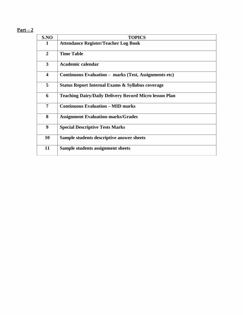
Part – 2
S.NO TOPICS
1 Attendance Register/Teacher Log Book
2 Time Table
3 Academic calendar
4 Continuous Evaluation – marks (Test, Assignments etc)
5 Status Report Internal Exams & Syllabus coverage
6 Teaching Dairy/Daily Delivery Record Micro lesson Plan
7 Continuous Evaluation – MID marks
8 Assignment Evaluation-marks/Grades
9 Special Descriptive Tests Marks
10 Sample students descriptive answer sheets
11 Sample students assignment sheets
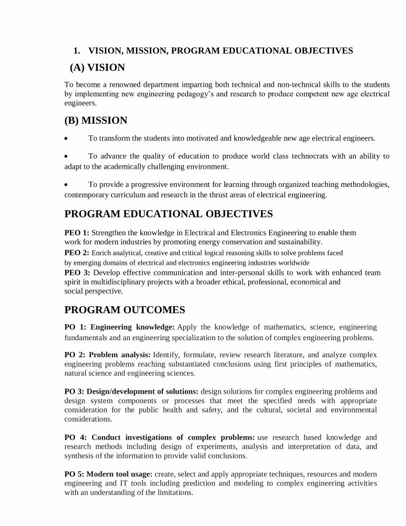
1. VISION, MISSION, PROGRAM EDUCATIONAL OBJECTIVES
(A) VISION
To become a renowned department imparting both technical and non-technical skills to the students
by implementing new engineering pedagogy’s and research to produce competent new age electrical
engineers.
(B) MISSION
To transform the students into motivated and knowledgeable new age electrical engineers.
To advance the quality of education to produce world class technocrats with an ability to
adapt to the academically challenging environment.
To provide a progressive environment for learning through organized teaching methodologies,
contemporary curriculum and research in the thrust areas of electrical engineering.
PROGRAM EDUCATIONAL OBJECTIVES
PEO 1: Strengthen the knowledge in Electrical and Electronics Engineering to enable them
work for modern industries by promoting energy conservation and sustainability.
PEO 2: Enrich analytical, creative and critical logical reasoning skills to solve problems faced
by emerging domains of electrical and electronics engineering industries worldwide
PEO 3: Develop effective communication and inter-personal skills to work with enhanced team
spirit in multidisciplinary projects with a broader ethical, professional, economical and
social perspective.
PROGRAM OUTCOMES
PO 1: Engineering knowledge: Apply the knowledge of mathematics, science, engineering
fundamentals and an engineering specialization to the solution of complex engineering problems.
PO 2: Problem analysis: Identify, formulate, review research literature, and analyze complex
engineering problems reaching substantiated conclusions using first principles of mathematics,
natural science and engineering sciences.
PO 3: Design/development of solutions: design solutions for complex engineering problems and
design system components or processes that meet the specified needs with appropriate
consideration for the public health and safety, and the cultural, societal and environmental
considerations.
PO 4: Conduct investigations of complex problems: use research based knowledge and
research methods including design of experiments, analysis and interpretation of data, and
synthesis of the information to provide valid conclusions.
PO 5: Modern tool usage: create, select and apply appropriate techniques, resources and modern
engineering and IT tools including prediction and modeling to complex engineering activities
with an understanding of the limitations.
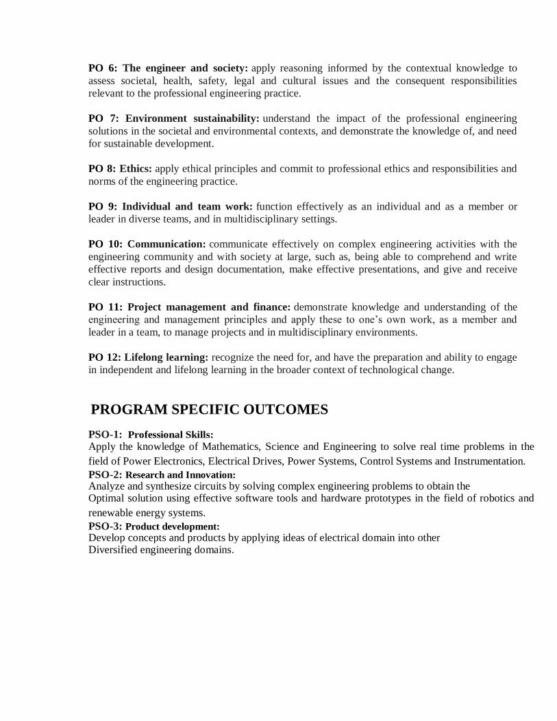
PO 6: The engineer and society: apply reasoning informed by the contextual knowledge to
assess societal, health, safety, legal and cultural issues and the consequent responsibilities
relevant to the professional engineering practice.
PO 7: Environment sustainability: understand the impact of the professional engineering
solutions in the societal and environmental contexts, and demonstrate the knowledge of, and need
for sustainable development.
PO 8: Ethics: apply ethical principles and commit to professional ethics and responsibilities and
norms of the engineering practice.
PO 9: Individual and team work: function effectively as an individual and as a member or
leader in diverse teams, and in multidisciplinary settings.
PO 10: Communication: communicate effectively on complex engineering activities with the
engineering community and with society at large, such as, being able to comprehend and write
effective reports and design documentation, make effective presentations, and give and receive
clear instructions.
PO 11: Project management and finance: demonstrate knowledge and understanding of the
engineering and management principles and apply these to one’s own work, as a member and
leader in a team, to manage projects and in multidisciplinary environments.
PO 12: Lifelong learning: recognize the need for, and have the preparation and ability to engage
in independent and lifelong learning in the broader context of technological change.
PROGRAM SPECIFIC OUTCOMES
PSO-1: Professional Skills:
Apply the knowledge of Mathematics, Science and Engineering to solve real time problems in the
field of Power Electronics, Electrical Drives, Power Systems, Control Systems and Instrumentation. PSO-2: Research and Innovation:
Analyze and synthesize circuits by solving complex engineering problems to obtain the Optimal solution using effective software tools and hardware prototypes in the field of robotics and
renewable energy systems.
PSO-3: Product development:
Develop concepts and products by applying ideas of electrical domain into other Diversified engineering domains.
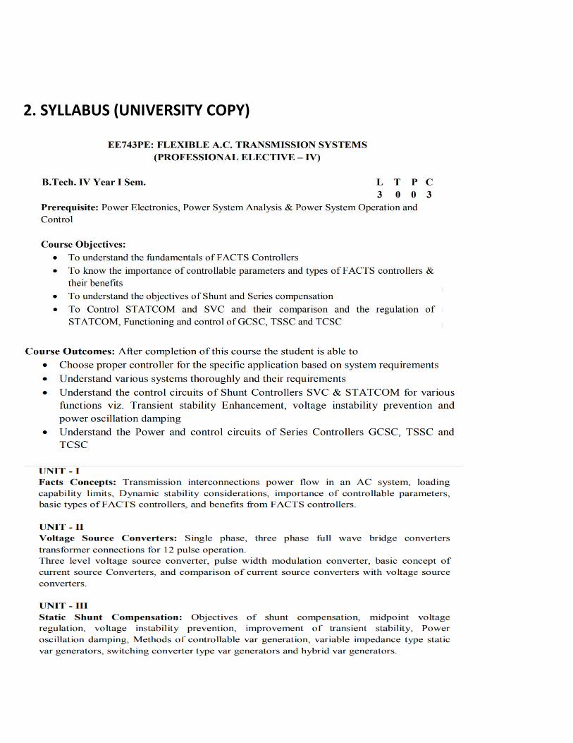
2. SYLLABUS (UNIVERSITY COPY)

3. COURSE OBJECTIVES AND COURSE OUTCOMES
(a)COURSE OBJECTIVES
1. To introduce the reactive power control techniques
2. To educate on static VAR compensators and their applications
3. To provide knowledge on Thyristor controlled series capacitors
4. To educate on STATCOM devices
5. To provide knowledge on FACTS controllers
(b)COURSE OUTCOMES
CO1 Understand the concept of flexible AC transmission and the associated problems.
CO2. Explain the operation of voltage converters
CO3. Explain the operation of static compensation application
CO4. Explain the operation of SVC and STATCOM and its modeling
CO5. Understand the concept of STATIC series compensators .
(c)TOPIC OUTCOMES
S.N. TOPIC TOPIC OUTCOMES
At the end of the topic, the student will be able to
UNIT-I
1. Introduction about FACTS
subject
Introduce the FACTS subject
2. Basic definitions Define terminology in FACTS
3. Basic definitions Define terminology in FACTS
4. power flow in an AC system
Identify the active reactive powers
5. Transmission interconnections power flow
in an AC system
Identify interconnections power flow in an AC
system
6. Transmission line limits and power flow Understand Transmission line limits
7. Dynamic stability considerations Understand stability considerations
8. Stability considerations Understand stability considerations
9. Transmission line capability and limits
Analyze Transmission line capability and
limits
10. basic types of FACTS controllers Explain types of FACTS controllers
11. FACTS controllers Explain types of FACTS controllers
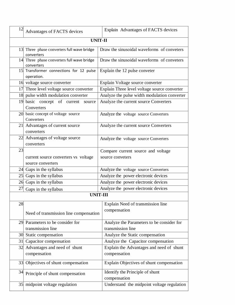
12. Advantages of FACTS devices Explain Advantages of FACTS devices
UNIT-II
13. Three phase converters full wave bridge converters
Draw the sinusoidal waveforms of conveters
14. Three phase converters full wave bridge converters
Draw the sinusoidal waveforms of conveters
15. Transformer connections for 12 pulse
operation.
Explain the 12 pulse conveter
16. voltage source converter Explain Voltage source converter
17. Three level voltage source converter Explain Three level voltage source converter
18. pulse width modulation converter Analyze the pulse width modulation converter
19. basic concept of current source
Converters
Analyze the current source Converters
20. basic concept of voltage source
Converters
Analyze the voltage source Converters
21. Advantages of current source
converters
Analyze the current source Converters
22. Advantages of voltage source
converters
Analyze the voltage source Converters
23.
current source converters vs voltage
source converters
Compare current source and voltage
source conveters
24. Gaps in the syllabus Analyze the voltage source Converters
25. Gaps in the syllabus Analyze the power electronic devices
26. Gaps in the syllabus Analyze the power electronic devices
27. Gaps in the syllabus Analyze the power electronic devices
UNIT-III
28.
Need of transmission line compensation
Explain Need of transmission line
compensation
29. Parameters to be consider for
transmission line
Analyze the Parameters to be consider for
transmission line
30. Static compensation Analyze the Static compensation
31. Capacitor compensation Analyze the Capacitor compensation
32. Advantages and need of shunt
compensation
Explain the Advantages and need of shunt
compensation
33. Objectives of shunt compensation Explain Objectives of shunt compensation
34. Principle of shunt compensation Identify the Principle of shunt
compensation
35. midpoint voltage regulation Understand the midpoint voltage regulation

36. Voltage instability prevention Understand the Voltage instability prevention
37. improvement of transient stability Explain need of transient stability
38. Methods of controllable var generation Explain the Methods of controllable var
generation
39. switching converter type var generators
Explain the switching converter type var
generators
40. switching converter type hybrid var
generators
Explain the hybrid var generators
41. Advantages and need of shunt
compensation
Explain Advantages and need of shunt
compensation
42. Revision
UNIT-IV
43. Introduction to power electronic devices Introduce FACTS devices
44. SVC Observe SVC
45. FC-TCR Analyze the FC-TCR
46. FC-TCR Analyze the FC-TCR
47. TSC-TCR. Analyze the TSC-TCR.
48. TSC-TCR. Analyze the TSC-TCR.
49. Need of STATCOM explain the need of Need of STATCOM
50. STATCOM explain the need of Need of STATCOM
51. SVC Need of SVC
52. The regulation and slope of devices Understand facts devices characteristics
53. Comparison between SVC and
STATCOM
Comparison between SVC and STATCOM
54. Revision Revise the FACTS devices
UNIT-V
55.
Objectives of Series compensation
Explain the Objectives of Series
compensation
56. concept of series capacitive
compensation
Understand the series capacitive
compensation
57. GTO thyristor and other devices Explain GTO thyristor and other devices
58. GTO thyristor-controlled series
capacitor (GSC),
Explain GTO thyristor-controlled series
capacitor (GSC),
59. thyristor switched series capacitor
(TSSC),
Explain thyristor switched series capacitor
(TSSC),
60. thyristor-controlled series capacitor Explain thyristor-controlled series capacitor
(TCSC) (TCSC)
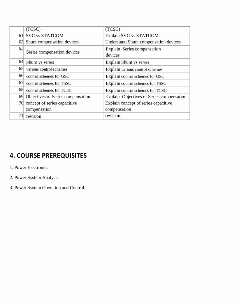
61. SVC vs STATCOM Explain SVC vs STATCOM
62. Shunt compensation devices Understand Shunt compensation devices
63. Series compensation devices
Explain Series compensation
devices
64. Shunt vs series Explain Shunt vs series
65. various control schemes Explain various control schemes
66. control schemes for GSC Explain control schemes for GSC
67. control schemes for TSSC Explain control schemes for TSSC
68. control schemes for TCSC Explain control schemes for TCSC
69. Objectives of Series compensation Explain Objectives of Series compensation
70. concept of series capacitive
compensation
Explain concept of series capacitive
compensation
71. revision revision
4. COURSE PREREQUISITES
1. Power Electronics
2. Power System Analysis
3. Power System Operation and Control

5) CO’S, PO’S MAPPING:
CO&PO Mappings
Course PO1 PO2 PO3 PO4 PO5 PO6 PO7 PO8 PO9 PO10 PO11 PO12 PSO1 PSO2 PSO3
CO1 1 - 2 - 2 3 1 1 - - - 1 1 1 1
CO.2 1 - 2 - 2 3 2 1 - - - 1 1 1 3
CO.3 1 - 2 - 2 3 2 1 - - - 1 1 1 3
CO4 1 - 2 - 2 3 2 1 - - - 1 1 1 3
CO.5 1 - 2 - 2 3 2 1 - - - 1 1 1 1
1.low 2.meduim 3.high

6. COURSE INFORMATION SHEET (CIS)
(a) Course description
PROGRAMME: B. Tech.
(Electrical and Electronics Engineering)
DEGREE: B.TECH
COURSE:FLEXIBLE A.C. TRANSMISSION
SYSTEMS
YEAR: IV SEM: I CREDITS: 3
COURSE CODE: EE743PE
REGULATION: R16
COURSE TYPE: CORE
COURSEAREA/DOMAIN: Electrical CONTACT HOURS: 3+0 (L+T)) hours/Week.
(b) Syllabus
UNIT DETAILS CLASSES
I
UNIT - I
Facts Concepts:
Transmission interconnections power flow in an AC system,
loading capability limits, Dynamic stability considerations,
importance of controllable parameters, basic types of FACTS
controllers, and benefits from FACTS controllers.
12
II
c UN UNIIT – II
3 Volt voltage Source Converters:
Singl single phase, three phase full wave bridge
converters transformer connections for 12 pulse
operation. Three level voltage source converter,
pulse width modulation converter, basic concept of
current source Converters, and comparison of
current source converters with voltage source
converters.
12
III
UNIT - III
Static Shunt Compensation:
Objectives of shunt compensation, midpoint voltage regulation,
voltage instability prevention, improvement of transient stability,
12
Power oscillation damping, Methods of controllable var generation,
variable impedance type static var generators, switching converter
type var generators and hybrid var generators
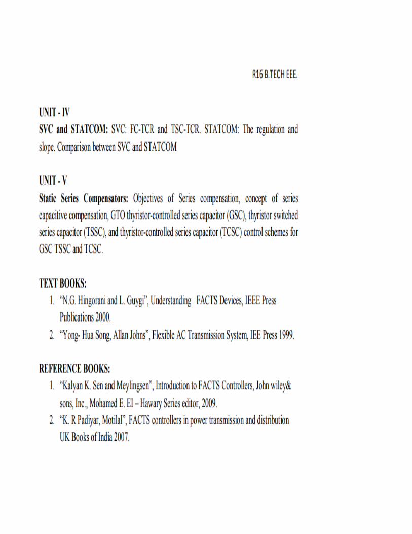
IV
UNIT – IV
SVC and STATCOM:
SVC: FC-TCR and TSC-TCR. STATCOM: The regulation and slope.
Comparison between SVC and STATCOM
13
V
UNIT - V Static Series Compensators:
Objectives of Series compensation, concept of series capacitive
compensation, GTO thyristor-controlled series capacitor (GSC),
thyristor switched series capacitor (TSSC), and thyristor-
controlled series capacitor (TCSC) control schemes for GSC
TSSC and TCSC.
12
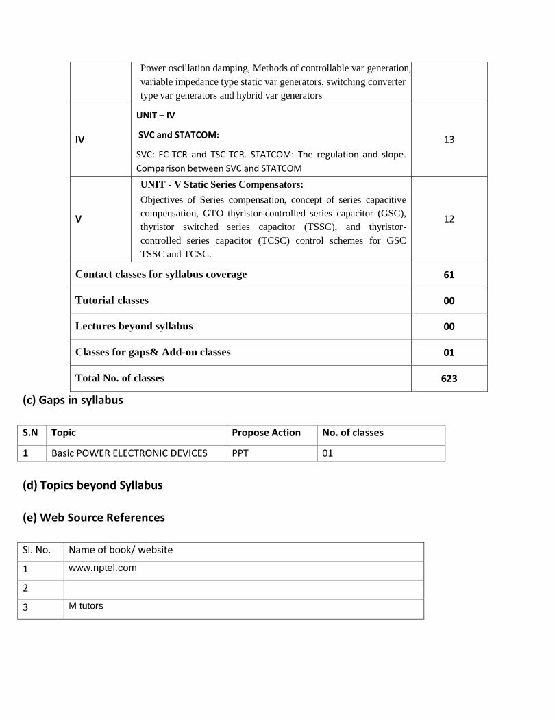
Contact classes for syllabus coverage 61
Tutorial classes 00
Lectures beyond syllabus 00
Classes for gaps& Add-on classes 01
Total No. of classes 623
(c) Gaps in syllabus
S.N Topic Propose Action No. of classes
1 Basic POWER ELECTRONIC DEVICES PPT 01
(d) Topics beyond Syllabus
(e) Web Source References
Sl. No. Name of book/ website
1 www.nptel.com
2
3 M tutors

(f) Delivery / Instructional Methodologies:
CHALK & TALK STUD. ASSIGNMENT WEB RESOURCES
LCD/SMART
BOARDS
STUD. SEMINARS ADD-ON COURSES
(g) Assessment Methodologies - Direct
Assignments Stud. Seminars Tests/Model Exams Univ. Examination
Stud. Lab
Practices
Stud. Viva Mini/Major Projects Certifications
Add-On
Courses
Others
(h) Assessment Methodologies - Indirect
Assessment Of Course Outcomes
(By Feedback, Once)
Student Feedback On
Faculty (Twice)
Assessment Of Mini/Major Projects By
Ext. Experts
Others
(i) Text books and References
Text Books
1. Based Facts Controllers for Electrical Transmission BY R.Mohan Mathur, Rajiv K.Varma
IEEE press and John Wiley & Sons 2002
2. Understanding FACTS -Concepts and Technology of Flexible AC BY Narain G. HingoraniStandard Publishers
Distributors

3. FACTS Controllers in Power Transmission and Distribution BY K.R.Padiyar New Age
International(P) Limited, Publishers2008
Suggested / Reference Books
1. Flexible A.C. Transmission Systems”, Institution of Electrical and ElectronicA.T.John(IEEE),1999
2. Flexible AC Transmission System: Modelling and Control Xiao – Ping Zang,Christian RehtanzSpringer,2012
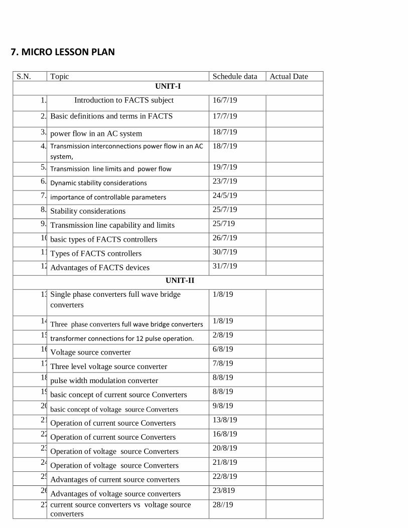
7. MICRO LESSON PLAN
S.N. Topic Schedule data Actual Date
UNIT-I
1. Introduction to FACTS subject 16/7/19
2. Basic definitions and terms in FACTS 17/7/19
3. power flow in an AC system 18/7/19
4. Transmission interconnections power flow in an AC
system,
18/7/19
5. Transmission line limits and power flow 19/7/19
6. Dynamic stability considerations 23/7/19
7. importance of controllable parameters 24/5/19
8. Stability considerations 25/7/19
9. Transmission line capability and limits 25/719
10. basic types of FACTS controllers 26/7/19
11. Types of FACTS controllers 30/7/19
12. Advantages of FACTS devices 31/7/19
UNIT-II
13. Single phase converters full wave bridge
converters
1/8/19
14. Three phase converters full wave bridge converters 1/8/19
15. transformer connections for 12 pulse operation. 2/8/19
16. Voltage source converter 6/8/19
17. Three level voltage source converter 7/8/19
18. pulse width modulation converter 8/8/19
19. basic concept of current source Converters 8/8/19
20. basic concept of voltage source Converters 9/8/19
21. Operation of current source Converters 13/8/19
22. Operation of current source Converters 16/8/19
23. Operation of voltage source Converters 20/8/19
24. Operation of voltage source Converters 21/8/19
25. Advantages of current source converters 22/8/19
26. Advantages of voltage source converters 23/819
27. current source converters vs voltage source
converters
28//19
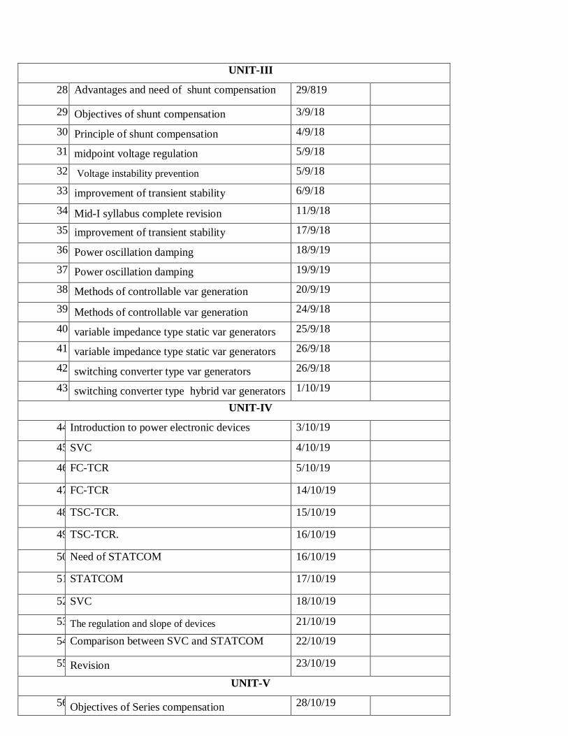
UNIT-III
28. Advantages and need of shunt compensation 29/819
29. Objectives of shunt compensation 3/9/18
30. Principle of shunt compensation 4/9/18
31. midpoint voltage regulation 5/9/18
32. Voltage instability prevention 5/9/18
33. improvement of transient stability 6/9/18
34. Mid-I syllabus complete revision 11/9/18
35. improvement of transient stability 17/9/18
36. Power oscillation damping 18/9/19
37. Power oscillation damping 19/9/19
38. Methods of controllable var generation 20/9/19
39. Methods of controllable var generation 24/9/18
40. variable impedance type static var generators 25/9/18
41. variable impedance type static var generators 26/9/18
42. switching converter type var generators 26/9/18
43. switching converter type hybrid var generators 1/10/19
UNIT-IV
44. Introduction to power electronic devices 3/10/19
45. SVC 4/10/19
46. FC-TCR 5/10/19
47. FC-TCR 14/10/19
48. TSC-TCR. 15/10/19
49. TSC-TCR. 16/10/19
50. Need of STATCOM 16/10/19
51. STATCOM 17/10/19
52. SVC 18/10/19
53. The regulation and slope of devices 21/10/19
54. Comparison between SVC and STATCOM 22/10/19
55. Revision 23/10/19
UNIT-V
56. Objectives of Series compensation 28/10/19

57. concept of series capacitive compensation 29/10/19
58. GTO thyristor and other devices 30/10/19
59. GTO thyristor-controlled series capacitor
(GSC),
31/10/19
60. thyristor switched series capacitor (TSSC), 31/10/19
61. thyristor-controlled series capacitor (TCSC) 1/11/19
62. SVC vs STATCOM 4/11/19
63. Shunt compensation devices 5/11/19
64. Series compensation devices 6/11/19
65. Shunt vs series 6/11/19
66. various control schemes 7/11/19
67. control schemes for GSC 8/11/19
68. control schemes for TSSC 11/11/19
69. control schemes for TCSC 12/11/19
70. REVISION CMPLETON OF MID-2
SYLLABUS
13/11/19
71. CMPLETON OF MID-2 SYLLABUS
PREFINAL
13/11/19
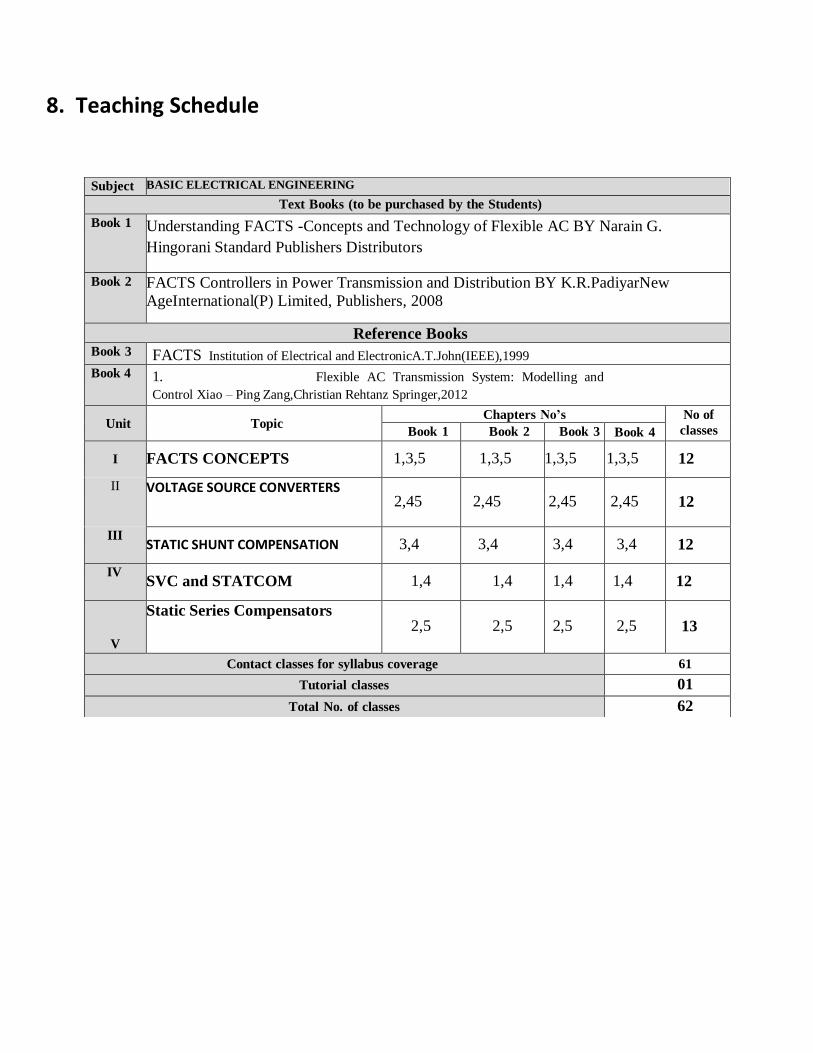
8 8. Teaching Schedule
Subject BASIC ELECTRICAL ENGINEERING
Text Books (to be purchased by the Students)
Book 1 Understanding FACTS -Concepts and Technology of Flexible AC BY Narain G.
Hingorani Standard Publishers Distributors
Book 2 FACTS Controllers in Power Transmission and Distribution BY K.R.PadiyarNew
AgeInternational(P) Limited, Publishers, 2008
Reference Books Book 3 FACTS Institution of Electrical and ElectronicA.T.John(IEEE),1999 Book 4 1. Flexible AC Transmission System: Modelling and
Control Xiao – Ping Zang,Christian Rehtanz Springer,2012
Unit
Topic Chapters No’s No of
classes Book 1 Book 2 Book 3 Book 4
I FACTS CONCEPTS 1,3,5 1,3,5 1,3,5 1,3,5 12
II VOLTAGE SOURCE CONVERTERS 2,45 2,45 2,45 2,45 12
III STATIC SHUNT COMPENSATION 3,4 3,4 3,4 3,4 12
IV SVC and STATCOM 1,4 1,4 1,4 1,4 12
V
Static Series Compensators 2,5 2,5 2,5 2,5 13
Contact classes for syllabus coverage 61
Tutorial classes 01
Total No. of classes 62
9. Unit-wise Hand written notes (Soft copy and Hard copy)
UNITE-WISE LECTURE NOTES
HAPTER 1
FACTS CONTROLLERS
INTRODUCTION
The electric power supply systems of whole world are interconnected, involving connections inside the
utilities, own territories with external to inter-utility, internationals to inter regional and then international
connections. This is done for economic reasons, to reduce the cost of electricity and to improve reliability
of power supply. We need the interconnections to pool power plants and load centers in order to minimize
the total power generation capacity and fuel cost. Transmission lines interconnections enable to supply,
electricity to the loads at minimized cost with a required reliability. The FACTS Technology is adopted in
the transmissions to enhance grid reliability and to over come the practical difficulties which occur in
mechanicaldevises used as controllers of the transmission network.The FACTS Technology has opened a
new opportunity to the transmission planner for controlling power and enhancing the useable capacity
presently, also to upgrade the transmission lines. The current through the line can be controlled at a
reasonable cost which enables a large potential of increasing the capacity of existing lines with large
conductors and by the use of FACTS controllers the power flow through the lines is maintained stable. The
FACTS controllers control the parameters governing the operation of transmission systems, such as series
impedance, shunt impedance, current, voltage, phase angle and damping of oscillations at various
frequencies below the rated frequency.In an A.C power flow, the electrical generation and load must be
balanced all the times. Since the electrical system is self regulating, therefore, if one of the generators
supplies less powerthan the load, the voltage and frequency drop, thereby load goes on decreasing to
equalize the generated power by subtracting the transmission losses. How ever there is small margin of self
regulating. If voltage is dropped due to reactive power, the load will go up and frequency goes on
decreasing and the system will collapse ultimately. Also the system will collapse if there is a large reactive

power available in it. In case of high power generation the active power flows
from surplus generating area to the deficit area.
POWER FLOW
Consider a simple case of power flow in parallel paths. Here power flows from surplus generation area
to the deficit generation area. Power flow is based on the inverse of line impedance. It is likely that
lower impedance line become overloaded and limits the loading on both the paths, though the higher
impedance area is not fully loaded. There would not be any chance to upgrade the current capacity of
the overloaded path, because it would further decrease the impedance. The power flow with HVDC
converters is controlled by high speed HVDC converters. The parallel A.C. transmission maintains the
stability of power flow. The power flow control with FACTS controllers can be carried out by means of
controlling impedance, phase angle and by injected voltage in series.
1400 MW
(a)
A
10 C
2000 MW 10
600
MW
5 1600
MW
3000
MW
load
1000 MW

A 2000
MW
-5
600
MW
10
1750 MW
10
5
125
0
MW
C
3000
MW
load
B 1000 MW
(b)
MW load
A
2000MW
-4.24
1750 MW
10 C
250 MW 10 5 3000 MW load
1250 MW
7
B 1000 MW
(d)
Fig 2.1 Power Flow in Meshed Paths
A 1750 MW
10C
250 MW 10 5 3000
2000MW
7
B 1000 MW
(c)

-
-
For understanding free flow of power, consider a simplified case in which two generators are sending
power to load center from different sites. The Mesh network has the lines AB, BC and AC having
continuous rating of 1000 MW, 1250 MW respectively. If one of the generators is generating 2000 MW
and the other 1000 MW, a total power of 3000 MW would be delivered to the load center. In Fig 2.1 (a)
the three impedances 10Ω, 5Ω and 10Ω, carry the powers 600 MW, 1600 MW and 1400 MW
respectively. Such a situation would overload line BC and therefore generation would have to be
decreased at „B‟ and increased at „A‟ in order to meet the load without overloading the line BC.
If a capacitor of reactance (-5Ω) at the synchronous frequency is inserted in the line AC as in Fig 2.1
(b), it reduces the line impedance from 10Ω to 5Ω so that the power flow through the lines AB, BC and
AC are 250 MW, 1250 MW and 1750 MW respectively. It is clear that if the series capacitor is adjusted
the power flow level may be realized. The complication is if the series capacitor is mechanically
controlled it may lead to sub synchronous resonance. This resonance occurs when one of the
mechanical resonance frequencies of the shaft of a multiple- turbine generator unit coincides with
normal frequency by subtracting the electrical resonance frequency of the capacitor with the inductive
load impedance of the line. Then the shaft will be damaged.
If the series capacitor is thyristor controlled, it can be varied whenever required. It can be modulated to
rapidly damped and sub synchronous conditions. Also can be modulated at damped low frequency
oscillations. The transmission system to go from one steady-state condition to another without the risk
of damaging the shaft, the system collapse. In other words thyristor controlled series capacitor can
enhance the stability of network similarly as in Fig 2.1(c). The impedance of line BC is increased by
inserting an inductor of reactance in series

-
-
with the line AB, the series inductor which is controlled by thyristor could serve to adjust the steady-
state power flow and damped unwanted oscillations.
Another option of thyristor controlled method is, phase angle regulator could be installed instead of
series capacitor in the line as in Fig 2.1(d). The regulator is installed in line AC to reduce the total phase
angle difference along the line from 8.5 degree to 4.26 degrees. Thus the combination of Mesh and
thyristor control of the phase angle regulator may reduce the cost. The same result could be achieved by
injecting a variable voltage in one of the lines. Balancing
of power flow in the line is carried out by the use of FACTS controller in the line.
LOADING CAPABILITY LIMITS
For the best use of the transmission and to improve the loading capability of the system one has to over
come the following three kinds of limitations:-
Thermal Limitations
Dielectric Limitations
Limitations of Stability
Thermal Limitations
Thermal capability of an overhead lines is a function of the ambient temperature, wind conditions,
conductors condition and ground clearance. It varies by a factor of 2 to 1 due to variable environment
and the loading history. It needs to find out the nature of environment and other loading parameters. For
this, off-line computer programs are made use to calculate a line loading capability based on available
ambient environment and present loading history. The over load line monitoring devices are also used
to know the on line loading capability of the line. The normal loading of the line is also decided on a
loss evaluation basis which may vary for many reasons. The increase of the rating of transmission
line involves the

-
-
consideration of the real time rating of a transformer which is a function of ambient temperature, aging
of transformer and present loading history of off-line and on-line monitoring. The loading capability of
transformer is also used to obtain real time loading capability. Enhancement of cooling of transformer is
also a factor of increase of load on transmission line. From the above discussion it is necessary of
upgrading line loading capability which can be done by changing the conductor of higher current rating
which requires the structural upgrading. The loading capability of line is also achieved by converting a
single circuit to double circuit line. If the higher current capability is available then the question arises,
how to control this high current in the line, also, the acceptance of sudden voltage drop with such high
current etc. The FACTS technology helps in making an effective use of the above technique of
upgrading the loading capability of line.
Dielectric Limitations
From insulation point of view, many transmission lines are designed very conservatively. For a normal
voltage rating, it is rarely possible to increase normal operation by +10% voltages, e.g. 500 kV, - 550
kV or even higher. Care must be taken such that the dynamic and transient over voltages are within the
limit. Modern type of gapless arresters, or line insulators with internal gapless arresters or powerful
Thyristor-controlled over voltage suppressors at the sub-stations are used to increase the line and sub
station voltage capability. The FACTS technology could be used to ensure acceptable over-voltage and
power conditions.
Limitations of Stability
There are a number of stability issues that limit the transmission capability. They are:
Transient Stability
Dynamic Stability
-
-
Steady-state Stability
Frequency Collapse
Voltage Collapse
Sub synchronous Resonance
IMPORTANCE OF CONTROLLABLE PARAMETERS
Control of line impedance „X‟ with a Thyristor controlled series capacitor can
provide a powerful means of current control.
When the angle is not large in some cases the control of „X‟ or the angle
provides the control of active power.
Control of angle with a phase angle regulator controls the driving voltage,
which provides the powerful means of controlling the current flow and hence active
power flow when the angle is not large.
Injecting a voltage in series with the line, which is perpendicular to the current
flow can increase or decrease the magnitude of current flow. Since the current flow lags
the driving voltage by 90º, this means injection of reactive power in series
compensation can provide a powerful means of controlling the line current and hence
the active power when the angle is not large.
Injecting voltage in series with line with any phase angle with respect to the
driving voltage can control the magnitude and the phase of the line current. This means
that injecting a voltage phasor with variable phase angle can provide a powerful means
of controlling the active and reactive power flow. This requires injection if both active
and reactive power are in series.

-
-
When the angle is not-large, controlling the magnitude of one or the other line
voltages with a Thyristor-controlled voltage regularly can very cost-effective means for
the control of reactive power flow through the inter connection.
Combination of the line impedance with a series controller and voltage
regulation with shunt controller can also provide a cost effective means to control
both the active and
reactive power flow between the two systems.
TYPES OF FACTS CONTROLLERS
In general FACTS controllers can be classified into four categories.
Series controllers
Shunt controllers
Combined series-series controllers
Combined series-shunt controllers
(a) General symbol of FACTS controller
(b) Series controller
Line
D.C Power Link
(c) Shunt
controller
(d) Unified Series controller
Line
-
-
Line
Line
(e)
Coordinated
Controller DC Power Link
(f) Unified Series
shunt controller
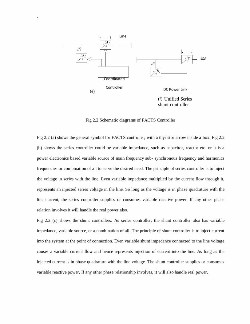
Fig 2.2 Schematic diagrams of FACTS Controller
Fig 2.2 (a) shows the general symbol for FACTS controller; with a thyristor arrow inside a box. Fig 2.2
(b) shows the series controller could be variable impedance, such as capacitor, reactor etc. or it is a
power electronics based variable source of main frequency sub- synchronous frequency and harmonics
frequencies or combination of all to serve the desired need. The principle of series controller is to inject
the voltage in series with the line. Even variable impedance multiplied by the current flow through it,
represents an injected series voltage in the line. So long as the voltage is in phase quadrature with the
line current, the series controller supplies or consumes variable reactive power. If any other phase
relation involves it will handle the real power also.
Fig 2.2 (c) shows the shunt controllers. As series controller, the shunt controller also has variable
impedance, variable source, or a combination of all. The principle of shunt controller is to inject current
into the system at the point of connection. Even variable shunt impedance connected to the line voltage
causes a variable current flow and hence represents injection of current into the line. As long as the
injected current is in phase quadrature with the line voltage. The shunt controller supplies or consumes
variable reactive power. If any other phase relationship involves, it will also handle real power.
-
-
Fig 2.2 (d) shows the combination of two separate series controllers, which are controlled in a
coordinated manner, in a multi line transmission system. Other wise it could be unified controller. As
shown in Fig 2.2 (d) the series controllers provide independent series reactive compensation for each
line and also transfer the real power among the lines via the unified series-series controller, referred to
as inter-line power flow controller, which makes it possible to balance both the real and reactive power
flow in the lines and thereby maximizing the utilization of transmission system. Note that the term
“unified” here means that the D.C terminals of all controller converters are connected together for real
power transfer.
Fig 2.2 (e & f) shows the combined series-shunt controllers. This could be a combination of separate
shunt and series controllers, which are controlled in coordinated manner in Fig 2.2 (e) or a unified
power flow controller with series and shunt elements in Fig 2.2 (f). The principle of combined shunt
and series controllers is, it injects current into the system with the shunt part of the controller and
voltage through series part. However, when the shunt and series controllers are unified, there can be
a real power exchange between the series and shunt
controllers via the power link.
BENEFITS FROM FACTS CONTROLLER
,
Control of power flow is in order, meet the utilities, own needs, ensure
optimum power flow, and ride through emergency conditions or a combination of all.
Increase the loading capability of lines to their thermal capabilities, including
short term and seasonal, this can be done by overcoming other limitations and sharing
of power among lines according to their capability.
-
-
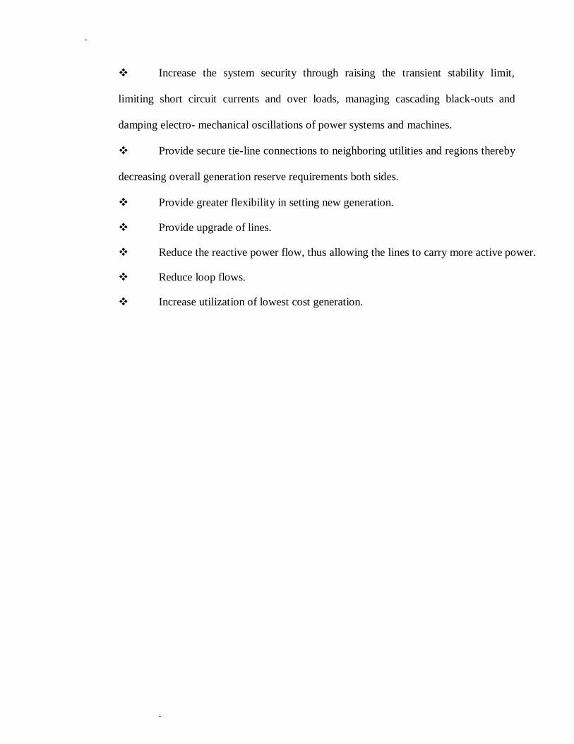
Increase the system security through raising the transient stability limit,
limiting short circuit currents and over loads, managing cascading black-outs and
damping electro- mechanical oscillations of power systems and machines.
Provide secure tie-line connections to neighboring utilities and regions thereby
decreasing overall generation reserve requirements both sides.
Provide greater flexibility in setting new generation.
Provide upgrade of lines.
Reduce the reactive power flow, thus allowing the lines to carry more active power.
Reduce loop flows.
Increase utilization of lowest cost generation.

-
-
UNIT - II
VOLTAGE SOURCE CONVERTERS
1
11 3 31
Vd
iab
4
41 2 21
Vab
P & Q
AC System
Fig 2.3 (a) Single Phase Full Wave Bridge Converters
Operation of Single Phase Bridge Converter
Fig 2.3 (a) shows a single phase bridge converter consisting of four valves i.e. valves (1-1') to (4 -4'), a
capacitor to provide stiff D.C. Voltage and two A.C. connection points „a‟ and „b‟. The designated
valve numbers represent their sequence of turn on and turn off operation. The

-
-
AC Voltage
D.C. voltage is converted to A.C. voltage with the appropriate valve turn-off sequence, as explained
below. As in the first wave form 2.3 (b) when devices 1and 2 are turned on voltage
„Vab‟ becomes „+Vd‟ for one half cycle and when devices 3 and 4 turned off „Vab‟ becomes „- Vb‟ for
the other half cycle. Suppose the current flow in Fig 2.3 (c) is A.C. wave form which is a sinusoidal
wave form „Iab,‟ the angle „θ‟ leads with respect to the square-wave voltage wave form t1 the operation
is illustrated.
Vab AC Voltage
Iab
Id
V1-1
-Vd
AC Current
DC Current Rectifier
Inerter
Value Voltage
Vas
Ias
(b)
Fig 2.3(b) Single phase full wave bridge converter
1. From instant t1 to t2 when devices 1 and 2 are ON and 3 and 4 are OFF, „Vab‟ is +ve and Iab
is -ve. The current flows through device 1 into A.C. phase „a‟ and then out of A.C. phase „b‟ through
device „2‟ with power flow from D.C. to A.C. (inverter action).
2. From instant t2 to t3 the current reverses i.e. becomes +ve and flows through diodes 1' and 2'
with power flow from A.C. to D.C. (rectifier action)
-
-
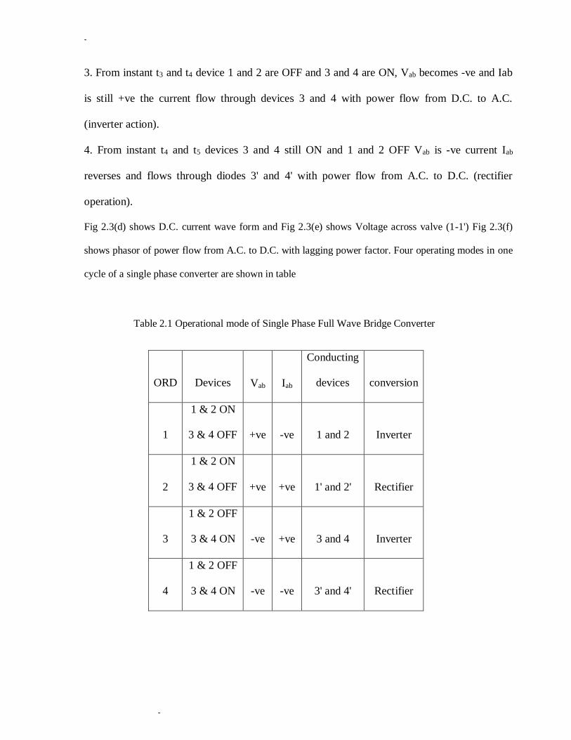
3. From instant t3 and t4 device 1 and 2 are OFF and 3 and 4 are ON, Vab becomes -ve and Iab
is still +ve the current flow through devices 3 and 4 with power flow from D.C. to A.C.
(inverter action).
4. From instant t4 and t5 devices 3 and 4 still ON and 1 and 2 OFF Vab is -ve current Iab
reverses and flows through diodes 3' and 4' with power flow from A.C. to D.C. (rectifier
operation).
Fig 2.3(d) shows D.C. current wave form and Fig 2.3(e) shows Voltage across valve (1-1') Fig 2.3(f)
shows phasor of power flow from A.C. to D.C. with lagging power factor. Four operating modes in one
cycle of a single phase converter are shown in table
Table 2.1 Operational mode of Single Phase Full Wave Bridge Converter
ORD
Devices
Vab
Iab
Conducting
devices
conversion
1
1 & 2 ON
3 & 4 OFF
+ve
-ve
1 and 2
Inverter
2
1 & 2 ON
3 & 4 OFF
+ve
+ve
1' and 2'
Rectifier
3
1 & 2 OFF
3 & 4 ON
-ve
+ve
3 and 4
Inverter
4
1 & 2 OFF
3 & 4 ON
-ve
-ve
3' and 4'
Rectifier

-
-
P
(a) Three Phase Full Wave Bridge Converters
+Vd/2
Va 1
4
Phase to DC mid point
4
-Vd/2
+Vd/2
Vb 3 3
6 6
+Vd/2
Vc 5
2
-Vd/2
5
2
-Vd/2
(b) (b)
1 11 3 31 5 51
Vd N a
b
4 41 6 61
c
2 21

-
-
Vab=Va-
Vb
1,6 1,3 4,6
3,
4
1,6
3,4
ph-to-ph voltage
Vbc=Vb-
Vc
Vca=Vc-
Va
1,5
5,6
1,2
2,6
3,4
3,2
5,4
3,
5
5,6
1,2
3
,
2
5,
4
5,6
(c) (c)
ia
(d) (d)
+vd/6
Vn
-vd/6
nature
voltag
e
(e) (e)
Van
(f) (f)
t1 t2 t3 11
4 11 4
41 1 41 1 41
1
+vd/3 Ph-to-N
voltage
-vd/3

-
-
V1 Valve
(g) voltage
-
-
(h) (h)
(i) (i)
Id
(j) (j)
Total DC Bus Current
(k) (k)
DC Current with upf inverter operation
Fig 2.4 Three phase full wave bridge converter
(l)
11
4 1 41
1 4 1 4 DC Current from
ph-a
31 61 31
DC Current from ph-b
3 6 3 6
51 21 51 21
DC Current from ph-c
2 5 2 5
-
FACTS Controllers 26 -
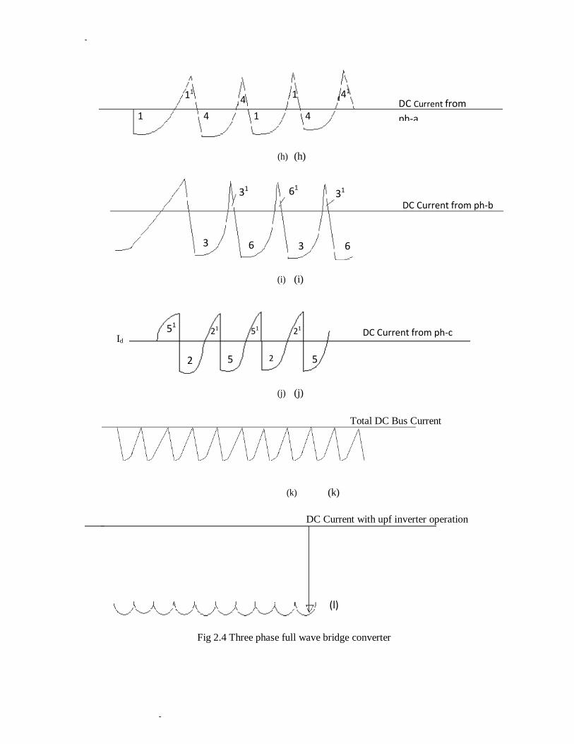
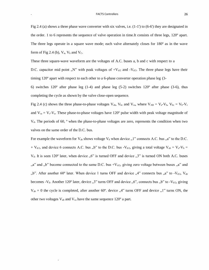
Fig 2.4 (a) shows a three phase wave converter with six valves, i.e. (1-1') to (6-6') they are designated in
the order. 1 to 6 represents the sequence of valve operation in time.It consists of three legs, 120º apart.
The three legs operate in a square wave mode; each valve alternately closes for 180º as in the wave
form of Fig 2.4 (b), Va, Vb and VC.
These three square-wave waveform are the voltages of A.C. buses a, b and c with respect to a
D.C. capacitor mid point „N‟ with peak voltages of +Vd/2 and -Vd/2. The three phase legs have their
timing 120º apart with respect to each other to a 6-phase converter operation phase leg (3-
6) switches 120º after phase leg (1-4) and phase leg (5-2) switches 120º after phase (3-6), thus
completing the cycle as shown by the valve close-open sequence.
Fig 2.4 (c) shows the three phase-to-phase voltages Vab, Vbc and Vca, where VAB = Va-Vb, Vbc = Vb-Vc
and Vca = Vc-Va. These phase-to-phase voltages have 120º pulse width with peak voltage magnitude of
Vd. The periods of 60, º when the phase-to-phase voltages are zero, represents the condition when two
valves on the same order of the D.C. bus.
For example the waveform for Vab shows voltage Vd when device „1‟ connects A.C. bus „a‟ to the D.C.
+ Vd/2, and device 6 connects A.C. bus „b‟ to the D.C. bus -Vd/2, giving a total voltage Vab = Va-Vb =
Vd. It is seen 120º later, when device „6‟ is turned OFF and device „3‟ is turned ON both A.C. buses
„a‟ and „b‟ become connected to the same D.C. bus +Vd/2, giving zero voltage between buses „a‟ and
„b‟. After another 60º later. When device 1 turns OFF and device „4‟ connects bus „a‟ to -Vd/2, Vab
becomes -Vd. Another 120º later, device „3‟ turns OFF and device „6‟, connects bus „b‟ to -Vd/2, giving
Vab = 0 the cycle is completed, after another 60º. device „4‟ turns OFF and device „1‟ turns ON, the
other two voltages Vab and Vca have the same sequence 120º a part.
-
-
The turn ON and turn OFF of the devices establish the wave forms of the A.C. bus voltages in relation
to the D.C. voltage, the current flows itself, is the result of the interaction of the A.C. voltage with the
D.C. system. Each converter phase-leg can handle resultant current flow in either direction. In fig 2.4
(d) A.C. current „Ia‟ in phase „a‟ with +ve current representing current from A.C. to D.C. side for
simplicity, the current is assumed to have fundamental frequency only. From point t1 to t2. For example
phase „a‟ current is -ve and has to flow through either valve (1-1') or valve (4-4'). It is seen, when
comparing the phase „a‟ voltage with the form of the phase „a‟ current that when device 4 is ON and
device „1‟ is OFF and the current is -ve, the current would actually flow through diode 4'. But later say
from point t2, t3, when device „1‟ is ON, the -Ve current flows through device „1‟, i.e., the current is
transferred from diode 4' to device „1‟ the current covering out of phase „b‟ flows through device „6‟
but then part of this current returns back through diode 4' into the D.C. bus. The D.C. current returns via
device „5‟ into phase „e‟. At any time three valves are conducting in a three phase converter system. In
fact only the active power part of A.C. current and part of the harmonics flow into the D.C. side, as
shown in Fig 2.4(l ). [19]
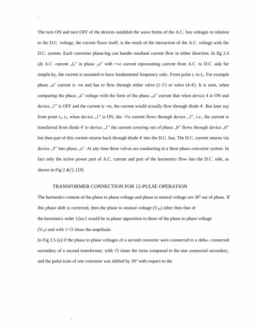
TRANSFORMER CONNECTION FOR 12-PULSE OPERATION
The harmonics content of the phase to phase voltage and phase to neutral voltage are 30º out of phase. If
this phase shift is corrected, then the phase to neutral voltage (Van) other then that of
the harmonics order 12n±1 would be in phase opposition to those of the phase to phase voltage
(Vab) and with 1/√3 times the amplitude.
In Fig 2.5 (a) if the phase to phase voltages of a second converter were connected to a delta- connected
secondary of a second transformer, with √3 times the turns compared to the star connected secondary,
and the pulse train of one converter was shifted by 30º with respect to the
-
-
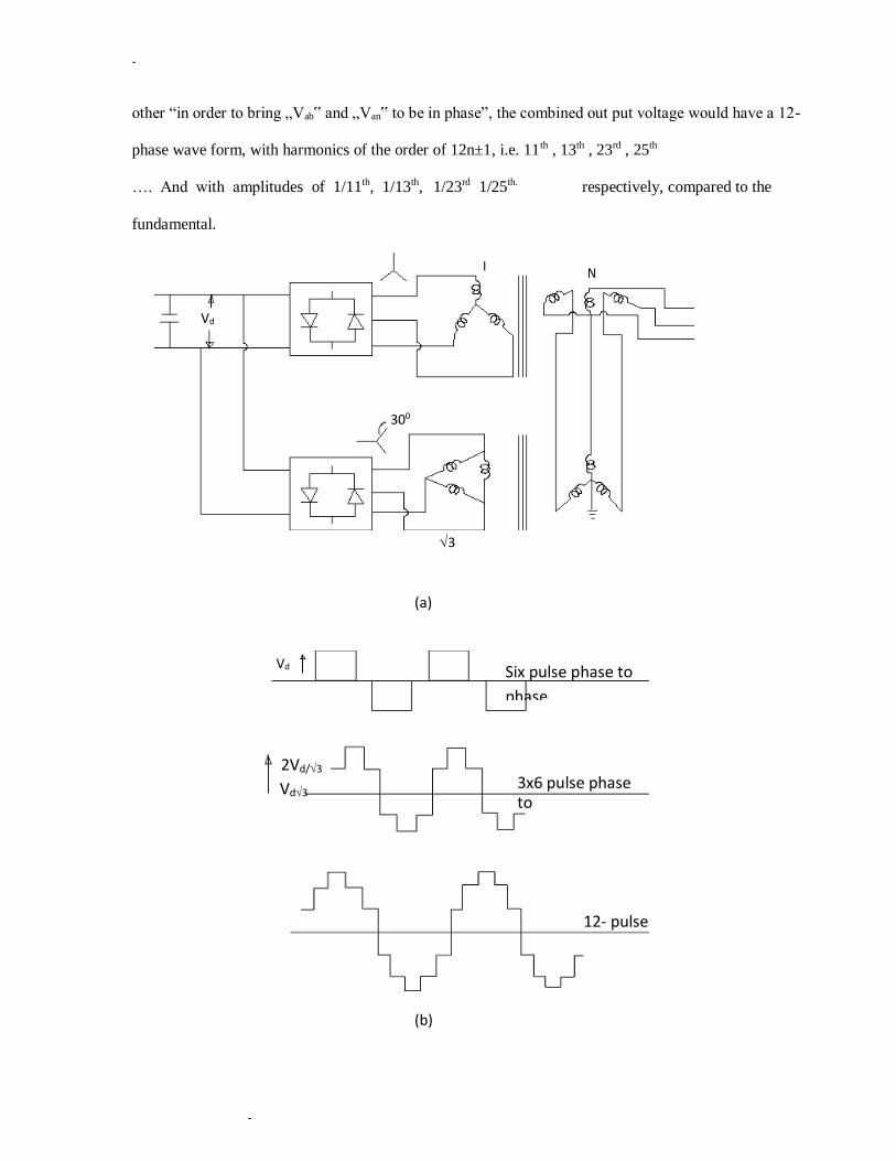
other “in order to bring „Vab‟ and „Van‟ to be in phase”, the combined out put voltage would have a 12-
phase wave form, with harmonics of the order of 12n±1, i.e. 11th , 13th , 23rd , 25th
…. And with amplitudes of 1/11th, 1/13th, 1/23rd 1/25th. respectively, compared to the
fundamental.
3
(a)
(b)
I N
Vd
300
Vd Six pulse phase to
phase
2Vd/3
Vd3 3x6 pulse phase to
„N‟
12- pulse
-
-
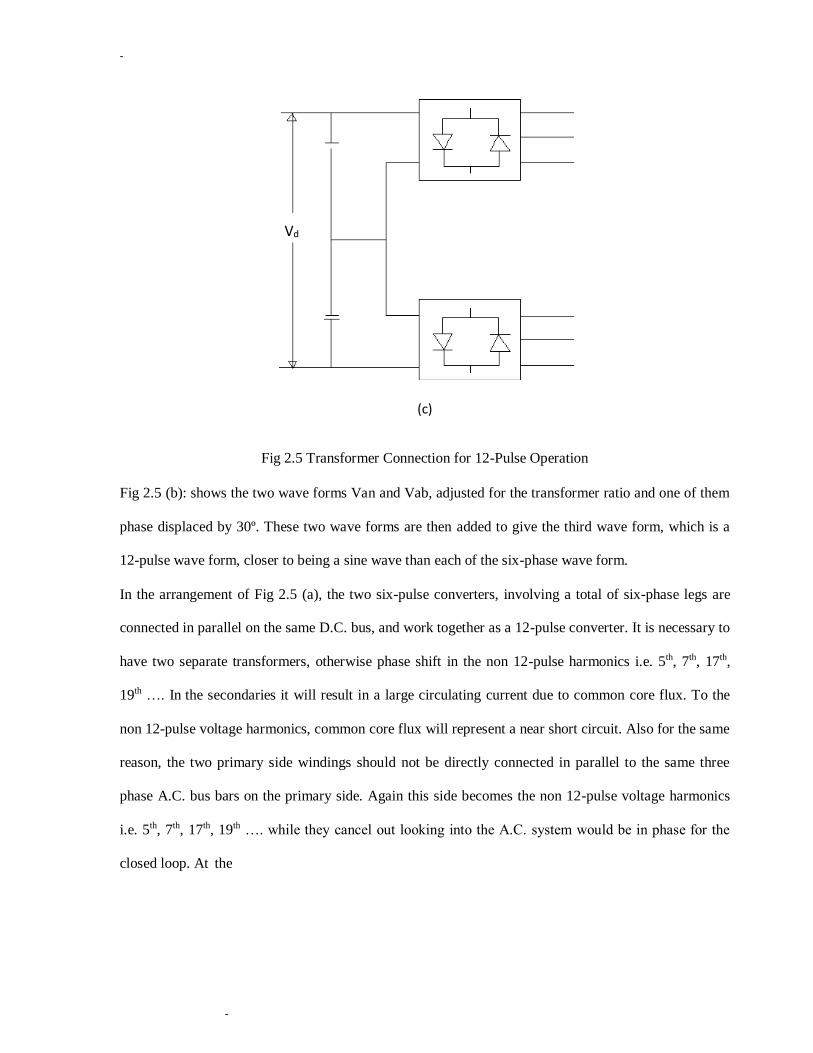
(c)
Fig 2.5 Transformer Connection for 12-Pulse Operation
Fig 2.5 (b): shows the two wave forms Van and Vab, adjusted for the transformer ratio and one of them
phase displaced by 30º. These two wave forms are then added to give the third wave form, which is a
12-pulse wave form, closer to being a sine wave than each of the six-phase wave form.
In the arrangement of Fig 2.5 (a), the two six-pulse converters, involving a total of six-phase legs are
connected in parallel on the same D.C. bus, and work together as a 12-pulse converter. It is necessary to
have two separate transformers, otherwise phase shift in the non 12-pulse harmonics i.e. 5th, 7th, 17th,
19th …. In the secondaries it will result in a large circulating current due to common core flux. To the
non 12-pulse voltage harmonics, common core flux will represent a near short circuit. Also for the same
reason, the two primary side windings should not be directly connected in parallel to the same three
phase A.C. bus bars on the primary side. Again this side becomes the non 12-pulse voltage harmonics
i.e. 5th, 7th, 17th, 19th …. while they cancel out looking into the A.C. system would be in phase for the
closed loop. At the
Vd

-
-
same time harmonics will also flow in this loop, which is essentially the leakage inductance of the
transformers.
The circulating current of each non 12-pulse harmonics is given by: In/ I1 =
100/ (XT * n²) Percent
Where I1 is the nominal fundamental current, n is the relevant harmonic number, and XT is the per unit
transformer impedance of each transformer at the fundamental frequency. For example, if XT is 0.15 per
unit at fundamental frequency, then the circulating current for the fifth harmonic will be 26.6%,
seventh, 14.9%, eleventh, 5.5%, thirteenth, 3.9%, of the rated fundamental current, and so on. Clearly
this is not acceptable for practical voltage sourced converters. Therefore, it is necessary to connect the
transformer primaries of two separate transformers in series and connect the combination to the A.C.
bus as shown in Fig 2.5 (a), with the arrangement shown in Fig 2.5 (a), the 5th, 7th, 17th, 19th….
harmonics voltages cancel out, and the two fundamental voltages add up, as shown in Fig 2.5 (b), and
the combined unit becomes a true 12-pulse converter.
TRANSFORMER CONNECTIONS FOR 24-PULSE AND 48-PULSE OPERATION
Two 12-pulse converters phase shifted by 15º from each other can provide a 24-pulse converter, with
much lower harmonics on both A.C. and D.C. sides. It‟s A.C. out put voltage would have 24n±1 order
of harmonics i.e. 23rd, 25th, 47th, 49th …. , with magnitudes of 1/23rd, 1/25th, 1/47th, 1/49th ….
respectively, of the fundamental A.C. voltage. The question now is, how to arrange this phase shift. One
approach is to provide 15º phase shift windings on the two transformers of one of the two 12-pulse
converters. Another approach is to provide phase shift windings for (+7.5º) phase shift on the two
transformers of one 12-pulse converter and (- 7.5º) on the two transformers of the other 12-pulse
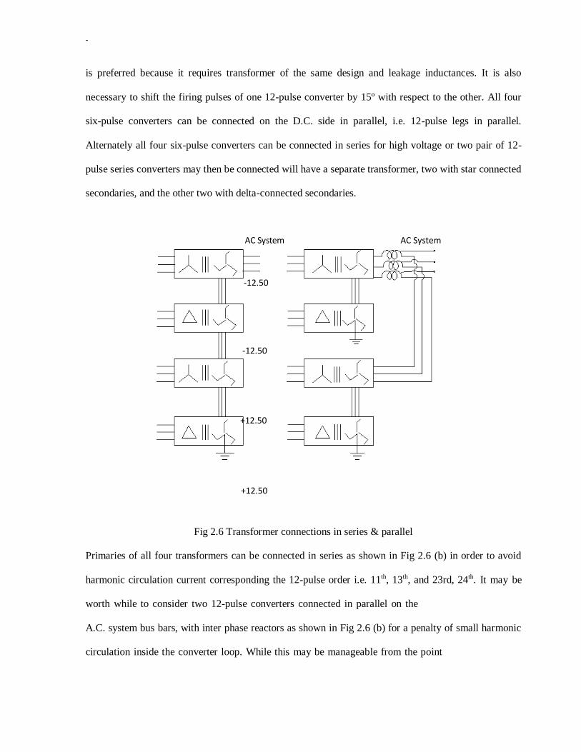
converter, as shown in Fig2.6 (a), the later
-
is preferred because it requires transformer of the same design and leakage inductances. It is also
necessary to shift the firing pulses of one 12-pulse converter by 15º with respect to the other. All four
six-pulse converters can be connected on the D.C. side in parallel, i.e. 12-pulse legs in parallel.
Alternately all four six-pulse converters can be connected in series for high voltage or two pair of 12-
pulse series converters may then be connected will have a separate transformer, two with star connected
secondaries, and the other two with delta-connected secondaries.
AC System
-12.50
AC System
-12.50
+12.50
+12.50
Fig 2.6 Transformer connections in series & parallel
Primaries of all four transformers can be connected in series as shown in Fig 2.6 (b) in order to avoid
harmonic circulation current corresponding the 12-pulse order i.e. 11th, 13th, and 23rd, 24th. It may be
worth while to consider two 12-pulse converters connected in parallel on the
A.C. system bus bars, with inter phase reactors as shown in Fig 2.6 (b) for a penalty of small harmonic
circulation inside the converter loop. While this may be manageable from the point
-
-
of view of converter rating. Care has to be taken in the design of converter controls, particularly during
light load when the harmonic currents could become the significant part of the A.C. current flowing
through the converter. As increase in the transformer impedance to say 0.2 per unit may be appropriate
when connecting two 12-pulse transformers to the A.C. bus directly and less than that when connected
through inter phase reactors. For high power FACTS Controllers, from the point of view of the A.C.
system, even a 24-pulse converter with out A.C. filters could have voltage harmonics, which are higher
then the acceptable level in this case, a single high pass filter turned to the 23rd - 25th harmonics located
on the system side of the converter transformers should be adequate.
The alternative of course, is go to 48-pulse operation with eight six pulse groups, with one set of
transformers of one 24-pulse converter phase shifted from the other by 7.5º, or one set shifted (+7.5º)
and the other by (-3.7º). Logically, all eight transformer primaries may be connected in series, but
because of the small phase shift (i.e. 7.5º) the primaries of the two 24- pulse converters each with four
primaries in series may be connected in parallel, if the consequent circulating current is accepted. This
should not be much of a problem, because the higher the order of a harmonic, the lower would be the
circulating current. For 0.1 per unit transformer impedance and the 23rd harmonic, the circulating
current can be further limited by higher transformer inductance or by inter phase reactor at the point of
parallel connection of
the two 24-pulse converters, with 48-pulse operation A.C. filters are not necessary.
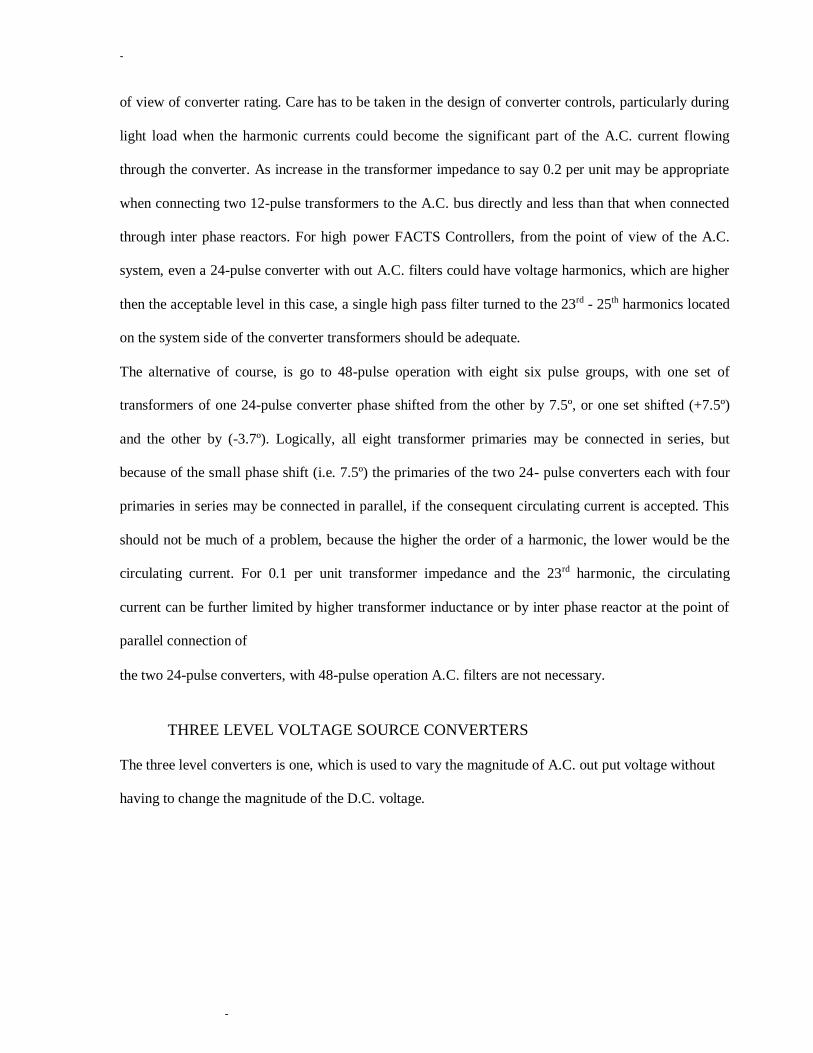
THREE LEVEL VOLTAGE SOURCE CONVERTERS
The three level converters is one, which is used to vary the magnitude of A.C. out put voltage without
having to change the magnitude of the D.C. voltage.

-
-
1 D1 11
1A 41 11A
ia
4A 41A
D4 4 41
+Vd/2
-Vd/2
(a)
1,1A 1,1A
Va-
(b)
Fig 2.7 Voltage source converters
Va +vd/2
-vd/2
1,1A
4,4A
1,1A
Va 1A,4A
4,4A
3,3A
Vb
3,3A 3,5A
Vb
+vd
+vd/2
-vd

-
-
One phase leg of a three level converter is shown in Fig 2.7 (a). The other two phase legs (not shown)
would be connected across the same D.C. bus bars and the clamping diodes connected to the same mid
point „N‟ of the D.C. capacitor. It is seen that each half of the phase leg is splitted into two series
connected valves i.e. 1-1' is Sp' into 1-1' and 1A-1'A. The mid point of the splitted valve is connected by
diodes D1 and D2 to the mid point „N‟ as shown on the phase of it; this may seen like doubling the
number of valves from two to four per phase leg, in addition to providing two extra diode valves.
However, doubling the number of valves with the same voltage rating would double the D.C. voltage
and hence the power capacity of the converter. Thus only the addition of the diode clamping valves D1
and D4 per phase leg as in Fig 2.7 (a) adds to the converter cost. If the converter is a high voltage
converter with devices in series, then the number of main devices would be about the same. A diode
clamp at the mid point may also help to ensure a more voltage sharing between the two valve halves.
Fig 2.7 (b) shows out put voltage corresponding to one three level phase leg. The first wave form shows
a full 180º square wave obtained by the closing of devices 1 and 1A to give (+Vd/2) for 180º and the
closing of valves 4 and 4A for180º to give (-Vd/2) for 180º . Now consider second voltage wave form in
Fig 2.7 (b) in which upper device 1 is OFF and device 4A is ON an angle α earlier than they were due in
the 180º square wave operation. This leaves only device 1A and 4A ON, which in combination with
diodes D1 and D2, clamp the phase voltage Va to zero with respect to the D.C. mid point „N‟ regardless
of which way the current is flowing, this continues for a period 2α until device 1A is turned OFF and
device 4 is turned ON and the voltage jumps to (-Vd/2) with both the lower devices 4 and 4A turned ON
and both the upper devices 1 and 1A turned OFF and so ON. The angle α is variable and the output
voltage Va is made up of σ = 180º - 2αº square waves. This variable period σ per half cycle allows the
-
-
voltage Va to be independently variable with a fast response. It is seen that devices 1A and 4A are turned
ON for 180º during each cycle devices 1 and 4 are turned ON for σ = 180º - 2αº during each cycle,
while diodes D1 and D4 conduct for 2αº = 180ºσ each cycle. The converter is referred to as three level
because the D.C. voltage has three levels i.e. (-Vd/2) 0 and (+Vd/2).
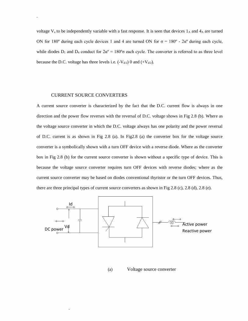
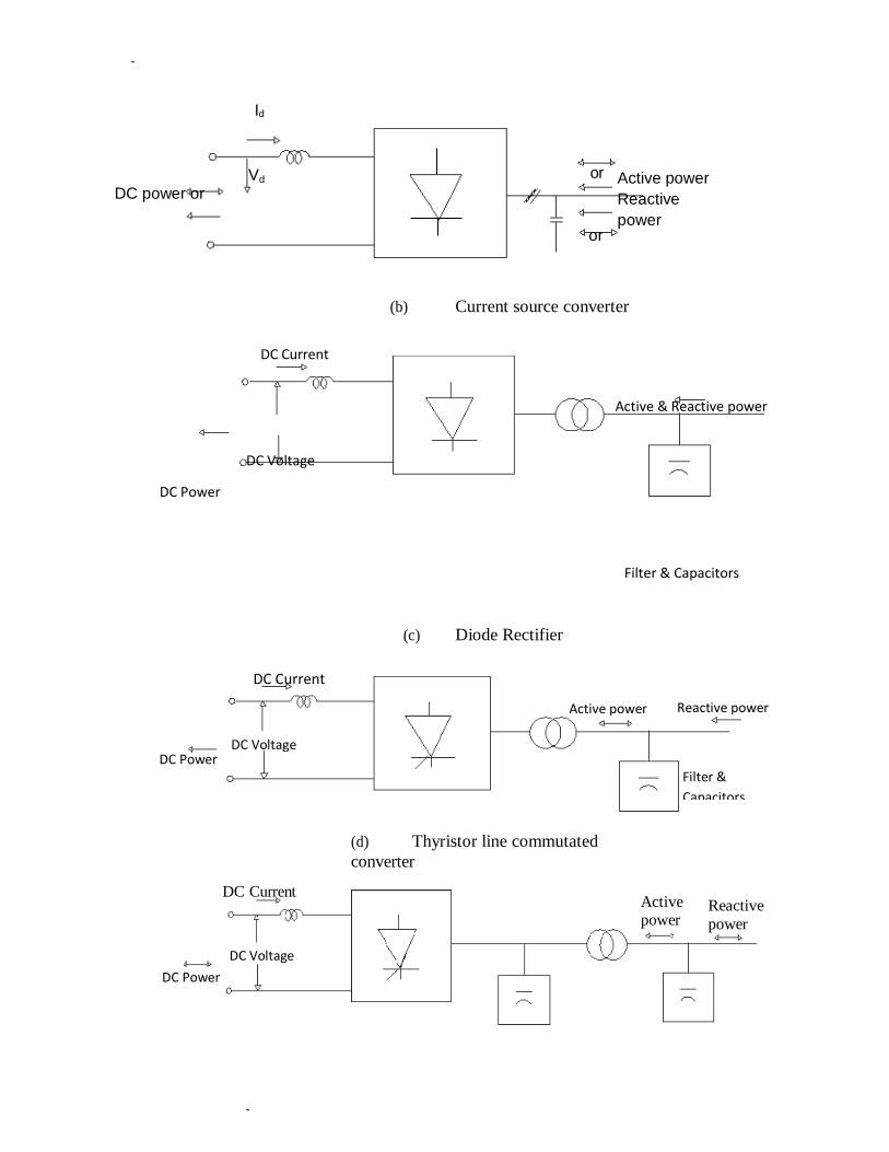
CURRENT SOURCE CONVERTERS
A current source converter is characterized by the fact that the D.C. current flow is always in one
direction and the power flow reverses with the reversal of D.C. voltage shows in Fig 2.8 (b). Where as
the voltage source converter in which the D.C. voltage always has one polarity and the power reversal
of D.C. current is as shown in Fig 2.8 (a). In Fig2.8 (a) the converter box for the voltage source
converter is a symbolically shown with a turn OFF device with a reverse diode. Where as the converter
box in Fig 2.8 (b) for the current source converter is shown without a specific type of device. This is
because the voltage source converter requires turn OFF devices with reverse diodes; where as the
current source converter may be based on diodes conventional thyristor or the turn OFF devices. Thus,
there are three principal types of current source converters as shown in Fig 2.8 (c), 2.8 (d), 2.8 (e).
Id
DC power Vd
Active power
Reactive power
(a) Voltage source converter
-
-
DC power or
Id
Vd or
or
Active power
Reactive
power
(b) Current source converter
DC Current
Active & Reactive power
DC Voltage
DC Power
Filter & Capacitors
(c) Diode Rectifier
DC Power
DC Current
DC Voltage
(d) Thyristor line commutated
converter
Active power
Reactive
power
DC Current
Active power Reactive power
DC Voltage DC Power
Filter &
Capacitors

-
-
(e) Self commutated converters
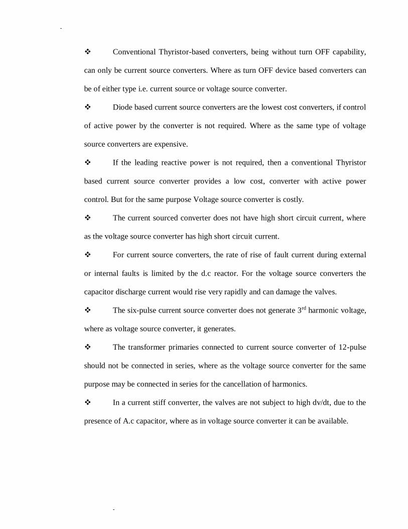
Fig 2.8 (c) represents the diode converter, which simply converts A.C. voltage to D.C. voltage and
utilizes A.C. system voltage for commutating of D.C. current from one valve to another. Obviously
the diode based line commutating converter just converts A.C. power to D.C. power without any
control and also in doing so consumes some reactive power on the A.C. side. Thyristor Line
Commutated ConverterIt is based on conventional thyristor with gate turn ON but without gate turn
OFF capability as in Fig 2.8 (d): utilizes A.C. system voltage for commutation of current from one
valve to another. This converter can convert and controls active power in either direction, but in doing
so consumes reactive power on the A.C. side. It can not supply reactive power to the A.C. system. Self
Commutated Converter It is based on turn OFF devices like (GTOs, MTOs, IGBTs, etc) in which
commutation of current from valve to valve takes place with the device turn OFF action and provision
of A.C. capacitors to facilitate transfer of current from valve to valve as in Fig 2.8 (e).Where as in a
voltage source converter the commutation of current is supported by a stiff D.C. bus with D.C.
capacitors provide a stiff A.C. bus for supplying the fact changing current pulses needed for the
commutations. It also supplies or consumes the reactive power.
Comparison between Current Source Converters and Voltage Source Converters
Current source converters in which direct current always has one polarity and
the power reversal takes place through reversal of D.C. voltage polarity. Where as
voltage source converters in which the D.C. voltage always has one polarity, and the
power reversal takes place through reversal of D.C. current polarity.
-
-
Conventional Thyristor-based converters, being without turn OFF capability,
can only be current source converters. Where as turn OFF device based converters can
be of either type i.e. current source or voltage source converter.
Diode based current source converters are the lowest cost converters, if control
of active power by the converter is not required. Where as the same type of voltage
source converters are expensive.
If the leading reactive power is not required, then a conventional Thyristor
based current source converter provides a low cost, converter with active power
control. But for the same purpose Voltage source converter is costly.
The current sourced converter does not have high short circuit current, where
as the voltage source converter has high short circuit current.
For current source converters, the rate of rise of fault current during external
or internal faults is limited by the d.c reactor. For the voltage source converters the
capacitor discharge current would rise very rapidly and can damage the valves.
The six-pulse current source converter does not generate 3rd harmonic voltage,
where as voltage source converter, it generates.
The transformer primaries connected to current source converter of 12-pulse
should not be connected in series, where as the voltage source converter for the same
purpose may be connected in series for the cancellation of harmonics.
In a current stiff converter, the valves are not subject to high dv/dt, due to the
presence of A.c capacitor, where as in voltage source converter it can be available.
A.C capacitors required for the current stiff converters can be quite large and
expensive, where as voltage source converter used small size of capacitors which are
cheap.
Continuous losses in the d.c reactor of a current source converter are much
higher than the losses in the d.c capacitor, where as in voltage source converter they are
relaxable.[23]

UNIT-III
STATIC SHUNT COMPENSATORS
Objectives of shunt compensation –methods of controllable VAR generation-static VAR
compensators, SVC and STATCOM, comparison
****************
OBJECTIVES OF SHUNT COMPENSATION:
Shunt compensation is used to influence the natural characteristics of the transmission line to “ steady-state transmittable power
and to control voltage profile along the line” shunt connected fixed or mechanically switched reactors are used to minimize line
over-voltage under light load conditions. Shunt connected fixed or mechanically switched capacitors are applied to maintain
voltage levels under heavy load conditions.
Var compensation is used for voltage regulation.
i. At the midpoint to segment the transmission line and
ii. At the end of the line
To prevent “voltage intangibility as well as for dynamic voltage control to increase transient stability and to damp out power
oscillations”.
MID-POINT VOLTAGE REGULATION FOR LINE SEGMENTATION:
Consider simple two-machine(two-bus)transmission model in which an ideal var compensator is shunt connected at the
midpoint of the transmission line
FIG:


NOTE:
i. The midpoint of the transmission line is the best location for compensator because the voltage sage along the
uncompensated transmission line is the longest at the midpoint
ii. The concept of transmission line segmentation can be expanded to use of multiple compensators, located at
equal segments of the transmission line as shown in fig.
END OF LINE VOLTAGE TO SUPPORT TO PREVENT VOLTAGE INSTABILITY:
A simple radial system with feeder line reactance X and load impedance Z is shown.
NOTE:
1. For a radial line , the end of the line, where the largest voltage variation is experienced, is the best location for
the compensator.
2. Reactive shunt compensation is often used too regulate voltage support for the load when capacity of sending –
end system becomes impaired.
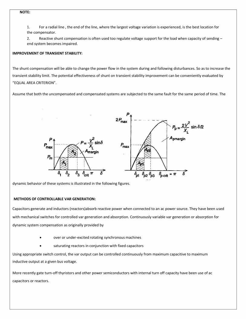
IMPROVEMENT OF TRANSIENT STABILITY:
The shunt compensation will be able to change the power flow in the system during and following disturbances. So as to increase the
transient stability limit. The potential effectiveness of shunt on transient stability improvement can be conveniently evaluated by
“EQUAL AREA CRITERION”.
Assume that both the uncompensated and compensated systems are subjected to the same fault for the same period of time. The
dynamic behavior of these systems is illustrated in the following figures.
METHODS OF CONTROLLABLE VAR GENERATION:
Capacitors generate and inductors (reactors)absorb reactive power when connected to an ac power source. They have been used
with mechanical switches for controlled var generation and absorption. Continuously variable var generation or absorption for
dynamic system compensation as originally provided by
over or under-excited rotating synchronous machines
saturating reactors in conjunction with fixed capacitors
Using appropriate switch control, the var output can be controlled continuously from maximum capacitive to maximum
inductive output at a given bus voltage.
More recently gate turn-off thyristors and other power semiconductors with internal turn off capacity have been use of ac
capacitors or reactors.


It is evident that the magnitude of current in the reactor can be varied continuously by the method of delay angle control from
maximum (α=0) to zero (α=90).
In practice, the maximum magnitude of the applied voltage and that of the corresponding current will be limited by the ratings of the
power components(reactor and thyristor valve)used. Thus, a practical TCR can be operated anywhere in a defined V-I area ,the
boundaries of which are determined by its maximum attainable admittance, voltage and current ratings are shown in fig.
Note: If Thyristor Controlled Reactor(TCR) switching is restricted to a fixed delay angle, usually α=0, then it becomes a thyristors –
switched reactor (TSR). The TSR provides a fixed inductive admittance. Thus, when connected to the a.c. system, the reactive current
in it will be proportional to the applied voltage as shown in fig.
TSRs can provide at α=0, the resultant steady-state current will be sinusoidal.

THYRISTOR SWITCHED CAPACITOR(TSC):
A single-phase thyristors switched capacitor (TSC) is shown in fig.
It consists of a capacitor, a bi-directional thyristors valve, and a relatively small surge current limiting reactor. This reactor is
needed primarily
To limit the surge current in the thyristors valve under abnormal operating conditions To avoid
resonances with the a.c. system impedance at particular frequencies
Under steady state conditions, when the thyristor valve is closed and the TSC branch is connected to a sinusoidal a.c. voltage source,
υ=Vsin ωt, the current in the branch is given by
The TSC branch can be disconnected (“switched out”) at any current zero by prior removal of the gate drive to the thyristor valve.
At the current zero crossing, the capacitor voltage is at its peak valve. The disconnected capacitor stays charged to this voltage, and
consequently the voltage across the non-conducting thyristors valve varied between zero and the peak-to-peak value of the
applied a.c. voltage as shown in fig.(b).

The TSC branch represents a single capacitive admittance which is either connected to, or disconnected from the a.c. system. The
current in the TSC branch varies linearly with the applied voltage according to the admittance of the capacitor as illustrated by the V-I
plot in the following fig.
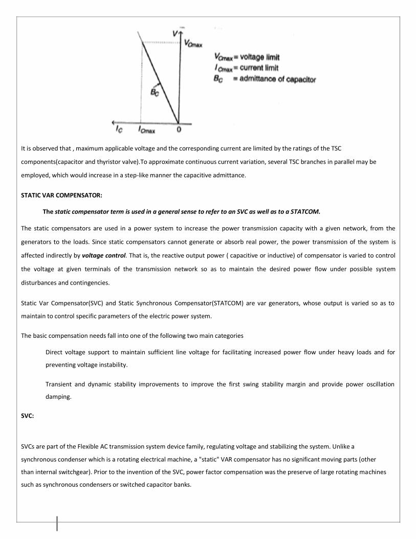
It is observed that , maximum applicable voltage and the corresponding current are limited by the ratings of the TSC
components(capacitor and thyristor valve).To approximate continuous current variation, several TSC branches in parallel may be
employed, which would increase in a step-like manner the capacitive admittance.
STATIC VAR COMPENSATOR:
The static compensator term is used in a general sense to refer to an SVC as well as to a STATCOM.
The static compensators are used in a power system to increase the power transmission capacity with a given network, from the
generators to the loads. Since static compensators cannot generate or absorb real power, the power transmission of the system is
affected indirectly by voltage control. That is, the reactive output power ( capacitive or inductive) of compensator is varied to control
the voltage at given terminals of the transmission network so as to maintain the desired power flow under possible system
disturbances and contingencies.
Static Var Compensator(SVC) and Static Synchronous Compensator(STATCOM) are var generators, whose output is varied so as to
maintain to control specific parameters of the electric power system.
The basic compensation needs fall into one of the following two main categories
Direct voltage support to maintain sufficient line voltage for facilitating increased power flow under heavy loads and for
preventing voltage instability.
Transient and dynamic stability improvements to improve the first swing stability margin and provide power oscillation
damping.
SVC:
SVCs are part of the Flexible AC transmission system device family, regulating voltage and stabilizing the system. Unlike a
synchronous condenser which is a rotating electrical machine, a "static" VAR compensator has no significant moving parts (other
than internal switchgear). Prior to the invention of the SVC, power factor compensation was the preserve of large rotating machines
such as synchronous condensers or switched capacitor banks.

Fig.shows Static Var Compensator(SVC).
An SVC comprises one or more banks of fixed or switched shunt capacitors or reactors, of which at least one bank is switched by
thyristors. Elements which may be used to make an SVC typically include:
Thyristor controlled reactor (TCR), where the reactor may be air- or iron-cored Thyristor
switched capacitor (TSC)
Harmonic filter(s)
Mechanically switched capacitors or reactors (switched by a circuit breaker)
The SVC is an automated impedance matching device, designed to bring the system closer to unity power factor. SVCs are used in
two main situations:
Connected to the power system, to regulate the transmission voltage ("Transmission SVC") Connected near
large industrial loads, to improve power quality ("Industrial SVC")
Fig.shows V-I Characteristics of SVC.

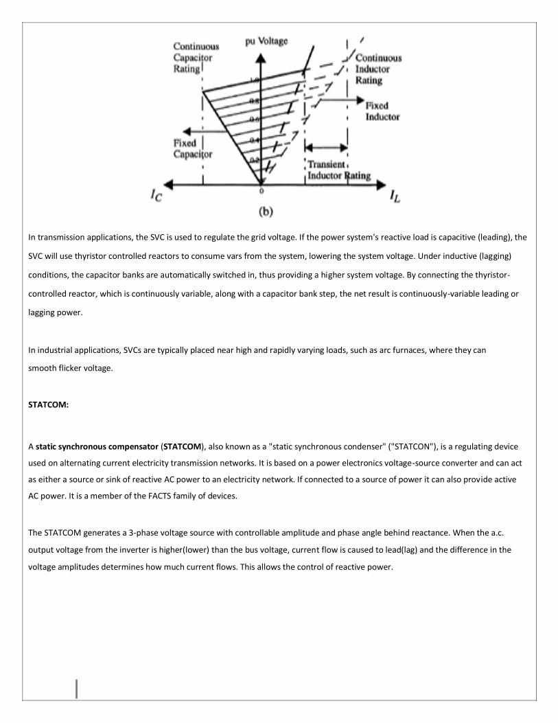
In transmission applications, the SVC is used to regulate the grid voltage. If the power system's reactive load is capacitive (leading), the
SVC will use thyristor controlled reactors to consume vars from the system, lowering the system voltage. Under inductive (lagging)
conditions, the capacitor banks are automatically switched in, thus providing a higher system voltage. By connecting the thyristor-
controlled reactor, which is continuously variable, along with a capacitor bank step, the net result is continuously-variable leading or
lagging power.
In industrial applications, SVCs are typically placed near high and rapidly varying loads, such as arc furnaces, where they can
smooth flicker voltage.
STATCOM:
A static synchronous compensator (STATCOM), also known as a "static synchronous condenser" ("STATCON"), is a regulating device
used on alternating current electricity transmission networks. It is based on a power electronics voltage-source converter and can act
as either a source or sink of reactive AC power to an electricity network. If connected to a source of power it can also provide active
AC power. It is a member of the FACTS family of devices.
The STATCOM generates a 3-phase voltage source with controllable amplitude and phase angle behind reactance. When the a.c.
output voltage from the inverter is higher(lower) than the bus voltage, current flow is caused to lead(lag) and the difference in the
voltage amplitudes determines how much current flows. This allows the control of reactive power.

Fig. shows block diagram representation of STATCOM and V-I characteristics.
The STATCOM is implemented by a 6-pulse Voltage Source Inverter(VSI) comprising GTO thyristors fed from a d.c.storage
capacitor.The STATCOM is able to control its output current over the rated maximum capacitive or inductive range independently of
a.c. system voltage, in contrast to the SVC that varies with the ac system voltage. Thus STATCOM is more effective than the SVC in
providing voltage support and stability improvements. The STATCOM can continue to produce capacitive current independent of
voltage.The amount and duration of the overload capability is dependent upon the thermal capacity of the GTO.
Note : Multi-pulse circuit configurations are employed to reduce the harmonic generation and to produce practically
sinusoidal current.
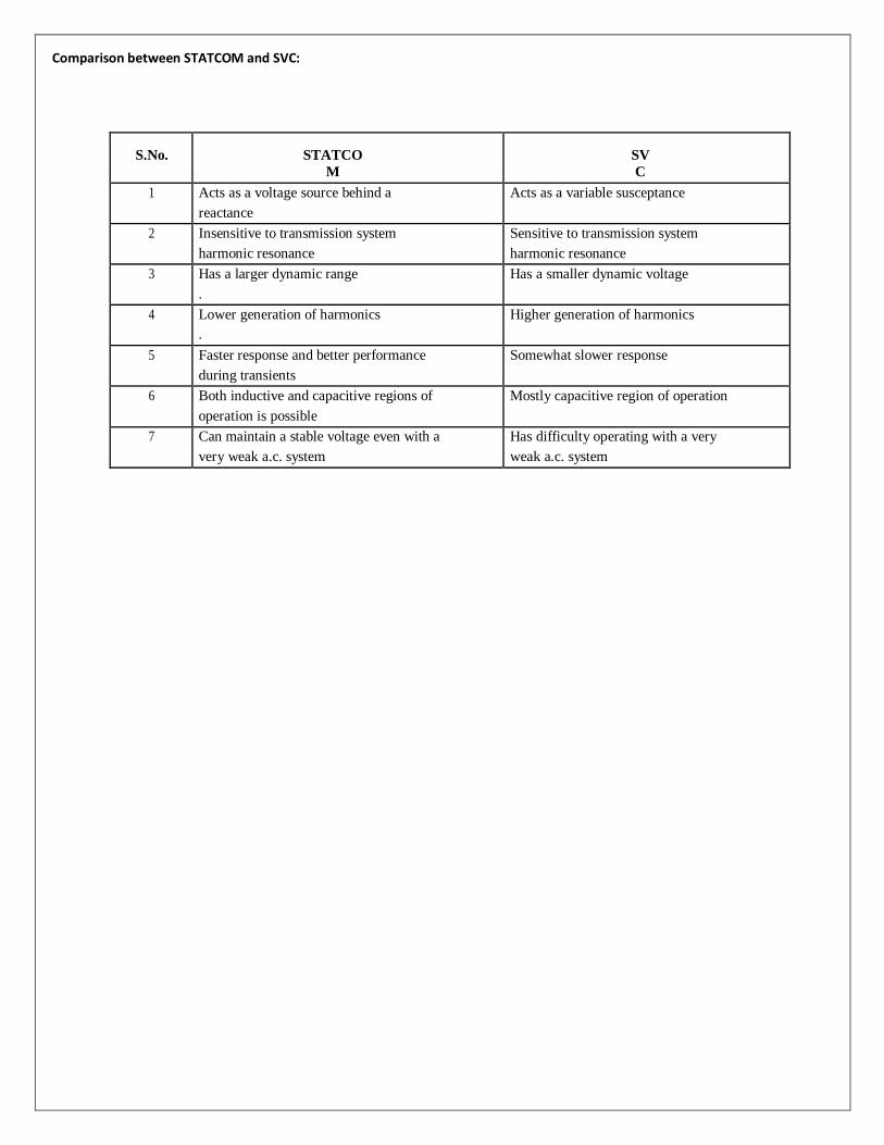
Comparison between STATCOM and SVC:
S.No.
STATCO
M
SV
C
1 Acts as a voltage source behind a
reactance
Acts as a variable susceptance
2 Insensitive to transmission system
harmonic resonance
Sensitive to transmission system
harmonic resonance
3 Has a larger dynamic range
.
Has a smaller dynamic voltage
4 Lower generation of harmonics
.
Higher generation of harmonics
5 Faster response and better performance
during transients
Somewhat slower response
6 Both inductive and capacitive regions of
operation is possible
Mostly capacitive region of operation
7 Can maintain a stable voltage even with a
very weak a.c. system
Has difficulty operating with a very
weak a.c. system

UNIT-IV
STATIC SYNCHRONOUS SERIES COMPENSATOR
INTRODUCTION
Series compensation is a means of controlling the power transmitted across transmission
lines by altering or changing the characteristic impedance of the line. The power flow
problem may be related to the length of the transmission line. The transmission line may
be compensated by a fixed capacitor or inductor to meet the requirements of the
transmission system. When the structure of the transmission network is considered,
power flow imbalance problems arise. Inadvertent interchange occurs when the power
system tie line becomes corrupted. This is because of unexpected change in load on a
distribution feeder due to which the demand for power on that feeder increases or
decreases. The generators are to be turned on or off to compensate for this change in
load. If the generators are not activated very quickly, voltage sags or surges can occur.
In such cases, controlled series compensation helps effectively.
SERIES COMPENSATOR
Series compensation, if properly controlled, provides voltage stability and transient
stability improvements significantly for post-fault systems. It is also very effective in
damping out power oscillations and mitigation of sub-synchronous resonance
(Hingorani 2000).
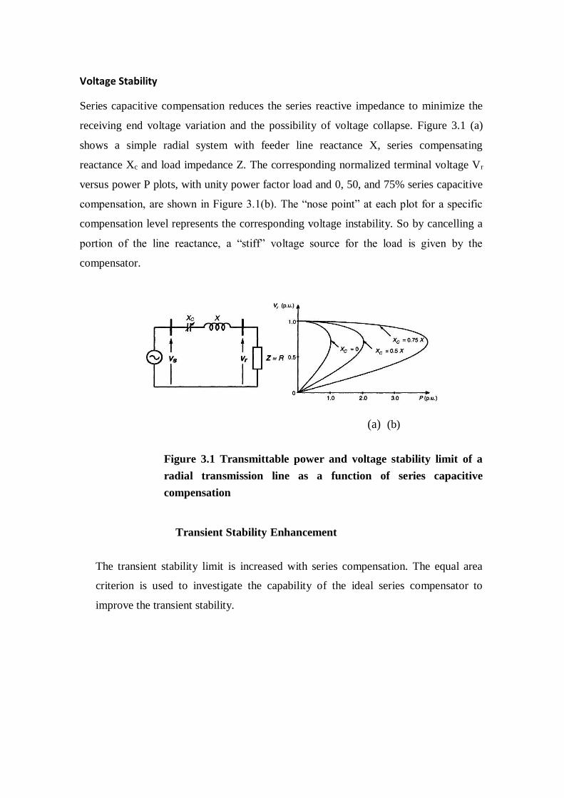
Voltage Stability
Series capacitive compensation reduces the series reactive impedance to minimize the
receiving end voltage variation and the possibility of voltage collapse. Figure 3.1 (a)
shows a simple radial system with feeder line reactance X, series compensating
reactance Xc and load impedance Z. The corresponding normalized terminal voltage Vr
versus power P plots, with unity power factor load and 0, 50, and 75% series capacitive
compensation, are shown in Figure 3.1(b). The “nose point” at each plot for a specific
compensation level represents the corresponding voltage instability. So by cancelling a
portion of the line reactance, a “stiff” voltage source for the load is given by the
compensator.
(a) (b)
Figure 3.1 Transmittable power and voltage stability limit of a
radial transmission line as a function of series capacitive
compensation
Transient Stability Enhancement
The transient stability limit is increased with series compensation. The equal area
criterion is used to investigate the capability of the ideal series compensator to
improve the transient stability.

Figure 3.2 Two machine system with series capacitive compensation
Figure 3.2 shows the simple system with the series compensated line. Assumptions
that are made here are as follows:
• The pre-fault and post-fault systems remain the same for the
series compensated system.
• The system, with and without series capacitive compensation,
transmits the same power Pm.
• Both the uncompensated and the series compensated systems are
subjected to the same fault for the same period of time.
Figures 3.3 (a) and (b) show the equal area criterion for a simple two machine
system without and with series compensator for a three phase to ground fault in the
transmission line. From the figures, the dynamic behaviour of these systems are
discussed.
Prior to the fault, both of them transmit power Pm at angles 61 and 6s1 respectively.
During the fault, the transmitted electric power becomes zero, while the mechanical
input power to the generators remains constant (Pm). Hence, the sending end
generator accelerates from the steady-state angles 61 and 6s1 to 62 and 6s2
respectively, when the fault clears. In the figures, the accelerating energies are
represented by areas A1 and As1. After fault clearing, the transmitted electric
power exceeds the mechanical input
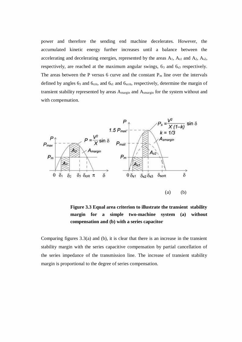
power and therefore the sending end machine decelerates. However, the
accumulated kinetic energy further increases until a balance between the
accelerating and decelerating energies, represented by the areas A1, As1 and A2, As2,
respectively, are reached at the maximum angular swings, 63 and 6s3 respectively.
The areas between the P versus 6 curve and the constant Pm line over the intervals
defined by angles 63 and 6crit, and 6s1 and 6scrit, respectively, determine the margin of
transient stability represented by areas Amargin and Asmargin for the system without and
with compensation.
(a) (b)
Figure 3.3 Equal area criterion to illustrate the transient stability
margin for a simple two-machine system (a) without
compensation and (b) with a series capacitor
Comparing figures 3.3(a) and (b), it is clear that there is an increase in the transient
stability margin with the series capacitive compensation by partial cancellation of
the series impedance of the transmission line. The increase of transient stability
margin is proportional to the degree of series compensation.
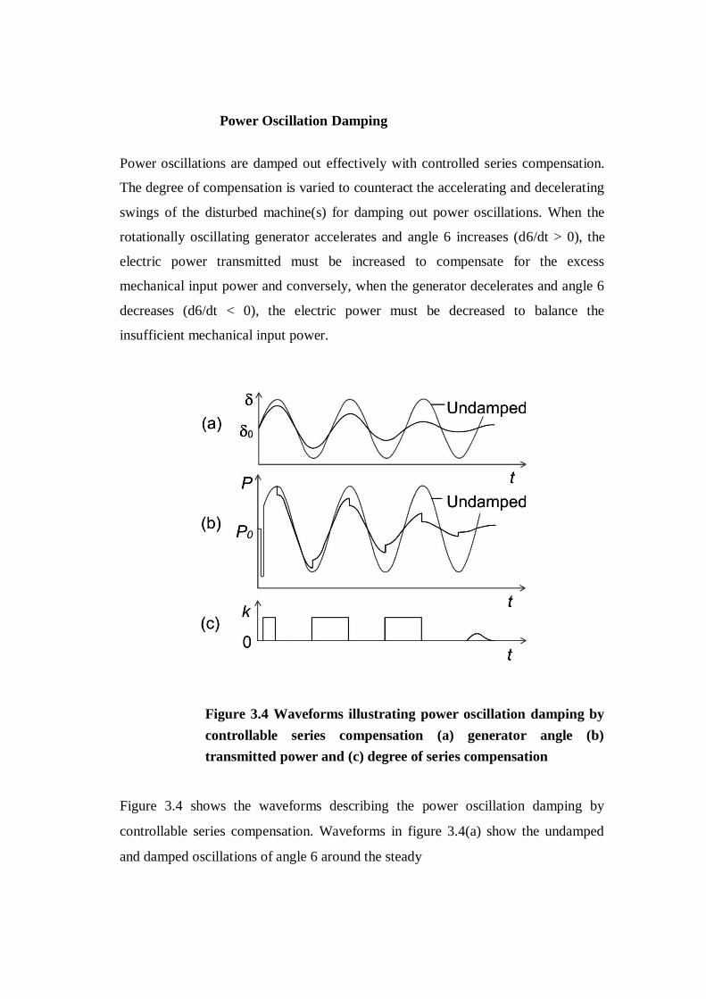
Power Oscillation Damping
Power oscillations are damped out effectively with controlled series compensation.
The degree of compensation is varied to counteract the accelerating and decelerating
swings of the disturbed machine(s) for damping out power oscillations. When the
rotationally oscillating generator accelerates and angle 6 increases (d6/dt > 0), the
electric power transmitted must be increased to compensate for the excess
mechanical input power and conversely, when the generator decelerates and angle 6
decreases (d6/dt < 0), the electric power must be decreased to balance the
insufficient mechanical input power.
Figure 3.4 Waveforms illustrating power oscillation damping by
controllable series compensation (a) generator angle (b)
transmitted power and (c) degree of series compensation
Figure 3.4 shows the waveforms describing the power oscillation damping by
controllable series compensation. Waveforms in figure 3.4(a) show the undamped
and damped oscillations of angle 6 around the steady
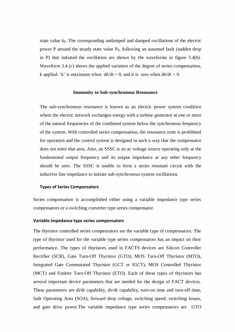
state value 60. The corresponding undamped and damped oscillations of the electric
power P around the steady state value P0, following an assumed fault (sudden drop
in P) that initiated the oscillation are shown by the waveforms in figure 3.4(b).
Waveform 3.4 (c) shows the applied variation of the degree of series compensation,
k applied. ‘k’ is maximum when d6/dt > 0, and it is zero when d6/dt < 0.
Immunity to Sub-synchronous Resonance
The sub-synchronous resonance is known as an electric power system condition
where the electric network exchanges energy with a turbine generator at one or more
of the natural frequencies of the combined system below the synchronous frequency
of the system. With controlled series compensation, the resonance zone is prohibited
for operation and the control system is designed in such a way that the compensator
does not enter that area. Also, an SSSC is an ac voltage source operating only at the
fundamental output frequency and its output impedance at any other frequency
should be zero. The SSSC is unable to form a series resonant circuit with the
inductive line impedance to initiate sub-synchronous system oscillations.
Types of Series Compensators
Series compensation is accomplished either using a variable impedance type series
compensators or a switching converter type series compensator.
Variable impedance type series compensators
The thyristor controlled series compensators are the variable type of compensators. The
type of thyristor used for the variable type series compensators has an impact on their
performance. The types of thyristors used in FACTS devices are Silicon Controller
Rectifier (SCR), Gate Turn-Off Thyristor (GTO), MOS Turn-Off Thyristor (MTO),
Integrated Gate Commutated Thyristor (GCT or IGCT), MOS Controlled Thyristor
(MCT) and Emitter Turn-Off Thyristor (ETO). Each of these types of thyristors has
several important device parameters that are needed for the design of FACT devices.
These parameters are di/dt capability, dv/dt capability, turn-on time and turn-off time,
Safe Operating Area (SOA), forward drop voltage, switching speed, switching losses,
and gate drive power.The variable impedance type series compensators are GTO

thyristor controlled series compensator (GCSC), Thyristor Switched Series Capacitor
(TSSC) and Thyristor Controlled Series Capacitor (TCSC).
GTO Thyristor Controlled Series Capacitor (GCSC)
A GCSC consists of a fixed capacitor in parallel with a GTO Thyristor as in figure
3.5which has the ability to be turned on or off. The GCSC controls the voltage across
the capacitor (Vc) for a given line current. In other words, when the GTO is closed the
voltage across the capacitor is zero and when the GTO is open the voltage across the
capacitor is at its maximum value. The magnitude of the capacitor voltage can be varied
continuously by the method of delayed angle control (max y = 0, zero y = n/2). For
practical applications, the GCSC compensates either the voltage or reactance.
Figure 3.5 GTO Controlled Series Capacitor
Thyristor Switched Series Capacitor (TSSC)
Thyristor Switched Series Capacitor (TSSC) is another type of variable impedance
type series compensators shown in Figure 3.6. The TSSC consists of several
capacitors shunted by a reverse connected thyristor bypass switch.
Figure 3.6 Thyristor Switched Series Capacitor
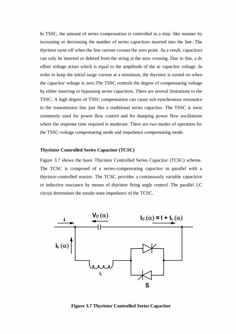
In TSSC, the amount of series compensation is controlled in a step- like manner by
increasing or decreasing the number of series capacitors inserted into the line. The
thyristor turns off when the line current crosses the zero point. As a result, capacitors
can only be inserted or deleted from the string at the zero crossing. Due to this, a dc
offset voltage arises which is equal to the amplitude of the ac capacitor voltage. In
order to keep the initial surge current at a minimum, the thyristor is turned on when
the capacitor voltage is zero.The TSSC controls the degree of compensating voltage
by either inserting or bypassing series capacitors. There are several limitations to the
TSSC. A high degree of TSSC compensation can cause sub-synchronous resonance
in the transmission line just like a traditional series capacitor. The TSSC is most
commonly used for power flow control and for damping power flow oscillations
where the response time required is moderate. There are two modes of operation for
the TSSC-voltage compensating mode and impedance compensating mode.
Thyristor Controlled Series Capacitor (TCSC)
Figure 3.7 shows the basic Thyristor Controlled Series Capacitor (TCSC) scheme.
The TCSC is composed of a series-compensating capacitor in parallel with a
thyristor-controlled reactor. The TCSC provides a continuously variable capacitive
or inductive reactance by means of thyristor firing angle control. The parallel LC
circuit determines the steady-state impedance of the TCSC.
Figure 3.7 Thyristor Controlled Series Capacitor

The impedance of the controllable reactor is varied from its maximum
(infinity) to its minimum (mL). The TCSC has two operating ranges; one is when
aClim ≤ a ≤ n/2, where the TCSC is in capacitive mode. The other range of operation
is 0 ≤ a ≤ aLlim, where the TCSC is in inductive mode. TCSC can be operated in
impedance compensation mode or voltage compensation mode
Switching converter type compensator
With the high power forced-commutated valves such as the GTO and
ETO, the converter-based FACTS controllers have become true. The advantages of
converter-based FACTS controllers are continuous and precise power control, cost
reduction of the associated relative components and a reduction in size and weight of
the overall system.
An SSSC is an example of a FACTS device that has its primary function
to change the characteristic impedance of the transmission line and thus change the
power flow. The impedance of the transmission line is changed by injecting a
voltage which leads or lags the transmission line current by 90º.
Figure 3.8 Schematic diagram of SSSC

If the SSSC is equipped with an energy storage system, the SSSC gets an
added advantage of real and reactive power compensation in the power system. By
controlling the angular position of the injected voltage with respect to the line
current, the real power is provided by the SSSC with energy storage element. Figure
3.8 shows a schematic diagram of SSSC with energy storage system for real and
reactive power exchange.The applications for an SSSC are the same as for
traditional controllable series capacitors. The SSSC is used for power flow control,
voltage stability and phase angle stability. The benefit of the SSSC over the
conventional controllable series capacitor is that the SSSC induces both capacitive
and inductive series compensating voltages on a line. Hence, the SSSC has a wider
range of operation compared with the traditional series capacitors.The primary
objective of this thesis is to examine the possible uses of the SSSC with energy
storage system with state-of-the-art power semiconductor devices in order to provide
a more cost effective solution.
Comparison of Series Compensator Types
Figure 3.9 shows a comparison of VI and loss characteristics of variable
type series compensators and the converter based series compensator.
Figure 3.9 Comparison of Variable Type Series Compensators to
Converter Type Series Compensator

From the figure the following conclusions can be made.
• The SSSC is capable of internally generating a controllable
compensating voltage over any capacitive or inductive range
independent of the magnitude of the line current. The GCSC and
the TSSC generate a compensating voltage that is proportional to
the line current. The TCSC maintains the maximum compensating
voltage with decreasing line current but the control range of the
compensating voltage is determined by the current boosting
capability of the thyristor controlled reactor.
• The SSSC has the ability to be interfaced with an external dc power
supply. The external dc power supply is used to provide
compensation for the line resistance. This is accomplished by the
injection of real power as well as for the line reactance by the
injection of reactive power. The variable impedance type series
compensators cannot inject real power into the transmission line.
They can only provide reactive power compensation.
• The SSSC with energy storage can increase the effectiveness of the
power oscillation damping by modulating the amount of series
compensation in order to increase or decrease the transmitted
power. The SSSC increases or decreases the amount of transmitted
power by injecting positive and negative real impedances into the
transmission line. The variable-type series compensators can damp
the power oscillations by modulating the reactive compensation.
STATIC SYNCHRONOUS SERIES COMPENSATOR (SSSC)
The Voltage Sourced Converter (VSC) based series compensators - Static
Synchronous Series Compensator (SSSC) was proposed by Gyugyi in 1989. The
single line diagram of a two machine system with SSSC is shown in Figure 3.10.
The SSSC injects a compensating voltage in series with the

line irrespective of the line current. From the phasor diagram, it can be stated that at
a given line current, the voltage injected by the SSSC forces the opposite polarity
voltage across the series line reactance. It works by increasing the voltage across the
transmission line and thus increases the corresponding line current and transmitted
power.
Figure 3.10 Simplified diagram of series compensation with the phasor diagram.
The compensating reactance is defined to be negative when the SSSC is
operated in an inductive mode and positive when operated in capacitive mode. The
voltage source converter can be controlled in such a way that the output voltage can
either lead or lag the line current by 90o. During normal capacitive compensation,
the output voltage lags the line current by 90o. The SSSC can increase or decrease
the power flow to the same degree in either direction simply by changing the
polarity of the injected ac voltage. The reversed (180o) phase shifted voltage adds
directly to the reactive voltage drop of the line. The reactive line impedance appears
as if it were increased. If the amplitude of the reversed polarity voltage is large
enough, the power flow will be reversed. The transmitted power verses transmitted
phase angle relationship is shown in Equation (3.1) and the transmitted power verses
transmitted angle as a function of the degree of series compensation is shown in
Figure 3.11.
V2 V ð
P = sin ð + X X
Vq cos 2
(3.1)
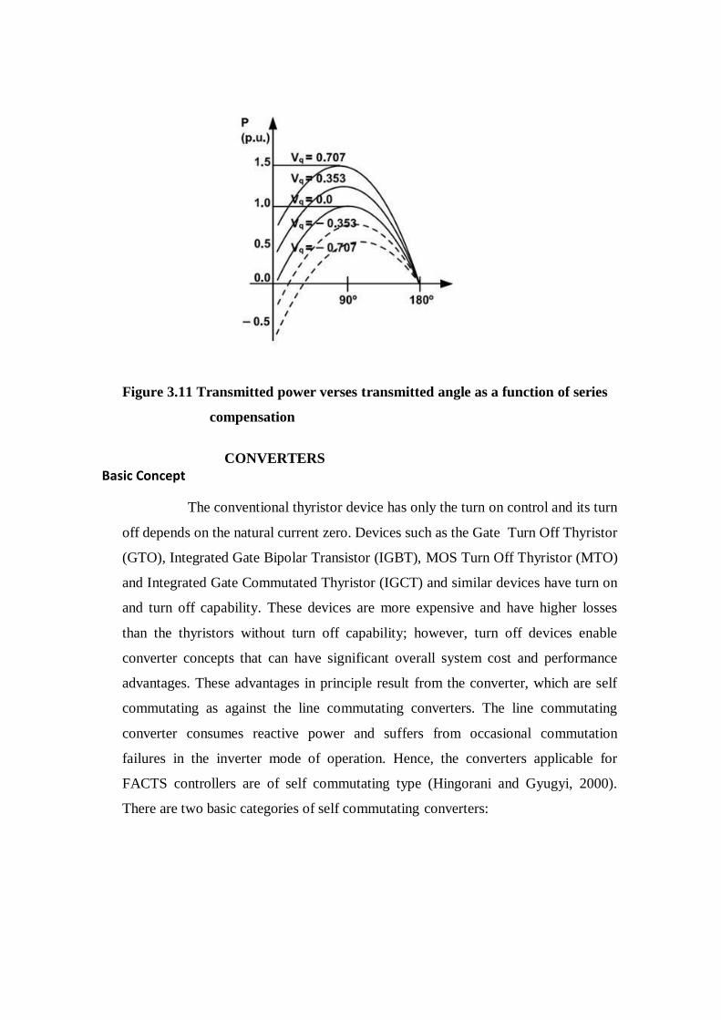
Figure 3.11 Transmitted power verses transmitted angle as a function of series
compensation
CONVERTERS
Basic Concept
The conventional thyristor device has only the turn on control and its turn
off depends on the natural current zero. Devices such as the Gate Turn Off Thyristor
(GTO), Integrated Gate Bipolar Transistor (IGBT), MOS Turn Off Thyristor (MTO)
and Integrated Gate Commutated Thyristor (IGCT) and similar devices have turn on
and turn off capability. These devices are more expensive and have higher losses
than the thyristors without turn off capability; however, turn off devices enable
converter concepts that can have significant overall system cost and performance
advantages. These advantages in principle result from the converter, which are self
commutating as against the line commutating converters. The line commutating
converter consumes reactive power and suffers from occasional commutation
failures in the inverter mode of operation. Hence, the converters applicable for
FACTS controllers are of self commutating type (Hingorani and Gyugyi, 2000).
There are two basic categories of self commutating converters:
UNIT-V
POWER FLOW CONTROLLERS
THE UNIFIED POWER FLOW CONTROLLER
The Unified Power Flow Controller (UPFC) concept was proposed by Gyugyi in 1991. The UPFC was devised for
the real-time control and dynamic compensation of ac transmission systems, providing multifunctional flexibility
required to solve many of the problems facing the power delivery industry. Within the framework of traditional power
transmission concepts, the UPFC is able to control, simultaneously or selectively, all the parameters affecting power flow
in the transmission line (i.e., voltage, impedance, and phase angle), and this unique capability is signified by the adjective
"unified"
in its name. Alternatively, it can independently control both the real and .reactive power flow in the line. The reader
should recall that, for all the Controllers discussed in the previous chapters, the control of real power is associated with
similar change in reactive power, i.e., increased real power flow also resulted in increased reactive line power.
Basic Operating Principles of UPFC

source. The transmission line current flows through this voltage source resulting in reactive and real power exchange
between it and the ac system. The reactive power exchanged at the ac terminal (Le., at the terminal of the series
insertion transformer) is generated internally by the converter. The real power exchanged at the ac terminal is
converted into de power which appears at the de link as a positive or negative real power demand. The basic function of
Converter 1 is to supply or absorb the real power demanded by Converter 2 at the common de link to support the real
power exchange resulting from the series voltage injection. This de link power demand of Converter 2 is converted back
to ac by Converter 1 and coupled to the transmission line bus via a shuntconnected transformer. In addition to the real
power need of Converter 2, Converter 1 can also generate or absorb controllable reactive power, if it is desired, and
thereby provide independent shunt reactive compensation for the line. It is important to note that whereas there is a
closed direct path for the real power negotiated by the action of series voltage injection through Converters 1 and 2
back to the line, the corresponding reactive power exchanged is supplied or absorbed locally by Converter 2 and
therefore does not have to be transmitted by the line. Thus, Converter 1 can be operated at a unity power factor or be
controlled to have a reactive power exchange with the line independent of the reactive power exchanged by Converter
2. Obviously, there can
be no reactive power flow through the UPFC de link.

INDEPENDENT REAL AND REACTIVE POWER FLOW CONTROL:
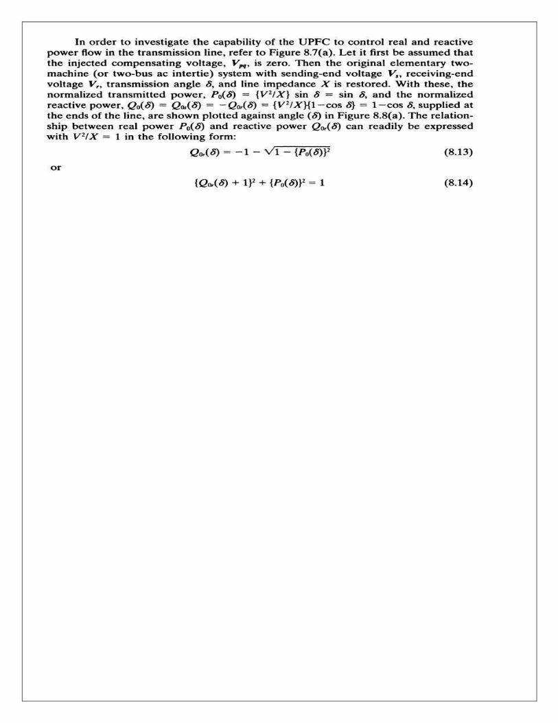


1

2
10. OHD/LCD SHEETS /CDS/DVDS/PPT (SOFT/HARD COPIES)

3
11. University Previous Question papers
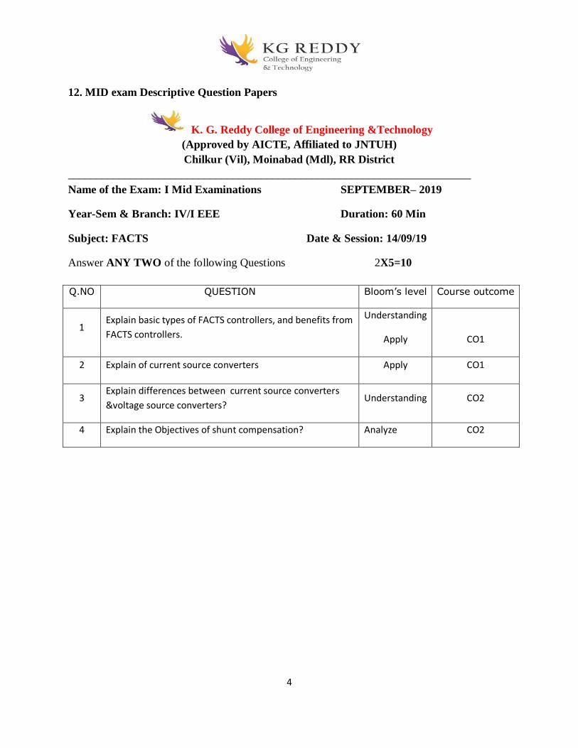
4
12. MID exam Descriptive Question Papers
K. G. Reddy College of Engineering &Technology
(Approved by AICTE, Affiliated to JNTUH)
Chilkur (Vil), Moinabad (Mdl), RR District
_______________________________________________________________________
Name of the Exam: I Mid Examinations SEPTEMBER– 2019
Year-Sem & Branch: IV/I EEE Duration: 60 Min
Subject: FACTS Date & Session: 14/09/19
Answer ANY TWO of the following Questions 2X5=10
Q.NO QUESTION Bloom’s level Course outcome
1 Explain basic types of FACTS controllers, and benefits from
FACTS controllers.
Understanding
Apply
CO1
2 Explain of current source converters Apply CO1
3 Explain differences between current source converters
&voltage source converters? Understanding CO2
4 Explain the Objectives of shunt compensation? Analyze CO2
5
14. Assignment topics with materials
Unit-I
1. What are the two basic approaches for controllable series compensation?
Thyristor controlled series capacitor ( TCSC ) is a thyristor based series
compensator that connects a thyristor controlled reactor ( TCR ) in parallel with a
fixed capacitor. By varying the firing angle of the anti-parallel thyristors that are
connected in series with a reactor in the TCR, the fundamental frequency inductive
reactance of the TCR can be changed. This effect a change in the reactance of the
TCSC and it can be controlled to produce either inductive or capacitive reactance.
Alternatively a static synchronous series compensator or SSSC can be used for series
compensation. An SSSC is an SVS based all GTO based device which contains a VSC. The
VSC is driven by a dc capacitor. The output of the VSC is connected to a three-phase
transformer. The other end of the transformer is connected in series with the transmission line.
Unlike the TCSC, which changes the impedance of the line, an SSSC injects a voltage in the
line in quadrature with the line current. By making the SSSC voltage to lead or lag the line
current by 90 °, the SSSC can emulate the behavior of an inductance or capacitance.
2. What is FACTS?
The term FACTS is an acronym for Flexible Alternating Current Transmission Systems In its
most general expression, the FACTS concept is based on the incorporation of power
electronic devices and methods into the high-voltage side of the network, to make it
electronically controllable. FACTS looks at ways of capitalizing on the many breakthroughs
taking place in the area of high-voltage and high-current power electronics, aiming at
increasing the control of power flows in the high-voltage side of the network during both
steady-state and transient conditions.
3. State the objectives of FACTS controller?
The main objectives of FACTS controllers are the following: 1.Regulation of power
flows in prescribed transmission routes. 2.Secure loading of transmission lines nearer
to their thermal limits.Prevention of cascading outages by contributing to emergency
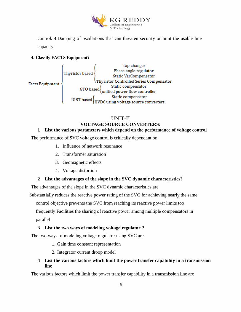
6
control. 4.Damping of oscillations that can threaten security or limit the usable line
capacity.
4. Classify FACTS Equipment?
UNIT-II VOLTAGE SOURCE CONVERTERS:
1. List the various parameters which depend on the performance of voltage control
The performance of SVC voltage control is critically dependant on
1. Influence of network resonance
2. Transformer saturation
3. Geomagnetic effects
4. Voltage distortion
2. List the advantages of the slope in the SVC dynamic characteristics?
The advantages of the slope in the SVC dynamic characteristics are
Substantially reduces the reactive power rating of the SVC for achieving nearly the same
control objective prevents the SVC from reaching its reactive power limits too
frequently Facilities the sharing of reactive power among multiple compensators in
parallel
3. List the two ways of modeling voltage regulator ?
The two ways of modeling voltage regulator using SVC are
1. Gain time constant representation
2. Integrator current droop model
4. List the various factors which limit the power transfer capability in a transmission
line
The various factors which limit the power transfer capability in a transmission line are
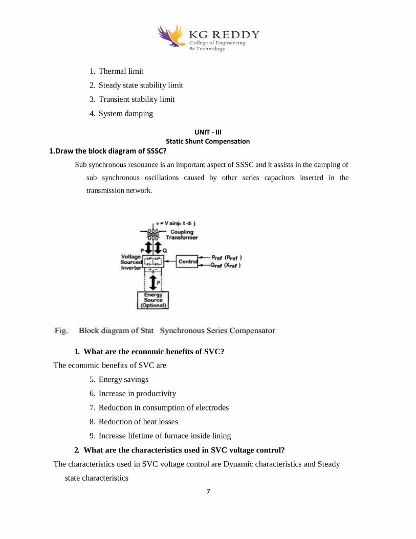
7
1. Thermal limit
2. Steady state stability limit
3. Transient stability limit
4. System damping
UNIT - III
Static Shunt Compensation
1.Draw the block diagram of SSSC?
Sub synchronous resonance is an important aspect of SSSC and it assists in the damping of
sub synchronous oscillations caused by other series capacitors inserted in the
transmission network.
1. What are the economic benefits of SVC?
The economic benefits of SVC are
5. Energy savings
6. Increase in productivity
7. Reduction in consumption of electrodes
8. Reduction of heat losses
9. Increase lifetime of furnace inside lining
2. What are the characteristics used in SVC voltage control?
The characteristics used in SVC voltage control are Dynamic characteristics and Steady
state characteristics
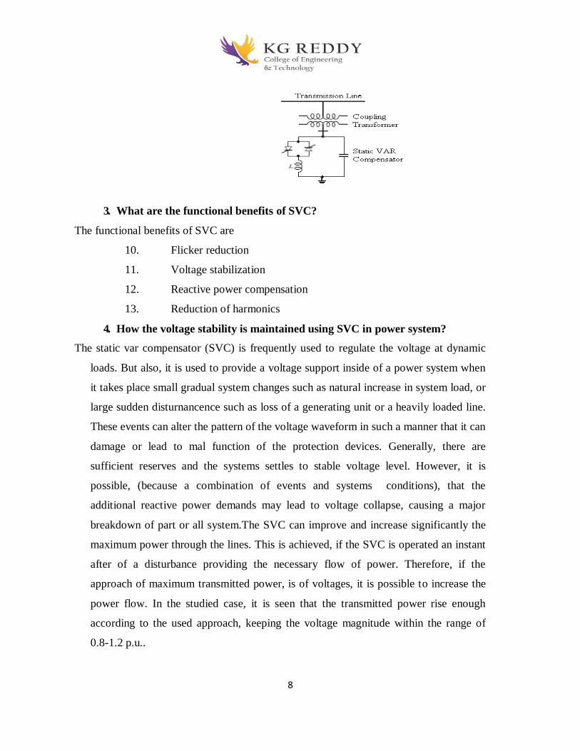
8
3. What are the functional benefits of SVC?
The functional benefits of SVC are
10. Flicker reduction
11. Voltage stabilization
12. Reactive power compensation
13. Reduction of harmonics
4. How the voltage stability is maintained using SVC in power system?
The static var compensator (SVC) is frequently used to regulate the voltage at dynamic
loads. But also, it is used to provide a voltage support inside of a power system when
it takes place small gradual system changes such as natural increase in system load, or
large sudden disturnancence such as loss of a generating unit or a heavily loaded line.
These events can alter the pattern of the voltage waveform in such a manner that it can
damage or lead to mal function of the protection devices. Generally, there are
sufficient reserves and the systems settles to stable voltage level. However, it is
possible, (because a combination of events and systems conditions), that the
additional reactive power demands may lead to voltage collapse, causing a major
breakdown of part or all system.The SVC can improve and increase significantly the
maximum power through the lines. This is achieved, if the SVC is operated an instant
after of a disturbance providing the necessary flow of power. Therefore, if the
approach of maximum transmitted power, is of voltages, it is possible to increase the
power flow. In the studied case, it is seen that the transmitted power rise enough
according to the used approach, keeping the voltage magnitude within the range of
0.8-1.2 p.u..
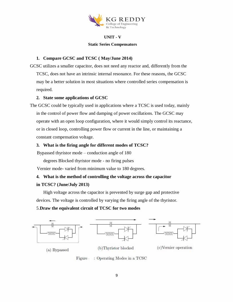
9
UNIT - V
Static Series Compensators
1. Compare GCSC and TCSC ( May/June 2014)
GCSC utilizes a smaller capacitor, does not need any reactor and, differently from the
TCSC, does not have an intrinsic internal resonance. For these reasons, the GCSC
may be a better solution in most situations where controlled series compensation is
required.
2. State some applications of GCSC
The GCSC could be typically used in applications where a TCSC is used today, mainly
in the control of power flow and damping of power oscillations. The GCSC may
operate with an open Ioop configuration, where it would simply control its reactance,
or in closed loop, controlling power flow or current in the line, or maintaining a
constant compensation voltage.
3. What is the firing angle for different modes of TCSC?
Bypassed thyristor mode – conduction angle of 180
degrees Blocked thyristor mode - no firing pulses
Vernier mode- varied from minimum value to 180 degrees.
4. What is the method of controlling the voltage across the capacitor
in TCSC? (June/July 2013)
High voltage across the capacitor is prevented by surge gap and protective
devices. The voltage is controlled by varying the firing angle of the thyristor.
5.Draw the equivalent circuit of TCSC for two modes

10
15. Tutorial topics and Questions No tutorial classes

11
16. Unit wise-Question bank
UNIT-I
FACTS
2-Marks Question and answers
1. Define Flexibility of Electric Power Transmission systems ?
Flexibility of Electric Power Transmission. The ability to accommodate changes in the
electric transmission system or operating conditions while maintaining sufficient steady
Flexible AC Transmission System (FACTS). Alternating current transmission systems
incorporating power electronic-based and other static controllers to enhance controllability and
increase power transfer capability.
FACTS Controller. A power electronic-based system and other static equipment that provide
control of one or more AC transmission system parameters.
2. Explain TCSR? Thyristor-Controlled Series Reactor (TCSR): An inductive reactance compensator which
consists of a series reactor shunted by a thyristor controlled reactor in order to provide a
smoothly variable series inductive reactance.When the firing angle of the thyristor controlled
reactor is 180 degrees, it stops conducting, and the uncontrolled reactor acts as a fault current
limiter [Figure 1.6(d)]. As the angle decreases below 180 degrees, the net inductance
decreases until firing angle of 90 degrees, when the net inductance is the parallel
combination of the two reactors. As for the TCSC, the TCSR may be a single large unit or
several smaller series units
3. What is UPFC?
Unified Power Flow Controller (UPFC): A combination of static synchronous compensator
(STATCOM) and a static series compensator (SSSC) which are coupled via a common dc link,
to allow bidirectional flow of real power between the series output terminals of the SSSC and the
shunt output terminals of the STATCOM, and are controlled to provide concurrent real and
reactive series line compensation without an external electric energy source. The UPFC, by
means of angularly unconstrained series voltage injection, is able to control, concurrently or
selectively, the transmission line voltage, impedance, and angle or, alternatively, the real and
reactive power flow in the line. The UPFC may also provide independently controllable shunt
reactive compensation.
12
4. write types of FACTS controllers?
The potential difference across any two ends of a conductor is directly Proportional to the current
flowing between the two ends provided the Temperature of the conductor remains constant.
5. What are the benefits of FACTS?
Increase the system security through raising the transient stability limits, limiting short-
circuit currents and overloads, managing cascading blackouts and damping electro- mechanical
oscillations of power systems and machines.
• Provide secure tie line connections to neighboring utilities and regions thereby
decreasing overall generation reserve requirements on both sides.
• Provide greater flexibility in sitting new generation.
• Upgrade of lines.
• Reduce reactive power flows, thus allowing the lines to carry more active power.
• Reduce loop flows.
• Increase utilization of lowest cost generation. One of the principal reasons for
transmission interconnections is to utilize lowest cost generation. When this cannot be done, it
follows that there is not enough cost-effective transmission capacity. Cost-effective enhancement
of capacity will therefore allow increased use of lowest cost generation.
3-Marks Question and answers
6 WHAT LIMITS THE LOADING CAPABILITY?
Basically, there are three kinds of limitations:
• Thermal
• Dielectric
• Stability
Thermal Thermal capability of an overhead line is a function of the ambient temperature, wind
conditions, condition of the conductor, and ground clearance. It varies perhaps by a factor of 2 to
1 due to the variable environment and the loading history.
Dielectric From an insulation point of view, many lines are designed very conservatively. For a
given nominal voltage rating, it is often possible to increase normal operation by +10% voltage
(i.e., 500 kV-550 kV) or even higher. Care is then needed to ensure that dynamic and transient
over voltages are within limits. Modern gapless arresters, or line insulators with internal gapless
arresters, or powerful thyristor-controlled overvoltage suppressors at the substations can enable
significant increase in the line and substation voltage capability.

13
Stability There are a number of stability issues that limit the transmission capability. These
include:
• Transient stability
• Dynamic stability
• Steady-state stability
• Frequency collapse
• Voltage collapse
• Sub synchronous resonance
7. Why is a flexible AC Transmission System Needed?
In conventional AC transmission system, the ability to transfer AC power is
limited by several factors like thermal limits, transient stability limit, voltage
limit, short circuit current limit etc.
These limits define the maximum electric power which can be efficiently
transmitted through the transmission line without causing any damage to the
electrical equipments and the transmission lines.
This is normally achieved by bringing changes in the power system layout.
However this is not feasible and another way of achieving maximum power
transfer capability without any changes in the power system layout.
Also with the introduction of variable impedance devices like capacitors and
inductors, whole of the energy or power from the source is not transferred to the
load, but a part is stored in these devices as reactive power and returned back to
the source.
Thus the actual amount of power transferred to the load or the active power is
always less than the apparent power or the net power.
For ideal transmission the active power should be equal to the apparent power. In
other words, the power factor (the ratio of active power to apparent power) should
be unity. This is where the role of Flexible AC transmission System comes.
8. Explain TCSC?
Thyristor Controlled Series Capacitor (TCSC): A capacitive reactance compensator which
consists of a series capacitor bank shunted by a thyristor-controlled reactor in order to provide a
smoothly variable series capacitive reactance.
The TCSC [Figure 1.6(c)], is based on thyristors without the gate turn-off capability. It is
an alternative to SSSC above and like an SSSC; it is a very important FACTS Controller. A
variable reactor such as a Thyristor-Controlled Reactor (TCR) is connected across a series
capacitor. When the TCR firing angle is 180 degrees, the reactor becomes non conducting and
the series capacitor has its normal impedance. As the firing angle is advanced from 180 degrees
to less than 180 degrees, the capacitive impedance increases. At the other end, when the TCR
firing angle is 90 degrees, the reactor becomes fully conducting, and the total impedance
becomes inductive, because the reactor impedance is designed to be much lower than the series
capacitor impedance. With 90 degrees firing angle, the
TCSC helps in limiting fault current. The TCSC may be a single, large unit, or may consist of
several equal or different-sized smaller capacitors in order to achieve a superior performance.
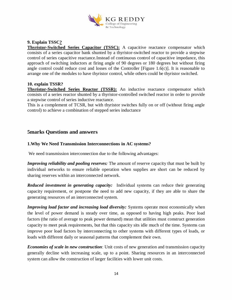
14
9. Explain TSSC?
Thyristor-Switched Series Capacitor (TSSC): A capacitive reactance compensator which
consists of a series capacitor bank shunted by a thyristor-switched reactor to provide a stepwise
control of series capacitive reactance.Instead of continuous control of capacitive impedance, this
approach of switching inductors at firing angle of 90 degrees or 180 degrees but without firing
angle control could reduce cost and losses of the Controller [Figure 1.6(c)]. It is reasonable to
arrange one of the modules to have thyristor control, while others could be thyristor switched.
10. explain TSSR?
Thyristor-Switched Series Reactor (TSSR): An inductive reactance compensator which
consists of a series reactor shunted by a thyristor-controlled switched reactor in order to provide
a stepwise control of series inductive reactance.
This is a complement of TCSR, but with thyristor switches fully on or off (without firing angle
control) to achieve a combination of stepped series inductance
5marks Questions and answers
1.Why We Need Transmission Interconnections in AC systems?
We need transmission interconnection due to the following advantages:
Improving reliability and pooling reserves: The amount of reserve capacity that must be built by
individual networks to ensure reliable operation when supplies are short can be reduced by
sharing reserves within an interconnected network.
Reduced investment in generating capacity: Individual systems can reduce their generating
capacity requirement, or postpone the need to add new capacity, if they are able to share the
generating resources of an interconnected system.
Improving load factor and increasing load diversity: Systems operate most economically when
the level of power demand is steady over time, as opposed to having high peaks. Poor load
factors (the ratio of average to peak power demand) mean that utilities must construct generation
capacity to meet peak requirements, but that this capacity sits idle much of the time. Systems can
improve poor load factors by interconnecting to other systems with different types of loads, or
loads with different daily or seasonal patterns that complement their own.
Economies of scale in new construction: Unit costs of new generation and transmission capacity
generally decline with increasing scale, up to a point. Sharing resources in an interconnected
system can allow the construction of larger facilities with lower unit costs.
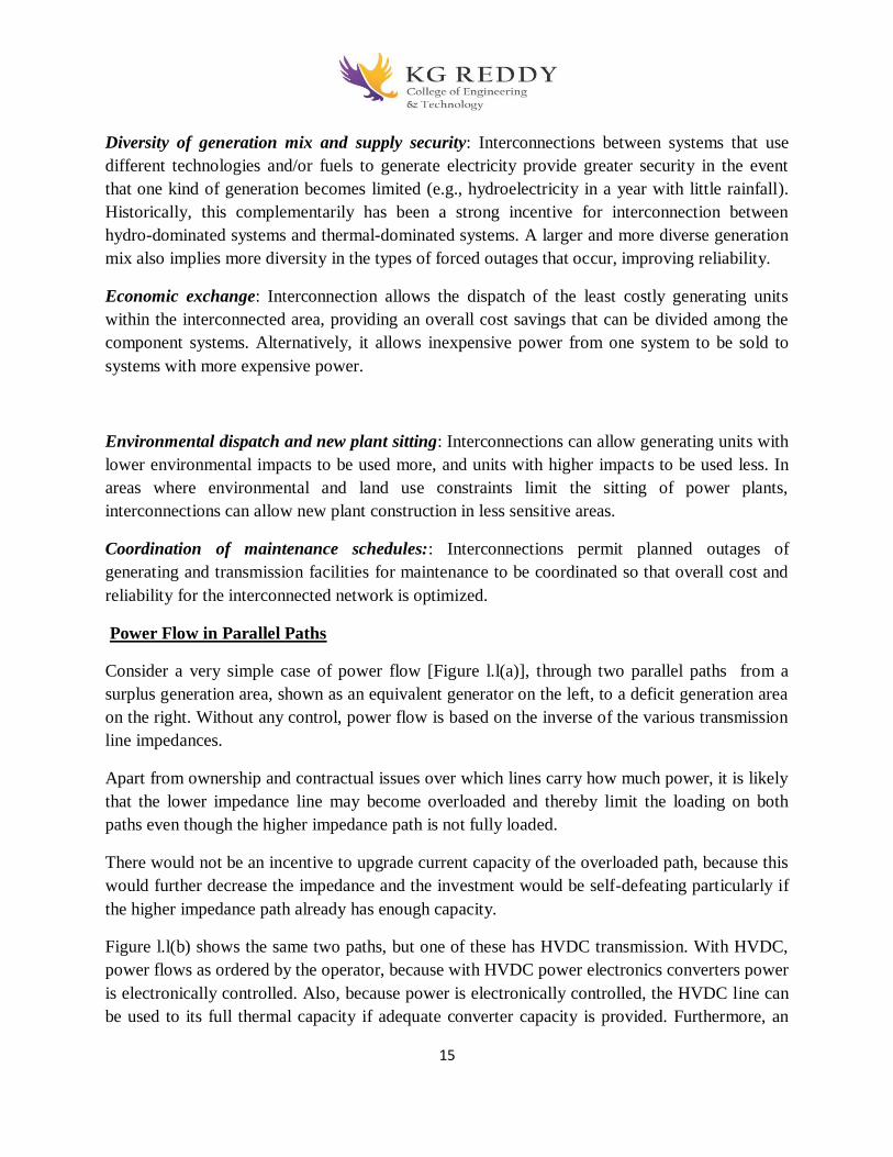
15
Diversity of generation mix and supply security: Interconnections between systems that use
different technologies and/or fuels to generate electricity provide greater security in the event
that one kind of generation becomes limited (e.g., hydroelectricity in a year with little rainfall).
Historically, this complementarily has been a strong incentive for interconnection between
hydro-dominated systems and thermal-dominated systems. A larger and more diverse generation
mix also implies more diversity in the types of forced outages that occur, improving reliability.
Economic exchange: Interconnection allows the dispatch of the least costly generating units
within the interconnected area, providing an overall cost savings that can be divided among the
component systems. Alternatively, it allows inexpensive power from one system to be sold to
systems with more expensive power.
Environmental dispatch and new plant sitting: Interconnections can allow generating units with
lower environmental impacts to be used more, and units with higher impacts to be used less. In
areas where environmental and land use constraints limit the sitting of power plants,
interconnections can allow new plant construction in less sensitive areas.
Coordination of maintenance schedules:: Interconnections permit planned outages of
generating and transmission facilities for maintenance to be coordinated so that overall cost and
reliability for the interconnected network is optimized.
Power Flow in Parallel Paths
Consider a very simple case of power flow [Figure l.l(a)], through two parallel paths from a
surplus generation area, shown as an equivalent generator on the left, to a deficit generation area
on the right. Without any control, power flow is based on the inverse of the various transmission
line impedances.
Apart from ownership and contractual issues over which lines carry how much power, it is likely
that the lower impedance line may become overloaded and thereby limit the loading on both
paths even though the higher impedance path is not fully loaded.
There would not be an incentive to upgrade current capacity of the overloaded path, because this
would further decrease the impedance and the investment would be self-defeating particularly if
the higher impedance path already has enough capacity.
Figure l.l(b) shows the same two paths, but one of these has HVDC transmission. With HVDC,
power flows as ordered by the operator, because with HVDC power electronics converters power
is electronically controlled. Also, because power is electronically controlled, the HVDC line can
be used to its full thermal capacity if adequate converter capacity is provided. Furthermore, an

16
HVDC line, because of its high-speed control, can also help the parallel ac transmission line to
maintain stability.
However, HVDC is expensive for general use, and is usually considered when long distances are
involved, such as the Pacific DC Intertie on which power flows as ordered by the operator.
As alternative FACTS Controllers, Figures l.l(c) and 1.1 (d) show one of the transmission lines
with different types of series type FACTS Controllers. By means of controlling impedance
[Figure l.l(c)] or phase angle [Figure l.l(d)], or series injection of appropriate voltage (not shown)
a FACTS Controller can control the power flow as required. Maximum power flow can in fact be
limited to its rated limit under contingency conditions when this line is expected to carry more
power due to the loss of a parallel line.
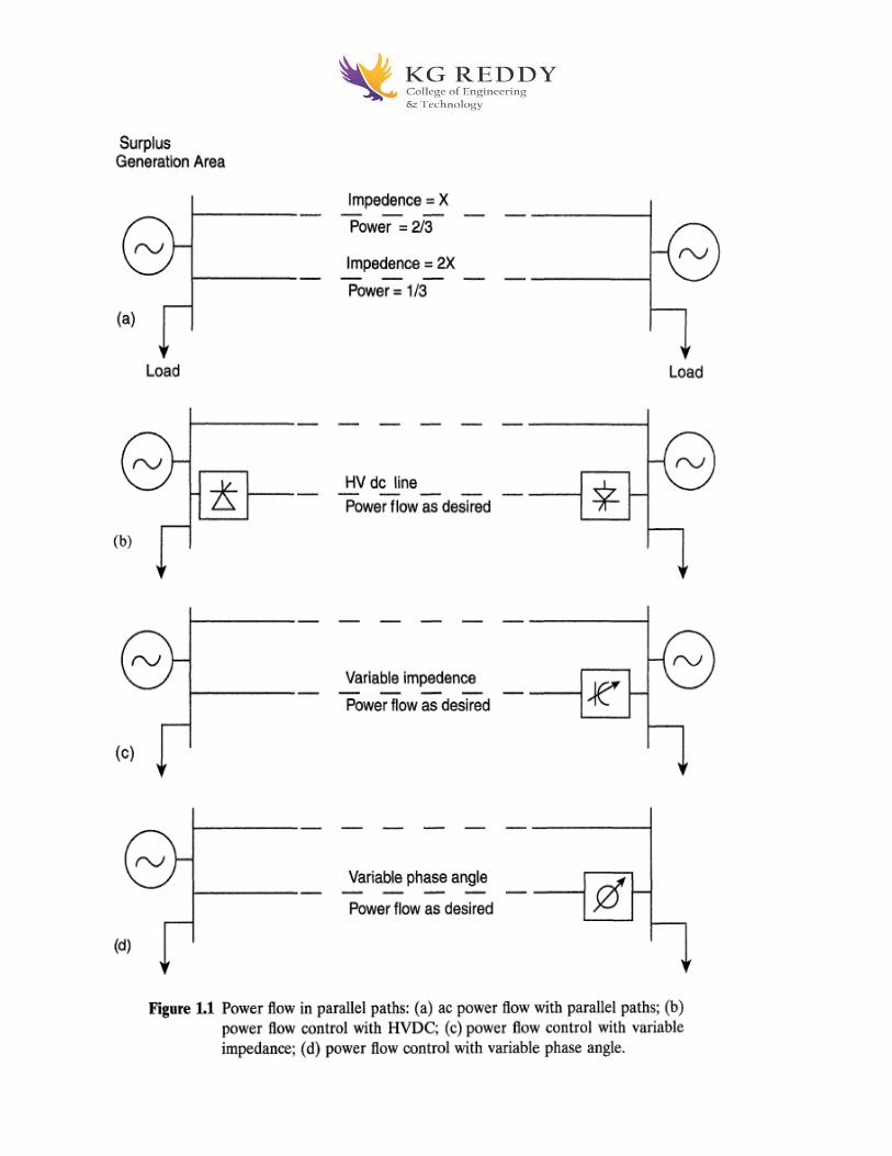
17
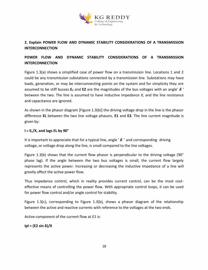
18
2. Explain POWER FLOW AND DYNAMIC STABILITY CONSIDERATIONS OF A TRANSMISSION
INTERCONNECTION
POWER FLOW AND DYNAMIC STABILITY CONSIDERATIONS OF A TRANSMISSION
INTERCONNECTION
Figure 1.3(a) shows a simplified case of power flow on a transmission line. Locations 1 and 2
could be any transmission substations connected by a transmission line. Substations may have
loads, generation, or may be interconnecting points on the system and for simplicity they are
assumed to be stiff busses.E1 and E2 are the magnitudes of the bus voltages with an angle’ δ ‘
between the two. The line is assumed to have inductive impedance X, and the line resistance
and capacitance are ignored.
As shown in the phasor diagram [Figure 1.3(b)] the driving voltage drop in the line is the phasor
difference EL between the two line voltage phasors, E1 and E2. The line current magnitude is
given by:
I = EL/X, and lags EL by 90°
It is important to appreciate that for a typical line, angle ’ δ ‘ and corresponding driving
voltage, or voltage drop along the line, is small compared to the line voltages.
Figure 1.3(b) shows that the current flow phasor is perpendicular to the driving voltage (90°
phase lag). If the angle between the two bus voltages is small, the current flow largely
represents the active power. Increasing or decreasing the inductive impedance of a line will
greatly affect the active power flow.
Thus impedance control, which in reality provides current control, can be the most cost-
effective means of controlling the power flow. With appropriate control loops, it can be used
for power flow control and/or angle control for stability.
Figure 1.3(c), corresponding to Figure 1.3(b), shows a phasor diagram of the relationship
between the active and reactive currents with reference to the voltages at the two ends.
Active component of the current flow at E1 is:
Ipl = (E2 sin δ)/X
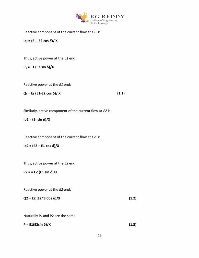
19
Reactive component of the current flow at E1 is:
Iql = (E1 - E2 cos δ)/ X
Thus, active power at the E1 end:
P1 = E1 (E2 sin δ)/X
Reactive power at the E1 end:
Q1 = E1 E1-E2 cos δ)/ X (1.1)
Similarly, active component of the current flow at E2 is:
Ip2 = (E1 sin δ)/X
Reactive component of the current flow at E2 is:
Iq2 = (E2 – E1 cos δ)/X
Thus, active power at the E2 end:
P2 = = E2 (E1 sin δ)/X
Reactive power at the E2 end:
Q2 = E2 (E2~ElCos δ)/X (1.2)
Naturally P1 and P2 are the same:
P = E1(E2sin δ)/X (1.3)
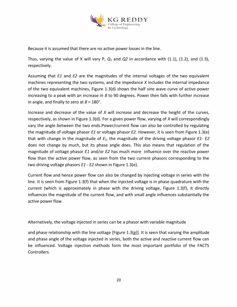
20
Because it is assumed that there are no active power losses in the line.
Thus, varying the value of X will vary P, Q1 and Q2 in accordance with (1.1), (1.2), and (1.3),
respectively.
Assuming that E1 and E2 are the magnitudes of the internal voltages of the two equivalent
machines representing the two systems, and the impedance X includes the internal impedance
of the two equivalent machines, Figure 1.3(d) shows the half sine wave curve of active power
increasing to a peak with an increase in 8 to 90 degrees. Power then falls with further increase
in angle, and finally to zero at 8 = 180°.
Increase and decrease of the value of X will increase and decrease the height of the curves,
respectively, as shown in Figure 1.3(d). For a given power flow, varying of X will correspondingly
vary the angle between the two ends.Power/current flow can also be controlled by regulating
the magnitude of voltage phasor E1 or voltage phasor E2. However, it is seen from Figure 1.3(e)
that with change in the magnitude of E1, the magnitude of the driving voltage phasor E1- E2
does not change by much, but its phase angle does. This also means that regulation of the
magnitude of voltage phasor E1 and/or E2 has much more influence over the reactive power
flow than the active power flow, as seen from the two current phasors corresponding to the
two driving voltage phasors E1 - E2 shown in Figure 1.3(e).
Current flow and hence power flow can also be changed by injecting voltage in series with the
line. It is seen from Figure 1.3(f) that when the injected voltage is in phase quadrature with the
current (which is approximately in phase with the driving voltage, Figure 1.3(f), it directly
influences the magnitude of the current flow, and with small angle influences substantially the
active power flow.
Alternatively, the voltage injected in series can be a phasor with variable magnitude
and phase relationship with the line voltage [Figure 1.3(g)]. It is seen that varying the amplitude
and phase angle of the voltage injected in series, both the active and reactive current flow can
be influenced. Voltage injection methods form the most important portfolio of the FACTS
Controllers.

21

22
3. Explain Shunt Connected Controllers?
Static Synchronous Compensator (STATCOM): A Static synchronous generator operated as a
shunt-connected static var compensator whose capacitive or inductive output current can be
controlled independent of the ac system voltage.
STATCOM is one of the key FACTS Controllers. It can be based on a voltage sourced or
current-sourced converter. Figure 1.5(a) shows a simple one-line diagram of STATCOM based
on a voltage-sourced converter and a current-sourced converter.
For the voltage-sourced converter, its ac output voltage is controlled such that it is just right for
the required reactive current flow for any ac bus voltage dc capacitor voltage is automatically
adjusted as required to serve as a voltage source for the converter. STATCOM can be designed
to also act as an active filter to absorb system harmonics.
Battery Energy Storage System (BESS): A chemical-based energy storage system using shunt
connected voltage-source converters capable of rapidly adjusting the amount of energy which is
supplied to or absorbed from an ac system.
Figure 1.5(b) shows a simple one-line diagram in which storage means is connected to a
STATCOM. For transmission applications, BESS storage unit sizes would tend to be small (a
few tens of MWHs), and if the short-time converter rating was large enough, it could deliver
MWs with a high MW/MWH ratio for transient stability.
The converter can also simultaneously absorb or deliver reactive power within the converter's
MVA capacity. When not supplying active power to the system, the converter is used to charge
the battery at an acceptable rate.
Static Var Compensator (SVC): A shunt-connected static var generator or absorber whose
output is adjusted to exchange capacitive or inductive current so as to maintain or control
specific parameters of the electrical power system (typically bus voltage).
This is a general term for a thyristor-controlled or thyristor-switched reactor, and/or
thyristor-switched capacitor or combination [Figure 1.5(c)]. SVC is based on thyristors without
the gate turn-off capability. It includes separate equipment for leading and lagging vars; the
thyristor-controlled or thyristor-switched reactor for absorbing reactive power and thyristor-
switched capacitor for supplying the reactive power. SVC is considered by some as a lower cost
alternative to STATCOM, although this may not be the case if the comparison is made based on
the required performance and not just the MVA size.
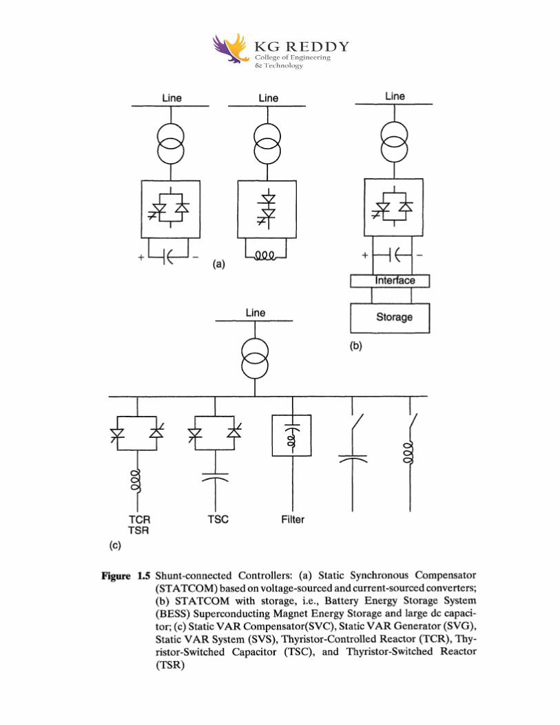
23

24
4. Explain Series Connected Controllers?
Static Synchronous Series Compensator (SSSC): A static synchronous generator operated
without an external electric energy source as a series compensator whose output voltage is in
quadrature with, and controllable independently of, the line current for the purpose of increasing
or decreasing the overall reactive voltage drop across the line and thereby controlling the
transmitted electric power. The SSSC may include transiently rated energy storage or energy
absorbing devices to enhance the dynamic behavior of the power system by additional temporary
real power compensation, to increase or decrease momentarily, the overall real (resistive) voltage
drop across the line.

25
SSSC is one the most important FACTS Controllers. It is like a STATCOM, except that
the output ac voltage is in series with the line. It can be based on a voltage sourced converter
[Figure 1.6(a)] or current-sourced converter. Usually the injected voltage in series would be quite
small compared to the line voltage, and the insulation to ground would be quite high.
SSSC can only inject a variable voltage, which is 90 degrees leading or lagging the
current. The primary of the transformer and hence the secondary as well as the converter has to
carry full line current including the fault current unless the converter is temporarily bypassed
during severe line faults.
Battery-storage or superconducting magnetic storage can also be connected to a series Controller
[Figure 1.6(b)] to inject a voltage vector of variable angle in series with the line.
5. Explain Combined Shunt and Series Connected Controllers with befits of facts?
Combined Shunt and Series Connected Controllers Unified Power Flow Controller (UPFC): A combination of static synchronous compensator
(STATCOM) and a static series compensator (SSSC) which are coupled via a common dc link,
to allow bidirectional flow of real power between the series output terminals of the SSSC and the
shunt output terminals of the STATCOM, and are controlled to provide concurrent real and
reactive series line compensation without an external electric energy source. The UPFC, by
means of angularly unconstrained series voltage injection, is able to control, concurrently or
selectively, the transmission line voltage, impedance, and angle or, alternatively, the real and
reactive power flow in the line. The UPFC may also provide independently controllable shunt
reactive compensation.
In UPFC [Figure 1.7], which combines a STATCOM [Figure 1.5(a)] and an SSSC
[Figure 1.6(a)], the active power for the series unit (SSSC) is obtained from the line itself via the
shunt unit STATCOM; the latter is also used for voltage control with control of its reactive
power. This is a complete Controller for controlling active and reactive power control through
the line, as well as line voltage control.
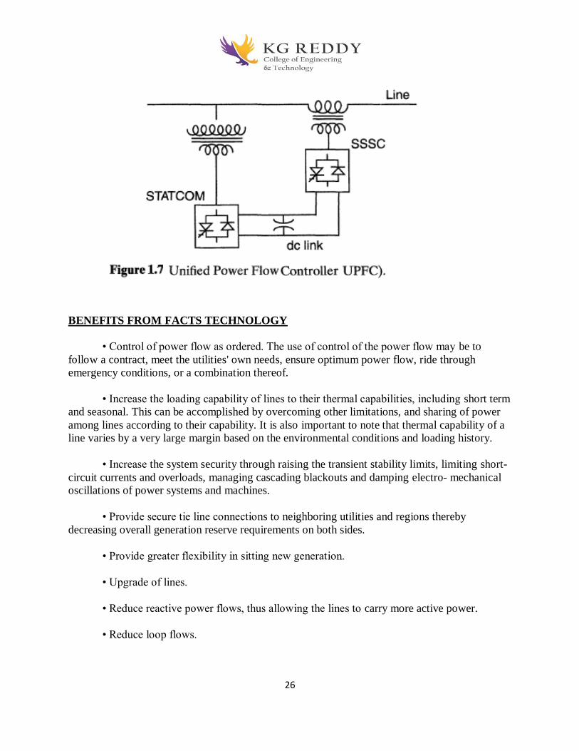
26
BENEFITS FROM FACTS TECHNOLOGY
• Control of power flow as ordered. The use of control of the power flow may be to
follow a contract, meet the utilities' own needs, ensure optimum power flow, ride through
emergency conditions, or a combination thereof.
• Increase the loading capability of lines to their thermal capabilities, including short term
and seasonal. This can be accomplished by overcoming other limitations, and sharing of power
among lines according to their capability. It is also important to note that thermal capability of a
line varies by a very large margin based on the environmental conditions and loading history.
• Increase the system security through raising the transient stability limits, limiting short-
circuit currents and overloads, managing cascading blackouts and damping electro- mechanical
oscillations of power systems and machines.
• Provide secure tie line connections to neighboring utilities and regions thereby
decreasing overall generation reserve requirements on both sides.
• Provide greater flexibility in sitting new generation.
• Upgrade of lines.
• Reduce reactive power flows, thus allowing the lines to carry more active power.
• Reduce loop flows.

27
• Increase utilization of lowest cost generation. One of the principal reasons for
transmission interconnections is to utilize lowest cost generation. When this cannot be done, it
follows that there is not enough cost-effective transmission capacity. Cost-effective enhancement
of capacity will therefore allow increased use of lowest cost generation.
Objective Type Questions
1. Potential difference in electrical terminology is known as?
a) Voltage
b) Current
c) Resistance
d) Conductance
2. The circuit in which current has a complete path to flow is called ______ circuit.
a) short
b) open
c) closed
d) open loop
3. If the voltage-current characteristics are a straight line through the origin, then the
element is said to be?
a) Linear element
b) Non-linear element
c) Unilateral element
d) Bilateral element
4. The voltage across R1 resistor in the circuit shown below is?
a) 10
b) 5
c) 2.5
d) 1.25
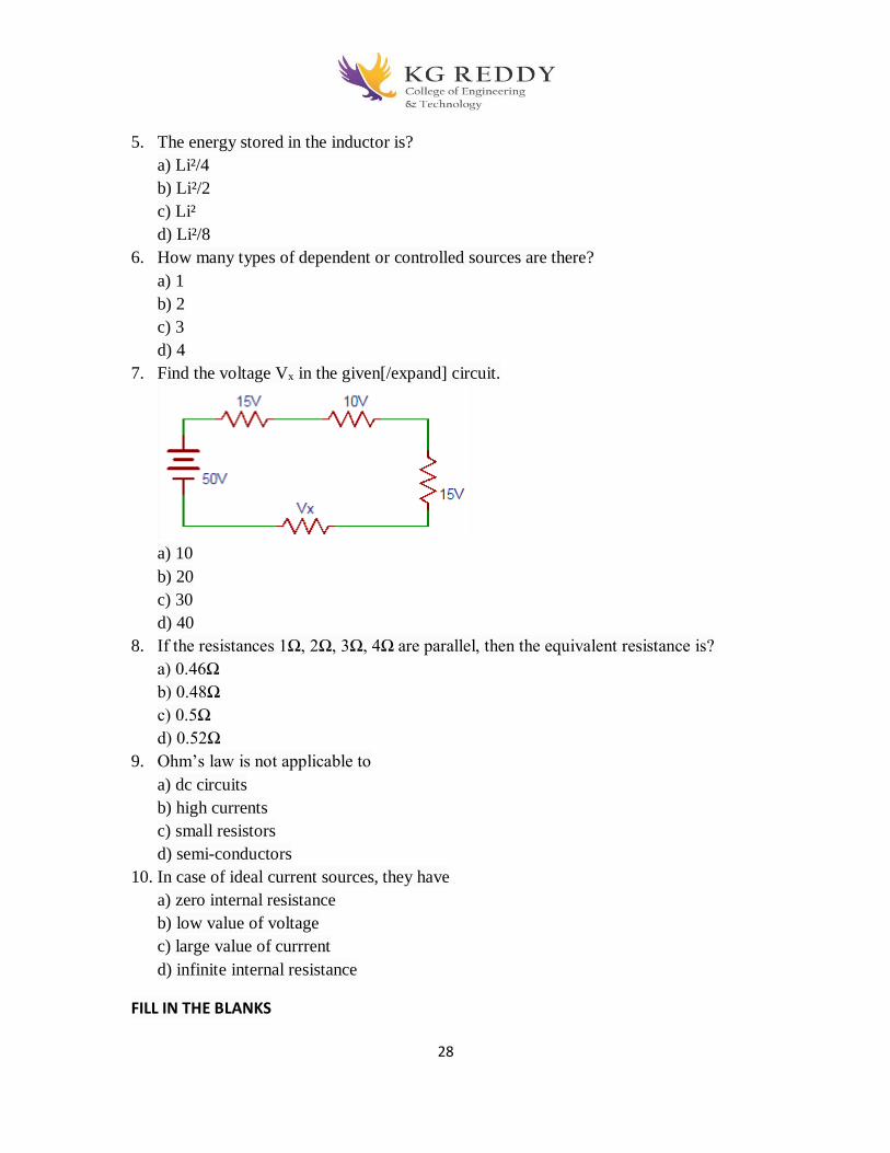
28
5. The energy stored in the inductor is?
a) Li²/4
b) Li²/2
c) Li²
d) Li²/8
6. How many types of dependent or controlled sources are there?
a) 1
b) 2
c) 3
d) 4
7. Find the voltage Vx in the given[/expand] circuit.
a) 10
b) 20
c) 30
d) 40
8. If the resistances 1Ω, 2Ω, 3Ω, 4Ω are parallel, then the equivalent resistance is?
a) 0.46Ω
b) 0.48Ω
c) 0.5Ω
d) 0.52Ω
9. Ohm’s law is not applicable to
a) dc circuits
b) high currents
c) small resistors
d) semi-conductors
10. In case of ideal current sources, they have
a) zero internal resistance
b) low value of voltage
c) large value of currrent
d) infinite internal resistance
FILL IN THE BLANKS
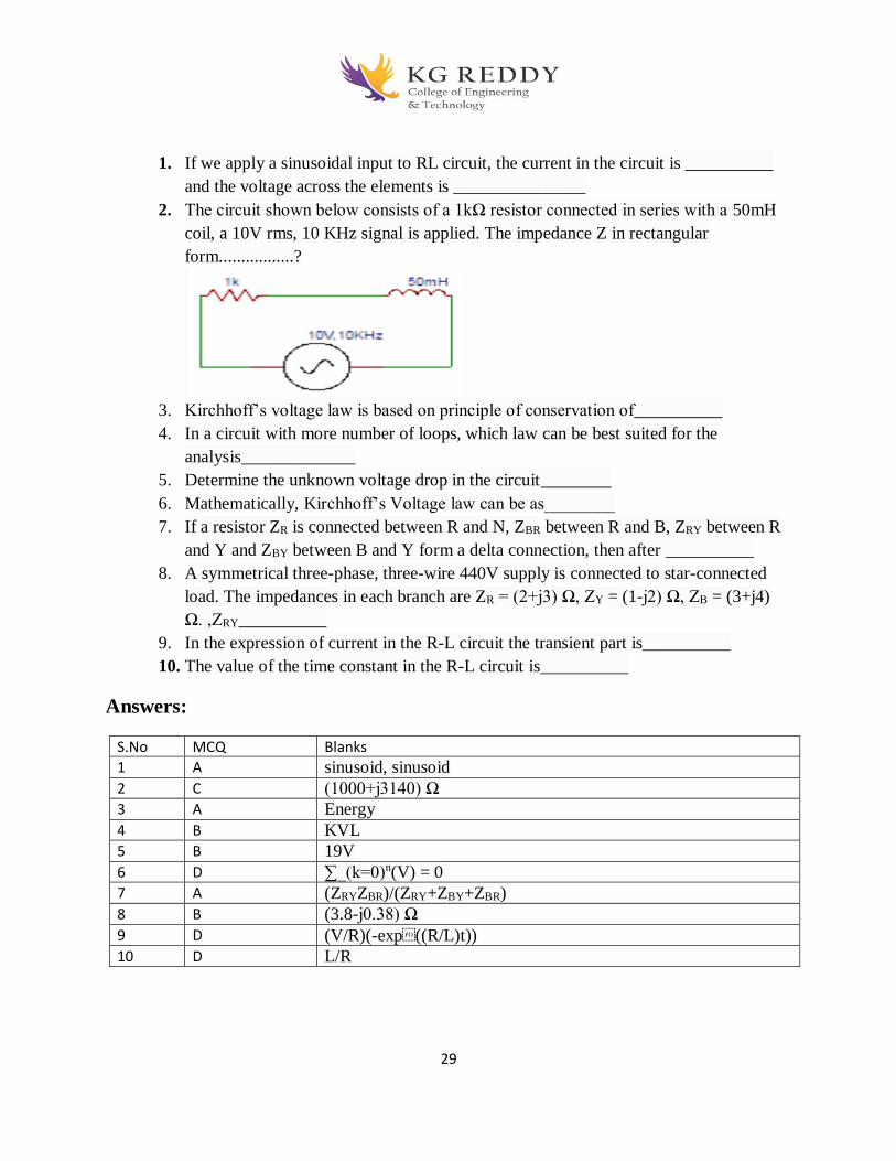
29
1. If we apply a sinusoidal input to RL circuit, the current in the circuit is __________
and the voltage across the elements is _______________
2. The circuit shown below consists of a 1kΩ resistor connected in series with a 50mH
coil, a 10V rms, 10 KHz signal is applied. The impedance Z in rectangular
form.................?
3. Kirchhoff’s voltage law is based on principle of conservation of__________
4. In a circuit with more number of loops, which law can be best suited for the
analysis_____________
5. Determine the unknown voltage drop in the circuit________
6. Mathematically, Kirchhoff’s Voltage law can be as________
7. If a resistor ZR is connected between R and N, ZBR between R and B, ZRY between R
and Y and ZBY between B and Y form a delta connection, then after __________
8. A symmetrical three-phase, three-wire 440V supply is connected to star-connected
load. The impedances in each branch are ZR = (2+j3) Ω, ZY = (1-j2) Ω, ZB = (3+j4)
Ω. ,ZRY__________
9. In the expression of current in the R-L circuit the transient part is__________
10. The value of the time constant in the R-L circuit is__________
Answers:
S.No MCQ Blanks
1 A sinusoid, sinusoid
2 C (1000+j3140) Ω
3 A Energy
4 B KVL
5 B 19V
6 D ∑_(k=0)n(V) = 0
7 A (ZRYZBR)/(ZRY+ZBY+ZBR)
8 B (3.8-j0.38) Ω
9 D (V/R)(-exp((R/L)t))
10 D L/R
30
UNIT-II
Current source converters
2-Marks Question and answers
1.What is the necessity of compensation?
The reactive power through the system can significantly improve the performance parameters of
the power system as follows Voltage profile Power angle characteristics Stability margin
Damping to power oscillations
2. What are the objectives of line compensation?
To increase the power transmission capacity of the line To keep the voltage profile of the line
along its length within acceptable bounds to ensure the quality of supply to the connected
customer as well as to minimize the line insulation costs
3. How is the reactive power controlled, using FACTS devices?
The SVC is a shunt device of the FACTS group, regulates voltage at its terminals by controlling
the amount of reactive power injected in to or absorbed from the power system. When a system
voltage is low, the SVC generates reactive power (SVC Capacitive). When a system voltage is
high, it absorbs reactive power (SVC inductive)
4. How is reactive power controlled in electrical network?
Traditionally, rotating synchronous condensers and fixed or mechanically switched capacitors or
inductors have been used for reactive power compensation. However, in recent years static VAR
compensators are used to provide or absorb the required reactive power have been developed.
5. Explain the objectives of FACTS controllers in the power system network?
Better the control of power flow (Real and Reactive) in transmission lines. Limits SC current Increase the load ability of the system increase dynamic and transient stability of power system Load compensation Power quality improvement

31
3-Marks Question and answers
1. Distinguish between a mesh and a loop of a circuit.
A mesh is a loop that does not contain other loops. All meshes are loop, but all loops are not
meshes. A loop is any closed path of branches
2. Write down the formula for a star connected network is converted into a
delta network?
RA=( R1 R2)/( R1 +R2+ R3)
RB=( R1 R3)/( R1 +R2+ R3)
RC=( R2 R3)/( R1 +R2+ R3)
3. Write down the formula for a delta connected network is converted into a
star network?
R1=( RARB+RBRC+RCRA)/RC
R2=( RARB+RBRC+RCRA)/RB
R3=( RARB+RBRC+RCRA)/RA
4. Define line currents and phase currents?
The currents flowing in the lines are called as line currents. The currents flowing through phase
are called phase currents
5. Define line voltage and phase voltage?
The voltage across one phase and neutral is called line voltage & the voltage between two lines
is called phase voltage

32
5 marks Questions and answers
1. what is a voltage source converter?
VOLTAGE SOURCE CONVERTERS
Fig 2.1 Single Phase Full Wave Bridge Converter
Operation of Single Phase Bridge Converter
Fig 2.1 shows a single phase bridge converter consisting of four valves i.e. valves (1-1')
to (4 -4'), a capacitor to provide stiff D.C. Voltage and two A.C. connection points „a‟ and „b‟.
The designated valve numbers represent their sequence of turn on and turn off operation. The
D.C. voltage is converted to A.C. voltage with the appropriate valve turn-on sequence, as
explained below. As in the first wave form 2.2 (a) when devices 1and 2 are turned on voltage
„Vab‟ becomes „+Vd‟ for one half cycle and when devices 3 and 4 turned on “Vab” becomes
“-Vd” for the other half cycle. Suppose the current flow in Fig 2.2 (b) is A.C. wave form which
is a sinusoidal wave form “Iab” the angle “θ” leads with respect to the square-wave voltage wave
form t1 the operation is illustrated.

33
Fig 2.2 Single phase full wave bridge converter
1. From instant t1 to t2 when devices 1 and 2 are ON and 3 and 4 are OFF, “Vab” is +ve and Iab
is -ve. The current flows through device 1 into A.C. phase “a” and then out of A.C. phase “b”
through device “2” with power flow from D.C. to A.C. (inverter action).
2. From instant t2 to t3 the current reverses i.e. becomes +ve and flows through diodes 1' and 2'
with power flow from A.C. to D.C. (rectifier action).
3. From instant t3 and t4 device 1 and 2 are OFF and 3 and 4 are ON, Vab becomes -ve and Iab
is still +ve the current flow through devices 3 and 4 with power flow from D.C. to A.C. (inverter
action).
4. From instant t4 and t5 devices 3 and 4 still ON and 1 and 2 OFF Vab is -ve current Iab
reverses and flows through diodes 3' and 4' with power flow from A.C. to D.C. (rectifier
operation). Fig 2.3(c) shows D.C. current wave form and Fig 2.3(d) shows Voltage across valve
(1-1') Fig 2.3(e) shows phasor of power flow from A.C. to D.C. with lagging power factor. Four
operating modes in one cycle of a single phase converter are shown in table
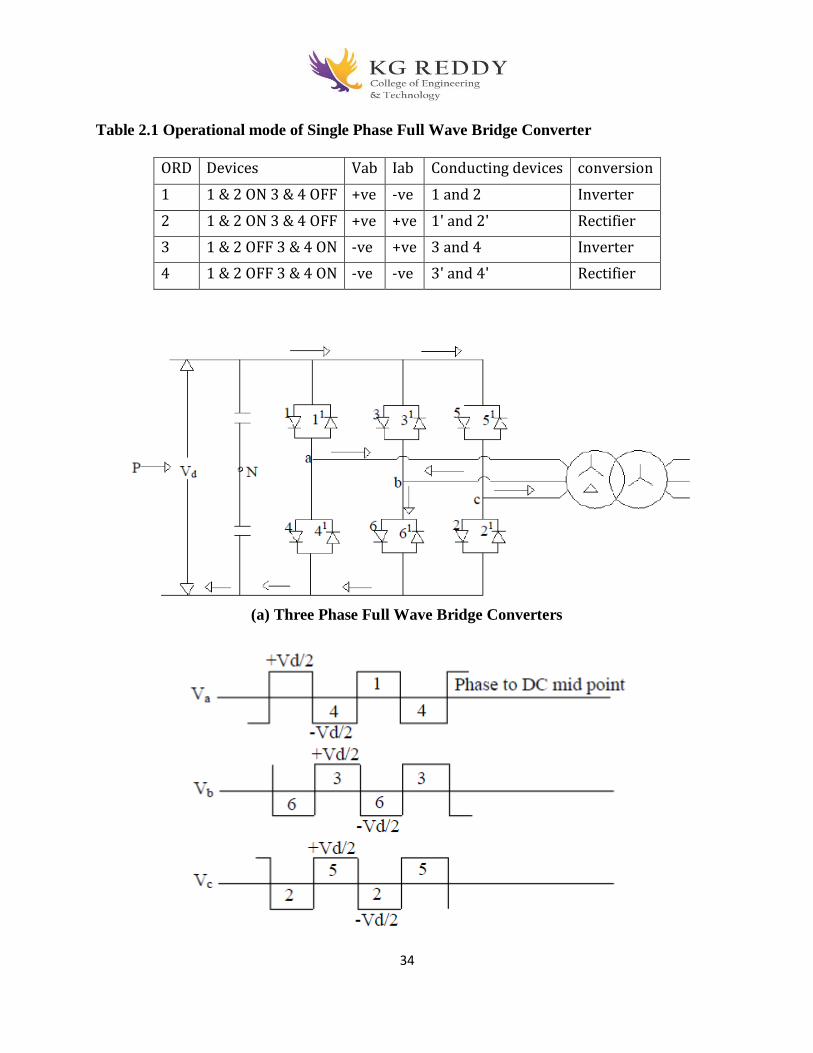
34
Table 2.1 Operational mode of Single Phase Full Wave Bridge Converter
ORD Devices Vab Iab Conducting devices conversion
1 1 & 2 ON 3 & 4 OFF +ve -ve 1 and 2 Inverter
2 1 & 2 ON 3 & 4 OFF +ve +ve 1' and 2' Rectifier
3 1 & 2 OFF 3 & 4 ON -ve +ve 3 and 4 Inverter
4 1 & 2 OFF 3 & 4 ON -ve -ve 3' and 4' Rectifier
(a) Three Phase Full Wave Bridge Converters
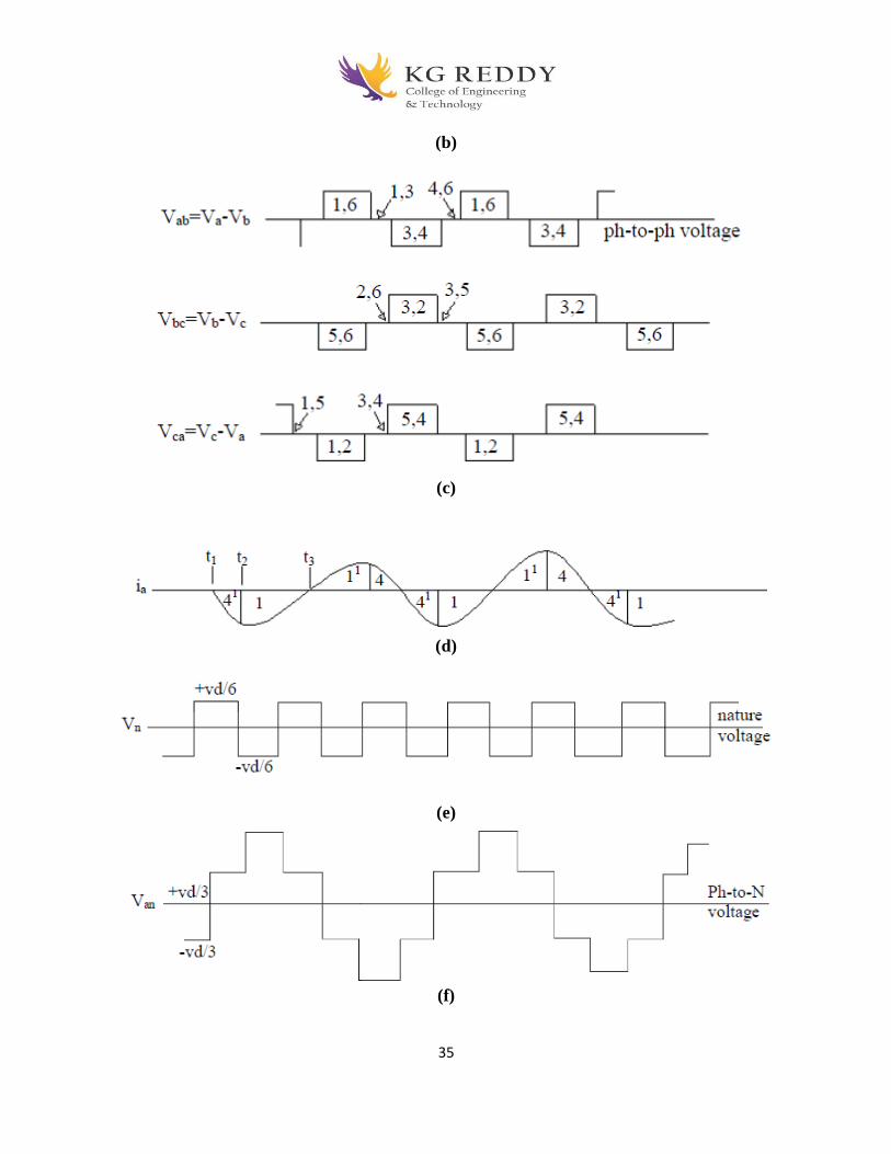
35
(b)
(c)
(d)
(e)
(f)

36
(g)
(h)
(i)
(j)
(k)

37
(l)
Fig 2.3 Three phase full wave bridge converter
Fig 2.3 (a) shows a three phase wave converter with six valves, i.e. (1-1') to (6-6') they
are designated in the order. 1 to 6 represents the sequence of valve operation in time. It consists
of three legs, 120º apart.
The three legs operate in a square wave mode; each valve alternately closes for 180º as in
the wave form of Fig 2.3 (b), Va, Vb and VC. These three square-wave waveform are the
voltages of A.C. buses a, b and c with respect to a D.C. capacitor midpoint “N” with peak
voltages of +Vd/2 and -Vd/2. The three phase legs have their timing 120º apart with respect to
each other to a 6-phase converter operation phase leg (3-6) switches 120º after phase leg (1-4)
and phase leg (5-2) switches 120º after phase (3-6), thus completing the cycle as shown by the
valve close-open sequence.
Fig 2.3 (c) shows the three phase-to-phase voltages Vab, Vbc and Vca, where Vab = Va-
Vb, Vbc = Vb-Vc and Vca = Vc-Va. These phase-to-phase voltages have 120º pulse width with
peak voltage magnitude of Vd. The periods of 60º, when the phase-to-phase voltages are zero,
represents the condition when two valves ON from the same group of the bridge.
The turn ON and turn OFF of the devices establish the wave forms of the A.C. bus
voltages in relation to the D.C. voltage, the current flows itself, is the result of the interaction of
the A.C. voltage with the D.C. system. Each converter phase-leg can handle resultant current
flow in either direction.
In fig 2.4 (d) A.C. current “Ia” in phase “a” with +ve current representing current from
A.C. to D.C. side.
2.Explain transformer connection for 12-pulse &24 pulse operation? TRANSFORMER CONNECTION FOR 12-PULSE OPERATION
The harmonics content of the phase to phase voltage and phase to neutral voltage are 30º out of phase. If this phase shift is corrected, then the phase to neutral voltage (Van) other than that of the harmonics order 12n±1 would be in phase opposition to those of the phase to phase voltage (Vab) and with 1/√3 times the amplitude.

38
In Fig 2.4 (a) if the phase to phase voltages of a second converter were connected to a
delta-connected secondary of a second transformer, with √3 times the turns compared to the star
connected secondary, and the pulse train of one converter was shifted by 30º with respect to the
other in order to bring “Vab” and “Van” to be in phase, the combined output voltage would have a
12-phase wave form, with harmonics of the order of 12n±1, i.e. 11th , 13th , 23rd , 25th …. and
with amplitudes of 1/11th, 1/13th, 1/23rd, 1/25th respectively, compared to the fundamental.

39
Fig 2.4 Transformer Connection for 12-Pulse Operation

40
Fig 2.4 (b): shows the two wave forms Van and Vab, adjusted for the transformer ratio
and one of them phase displaced by 30º. These two wave forms are then added to give the third
wave form, which is a 12-pulse wave form, closer to being a sine wave than each of the six-
phase wave form.
In the arrangement of Fig 2.4 (a), the two six-pulse converters, involving a total of six-
phase legs are connected in parallel on the same D.C. bus, and work together as a 12-pulse
converter. It is necessary to have two separate transformers, otherwise phase shift in the non 12-
pulse harmonics i.e. 5th, 7th, 17th, 19th …. In the secondaries it will result in a large circulating
current due to common core flux. To the non 12-pulse voltage harmonics, common core flux will
represent a near short circuit. Also for the same reason, the two primary side windings should not
be directly connected in parallel to the same three phase A.C. bus bars on the primary side.
Again this side becomes the non 12-pulse voltage harmonics i.e. 5th, 7th, 17th, 19th …. While
they cancel out looking into the A.C. system would be in phase for the closed loop. At the same
time harmonics will also flow in this loop, which is essentially the leakage inductance of the
transformers.
The circulating current of each non 12-pulse harmonics is given by: In/ I1 = 100/ (XT *
n²) Percent Where I1 is the nominal fundamental current, n is the relevant harmonic number, and
XT is the per unit transformer impedance of each transformer at the fundamental frequency. For
example, if XT is 0.15 per unit at fundamental frequency, then the circulating current for the fifth
harmonic will be 26.6%, seventh, 14.9%, eleventh, 5.5%, thirteenth, 3.9%, of the rated
fundamental current, and so on.
Therefore, it is necessary to connect the transformer primaries of two separate
transformers in series and connect the combination to the A.C. bus as shown in Fig 2.5 (a), with
the arrangement shown in Fig 2.4 (a), the 5th, 7th, 17th, 19th…. harmonics voltages cancel out,
and the two fundamental voltages add up, as shown in Fig 2.4 (b), and the combined unit
becomes a true 12-pulse converter.
TRANSFORMER CONNECTIONS FOR 24-PULSE AND 48-PULSE
OPERATION
Two 12-pulse converters phase shifted by 15º from each other can provide a 24-pulse
converter, with much lower harmonics on both A.C. and D.C. sides. Its A.C. output voltage
would have 24n±1 order of harmonics i.e. 23rd, 25th, 47th, 49th …. with magnitudes of 1/23rd,
1/25th, 1/47th, 1/49th……. respectively, of the fundamental A.C. voltage.
The question now is how to arrange this phase shift.
One approach is to provide 15º phase shift windings on the two transformers of one of the
two 12-pulse converters.
Another approach is to provide phase shift windings for (+7.5º) phase shift on the two
transformers of one 12-pulse converter and (-7.5º) on the two transformers of the other 12-pulse
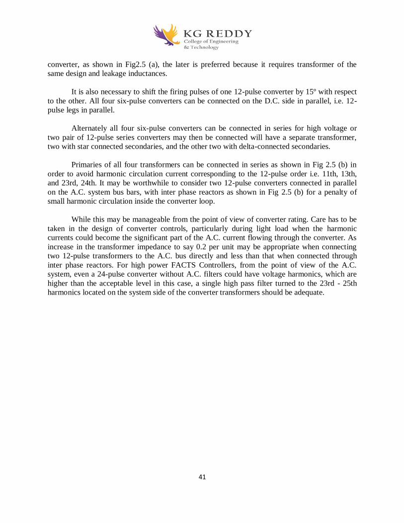
41
converter, as shown in Fig2.5 (a), the later is preferred because it requires transformer of the
same design and leakage inductances.
It is also necessary to shift the firing pulses of one 12-pulse converter by 15º with respect
to the other. All four six-pulse converters can be connected on the D.C. side in parallel, i.e. 12-
pulse legs in parallel.
Alternately all four six-pulse converters can be connected in series for high voltage or
two pair of 12-pulse series converters may then be connected will have a separate transformer,
two with star connected secondaries, and the other two with delta-connected secondaries.
Primaries of all four transformers can be connected in series as shown in Fig 2.5 (b) in
order to avoid harmonic circulation current corresponding to the 12-pulse order i.e. 11th, 13th,
and 23rd, 24th. It may be worthwhile to consider two 12-pulse converters connected in parallel
on the A.C. system bus bars, with inter phase reactors as shown in Fig 2.5 (b) for a penalty of
small harmonic circulation inside the converter loop.
While this may be manageable from the point of view of converter rating. Care has to be
taken in the design of converter controls, particularly during light load when the harmonic
currents could become the significant part of the A.C. current flowing through the converter. As
increase in the transformer impedance to say 0.2 per unit may be appropriate when connecting
two 12-pulse transformers to the A.C. bus directly and less than that when connected through
inter phase reactors. For high power FACTS Controllers, from the point of view of the A.C.
system, even a 24-pulse converter without A.C. filters could have voltage harmonics, which are
higher than the acceptable level in this case, a single high pass filter turned to the 23rd - 25th
harmonics located on the system side of the converter transformers should be adequate.
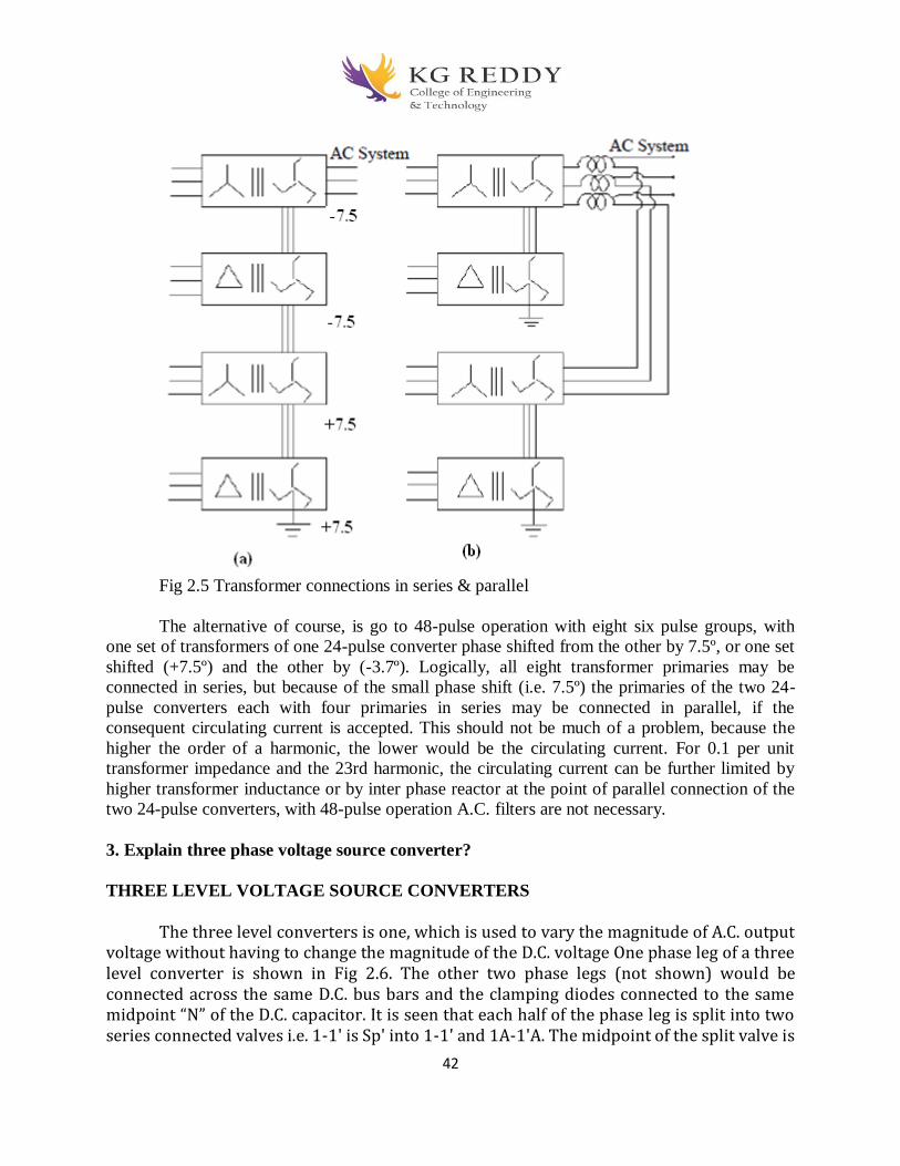
42
Fig 2.5 Transformer connections in series & parallel
The alternative of course, is go to 48-pulse operation with eight six pulse groups, with
one set of transformers of one 24-pulse converter phase shifted from the other by 7.5º, or one set
shifted (+7.5º) and the other by (-3.7º). Logically, all eight transformer primaries may be
connected in series, but because of the small phase shift (i.e. 7.5º) the primaries of the two 24-
pulse converters each with four primaries in series may be connected in parallel, if the
consequent circulating current is accepted. This should not be much of a problem, because the
higher the order of a harmonic, the lower would be the circulating current. For 0.1 per unit
transformer impedance and the 23rd harmonic, the circulating current can be further limited by
higher transformer inductance or by inter phase reactor at the point of parallel connection of the
two 24-pulse converters, with 48-pulse operation A.C. filters are not necessary.
3. Explain three phase voltage source converter?
THREE LEVEL VOLTAGE SOURCE CONVERTERS
The three level converters is one, which is used to vary the magnitude of A.C. output voltage without having to change the magnitude of the D.C. voltage One phase leg of a three level converter is shown in Fig 2.6. The other two phase legs (not shown) would be connected across the same D.C. bus bars and the clamping diodes connected to the same midpoint “N” of the D.C. capacitor. It is seen that each half of the phase leg is split into two series connected valves i.e. 1-1' is Sp' into 1-1' and 1A-1'A. The midpoint of the split valve is

43
connected by diodes D1 and D2 to the midpoint “N” as shown on the phase of it; this may seem like doubling the number of valves from two to four per phase leg, in addition to providing two extra diode valves. However, doubling the number of valves with the same voltage rating would double the D.C. voltage and hence the power capacity of the converter. Thus only the addition of the diode clamping valves D1 and D4 per phase leg as in Fig 2.6 adds to the converter cost. If the converter is a high voltage converter with devices in series, then the number of main devices would be about the same. A diode clamp at the midpoint may also help to ensure a more voltage sharing between the two valve halves.
Fig 2.6 Three level Voltage source converter
Fig 2.7 shows output voltage corresponding to one three level phase leg. The first wave
form shows a full 180º square wave obtained by the closing of devices 1 and 1A to give (+Vd/2)
for 180º and the closing of valves 4 and 4A for180º to give (-Vd/2) for 180º . Now consider
second voltage wave form in Fig 2.7 in which upper device 1 is OFF and device 4A is ON an
angle α earlier than they were due in the 180º square wave operation. This leaves only device 1A
and 4A ON, which in combination with diodes D1 and D2, clamp the phase voltage Va to zero
with respect to the D.C. midpoint “N” regardless of which way the current is flowing, this
continues for a period 2α until device 1A is turned OFF and device 4 is turned ON and the
voltage jumps to (-Vd/2) with both the lower devices 4 and 4A turned ON and both the upper
devices 1 and 1A turned OFF and so ON. The angle α is variable and the output voltage Va is
made up of σ = 180º - 2αº square waves. This variable period “σ” per half cycle allows the
voltage Va to be independently variable with a fast response. It is seen that devices 1A and 4A
are turned ON for 180º during each cycle devices 1 and 4 are turned ON for σ = 180º - 2αº
during each cycle, while diodes D1 and D4 conduct for 2αº = 180ºσ each cycle. The converter is
referred to as three level because the D.C. voltage has three levels i.e. (-Vd/2), 0 and (+Vd/2).
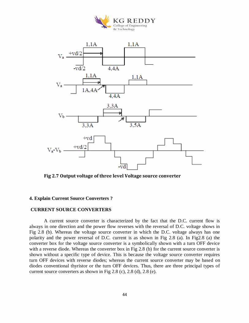
44
Fig 2.7 Output voltage of three level Voltage source converter
4. Explain Current Source Converters ?
CURRENT SOURCE CONVERTERS
A current source converter is characterized by the fact that the D.C. current flow is
always in one direction and the power flow reverses with the reversal of D.C. voltage shows in
Fig 2.8 (b). Whereas the voltage source converter in which the D.C. voltage always has one
polarity and the power reversal of D.C. current is as shown in Fig 2.8 (a). In Fig2.8 (a) the
converter box for the voltage source converter is a symbolically shown with a turn OFF device
with a reverse diode. Whereas the converter box in Fig 2.8 (b) for the current source converter is
shown without a specific type of device. This is because the voltage source converter requires
turn OFF devices with reverse diodes; whereas the current source converter may be based on
diodes conventional thyristor or the turn OFF devices. Thus, there are three principal types of
current source converters as shown in Fig 2.8 (c), 2.8 (d), 2.8 (e).

45
46
Fig 2.8 Current source converters
Diode Rectifier or Diode Converter Fig 2.8 (c) represents the diode converter, which simply converts A.C. voltage to D.C. voltage and utilizes A.C. system voltage for commutating of D.C. current from one valve to another. Obviously the diode based line commutating converter just converts A.C. power to D.C. power without any control and also in doing so consumes some reactive power on the A.C. side. Thyristor Line Commutated Converter It is based on conventional thyristor with gate turn ON but without gate turn OFF capability as in Fig 2.8 (d): utilizes A.C. system voltage for commutation of current from one valve to another. This converter can convert and controls active power in either direction, but in doing so consumes reactive power on the A.C. side. It can not supply reactive power to the A.C. system. Self Commutated Converter It is based on turn OFF devices like (GTOs, MTOs, IGBTs, etc) in which commutation of current from valve to valve takes place with the device turn OFF action and provision of A.C. capacitors to facilitate transfer of current from valve to valve as in Fig 2.8 (e).Where as in a voltage source converter the commutation of current is supported by a stiff D.C. bus with D.C. capacitors provide a stiff A.C. bus for supplying the fact changing current pulses needed for the commutations. It also supplies or consumes the reactive power. 5. Compare Current Source Converters and Voltage Source Converters? Comparison between Current Source Converters and Voltage Source Converters Current source converters in which direct current always has one polarity and the
power reversal takes place through reversal of D.C. voltage polarity. Whereas voltage source converters in which the D.C. voltage always has one polarity, and the power reversal takes place through reversal of D.C. current polarity.
Conventional Thyristor-based converters, being without turn OFF capability, can only be
current source converters. Whereas turn OFF device based converters can be of either
type i.e. current source or voltage source converter.
Diode based current source converters are the lowest cost converters, if control of active
power by the converter is not required. Whereas the same type of voltage source
converters are expensive.
If the leading reactive power is not required, then a conventional Thyristor based current
source converter provides a low cost, converter with active power control. But for the
same purpose Voltage source converter is costly.
47
The current sourced converter does not have high short circuit current, where as the
voltage source converter has high short circuit current.
For current source converters, the rate of rise of fault current during external or internal
faults is limited by the d.c reactor. For the voltage source converters the capacitor
discharge current would rise very rapidly and can damage the valves.
The six-pulse current source converter does not generate 3rd harmonic voltage, where as
voltage source converter, it generates.
The transformer primaries connected to current source converter of 12-pulse should not
be connected in series, where as the voltage source converter for the same purpose may
be connected in series for the cancellation of harmonics.
In a current stiff converter, the valves are not subject to high dv/dt, due to the presence of
A.c capacitor, where as in voltage source converter it can be available.
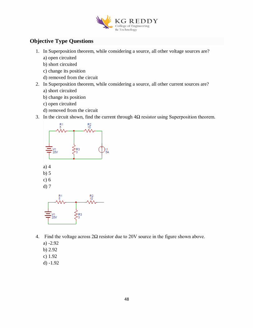
48
Objective Type Questions
1. In Superposition theorem, while considering a source, all other voltage sources are?
a) open circuited
b) short circuited
c) change its position
d) removed from the circuit
2. In Superposition theorem, while considering a source, all other current sources are?
a) short circuited
b) change its position
c) open circuited
d) removed from the circuit
3. In the circuit shown, find the current through 4Ω resistor using Superposition theorem.
a) 4
b) 5
c) 6
d) 7
4. Find the voltage across 2Ω resistor due to 20V source in the figure shown above.
a) -2.92
b) 2.92
c) 1.92
d) -1.92
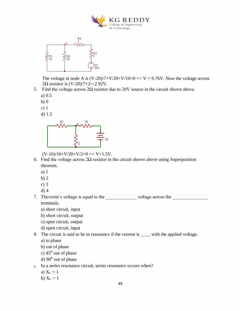
49
The voltage at node A is (V-20)/7+V/20+V/10=0 => V = 9.76V. Now the voltage across
2Ω resistor is (V-20)/7×2=-2.92V.
5. Find the voltage across 2Ω resistor due to 20V source in the circuit shown above.
a) 0.5
b) 0
c) 1
d) 1.5
(V-10)/10+V/20+V/2=0 => V=1.5V.
6. Find the voltage across 2Ω resistor in the circuit shown above using Superposition
theorem.
a) 1
b) 2
c) 3
d) 4
7. Thevenin’s voltage is equal to the _____________ voltage across the _______________
terminals.
a) short circuit, input
b) short circuit, output
c) open circuit, output
d) open circuit, input
8. The circuit is said to be in resonance if the current is ____ with the applied voltage.
a) in phase
b) out of phase
c) 45⁰ out of phase
d) 90⁰ out of phase
9. In a series resonance circuit, series resonance occurs when?
a) XL = 1
b) XC = 1

50
c) XL = XC
d) XL = -XC
10. As XL = XC in a series resonance circuit, the impedance is_________.
a) purely capacitive
b) purely inductive
c) purely resistive
d) capacitive and inductive
Fill in the Blanks
1. The voltage across the LC combination in a series RLC circuit is_____________
2. __________the current flowing between terminals A and B of the circuit shown below.
3. Find the current flowing between terminals A and B _____________
4. For the Reciprocity Theorem to satisfy the ratio of response to excitation before and after
the source is replaced should be__________
5. The maximum power is delivered from a source to its load when the load resistance is
______ the source resistance.
6. Tellegen’s Theorem is valid for _____ network?
7. According to Millman’s Theorem, if there are n voltage sources with n internal
resistances respectively, are in parallel, then these sources are replaced by__________
8. In the question above, the value of equivalent voltage source is______
9. If there are 8 nodes in network, we can get ____ number of equations in the nodal
analysis.
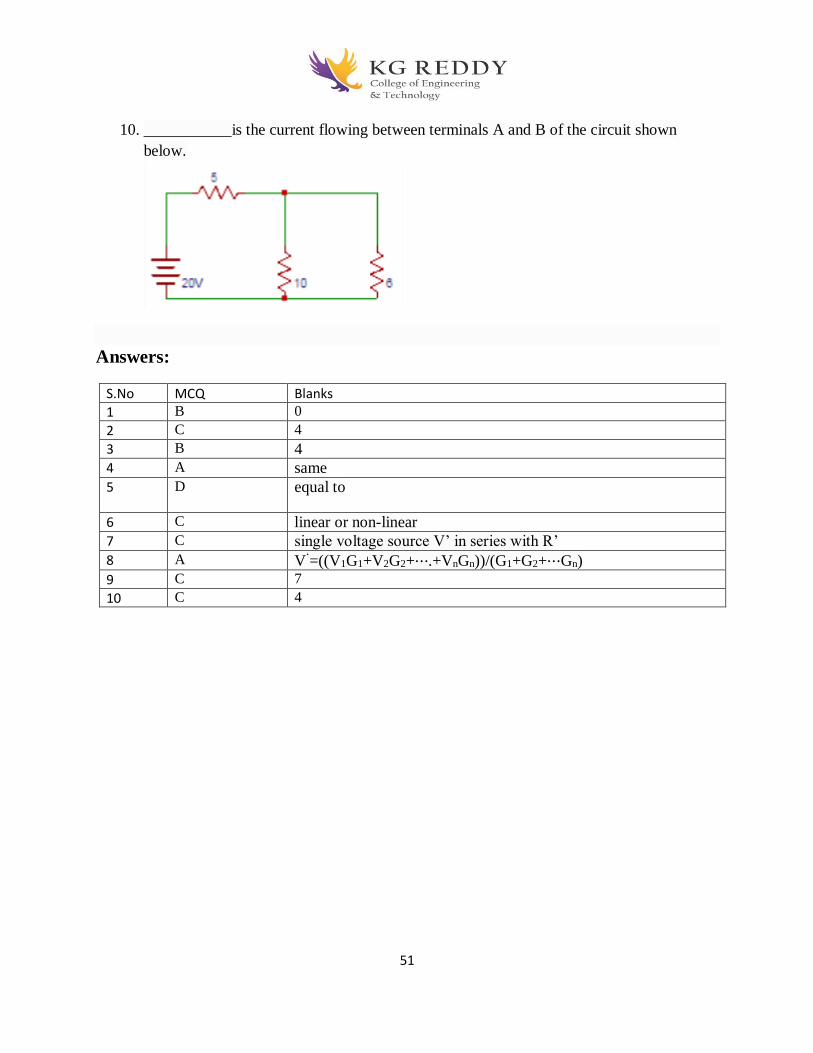
51
10. ___________is the current flowing between terminals A and B of the circuit shown
below.
Answers:
S.No MCQ Blanks
1 B 0
2 C 4
3 B 4
4 A same
5 D equal to
6 C linear or non-linear
7 C single voltage source V’ in series with R’
8 A V‘=((V1G1+V2G2+⋯.+VnGn))/(G1+G2+⋯Gn)
9 C 7
10 C 4
52
UNIT-III
SHUNT AND SERIES COMPENSATION
2-Marks Question and answers
1. List the disadvantage of fixed series compensation?
It is effective only during heavy loadsWhenever an outage occurs on a line, with series
compensation, the series compensation is removed. This may cause overloading of other parallel
lines If series compensation is added to an existing system, it is generally necessary to have it on
all the lines in parallel. One major drawback in the series capacitance compensation is that special
productive devices are required to protect the capacitors and bypass the high current produced
when a SC occurs
2. What is meant by thyristor switched capacitor?
TCSC is a capacitive reactance compensator, which consists of series capacitor bank shunted by a
thyristor-controlled reactor.
3. Define the term Static VAR compensator?
The SVC is a shunt device of FACTS group using power electronics to control power flow and
improve transient stability on power grids. The SVC regulates voltage at its terminals by
controlling the amount of reactive power injected into or absorbed from the power system.
4. What are the diff types of compensation schemes? What are the diff power electronic
switching devices?
Mainly two types of compensation are carried out, Load compensation Line compensation
SCR MOSFET GTO IGBT DOIDE BJT
5.What is best location for SVC?
Location of SVC strongly affects controllability of swing modes. In general the best location is
at a point where voltage swings are greatest. Normally, the midpoint of a transmission line
between the two areas is a good location.

53
3-Marks Question and answers
1. Compare fixed series compensation and fixed shunt compensation.?
Voltage boost due to shunt compensators is uniform throughout the line. Power factor will be
improved by the shunt capacitor whereas, series compensator improves power system stability
limit Protection required for the series compensator is more compared to shunt compensator.
Amount of voltage boost by the series capacitor is more
1. Define voltage regulation of a transformer?
When a transformer is loaded with a constant primary voltage,the secondary voltage decreases
for lagging PF load, and increases for leading PF load because of its internal resistance and
leakage reactance. The change in secondary terminal voltage from no load to full load
expressed as a percentage of no load or full load voltage is termed as regulation.
%regulation =E2-V2/E2*100
V2>E2 for leading p.f load
V2<E2 for lagging p.f load
2. Define all day efficiency of a transformer?
It is computed on the basis of energy consumed during a certain period, usually a day of 24 hrs.
All day efficiency=output in kWh/input in kWh for 24 hrs.
3. Why transformers are rated in kVA?
Copper loss of a transformer depends on current & iron loss on voltage. Hence total losses
depend on Volt-Ampere and not on PF. That is why the rating of transformers is in kVA and
not in kW.
4. Explain VAR generators?
Hybrid VAR Generators, SVC and STATCOM
The converter-based var generator can generate or absorb the same amount of
maximum reactive power; in other words, it has the same control range for
capacitive and inductive var output.
However, many applications may call for a different var generation and
absorption range.
This can simply be achieved by combining the converter with either fixed
and/or thyristor-switched capacitors and/or reactors.
The combination of a converter-based var generator with a fixed capacitor is
shown in below Figure.

54
This arrangement can generate vars in excess of the rating of the converter,
shifting the operating range into the capacitive region, as illustrated by the
associated V-I characteristic shown in Figure (b).
5marks questions and answers
1. Explain the Objectives of Shunt Compensation?
Objectives of Shunt Compensation
steady-state transmittable power can be increased.
voltage profile along the line controlled by appropriate reactive shunt
compensation.
shunt connected, fixed or mechanically switched reactors are applied to
minimize line overvoltage under light load conditions,
shunt connected fixed or mechanically switched capacitors are applied to
maintain voltage levels under heavy load conditions.
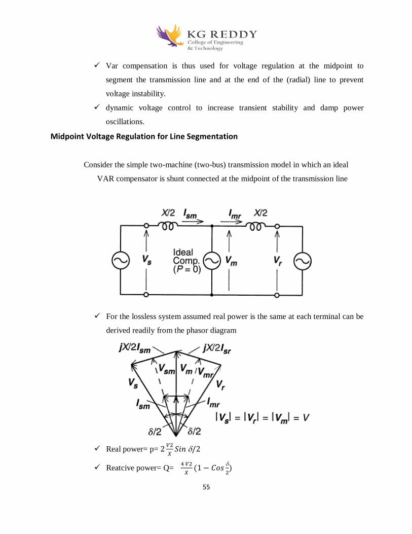
55
Var compensation is thus used for voltage regulation at the midpoint to
segment the transmission line and at the end of the (radial) line to prevent
voltage instability.
dynamic voltage control to increase transient stability and damp power
oscillations.
Midpoint Voltage Regulation for Line Segmentation
Consider the simple two-machine (two-bus) transmission model in which an ideal
VAR compensator is shunt connected at the midpoint of the transmission line
For the lossless system assumed real power is the same at each terminal can be
derived readily from the phasor diagram
Real power= p= 2
𝑉2
𝑋𝑆𝑖𝑛 /2
Reatcive power= Q= 4 𝑉2
𝑋(1 − 𝐶𝑜𝑠
2)
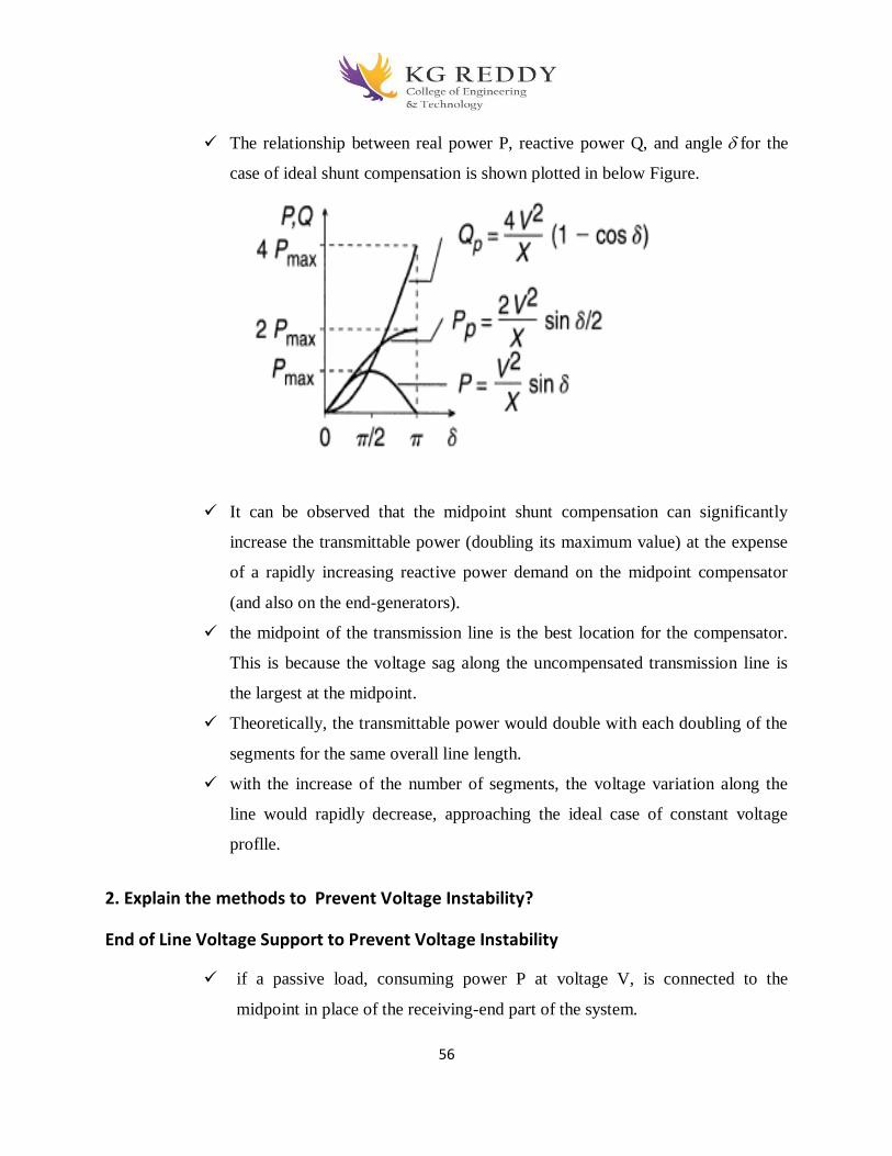
56
The relationship between real power P, reactive power Q, and angle for the
case of ideal shunt compensation is shown plotted in below Figure.
It can be observed that the midpoint shunt compensation can significantly
increase the transmittable power (doubling its maximum value) at the expense
of a rapidly increasing reactive power demand on the midpoint compensator
(and also on the end-generators).
the midpoint of the transmission line is the best location for the compensator.
This is because the voltage sag along the uncompensated transmission line is
the largest at the midpoint.
Theoretically, the transmittable power would double with each doubling of the
segments for the same overall line length.
with the increase of the number of segments, the voltage variation along the
line would rapidly decrease, approaching the ideal case of constant voltage
proflle.
2. Explain the methods to Prevent Voltage Instability?
End of Line Voltage Support to Prevent Voltage Instability
if a passive load, consuming power P at voltage V, is connected to the
midpoint in place of the receiving-end part of the system.

57
Without compensation the voltage at the midpoint (which is now the receiving
end) would vary with the load (and load power factor).
A simple radial system with feeder line reactance of X and load impedance
Z,is shown in Figure (a) together with the normalized terminal voltage ,
versus power P plot at various load power factors, ranging from 0.8 lag and
0.9 lead.
The "nose-point" at each plot given for a specific power factor represents the
voltage instability corresponding to that system condition
The voltage stability limit decreases with inductive loads and increases with
capacitive loads.
The V, versus P plots shown, clearly indicate that shunt reactive
compensation can effectively increase the voltage stability limit by supplying
the reactive load and regulating the terminal voltage (V – Vr = 0) as
illustrated in Figure (b).
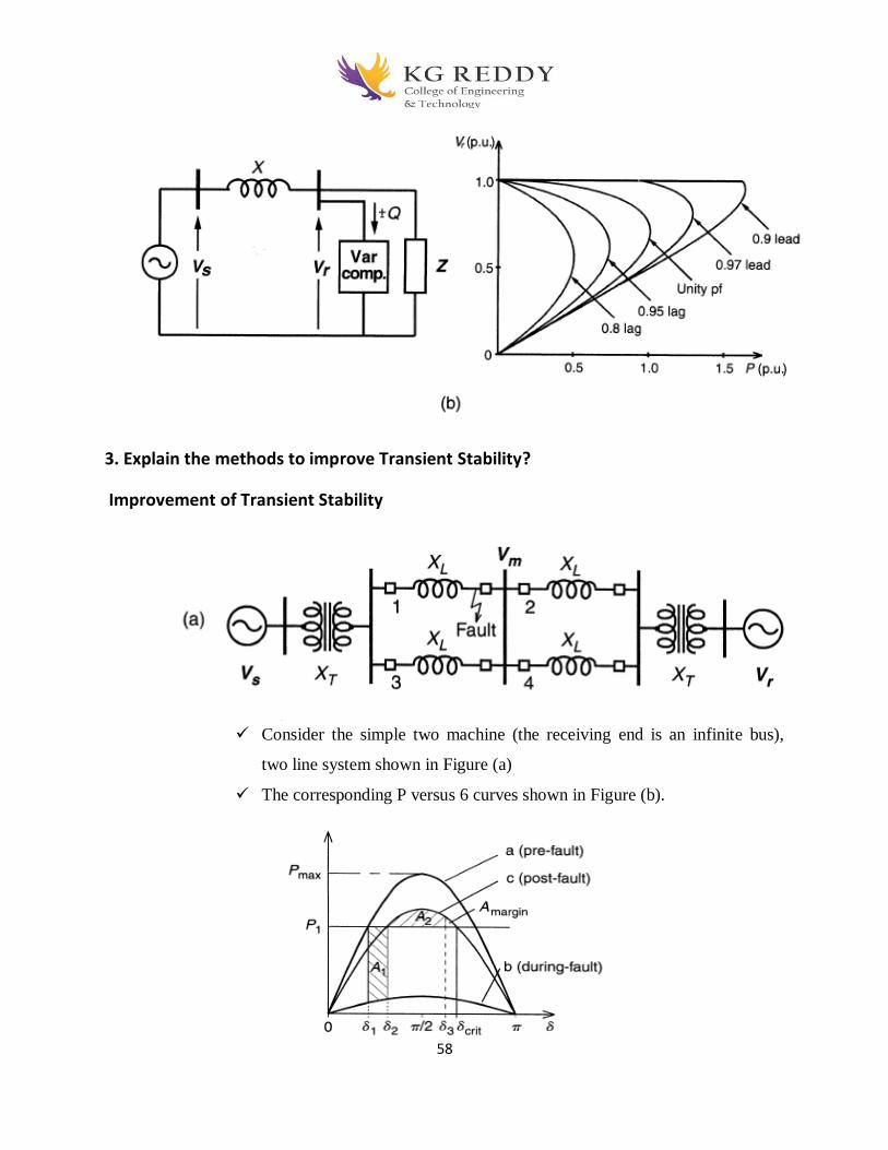
58
3. Explain the methods to improve Transient Stability?
Improvement of Transient Stability
Consider the simple two machine (the receiving end is an infinite bus),
two line system shown in Figure (a)
The corresponding P versus 6 curves shown in Figure (b).
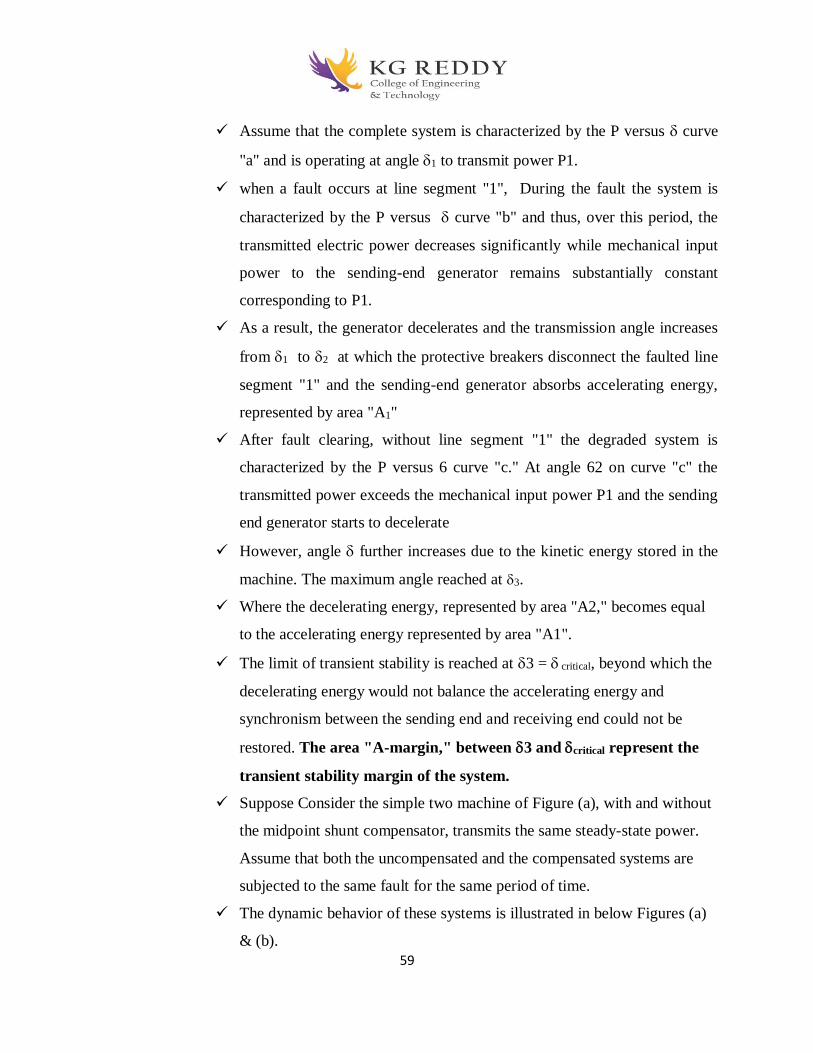
59
Assume that the complete system is characterized by the P versus curve
"a" and is operating at angle 1 to transmit power P1.
when a fault occurs at line segment "1", During the fault the system is
characterized by the P versus curve "b" and thus, over this period, the
transmitted electric power decreases significantly while mechanical input
power to the sending-end generator remains substantially constant
corresponding to P1.
As a result, the generator decelerates and the transmission angle increases
from 1 to 2 at which the protective breakers disconnect the faulted line
segment "1" and the sending-end generator absorbs accelerating energy,
represented by area "A1"
After fault clearing, without line segment "1" the degraded system is
characterized by the P versus 6 curve "c." At angle 62 on curve "c" the
transmitted power exceeds the mechanical input power P1 and the sending
end generator starts to decelerate
However, angle further increases due to the kinetic energy stored in the
machine. The maximum angle reached at 3.
Where the decelerating energy, represented by area "A2," becomes equal
to the accelerating energy represented by area "A1".
The limit of transient stability is reached at 3 = critical, beyond which the
decelerating energy would not balance the accelerating energy and
synchronism between the sending end and receiving end could not be
restored. The area "A-margin," between 3 and critical represent the
transient stability margin of the system.
Suppose Consider the simple two machine of Figure (a), with and without
the midpoint shunt compensator, transmits the same steady-state power.
Assume that both the uncompensated and the compensated systems are
subjected to the same fault for the same period of time.
The dynamic behavior of these systems is illustrated in below Figures (a)
& (b).

60
Comparison of Figures (a) and (b) clearly shows a substantial increase in
the transient stability margin the ideal midpoint compensation.
Power Oscillation Damping
In the case of an under-damped power system, any minor disturbance can cause
the machine angle to oscillate around its steady-state value at the natural
frequency of the total electromechanical system.
The angle oscillation, of course, results in corresponding power oscillation around
the steady-state power transmitted.
The lack of sufficient damping can be a major problem in some power systems
and, in some cases; it may be the limiting factor for the transmittable power.
Since power oscillation is a sustained dynamic event, it is necessary to vary the
applied shunt compensation, and thereby the (midpoint) voltage of the

61
transmission line, to counteract the accelerating and decelerating swings of the
disturbed machine(s).
When the rotationally oscillating generator accelerates and angle increases
(d/dt > 0), the electric power transmitted must be increased to compensate for the
excess mechanical input power.
The requirements of var output control, and the process of power oscillation
damping, is illustrated by the following waveforms.
Waveforms in Figure (a) show the undamped and damped oscillations of angle
around the steady-state value 0.
Waveforms in Figure (b) show the undamped and damped oscillations of the
electric power P around the steady-state value P0". (The momentary drop in power
shown at the beginning of the waveform represents an assumed disturbance that
initiated the oscillation.)
Waveform c shows the reactive power output Qo of the shunt-connected var
compensator.

62
5. Explain the Methods of Controllable VAR Generation?
Methods of Controllable VAR Generation
Capacitors generate and reactors (inductors) absorb reactive power when
connected to an ac power source. They have been used with mechanical
switches for controlled var generation and absorption since the early days of ac
power transmission.
Continuously variable var generation or absorption for dynamic system
compensation was originally provided by over- or under-excited rotating
synchronous machines
Now a days for controlled var generation Saturating reactors in conjunction with
fixed capacitors are used.

63
There are three ways of controllable VAR generation
Variable Impedance Type Static VAR Generators
Switching Converter Type VAR Generators
Hybrid Var Generators, SVC and STATCOM
Variable Impedance Type Static Var Generators
There are two types of variable impedance type static VAR generators. They are
I. The thyristor controlled reactor (TCR)
II. The thyristor-switched capacitor. (TSC)
III. Fixed Capacitor, Thyristor-Controlled Reactor Type VAR Generation
IV. Thyristor-Switched Capacitor, Thyristor-Controlled Reactor Type VAR
Generator.
I.The thyristor controlled reactor (TCR)
An elementary single-phase thyristor-controlled reactor (TCR) is shown
in Figure (a).
It consists of a fixed (usually air-core) reactor of inductance L, and a
bidirectional thyristor valve (or switch) sw.
The current in the reactor can be controlled from maximum (thyristor
valve closed) to zero (thyristor valve open) by the method of firing
delay angle control.
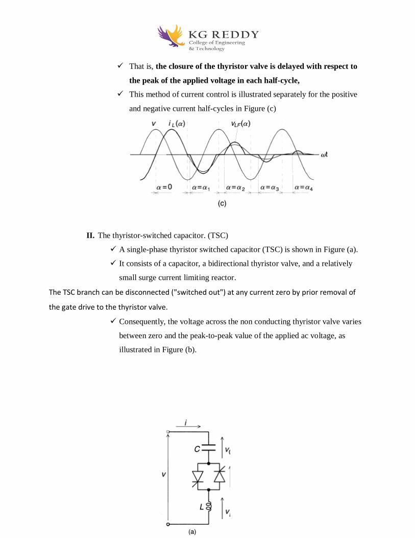
64
That is, the closure of the thyristor valve is delayed with respect to
the peak of the applied voltage in each half-cycle,
This method of current control is illustrated separately for the positive
and negative current half-cycles in Figure (c)
II. The thyristor-switched capacitor. (TSC)
A single-phase thyristor switched capacitor (TSC) is shown in Figure (a).
It consists of a capacitor, a bidirectional thyristor valve, and a relatively
small surge current limiting reactor.
The TSC branch can be disconnected ("switched out") at any current zero by prior removal of
the gate drive to the thyristor valve.
Consequently, the voltage across the non conducting thyristor valve varies
between zero and the peak-to-peak value of the applied ac voltage, as
illustrated in Figure (b).
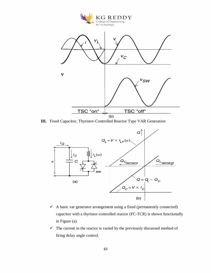
65
III. Fixed Capacitor, Thyristor-Controlled Reactor Type VAR Generation
A basic var generator arrangement using a fixed (permanently connected)
capacitor with a thyristor-controlled reactor (FC-TCR) is shown functionally
in Figure (a).
The current in the reactor is varied by the previously discussed method of
firing delay angle control.

66
The fixed capacitor in practice is usually substituted, fully or partially, by a
fllter network that has the necessary capacitive impedance at the fundamental
frequency to generate the reactive power required, but it provides a low
impedance at selected frequencies to shunt the dominant harmonics produced
by the TCR.
IV. Thyristor-Switched Capacitor, Thyristor-Controlled Reactor Type VAR Generator.
The thyristor-switched capacitor, thyristor-controlled reactor (TSC-TCR) type compensator was
developed primarily for dynamic compensation of power transmission systems with the
intention of minimizing standby losses and providing increased operating flexibility.
A basic single-phase TSC-TCR arrangement is shown in Figure (a). For a
given capacitive output range, it typically consists of n TSC branches and
o
n
e
T
C
R
.
T
h
e
number of branches, n, is determined by practical considerations that
include the operating voltage level, maximum var output, current rating of
the thyristor valves, bus work and installation cost, etc. Of course, the
inductive range also can be expanded to any maximum rating by employing
additional TCR branches.
Switching Converter Type VAR Generators
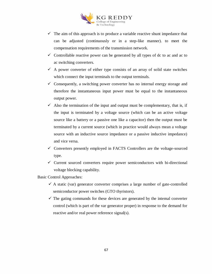
67
The aim of this approach is to produce a variable reactive shunt impedance that
can be adjusted (continuously or in a step-like manner). to meet the
compensation requirements of the transmission network.
Controllable reactive power can be generated by all types of dc to ac and ac to
ac switching converters.
A power converter of either type consists of an array of solid state switches
which connect the input terminals to the output terminals.
Consequently, a switching power converter has no internal energy storage and
therefore the instantaneous input power must be equal to the instantaneous
output power.
Also the termination of the input and output must be complementary, that is, if
the input is terminated by a voltage source (which can be an active voltage
source like a battery or a passive one like a capacitor) then the output must be
terminated by a current source (which in practice would always mean a voltage
source with an inductive source impedance or a passive inductive impedance)
and vice versa.
Converters presently employed in FACTS Controllers are the voltage-sourced
type.
Current sourced converters require power semiconductors with bi-directional
voltage blocking capability.
Basic Control Approaches:
A static (var) generator converter comprises a large number of gate-controlled
semiconductor power switches (GTO thyristors).
The gating commands for these devices are generated by the intemal converter
control (which is part of the var generator proper) in response to the demand for
reactive and/or real power reference signal(s).
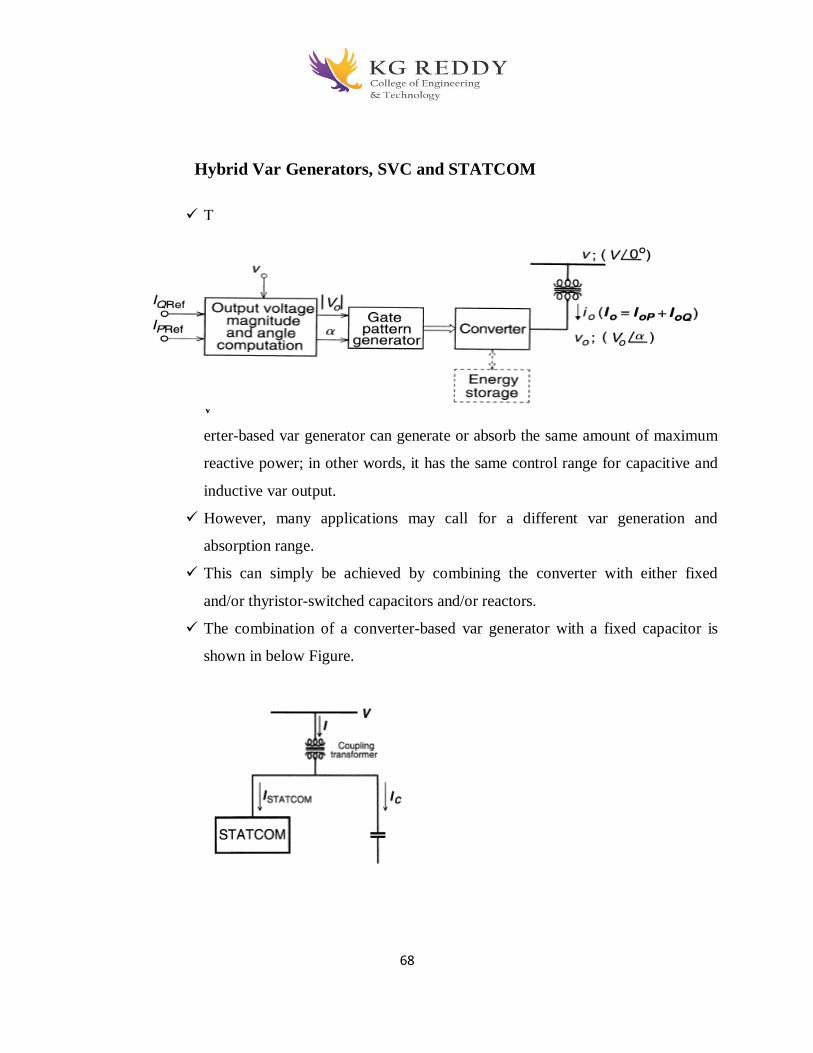
68
Hybrid Var Generators, SVC and STATCOM
T
h
e
c
o
n
v
erter-based var generator can generate or absorb the same amount of maximum
reactive power; in other words, it has the same control range for capacitive and
inductive var output.
However, many applications may call for a different var generation and
absorption range.
This can simply be achieved by combining the converter with either fixed
and/or thyristor-switched capacitors and/or reactors.
The combination of a converter-based var generator with a fixed capacitor is
shown in below Figure.

69
This arrangement can generate vars in excess of the rating of the converter,
shifting the operating range into the capacitive region, as illustrated by the
associated V-I characteristic shown in Figure (b).
Objective Type Questions
1. The primary and secondary of a transformer are ________ coupled but _______ connected.
a) Magnetically, not electrically
b) electrically, not magnetically
c) magnetically, also magnetically
d) electrically, also electrically
2. We can employ transformers for a power range of
a) lower and higher values
b) lower values
c) higher values
d) medium values
3. A transformer has comparatively much higher efficiency than a similar induction machine due
to
a) small air gaps
b) no moving parts
c) strong coupling
d) all of the mentioned
4. It was needed that to isolate dc noise coming from the transmitted signal, to attain the same
which machine can be used without suffering significant loss
a) transformer
b) dc machine
c) induction machine
d) stepper motor
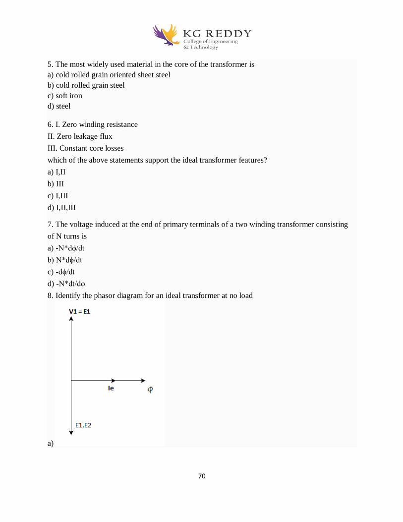
70
5. The most widely used material in the core of the transformer is
a) cold rolled grain oriented sheet steel
b) cold rolled grain steel
c) soft iron
d) steel
6. I. Zero winding resistance
II. Zero leakage flux
III. Constant core losses
which of the above statements support the ideal transformer features?
a) I,II
b) III
c) I,III
d) I,II,III
7. The voltage induced at the end of primary terminals of a two winding transformer consisting
of N turns is
a) -N*dϕ/dt
b) N*dϕ/dt
c) -dϕ/dt
d) -N*dt/dϕ
8. Identify the phasor diagram for an ideal transformer at no load
a)
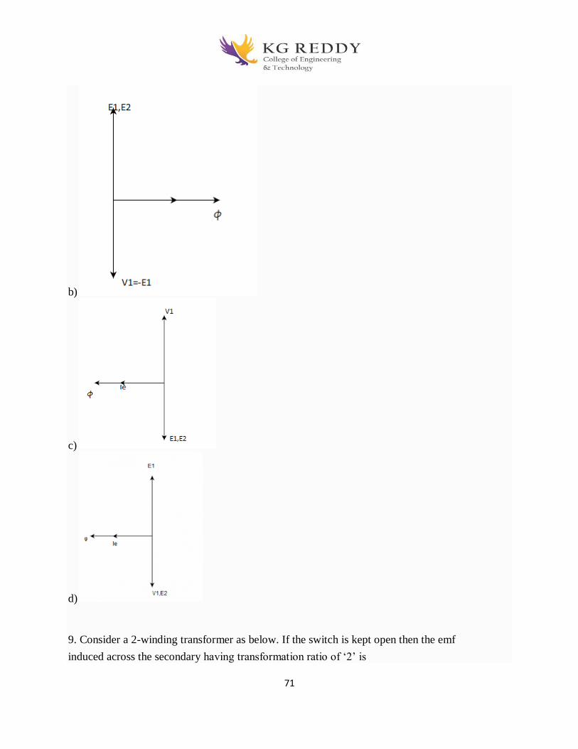
71
b)
c)
d)
9. Consider a 2-winding transformer as below. If the switch is kept open then the emf
induced across the secondary having transformation ratio of ‘2’ is

72
a) zero
b) 2E1
c) E/2
d) E1
10. Which of the below mentioned losses occur in a transformer?
a) Hysteresis losses ;Eddy current losses; Dielectric losses; Stray load losses
b) Hysteresis losses ;Eddy current losses;
c) Dielectric losses; Stray load losses
d) Hysteresis losses ;Eddy current losses; Stray load losses
Fill In The Blanks
1. Power required during the open circuit and short circuit test is ____________incurring in the
transformer
2. OC test is performed on the l.v. side of the transformer because __________will have lower
stress on the insulation and no damage will occur.
3. To circulate the rated current in the winding, we should opt for ________of the current so
that winding will not damage.
4. If the frequency at the primary supply is varied gradually, then the secondary terminal
voltage will _____________
5. The magnetizing current does not depend on the _________________fed to it.
6. The power and the KVA of an ideal transformer always remains same assuming negligible
_____________
7. If the magnetization is non linear in nature then it will cause a saturation in the core and
harmonics will be introduced to cause _______________
8. Impedance is transformed in square of the _______________
9. Laminations provide larger area so that the current path____ and current ____________
10. CRGO has magnetization in the rolling direction and ___________and very high
permeability than present materials.
Answers:

73
S.No MCQ Blanks
1 A Losses
2 A The l.v. winding 3 D lower value
4 A not change
5 A frequency of the supply
6 A impedances
7 A humming sounds
8 A Turns-ratio
9 A Increases, reduces
10 A low core losses
UNIT-IV
STATCOM
2-Marks Question and answers
1.Define the term static VAR compensator (SVC).?
Static VAR Compensator is an electrical device, commonly known as SVCs, or shunt connected
devices, vary the reactive power output by controlling or switching the reactive impedance
components by means of power electronics devices. The SVC regulates voltage at its terminals by
controlling the amount of reactive power injected into or absorb from the power system. The term
“STATIC” refers to the fact that the SVC has no moving parts. Hence it requires low maintenance.
2.What are advantages of slope in the dynamic characteristics of SVC?
Substantially reduces the reactive power rating of the SVC for achieving nearly the same control
objectives. Prevents the SVC from reaching its reactive power limits too frequently Facilitates
the sharing of reactive power among multiple compensators operating in parallel
3. What is the best location for SVC? Justify.
It has been proven that the midpoint of the transmission line is the optimal location of SVC. This
proof is based on the linear load which is not valid practically For nonlinear load model it was
found that the best location for advanced Static VAR compensator close to the receiving end
74
where the wide range of reactive power could be controlled.
4. What are the general characteristics of SVCs?
The lowering of maintenance requirements due to the absence of rotating parts The very fast
control response time The feasibility of individual phase control Reduced losses Highly
reliable
5. List the Advantages of SVC? Define voltage stability?
Higher capacity Faster and more reliable Simple operation Improves steady state stability
and transient stability It is the ability of a power system to maintain steady acceptable voltages at
all buses in the system under normal operating conditions and after being subjected to a
disturbance1.
3-Marks Question and answers
1. Explain the real power compensation?
Real Power Compensation.
In contrast to the series capacitor, which functions in the transmission circuit as a
reactive impedance and as such is only able to exchange reactive power, the SSSC
can negotiate both reactive and active power with the ac system, simply by
controlling the angular position of the injected voltage with respect to the line current.
However, as explained previously, the exchange of active power requires that the dc
terminal of the SSSC converter be coupled to an energy source/sink, or suitable
energy storage.
The capability of the SSSC to exchange active power has significant application
potential. One important application is the simultaneous compensation of both the
reactive and resistive components of the series line impedance in order to keep the
XIR ratio high.
2. What is meant by armature reaction in alternators?
75
The interaction between flux set up by the current carrying armature conductors and the main
field flux is defined as the armature reaction.
1. What do you mean by synchronous reactance?
It is the sum of the leakage reactance X1 and armature reactance Xa
Xs = X1 + Xa
1. Mention the methods of starting of 3-phase synchronous motor.
a. A D.C motor coupled to the synchronous motor shaft.
b. A small induction motor coupled to its shaft.(pony method)
c. Using damper windings –started as a squirrel cage induction motor.
2. What are the principal advantages of rotating field system type of construction of
synchronous machines?
Form Stationary connection between external circuit and system of conditions enable the
machine to handle large amount of volt-ampere as high as 500 MVA. The relatively small
amount of power required for field system can be easily supplied to the rotating field system via
slip rings and brushes. More space is available in the stator part of the machine for providing
more insulation to the system of conductors. Insulation to stationary system of conductors is not
subjected to mechanical stresses due to centrifugal action. Stationary system of conductors can
easily be braced to prevent deformation.
It is easy to provide cooling arrangement.
5marks question and answers 1. Explain the Objectives of Series Compensation?
Shunt compensation is ineffective in controlling the actual transmitted power
which, at a defined transmission voltage, is ultimately determined by the series
line impedance and the angle between the end voltages of line.
The ac power transmission over long lines was primarily limited by the series
reactive impedance of the line.
Series capacitive compensation was introduced decades ago to cancel a portion
of the reactive line impedance and thereby increase the transmittable power.

76
It can be applied to achieve full utilization of transmission assets by controlling
the power flow in the lines, preventing loop flows and, with the use of fast
controls, minimizing the effect of system disturbances, thereby reducing
traditional stability margin requirements.
2.Explain the Voltage Stability?
Voltage Stability
Series capacitive compensation can also be used to reduce the series reactive
impedance to minimize the receiving-end voltage variation and the possibility
of voltage collapse.
A simple radial system with feeder line reactance X, series compensating
reactance Xs, and load impedance Z is shown in Figure 6.2(a).
The corresponding normalized terminal voltage V, versus power P plots, with
unity power factor load at 0, 50, and 75% of series capacitive compensation,
are shown in Figure 6.2(b).
The "nose point" at each plot given for a specific compensation level
represents the corresponding voltage instability.
Both shunt and series capacitive compensation can effectively increase the
voltage stability limit.
Shunt compensation does it by supplying the reactive load demand and
regulating the terminal voltage. Series capacitive compensation does it by
canceling a portion of the line reactance and thereby, in effect, providing a
"stiff “voltage source for the load.

77
For increasing the voltage stability limit of overhead transmission, series
compensation is much more effective than shunt compensation of the same
MVA rating.
Improvement of Transient Stability
Consider the simple system with the series compensated line shown in Figure (a).
for convenience, malso assumed for the series compensated case that the pre-fault
and post-fault systems remain the same. Suppose that the system of Figure 6.1(a),
Suppose that the system of Figure 6.1(a), with and without series capacitive
compensation, transmits the same power Pm
Assume that both the uncompensated and the series compensated systems are
subjected to the same fault for the same period of time.
The dynamic behavior of these systems is illustrated in Figures 6.3(a) and (b).
Comparison of Figures 6.3(a) and (b) clearly shows a substantial increase in the
transient stability margin the series capacitive compensation can provide by
partial cancellation of the series impedance of the transmission line.
The increase of transient stability margin is proportional to the degree of series
78
compensation.
Theoretically this increase becomes unlimited for an ideal reactive line as the
compensation approaches 100%.
However, practical series capacitive compensation does not usually exceed 757o
for a number of reasons, including load balancing with parallel paths, high fault
current, and the possible difficulties of power flow control. Often the
compensation is limited to less than 307o due to sub synchronous concerns.
3. Explain the Power Oscillation Damping? what is Sub synchronous Oscillation
Damping?
Controlled series compensation can be applied effectively to damp power
oscillations.
for power oscillation damping it is necessary to vary the applied compensation
so as to counteract the accelerating and decelerating swings of the disturbed
machine(s).
That is, when the rotationally oscillating generator accelerates and angle δ
increases (dδ/ dt > 0), the electric power transmitted must be increased to
compensate for the excess mechanical input power.
Conversely, when the generator decelerates and angle 6decreases (dδ/dt < 0),
the electric power must be decreased to balance the insufficient mechanical
input power.
The required variation of the degree of series compensation, together with the
corresponding variation of the transmission angle 6 and transmitted power P
versus time of an under-damped oscillating system are shown for an illustrative
hypothetical case in Figure 6.4.
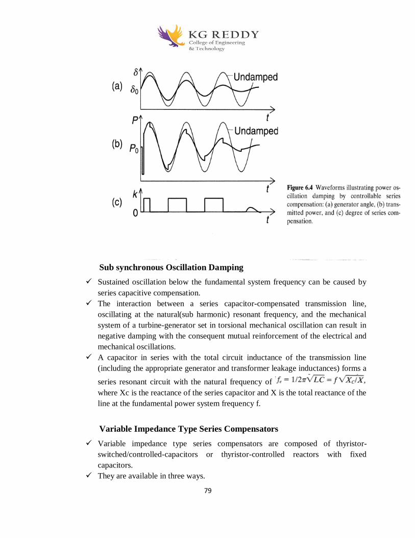
79
Sub synchronous Oscillation Damping
Sustained oscillation below the fundamental system frequency can be caused by
series capacitive compensation.
The interaction between a series capacitor-compensated transmission line,
oscillating at the natural(sub harmonic) resonant frequency, and the mechanical
system of a turbine-generator set in torsional mechanical oscillation can result in
negative damping with the consequent mutual reinforcement of the electrical and
mechanical oscillations.
A capacitor in series with the total circuit inductance of the transmission line
(including the appropriate generator and transformer leakage inductances) forms a
series resonant circuit with the natural frequency of
where Xc is the reactance of the series capacitor and X is the total reactance of the
line at the fundamental power system frequency f.
Variable Impedance Type Series Compensators
Variable impedance type series compensators are composed of thyristor-
switched/controlled-capacitors or thyristor-controlled reactors with fixed
capacitors.
They are available in three ways.
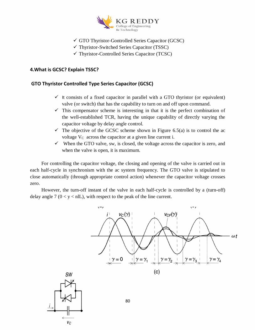
80
GTO Thyristor-Gontrolled Series Capacitor (GCSC)
Thyristor-Switched Series Capacitor (TSSC)
Thyristor-Controlled Series Capacitor (TCSC)
4.What is GCSC? Explain TSSC?
GTO Thyristor Controlled Type Series Capacitor (GCSC)
It consists of a fixed capacitor in parallel with a GTO thyristor (or equivalent)
valve (or switch) that has the capability to turn on and off upon command.
This compensator scheme is interesting in that it is the perfect combination of
the well-established TCR, having the unique capability of directly varying the
capacitor voltage by delay angle control.
The objective of the GCSC scheme shown in Figure 6.5(a) is to control the ac
voltage VC across the capacitor at a given line current i.
When the GTO valve, sw, is closed, the voltage across the capacitor is zero, and
when the valve is open, it is maximum.
For controlling the capacitor voltage, the closing and opening of the valve is carried out in
each half-cycle in synchronism with the ac system frequency. The GTO valve is stipulated to
close automatically (through appropriate control action) whenever the capacitor voltage crosses
zero.
However, the turn-off instant of the valve in each half-cycle is controlled by a (turn-off)
delay angle 7 (0 < y < nlL), with respect to the peak of the line current.

81
Thyristor Switched Series Capacitor (TSSC)
The basic circuit arrangement of the thyristor-switched series capacitor is shown
in Figure 6.10.
It consists of a number of capacitors, each shunted by an appropriately rated
bypass valve composed of a string of reverse parallel connected thyristors, in
series. As seen, it is similar to the circuit structure of the sequentially operated
GCSC shown in Figure 6.9, but its operation is different due to the imposed
switching restrictions of the conventional thyristor valve.
The operating principle of the TSSC is straightforward: the degree of series
compensation is controlled in a step-like manner by increasing or decreasing the
number of series capacitors inserted. A capacitor is inserted by turning off, and it
is bypassed by turning on the corresponding thyristor valve.
A thyristor valve commutates "naturally," that is, it turns off when the current
crosses zero. Thus a capacitor can be inserted into the line by the thyristor valve
only at the zero crossings of the line current.
Since the insertion takes place at line current zero,a full half-cycle of the line
current will charge the capacitor from zero to maximum and the successive,
opposite polarity half-cycle of the line current will discharge it from this
maximum to zeto, as illustrated in Figure 6.11.
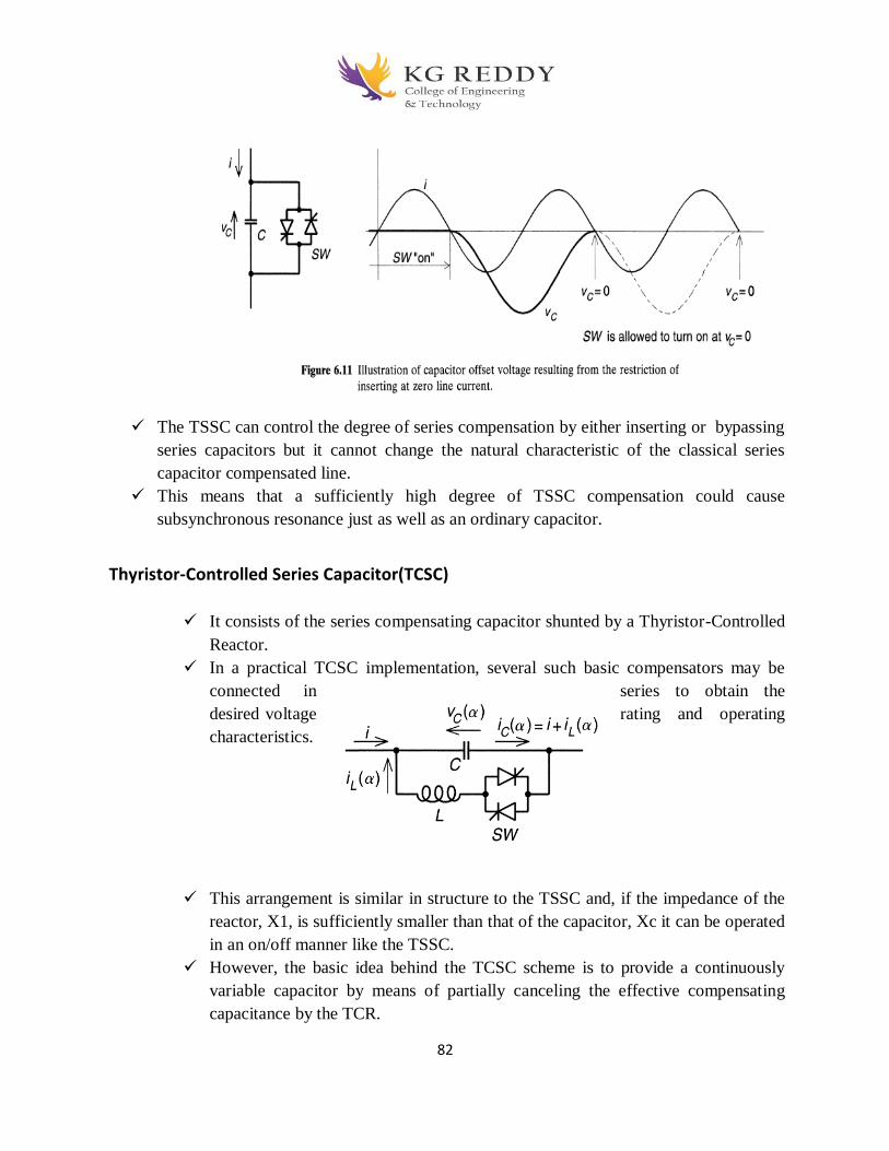
82
The TSSC can control the degree of series compensation by either inserting or bypassing
series capacitors but it cannot change the natural characteristic of the classical series
capacitor compensated line.
This means that a sufficiently high degree of TSSC compensation could cause
subsynchronous resonance just as well as an ordinary capacitor.
Thyristor-Controlled Series Capacitor(TCSC)
It consists of the series compensating capacitor shunted by a Thyristor-Controlled
Reactor.
In a practical TCSC implementation, several such basic compensators may be
connected in series to obtain the
desired voltage rating and operating
characteristics.
This arrangement is similar in structure to the TSSC and, if the impedance of the
reactor, X1, is sufficiently smaller than that of the capacitor, Xc it can be operated
in an on/off manner like the TSSC.
However, the basic idea behind the TCSC scheme is to provide a continuously
variable capacitor by means of partially canceling the effective compensating
capacitance by the TCR.

83
the TCR at the fundamental system frequency is a continuously variable reactive
impedance, controllable by delay angle a, the steady-state impedance of the TCSC
is that of a parallel LC circuit, consisting of a fixed capacitive impedance, Xc, and
a variable inductive impedance, XL(θ), that is,
The TCSC thus presents a tunable parallel LC circuit to the line current that is
substantially a constant alternating current source.
The TCSC has two operating ranges around its internal circuit resonance: one is
capacitive, and the other is inductive, as illustrated in above figure.
2. Explain the Basic Operating Control Schemes for GCSC, TSSC, and TCSC?
Operating Control Schemes for GCSC, TSSC, and TCSC
I. Functional Internal Control Scheme for the GCSC
This control scheme has four basic functions,
The first function is synchronous timing, provided by a phase-
locked loop circuit that runs in synchronism with the line current.
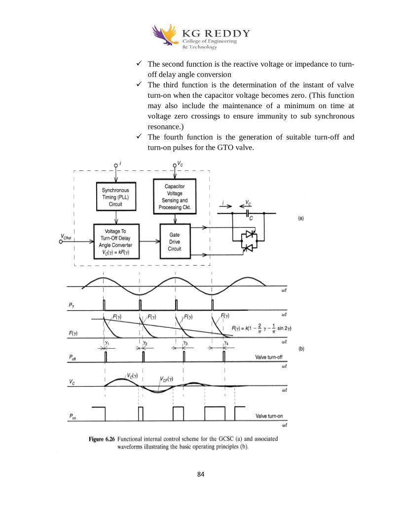
84
The second function is the reactive voltage or impedance to turn-
off delay angle conversion
The third function is the determination of the instant of valve
turn-on when the capacitor voltage becomes zero. (This function
may also include the maintenance of a minimum on time at
voltage zero crossings to ensure immunity to sub synchronous
resonance.)
The fourth function is the generation of suitable turn-off and
turn-on pulses for the GTO valve.
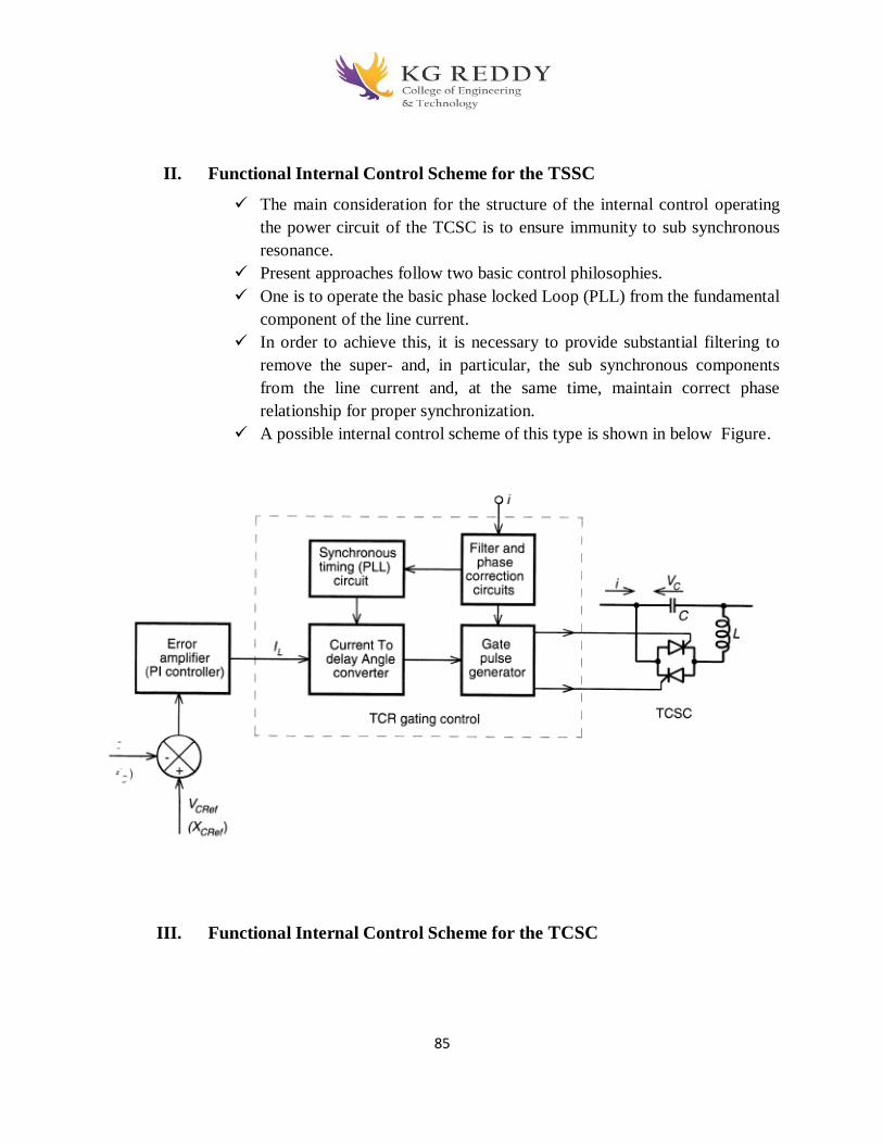
85
II. Functional Internal Control Scheme for the TSSC
The main consideration for the structure of the internal control operating
the power circuit of the TCSC is to ensure immunity to sub synchronous
resonance.
Present approaches follow two basic control philosophies.
One is to operate the basic phase locked Loop (PLL) from the fundamental
component of the line current.
In order to achieve this, it is necessary to provide substantial filtering to
remove the super- and, in particular, the sub synchronous components
from the line current and, at the same time, maintain correct phase
relationship for proper synchronization.
A possible internal control scheme of this type is shown in below Figure.
III. Functional Internal Control Scheme for the TCSC

86
This control approach also employs a PLL, synchronized to the line current, for the
generation of the basic timing reference.
However, in this method the actual zero crossing of the capacitor voltage is estimated
from the prevailing capacitor voltage and line current by an angle correction circuit.
The delay angle is then determine from the desired angle and the estimated correction
angle so as to make the TCR conduction symmetrical with respect to the expected zero
crossing.
Transmitted Power Versus Transmission Angle Characteristic
The SSSC injects the compensating voltage in series with the line irrespective of
the line current. The transmitted power Po versus the transmission angle
6relationship therefore becomes a parametric function of the injected voltage,
Vq(ζ), and it can be expressed for a two-machine system as follows:

87
The normalized power P versus angle δ plots as a parametric
function of Vq are shown in below Figure for Vq = 0, 0.353, and +-0.707.
For comparison, the normalized power P versus angle δ plots of a series capacitor
compensated two-machine system are shown in Figure 6.33 as a parametric
function of the degree of series compensation k For this comparison.
Comparison of the corresponding plots in Figures 6.32 and 6.33 clearly shows
that the series capacitor increases the transmitted power by a fixed percentage of
that transmitted by the uncompensated line at a given δ and, by contrast, the SSSC

88
can increase it by a fixed fraction of the maximum power transmittable by the
uncompensated line, independent of 6, in the important operating range of 0 < δ <
Φ/2.
89
Objective type Questions
1. Which type of slots are used in the construction of large size and small size induction motors
respectively?
a) open slots and semi closed slots
b) semi closed slots and open slots
c) open slots and open slots
d) semi closed slots and semi closed slots
2. In which of the following applications, wound rotor type of induction motor is used?
a) where the driven load requires speed control
b) where high starting torque is required
c) when external resistance is to be inserted
d) any of the mentioned
3. For an induction motor,
(i) squirrel cage type is simpler and more economical in construction
(ii) wound rotor type requires less maintenance
(iii) squirrel cage type is more rugged and requires less maintenance
(iv) no external resistance can be inserted in the rotor circuit of squirrel cage induction motor
(v) no external resistance can be inserted in the rotor circuit of a wound rotor induction motor
Which of the above statements are correct?
a) (ii),(v),(iii)
b) (ii),(iii),(v)
c) (i),(iii),(iv)
d) (i),(ii),(iv)
4. What are the advantages of providing the field winding on rotor and armature winding on the
stator?
a) more economical
b) more efficient
c) efficient cooling
d) all of the mentioned
5. The stator frame and end covers in synchronous and induction machines are designed to
___________
a) carry the magnetic flux
90
b) to serve as a mechanical support
c) to provide cooling or to carry induced EMF
d) any of the mentioned
6. What is the equation for frequency of generated EMF?
a) f = PN/120 Hz
b) f = 120/PN Hz
c) f = P/120 Hz
d) f = N/120 Hz
3. Voltage induce in the induction motor is highest at
a) starting
b) standstill
c) rated speed
d) any of the mentioned
8. The magnitude of various voltage drops that occur in an alternator, depends on
(A) power factor of the load
(B) load current
(C) power factor x load current
(D) power factor x (load current)2.
9. In an alternator, at lagging power factor, the generated voltage per phase, as compared to that
at unity power factor
(A) must be same as terminal voltage
(B) must be less than the terminal voltage
(C) must be more than the terminal voltage
(D) must be 1.41 time the terminal voltage.
10. The number of electrical degrees passed through in one revolution of a six pole synchronous
alternator is
(A) 360
(B) 720
(C) 1080
(D) 2160

91
Fill In The Blanks
1. Rotor resistance method can only be used with ______induction motor.
2. External methods like auto transformer are used to mainly ___________.
3. Core loss does not depend on the supply _________and __________.
4. Torque-slip characteristic of an induction motor is linear in the smaller slip values, because
effective rotor resistance is ___________ compared to _______.
5. For 3-phase induction motor, as load increases from no load towards the full load, torque
increases in proportion to _________.
6. As a 3-phase induction motor, as load increases from no load towards the full load,
_________________________.
7. A synchronous motor is used at ____________
8. To start the synchronous motor, it is first run as field excitation as zero, so we
_____________ them.
9. A poly phase synchronous motor will be used for the load of _____________ over poly
phase induction motor.
10. In an alternator, voltage drops occurs in_______________
Answers:
S.No MCQ Blanks
1 A NP/120
2 D Generator
3 C The prime mover torque, excitation
4 D Leading p.f.
5 B Field flux
6 A 60
7 C Low speed
8 B Short circuit
9 C 600 kW 500 rpm
10 C armature resistance, leakage reactance and armature reaction
92
UNIT-V
POWER FLOW CONTROLLERS
2-Marks Question and answers
1. What is TCSC?
TCSC is a capacitive reactance compensator, which consists of a series capacitor bank shunted
by a thyristor controlled reactor. The basic conceptual TCSC module comprises a series
capacitor, C,in parallel with a thyristor controlled reactor, Ls, in order to provide a smoothly
variable series capacitive reactance.
2. What is the basic principle of TCSC?
The basic operating principle behind the TCSC is that, it can provide a continuously variable
capacitor by means of partially cancelling the effective compensating capacitance of the
thyristor controlled reactor.
3. What are symptoms of voltage collapse?
The main symptoms of voltage collapse are low voltage profiles, heavy reactive power flows,
inadequate reactive support, and heavily loaded systems.
4. How is voltage instability identified in the power system?
Voltage instability problem is mainly because of insufficient reactive capacity of power
systems during disturbances like line outage contingencies. Voltage collapse is mathematically
indicated when the system Jacobian becomes singular.
5. What does voltage collapse means? How is system voltage stability limit improved?
Voltage collapse is a loss of stability in large scale electric power systems which causes
blackout when voltages decrease terribly. Voltage stability is primarily associated with the
reactive power support. FACTS devices can regulate the active and reactive power control as
well as adaptive to voltage magnitude control simultaneously because of their flexibility and
fast control characteristics. Placement of these devices in suitable location and proper
coordination between FACTS controllers can leads to control in line flow and maintain bus
voltages in desired level and so improve voltage stability margins and of the power systems.

93
3- Marks Question and answers
1. Explain the UPFC?
The Unified Power Flow Controller
The Unified Power Flow Controller (UPFC) concept was devised for the real-
time control and dynamic compensation of ac transmission systems, providing
multifunctional flexibility required to solve many of the problems facing the
power delivery industry.
Within the framework of traditional power transmission concepts, the UPFC is
able to control, simultaneously or selectively, all the parameters affecting
power flow in the transmission line (i.e., voltage, impedance, and phase angle),
and this unique capability is signified by the adjective "unified" in its name.
It can independently control both the real and reactive power flow in the line.
The reader should recall that, for all the Controllers discussed in the previous
chapters, the control of real power is associated with similar change in reactive
power, i.e., increased real power flow also resulted in increased reactive line
power.
.
i. What are the components of lighting system?
Head lamp, parking lamp, Stop light, rear lamp, reverse indicator roof light door lamp battery
ikindicator etc.
ii. What is the main purpose of dip switch?
Nowadays dazzling of light is more due to high intensity of light.If dazzling occurs, The light rays
will collapse. Together to form a layer. This can be avoided only with the help os dip switch
1. What is halogen head light bulb?
Halogen bulb has a higher light intensity than normal bulb and obtained by burning the incandescent
element at the higher temperature.
5. What is the use of oil pressure guage?
The gauges is used to show the pressure of oil used for lubricating purpose in the vehicle and these
gauges acts as awarning device against any likely damage to engine parts due to insufficient
lubricating oil.
2. What are the properties of electrical cable?

94
It should have least electric resistance .effective insulation through outlist olife, it should have high
flexibility.
3. What is the use ofo FUSES
They are use d for protecting the electrical equipments and circuits against the effects of excessive
current.
5Marks questions and answers 1. Explain the Basic Operating Principle of UPFC?
From the conceptual viewpoint, the UPFC is a generalized synchronous voltage
source (SVS), represented at the fundamental (power system) frequency by voltage
Phasor Vpq with controllable magnitude and angle ρ in series with the transmission
line, as illustrated for the usual elementary two machine system (or for two
independent systems with a transmission link intertie) in below Figure.
In this functionally unrestricted operation, which clearly includes voltage and angle
regulation, the SVS generally exchanges both reactive and real power with the
transmission system. Since, as established previously, an SVS is able to generate only
the reactive power exchanged, the real power must be supplied to it, or absorbed from
it, by a suitable power supply or sink.

95
In the UPFC arrangement the real power exchanged is provided by one of the end
buses (e.g., the sending-end bus), as indicated in above figure.
The UPFC consists of two voltage sourced converters, as illustrated in Figure 8.4.
These back-to-back converters, labeled "Converter 1" and "Converter 2" in the figure,
are operated from a common dc link provided by a dc storage capacitor.
As indicated before, this arrangement functions as an ideal ac-to-ac power converter
in which the real power can freely flow in either direction between the ac terminals of
the two converters, and each converter can independently generate (or absorb)
reactive power at its own ac output terminal.
Converter 2 provides the main function of the UPFC by injecting a voltage Vpq with
controllable magnitude Vpq and phase angle p in series with the line via an insertion
transformer. This injected voltage acts essentially as a synchronous ac voltage source.
The transmission line current flows through this voltage source resulting in reactive
and real power exchange between it and the ac system.
The basic function of Converter 1 is to supply or absorb the real power demanded by
Converter 2 at the common dc link to support the real power exchange resulting from
the series voltage injection.
This dc link power demand of Converter 2 is converted back to ac by Converter L and
coupled to the transmission line bus via a shunt connected transformer.
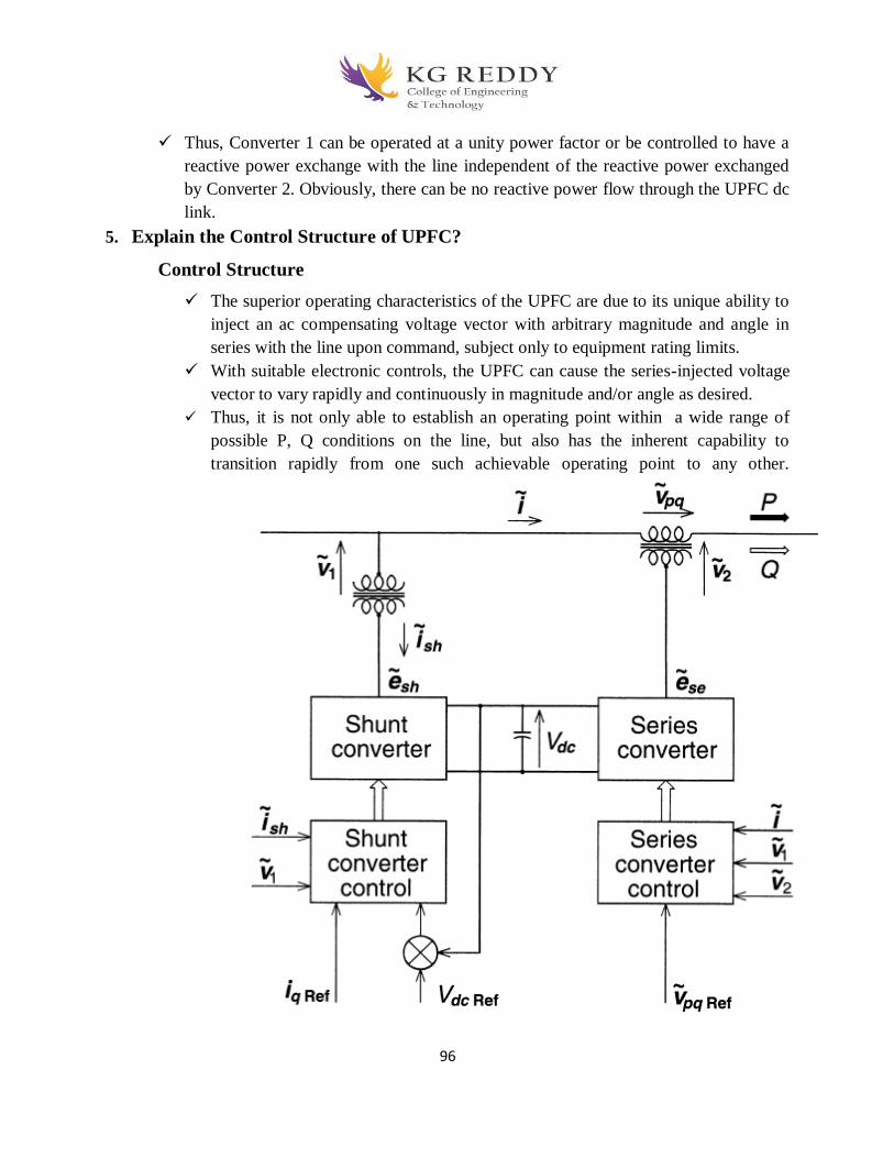
96
Thus, Converter 1 can be operated at a unity power factor or be controlled to have a
reactive power exchange with the line independent of the reactive power exchanged
by Converter 2. Obviously, there can be no reactive power flow through the UPFC dc
link.
5. Explain the Control Structure of UPFC?
Control Structure
The superior operating characteristics of the UPFC are due to its unique ability to
inject an ac compensating voltage vector with arbitrary magnitude and angle in
series with the line upon command, subject only to equipment rating limits.
With suitable electronic controls, the UPFC can cause the series-injected voltage
vector to vary rapidly and continuously in magnitude and/or angle as desired.
Thus, it is not only able to establish an operating point within a wide range of
possible P, Q conditions on the line, but also has the inherent capability to
transition rapidly from one such achievable operating point to any other.

97
The internal controls provide gating signals to the converter valves so that the
converter output voltages will properly respond to the internal reference variables,
IpRef, IqRef, and Vpq ref, in accordance with the basic control structure shown in
above Figure.
An overall control structure, showing the internal, the functional operation, and
system optimization controls with the internal and external references is presented
in below Figure.
the capability of unrestricted series voltage injection together with independently
controllable reactive power exchange offered by the circuit structure of two back-
to-back converters, facilitate several operating and control modes for the UPFC.

98
6. Explain the P and Q Control in FACTS?
This control mode utilizes most of the unique capabilities of the UPFC and it is
expected to be used as the basic mode in the majority of practical applications,
just as the shunt compensation is used normally for automatic voltage control.
Accordingly, block diagrams giving greater details of the control schemes are
show for the series converter in Figure 8.16(a) and for the shunt converter in
Figures 8.16(b) and (c) for operation in these modes.
The control scheme shown in Figure 8.16(a) assumes that the series converter can
generate output voltage with controllable magnitude and angle at a given dc bus
voltage.
As shown in Figure 8.16(a) the automatic power flow control for the series
converter is achieved by means of a vector control scheme that regulates the
transmission line current using a synchronous reference frame (established with
an appropriate phase locked loop producing reference angle 0) in which the
control quantities appear as dc signals in the steady state.

99
The control scheme for the shunt converter shown in Figure 8.16(b) also assumes
that the converter can generate output voltage with controllable magnitude and
angle.
7. Dynamic Performance
The dynamic performance of the UPFC is illustrated by real-time voltage and
current waveforms obtained in a representative TNA (Transient Network
Analyzer) hardware model shown schematically by a simplified single line
diagram in Figure 8.17.
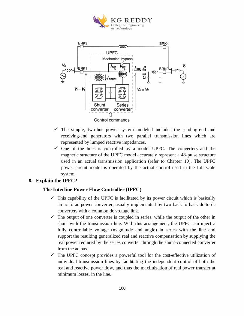
100
The simple, two-bus power system modeled includes the sending-end and
receiving-end generators with two parallel transmission lines which are
represented by lumped reactive impedances.
One of the lines is controlled by a model UPFC. The converters and the
magnetic structure of the UPFC model accurately represent a 48-pulse structure
used in an actual transmission application (refer to Chapter 10). The UPFC
power circuit model is operated by the actual control used in the full scale
system.
8. Explain the IPFC?
The Interline Power Flow Controller (IPFC)
This capability of the UPFC is facilitated by its power circuit which is basically
an ac-to-ac power converter, usually implemented by two back-to-back dc-to-dc
converters with a common dc voltage link.
The output of one converter is coupled in series, while the output of the other in
shunt with the transmission line. With this arrangement, the UPFC can inject a
fully controllable voltage (magnitude and angle) in series with the line and
support the resulting generalized real and reactive compensation by supplying the
real power required by the series converter through the shunt-connected converter
from the ac bus.
The UPFC concept provides a powerful tool for the cost-effective utilization of
individual transmission lines by facilitating the independent control of both the
real and reactive power flow, and thus the maximization of real power transfer at
minimum losses, in the line.

101
However, independent of their means of implementation, series reactive
compensators are unable to control the reactive power flow in, and thus the proper
load balancing of, the lines. This problem becomes particularly evident in those
cases where the ratio of reactive to resistive line impedance (X/R) is relatively
low.
The IPFC can potentially provide a highly effective scheme for power
transmission management at a multiline substation.
Basic Operating Principles and Characteristics
In its general form the Interline Power Flow Controller employs a number of dc-
to-ac converters each providing series compensation for a different line. In other
words, the IPFC comprises a number of Static Synchronous Series Compensators.
However, within the general concept of the IPFC, the compensating converters are
linked together at their dc terminals, as illustrated in below Figure.
With this scheme, in addition to providing series reactive compensation, any
converter can be controlled to supply real power to the common dc link from its
own transmission line.
Thus, an overall surplus power can be made available from the under utilized
lines which then can be used by other lines for real power compensation.
In this way, some of the converters, compensating overloaded lines or lines with a
heavy burden of reactive power flow, can be equipped with full two-dimensional,
reactive and real power control capability, similar to that offered by the UPFC.
102
The IPFC is particularly advantageous when controlled series compensation or
other series power flow control (e.g., phase shifting) is contemplated' this is
because the IPFC simply combines the otherwise independent series
compensators (SSSCs), without any significant hardware addition, and affords
some of those a greatly enhanced functional capability. The increase functional
capability can be moved from one line to another, as system conditions may
dictate. In addition, the individual converters of the IPF can be decoupled and
operated as independent series reactive compensators without any hardware
change.
Although converters with different dc voltage could be coupled via appropriate
d"-to-d" converters ("choppers"), the arrangement would be expensive with
relatively high operating losses. Therefore, it is desirable to establish a common
dc operating voltage for all converter-based Controllers used at one location,
which would facilitate their dc coupling and thereby an inexpensive extension of
their functional capabilities. Reasonably defined common dc operating voltage
should not impose significant restriction on the converter’ design, since at high
output power multiple parallel poles are normally employed. Apart from the
potential for dc coupling, common operating voltage would also be helpful for the
standardization of the converter type equipment used at one location, as well as
for the maintenance of spare Parts inventory.
The operating regions of the individual converters of the IPFC can differ
significantly, depending on the voltage and power ratings of the individual lines
and on the amount of compensation desired. It is evident that a high voltage/high-
power line may supply the necessary real power for a low voltage/ low-power
capacity line to optimize its power transmission, without significantly affecting its
own transmission.
The IPFC is an ideal solution to balance both the real and reactive power
flow in multiline and meshed systems.
The prime converters of the IPFC can be controlled to provide totally different operating
functions, e.g., independent (P) and (e) control, phase shifting (transmission angle regulation),
transmission impedance control, etc. These functions can be selected according to prevailing
system operating requirements

103
Objective Type Questions
1. Which among these is a method of wiring?
a. Joint box
b. Tee system
c. Loop in system
d. All of these
2. Which material is used for wiring continuous bus bar?
a. Aluminium
b. Copper
c. Both (A) and (B)
d. None of these
3. Which type of earthing is also called as ‘fire earthing’?
a. Plate earthing
b. Rod earthing
c. Strip earthing
d. All of these
4. What is the dimension of the copper strips used for the strip earthing?
a. 25 mm * 4 mm
b. 25 mm * 3 mm
c. 30 mm * 4 mm
d. 30 mm * 3 mm
5. What type of earthing is used by transmission lines?
a. Plate earthing
b. Rod earthing
c. Strip earthing
d. Both (a) & (c)
6. The leakage current must not be more than ____________ of maximum supply current
a. 1 / 1000
b. 1 / 100
c. 1 / 5000
d. 1 / 500

104
7. Which type of cable does not require bedding?
a. Paper insulated lead covered cables
b. PVC cables
c. Both (A) and (B)
d. None of these
8. In a circuit breaker the contact space is ionised by what?
a. Field emission from the contact surface.
b. Thermal emission from the contact surface.
c. Thermal ionisation of gas.
d. All of above
9. What is the relation between the fusing current and the diameter of the wire?
a. I = k d3
b. I = k d3/2
c. I = k d2
d. I = k d2/3
10.Circuit breakers usually operate under
a. Steady short circuit current
b. Sub transient state of short circuit current
c. Transient state of short circuit current
d. None of these
Fill In the Blanks
1. ___________________circuit breaker is preferred to be installed in extra high voltage AC
system?
2. ____________ is the main advantage of using a fuse?
3. An electrolyte cell consists of a _______and a ________electrode separated from each other
by an electrolyte.
4. The electrolyte can be concentrated aqueous solutions like ____________conductors like
organic salt solutions, polymers, ceramics etc.
5. Two or more such cells connected together in series or in a series-parallel array forms an
assembly called ____________

105
6. Charging current should be 10% of the Ah (Ampere hour) rating of battery.
Therefore, Charging current for 120Ah battery would be = 200Ah x (10/100) = _____
7. Standard open circuit voltage for Lead-acid battery at standard conditions is——-
8. Nickel-Cadmium batteries are preferred more than Lead-Acid batteries in military
applications because——–
9. MCB Stands for ____________
10. FDB stands for _____________
Answers:
S. No MCQ Blanks
1 D SF6 circuit breaker
2 A Current limiting effect under short circuit conditions
3 B Positive and Negative
4 A acids, alkalis or salts, or ionic
5 C Battery
6 B 20A
7 B 2.048 Volts
8 C Delivers large amount of power
9 B Miniature Circuit Breaker
10 B Fuse Distribution Board

106
17. Topics beyond syllabus with material


![INDEX [kgr.ac.in]kgr.ac.in/beta/wp-content/uploads/2018/09/DWDM_lab_manual_Final.pdf · DATAWARE HOUSING AND DATA MINIG LAB 1 COMPUTER SCIENCE & ENGINEERING INDEX S.NO EXPIREMENT](https://img.pdfslide.net/doc/110x75/5e169e90f0c32c7abc4e0d1a/index-kgracinkgracinbetawp-contentuploads201809dwdmlabmanualfinalpdf.jpg)


![Controller Design of STATCOM for Power System … · than SVC [6, 7]. The STATCOM is based on the principle that a voltage source inverter generates ... differences between HBMO algorithm](https://img.pdfslide.net/doc/110x75/5b5db8887f8b9ac6028ef856/controller-design-of-statcom-for-power-system-than-svc-6-7-the-statcom-is.jpg)


![INDEX [kgr.ac.in]kgr.ac.in › beta › wp-content › uploads › 2018 › 09 › SE_Lab_manual_Fi… · software engineering lab computer1 science & engineering index s.no name](https://img.pdfslide.net/doc/110x75/5f23933594199e2f1d12f9d7/index-kgracinkgracin-a-beta-a-wp-content-a-uploads-a-2018-a-09-a.jpg)