Embed Size (px)
Citation preview
Course Notes on
Entity-Relationship Data Model
Entity-Relationship Data Model
• Classical, popular conceptual data model
• First introduced (mid 70’s) as a (relatively minor) improvement to the relationalmodel: pictorial diagrams are easier to read than relational database schemas
• Then evolved as a popular model for the first conceptual representation of datastructures in the process of database design
• Today:
3 no ER standard, large variety of notations and concepts
3 simple versions in popular models, tools, and languages
3 richer versions in “semantic” data modeling
3 basis for the structural model of modern OO development methods
1
• Vocabulary:
3 “entity-relationship” is often translated as “entite-association” in French
3 English has “relation” and “relationship”
3 French only has “relation”
3 Spanish only has “relacion”
3 Brasilian Portuguese has “relacao” and “relacionamento”, but mostly uses “rela-tionship” :-)
Entity-Relationship Model, September 22, 2008 – 1
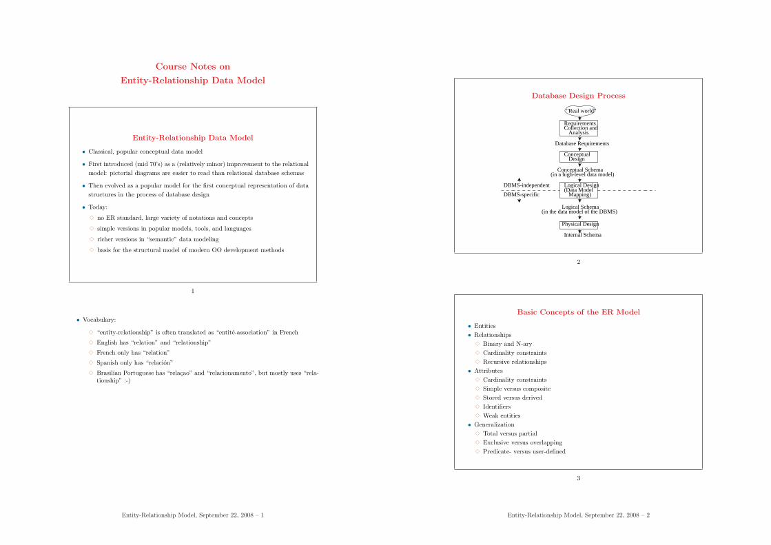
Database Design Process
"Real world"
ConceptualDesign
Conceptual Schema(in a high-level data model)
Mapping)
Logical Design(Data Model
(in the data model of the DBMS)Logical Schema
Physical Design
Internal Schema
Requirements
Analysis
Database Requirements
Collection and
DBMS-independent
DBMS-specific
2
Basic Concepts of the ER Model
• Entities• Relationships
3 Binary and N-ary3 Cardinality constraints3 Recursive relationships
• Attributes3 Cardinality constraints3 Simple versus composite3 Stored versus derived3 Identifiers3 Weak entities
• Generalization3 Total versus partial3 Exclusive versus overlapping3 Predicate- versus user-defined
3
Entity-Relationship Model, September 22, 2008 – 2
Entities and Entity Classes
• Entity:
3 important individual thing, object, concept in the real world of interest (e.g.,the person called John, my red car, . . .)
3 physical (e.g., persons, cars, . . .) or conceptual (e.g., companies, jobs, . . .)
• Entity class:
3 concept, type, common prototype (intension), set of potential instances
3 current collection of instances (extension)
3 mechanism for creating instances (“object factory”, “cookie cutter”)
4
• Vocabulary:
3 the distinction bewteen type or class and their instances is classical in informatics(programming languages)
3 entity is often used for individuals (instance, occurrence), entity is also used forentity type, entity set and entity class
3 an important difference with the use of types in programming languages is thatdatabase management puts more emphasis on the extension of an entity class ina database, i.e., the current collection of instances of the entity type
3 in practice, for this chapter: “entity” ≈ “object”
Entity-Relationship Model, September 22, 2008 – 3
Grouping Entities into Classes
5
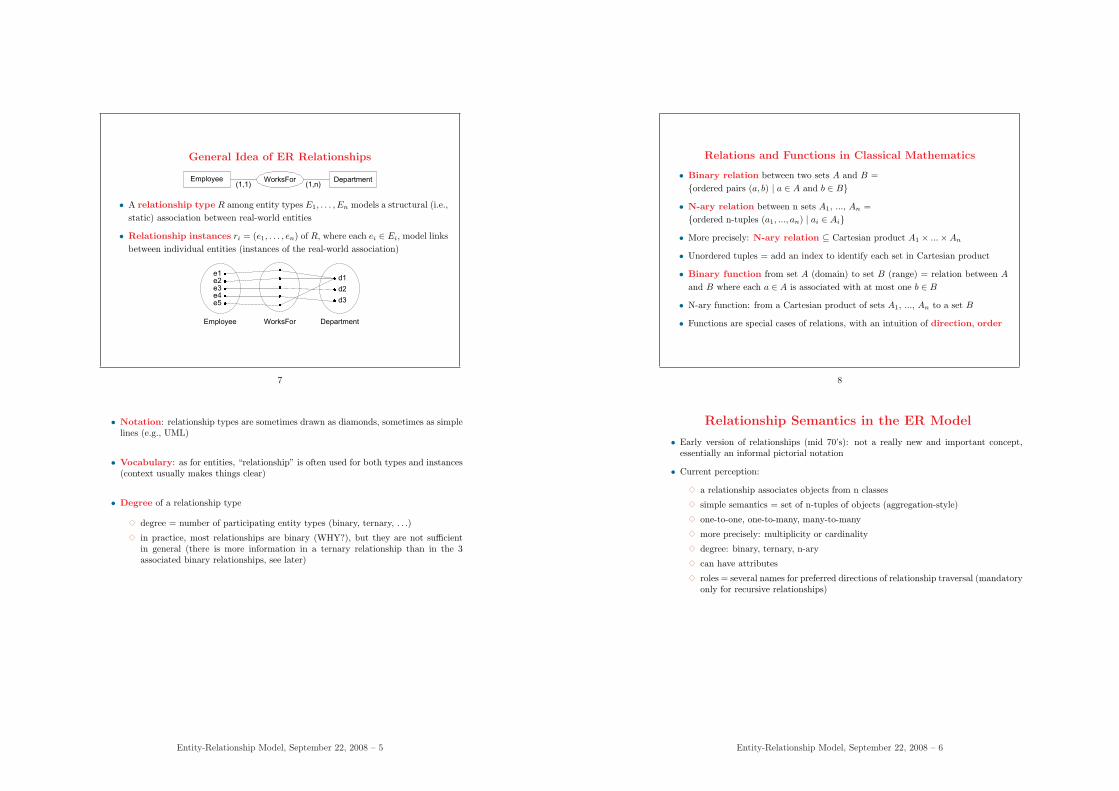
Class-Instance Relationship
• The relationship between a class or type and its instances is called instantiation/ classification
• A class defines a common template for its instances
• Intances have a value for each attribute defined in their class
Person
Name
BDate
Job
John
1/5/1975
Clerk
Peter
7/8/1980
Engineer
is-of
6
Entity-Relationship Model, September 22, 2008 – 4
General Idea of ER Relationships
Employee WorksFor(1,n)
Department(1,1)
• A relationship type R among entity types E1, . . . , En models a structural (i.e.,static) association between real-world entities
• Relationship instances ri = (e1, . . . , en) of R, where each ei ∈ Ei, model linksbetween individual entities (instances of the real-world association)
e1 e2 e3 e4 e5
d1
d2
d3
Employee WorksFor Department
7
• Notation: relationship types are sometimes drawn as diamonds, sometimes as simplelines (e.g., UML)
• Vocabulary: as for entities, “relationship” is often used for both types and instances(context usually makes things clear)
• Degree of a relationship type
3 degree = number of participating entity types (binary, ternary, . . .)
3 in practice, most relationships are binary (WHY?), but they are not sufficientin general (there is more information in a ternary relationship than in the 3associated binary relationships, see later)
Entity-Relationship Model, September 22, 2008 – 5
Relations and Functions in Classical Mathematics
• Binary relation between two sets A and B ={ordered pairs (a, b) | a ∈ A and b ∈ B}
• N-ary relation between n sets A1, ..., An ={ordered n-tuples (a1, ..., an) | ai ∈ Ai}
• More precisely: N-ary relation ⊆ Cartesian product A1 × ...×An
• Unordered tuples = add an index to identify each set in Cartesian product
• Binary function from set A (domain) to set B (range) = relation between A
and B where each a ∈ A is associated with at most one b ∈ B
• N-ary function: from a Cartesian product of sets A1, ..., An to a set B
• Functions are special cases of relations, with an intuition of direction, order
8
Relationship Semantics in the ER Model
• Early version of relationships (mid 70’s): not a really new and important concept,essentially an informal pictorial notation
• Current perception:
3 a relationship associates objects from n classes
3 simple semantics = set of n-tuples of objects (aggregation-style)
3 one-to-one, one-to-many, many-to-many
3 more precisely: multiplicity or cardinality
3 degree: binary, ternary, n-ary
3 can have attributes
3 roles = several names for preferred directions of relationship traversal (mandatoryonly for recursive relationships)
Entity-Relationship Model, September 22, 2008 – 6
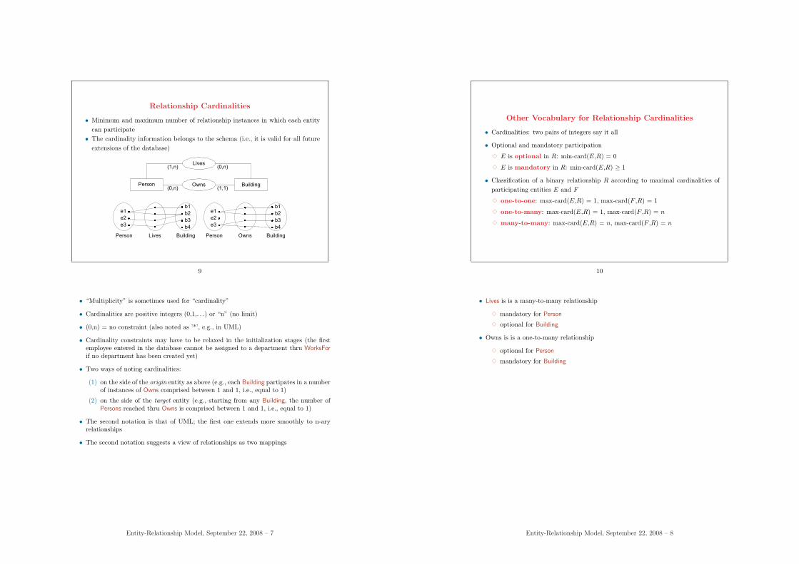
Relationship Cardinalities
• Minimum and maximum number of relationship instances in which each entitycan participate
• The cardinality information belongs to the schema (i.e., it is valid for all futureextensions of the database)
Person Owns(1,1)
Building(0,n)
Person Lives Building
b1
b2
b3
b4
e1
e2
e3
Lives(0,n)(1,n)
Person Owns Building
b1
b2
b3
b4
e1
e2
e3
9
• “Multiplicity” is sometimes used for “cardinality”
• Cardinalities are positive integers (0,1,. . .) or “n” (no limit)
• (0,n) = no constraint (also noted as ’*’, e.g., in UML)
• Cardinality constraints may have to be relaxed in the initialization stages (the firstemployee entered in the database cannot be assigned to a department thru WorksForif no department has been created yet)
• Two ways of noting cardinalities:
(1) on the side of the origin entity as above (e.g., each Building partipates in a numberof instances of Owns comprised between 1 and 1, i.e., equal to 1)
(2) on the side of the target entity (e.g., starting from any Building, the number ofPersons reached thru Owns is comprised between 1 and 1, i.e., equal to 1)
• The second notation is that of UML; the first one extends more smoothly to n-aryrelationships
• The second notation suggests a view of relationships as two mappings
Entity-Relationship Model, September 22, 2008 – 7
Other Vocabulary for Relationship Cardinalities
• Cardinalities: two pairs of integers say it all
• Optional and mandatory participation
3 E is optional in R: min-card(E,R) = 0
3 E is mandatory in R: min-card(E,R) ≥ 1
• Classification of a binary relationship R according to maximal cardinalities ofparticipating entities E and F
3 one-to-one: max-card(E,R) = 1, max-card(F ,R) = 1
3 one-to-many: max-card(E,R) = 1, max-card(F ,R) = n
3 many-to-many: max-card(E,R) = n, max-card(F ,R) = n
10
• Lives is is a many-to-many relationship
3 mandatory for Person
3 optional for Building
• Owns is is a one-to-many relationship
3 optional for Person
3 mandatory for Building
Entity-Relationship Model, September 22, 2008 – 8
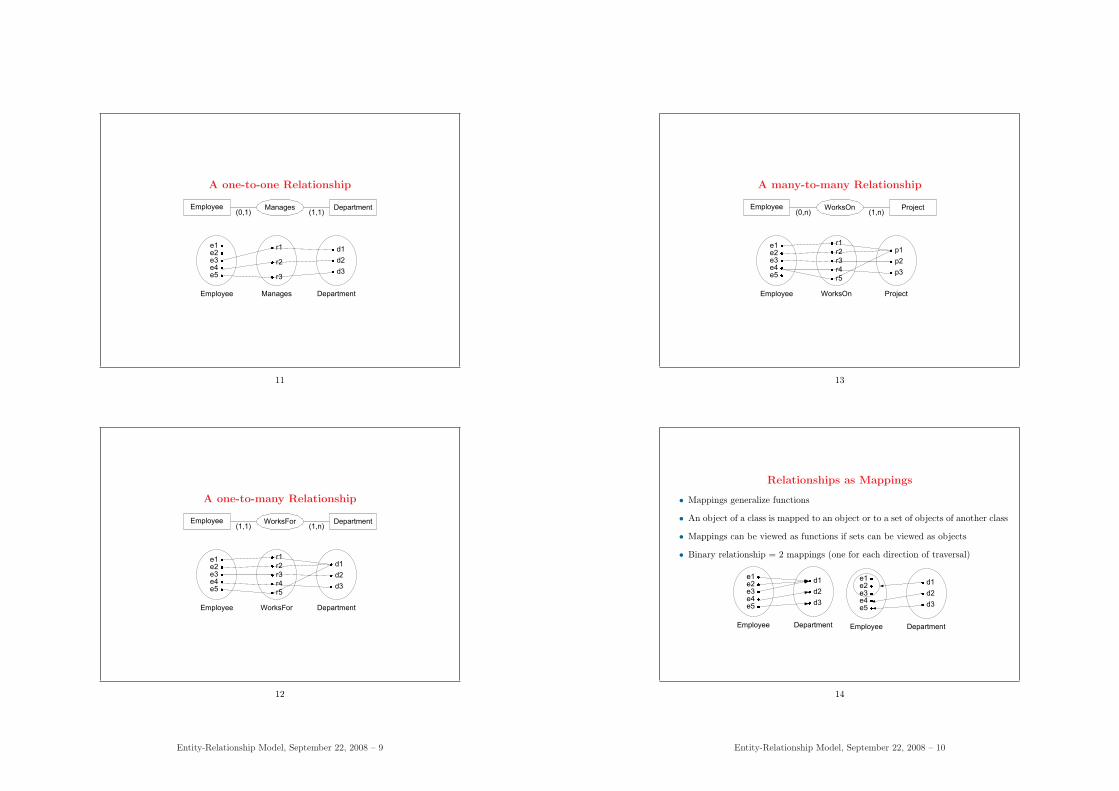
A one-to-one Relationship
Employee Manages(1,1)
Department(0,1)
e1 e2 e3 e4 e5
r1
r2
r3
Employee Manages Department
d1
d2
d3
11
A one-to-many Relationship
Employee WorksFor(1,n)
Department(1,1)
e1 e2 e3 e4 e5
r1
r2
r3
r4
r5
d1
d2
d3
Employee WorksFor Department
12
Entity-Relationship Model, September 22, 2008 – 9
A many-to-many Relationship
Employee WorksOn(1,n)
Project(0,n)
e1 e2 e3 e4 e5
r1
r2
r3
r4
r5
p1
p2
p3
Employee WorksOn Project
13
Relationships as Mappings
• Mappings generalize functions
• An object of a class is mapped to an object or to a set of objects of another class
• Mappings can be viewed as functions if sets can be viewed as objects
• Binary relationship = 2 mappings (one for each direction of traversal)
Employee Department
d1
d2
d3
e1 e2 e3 e4 e5
Employee Department
d1
d2
d3
e1 e2 e3 e4 e5
14
Entity-Relationship Model, September 22, 2008 – 10
• Bidirectional or “oriented” relationships?
3 mathematical relations are not oriented (binary relations are inherently bidirec-tional)
3 most versions of the entity-relationship model treat relationships as not oriented;some versions view them as directed
3 asymmetry comes from
∗ linguistics: relationship names rarely correspond to traversal in both direc-tions
∗ implementation techniques: a traditional implementation of relationships isas pointers from one entity to related entities
∗ implementation efficiency: one direction of traversal may be more efficientlyimplemented (but this violates data independence)
∗ application needs: it may be justified to privilege one direction of traversal
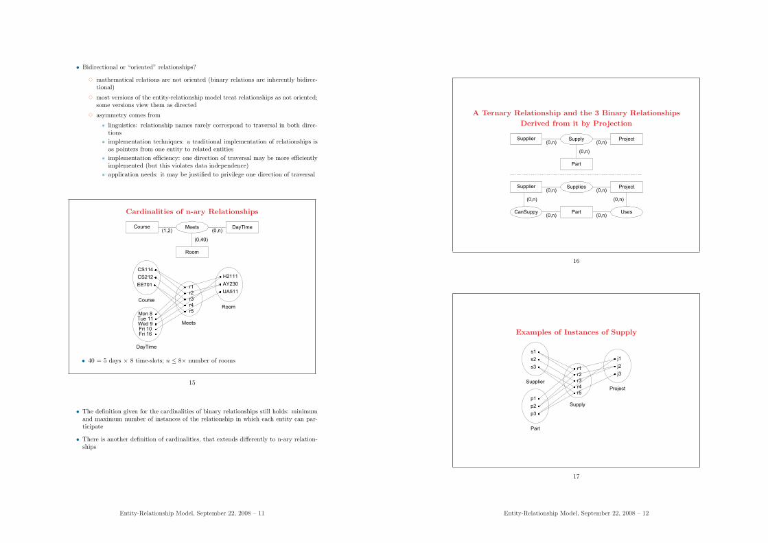
Cardinalities of n-ary Relationships
Course Meets(0,n)
DayTime(1,2)
DayTime
Meets
Room
H2111
AY230
UA511
Mon 8Tue 11Wed 9Fri 10Fri 16
r1
r2
r3
r4
r5
Room
(0,40)
Course
CS114
CS212
EE701
• 40 = 5 days × 8 time-slots; n ≤ 8× number of rooms
15
• The definition given for the cardinalities of binary relationships still holds: minimumand maximum number of instances of the relationship in which each entity can par-ticipate
• There is another definition of cardinalities, that extends differently to n-ary relation-ships
Entity-Relationship Model, September 22, 2008 – 11
A Ternary Relationship and the 3 Binary Relationships
Derived from it by Projection
Supplier Supply(0,n)
Project(0,n)
Part
(0,n)
Supplier Supplies(0,n)
Project(0,n)
Part UsesCanSuppy(0,n) (0,n)
(0,n)(0,n)
16
Examples of Instances of Supply
p1
p2
p3
r1
r2
r3
r4
r5
j1
j2
j3
Part
Supply
Project
s1
s2
s3
Supplier
17
Entity-Relationship Model, September 22, 2008 – 12
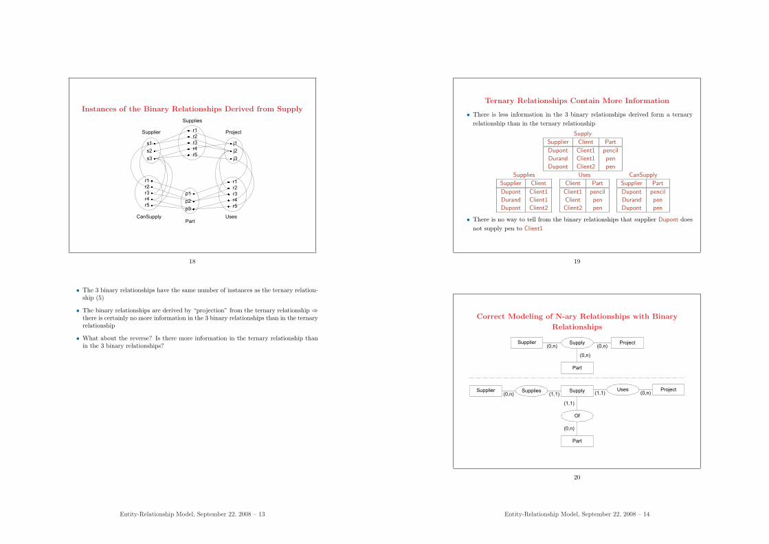
Instances of the Binary Relationships Derived from Supply
r1
r2
r3
r4
r5
Part
Supplies
s1
s2
s3
Supplier
r1
r2
r3
r4
r5
r1
r2
r3
r4
r5
j1
j2
j3
p1
p2
p3
Project
UsesCanSupply
18
• The 3 binary relationships have the same number of instances as the ternary relation-ship (5)
• The binary relationships are derived by “projection” from the ternary relationship ⇒there is certainly no more information in the 3 binary relationships than in the ternaryrelationship
• What about the reverse? Is there more information in the ternary relationship thanin the 3 binary relationships?
Entity-Relationship Model, September 22, 2008 – 13
Ternary Relationships Contain More Information
• There is less information in the 3 binary relationships derived form a ternaryrelationship than in the ternary relationship
Supply
Supplier Client Part
Dupont Client1 pencil
Durand Client1 pen
Dupont Client2 pen
Supplies
Supplier Client
Dupont Client1
Durand Client1
Dupont Client2
Uses
Client Part
Client1 pencil
Client pen
Client2 pen
CanSupply
Supplier Part
Dupont pencil
Durand pen
Dupont pen
• There is no way to tell from the binary relationships that supplier Dupont doesnot supply pen to Client1
19
Correct Modeling of N-ary Relationships with Binary
Relationships
Supplier Supply(0,n)
Project(0,n)
Part
(0,n)
Supplier Supplies(1,1)
Supply(0,n)
Part
Of
(1,1)
Uses(0,n)
Project(1,1)
(0,n)
20
Entity-Relationship Model, September 22, 2008 – 14
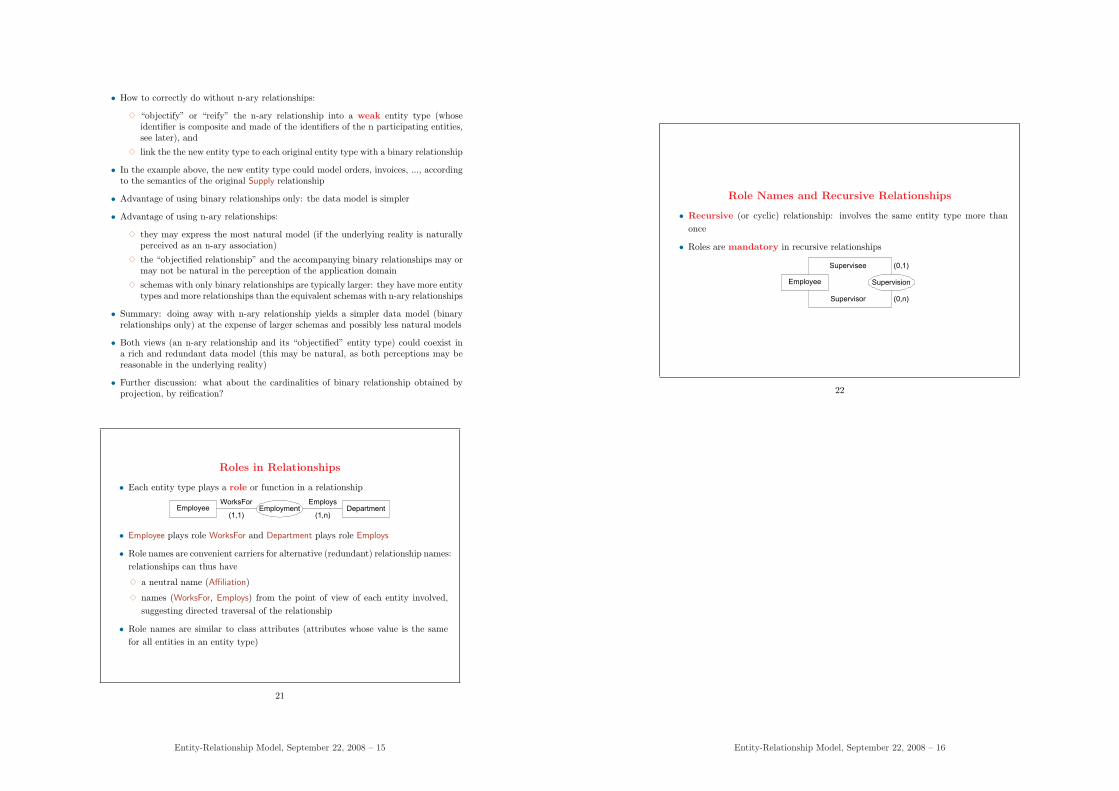
• How to correctly do without n-ary relationships:
3 “objectify” or “reify” the n-ary relationship into a weak entity type (whoseidentifier is composite and made of the identifiers of the n participating entities,see later), and
3 link the the new entity type to each original entity type with a binary relationship
• In the example above, the new entity type could model orders, invoices, ..., accordingto the semantics of the original Supply relationship
• Advantage of using binary relationships only: the data model is simpler
• Advantage of using n-ary relationships:
3 they may express the most natural model (if the underlying reality is naturallyperceived as an n-ary association)
3 the “objectified relationship” and the accompanying binary relationships may ormay not be natural in the perception of the application domain
3 schemas with only binary relationships are typically larger: they have more entitytypes and more relationships than the equivalent schemas with n-ary relationships
• Summary: doing away with n-ary relationship yields a simpler data model (binaryrelationships only) at the expense of larger schemas and possibly less natural models
• Both views (an n-ary relationship and its “objectified” entity type) could coexist ina rich and redundant data model (this may be natural, as both perceptions may bereasonable in the underlying reality)
• Further discussion: what about the cardinalities of binary relationship obtained byprojection, by reification?
Roles in Relationships
• Each entity type plays a role or function in a relationship
Employee Employment(1,n)
Department(1,1)
EmploysWorksFor
• Employee plays role WorksFor and Department plays role Employs
• Role names are convenient carriers for alternative (redundant) relationship names:relationships can thus have
3 a neutral name (Affiliation)
3 names (WorksFor, Employs) from the point of view of each entity involved,suggesting directed traversal of the relationship
• Role names are similar to class attributes (attributes whose value is the samefor all entities in an entity type)
21
Entity-Relationship Model, September 22, 2008 – 15
Role Names and Recursive Relationships
• Recursive (or cyclic) relationship: involves the same entity type more thanonce
• Roles are mandatory in recursive relationships
Employee Supervision
(0,1)
(0,n)
Supervisee
Supervisor
22
Entity-Relationship Model, September 22, 2008 – 16
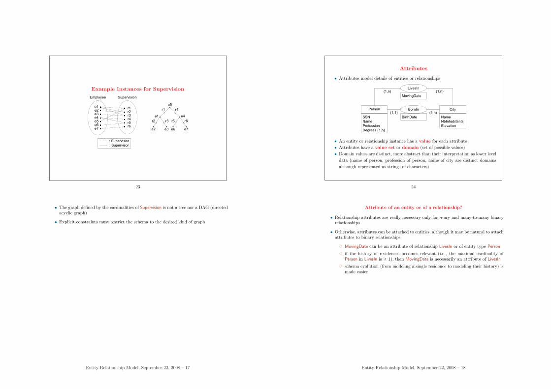
Example Instances for Supervision
e1 e2 e3 e4 e5 e6 e7
r1r2r3r4r5r6
Employee Supervision
e5
e1
e2 e3 e6 e7
e4
r1 r4
r2 r3 r5 r6
: Supervisee
: Supervisor
23
• The graph defined by the cardinalities of Supervision is not a tree nor a DAG (directedacyclic graph)
• Explicit constraints must restrict the schema to the desired kind of graph
Entity-Relationship Model, September 22, 2008 – 17
Attributes
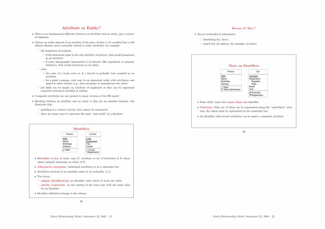
• Attributes model details of entities or relationships
Person BornIn(1,n)
City(1,1)
LivesIn(1,n)(1,n)
MovingDate
BirthDate Name
NbInhabitants
Elevation
SSN
Name
Profession
Degrees (1,n)
• An entity or relationship instance has a value for each attribute• Attributes have a value set or domain (set of possible values)• Domain values are distinct, more abstract than their interpretation as lower level
data (name of person, profession of person, name of city are distinct domainsalthough represented as strings of characters)
24
Attribute of an entity or of a relationship?
• Relationship attributes are really necessary only for n-ary and many-to-many binaryrelationships
• Otherwise, attributes can be attached to entities, although it may be natural to attachattributes to binary relationships
3 MovingDate can be an attribute of relationship LivesIn or of entity type Person
3 if the history of residences becomes relevant (i.e., the maximal cardinality ofPerson in LivesIn is ≥ 1), then MovingDate is necessarily an attribute of LivesIn
3 schema evolution (from modeling a single residence to modeling their history) ismade easier
Entity-Relationship Model, September 22, 2008 – 18

Attribute Cardinalities
• Like relationships, attributes have minimal and maximal cardinalities
• Optional ⇔ Mandatory
3 mandatory: min-card ≥ 1
3 optional: min-card = 0
• Several possible meanings for “null values”:
3 not applicable: (a person does not have a university degree)
3 unknown but known to exist: (phone number exists, unknown to thedatabase)
3 unknown, not known to exist: (phone number may exist)
• Single-valued ⇔ Multivalued
3 single-valued: max-card = 1 (one value for each entity, e.g., Age)
3 multivalued: max-card > 1 (a set of values for each entity, e.g. Degrees)
25
• Notations
3 the most frequent case of attribute cardinality is (1,1), i.e., mandatory monoval-ued attributes; this is often taken as the default notation (i.e., when no cardinalityis indicated explicitly, then (1,1) is meant)
3 the cardinality (0,n) for optional multivalued attributes is sometimes noted as a∗ (e.g., attribute Degree of Person)
Entity-Relationship Model, September 22, 2008 – 19
Derived Attributes
• Two or more attributes can be related
Person
SSN
Name
BirthDate
/Age
• The value of Age may be determined from the current date and the BirthDate:Age is a derived attribute
• The constraint must be noted in the schema (and the redundancy properly man-aged)
• How derived attributes are implemented is another issue
26
Composite Attributes
Person
SSN
Name
Address
Street
City
State
ZipCode
Country
• Composite attribute: formed by aggregating related attributes
• Nondivisible attributes are called simple or atomic
• Composite attribute:
3 its value is a tuple of values for its constituent simple attributes
3 introduces a third level of structure (entity, composite attribute, simple at-tribute)
3 represents groups of values that go together but are not thought importantenough to make up an entity
27
Entity-Relationship Model, September 22, 2008 – 20
Attribute or Entity?
• There is no fundamental difference between an attribute and an entity, just a matterof emphasis
• Choose an entity instead of an attribute if the piece of data to be modeled has a welldefined identity and is naturally related to other attributes, for example:
3 the hometown of students
∗ if the hometown name is the only attribute of interest, then model hometownas an attribute
∗ if some demographic information is of interest (like population or primaryindustry), then model hometown as an entity
3 color
∗ the color of a book cover or of a bicycle is probably best modeled as anattribute
∗ for a paint company, color may be an important entity with attributes, andlinked to other entities (e.g., dyes necessary to manufacture the color)
3 job skills can be simply an attribute of employees or they can be importantcorporate ressources modeled as entities
• Composite attributes are not present in many versions of the ER model
• Deciding between an attribute and an entity is thus not an absolute decision; thisillustrates that
3 modeling is a creative activity that cannot be automated
3 there are many ways to represent the same “real world” in a database
Identifiers
Person
SSN
Name
BirthDate
Address
Course
Code
Department
Title
Credits
SSN (Code, Department)
• Identifier or key of entity type E: attribute or set of attributes of E whosevalues uniquely determine an entity of E
• Alternative notations: underlined attributes or in a constraint box
• Attributes involved in an identifier must be of cardinality (1,1)
• Two facets
3 unique identification: an identifier value selects at most one entity
3 unicity constraint: no two entities of the same type with the same valuefor an identifier
• Identifier definition belongs to the schema
28
Entity-Relationship Model, September 22, 2008 – 21
Beware of “Key”!
• Key is overloaded in informatics:
3 identifying key (here)
3 search key (in indexes, for example, see later)
More on Identifiers
Person
SSN
Name
BirthDate
Address
SSN(Name,BirthDate)
Car
VehicleId
Registration
RegistNo
State
Model
Year
VehicleId
Registration
• Some entity types have more than one identifier
• Notation: Only one of them can be represented using the “underlined” nota-tion, the others must be represented in the constraint box
• An identifier with several attributes can be made a composite attribute
29
Entity-Relationship Model, September 22, 2008 – 22
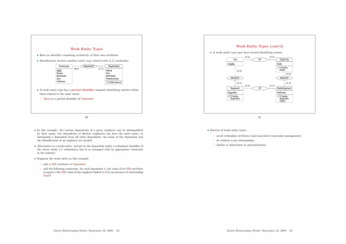
Weak Entity Types
• Have no identifier consisting exclusively of their own attributes
• Identification involves another entity type related with (1,1) cardinality
Employee
SSN
Name
BirthDate
Sex
Address
Name
Sex
BirthDate
Relationship
DependOf(1,1)
Dependent(0,n)
(SSN,Name)
• A weak entity type has a partial identifier uniquely identifying entities withinthose related to the same owner
3 Name is a partial identifier of Dependent
30
• In this example, the various dependents of a given employee can be distinguishedby their name, but dependents of distinct employees can have the same name; todistinguish a dependent from all other dependents, the name of the dependent andthe identification of an employee are needed
• Alternative to a weak entity: include in the dependent entity a redundant identifier ofthe owner entity (⇒ redundancy has to ne managed with an appropriate constraintin the schema)
• Suppress the weak entity in this example:
3 add a SSN attribute to Dependent
3 add the following constraint: for each dependent d, the value of its SSN attributeis equal to the SSN value of the employee linked to d by an instance of relationshipDepOf
Entity-Relationship Model, September 22, 2008 – 23
Weak Entity Types (cont’d)
• A weak entity type may have several identifying owners
Trip
TripNo Date
Of(1,1)
DailyTrip(1,n)
Segment
SegmNo
Of(1,1)
DailySegment(1,n)
MadeOf MadeOf
(1,n)
(1,1) (1,1)
(1,n)
NbSeats
(TripNo, SegmNo)
(TripNo, SegmNo, Date)
(TripNo, Date)
31
• Interest of weak entity types:
3 avoid redundant attributes (and associated constraint management)
3 do without n-ary relationships
3 similar to inheritance in generalizations
Entity-Relationship Model, September 22, 2008 – 24
Generic Relationships
• Generic relationships = templates to be specialized for relating classes
3 generalization: Superclass ← Subclass
3 classification: Class<- - -Instance
3 aggregation: Whole¦—Part
3 materialization: Abstract—∗Concrete
• Generic relationships abstract specific relationships: they can be viewed asmetarelationships
3 they are part of the language for defining ER schemas (specific relationshipsare part of schemas)
3 a specific relationship (e.g., Person ← Employee is an instance of the corre-sponding generic relationship
32
Generalization
Person
Car Bus TruckStudent Employee
Vehicle
SSN
Name
SalaryDepartment
SerialNo
Owner
#Doors #Axles#Seats
• Special relationship between several subentities (subclasses) and a higher-level, more abstract superentity (superclass)
• Specialization: the relationship viewed from the superclass
• Two aspects
3 inheritance: built-in mechanism
3 is-a relationship: relationship with specific semantics;substitution principle: instances of subclasses can also be viewed as in-stances of their superclasses
33
Entity-Relationship Model, September 22, 2008 – 25
Generalization: Inheritance
34
Intuitive definition of inheritance
• built-in object-oriented and ER mechanism
• whose effect is as if all properties of the superclass had also been defined for allsubclasses
Entity-Relationship Model, September 22, 2008 – 26
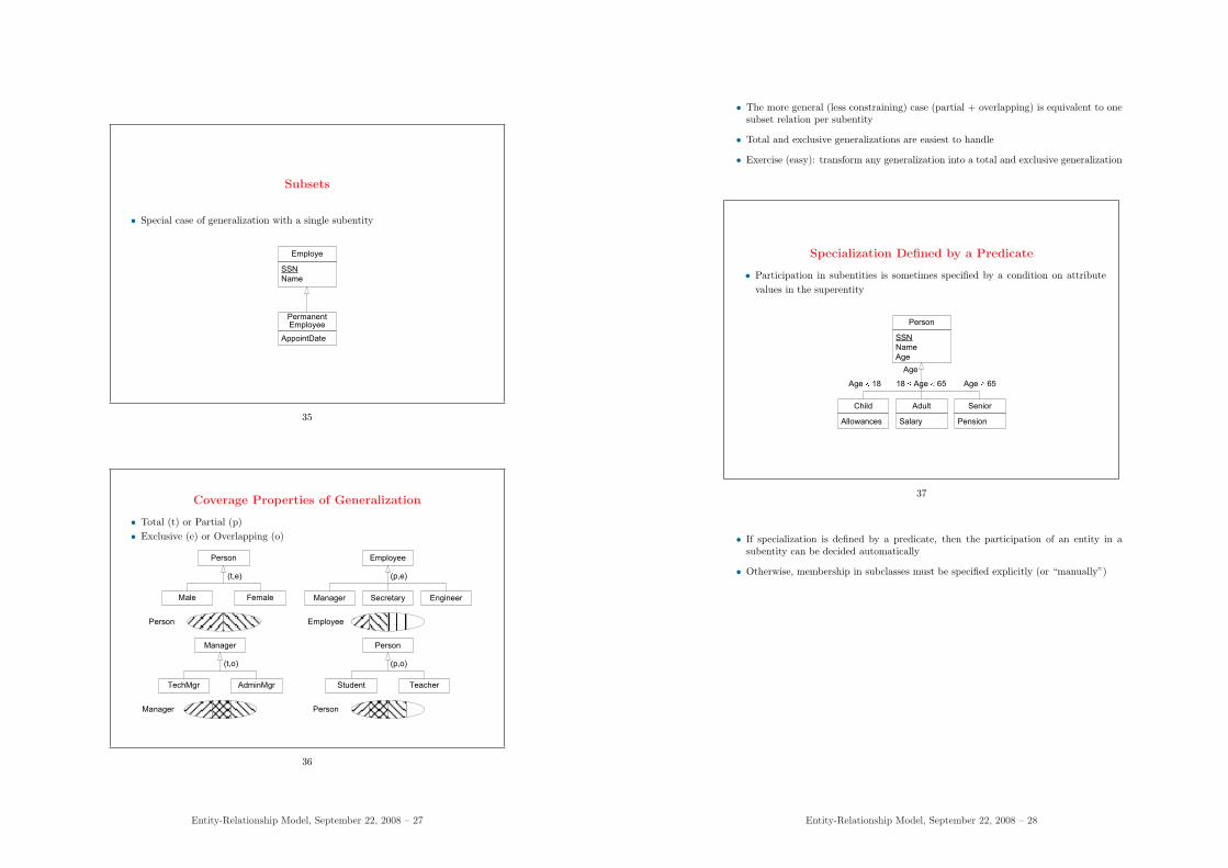
Subsets
• Special case of generalization with a single subentity
Employe
PermanentEmployee
SSN
Name
AppointDate
35
Coverage Properties of Generalization
• Total (t) or Partial (p)• Exclusive (e) or Overlapping (o)
Person
Manager Secretary EngineerMale Female
Employee
Manager
TechMgr AdminMgr
Person
Student Teacher
(t,e) (p,e)
(t,o) (p,o)
EmployeePerson
Manager Person
36
Entity-Relationship Model, September 22, 2008 – 27
• The more general (less constraining) case (partial + overlapping) is equivalent to onesubset relation per subentity
• Total and exclusive generalizations are easiest to handle
• Exercise (easy): transform any generalization into a total and exclusive generalization
Specialization Defined by a Predicate
• Participation in subentities is sometimes specified by a condition on attributevalues in the superentity
Person
Child Adult Senior
SSN
Name
Age
Allowances PensionSalary
Age
Age 18 18 Age 65 Age 65
37
• If specialization is defined by a predicate, then the participation of an entity in asubentity can be decided automatically
• Otherwise, membership in subclasses must be specified explicitly (or “manually”)
Entity-Relationship Model, September 22, 2008 – 28
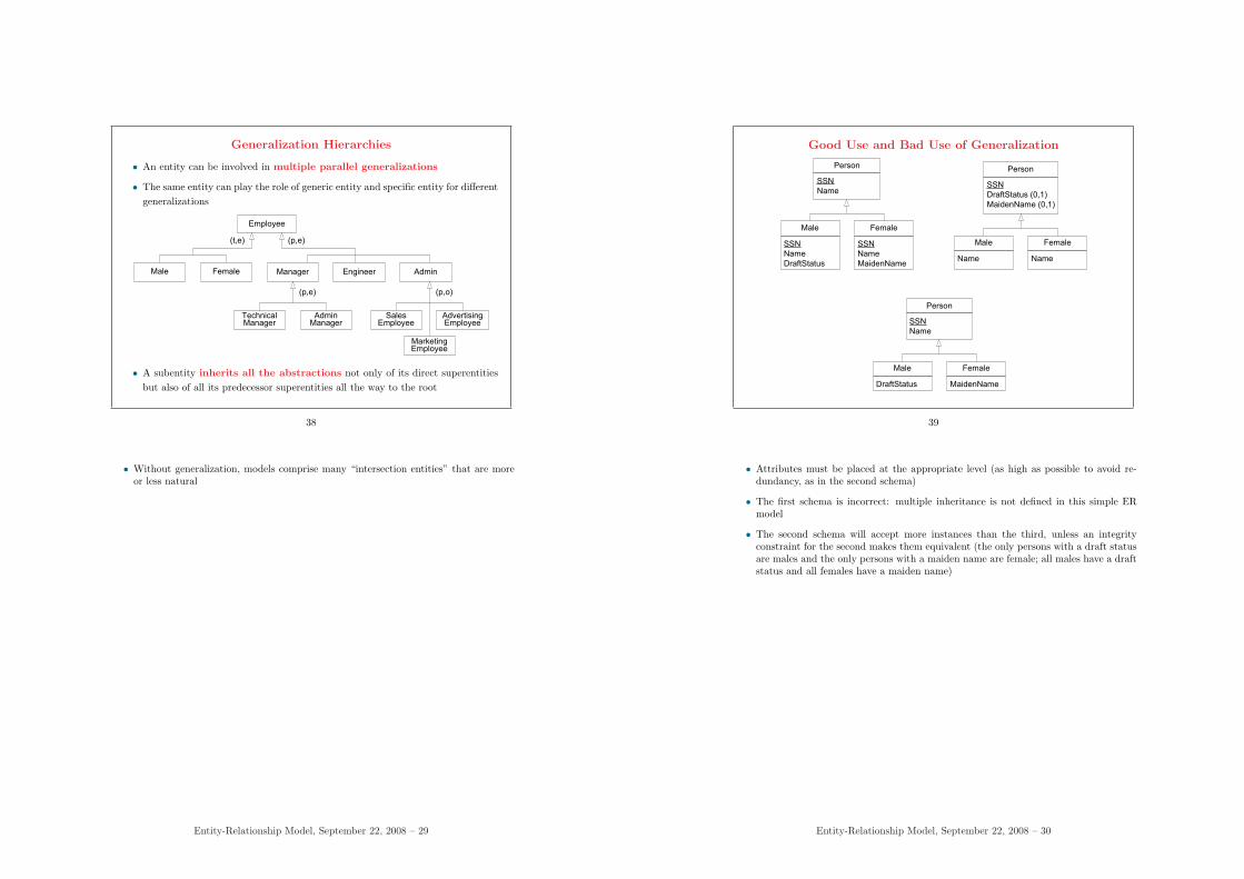
Generalization Hierarchies
• An entity can be involved in multiple parallel generalizations
• The same entity can play the role of generic entity and specific entity for differentgeneralizations
Employee
(t,e)
Manager Engineer AdminMale Female
(p,e)
TechnicalManager
AdminManager
SalesEmployee
MarketingEmployee
AdvertisingEmployee
(p,e) (p,o)
• A subentity inherits all the abstractions not only of its direct superentitiesbut also of all its predecessor superentities all the way to the root
38
• Without generalization, models comprise many “intersection entities” that are moreor less natural
Entity-Relationship Model, September 22, 2008 – 29
Good Use and Bad Use of Generalization
Person
Male Female
SSN
Name
SSN
Name
DraftStatus
SSN
Name
MaidenName
Person
Male Female
SSN
Name
DraftStatus MaidenName
Person
Male Female
SSN
DraftStatus (0,1)
MaidenName (0,1)
Name Name
39
• Attributes must be placed at the appropriate level (as high as possible to avoid re-dundancy, as in the second schema)
• The first schema is incorrect: multiple inheritance is not defined in this simple ERmodel
• The second schema will accept more instances than the third, unless an integrityconstraint for the second makes them equivalent (the only persons with a draft statusare males and the only persons with a maiden name are female; all males have a draftstatus and all females have a maiden name)
Entity-Relationship Model, September 22, 2008 – 30
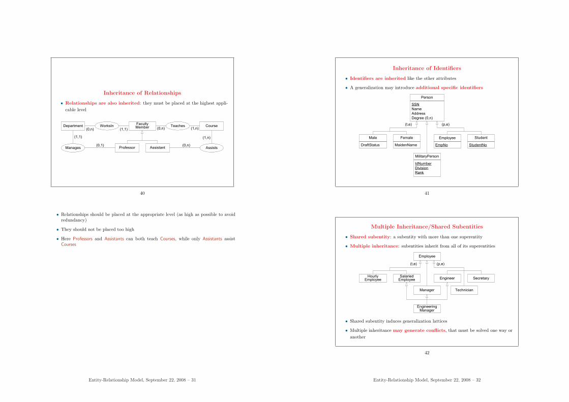
Inheritance of Relationships
• Relationships are also inherited: they must be placed at the highest appli-cable level
(0,n)
FacultyMember Teaches
(1,n)(1,1)WorksInDepartment Course
Professor AssistantManages Assists
(0,n)
(0,n)
(1,n)(1,1)
(0,1)
40
• Relationships should be placed at the appropriate level (as high as possible to avoidredundancy)
• They should not be placed too high
• Here Professors and Assistants can both teach Courses, while only Assistants assistCourses
Entity-Relationship Model, September 22, 2008 – 31
Inheritance of Identifiers
• Identifiers are inherited like the other attributes
• A generalization may introduce additional specific identifiers
Person
SSN
Name
Address
Degree (0,n)
(t,e)
Male Female
DraftStatus MaidenName
MilitaryPerson
IdNumber
Division
Rank
Employee
(p,e)
EmpNo
Student
StudentNo
41
Multiple Inheritance/Shared Subentities
• Shared subentity: a subentity with more than one superentity
• Multiple inheritance: subentities inherit from all of its superentities
Employee
(t,e)
Manager
Engineer
Technician
SecretaryHourly
EmployeeSalariedEmployee
(p,e)
EngineeringManager
• Shared subentity induces generalization lattices
• Multiple inheritance may generate conflicts, that must be solved one way oranother
42
Entity-Relationship Model, September 22, 2008 – 32
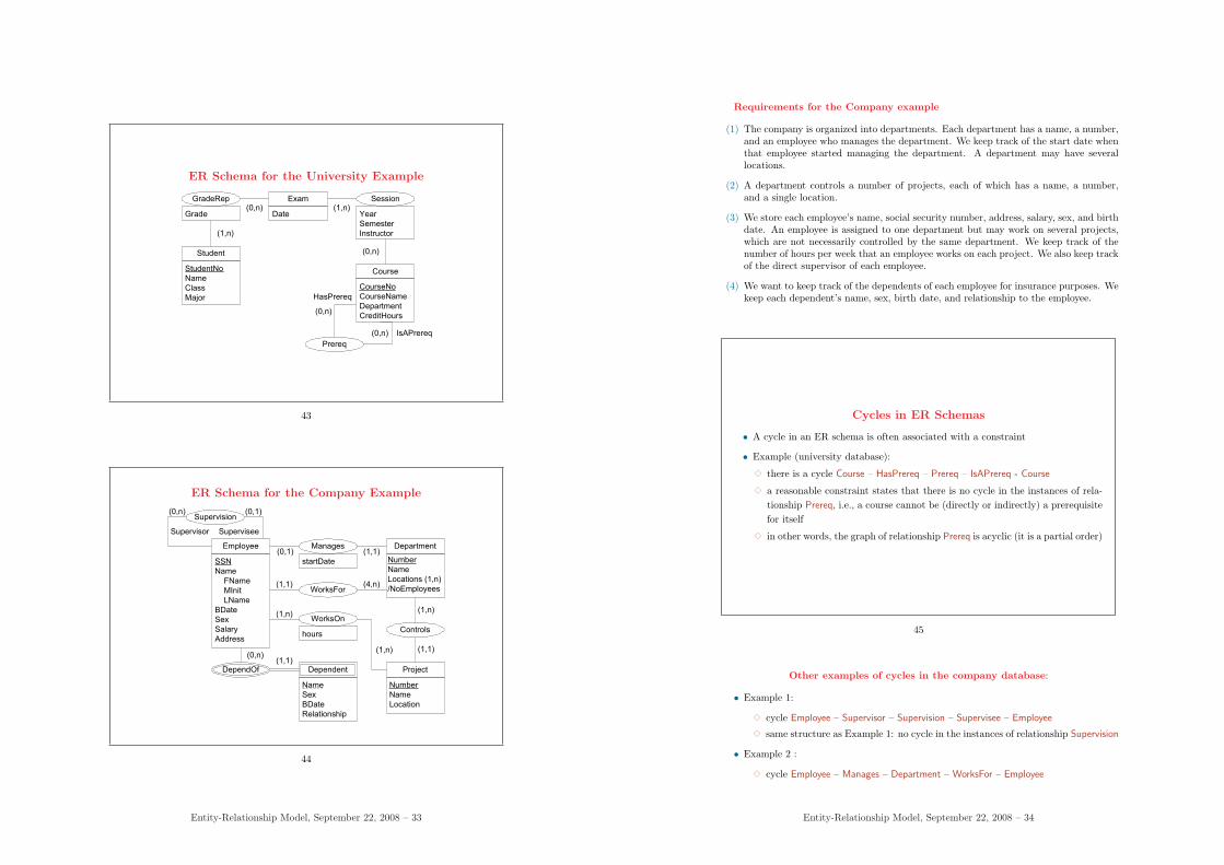
ER Schema for the University Example
(0,n)
Student
StudentNo
Name
Class
Major
Exam Session
Course
CourseNo
CourseName
Department
CreditHours
Prereq
(1,n)
(0,n)
(1,n)
GradeRep
Grade
(0,n)
(0,n)
HasPrereq
IsAPrereq
Year
Semester
Instructor
Date
43
ER Schema for the Company Example
WorksFor
(1,1)
(4,n)
Employee
SSN
Name
FName
MInit
LName
BDate
Sex
Salary
Address
Department
Number
Name
Locations (1,n)
/NoEmployees
Controls
Project
Number
Name
Location
WorksOn
hours
Supervision
(1,n)
(1,n)
(1,n)
(1,1)
(1,1)
(0,1)
(0,1)(0,n)
SuperviseeSupervisor
Manages
startDate
Name
Sex
BDate
Relationship
DependOf
(0,n)(1,1)
Dependent
44
Entity-Relationship Model, September 22, 2008 – 33
Requirements for the Company example
(1) The company is organized into departments. Each department has a name, a number,and an employee who manages the department. We keep track of the start date whenthat employee started managing the department. A department may have severallocations.
(2) A department controls a number of projects, each of which has a name, a number,and a single location.
(3) We store each employee’s name, social security number, address, salary, sex, and birthdate. An employee is assigned to one department but may work on several projects,which are not necessarily controlled by the same department. We keep track of thenumber of hours per week that an employee works on each project. We also keep trackof the direct supervisor of each employee.
(4) We want to keep track of the dependents of each employee for insurance purposes. Wekeep each dependent’s name, sex, birth date, and relationship to the employee.
Cycles in ER Schemas
• A cycle in an ER schema is often associated with a constraint
• Example (university database):
3 there is a cycle Course – HasPrereq – Prereq – IsAPrereq - Course
3 a reasonable constraint states that there is no cycle in the instances of rela-tionship Prereq, i.e., a course cannot be (directly or indirectly) a prerequisitefor itself
3 in other words, the graph of relationship Prereq is acyclic (it is a partial order)
45
Other examples of cycles in the company database:
• Example 1:
3 cycle Employee – Supervisor – Supervision – Supervisee – Employee
3 same structure as Example 1: no cycle in the instances of relationship Supervision
• Example 2 :
3 cycle Employee – Manages – Department – WorksFor – Employee
Entity-Relationship Model, September 22, 2008 – 34
3 plausible constraint: every employee who manages a department also works forthat department
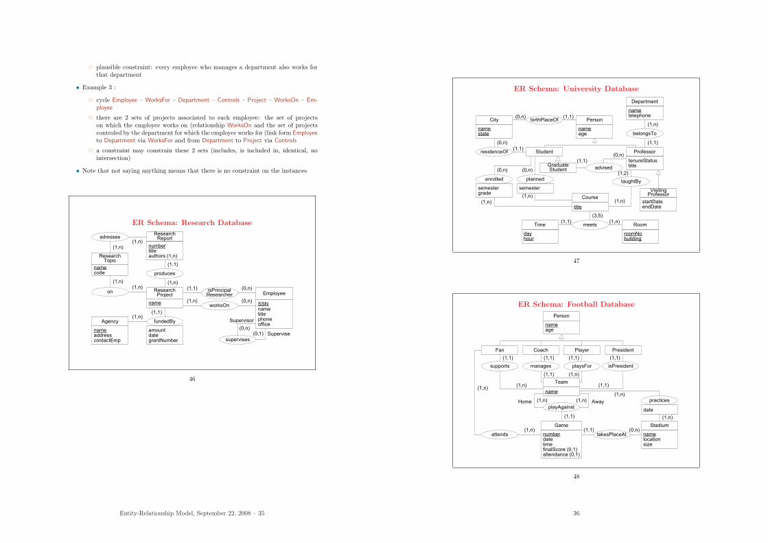
• Example 3 :
3 cycle Employee – WorksFor – Department – Controls – Project – WorksOn – Em-ployee
3 there are 2 sets of projects associated to each employee: the set of projectson which the employee works on (relationship WorksOn and the set of projectscontroled by the department for which the employee works for (link form Employeeto Department via WorksFor and from Department to Project via Controls
3 a constraint may constrain these 2 sets (includes, is included in, identical, nointersection)
• Note that not saying anything means that there is no constraint on the instances
ER Schema: Research Database
nameaddresscontactEmp
ResearchReport
numbertitleauthors (1,n)
fundedBy
(1,1)
Agency
SSNnametitlephoneoffice
Employee
supervises
worksOn
(0,1)
produces
ResearchProject
(1,n)
(1,1)
on
ResearchTopic
adresses(1,n)
(1,n)
namecode
name
amountdategrantNumber
isPrincipalResearcher
(0,n)
Supervisor
Supervise
(0,n)
(0,n)(1,1)
(1,n)
(1,n)(1,n)
(1,n)
46
Entity-Relationship Model, September 22, 2008 – 35
ER Schema: University Database
dayhour
GraduateStudent
Professor
enrolled
Person
nameage
VisitingProfessor
Student
planned
advised
taughtBy
Course
(1,1)
(1,1)
(1,2)
(1,n)
meets
title
(3,5)
Time
roomNobuilding
Room
(1,n)
(1,1) (1,n)
birthPlaceOfCity
namestate
(1,1)(0,n)
residenceOf
belongsTo
Department
nametelephone
tenureStatustitle
startDateendDate
(1,n)
semestergrade
semester
(1,n)
(0,n) (0,n)
(1,1)
(0,n)
(0,n)
47
ER Schema: Football Database
numberdatetimefinalScore (0,1)attendance (0,1)
attends
Coach Player
supports
Person
nameage
(1,n)
(1,1)
PresidentFan
manages playsFor isPresident
Team
(1,1) (1,1) (1,1)
(1,1) (1,n)
(1,1)
playAgainst
name
Home Away(1,n)(1,n)
Game
namelocationsize
Stadium
(1,n)
(1,n)takesPlaceAt
practices
date
(1,1)
(1,1) (0,n)
(1,n)
(1,n)
48
36