Embed Size (px)
Citation preview

Cover
ARMY RESERVE Design Process and Submittal Requirements
PART B DETAILED DESIGN (PHASE II) --
DESIGN/BID/BUILD
1 April 2007

TABLE OF CONTENTS
PART B – DETAILED DESIGN (PHASE II).......................................................................................... 1
Chapter 1.0 – ALL DISCIPLINES........................................................................................................ 1 1.1 GENERAL................................................................................................................... 1 1.2 REFERENCE DOCUMENTS..................................................................................... 1 1.3 ENERGY CONSERVATION AND LIFE CYCLE COST ANALYSIS .................... 5 1.4 BIM (Building Information Model) ............................................................................ 5 1.5 PHASE II–CHARRETTE DESIGN MEETING AND SUBMITTAL....................... 6 1.6 PHASE II–INTERIM DESIGN SUBMITTAL ........................................................... 9 1.7 PHASE II–FINAL DESIGN SUBMITTAL .............................................................. 10 1.8 PHASE II–CORRECTED FINAL DESIGN SUBMITTAL AND REVIEW ........... 12 1.9 CERTIFIED FINAL DESIGN SUBMITTAL........................................................... 13 1.10 READY TO ADVERTISE (RTA)............................................................................. 13 1.11 ADVERTISE ............................................................................................................. 14 1.12 ISSUE ........................................................................................................................ 14 1.13 AMENDMENTS ....................................................................................................... 14 1.14 BID OPENING & AWARD ...................................................................................... 14 1.15 AS AWARDED DOCUMENTS ............................................................................... 14 1.16 RENDERINGS .......................................................................................................... 15
Chapter 2.0 – CIVIL............................................................................................................................. 16 2.1 GENERAL................................................................................................................. 16 2.2 PHASE II–CHARRETTE DESIGN .......................................................................... 17 2.3 PHASE II–INTERIM DESIGN ................................................................................. 17 2.4 PHASE II–FINAL DESIGN...................................................................................... 18
Chapter 3.0 – SITE MECHANICAL UTILITIES............................................................................. 20 3.1 GENERAL................................................................................................................. 20 3.2 PHASE II–CHARRETTE DESIGN .......................................................................... 20 3.3 PHASE II–INTERIM DESIGN ................................................................................. 20 3.4 PHASE II–FINAL DESIGN...................................................................................... 21
Chapter 4.0 – ARCHITECTURAL..................................................................................................... 22 4.1 GENERAL................................................................................................................. 22 4.2 PHASE II–CHARRETTE DESIGN .......................................................................... 24 4.3 PHASE II–INTERIM DESIGN ................................................................................. 24 4.4 PHASE II–FINAL DESIGN...................................................................................... 25
Chapter 5.0 –INTERIOR DESIGN..................................................................................................... 27 5.1 GENERAL................................................................................................................. 27 5.2 PHASE II–CHARRETTE DESIGN .......................................................................... 28 5.3 PHASE II–INTERIM DESIGN ................................................................................. 28 5.4 PHASE II–FINAL DESIGN...................................................................................... 30
Chapter 6.0 – STRUCTURAL............................................................................................................. 35 6.1 GENERAL................................................................................................................. 35 6.2 PHASE II–CHARRETTE DESIGN .......................................................................... 35 6.3 PHASE II–INTERIM DESIGN ................................................................................. 35 6.4 PHASE II–FINAL DESIGN...................................................................................... 36
Chapter 7.0 – MECHANICAL – HVAC, PLUMBING, AND FIRE PROTECTION................... 38 7.1 GENERAL................................................................................................................. 38 7.2 PHASE II–CHARRETTE DESIGN .......................................................................... 38 7.3 PHASE II–INTERIM DESIGN ................................................................................. 39

7.4 PHASE II–FINAL DESIGN...................................................................................... 41 Chapter 8.0 –ELECTRICAL............................................................................................................... 44
8.1 GENERAL................................................................................................................. 44 8.2 PHASE II–CHARRETTE DESIGN .......................................................................... 45 8.3 PHASE II–INTERIM DESIGN ................................................................................. 47 8.4 PHASE II–FINAL DESIGN...................................................................................... 50
Chapter 9.0 – COST ENGINEERING................................................................................................ 52 9.1 GENERAL................................................................................................................. 52 9.2 PHASE II–CHARRETTE DESIGN .......................................................................... 54 9.3 PHASE II–INTERIM DESIGN ................................................................................. 54 9.4 PHASE II–FINAL DESIGN...................................................................................... 55
Chapter 10.0 – ENVIRONMENTAL .................................................................................................. 56 10.1 GENERAL................................................................................................................. 56 10.2 PHASE II–CHARRETTE DESIGN, INTERIM DESIGN, AND FINAL DESIGN. 56
APPENDIX................................................................................................................................................ 57
APPENDIX TOC
(Separately Bound)
APPENDIX 1 – BIM INSTRUCTIONS APPENDIX 2 – BIM SUBMITTAL REQUIREMENTS APPENDIX – SAMPLE TYPED SUMMARY ESTIMATE

Page 1
U.S. ARMY RESERVE Design Process and Submittal Requirements
PART B – DETAILED DESIGN (PHASE II)
Chapter 1.0 – ALL DISCIPLINES
1.1 GENERAL This portion of the Army Reserve Design Process and Submittal Requirements manual describes development of project detailed designs – the working drawings, specifications and other docu-ments that make up the completed project design documents.
Note: This portion of the Manual is called Part B. It is specific to Design/Bid/Build projects. There are two other parts, described below for general information only.
• DPSR manual Part A -- Project Inception and Project Definition provides background information. It describes the Inception and Project Definition steps of Army Reserve pro-jects. It begins with the Budget Process and ends with Project Definition (Phase I) wherein the project is sufficiently defined to allow detailed design. Part A may be of general interest to the D/B/Build designer, but it does not extend the requirements of D/B/B as described in Part B and is not a part of this Part B.
• DPSR manual Part C -- Design Build -- Design Submittal Requirements After Award is specific to Design Build projects, and is for use by the successful D/B contractor. It has no requirements concerning D/B/B and is not a part of this Part B.
1.2 REFERENCE DOCUMENTS The listings and table below are a summary listing of the major reference documents for perform-ance of the detailed design.
*Note: Reference documents dates shown were current at the time of production of this Manual, Summer and Fall 2006. Where documents have been superseded by later versions of the docu-ment or by replacement documents, refer to those later documents.
A-E Contract-related Documents:
EP 715-1-7 Architect-Engineer Contracting 31 Jul 02
CEMP-E (Corps HQ) Architectural and Engineering Instructions-Design Criteria, 03 July 1994.
A-E's Contract Appendix A (SOW), date as noted in paragraph Authorization above
DESIGN REFERENCE DOCUMENTS:
All Design Disciplines ADA-AG Americans with Disabilities Act – Accessibility Guidelines **These new guidelines replace the ADAAG and UFAS stan-
1 April 2007 Version Army Reserve DPSR Manual -- Part B

Page 2
** Revised ADA-ABA Guidelines
dards cited above, when adopted. As of this writing (Decem-ber 2006) most federal agencies except DoD have adopted the new guidelines. DOD has not yet indicated when its adoption of new standards will take place. Updates may be found at http://www.access-board.gov/ada-aba/index.htm
AR 190-11 Physical Security of Weapons, Ammunition, and Explosives 12 February 1998
ASCE 7-02 Minimum Design Loads for Buildings and Other Structures ASHRAE 90.1-2004 Energy Standard for Buildings Except Low-Rise Residential
Buildings (Continuous Maintenance Standard) Note: Energry Policy Act of 2005 makes specific reference to the 2004 ver-sion.
BIM Refer to the Appendices to this DPSR manual. ECB 2003-20 Engineering and Construction Bulletin, Sustainable Project
Rating Tool
IBC International Building Code, 2003 LDDG Louisville District Design Guide (LDDG)
http://www.lrl.usace.army.mil/ed2/ (on-line edition) M-CACES Micro-computer Army Cost Estimating S Composer Plus M-
CACES edition users manual, program and database diskettes system
NFPA 30A Code for Motor Fuel Dispensing Facilities and Repair Garages, dated 7 August 2003
NFPA 101 Life Safety Code 2006 Edition No Number Louisville District CADD Standard Details. (This document) ARMY RESERVE Design Process and Submittal Require-
ments TI 800-01 Design Criteria 20 July 1998 UFC (index)
Index of Unified Facilities Criteria, current listing. http://www.wbdg.org/ccb/browse_cat.php?o=29&c=4
UFC 1-200-01 Design: General Building Requirements20 June 2005 UFC 3-310-01 Structural Load Data 25 May 2005 UFC 3-400-01 Design: Energy Conservation 5 July 2002 UFC 3-490-04A Design: Indoor Radon Prevention and Mitigation 15-May-03 UFC 3-600-01 Fire Protection Engineering for Facilities 26 September 2006 UFC 3-700-02A Construction Cost Estimates 01 March 2005 (is former EI
01D010 1 September 1997) UFC 4-010-01 Design: DoD Minimum Antiterrorism Standards for Buildings
08-Oct-03 UFC 4-010-02 Design (FOUO): DoD Minimum Standoff Distances for Build-
ings 08-Oct-03 UFC 4-171-05 Army Reserve Facilities 25 Oct 2006
http://www.wbdg.org/ccb/DOD/UFC/ufc_4_171_05.pdf Other General References: AFETL
Air Force Engineer Technical Letters http://www.wbdg.org/ccb/browse_cat.php?o=33&c=125
1 April 2007 Version Army Reserve DPSR Manual -- Part B

Page 3
ANSI American National Standard Institute http://www.ansi.org/ ETL Engineer Technical Letters
http://www.hnd.usace.army.mil/TECHINFO/engpubs.htm ER
Engineering Regulations http://www.hnd.usace.army.mil/TECHINFO/engpubs.htm
MIL-HDBK
Military Handbooks http://www.wbdg.org/ccb/browse_cat.php?o=31&c=104
NFPA Na-tional Fire Protection Association http://www.nfpa.org/index.asp
RST04 Louisville District Army Reserve Specifications (AR) http://www.lrl.usace.army.mil/ed/specs.asp
TM
Department of the Army Technical Manuals http://www.usace.army.mil/publications/
UFC United Facility Criteria http://www.hnd.usace.army.mil/TECHINFO/engpubs.htm
UFAS Uniform Federal Accessibility Standards, 1984 UFGS, and LRL and RST adapta-tions
United Facility Guide Specifications http://www.hnd.usace.army.mil/TECHINFO/engpubs.htm , or http://www.wbdg.org/ccb/ Louisville and Army Reserve adaptations of these specs can be found on the Louisville District web site at http://www.lrl.usace.army.mil/ed/specs.asp
USAR CIO Information Technology Requirements for Military Construc-tion Army Reserve. http://www.lrl.usace.army.mil/ed2/article.asp?id=196
Civil and Site Utilities Standard Specifications for Con-struction and Materials
State of [ ] Department of Transportation
UFC 3-230-10A Water Supply, Water Distribution 16 January 2004 UFC 3-250-01FA Pavement Design for Roads, Streets, Walks and Open Storage
Areas 16 January 2004 UFC 3-250-03 Standard Practice Manual for Flexible Pavements 16 January
2004 UFC 3-250-04FA Standard Practice for Concrete Pavements UFC 3-250-18FA General Provisions and Geometric Design for Roads, Streets,
Walks and Open Storage Areas 6 January 2006 * Those listed under "All Design Disciplines" above.
Architectural/Interior Design AR 190-51 Security Of Unclassified Army Property (Sensitive And Non-
sensitive) 30 September 1993 ASHRAE Standard 90.1-2004 Standard 90.1-2004 -- Energy Standard for Buildings Except
Low-Rise Residential Buildings (Continuous Maintenance Standard)
NFPA 80 Fire Doors and Windows UFC 3-120-01 Air Force Sign Standard 02-06-2003
1 April 2007 Version Army Reserve DPSR Manual -- Part B
Page 4
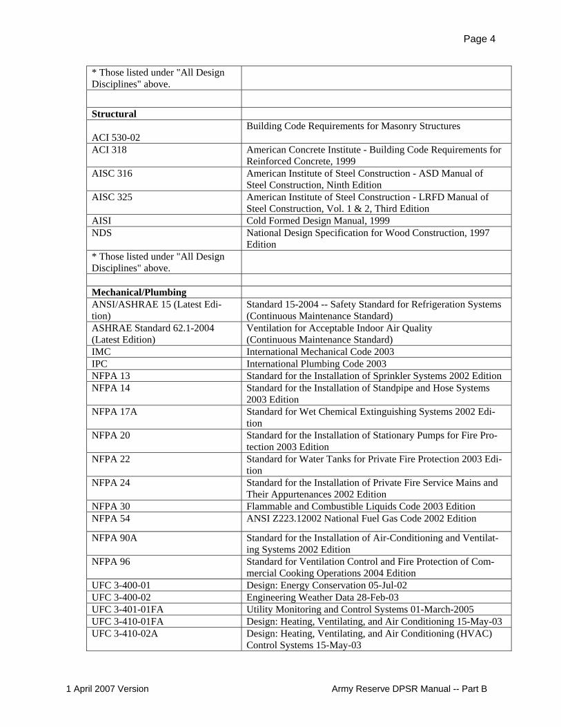
* Those listed under "All Design Disciplines" above.
Structural ACI 530-02
Building Code Requirements for Masonry Structures
ACI 318 American Concrete Institute - Building Code Requirements for Reinforced Concrete, 1999
AISC 316 American Institute of Steel Construction - ASD Manual of Steel Construction, Ninth Edition
AISC 325 American Institute of Steel Construction - LRFD Manual of Steel Construction, Vol. 1 & 2, Third Edition
AISI Cold Formed Design Manual, 1999 NDS National Design Specification for Wood Construction, 1997
Edition * Those listed under "All Design Disciplines" above.
Mechanical/Plumbing ANSI/ASHRAE 15 (Latest Edi-tion)
Standard 15-2004 -- Safety Standard for Refrigeration Systems (Continuous Maintenance Standard)
ASHRAE Standard 62.1-2004 (Latest Edition)
Ventilation for Acceptable Indoor Air Quality (Continuous Maintenance Standard)
IMC International Mechanical Code 2003 IPC International Plumbing Code 2003 NFPA 13 Standard for the Installation of Sprinkler Systems 2002 Edition NFPA 14 Standard for the Installation of Standpipe and Hose Systems
2003 Edition NFPA 17A Standard for Wet Chemical Extinguishing Systems 2002 Edi-
tion NFPA 20 Standard for the Installation of Stationary Pumps for Fire Pro-
tection 2003 Edition NFPA 22 Standard for Water Tanks for Private Fire Protection 2003 Edi-
tion NFPA 24 Standard for the Installation of Private Fire Service Mains and
Their Appurtenances 2002 Edition NFPA 30 Flammable and Combustible Liquids Code 2003 Edition NFPA 54 ANSI Z223.12002 National Fuel Gas Code 2002 Edition
NFPA 90A Standard for the Installation of Air-Conditioning and Ventilat-ing Systems 2002 Edition
NFPA 96 Standard for Ventilation Control and Fire Protection of Com-mercial Cooking Operations 2004 Edition
UFC 3-400-01 Design: Energy Conservation 05-Jul-02 UFC 3-400-02 Engineering Weather Data 28-Feb-03 UFC 3-401-01FA Utility Monitoring and Control Systems 01-March-2005 UFC 3-410-01FA Design: Heating, Ventilating, and Air Conditioning 15-May-03 UFC 3-410-02A Design: Heating, Ventilating, and Air Conditioning (HVAC)
Control Systems 15-May-03
1 April 2007 Version Army Reserve DPSR Manual -- Part B
Page 5
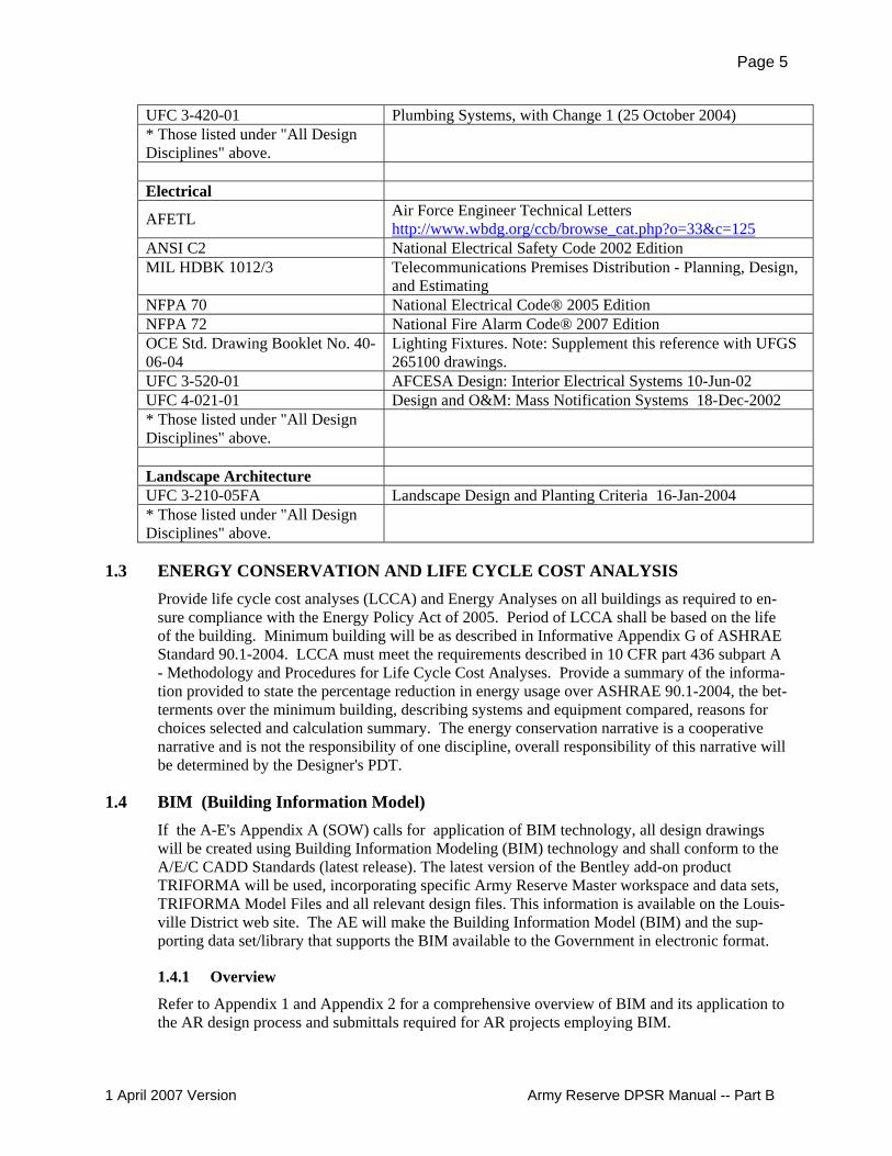
UFC 3-420-01 Plumbing Systems, with Change 1 (25 October 2004) * Those listed under "All Design Disciplines" above.
Electrical
AFETL Air Force Engineer Technical Letters http://www.wbdg.org/ccb/browse_cat.php?o=33&c=125
ANSI C2 National Electrical Safety Code 2002 Edition MIL HDBK 1012/3 Telecommunications Premises Distribution - Planning, Design,
and Estimating NFPA 70 National Electrical Code® 2005 Edition NFPA 72 National Fire Alarm Code® 2007 Edition OCE Std. Drawing Booklet No. 40-06-04
Lighting Fixtures. Note: Supplement this reference with UFGS 265100 drawings.
UFC 3-520-01 AFCESA Design: Interior Electrical Systems 10-Jun-02 UFC 4-021-01 Design and O&M: Mass Notification Systems 18-Dec-2002 * Those listed under "All Design Disciplines" above.
Landscape Architecture UFC 3-210-05FA Landscape Design and Planting Criteria 16-Jan-2004 * Those listed under "All Design Disciplines" above.
1.3 ENERGY CONSERVATION AND LIFE CYCLE COST ANALYSIS Provide life cycle cost analyses (LCCA) and Energy Analyses on all buildings as required to en-sure compliance with the Energy Policy Act of 2005. Period of LCCA shall be based on the life of the building. Minimum building will be as described in Informative Appendix G of ASHRAE Standard 90.1-2004. LCCA must meet the requirements described in 10 CFR part 436 subpart A - Methodology and Procedures for Life Cycle Cost Analyses. Provide a summary of the informa-tion provided to state the percentage reduction in energy usage over ASHRAE 90.1-2004, the bet-terments over the minimum building, describing systems and equipment compared, reasons for choices selected and calculation summary. The energy conservation narrative is a cooperative narrative and is not the responsibility of one discipline, overall responsibility of this narrative will be determined by the Designer's PDT.
1.4 BIM (Building Information Model) If the A-E's Appendix A (SOW) calls for application of BIM technology, all design drawings will be created using Building Information Modeling (BIM) technology and shall conform to the A/E/C CADD Standards (latest release). The latest version of the Bentley add-on product TRIFORMA will be used, incorporating specific Army Reserve Master workspace and data sets, TRIFORMA Model Files and all relevant design files. This information is available on the Louis-ville District web site. The AE will make the Building Information Model (BIM) and the sup-porting data set/library that supports the BIM available to the Government in electronic format.
1.4.1 Overview
Refer to Appendix 1 and Appendix 2 for a comprehensive overview of BIM and its application to the AR design process and submittals required for AR projects employing BIM.
1 April 2007 Version Army Reserve DPSR Manual -- Part B

Page 6
1.5 PHASE II–CHARRETTE DESIGN MEETING AND SUBMITTAL
1.5.1 General.
The purpose of design phase II is to prepare a complete detailed design. Phase II is divided into three submittals, a Charrette, Interim and Final Design. The goal is to produce a set of construc-tion contract documents ready for bid. This phase begins approximately fifteen months before the fiscal year of construction, when Headquarters Corps of Engineers in Washington (HQUSACE) issues a directive to complete final design phase II. This is ninety days prior to the start of detailed design at the on-site charrette design meeting. Assuming an October meeting date, HQUSACE issues the design directive in July.
1.5.2 Pre-Charrette Actions.
1.5.2.1 The same designers that participated in the Phase I design are to be used on Phase II to the maximum extent possible. ACSIM-AR will be notified when there is a change in designers.
1.5.2.2 The Louisville District Project Manager will ensure the design team receives a copy of the Phase I package and revised project documentation (revised 1391/1390 and 5034R) approximately 45 days before the charrette design meeting.
1.5.2.3 The design team will prepare for the charrette design meeting. One week prior to the meeting, Designer shall send the charrette documents in PDF format to the charrette meeting participants. Electronic submissions via ftp, an agreed groupware tool such as Microsoft Groove, or email (size permitting) will be acceptable. Design team shall prepare and send out the following documents ahead of the charrette meeting:
a. Two each alternate site layouts and floor plans. b. Floor plan shall be color coded by Reserve Unit occupying the building. Provide
annotation of the units occupying the building for each drill weekend. c. A $/square foot cost comparison of the three alternatives. d. A draft narrative description of the major systems, including roof material,
exterior skin, windows, doors, mechanical units, electrical, structure, finishes, fire protection, mass notification, IT, and any special systems.
e. A draft narrative description of site characteristics, and any special site considerations, site utilities, permits, and foundations, to the extent known.
f. Space Allocation Table. Provide in the same format as the Functional Space Details Worksheet, which is part of the 5034R project documentation.
g. The charrette agenda. Agenda should include breakout sessions by discipline.
1.5.3 Charrette Meeting.
Detailed design begins at the Charrette design meeting. It takes place on or near the site and uses a charrette process to arrive at a mutually acceptable design solution. This process is character-ized by an informal and free exchange of information and ideas between users and designers that establish project requirements. Charrette participants are encouraged to bring their ideas to the meeting, with no formal comment collection and response required or desired beforehand. A typical design team consists of the designer’s project manager, lead architect, civil engineer, inte-rior design, electrical/IT, mechanical engineer and CADD/BIM technical support. This may be adjusted based on SOW, agreement with the PE/A and evaluation of the requirements by the de-sign team leader. The various requirements are evaluated and prioritized and incorporated into the project based on group consensus as monitored by the Corps' Project Manager. The meeting can last two or more days.
1 April 2007 Version Army Reserve DPSR Manual -- Part B

Page 7
It is desirable if the PM and user arrange for the users, the installation, and DPW and utility peo-ple, ISEC and other communications people to attend the meeting and discuss the utilities / elec-trical / communications / mechanical / fire protection in breakouts. In consideration of these peo-ple's time, it is desirable that each is accorded a specific time slot in the schedule, and the sched-ule be adhered to.
1.5.3.1 Design Process. Design decisions at this meeting are final. It should be emphasized to all team members that this is the case. Attendees must be decision-makers. This is the last opportunity to change functional requirements. All major site features and floor plans are finalized at this meeting. It may require participants to maintain continuous dialogue with off-site experts and commanders during the meeting to obtain information, guidance, and approvals.
1.5.3.2 Color Scheme. Select one of the four Reserve interior color schemes. The design team shall bring for discussion color samples of the four schemes.
1.5.3.3 Facilities. Administrative support is crucial to this type of process. Normally, the government provides space at or near the site to accommodate a large meeting and separate, smaller sessions. If so scoped and directed in the SOW, the A-E may arrange for and provide the facility. The facility must have workspace with chairs, tables, and sufficient electrical outlets to accommodate the use of computers. The designers use Bentley Design Solutions software for the design during the meeting, and some other attendees will probably bring laptops as well. The design team will provide computers, software, overhead projectors, presentation materials and equipment needed on site to produce CADD design files, small (8.5 x 11 inch) design drawings, and meeting minutes. Design team will provide 1 full-sized set of the drawings described above under subparagraph "Pre-Charrette Actions", and may wish to bring additional spare reduced-size copies of the drawings for anyone who does not have printouts of the PDF sets that were electronically distributed earlier.
1.5.3.4 Presentation. In the opening session, the ACSIM-AR project officer elaborates, as needed, to explain key functional relationships, desired features, and other important considerations.
a. The design team will present the Charrette Documents, including alternative site and building layouts.
b. The design team reviews possible LEED rating system "points" that require a commitment from the owners, (e.g. Training, use of Green Power, etc.) and obtains an agreement that these points are or are not available to the designer of the project toward meeting the LEED rating goals.
1.5.3.5 Design Iteration. After the initial session, the designers begin detailed work, walking the site, coordinating with local utility providers and regulatory agencies, and revising site and space layout schemes. Breakout sessions of all disciplines should occur. Other members of the PDT remain available for consultation. When the designer is ready, the other participants reconvene to hear and discuss the design proposal, eliminate alternatives, and provide additional guidance. The group adjourns again, while the designer refines the design to incorporate the latest comments. This is an iterative process, which continues until the design is acceptable, and the project delivery team selects the preferred site and building scheme to develop.
1.5.3.6 The end result of the charrette is an agreement on the following:
a. Site Plan. Plan will show building footprints, AT/FP setbacks, POV parking, MEP, and access roads. Indicate the general location of new buildings, paved
1 April 2007 Version Army Reserve DPSR Manual -- Part B

Page 8
areas, structures, fences, ramps and curbs. On the property. Locate the building from a known point of reference. Indicate areas for parking privately owned vehicles (POV) and military equipment (MEP).
b. Space Layout. (Single line floor plans, provided for each building) c. Selected Army Reserve color scheme, and finishes. d. Wrap-up, including
1) Design summary 2) Schedule, including scheduling the revised charrette conference call. 3) Action items 4) Participants receive outline meeting minutes and a list of participants.
e. Deliverables: The design agent (A-E or Corps in-house) provides participants with outline meeting minutes, a list of participants, electronic copies of the draft design files (PDF format), and reproduced paper markups sufficient to define the results of the meeting.
1.5.4 Submittal Requirements.
1.5.4.1 Charrette meeting: The items listed above in paragraph just above beginning with words "The end result . . .".
1.5.4.2 Revised Charrette Document: The revised charrette document will be submitted to the PDT after the charrette meeting in the time called for in the schedule. This would typically be approximately three weeks after the charrette meeting. It consists of meeting minutes, updated narrative, image files, and a parametric cost estimate. Note that this is not an opportunity to revise functional space. All those decisions are final at the adjournment of the charrette meeting. The designer in some instances may make minor changes after the meeting, such as enlarging the telecommunications closets to accommodate bulkier-than-anticipated equipment. Provide the following:
a. Design Narrative; This narrative will contain meeting minutes that provide a thorough record of discussions, iterations, and decisions from the charrette design meeting. Describe the proposed architectural, civil, mechanical, structural and electrical design. List special equipment with unusually large electrical or cooling loads. Identify which options are used for major building systems. Identify elements outside of the norm such as deep foundations, environmental remediation, etc. that will significantly impact the cost. Describe the interior design features and furnishings intent along with the proposed information systems. Provide information on any known utility conflicts or capacity upgrades that are required for the project. The drawings required below may be properly scaled to fit in the back of the design narrative as foldouts or provided separately.
b. Site Plan. Revise the Project Definition site plan per the charrette meeting. Show handicapped parking and ramps as required. Indicate the dumpster location and screen walls as required. Show the work area limits.
c. Architectural Floor Plans. Complete the floor plans showing the correct room names and numbers, wall locations, toilet fixtures, lockers, folding partitions, storage cages, doors, and the common administration area workstations.
d. Cost Estimate. The Project Definition (Phase I) cost estimate is revised to reflect decisions made at the charrette meeting. Submit the formal estimate at the end of charrette design phase.
1.5.5 Review.
The submittal is sent to the charrette meeting participants to document agreements made at the
1 April 2007 Version Army Reserve DPSR Manual -- Part B

Page 9
charrette meeting. There is usually no review meeting; however a conference call is typical. The purpose of the conference call is to verify the submitted floor plan and other submitted documents are as agreed. Any new changes to the revised charrette documents must be approved by the Project Officer and will be incorporated in the interim design submittal.
1.6 PHASE II–INTERIM DESIGN SUBMITTAL
1.6.1 General.
Interim submittal will be per the schedule. It typically occurs approximately halfway through the final design phase. It is for technical review of the design. It is not a functional review. It in-cludes:
1.6.1.1 Drawings depicting major components of the civil, architectural, interior design, structural, mechanical, electrical, fire protection, and information systems design as well as complete building elevations.
1.6.1.2 A design analysis that contains a narrative by each discipline. Each discipline narrative will list major deviations from the standards in UFC 4-171-05 Army Reserve Facilities. Include as appendixed material minutes of prior meetings the current project 1391, and functional Space Functional Space Details Worksheet, (5034R data).
1.6.1.3 LEED spreadsheet
1.6.1.4 A list of proposed project specifications. These will be included in the Design Analysis.
1.6.1.5 An estimate. Refer to the Chapter "Cost Engineering" for specific requirements.
The design effort continues during the review process.
1.6.2 Submittal Requirements.
As listed above, plus see the discipline chapters for additional specific submittal requirements.
1.6.3 Checking.
All drawings and calculations are checked as required by the project’s Approved Quality Control Plan.
1.6.4 Review.
1.6.4.1 All review comments will be submitted in Dr Checks. The design team shall respond to the DrChecks comments before the review meeting, and bring 25 copies of the latest DrChecks comment report for distribution at the meeting. The A/E may elect to bring 6 copies of the Dr. Checks comments for key players to the meeting, and use an overhead projector for viewing the comments with the entire team to reduce the number of printed copies.
1.6.4.2 There will be an interim design review meeting to discuss review comments and other issues. An onboard type of review conducted at the design agents office is an option. This will be covered in the project Scope of Work (SOW). This may be in the form of an Appendix A to the A-E contract, or when in house the Quality Control Plan. It is anticipated that those DrChecks comments that have not been evaluated and those whose evaluation is not “concur” will be discussed at the review meeting.
1 April 2007 Version Army Reserve DPSR Manual -- Part B

Page 10
Comments with a "Concur" response that is acceptable to Government may not receive further discussion at the meeting.
1.7 PHASE II–FINAL DESIGN SUBMITTAL
1.7.1 General.
The final design submittal consists of a complete design required to build the project. It includes all completed drawings, fully edited specifications and design analysis. The final design is to be completed in accordance with the agreed schedule and delivery date. The final cost estimate must be within the project’s programmed amount (see Chapter: "Cost Engineering" of this Manual), or ACSIM-AR must approve a higher amount.
1.7.2 Comments.
Incorporate all approved interim submittal comments into the design.
1.7.3 Submittal Requirements.
(See also the discipline chapters for specific submittal requirements.)
1.7.3.1 Specifications. Specifications are to be (in order of precedence) Army Reserve specific adaptations of the UFGS specs, Louisville District adaptations of the UFGS, or standard United Facilities Guide Specifications (UFGS). The Louisville and Army Reserve adaptations are available on the Louisville District web site. The specifications are to be edited using SpecsIntact software. The specification document will have an overall index located in the front and each individual specification will have its own separate index. If a particular item is not contained in the UFGS or its adaptations, a new specification must be developed. All new specifications must follow the UFGS format. Usage of product manufacturer’s names is permitted and encouraged only when it is necessary to better establish a standard of quality. If manufacturer’s names are used the applicable specification should list a minimum of three manufacturer’s to the maximum extent possible. This will also help to expedite shop drawing reviews. The usage of manufacturer’s names and products is not to be construed as limiting competition.
1.7.3.2 Design Analysis
a. Provide narrative that is an expansion and elaboration by each discipline from that provided at interim design.
b. Provide design calculations and supporting documentation to support the major technical design considerations. Calculations shall be computed and checked by separate individuals, one of which must be a licensed professional in the associated discipline. Supporting documentation shall be clear, and formulas and references shall be identified. Assumptions and conclusions shall be explained and cross-referencing shall be clear. Provide as called for in the various discipline chapters.
c. Checking 1) All drawings and calculations are checked as required by the project’s
Approved Quality Control Plan. 2) All review comments will be submitted and evaluated in Dr Checks.
d. Cut sheets provided at the design stages are intended only to show the basis of design, and do not create or show a sole-source requirement.
1 April 2007 Version Army Reserve DPSR Manual -- Part B
Page 11
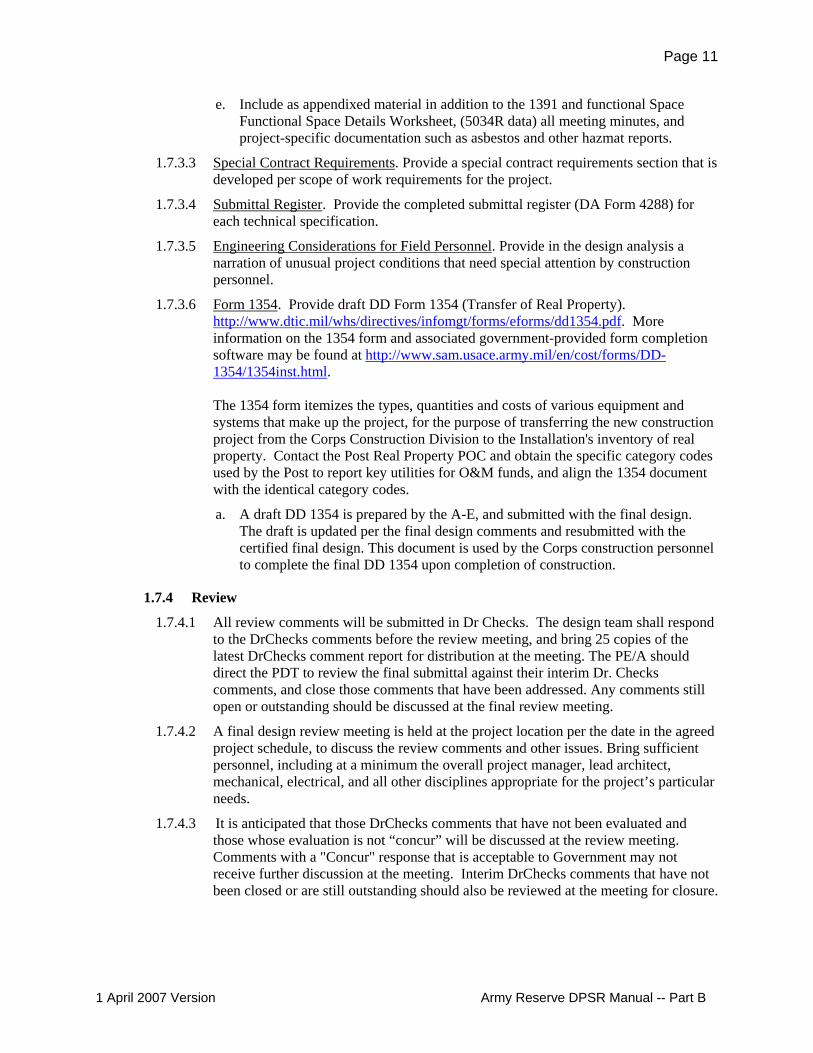
e. Include as appendixed material in addition to the 1391 and functional Space Functional Space Details Worksheet, (5034R data) all meeting minutes, and project-specific documentation such as asbestos and other hazmat reports.
1.7.3.3 Special Contract Requirements. Provide a special contract requirements section that is developed per scope of work requirements for the project.
1.7.3.4 Submittal Register. Provide the completed submittal register (DA Form 4288) for each technical specification.
1.7.3.5 Engineering Considerations for Field Personnel. Provide in the design analysis a narration of unusual project conditions that need special attention by construction personnel.
1.7.3.6 Form 1354. Provide draft DD Form 1354 (Transfer of Real Property). http://www.dtic.mil/whs/directives/infomgt/forms/eforms/dd1354.pdf. More information on the 1354 form and associated government-provided form completion software may be found at http://www.sam.usace.army.mil/en/cost/forms/DD-1354/1354inst.html. The 1354 form itemizes the types, quantities and costs of various equipment and systems that make up the project, for the purpose of transferring the new construction project from the Corps Construction Division to the Installation's inventory of real property. Contact the Post Real Property POC and obtain the specific category codes used by the Post to report key utilities for O&M funds, and align the 1354 document with the identical category codes.
a. A draft DD 1354 is prepared by the A-E, and submitted with the final design. The draft is updated per the final design comments and resubmitted with the certified final design. This document is used by the Corps construction personnel to complete the final DD 1354 upon completion of construction.
1.7.4 Review
1.7.4.1 All review comments will be submitted in Dr Checks. The design team shall respond to the DrChecks comments before the review meeting, and bring 25 copies of the latest DrChecks comment report for distribution at the meeting. The PE/A should direct the PDT to review the final submittal against their interim Dr. Checks comments, and close those comments that have been addressed. Any comments still open or outstanding should be discussed at the final review meeting.
1.7.4.2 A final design review meeting is held at the project location per the date in the agreed project schedule, to discuss the review comments and other issues. Bring sufficient personnel, including at a minimum the overall project manager, lead architect, mechanical, electrical, and all other disciplines appropriate for the project’s particular needs.
1.7.4.3 It is anticipated that those DrChecks comments that have not been evaluated and those whose evaluation is not “concur” will be discussed at the review meeting. Comments with a "Concur" response that is acceptable to Government may not receive further discussion at the meeting. Interim DrChecks comments that have not been closed or are still outstanding should also be reviewed at the meeting for closure.
1 April 2007 Version Army Reserve DPSR Manual -- Part B

Page 12
1.8 PHASE II–CORRECTED FINAL DESIGN SUBMITTAL AND REVIEW
1.8.1 Cost Estimate.
Verify that the PACES or Mii cost estimate is complete. Evaluate the estimate in comparison with the project's CCL. Correlate the final estimate format with any Bid Options that are to be included in the bid documents. Incorporate all cost estimating comments in the Corrected Final Estimate. The A/E shall also provide a completed Bid Schedule or Proposal Schedule with costs associated with each line item. The estimate shall be provided in electronic format -- PDF and native files for review.
1.8.2 Comments incorporation.
Corrected final design will incorporate all approved final submittal review comments into the de-sign and other issues arising at the final review meeting and as agreed.
1.8.2.1 Provide one or more red-lined markup sets of the Plans and Specifications (and Design Analysis if required) indicating the disposition of each Comment. Size shall be 11 x 17 or as called for in Appendix A SOW. Red-lined marked up sets shall be marked with a wide red marker or CADD font, circling the change and marking it with the Commenter's name and the DrChecks comment number. The second set may be a black and white copy of the original. It is intended for one set to be sent to the Louisville District and one set to the Construction District.
1.8.2.2 As called for in Appendix A SOW, provide corrected Design Analysis incorporating final review comments. Unless otherwise noted, electronic copy only is preferred.
1.8.3 Biddability, Constructability, Operability And Environmental Review (BCOE).
1.8.3.1 The final design comments from the Corps of Engineers form the basis of the BCOE review.
1.8.3.2 The Corrected Final Documents shall reflect all comment responses. They are the working documents used by the Government for BCOE review. The A/E's Project Manager is responsible to ensure that ALL comments have been addressed. The Corps of Engineers Construction District must have all their comments satisfied before the COE Louisville District Construction District will sign the BCOE Certification. Once the PE/A receives this document with the signature, then the Louisville District Review Team is responsible for the remaining portion of the certification. To obtain BCOE Certification, all comments must be closed in DrChecks. As called for in the Appendix A (SOW), the A/E will provide two Internal Technical Review (ITR) forms.
a. One form is the Contractor Statement of Technical Review, with signatures by the ITR team. It documents that an ITR was conducted for the project.
b. The other is the Certification of Independent Technical Review, with signatures by a principal of the firm and Design team leader, ITR team leader and other management level reviewers. It certifies that the ITR comments have been considered, concerns identified and their resolution in the corrected documents.
1.8.3.3 The Designer will promptly correct any items discovered the course of BCOE review, and demonstrate satisfactory correction to the PE/A and BCOE team. This is
1 April 2007 Version Army Reserve DPSR Manual -- Part B
Page 13
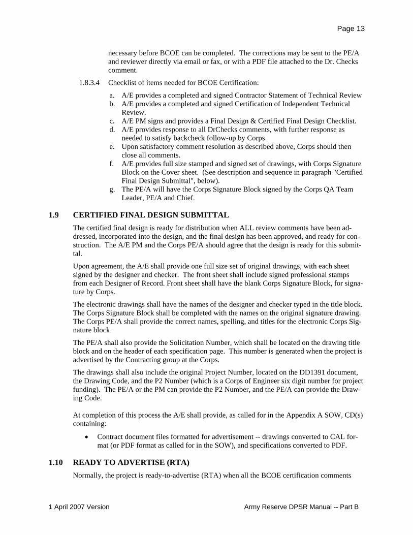
necessary before BCOE can be completed. The corrections may be sent to the PE/A and reviewer directly via email or fax, or with a PDF file attached to the Dr. Checks comment.
1.8.3.4 Checklist of items needed for BCOE Certification:
a. A/E provides a completed and signed Contractor Statement of Technical Review b. A/E provides a completed and signed Certification of Independent Technical
Review. c. A/E PM signs and provides a Final Design & Certified Final Design Checklist. d. A/E provides response to all DrChecks comments, with further response as
needed to satisfy backcheck follow-up by Corps. e. Upon satisfactory comment resolution as described above, Corps should then
close all comments. f. A/E provides full size stamped and signed set of drawings, with Corps Signature
Block on the Cover sheet. (See description and sequence in paragraph "Certified Final Design Submittal", below).
g. The PE/A will have the Corps Signature Block signed by the Corps QA Team Leader, PE/A and Chief.
1.9 CERTIFIED FINAL DESIGN SUBMITTAL The certified final design is ready for distribution when ALL review comments have been ad-dressed, incorporated into the design, and the final design has been approved, and ready for con-struction. The A/E PM and the Corps PE/A should agree that the design is ready for this submit-tal.
Upon agreement, the A/E shall provide one full size set of original drawings, with each sheet signed by the designer and checker. The front sheet shall include signed professional stamps from each Designer of Record. Front sheet shall have the blank Corps Signature Block, for signa-ture by Corps.
The electronic drawings shall have the names of the designer and checker typed in the title block. The Corps Signature Block shall be completed with the names on the original signature drawing. The Corps PE/A shall provide the correct names, spelling, and titles for the electronic Corps Sig-nature block.
The PE/A shall also provide the Solicitation Number, which shall be located on the drawing title block and on the header of each specification page. This number is generated when the project is advertised by the Contracting group at the Corps.
The drawings shall also include the original Project Number, located on the DD1391 document, the Drawing Code, and the P2 Number (which is a Corps of Engineer six digit number for project funding). The PE/A or the PM can provide the P2 Number, and the PE/A can provide the Draw-ing Code. At completion of this process the A/E shall provide, as called for in the Appendix A SOW, CD(s) containing:
• Contract document files formatted for advertisement -- drawings converted to CAL for-mat (or PDF format as called for in the SOW), and specifications converted to PDF.
1.10 READY TO ADVERTISE (RTA) Normally, the project is ready-to-advertise (RTA) when all the BCOE certification comments
1 April 2007 Version Army Reserve DPSR Manual -- Part B

Page 14
have been responded to by the designers in writing, incorporated into the design and certified by the construction district. This should occur on the date shown in the approved project Schedule. If a project has a shortened schedule, the Louisville District PM and PE/A can agree to an Early Release of Product, and sign an internal document. If this is the case, BCOE Certification does not have to be complete before the project is Ready to Advertise. The project may be advertised and issued for construction early, with the clear understanding that BCOE Certification must oc-cur before bids or proposals are opened by Contracting Division.
1.11 ADVERTISE The Louisville District Contracting Division advertises projects electronically on FEDTEDS. This shall occur 15 days before issue of the plans and specifications.
1.12 ISSUE The Louisville District Contracting Division issues the Solicitation (project documents) electroni-cally on FEDTEDS and/or by mailing CD’s to registered contractors on the FEDTEDs Project Bidder’s List. The minimum number of days a project is available before the bid or proposal due date is 30 days.
1.13 AMENDMENTS The A/E is responsible for preparing Amendments as necessary for every project. When amendments are prepared by the designer, the individual pages shall be marked as amended, and the location of the change marked. For specifications, the upper outside corner shall be marked with the amendment number (e.g., Amdt #0003) and the changed lines marked in the margin at the start and finish with markers (e.g., *Amdt#0003). For Drawings, the area with the Amend-ment shall be clouded, with the Amendment No. shown. The Title Block shall also state the Amendment No., date, and area amended on the drawing.
Per the FAR, the last amendment must be issued no later than 10 days before the bids or propos-als are due. If an amendment is issued within the 10 day window, the bid or proposal due date will need to be extended.
1.14 BID OPENING & AWARD Thirty days (note: minimum 30 days per FAR) after the project is advertised or as otherwise scheduled, the Louisville District, or responsible Corps District, receives sealed bids or proposals. The bids or proposals (depending on the procurement method) are examined and the contract is awarded approximately two-four weeks after the bid opening.
1.15 AS AWARDED DOCUMENTS After contract award, the designer shall ensure all amendments are incorporated into the elec-tronic files, and a complete set of files shall be provided to the Corps and to the end user for use during construction. All amendments will be marked on the “As Awarded” documents as stated in the “Amendments” paragraph above.
As Awarded CD: The A/E shall develop an As Awarded CD, which will include all project files. There will be separate file folders for the Native drawing files, CAL drawing files, Native Speci-fications, PDF Specification, and where BIM is required by the contract, the BIM model. The PDF Specification file shall be one large file of the entire document, bookmarked appropriately. PDF Design Analysis shall be provided in a separate file folder, and is for Corps use. Corps will
1 April 2007 Version Army Reserve DPSR Manual -- Part B

Page 15
use the A/E-prepared As-Awarded CD to make CD's for distribution to Contractor and others, each containing the appropriate documents.
1.16 RENDERINGS If renderings are required per the Scope of Work, then designer shall submit one or more samples of renderings (which can be from another project), showing the quality and style of the proposed final rendering.
Once the ACSIM officer approves the submitted style, designer shall develop three sample draft sketches for the project. Submit the three sketches electronically in PDF format to the Corps PE/A, who will distribute to the PM and Project Officer. These will be used by the ACSIM Pro-ject Officer to determine the best view/angle for the particular project. Designers shall wait until a selection and approval is given by the PE/A before further developing the selected sketch into the final rendering. Reproduce the rendering according to the Scope of Work.
Renderings shall have the facility/complex as the main focal point. The project name from the DD1391 form is usually centered as a title, with the project location. It is acceptable for the de-sign firm to include its name and logo on the rendering.
1 April 2007 Version Army Reserve DPSR Manual -- Part B

Page 16
Chapter 2.0 – CIVIL
2.1 GENERAL All civil design is accomplished by traditional CADD based programs and coordinated with other disciplines.
2.1.1 Design Criteria:
Refer to Chapter 1 "All Disciplines" above, paragraph: Reference Documents, and overall gen-eral requirements description.
2.1.2 Site Survey.
A site visit and topographical survey by a licensed professional land surveyor will typically have been accomplished as a part of Project Definition (Phase I) work. Refer to "PART A – PROJECT INCEPTION AND DEFINITION". There, see Chapter: "Project Definition (Phase I)", and its subparagraphs: "Louisville District Actions" and "Submittal Requirements" for more de-tails on the site survey.
If a suitable site survey from Phase I is unavailable, then the survey should be made a part of the Scope of Work (SOW) for Detailed Design (Phase II), and accomplished as early as feasible so as not to impede the other Detailed Design (Phase II) work.
2.1.3 Geotechnical Investigation.
Once the proposed building(s) and parking location is finalized after the charrette meeting, per-form a complete geotechnical investigation. Describe pavement and footing recommendations as well as soil bearing capacities. Provide boring logs and locations in the required CADD format (preferably ".dgn" files compatible with latest version of MicroStation).
A “Proposed Geotechnical Exploration Data” form is attached to the back of the "Geotechnical Requirements for Full Plans and Specs Solicitation Package" narrative hyperlinked below. The form is to be completed by the A-E and should be returned as an attachment to the fee schedule before negotiation of the original (AE contract). (A-E's should make sure the Corps' PE/A as-signed to the project is aware of this and gives them the opportunity to look at it.) This com-pleted document provides the COE with an opportunity to review and comment on the appropri-ateness of the planned geotechnical investigation.
Additional information may be found on the Louisville District web site:
• Geotechnical Requirements for Full Plans and Specs Solicitation Packages http://www.lrl.usace.army.mil/ed2/article.asp?id=162
2.1.4 Environmental Considerations.
If the site for the project is within the jurisdiction of a military installation, the post Directorate of Public Works (DPW) is responsible to certify that the project site is free of environmental hazards and that the proposed project will not have a negative impact on the environment. Usually any required studies are funded by the responsible Regional Readiness Sustainment Command (RRSC). If the project is located off post in a public area the civil engineer will be required to work with the local authorities to provide information to be used to complete any required envi-ronmental permits, including the stormwater construction permit (NPDES) and local permits.
1 April 2007 Version Army Reserve DPSR Manual -- Part B
Page 17
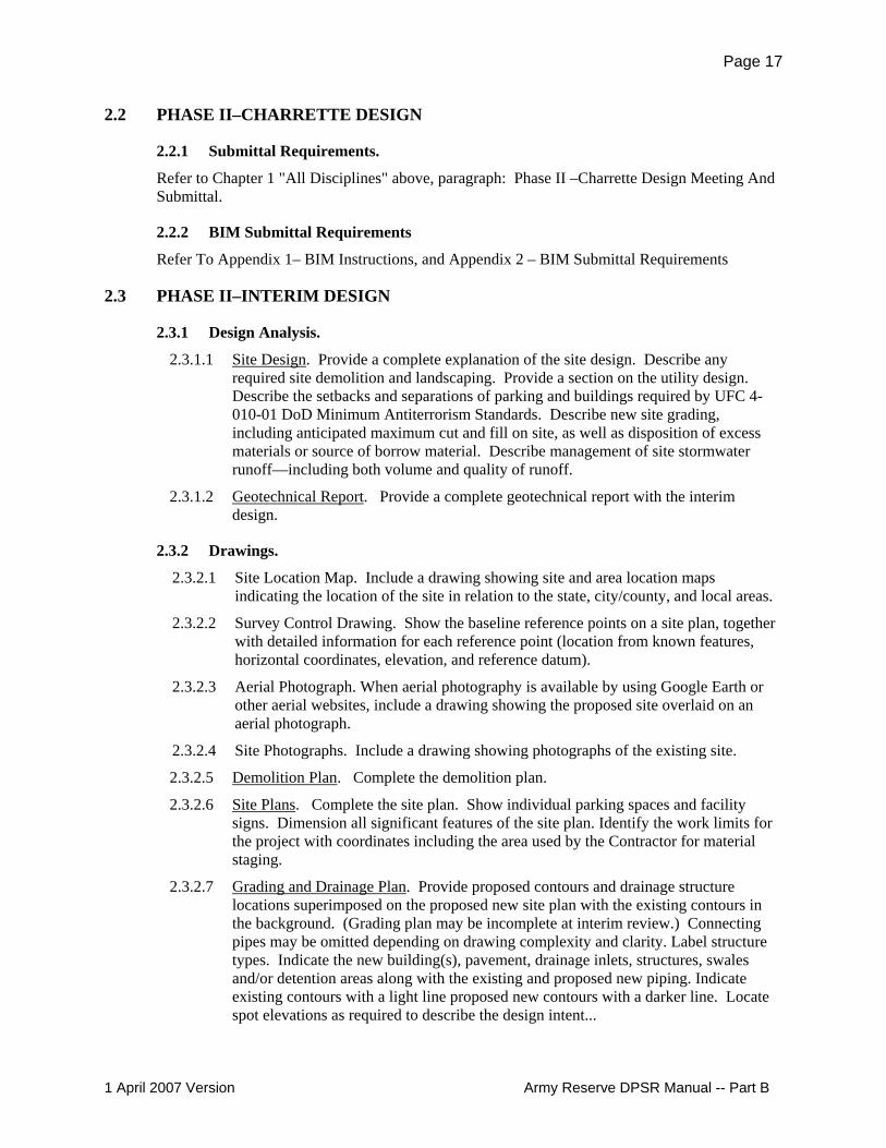
2.2 PHASE II–CHARRETTE DESIGN
2.2.1 Submittal Requirements.
Refer to Chapter 1 "All Disciplines" above, paragraph: Phase II –Charrette Design Meeting And Submittal.
2.2.2 BIM Submittal Requirements
Refer To Appendix 1– BIM Instructions, and Appendix 2 – BIM Submittal Requirements
2.3 PHASE II–INTERIM DESIGN
2.3.1 Design Analysis.
2.3.1.1 Site Design. Provide a complete explanation of the site design. Describe any required site demolition and landscaping. Provide a section on the utility design. Describe the setbacks and separations of parking and buildings required by UFC 4-010-01 DoD Minimum Antiterrorism Standards. Describe new site grading, including anticipated maximum cut and fill on site, as well as disposition of excess materials or source of borrow material. Describe management of site stormwater runoff—including both volume and quality of runoff.
2.3.1.2 Geotechnical Report. Provide a complete geotechnical report with the interim design.
2.3.2 Drawings.
2.3.2.1 Site Location Map. Include a drawing showing site and area location maps indicating the location of the site in relation to the state, city/county, and local areas.
2.3.2.2 Survey Control Drawing. Show the baseline reference points on a site plan, together with detailed information for each reference point (location from known features, horizontal coordinates, elevation, and reference datum).
2.3.2.3 Aerial Photograph. When aerial photography is available by using Google Earth or other aerial websites, include a drawing showing the proposed site overlaid on an aerial photograph.
2.3.2.4 Site Photographs. Include a drawing showing photographs of the existing site.
2.3.2.5 Demolition Plan. Complete the demolition plan.
2.3.2.6 Site Plans. Complete the site plan. Show individual parking spaces and facility signs. Dimension all significant features of the site plan. Identify the work limits for the project with coordinates including the area used by the Contractor for material staging.
2.3.2.7 Grading and Drainage Plan. Provide proposed contours and drainage structure locations superimposed on the proposed new site plan with the existing contours in the background. (Grading plan may be incomplete at interim review.) Connecting pipes may be omitted depending on drawing complexity and clarity. Label structure types. Indicate the new building(s), pavement, drainage inlets, structures, swales and/or detention areas along with the existing and proposed new piping. Indicate existing contours with a light line proposed new contours with a darker line. Locate spot elevations as required to describe the design intent...
1 April 2007 Version Army Reserve DPSR Manual -- Part B
Page 18
2.3.2.8 Storm and Sanitary Site Plan. Provide storm and sanitary sewer layouts superimposed on the proposed site plan. Label sewer structures. Pipe sizes and elevations may be estimated.
2.3.2.9 Utility Plans. Initiate the creation of the overall utility plan for other disciplines and coordinate this with other disciplines. Create utility plans for the sanitary sewer and create enlarged plans as required.
a. Facilities not in a military installation require coordination with the local utility and may involve separate submittals and permits.
b. Facilities in military installations that have some or all utilities privatized may involve separate submittals and compliance with the standards of that utility.
c. This sheet shall show the building and pavement locations with the connection of new utilities from the building to the existing utilities. Indicate the pipe sizes and/or capacities for electricity, gas, water and sewer. Indicate the adequacy of the water system for providing water for fire protection, including flow test data if available. Also indicate the above ground utility structures such as power poles and fire hydrants. Show estimated size for new project demand. Note: electrical may be on a separate Site Electrical Utility plan.
2.3.2.10 Road and Parking Area Profiles. Provide profiles of proposed roadway and parking lot facilities. Label vertical alignment, proposed profile grade, existing ground and utility crossings.
2.3.2.11 Typical Sections: Provide typical roadway and parking lot sections.
2.3.2.12 Boring Locations and Logs: Provide a drawing showing the location of the borings taken in the geotechnical investigation. Also provide boring logs that show graphically the types of soils encountered in the geotechnical investigation. Coordinate these sheets with the geotechnical engineer.
2.3.2.13 Right of Way Plans: If the project is located adjacent to private property, provide a separate “Right of Way” plan as required. Provide reference drawings showing all land required for construction of the project.
2.3.2.14 Other plans and information that may be useful: Survey Control/Reference Point Drawings, Aerial Photographs; Site Photos; Site Location Drawings.-
2.3.3 Specifications.
Provide a listing of specifications in the design analysis.
2.4 PHASE II–FINAL DESIGN
2.4.1 DESIGN ANALYSIS.
2.4.1.1 Site Design. Update and continue development of the design analysis submitted for the interim design, providing additional details as needed to describe the complete site design, including decisions made on the project. Provide information regarding site demolition and landscaping Provide a section on the utility design.
2.4.1.2 Geotechnical Report. Provide the geotechnical report.
2.4.2 Drawings.
Complete all the drawings required at the interim design review stage and incorporated approved comments. Add the drawings detailed below.
1 April 2007 Version Army Reserve DPSR Manual -- Part B
Page 19
2.4.2.1 Sanitary Sewer Profiles. Provide profile sections of the sanitary sewer system showing the manhole locations, pipe sizes and grades and other utility crossings.
2.4.2.2 Storm Sewer Profiles. Provide pipe profiles of the storm system when necessary showing manhole locations, pipe sizes and grades and other utility crossings.
2.4.2.3 Erosion Control Plan. Provide an erosion control plan with details that show the critical areas that are being protected while the project is under construction. Coordinate the details of this sheet with state and local authorities as required. Obtain the necessary permits such as NPDES, 401 and/or 404 and develop the Pollution Prevention Plan associated with NPDES.
a. Generally the A-E will coordinate the NPDES permit associated with construction activities, including obtaining forms and supporting data, but often the actual construction contractor obtains the permit and must abide by the terms of the permit.
b. The permit usually requires the signature of the "owner" of the facility and will require coordination with the local installation.
2.4.2.4 Details. Provide complete details of pavement joints, concrete, fences, manholes, catch basins, other site structures and any other details necessary to show all aspects of the design.
2.4.2.5 Exterior Facility Signage. Provide location of facility signage with complete design and installation details. This signage may be shown on the Site or Landscape drawings. A note referencing the signage schedule and any other facility signage information found in the architectural drawings will be included.
2.4.3 Specifications.
Provide a complete set of fully edited specifications from the listing given at the interim design.
1 April 2007 Version Army Reserve DPSR Manual -- Part B

Page 20
Chapter 3.0 – SITE MECHANICAL UTILITIES
3.1 GENERAL This chapter provides guidance for preparation and development for each of the different required submittal stages. Electrical utilities are found in the electrical chapter. Storm and other civil utilities are found in the civil chapter.
3.1.1 DESIGN CRITERIA
Refer to Chapter 1 "All Disciplines" above, paragraph: Reference Documents, and overall gen-eral requirements description.
3.2 PHASE II–CHARRETTE DESIGN
3.2.1 Submittal Requirements.
Refer to Chapter 1 "All Disciplines" above, paragraph: Phase II –Charrette Design Meeting And Submittal.
3.2.2 BIM Submittal Requirements
Refer To Appendix 1– BIM Instructions, and Appendix 2 – BIM Submittal Requirements
3.2.3 Site Utility Narrative
Provide information concerning sources and availability of gas, water, and fire utilities, and what is intended for the project.
Include a discussion of special plumbing and fire protection needs and requirements. Discuss up-grade issues when systems require larger capacities.
Discuss who owns the various utility systems, and what is involved in obtaining services.
3.3 PHASE II–INTERIM DESIGN
3.3.1 Design Analysis.
The charrette narrative forms the basis of the future design analysis. Depending on submittal re-quirements, include the following in narrative form:
3.3.1.1 List of Criteria. - Update the criteria listing in Chapter 1 to include design criteria, Codes and manuals used to create the design - design technical instructions or manuals, pamphlets, technical references, and other design guidance or criteria used in the design and their updates.
3.3.1.2 Known Utilities. Identify known Utilities, energy sources, locations, who manages/owns them, metering requirements, backflow prevention requirements, and alternatives.
3.3.1.3 Utility Alternatives. Provide life cycle cost analyses, as necessary or required, include narrative describing alternatives compared, reasons for choices selected, and calculations.
3.3.1.4 Fire Protection. Provide site fire protection system requirements.
1 April 2007 Version Army Reserve DPSR Manual -- Part B
Page 21
3.3.1.5 Other Requirements. Provide a list of items for which additional criteria, clarification, or guidance is required.
3.3.2 Drawings.
Provide plan views showing the features listed. Verify plan views of all utilities are coordinated with all other disciplines and properly interface with applicable building plans. Indicate locations and sizes of existing outside water and fire service lines, sanitary sewer lines, natural gas lines, and other utilities where required to support the project. Indicate fire department connection loca-tion for each building.
Show same scale as other site work drawings. Indicate proposed routing of new lines.
3.3.3 Specifications.
Provide a listing of specifications in the design analysis.
3.4 PHASE II–FINAL DESIGN
3.4.1 Design Analysis.
3.4.1.1 Update and continue development of the design analysis submitted for the interim design, providing additional details as needed to describe the complete site utilities design, including decisions made on the project.
3.4.1.2 Show applicable references for design assumptions.
3.4.2 Drawings.
3.4.2.1 Final plans are complete, solicitation ready, drawings with all necessary details, layout drawings, section views, plan views, and schedules.
3.4.2.2 Provide sections, elevations and details of sufficient scale to allow construction and installation of the work without additional design work by the construction contractor.
3.4.3 Specifications.
Provide a complete set of fully edited specifications from the listing given at the interim design.
1 April 2007 Version Army Reserve DPSR Manual -- Part B

Page 22
Chapter 4.0 – ARCHITECTURAL
4.1 GENERAL.
4.1.1 Scope.
This chapter presents aesthetic goals, design and construction criteria and other guidance for ar-chitectural design.
4.1.2 DESIGN CRITERIA
Refer to Chapter 1 "All Disciplines" above, paragraph: Reference Documents, and overall gen-eral requirements description.
4.1.3 Architectural Quality.
The architectural objective is to provide attractive structures using sound technical design knowl-edge that can be constructed using recognized, good industry practices in a cost effective manner. The design and construction must incorporate those characteristics which will provide structures that present continuing utility, durability and desirability, and which will be economical to main-tain for the life of the structure. The design must also provide a safe and healthy environment for occupants.
4.1.4 Military Installation Aesthetic Improvement Guidance.
The aesthetic quality of an area is not determined solely by the architecture of its buildings, the complexity of its development and landscape features nor by the predominate size, shapes, colors, and textures of adjacent forms. The aesthetic quality is determined by how all these elements function together and complement existing natural and man-made features. Typically not much criteria or guidance has been available concerning preservation or improvement of the aesthetic character of existing or new facilities and sites. This policy will provide an effective vehicle of communication between participating personnel to achieve harmony of design, and to assure a consensus of opinion in the approach to aesthetic quality.
4.1.4.1 Policy. The design agent is responsible for insuring that proper attention is paid to achieving an aesthetic design solution which includes harmony of design and the visual linkage of architecture to the surrounding community. The design must respect the architectural character of existing facilities that are to remain and be architecturally appropriate for the environment. Where the architecture of existing permanent facilities reflects a predominant character of style, design the new facilities to be in harmony with that character or style. The emphasis will also be placed on landscaping and structures other than buildings. Where applicable, review the Installation Design Guide before beginning any design effort and determine installation requirements. The installation DPW/Master Planner and ACSIM-AR must approve the buildings exterior appearance and material/color selections.
4.1.4.2 Application. The exterior appearance requirement applies to facilities having a significant visual impact within an Installation and/or occupancy which requires special design attention. The A-E will be notified when this requirement exists. Address the following items in each design:
1 April 2007 Version Army Reserve DPSR Manual -- Part B

Page 23
a. Insure all disciplines consider the effect of their decisions upon the project aesthetics.
b. Provide a descriptive narrative of the design approach used for each project. c. During the project definition or charrette design make a site visit to become
familiar with existing conditions and take color photographs of the surrounding area.
d. Give special attention to color and materials selection or relationship with existing surroundings.
e. Landscaping, exterior lighting, and signage will be given the same aesthetic consideration as the structures.
f. The exterior treatment of renovated buildings must be in harmony with the existing buildings. Important elements on the existing building that are compatible with the surrounding aesthetic quality of an area should be retained to the maximum extent possible.
g. Review site adapted building(s) with the same aesthetic criteria required for new design.
h. Provide physical screening for new exterior equipment, i.e., chillers, cooling towers, transformers, etc., to the maximum extent possible. However, note the requirements for full screening or maximum two-side screening in the Minimum Antiterrorism standards.
i. Providing underground electrical service lines.
4.1.5 Technical Requirements.
Materials and construction methods must comply with the instructional notes inserted within the applicable specifications.
4.1.6 Building Entrances.
Show all stoops, steps, or similar access features pertaining to the building entrance, that will normally be built by the building construction contractor as differentiated from sidewalks, drive-ways, etc., which are normally constructed by a site work contractor; on the architectural draw-ings.
4.1.7 Roof and Wall Insulation.
Indicate roof and wall insulation at a nominal thickness consistent with the insulation require-ments of the particular building or project. The insulation thickness and R-value should be indi-cated on the drawing.
4.1.8 Floor Drains and Slopes.
Show floor drains and shower heads on the architectural drawings as well as on the plumbing drawings and closely coordinate with other disciplines. All floors in areas requiring drains are to slope toward the drains. Coordinate floor drain locations with structural elements.
4.1.9 Designing for People with Disabilities.
Where the facilities are expected to be occupied by people with disabilities, the design is to be in accordance with The Americans with Disabilities Act Accessibility Guidelines (ADAAG) for Buildings and Facilities and the Uniform Federal Accessibility Standards (UFAS). **
** Revised ADA-ABA Guidelines. Note that at this writing (September 2006), there are planned
1 April 2007 Version Army Reserve DPSR Manual -- Part B

Page 24
new guidelines to replace the ADAAG and UFAS standards cited above. The new guidelines do not have the language that was in UFAS 4.1.4 (2)(b) excepting from the accessibility require-ments portions of certain Reserve and Guard facilities used by "able-bodied men", and this item remains unclear. Most federal agencies except DoD have adopted the new guidelines. DoD has not yet indicated when its adoption of new standards will take place. Updates may be found at http://www.access-board.gov/news/ada-aba.htm .
4.1.10 Arms Vaults.
Design arms vaults in conformance with AR 190-11. Review the checklist found in this docu-ment; verify that the requirements have been incorporated into the design.
4.1.11 Seismic Design; Overhead mounted Architectural Features.
Provide seismic design in accordance with requirements of the IBC.
Mount overhead architectural features items in accordance with the requirements of UFC 4-010-01 the paragraph on "Overhead Mounted Architectural Features".
4.2 PHASE II–CHARRETTE DESIGN
4.2.1 Submittal Requirements.
Refer to Chapter 1 "All Disciplines" above, paragraph: Phase II –Charrette Design Meeting And Submittal.
4.2.2 BIM Submittal Requirements
Refer To Appendix 1– BIM Instructions, and Appendix 2 – BIM Submittal Requirements
4.3 PHASE II–INTERIM DESIGN
4.3.1 Design Analysis.
Update the Charrette design analysis to include description of all design revisions and/or devel-opments. Provide interim DA as a new document, not as addenda to the Charrette document.
4.3.1.1 State the purpose, function, and capacities in sufficient detail to delineate and characterize functional features and the desired image or visual appearance of this project.
4.3.1.2 Describe the architecture of the existing facilities near the site and how the project relates to these facilities.
4.3.1.3 Include a Fire Protection/Life Safety analysis of the building occupancy classification, the type of construction and the occupancy group.
4.3.1.4 Provide a brief statement of the interior and exterior finish materials to be used in the project. Include an interior design statement that indicates the coordination of the structural finishes and features with the selected furnishings’ function, styling, detailing and finishes.
4.3.1.5 If the project has a kitchen, include kitchen equipment cut sheets (model number specific manufacturers’ product literature).
1 April 2007 Version Army Reserve DPSR Manual -- Part B
Page 25
4.3.2 Drawings.
Provide drawings in sufficient detail and annotated for the local user to visualize precisely how the architect has interpreted the using activity's functional and operational requirements. Provide as a minimum the following drawings:
4.3.2.1 Composite Floor Plan. If the main floor plans must be shown in segments in order to comply with the requirements of the proper scale, provide a smaller scale floor plan showing exterior wall, interior partitions, circulation elements, and cross referencing for enlarged floor plans and sections. Show overall dimensions on the floor plan and gross building areas tabulation on the drawing.
4.3.2.2 Floor Plans. Provide floor plans at 1/8"=1'-0" or ¼" = 1'-0" (1:100 or 1:50) scale. Show gross floor area tabulations if no composite sheet is included.
4.3.2.3 Building Elevations. Provide building elevations showing grading, openings, principal exterior materials and general profiles of the building (scale shall be the same as the floor plans).
4.3.2.4 Roof Plan. Provide a roof plan showing the roof configuration and methods by which rain is directed to the building perimeter.
4.3.2.5 Wall Sections. Provide typical wall sections (1/2" = 1'-0", or 1:20 minimum scale) that indicate major elements. Wall sections shall be unbroken where practical and indicate materials and floor-to-floor heights.
4.3.2.6 Provide drawings for: enlarged plans (stairs, lobby, and misc. plans), significant project details (roof, & elevator) wall types, door and window details, bathroom plans and details, vault plan and details (coordinated with structural).
4.3.2.7 Schedules. Provide a door schedule and room finish schedules indicating the materials and finishes used in the design. Also a special item schedule and/or notes shall be provided indicating any special items that will be required for the design.
4.3.2.8 Reflected Ceiling Plan. Provide a ceiling plan that indicates ceiling material and open ceiling areas. Indicate room numbers, light locations, registers, and all ceiling mounted items such as exit signs.
4.3.2.9 Fire Protection/Life Safety Plan. Provide fire protection/life safety drawings that indicate fire suppression information, exit signs, pull stations, exit devices, exit distance, emergency lights, detectors, alarm locations and fire panel locations. Summarize the code information from the design analysis on the drawings.
4.3.3 Specifications.
Provide a listing of specifications in the design analysis.
4.4 PHASE II–FINAL DESIGN
4.4.1 Design Analysis.
Update the Final design analysis from the interim design to include descriptions of all design re-visions and/or developments. Provide final DA as a new document, not as addenda to the Interim document.
4.4.2 Drawings.
Complete the final drawings to present a complete description of all the construction required and
1 April 2007 Version Army Reserve DPSR Manual -- Part B

Page 26
fully coordinate with other disciplines.
• Provide an interior and exterior signage plan, schedules and details indicating the color, location and types of signs used on the project. Include the location and mounting infor-mation for the interior and exterior Army Reserve Minuteman plaques.
• Landscape Plan. Most projects should include a modest landscape plan. If the landscape is extensive, the plan should be prepared by a registered landscape architect.
4.4.3 Specifications.
Provide a complete set of fully edited specifications from the listing given at the interim design.
1 April 2007 Version Army Reserve DPSR Manual -- Part B
Page 27
Chapter 5.0 –INTERIOR DESIGN
5.1 GENERAL. Refer to Chapter 1 "All Disciplines" above, paragraph: Reference Documents, and overall gen-eral requirements description.
5.1.1 Comprehensive Interior Design (CID).
A Comprehensive Interior Design (CID) package shall be included as a requirement in the A-E contract for all Army Reserve projects. The CID package includes the Furniture, Fixtures and Equipment (FF&E) design and the Structural Interior Design (SID). The two types of services cover different aspects of the interior environment. The FF&E includes selecting and developing interior building furnishings for an integrated visual design theme, which reflects the interior at-mosphere desired by the customer. The Structural Interior Design (SID) includes exterior fin-ishes, interior finishes, and special item selections; and is included as a separate binder submittal. Currently, there are four pre-established Army Reserve interior color schemes: Blue, Green, Rust, and Burgundy. The CID package must be developed concurrently with the design of the fa-cility and submitted for review.
The FF&E submittal includes:
a. FF&E Binder Index b. Statement of Design Objective c. Furniture Room Layouts d. Room Contents List e. Item Installation List f. Specification List by Tag g. Manufacturer POC List h. Furniture Illustration Sheets i. Furniture Procurement Sheets j. Presentation Color Boards k. Site Plan l. Architectural Floor Plans. m. Electrical/Data/Communications Plans n. Composite Furniture Floor Plans o. Enlarged Furniture Floor Plans p. Furniture Key Code Plan q. Enlarged Furniture Typical Details
The S.I.D. submittal includes:
r. SID Binder Index s. Statement of Design Objective t. Selection and sampling of all applied finishes including material, color, texture
and patterns necessary to complete the exterior and interior finishes and special items.
5.1.2 Furniture, Fixtures and Equipment (FF&E).
Furniture, Fixtures and Equipment (FF&E) includes selecting and developing interior building
1 April 2007 Version Army Reserve DPSR Manual -- Part B

Page 28
furnishings for an integrated visual design theme which reflects the interior atmosphere desired by the U.S. Army Reserve. This information shall be submitted in 3” D-ring binder(s), 8-1/2” x 11” format with only one foldout per page. The maximum foldout width shall be approximately 25”. Each binder shall be labeled on the outside spine and front cover with the following informa-tion: Project title and number, date, project location, design firm and type of submittal (Interim, Final, etc.). Material and finish samples shall indicate true pattern, color and texture, labeled with manufacturer, name, model number, and finish schedule tag reference. Each sample board is to be inserted into a clear, heavy-duty page protector that is sturdy enough to keep the pages from tearing out. The FF&E must be developed concurrently with the design of the facility. With each new submittal the Interior Designer of Record shall create new FF&E binder(s) to satisfy review comments until the Government approves the completed CID package. At the time of the furni-ture procurement (approximately six months prior to the Furniture BOD), the Interior Designer of Record is required to update the FF&E to correct any deficiencies, errors, or furniture product updates after the technical furniture review by Louisville District prior to the actual procurement of the furniture.
5.1.3 Structural Interior Design (SID)
The Structural Interior Design (SID) includes the selection and sampling of all applied finishes including material, color, texture and patterns necessary to complete the building’s interior archi-tectural features. Items include, but are not limited to: wall and floor finish materials, window and door finishes, glazing and trim materials, ceiling materials and finishes, millwork materials and finishes, paint and stain finishes, as well as specialty items. Since exterior colors, materials and finishes influence interior selections, include exterior materials as a separate section of the SID Items include, but are not limited to, roofing materials and finishes, gutter and downspout, soffit and fascia panels, brick and mortar, window and door frames, as well as specialty items. This information shall be submitted in 3” D-ring binder(s), 8-1/2” x 11” format with only one foldout per page. The maximum foldout width shall be approximately 25”. Each binder shall be labeled on the outside spine and front cover with the following information: Project title and number, date, project location, design firm and type of submittal (Interim, Final, etc.). Material and finish samples shall indicate true pattern, color and texture, labeled with manufacturer, name, model number, and finish schedule tag reference. Each sample board is to be inserted into a clear, heavy-duty page protector that is sturdy enough to keep the pages from tearing out. The SID must be developed concurrently with the design of the facility. With each new submittal the Interior Designer of Record shall create new SID binder(s) to satisfy review comments until the Government approves the completed SID package.
5.2 PHASE II–CHARRETTE DESIGN
5.2.1 Submittal Requirements.
Refer to Chapter 1 "All Disciplines" above, paragraph: Phase II –Charrette Design Meeting And Submittal.
5.2.2 BIM Submittal Requirements.
Refer To Appendix 1– BIM Instructions, and Appendix 2 – BIM Submittal Requirements
5.3 PHASE II–INTERIM DESIGN The interim submittal shall include the design analysis, construction drawings and CID package consisting of the FF&E and SID material and finish samples.
1 April 2007 Version Army Reserve DPSR Manual -- Part B

Page 29
5.3.1 Design Analysis.
5.3.1.1 Statement of Design Objective. Provide a narrative explaining the interior design concept of the facility. Where applicable, include desired psychological impact of the interior environment on its inhabitants and proposed method of accomplishing same by using space planning, shapes, forms, color, patterns, textures, fabrics and furnishings. Include which of the four Army Reserve color schemes was the starting point for the project. Explanations of unusual conditions shall be included, such as the coordination of special laminates and fabrics between various product lines and manufacturers to provide a consistent overall environment. Explanations of deviations or unusual conditions required by the Army Reserve Unit of the furnishings layout and/or items used from the information included in UFC 4-171-05, shall also be included.
5.3.1.2 Specification Listing. Provide a listing of specifications in the design analysis.
5.3.2 Drawings.
5.3.2.1 Furniture Floor Plans. Provide as part of the construction drawings, furniture floor plans showing the furnishings required for the various functions that are to be housed in the facility, indicating the adequacy of the size and shape of each space and the spatial relationship between the furnishings and doors, windows, light switches, thermostats, electrical/communication connections/outlets, bulletin boards, projection screens and other building features. Basic furniture plans shall be provided as a minimum with any additional furnishings items known at this stage of design included. Any areas that may pose “furniture fit” or other problems should be highlighted or annotated by notes on the furniture drawings to ensure that they are addressed at the interim review meeting. Drawings shall include Composite Furniture Floor Plans, Systems Furniture Plans, and Systems Furniture Panel Plans (if systems furniture is included in the project). Other plans shall be provided as the project requires i.e., Systems Furniture Component Plans for complex panel systems projects. Furniture Floor Plans shall include the room names and numbers. If the furnishings and room names and numbers overlap each other on the drawings, the room names and numbers should be relocated to provide legible information. Furnishings are to be “Government Furnished, Government Installed” (GFGI). Include a statement to the furniture drawings indicating that the furniture drawings are for information only, are to be used to coordinate furnishings locations with other disciplines, and that the furnishings are not part of the construction contract.
5.3.2.2 Additional Plans, Enlarged Plans, Elevations and Details. Provide as necessary any plans, enlarged plans, elevations and details indicating location and identification of accent walls, graphics, wall hangings, wall patterns/finishes, floor patterns/finishes, wall and corner protection and special items known at this stage of design.
5.3.2.3 Exterior and Interior Color, and Special Item Schedules. Provide an Exterior Color Schedule, an Interior Color Schedule, a Special Item Schedule (or notes) for those items known at this stage of design. These finishes include, but are not limited to, exterior and interior wall finish materials, window and door frames, doors, glazing, roofing materials, trim materials, floor and ceiling finishes, signage colors and styles, casegoods, toilet partitions, lockers and other visible materials affecting visual design aesthetics. Include a general non-proprietary disclaimer to indicate that naming the commercial product does not restrict the construction contractor to the particular product identified. (Example: “Manufacturers referenced are intended to establish
1 April 2007 Version Army Reserve DPSR Manual -- Part B

Page 30
color and finish only, and are not intended to limit selections from other manufacturers. When alternate selections are submitted, submittal shall include materials listed for comparison.”) Each finish/item selected must be available from at least three manufacturers. (Exceptions to this must be discussed with Louisville District on a case by case basis with detailed explanations provided.)
5.3.3 FF&E and SID.
5.3.3.1 Finish Samples and Furnishing Illustrations. The finish samples for the FF&E and SID may be presented loose at the interim review meeting or mounted on color boards as part of the FF&E and SID binder(s). If presented loose, each sample shall be labeled with the following information: manufacturer, finish model number and/or color number, where the finish is used, fabric content, finish schedule tag reference and any other pertinent information. If mounted on color boards as part of the FF&E and SID binder(s), a Finish/Special Item Key shall be included indicating the following information: manufacturer, finish model number and/or color number, where the finish is used, fabric content, finish schedule tag reference and any other pertinent information. Illustrations of the major furnishing products or product lines may be presented at the interim review meeting using manufacturers’ product catalogs and pamphlets or included in the FF&E binder.
5.3.3.2 Typical Furniture Layouts. Provide the “basic” typical room furniture layouts and typical workstations used in the project. It is not expected that every typical, every atypical and every workstation will be known at this stage of the design. The typicals included are to be representative only. Include the furniture “tags” in these typicals and the general project information. Drawings must be legible with a minimum drawing scale of 1/4" = 1' - 0". The typicals will include basic information on where they are used, such as “Full Time Private Offices”, “Unit Exclusive Shared Offices”, etc. They may also include the room numbers where the typicals are to be used. These tagged typicals may also be shown on the construction drawings as described in the final submittal paragraph.
5.3.3.3 Room Contents List. This report shall provide the furnishings specified for each room by furniture tag, description, manufacturer, model number and quantity. List all desk units and panel systems workstations by a group furniture tag. Desk units consist of the desk, credenza, bridge, overhead, etc. and are tagged as one unit. The report is to be sorted by building, floor, room and tag in alpha/numeric order and shall be submitted in the Government required ARMY RESERVE Comprehensive Interior Design Furniture Access Program.
5.4 PHASE II–FINAL DESIGN
5.4.1 Design Analysis.
The submittal shall have the interim submittal design analysis updated to include all design revi-sions and/or developments.
5.4.2 Drawings.
Update and complete all information provided in previous submittals and approved review com-ments.
5.4.2.1 Furniture Floor Plans. Provide as part of the construction drawings Composite Furniture Floor Plans, Systems Furniture Plans, Systems Furniture Panel Plans and
1 April 2007 Version Army Reserve DPSR Manual -- Part B

Page 31
Enlarged Furniture Floor Plans. Other plans shall be provided as the project requires i.e., Systems Furniture Component Plans for complex panel systems projects. Plans shall reflect added or changed items since the previous submittal. Furniture Floor Plans will consist of the following:
a. Composite Furniture Floor Plans. For large facilities include room names and numbers but do not include furniture tags. Include a building footprint key plan in the lower right hand corner of the sheet indicating how the floor plan has been divided between the larger scaled sheets. For smaller facilities where the architectural floor plan does not require multiple plan drawings, the Composite Furniture Floor Plan shall include room names and numbers, and furniture tags but does not require a building footprint key since the facility is not split between two or more sheets. All furniture plans are to be labeled REFERENCE ONLY or NOT IN CONTRACT (NIC).
b. Enlarged Furniture Floor Plans and Enlarged Furniture Typical Details are to include all furniture, desk unit and panel systems workstation/panel tags, furniture legend representing the furniture tag with description, and building key plan in the lower right hand corner of the sheet indicating how the floor plan has been divided between the larger scaled sheets. 1) Systems Furniture Panel Plan(s) are to include dimensions for placement
within a room for accurate installation of the panel systems furniture and all walls, doors and window locations. Drawing scale must be large enough scale so that the furniture “footprints” are clearly discernible and data is legible.
2) Furniture tags --Every furniture item, desk unit and panel systems furniture workstation is to be tagged individually with alpha/numeric tags. The desk unit, consisting of the main desk components; i.e. desk, credenza, bridge, overheads, keyboard, etc. will be tagged as one unit D1, D2, D3, etc. All panel systems furniture workstations will be tagged as WS1, WS2, WS3, etc. with the panel systems pods only tagged as a P1, P2, P3, etc.
3) Include enlarged views of each metal desk-based unit typical and each panel systems furniture workstation typical indicating all components.
4) The enlarged Furniture Panel Systems only plan should be tagged listing all panels with sizes, powered and non-powered, power end feed locations, and duplex/data locations.
5) All furniture plans are to be labeled REFERENCE ONLY or NOT IN CONTRACT (NIC).
c. Structural related built in equipment (such as marker boards, projection screen and map rails) or cabinets (items to be provided with the construction contract) shall be shown and identified on the furniture plans as well as on the architectural plans, and on any enlarged plans of those areas where such items are placed in the facility. These items shall be shown and identified by name and/or SID finish or Special Item code.
5.4.2.2 Additional Plans, Enlarged Plans, Elevations and Details. Provide as necessary any plans, enlarged plans, elevations and details indicating location and identification of accent walls, graphics, wall patterns/finishes, floor patterns/finishes, wall and corner protection and special feature items.
5.4.2.3 Electrical/Data/Communication Plans. Provide as necessary electrical/data floor box and wall power feed locations with dimensions to coordinate with the panel systems furniture layouts for all areas that are to receive floor box and wall locations.
1 April 2007 Version Army Reserve DPSR Manual -- Part B

Page 32
5.4.3 Specifications.
Provide all specifications, fully edited, necessary to accurately and completely describe/identify the complete project.
5.4.4 FF&E and SID Binders.
Separate FF&E and SID binders are included at final design to illustrate the designer’s intended interior and exterior color schemes, material finishes, colors for the furnishings, and detailed fur-nishing layouts. The FF&E contains the furnishings procurement and installation information needed to purchase and install the furnishings that are usually procured under a separate contract and are provided with the construction documents for information only. Furnishings presentation color boards are also included in the FF&E binder. The presentation color boards and Fin-ish/Special Item Key for the structural finishes are included in the SID binder. Maximum binder thickness shall be four inches. Binders shall indicate project information on the cover and on the spine for easy identification. (See General Interior Design paragraph.) The FF&E and SID bind-ers shall include the following as a minimum.
5.4.4.1 FF&E Binder with Presentation Color Boards. Provide the following in the FF&E binder:
a. Index. Provide an index for the FF&E binder. b. Statement of Design Objective. Provide the narrative included in the design
analysis explaining the interior design concept of the facility. Edit/expand the previous submittal narrative as needed to convey the design intent as it relates to FF&E and the structural finishes.
c. Furniture Room Layouts. Provide individual room floor plans representing the furniture layouts for all rooms that are to receive furniture. Include the furniture “tags” with descriptions on these sheets and include all architectural elements located within the room. Drawings must be legible with a minimum drawing scale of 1/4" = 1' - 0". Indicate room name and number, and the general project information on each sheet. Like room layouts may be listed on one individual room sheet with all rooms to receive the same furniture layout listed. Include one copy of the furniture legend in the section with the room layouts.
d. Room Contents List. This document shall provide the furnishings specified for each room by furniture tag, description, manufacturer, model number and quantity. List all desk units and panel systems furniture pods by a group furniture tag. Do not list individual components and panel systems furniture parts required to build the units. The report is to be sorted by building, floor, room and tag in alpha/numeric order and shall be submitted in The ARMY RESERVE Comprehensive Interior Design (CID) Furniture Access required government program.
e. Item Installation List. This document provides the location by room for each item included in the furniture package. List all desk units and panel systems furniture pods by a group furniture tag. Do not list individual components and panel systems furniture parts required to build the units. The report is to be sorted by furniture tag, description, manufacturer, model number, room number and quantity listed in alpha/numeric order by the furniture tag and shall be submitted in the ARMY RESERVE Comprehensive Interior Design (CID) Furniture Access required government program.
f. Specification List by Tag. This document is to define the furniture requirements for the project. It shall list all pertinent information for each furniture item specified in the furniture package including the tag, description, manufacturer,
1 April 2007 Version Army Reserve DPSR Manual -- Part B
Page 33
g. Manufacturer POC List. This document is to list the furniture manufacturers specified for the project with address, telephone, fax, and e-mail address: Contact’s name, address, telephone, fax, and e-mail address. POC List shall be submitted in the ARMY RESERVE Comprehensive Interior Design (CID) Furniture Access required government program.
h. Furniture Illustration Sheets. Provide furniture illustration sheets for all products specified in the furniture package. Illustrations are to be represented by black and white or color photographs. Information on the furniture illustration sheets shall include furniture tag, description, model number, finishes, size and manufacturer. A product photo or brochure of the desk units and panel systems workstations may be included or .jpg or .bmp file format photos may be used. It is not necessary to include individual photos of the parts and pieces that make up the desk units and panel systems furniture workstations. The Furniture Illustration Sheets shall be submitted in the ARMY RESERVE Comprehensive Interior Design (CID) Furniture Access required government program.
i. Furniture Procurement Sheets. Provide an individual furniture procurement sheet for each manufacturer specified in the furniture package. Information on these sheets shall include manufacturer’s name, address, telephone, fax and e-mail address; Contractor’s name, address, telephone, fax and email address; Contact’s name address, telephone, fax and e-mail address. List GSA Contract number and contract expiration date if applicable. List Open Market if product in not on a GSA Contract. The Furniture Procurement Sheets shall be submitted in the ARMY RESERVE Comprehensive Interior Design (CID) Furniture Access required government program.
j. Presentation Color Boards. Provide presentation color boards in an 8 ½” x 11” binder format. The presentation color boards shall depict all materials and finishes for each proposed furniture item. Label the material and finish sample with specific color names with references to the specified furniture tag. The material and color samples provided must be large enough to indicate true patterns, colors and textures. Each sample board is to be inserted into a heavy-duty clear page protector that is sturdy enough to keep the pages from tearing out. COLORED COPIES OF FINISHES ARE NOT ACCEPTABLE.
k. Drawing Set Plans. Provide full-size plots with the FF&E binder of the following: 1) Site Plan – A Site plan and vicinity map shall be provided showing the
location of the building or buildings in which the subject furniture is to be installed and site conditions/restrictions as provided in the construction contract.
2) Architectural Floor Plans – Architectural floor plans shall be provided showing relationships and dimensions of all areas receiving furniture. Include the locations of any special items i.e., trophy cases, projection screens, marker boards, building directories and map rails as provided in the construction contract.
3) Electrical/Data/Communications Plans – Plans shall be provided showing electrical receptacles, power feeds, switches, thermostats, fire alarm annunciators, telephone, and computer locations for areas receiving furniture.
1 April 2007 Version Army Reserve DPSR Manual -- Part B
Page 34
Place all dimensions for floor boxes on the electrical/data/communications plans as provided in the construction contract. This would include all floor junction boxes for panel power feeds and any floor boxes located in classrooms, conference rooms, training center rooms, etc.
4) Composite Furniture Floor Plans – Include composite furniture floor plans as described in paragraph "Drawings" above.
5) Enlarged Furniture Floor Plans – Include enlarged furniture floor plans as described in paragraph "Drawings" above.
6) Enlarged Furniture Typical Details – Include enlarged furniture typical plans described in paragraph "Drawings" above.
7) Furniture Key Code Plan – Provide a key code plan per manufacturer’s key code requirements listing all furniture to be keyed alike and random.
5.4.4.2 SID Binder with Presentation Color Boards. Provide the following in the SID binder:
a. Index. Provide an index for the SID binder b. Statement of Design Objectives. Provide the narrative included in the design
analysis explaining the interior design concept of the facility. Edit/expand the previous narrative submittal as needed to convey the design intent as it relates to the structural finishes.
c. SID Presentation Color Boards. Provide in the SID binder presentation color boards. Code and coordinate samples with the exterior finish, interior finish and special items schedules in the project contract documents. Provide a Finish/Special Item Key or legend that includes what each sample is used for, the manufacturer, style name and/or number, pattern name and/or number, color name and/or number, finish schedule tag reference, and any remarks or notes needed to describe what the boards are illustrating. Samples shall be large enough to show full patterns, colors, and textures. Securely mount samples to the presentation boards to withstand long periods of use. PHOTOGRAPHS OR COLOR XEROX COPIES OF FINISHES, MATERIALS AND COLORS ARE NOT ACCEPTABLE. Materials and finish shall be mounted on presentation boards in an 8 ½" x 11" binder format and inserted into a clear, heavy-duty page protector that is sturdy enough to keep the pages from tearing out of the binder.
1 April 2007 Version Army Reserve DPSR Manual -- Part B

Page 35
Chapter 6.0 – STRUCTURAL
6.1 GENERAL. This chapter states the minimum structural design requirements for each of the contract submittal stages.
6.1.1 DESIGN CRITERIA
Refer to Chapter 1 "All Disciplines" above, paragraph: Reference Documents, and overall gen-eral requirements description.
6.2 PHASE II–CHARRETTE DESIGN No structural submittal requirements. However, the structural engineer must have strong input in the creation of the column and roof plan, which is carried out by the architectural discipline. The reason for this input is so the structural engineer insures that the column grid lines and/or bearing wall locations are such that an adequate framing plan can be achieved.
6.3 PHASE II–INTERIM DESIGN The structural portion of the interim design submittal must outline for approval the proposed methods and materials of design and construction. Include the following:
6.3.1 Design Analysis.
6.3.1.1 General. Provide a general description of the scope of the project and all the major structures. Give overall building dimension and a description of the principal features such as wall and roof construction. If the building is irregularly shaped, explain where seismic joints will be placed to create regular shapes or provide a statement that dynamic analysis of the building will be performed (Note: Seismic joints are preferred in areas of high seismic activity for all structures of an irregular shape. For buildings in areas of low seismic activity, building joints are recommended only as needed for expansion and contraction purposes.)
6.3.1.2 Criteria. Include a listing of the required technical manuals, building codes and specifications in the design analysis.
6.3.1.3 Framing System.
a. Provide a brief structural narrative on the gravity load resisting framing system chosen and the reasons why.
b. Provide a brief narrative on the lateral load resisting system and how these loads will be transmitted to the foundations.
6.3.1.4 Foundation. Give a brief description of the anticipated foundation type/system based on the geotechnical report. Reference the geotechnical report to state the allowable soil bearing capacity, modulus of subgrade reaction, minimum footing sizes, and minimum frost depth requirements. The designer may also refer to similar construction in the area if it is known and if it adds value to the submittal.
6.3.1.5 Special. List special/unique design features.
1 April 2007 Version Army Reserve DPSR Manual -- Part B
Page 36
6.3.1.6 Information Needed to Complete the Design. List any unknowns that the designer needs to complete the design. For instance, the designer may request from the user a list of the military vehicles and their weights for the purpose of designing slabs.
6.3.1.7 Calculations. The following specific items shall be included to the extent they are complete:
a. Load Assumptions. State the dead and live loads to be designed for, including roof and floor loads. Calculate the wind loads, snow loads, lateral earth pressure loads, and seismic loads.
b. Calculate both positive and negative wind pressure with the controlling pressures summarized in tabular form. Include the following wind pressures as a minimum: wind on frame, wall, wall corners, roof, roof ridges, eaves, and roof corners.
c. Calculate the basic seismic loading for the frame or lateral load resisting system and contrast them with the comparable wind loads. Note the controlling design loads. Detailed calculations for seismic loads on parts and portions are not required at this submittal level.
d. Material Stresses. Describe the value to be used for the allowable or working stresses of the principal structural materials. State the design stress values for the materials of construction.
e. Furnish all other necessary preliminary calculations for typical roof, floor, and foundation members as applicable for the structural system proposed.
6.3.2 Drawings.
Furnish sufficient plans for foundations, and framing plans for roof and floors, as applicable, to indicate layout of principal members. Typical sections should be furnished through roof, floor, and foundation indicating materials and type of construction proposed. The architectural wall sections may satisfy this requirement. Furnish a plan identifying the location of all seismic joints.
6.3.3 Specifications.
Provide a listing of specifications in the design analysis.
6.4 PHASE II–FINAL DESIGN
6.4.1 Design Analysis.
Furnish complete checked calculations for all structural members. Incorporate any changes re-quired by comments on interim submittal.
6.4.2 Drawings.
Furnish complete final plans and details of all structural elements. Before this submittal, coordi-nate structural drawings with all other design disciplines. Always include the items listed below on the final drawings if applicable:
a. A general structural notes sheet indicating design criteria and material requirements. Include criteria on wind, snow, seismic and foundation requirements. List the material requirements for masonry, concrete and steel.
b. Roof framing plan and details including details of any opening in the roof. c. Intermediate floor framing plans and stair details on multiple story structures. d. Loads, spans and support reactions of features to be construction contractor
designed (e.g., connector plates on wood trusses that are construction contractor
1 April 2007 Version Army Reserve DPSR Manual -- Part B
Page 37
designed based on member stress information shown by the Engineer on the structural drawings).
e. Column schedule, beam schedules, and connection schedules. f. Foundation plan including any notes relative to special foundation treatment
required and cross-references to proper specification sections. g. Foundation section and details. h. Layout of expansion, construction, and contraction joints in floor slabs;
horizontal and vertical joints in foundation walls; joints in footing; and layout of control joints in masonry walls.
i. Typical and special sections as required. j. Details of expansion, construction, and contraction joints in concrete. k. Layout and detail of exterior entrance pads and steps. l. Lintel plan(s) and schedules. m. Masonry wall elevations as required. n. Details of any special items. o. General and special notes as required.
6.4.3 Specifications.
Provide a complete set of fully edited specifications from the listing given at the interim design.
1 April 2007 Version Army Reserve DPSR Manual -- Part B

Page 38
Chapter 7.0 – MECHANICAL – HVAC, PLUMBING, AND FIRE PROTECTION
7.1 GENERAL This chapter provides guidance for preparation and development for each of the different required submittal stages.
7.1.1 Design Criteria
Refer to Chapter 1 "All Disciplines" above, paragraph: Reference Documents, and overall gen-eral requirements description.
7.1.2 Seismic Design for Mechanical Equipment
Provide seismic design in accordance with requirements of the IBC.
7.1.3 Overhead mounted Mechanical Equipment.
Mount overhead mechanical items in accordance with the requirements of UFC 4-010-01, the paragraph on "Equipment Bracing".
7.2 PHASE II–CHARRETTE DESIGN
7.2.1 Submittal Requirements.
Refer to Chapter 1 "All Disciplines" above, paragraph: Phase II –Charrette Design Meeting And Submittal.
7.2.2 BIM Submittal Requirements
Refer To Appendix 1– BIM Instructions, and Appendix 2 – BIM Submittal Requirements
7.2.3 HVAC.
7.2.3.1 Discuss with the user and Project Engineer/ Architect the known and allowable HVAC alternatives and requirements. Include the alternatives in the narrative.
7.2.3.2 Discuss base requirements to communicate with a base-wide EMCS
7.2.4 Site Utilities.
Refer to Chapter "Site Mechanical Utilities".
7.2.5 Plumbing.
Include a discussion of special plumbing needs and requirements.
7.2.6 Fire Protection
7.2.6.1 Discuss with the Fire Department or base any special requirement the local fire department may have such as a fire department connection type.
1 April 2007 Version Army Reserve DPSR Manual -- Part B

Page 39
7.2.6.2 Obtain fire flow data relevant to the site at the earliest practicable time. (Note that UFC 3 600 01 paragraph 4-1.3 requires the designer to perform or witness a flow test on hydrants near site not just receive fire flow data from others.)
7.2.7 Special Considerations.
These items are found in the Appendix 1 of the 1391.
7.3 PHASE II–INTERIM DESIGN
7.3.1 Design Analysis.
The charrette narrative forms the basis of the future design analysis. Depending on submittal re-quirements, include the following in narrative form:
7.3.1.1 Heating, Ventilating and Air-Conditioning (HVAC).
a. List of Criteria - Codes and manuals used to create the design - design technical instructions or manuals, pamphlets, technical references, and other design guidance or criteria used in the design and their updates.
b. Design conditions used in calculations – inside and outside temperatures, personnel load, equipment heat release (if any), energy sources, outside air or ventilation requirements, U-factors, and other special conditions.
c. Include discussion and calculations for Special Considerations, when required, in the Analysis.
d. Detailed system heating and cooling load calculations. Use Corps of Engineers approved electronic calculation software.
e. Provide narrative descriptions of the systems considered, justification for selection, intended equipment, description of air distribution, zoning, HVAC controls description, and description for any connections to existing systems.
f. Describe the various equipment items. g. Describe the piping systems. h. When specifically required, provide Energy Monitoring and Control System
(EMCS) or Utility Monitoring and Control Systems (UMCS) requirements narrative identifying existing EMCS/UMCS conditions, and requirements for providing new or future interface EMCS/UMCS on this project.
i. Provide a list of items for which any additional criteria, clarification, or guidance is required by the designer to complete the design.
j. Describe major items that deviate from the Reserve Design Guide standards.
7.3.1.2 Plumbing.
a. Criteria listing - manuals, applicable codes and standards, etc. b. Plumbing calculations as necessary to determine number of fixture units, cold
and hot water capacity requirements, and equipment or capacities of miscellaneous and special systems indicate male and female building populations.
c. Fixture determination listing quantity and type of fixtures and other fixtures such as drinking water fountains, service sinks, kitchen equipment, and vehicle wash equipment, etc.
d. Description of domestic water heating and storage equipment, including capacity, type (gas, electric, boiler, water), materials, and insulation.
e. Include a brief description of miscellaneous systems such as compressed air (capacity, pressure, piping, location of air outlets, etc.), roof drainage, natural gas
1 April 2007 Version Army Reserve DPSR Manual -- Part B

Page 40
(pressure, quantity, and equipment served), vehicle exhaust, and other special systems.
f. Include a brief description of whether a radon system is required, and radon system planned,
g. Provide a list of items for which additional criteria, clarification, or guidance is required.
h. Describe major items that deviate from the Reserve Design Guide standards. i. List of information required to complete the design.
7.3.1.3 Fire Detection and Suppression System.
a. List of Applicable Criteria - NFPA, UFC 3-600-01, and other applicable governing criteria.
b. Listing of the hazard classifications for each space and discussion of protection requirements for specific hazards.
c. Discussion of fire protection features for each building to reflect the types of systems considered with a description of the systems selected.
d. Provide a detailed description of the fire suppression system and its controls such as activation of the system, interlocks with the HVAC system, and connection to detection and alarm systems. Describe the fire detection and alarm system features that are used to actuate the suppression systems.
e. If water sprinkler systems are required, provide preliminary hydraulic calculations for the most hydraulically demanding area to insure the flow and pressure requirements are met with current water supply. Provide results of flow test data with preliminary hydraulic calculations. Make recommendations about the plumbing requirements, the sprinkler system requirements, and backflow.
f. Identify the requirements for fire pumps and storage tanks based on preliminary calculations.
g. Describe major items that deviate from the Reserve Design Guide standards.
7.3.2 Drawings.
Provide plan views showing the features listed.
7.3.2.1 Heating, Ventilating, and Air Conditioning (HVAC). Include heating, ventilating, and air-conditioning equipment layouts and include locations of major pieces of equipment. Include the air distribution duct layouts for supply, return, ventilation and exhaust ducts (single line duct layouts are permissible at this phase), hoods, and other items of major equipment required for the facility. Include major pieces of equipment listed. Provide schedules filled out with what is known; schedules are not required to be completed.
7.3.2.2 Plumbing. Plumbing fixture layout, floor and area drains, and plumbing equipment layouts (hot water generator, storage tanks, air compressors, etc.).
7.3.2.3 Outside Utilities. (See Chapter: Site Mechanical Utilities)
7.3.2.4 Fire Suppression System. Prepare a plan for each floor of each building. Provide the following types of information:
a. Indicate all building areas, their sprinkler hazard classification, and extent of fire protection.
b. Provide the location of any major fire suppression equipment or features such as, fire service line location, sprinkler risers, standpipes, inspector test and drain, fire department connections, pump, etc.
1 April 2007 Version Army Reserve DPSR Manual -- Part B
Page 41
c. Provide the location and hazard of any special fire suppression systems such as in-rack sprinkler systems, deluge systems, and hose racks.
7.3.3 Specifications.
Provide a listing of mechanical and plumbing specifications in the design analysis.
7.4 PHASE II–FINAL DESIGN
7.4.1 Design Analysis.
7.4.1.1 General. The final design analysis is a refinement of the prior design analysis and contains all the information called for in those sections of this chapter. Include required and missing information that was not included in prior submittal phases.
7.4.1.2 HVAC Equipment. Provide equipment sizing calculations with summaries of all major items of mechanical equipment such as air handling units and coils, condensing units, water chillers, boilers, pumps, humidifiers, cooling towers, fans, water heaters and tanks. For all computer-generated calculations (cooling loads, heating loads, pipe sizing, duct sizing, etc.), the design analysis shall contain layout sketches that show how the building or system was segmented for computer input. Show manufacturers’ make and model number of equipment used for design purposes, and show weights of major items of equipment. Provide vendor information for equipment selected and mark the specific items on the vendor’s literature.
a. Cut sheets, product selections forming the basis of design: Clearly mark the selected product type or model intended to apply to the project. If the cut sheets or brochures are standard printouts from manufacturer showing several variations, either mark/mark out to indicate just the selected product or accompany the cut sheet with a cover sheet or narrative showing the applicable product
7.4.1.3 Piping. Include all mechanical pipe-sizing computations in the analysis. Show design flow, pipe size, friction factors, slopes, lengths, and elevations (where applicable), quantity conducted, and velocity in the various mains and branches. Where necessary, include flow diagrams in the analysis.
7.4.1.4 Ducting. Show all duct sizing computations in the analysis. Show friction loss and clearly indicate the air velocities encountered in the main ducts. Where necessary, include flow diagrams in the analysis. Provide static pressure on fans and air handling units based upon complete takeoff of static losses. Include filter losses.
7.4.1.5 Sprinklers. For fire sprinkler system information, include hazard classification, zoning (if appropriate), and sizes of all riser pipes including wet and dry pipes, sprinkler valves, mains, and principle branches based on available water pressures by either computer-generated hydraulic analysis, or manual calculations. Provide the results of the analysis for a fire pump. When a fire pump is required, provide vendor information on the pump. Provide computations for other applicable systems such as standpipe, deluge, or in-rack sprinkler systems.
7.4.2 Drawings.
7.4.2.1 General. Final drawings are complete and solicitation ready when all necessary details, layout drawings, section views, plan views, and schedules are finished and include the incorporation of all review comments and resolutions.
1 April 2007 Version Army Reserve DPSR Manual -- Part B

Page 42
7.4.2.2 Sections and Elevations. Show sufficient sections and elevations to indicate clearly the exact location of the particular item in relation to other building or equipment items. Sections shall indicate critical interference between mechanical items and building features.
7.4.2.3 Details. Provide sufficient elevations and details to allow construction and installation of the work without additional design work by the construction contractor.
7.4.2.4 Accessories. Where equipment connection details are shown, indicate all required valves, gages, and fittings required and minimum sizes. Coordinate with specification requirements and make sure valves, fittings, etc., that are specified are included in the detail furnished with each piece of equipment.
7.4.2.5 Mechanical Room Plans. Include an enlarged plan of the mechanical room(s) indicating all equipment with, as a minimum, the manufacturer’s recommended maintenance clearances between each item. Indicate adequate spacing for HVAC controls, electrical panels and other similar items. Indicate space required for placement of all such items as coils, filters, heat exchanger tubing, motors and belts on the plan. Show routing of hydronic piping, location of sprinkler riser, and location of plumbing items such as water heaters and air-compressors.
7.4.2.6 Sizes. Final plans must show all pipe and duct sizes. Draw ductwork to scale on plans. Provide details of catwalks, ladders, platforms, access panels, and doors necessary for operation and maintenance of equipment, valves, and accessories. Show all locations of turning vanes, and all volume, fire and smoke dampers.
7.4.2.7 Performance Characteristics. Place performance characteristics for all items of mechanical equipment in the equipment schedules. Do not make selections that would restrict to any one manufacturer the typical equipment characteristics selected. The equipment specified must be able to be submitted on by at least 3 manufacturers as a minimum for ordinary equipment.
7.4.2.8 Schedules. Verify that all schedules reflect the necessary equipment information so that the contractor can select all of the equipment without referring to a specific model/manufacturer’s product. The loads indicated on the schedules are the minimum demand requirements from the design calculations for the building features, instead of the sizing items from the vendor catalog information.
7.4.2.9 HVAC. Include complete HVAC control plans. Provide DDC controls drawings as required by the design. Include all of the COE standard drawings for each system type. When required, provide details of EMCS and final EMCS input/output summaries. Sequence of control is permitted on the drawings or in the specifications. In either case, provide sequence of control for all HVAC equipment items. (Note, typical sequence of control is found on the COE standard control drawing templates.)
7.4.2.10 Air Flow. Where critical, indicate on the drawings the air suction and discharge directions of such items as fans, air-cooled condensers, and cooling towers.
7.4.2.11 Fire Protection Drawings. For normal projects, label fire protection drawings as "PRELIMINARY,” and provide a water flow test and results, sprinkler design densities, demand areas, specific areas protected, hazard classification of all areas, sprinkler head coverage, zoning requirements, pump sizing and locations, building entrances, exact control system locations (must include all locations if shown), and device locations.
1 April 2007 Version Army Reserve DPSR Manual -- Part B

Page 43
7.4.3 Specifications.
Provide a complete set of fully edited specifications from the listing given at the interim design.
1 April 2007 Version Army Reserve DPSR Manual -- Part B
Page 44
Chapter 8.0 –ELECTRICAL
8.1 GENERAL.
8.1.1 Scope.
This chapter gives general guidance for the preparation of drawing, specifications, design analysis and technical requirements as related to electrical design.
8.1.2 DESIGN CRITERIA
Refer to Chapter 1 "All Disciplines" above, paragraph: Reference Documents, and overall gen-eral requirements description.
8.1.3 Technical Requirements.
8.1.3.1 Metering. Specify metering equipment on all main energy supplies for all buildings to be constructed. (See UFC 3-400-01 Energy Conservation.)
8.1.3.2 Special Items. Include the following items in each submittal where applicable:
a. Clearances. Provide dedicated electrical space around and above panel boards, switchboards, transfer switches, transformers, motor control centers and similar major items of electrical equipment. Define this space as stated in NEC.
b. Fire Resistant Ceilings. Specify lighting fixtures IAW Underwriters Laboratories Fire Resistance Directory
8.1.3.3 Fire Detection and Alarm System / Mass Notification System. Comply with the applicable requirements of UFC 3-600-01 Design: Fire Protection Engineering for Facilities and UFC 4-021-01 Design and O&M: Mass Notification Systems.
a. Description. If an existing base fire alarm system is being expanded, the construction contractor does not normally supply the central station receiver module. However, any equipment supplied must be fully compatible with the existing system equipment, and if a receiver module is supplied it must be physically as well as electrically compatible. Determine the make and model of existing equipment and include sufficient information in the specifications and plans to insure compatibility of the completed system.
b. Specification. Where installations have central fire alarm receiving stations that are dependent upon a unique coding scheme, transmission to the central station fire alarm status panel at each project facility may be by a transmitter unique to the system and will, therefore, require that proprietary equipment be specified.
c. Description. If an existing post Mass Notification System exists the contractor must obtain the information on the existing system to assure a compatible interface with the existing system.
8.1.4 Telephone, Communications and Information Technology (IT) Systems.
Unless otherwise specifically directed, provide a complete telephone/communication system in the construction plans and specifications. Obtain design criteria from the Using Activity commu-nications personnel. Design the Network Operations Center (NOC) and associated rooms in ac-cordance with “USAR CIO Information Technology Requirements for Military Construction Army Reserve”.
1 April 2007 Version Army Reserve DPSR Manual -- Part B
Page 45
All new phone switches must be JITC certified.
8.1.5 Special Grounding System.
Conform to MIL-HDBK-419A.
8.1.6 Radio Frequency Shielding.
Conform to MIL-HDBK-419A.
8.1.7 Cathodic Protection.
Conform to:
a. UFC 3-570-06 and MIL-HDBK-1004/10 (will become UFC 3-570-07) b. UFC 3-570-02A c. Indicate cathodic protection anodes size and location and Test Stations on the
drawings.
8.1.8 Seismic Design; Overhead mounted Electrical Equipment.
Provide seismic design in accordance with requirements of the IBC.
Mount overhead electrical items in accordance with the requirements of UFC 4-010-01 the para-graph on "Equipment Bracing"
8.1.9 Generators.
Avoid the use of 1000 KW, 1200 rpm diesel generators. Specify larger or smaller sizes. Provide generators only when listed in the 1391 or directed by ACSIM-AR.
8.1.10 Surge Protection.
Provide service entrance surge protection at all places where a service enters a building.
8.1.11 Equipment.
Identify switchboards, switchgear and panelboards on the drawings to coincide with the descrip-tive paragraphs for such equipment found in the technical specifications.
8.1.12 Transformer.
Locate exterior transformer stations IAW UFC 3-600-01 and UFC 4-010-01. If the electric is provided by a utility company, coordinate the requirements with the utility.
8.2 PHASE II–CHARRETTE DESIGN
8.2.1 Submittal Requirements.
Refer to Chapter 1 "All Disciplines" above, paragraph: Phase II –Charrette Design Meeting and Submittal.
The objective of this submittal is to supply the cost estimator with enough information to make an accurate parametric cost estimate.
8.2.2 BIM Submittal Requirements
Refer To Appendix 1– BIM Instructions, and Appendix 2 – BIM Submittal Requirements
1 April 2007 Version Army Reserve DPSR Manual -- Part B

Page 46
8.2.3 Design Analysis.
Design analysis shall include the following items:
8.2.3.1 Site Utilities. Describe the available electric power to include an estimated building load and general description of existing system (voltage, wire size, wire and pole conditions, etc.) for this stage. If the primary source is inadequate, state measures proposed to correct the deficiency in the design. Certify that this contact has been made.
8.2.3.2 Utility Company. Identify the utility company for the electric service or POC on the military facility.
8.2.3.3 Secondary Power. List voltages used for power distribution. Include metering requirements.
8.2.3.4 Special Conditions. List requirements for UPS or generators, power filtering etc.
8.2.3.5 Hazardous Locations. List all hazardous locations.
8.2.3.6 Lightning Protection. Determine and list the risk assessment for Lightning Protection.
8.2.3.7 Security Requirements. List any special security requirements.
8.2.3.8 Communications. List communications provider and if a Letter of Intent (LOI) is required.
8.2.3.9 Information Technology Systems. List requirements for Information Technology Systems requirements and inter-building connectivity. At this point in the design process, the design team will make fundamental decisions on IT requirements such as fiber optics IT distribution within and between the buildings and/or campus.
8.2.3.10 Cable TV. List if it is required.
8.2.3.11 Public Address System. List if a public address system is required for the facilities. (Typically it will not be required if a Mass Notification System is provided). A public address system will always be required in the Assembly Hall.
8.2.3.12 Fire Alarm/ Mass Notification System. List the remote signal transmission and receiving requirements.
8.2.3.13 Cathodic Protection. List requirements for Cathodic Protection.
8.2.3.14 Miscellaneous Information. Provide a listing of additional information or material required to complete the design or state that additional information is not necessary.
8.2.4 Drawings.
Provide site plan for existing conditions, demolition, and new utilities. Obtain contact information for any excavation permits that may be required. Obtain standards from post personnel were ap-plicable for:
• exterior street lighting fixtures
• parking lot lighting fixtures.
Review the floor plan and insure that adequate space exists for all electrical equipment including panels, motor control centers, telephone backboards, LAN racks, fire alarms, Information Tech-nology rooms, etc...
1 April 2007 Version Army Reserve DPSR Manual -- Part B

Page 47
8.2.4.1 Communication Plan. Revise the Communication Plan with project specific requirements. Send all IT plans to Ft. Detrick for them to review and comment.
8.3 PHASE II–INTERIM DESIGN
8.3.1 Design Analysis.
Include estimated connected load schedule, data, and calculations to support design decisions. Include a concept light fixture schedule and catalog cuts of commercial fixtures proposed.
8.3.1.1 Engineering Calculations (preliminary). Do preliminary calculations based on building area to estimate overall loads.
8.3.1.2 Field Trip Report. Furnish a report on any additional site visits required for the project. The report will contain minutes of any meetings held with facility personnel along with names, phone numbers and a summary of agreed to actions. Unforeseen site/building conditions will also be documented in the report.
8.3.1.3 Energy Conservation Design Narrative. Highlight energy conservation measures proposed for the project. The electrical engineer shall participate in the energy budget preparation and shall provide necessary information to the architect and mechanical engineer for inclusion in the energy budget. Describe measures and techniques that are proposed in the electrical design that will conserve energy.
8.3.2 Interior Electrical System Design Narrative.
Include the following:
8.3.2.1 Characteristics. Indicate electrical characteristics (voltage, phase, number or wires) of electrical system.
8.3.2.2 Lighting. Provide a brief description of the proposed lighting system(s) for major areas of the project. Include a concept lighting fixture schedule showing room name and /or number, lighting intensity, type of fixture (by standard drawing number or catalog number), voltage, amperage, mounting (wall or ceiling), mounting height, and basis of design such as I.E.S., etc.
8.3.2.3 Emergency Lighting. Provide description of emergency lighting system. Emergency lighting is to be per NFPA 101, International Building Code, and the National Electrical Code, at a minimum.
8.3.2.4 Wiring. State type of wiring system, such as: rigid conduit or intermediate conduit, electrical metallic tubing, nonmetallic sheathed cable, etc., and where it will be used.
8.3.2.5 Specials. Provide paragraph describing proposed addition and alterations of special items of design, such as, specialized equipment, special receptacles, physically disabled and seismic requirements, etc., include description and location of special power outlets and circuits (volts, phase, and amps). Reference pertinent NEMA or any recognized standards to identify the type receptacles selected. Include documentation of the source of the criteria.
8.3.2.6 Hazard Classes. Define any hazardous area by class, division and group as defined in the National Electrical Code (NFPA70) and indicate type of equipment proposed for use in the area.
1 April 2007 Version Army Reserve DPSR Manual -- Part B

Page 48
8.3.2.7 Lightning Protection. Use NFPA 780, “Standard for the Installation of Lighting Protection Systems” to determine risk. Describe lightning protection system; if none, so state.
8.3.2.8 Grounding. Describe grounding system to be installed, if required. If a counterpoise, grid, etc., is to be used, state the standards to be used in design and calculations.
8.3.2.9 Service. Describe service entrance and interior distribution equipment selected as a result of load. Provide these calculations with the D.A.
8.3.2.10 Equipment Data. Describe basic characteristics of panelboards, protective devices, switchgear, motor control center or other major equipment to be provided.
8.3.2.11 Metering. Describe electrical metering equipment to be provided. If the Installation has an EMCS, coordinate metering requirements with the energy analysis. Coordinate with utility provider for meter requirements they may have.
8.3.2.12 Systems.
a. Describe any additional electrical requirements that are unique to the facility. b. Describe type of fire detection and alarm systems, Mass Notification System, and
fire alarm detection system. c. Describe the intrusion detection system. (Unless specifically funded on the
project's DD Form 1391, only conduit and boxes shall be provided for Intrusion Detection Systems). Equipment to be connected to the conduit and boxes will be provided by the Using Activity. Design information on conduit and box locations and sizes will be furnished by the Using Activity.)
d. Describe the telephone system requirements including the type system, the type of instruments and the size of the installation including stations, trunk size, connection to and location of switch, and all instructions received from the Directorate of Information Management (DOIM) (Army). Write a “Letter of Intent” detailing the responsibilities of all parties involved in the communication system design, installation and operation. Provide a copy to all responsible parties.
e. Design the Network Operations Center and associated rooms in accordance with USAR CIO Information Technology Requirements for Military Construction Army Reserve.
8.3.2.13 Miscellaneous Information. Provide a listing of additional information or material required to complete the design or state that additional information is not necessary.
8.3.3 Exterior Electrical Distribution System Design Narrative.
Include the following in the exterior design narrative:
8.3.3.1 Primary. Contact the Directorate of Public Works (DPW) / Base Civil Engineer (BCE) (or local power company) to obtain information relative to the adequacy of the primary supply at the point of takeoff. If the primary source is inadequate, state measures proposed to correct the deficiency in the design. Certify that this contact has been made.
8.3.3.2 Power Supply. Provide electrical characteristics of power supply from the service point to the main service equipment (voltage, phase, number and size of conductors).
8.3.3.3 Connected Load. Narrate conclusions in the D.A. related to the estimated total connected load and estimated KVA demand load. Indicate type, number, and KVA
1 April 2007 Version Army Reserve DPSR Manual -- Part B
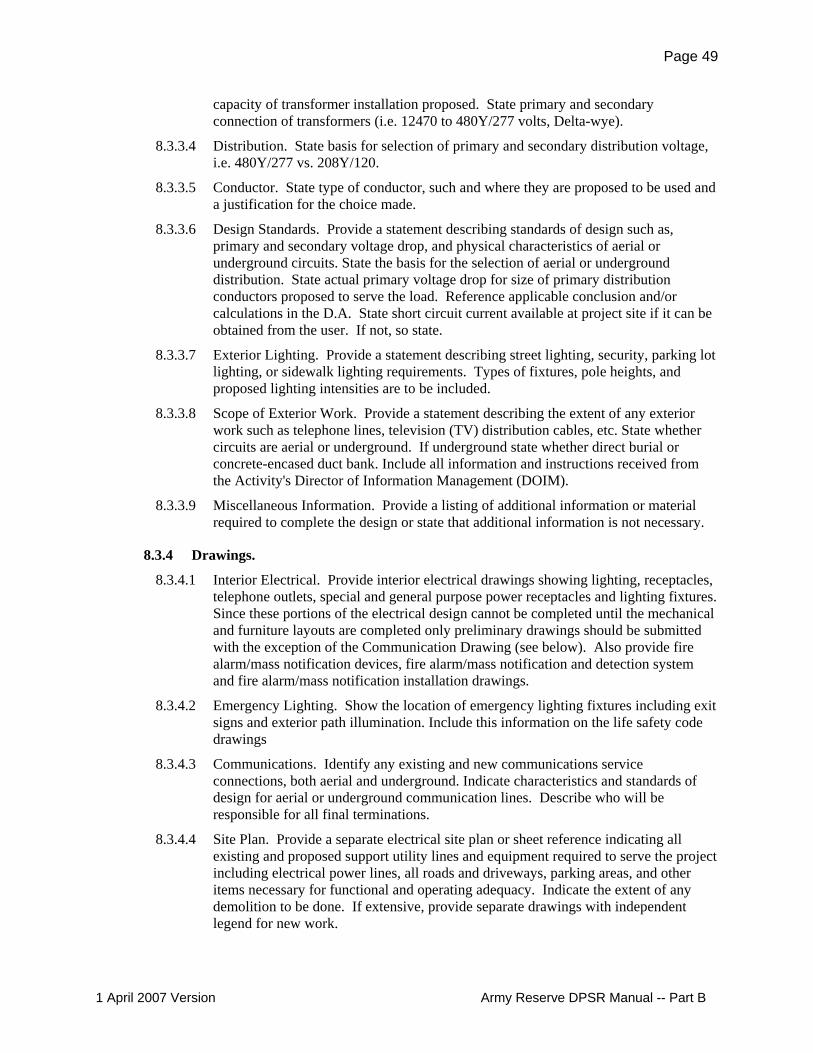
Page 49
capacity of transformer installation proposed. State primary and secondary connection of transformers (i.e. 12470 to 480Y/277 volts, Delta-wye).
8.3.3.4 Distribution. State basis for selection of primary and secondary distribution voltage, i.e. 480Y/277 vs. 208Y/120.
8.3.3.5 Conductor. State type of conductor, such and where they are proposed to be used and a justification for the choice made.
8.3.3.6 Design Standards. Provide a statement describing standards of design such as, primary and secondary voltage drop, and physical characteristics of aerial or underground circuits. State the basis for the selection of aerial or underground distribution. State actual primary voltage drop for size of primary distribution conductors proposed to serve the load. Reference applicable conclusion and/or calculations in the D.A. State short circuit current available at project site if it can be obtained from the user. If not, so state.
8.3.3.7 Exterior Lighting. Provide a statement describing street lighting, security, parking lot lighting, or sidewalk lighting requirements. Types of fixtures, pole heights, and proposed lighting intensities are to be included.
8.3.3.8 Scope of Exterior Work. Provide a statement describing the extent of any exterior work such as telephone lines, television (TV) distribution cables, etc. State whether circuits are aerial or underground. If underground state whether direct burial or concrete-encased duct bank. Include all information and instructions received from the Activity's Director of Information Management (DOIM).
8.3.3.9 Miscellaneous Information. Provide a listing of additional information or material required to complete the design or state that additional information is not necessary.
8.3.4 Drawings.
8.3.4.1 Interior Electrical. Provide interior electrical drawings showing lighting, receptacles, telephone outlets, special and general purpose power receptacles and lighting fixtures. Since these portions of the electrical design cannot be completed until the mechanical and furniture layouts are completed only preliminary drawings should be submitted with the exception of the Communication Drawing (see below). Also provide fire alarm/mass notification devices, fire alarm/mass notification and detection system and fire alarm/mass notification installation drawings.
8.3.4.2 Emergency Lighting. Show the location of emergency lighting fixtures including exit signs and exterior path illumination. Include this information on the life safety code drawings
8.3.4.3 Communications. Identify any existing and new communications service connections, both aerial and underground. Indicate characteristics and standards of design for aerial or underground communication lines. Describe who will be responsible for all final terminations.
8.3.4.4 Site Plan. Provide a separate electrical site plan or sheet reference indicating all existing and proposed support utility lines and equipment required to serve the project including electrical power lines, all roads and driveways, parking areas, and other items necessary for functional and operating adequacy. Indicate the extent of any demolition to be done. If extensive, provide separate drawings with independent legend for new work.
1 April 2007 Version Army Reserve DPSR Manual -- Part B

Page 50
a. Exterior Lighting. Indicate location and type of exterior lighting proposed (street lighting, security lighting, or parking lot lighting).
b. Capacity. Indicate the type, number, location, KVA capacity, primary and secondary voltage of the transformer installation proposed. Identify the capacity of the transformer(s) based on area calculations and site lighting estimates.
8.3.5 Specifications.
Provide a listing of specifications in the design analysis.
8.4 PHASE II–FINAL DESIGN
8.4.1 Design Analysis.
8.4.1.1 Submittal. To support this submittal, provide a complete design analysis, updated to reflect changes from prior submittals. The final DA shall be complete, not just amendments to previously submitted design analyses
8.4.1.2 Calculations. Provide design calculations and supporting documentation to support design considerations. Calculations shall be computed and checked by separate individuals, one of which must be a registered electrical engineer. Indicate the names or initials of these individuals on the page or insert carrying the calculations. Supporting documentation shall be clear, and formulas and references shall be identified. Assumptions and conclusions shall be explained and cross-referencing shall be clear. When a computer program is used, state the name of the program and version used. Include calculations and data for the following in the analysis:
a. Lighting calculations. b. Short-circuit calculations. c. Voltage drop calculations. d. Existing loading data where connections are made to existing transformers or
load centers including method determining the availability of sufficient capacity for the additional loads.
e. Calculations of all connected loads, demand factors, and demand loads by circuit number for each panel and switchboard. Show amp-interrupting circuit ratings for each switchboard and panelboard.
f. Requirements for cathodic protection. g. Trade names are not allowed on the contract plans and specifications. However,
for lighting fixtures and other equipment such as motor control centers, switchgear, bus duct, transformers (where special features are required), special receptacles, etc., Include the current manufacturer and catalog number of the equipment in the D.A.
h. TV System Requirements. i. Lightning Protection Risk Assessment
8.4.2 Drawings.
Complete all of the previous submitted interim drawings, and all additional required drawings for a full design package.
8.4.2.1 Details. Include all details for final package on drawings. For congested areas that might interfere with various electrical systems, cable trays, piping, ducts, etc., thoroughly detail by expanded scale drawings.
1 April 2007 Version Army Reserve DPSR Manual -- Part B

Page 51
8.4.3 Specifications.
Provide a complete set of fully edited specifications from the listing given at the interim design.
8.4.3.1 References. Add publication references, paragraphs, and descriptions for items not adequately covered by specifications.
8.4.3.2 Availability. Ascertain that major or special types of equipment are available commercially.
1 April 2007 Version Army Reserve DPSR Manual -- Part B

Page 52
Chapter 9.0 – COST ENGINEERING
9.1 GENERAL.
9.1.1 Scope.
This chapter provides criteria, requirements and guidance for cost engineering.
Refer to Chapter 1 "All Disciplines" above, paragraph: Reference Documents, and overall gen-eral requirements description.
9.1.2 Cost Estimating Tools.
Either the PArametric Cost Estimating System (PACES) or Micro-Computer Aided Cost Estimat-ing System (MCACES), Second Generation (Mii) shall be used for estimate preparation.
9.1.3 Cost Estimate Organization.
The estimate shall be organized in the Military Work Breakdown Structure (WBS). The Military WBS is the default setting of PACES. The Military WBS is obtained using the Project Template Military of Mii.
9.1.4 Cost Estimate Basis.
The estimate shall be current, complete and accurate; reflecting the information contained in the design documents of the submittal. The level of detail contained in the estimate shall be consis-tent with the level of detail contained in the other elements of the submittal. Square foot (SF) pricing and lump sum (LS) allowances may be used to price elements without sufficient design to warrant more detailed pricing methods.
9.1.5 Escalation and Pricing Adjustments.
9.1.5.1 General – Escalation and Pricing Adjustments shall be determined using sound cost engineering principles. The resulting values and the processes used to develop those values shall be documented in the Cost Estimate Narrative. Cost Escalation Tables and Area Cost Factor Tables will be provided by the Government to assist in determining applicable adjustment factors.
9.1.5.2 PACES – PACES applies escalation to the midpoint of construction as a direct cost adjustment before calculating indirect and owner costs. Review and revise the escalation percentage as needed. Projects having more than one phase may require separate estimates with separate escalation values requiring merging of separate the estimates after PACES processing into one coherent project estimate for presentation purposes. PACES applies locality cost adjustments based on the project location cost factors tab of the Modify Projects Screen. Review and revise location factors as needed.
9.1.5.3 Mii - Project escalation from the date of the estimate to the midpoint of construction shall be expressed as an Owner Cost applied to the project at the highest appropriate title level. Projects having more than one phase may require separate escalation values. The effective date of project source libraries (Cost Book, Labor and Equipment) may not reflect current pricing information for the project area. Pricing adjustments may be used at the markups tab of the Project Library Properties to bring
1 April 2007 Version Army Reserve DPSR Manual -- Part B

Page 53
labor, equipment and material costs to the current date and project area when current project-specific pricing has not been used. It is permissible to use ENR or other reliable sources to more accurately reflect project cost escalation to the midpoint of construction. The Government is the source for the two documents identified. Other documents and sources may be used as well. The Cost Estimate Narrative should include discussion of adjustment factors used and how these factors were determined.
9.1.6 Contingencies.
9.1.6.1 Design Contingencies. Design contingency may be applied at early design stages, depending on the amount of anticipated deviation from ARMY RESERVE standard criteria. See specific design submittal requirements for applicable percentages. When used, assign this contingency as either a Constructor Managed Contingency (CMC) in PACES or as a Prime Contractor Markup after bond at the markups tab of the Project Library Properties in Mii.
9.1.6.2 Construction Contingencies. Construction contingencies shall be applied as Owner Cost at the highest applicable title level. The required contingency percentages are 5% for New Construction and 10% for Renovation/Alteration.
9.1.6.3 Other Contingencies. Contingencies other than those identified above shall not be used in project cost estimates.
9.1.7 Cost Estimate Narrative.
9.1.7.1 General. A narrative shall accompany the estimate identifying the major cost engineering considerations used to prepare the estimate. These considerations may be the assumptions made, or summary restatements of more detailed information contained within the design analysis. The narrative shall reference the design analysis for more information where appropriate. Use of notes fields within the cost estimating tool used is the preferred format for this narrative. Separate narrative is also acceptable. When using notes fields, make notes at the highest levels that include all elements addressed by each note, without including another element.
9.1.7.2 Specific Requirements. Identify the basis for SF pricing or LS allowances used in the estimate. Identify the source of pricing deviation from the standards provided. Deviations from ARMY RESERVE standards are expected as design progresses, reflecting the unique nature of each project. Any deviations made from ARMY RESERVE standards, as they relate to direct costs, indirect costs or owner costs shall be documented, identifying the rationale for such deviations.
9.1.8 Reports
9.1.8.1 General - A Typed Summary Estimate shall be prepared for inclusion with each submittal. See sample spreadsheet in the Appendix.
9.1.8.2 PACES – The reports identified below shall be generated for inclusion with each submittal. Additionally a Building Parameters Report reflecting the data generated during automated estimate creation (PACES Import BLIS/IFC Project) shall be generated for each building in the project and submitted with each project submittal that used automated estimate creation processes.
a. ENG3086 Summary Report b. Subsystem Detail Report c. Building Parameters Report for each building in the estimate
1 April 2007 Version Army Reserve DPSR Manual -- Part B

Page 54
d. Markups Screen Capture e. Escalation Computation (if used) Screen Capture f. Profit Calculation (if used) Screen Capture
9.1.8.3 Mii – The ARMY RESERVE Standard Report Selections shall be generated for inclusion with each submittal. The ARMY RESERVE Standard Report Selections file will be provided by the government.
9.1.9 Quantity Takeoff
Quantity take-offs shall be prepared for all cost items contained within the estimate not generated during automated estimate creation (PACES Import BLIS/IFC Project; and subsequent export to Mii, if used). This includes quantity determinations for SF pricing; quantities associated with LS elements and quantities for PACES Parameters, Assemblies, or Models used in the estimate. A copy of the quantity takeoffs prepared shall be submitted with the estimate. The quantity take-off calculations shall be in a format that permits easy tracking from the drawings to the quantities in-dicated in the estimate.
9.1.10 Cost Estimate Creation Problems and Resolutions.
A separate brief narrative shall be submitted with the estimate, documenting problems encoun-tered during automated estimate creation. If the problems are process related, identify the proc-esses leading to the problems. If the problems are software related, identify the software release and the specific software steps just prior to the problems appearing. Identify the specific steps taken to resolve problems. These narratives may lead to software revisions requiring more formal documentation. If no problems are encountered, the narrative shall consist of a statement to that effect.
9.2 PHASE II–CHARRETTE DESIGN The cost engineering requirements are the same as those identified for the Phase I Project Defini-tion submittal. Provide a PACES estimate reflecting the Charrette product.
9.2.1 Submittal Requirements.
Refer to Chapter 1 "All Disciplines" above, paragraph: Phase II –Charrette Design Meeting And Submittal.
9.3 PHASE II–INTERIM DESIGN A cost estimate may be required if significant changes occurred since the prior submittal. The Project Manager will determine the need for a cost estimate at this submittal. If a cost estimate is required, the cost engineering requirements shall be as indicated below.
9.3.1 Cost Estimate Basis.
The estimate may use the previous Design Phase estimate as its basis. Revise the project estimate as needed to reflect project requirements.
9.3.2 Contingencies.
Design contingencies of 2.5% may be used for projects where more than 50% of the project's de-sign falls outside ARMY RESERVE standard criteria and insufficient design development has occurred to provide a basis for pricing.
1 April 2007 Version Army Reserve DPSR Manual -- Part B

Page 55
9.3.3 Cost Estimate Narrative.
Revisions to the basis estimate shall be documented in the cost estimate narrative.
9.3.4 Mii Estimate Development.
9.3.4.1 Contractor Work Assignment. Project elements shall be assigned to subcontractors consistent with construction contracting practices in the project area.
9.3.4.2 Prime Contractor Indirect Costs. Prime Contractor indirect costs shall be determined reflecting the unique nature of each project. Overhead shall be computed based on an itemized list of the general conditions expense. Profit shall be computed by the weighted factors method, with the factors printed as part of the estimate. Bond shall be computed using Bond Class B.
9.4 PHASE II–FINAL DESIGN
9.4.1 Cost Estimate Basis.
The estimate may use the previous design submittal cost estimate as its basis.
9.4.2 Contingencies.
Only construction contingency applies at this design stage. Discontinue use of design contin-gency, if used during prior submittals.
9.4.3 Cost Estimate Narrative.
Remaining assumptions clearly identified. Efforts to verify assumptions shall be documented. Continue previous requirements.
9.4.4 Current Pricing.
The current, site-specific General Wage Decision shall be used for the labor source library. Cur-rent, site-specific quotes shall be obtained for materials and subcontracted work having signifi-cant impact on project costs.
1 April 2007 Version Army Reserve DPSR Manual -- Part B
Page 56
Chapter 10.0 – ENVIRONMENTAL
10.1 GENERAL.
10.1.1 REQUIREMENTS
Environmental requirements are project and location specific, and could include site asbestos sur-vey and remediation planning, building asbestos survey and demolition, lead paint and environ-mental lead identification and remediation planning, radon assessment, reporting and abatement design, and a variety of other site and building environmental concerns. The A-E will refer to the 1391, data from prior surveys and studies and other information made available from the gov-ernment. Whether these conditions exist, and the extent if any to which they are part of the A-E's project work Scope will be as set forth in the A-E's Appendix A (SOW).
10.1.2 DESIGN CRITERIA
Refer to Chapter 1 "All Disciplines" above, paragraph: Reference Documents, and overall gen-eral requirements description.
10.2 PHASE II–CHARRETTE DESIGN, INTERIM DESIGN, AND FINAL DESIGN
10.2.1 Submittal Requirements.
Refer to Chapter 1 "All Disciplines" above, paragraphs concerning the requirements at each sub-mittal state
10.2.2 BIM Submittal Requirements
Refer To Appendix 1– BIM Instructions, and Appendix 2 – BIM Submittal Requirements
1 April 2007 Version Army Reserve DPSR Manual -- Part B

Page 57
1 April 2007 Version Army Reserve DPSR Manual -- Part B
APPENDIX
APPENDIX 1 – BIM INSTRUCTIONS (Separately bound)
APPENDIX 2 – BIM SUBMITTAL REQUIREMENTS (Separately bound)
APPENDIX – SAMPLE TYPED SUMMARY ESTIMATE (See next page)
An Excel version of the Summary Estimate form is on the Louisville District website, at web-page: http://www.lrl.usace.army.mil/ed2/default.asp?mycategory=212

PROJECT CWE (DD1391 FORMAT) Page 58
1 April 2007 Version rve DPSR Manual -- Part B
Location: Anytown, ST Date Prepared: 19-Mar-07 Design Phase: Description: USARC/OMS/UHS MCAR PA: $14,700,000 Certified Final RFP Mid-Point of Construction: December 2007 Cost Growth: 1.060
Item Quantity Unit Unit Cost Totals **
BASE BID MCAR CONSTRUCTION CONTRACT - CFCI PRIMARY FACILITIES:
Training Facility 60,382.00 SF $118.49 $7,154,600 OMS Building 3,432.00 SF $193.21 $663,100 UHS Building 2,501.00 SF $58.34 $145,900 AT/FP LS $144,000
SUBTOTAL PRIMARY FACILITIES $8,107,600
SUPPORTING FACILITIES:
Electric Service LS $322,600 Water, Sewer & Gas LS $160,400 Paving, Walks, Curbs & Gutters LS $1,040,000 Storm Drainage LS $37,200 Site Improvements & Demolition LS $676,400 Turning Lane LS $100,300 Wash Bay LS $43,500 AT/FP LS $127,300
SUBTOTAL SUPPORTING FACILITIES $2,507,700
SUBTOTAL BASE BID MCAR CONSTR CONTRACT COST - CFCI $10,615,300
Budget Contingency 5.00% $530,800
Subtotal $11,146,100
Supervision and Administration 5.70% $635,300 Design-Build Fee (Incl S&A) 4.03% $449,400
TOTAL BASE BID CONSTR CONTRACT COST- CFCI (MCAR CWE) $12,230,800 $12,230,800
OTHER MCAR PROJECT COSTS
Real Estate by Government $1,300,000 Information Systems by Government $400,000 Utility Payments by Government $725,000
TOTAL OTHER PROJECT COSTS (MCAR CWE) $2,425,000 $2,425,000 TOTAL PROJECT BASE BID COST (MCAR CWE) $14,655,800 $14,655,800
(** All amounts rounded to nearest $100)
Army Rese

PROJECT CWE (DD1391 FORMAT) Page 59
1 April 2007 Version Army Reserve DPSR Manual -- Part B
Location: Anytown, ST Date Prepared: Description: USARC/OMS/U HS MCAR PA: Mid-Point of Construction: December 2007 Cost Growth:
19-Mar-07 $14,700,000 1.060
Design Phase: Certified Final RFP
Item Quantity Unit Unit Cost Totals ** TOTAL PROJECT BASE BID COST (MCAR CWE) $14,655,800 $14,655,800
OPTIONS MCAR CONSTRUCTION CONTRACT - CFCI
Option 1- Loading Ramp LS $55,600 Option 2- Landscaping LS $64,100
Subtotal Options $119,700
Budget Contingency 5.00% $6,000
Options Subtotal $245,400
Supervision and Administration 5.70% $14,000 Design-Build Fee 4.00% $9,800
TOTAL OPTIONS CONSTR CONTRACT COST - CFCI (MCAR CWE) $269,200 $269,200 TOTAL PROJECT COST - Base Bid Plus Options (MCAR CWE) $14,925,000 $14,925,000
(** All amounts rounded to nearest $100)
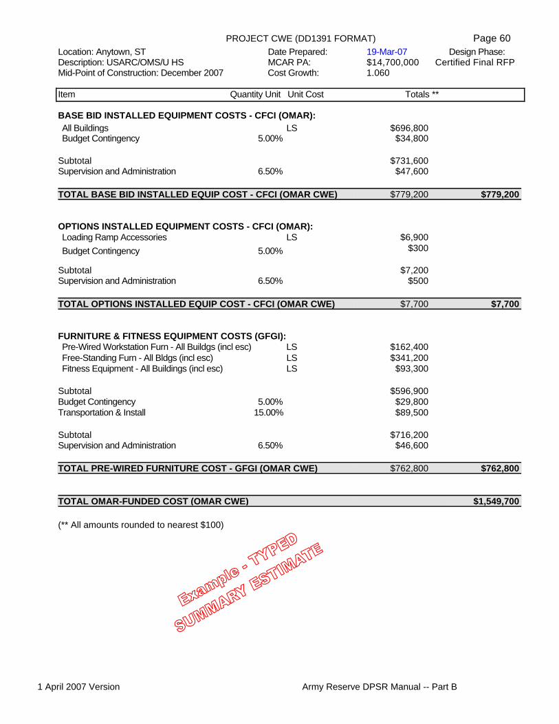
PROJECT CWE (DD1391 FORMAT) Page 60
1 April 2007 Version serve DPSR Manual -- Part B
Location: Anytown, ST Date Prepared: 19-Mar-07 Design Phase: Description: USARC/OMS/U HS MCAR PA: $14,700,000 Certified Final RFP Mid-Point of Construction: December 2007 Cost Growth: 1.060
Item Quantity Unit Unit Cost Totals **
BASE BID INSTALLED EQUIPMENT COSTS - CFCI (OMAR): All Buildings LS $696,800 Budget Contingency 5.00% $34,800
Subtotal $731,600
Supervision and Administration 6.50% $47,600
TOTAL BASE BID INSTALLED EQUIP COST - CFCI (OMAR CWE) $779,200 $779,200
OPTIONS INSTALLED EQUIPMENT COSTS - CFCI (OMAR):
Loading Ramp Accessories LS $6,900 Budget Contingency 5.00% $300
Subtotal $7,200
Supervision and Administration 6.50% $500
TOTAL OPTIONS INSTALLED EQUIP COST - CFCI (OMAR CWE) $7,700 $7,700
FURNITURE & FITNESS EQUIPMENT COSTS (GFGI):
Pre-Wired Workstation Furn - All Buildgs (incl esc) LS $162,400 Free-Standing Furn - All Bldgs (incl esc) LS $341,200 Fitness Equipment - All Buildings (incl esc) LS $93,300
Subtotal $596,900
Budget Contingency 5.00% $29,800 Transportation & Install 15.00% $89,500
Subtotal $716,200
Supervision and Administration 6.50% $46,600
TOTAL PRE-WIRED FURNITURE COST - GFGI (OMAR CWE) $762,800 $762,800
TOTAL OMAR-FUNDED COST (OMAR CWE) $1,549,700
(** All amounts rounded to nearest $100)
Army Re
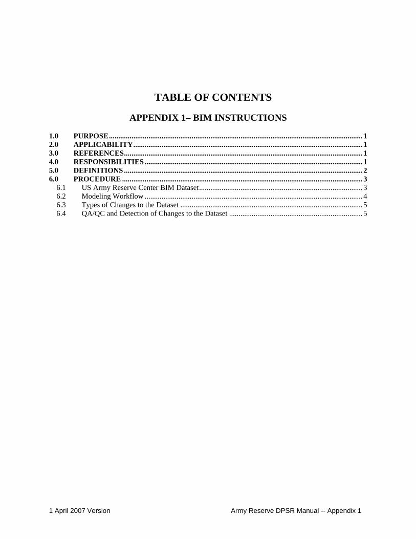
TABLE OF CONTENTS
APPENDIX 1– BIM INSTRUCTIONS 1.0 PURPOSE....................................................................................................................................... 1 2.0 APPLICABILITY.......................................................................................................................... 1 3.0 REFERENCES............................................................................................................................... 1 4.0 RESPONSIBILITIES.................................................................................................................... 1 5.0 DEFINITIONS ............................................................................................................................... 2 6.0 PROCEDURE ................................................................................................................................ 3
6.1 US Army Reserve Center BIM Dataset....................................................................................... 3 6.2 Modeling Workflow .................................................................................................................... 4 6.3 Types of Changes to the Dataset ................................................................................................. 5 6.4 QA/QC and Detection of Changes to the Dataset ....................................................................... 5
1 April 2007 Version Army Reserve DPSR Manual -- Appendix 1

Page 1
APPENDIX 1– BIM INSTRUCTIONS
1.0 PURPOSE
This work instruction will serve as a guide to the AE Building Information Model (BIM) design teams in the use of the US Army Reserve Center BIM Dataset. The work instruction will guide the enhancement of the US Army Reserve Center BIM Dataset and corresponding module catalogue. It will be used during Army Reserve Building Information Model (BIM) design projects. It describes how the Louisville District will identify, check and implement change to the Army US Army Reserve Center BIM Dataset and module catalogue based on input from In-house and AE design submittals, enhancements to the Army Reserve criteria, and BIM software improvements. It will also provide BIM design teams with direction of the BIM workflow and how to handle changes to this dataset during the design phase and at each submittal.
2.0 APPLICABILITY
This work instruction applies to all drawing plans, cost estimates, specifications and design analysis generated utilizing Building Information Modeling (BIM) techniques for all design phases, including design review submittals, documents issued to bidders, as-award documents, and as-built documents for Army Reserve projects designed in-house and by others.
Contract requirements: BIM may be a contract requirement, or may be at designer's option. Refer to the project's contract documents. For example Section 01 03 00.00 48 DESIGN SUBMISSION REQUIREMENTS AFTER AWARD has alternate text such as below governing whether BIM is a part of the work:
"[Prepare documents using Building Information Management (BIM) technology as described in the Appendices of the "Reserve Design Process and Submittal Requirements Manual.] "[Preparation of the documents using Building Information Management (BIM) technology as described in the Appendices of the "Reserve Design Process and Submittal Requirements Manual is at the Designer's option, and is not a Contract requirement.]"
For D-B-B projects refer to the A-E's contract Appendix A (Statement of Work) for the project's specific BIM requirements.
3.0 REFERENCES
A/E/C CADD Standard Release 3.0, September 2006.
4.0 RESPONSIBILITIES
Louisville District BIM manager is responsible for the maintenance, distribution and use of the US Army Reserve Center BIM Dataset CD, which includes the USACE/USAR Workspace.
The AE design team is required to deploy the US Army Reserve Center BIM Dataset and the USACE/USAR Workspace on their server system as to allow their design team the proper tools to create the BIM as it is defined for their specific project. Instructions for server deployment are provided with each release of the US Army Reserve Center BIM Dataset.
1 April 2007 Version Army Reserve DPSR Manual -- Appendix 1

Page 2
Design team leaders are responsible for creating project designs within the provided framework and establishing a BIM that contains useful and valuable data for the Corps of Engineers and the Army Reserves.
5.0 DEFINITIONS
Building Information Model (BIM) – A collection of electronic drawing and data files in the project folder structure. The collection is coordinated and has relationships built so that the information can be easily extracted in the form of drawings, details, schedules, quantity takeoffs, renderings, animations, and any other format needed during the design and/or construction process. The Army Reserves utilizes Bentley’s TriForma for BIM file creation and data extraction. This set of files contains many different types of files including .dgn and .xml.
Dataset- The information that describes the non-graphical and graphical data tied to the objects within the TriForma BIM.
Data Group – Specific spatial and text data connected to BIM objects contained in specific dataset folders. These same files contain the information that describes how this information is requested for each object and displayed in schedules.
Workspace – The framework in which a set of folders together with MicroStation, TriForma, and discipline application configuration files which are created to manipulate where and how TriForma records data and operates. This is utilized by the Corps of Engineers in order to gain consistent data when receiving BIM submittals and deliverables.
Object – This term is used to describe an electronic element within a BIM that represents a design element. It may be a 2d or 3d object and it must either have data connected to it (intelligent object) even if it is simply named for counting purposes or it can be a programmed to respond to input automatically (Smart object) such as a parametric cell.
Parts – A part is the name of the center of information within the TriForma dataset Explorer for repetitive or single objects within a BIM. A part holds graphic and non-graphic information about those objects. It contains component and extraction information. All Army Reserve Parts comply with the A/E/C CADD Standard.
Family – A family is a logical organization of parts within the TriForma Dataset Explorer. The Army Reserve dataset organizes the parts into constructions systems such as “Exterior Walls” or “Spaces”.
Component – A component is specific data which is tied to a part and is defined within the TriForma Dataset explorer. A single component may be tied to many different parts because a component can describe measurements for quantity takeoffs, specification sections based on CSI format and even cost data.
Cell – A cell is a type of object as described above. It is saved in a specific format in order to allow ease of replication and reuse. There are three types of TriForma cells; parametric, compound and regular cells. They can be either 2d or 3d.
Module – A module is a collection of objects required for a specific Army Reserve space as described in the Army Reserve Center Design Guide. The size of the module is base on the design guide programmed area, but it may be edited and manipulated for use within specific designs. All objects and elements in a module are modeled to the A/E/C CADD Standard.
Model File - See the A/E/C CADD Standard release 3.0. In the BIM process this is also the extraction file.
Sheet File – See the A/E/C CADD Standard release 3.0
1 April 2007 Version Army Reserve DPSR Manual -- Appendix 1

Page 3
Seed File - A seed file is simply a file with as many default configuration setting completed for a project. The seed files provided in the Default Dataset have been created with the proper working units, color table, and many other settings complete. This does not mean that the seed file will have everything needed for all projects, but it is provided in order to clarify and simplify specific settings.
Level Library – A level library file is utilized during the boot up of TriForma by configuration files to attach levels required for all parts within a dataset. It does not replicate the seed file levels needed to comply with the A/E/C CADD Standard. It is provided to make sure that no parts are placed without the proper level.
Design - A general term for the efforts of Engineering Division. For the purpose of this work instruction, it is limited to the preparation of plans, specifications, and design analysis. The design phase requirements will vary by project, as determined by the Acquisition Strategy Meeting. All plans and specifications developed shall be clearly identified as to the phase of design it represents.
Deliverable - The product of engineering and design efforts. Typically, this would be the concept submittal and the corrected final design. A deliverable may have multiple phases.
Project Engineer/Architect (PE/A) - Individual assigned as the technical manager responsible for day-to-day coordination of the design. The PE/A represents the design team on the project team.
Project Lead Technician (PLT) - Technician responsible for coordinating the efforts of all modelers and technicians within the model. The PLT is selected for each project from the technicians assigned to a project and is generally from the same section as the PE/A. This person may also be called a lead modeler.
6.0 PROCEDURE
6.1 US Army Reserve Center BIM Dataset
At the beginning of each project the designer will download and/or receive, via compact disk, the most recent release of the US Army Reserve BIM Dataset. The Corps of Engineers, Louisville District will provide this dataset at request to Corps of Engineers or A/E designers. It will include the following:
a. Module Catalogue b. Cell Libraries (2d, 3d, compound, and parametric) c. Data Group System d. Family, Part, and Component Definitions e. Seed Files f. Level Libraries g. BIM Workspace h. Sheet Border i. Text Styles j. Dimension Styles k. DGN Libraries l. Color Table m. Font Library
The US Army Reserve Center BIM Dataset can be used with confidence that it is in compliance with the A/E/C CADD Standard and the Army Reserve Design Guide for Army Reserve Centers. Anything found in the delivered dataset that does not comply with the A/E/C CADD Standard should be reported to the LRL BIM Manager. The US Army Reserve Center BIM Dataset has been created by LRL and all data provided has been reviewed by the Army Reserve Criteria Control Board and the LRL BIM Manager for compliance with the CADD Standard.
1 April 2007 Version Army Reserve DPSR Manual -- Appendix 1

Page 4
6.2 Modeling Workflow
Shown below is the suggested workflow for the AR BIM design team. Using this modeling workflow is not required nor checked, but the US Army Reserve Center BIM Dataset was created with this workflow in mind.
2d Detailing
ModulesModules
Cells(2d and/or 3d)
Cells(2d and/or 3d)
Weapons Sim.
Offices
Arms Vault
System ModelsSystem Models
Master ModelNo modeling should be done here. Referencing and renderings is enough
Extractions (Tri-Service Model files)
Extractions (Tri-Service Model files)
Sheet FilesSheet Files
Locker Rm
Plumbing fixtures
Mechanical fixtures
Floor Plan
Framing Plan
Renderings
Animations
Floor Plan
Elevations
Ceiling Plan
Sections
Details
CeilingPlan
Furniture
Architectural Details
Structural Details
Foundation Plan
Mechanical
FurnitureFloorPlan
Schedules
RoofPlanFramingPlan
Cop
y
Cop
yC
opy
Ref
eren
ce
Ext
ract
ion
ReferenceDefault
Data
Designer Input
PLT
Modeling WorkflowModeling Workflow
NOTE: Any design changes to the extraction or sheet file makes the BIM obsolete. Best practice is to make changes to the system models, and then re-run the extractions.
Modules and Cells
The model workflow that we use begins with pre-defined data known as cells and modules. This data provided at the start of a project and contains only data that has been through the quality control process. These are used to give the designer a starting point in the creation of a BIM. Each module is a space (room) in the Army Reserve design guide. It does not contain all of the data needed to create a BIM, but it is a good start and everything provided is compliant with the CADD standard as well as the Design guide.
System Models
The default data is a tool for the designer during the creation of the system models. System models are the heart and sole of the BIM. This is where the design is worked out and all model output comes from this location. This is where the workshop focus is. Digital construction must be embraced here in order to realize the benefit of significantly reduced change orders during construction.
Master Model
1 April 2007 Version Army Reserve DPSR Manual -- Appendix 1

Page 5
The Project Lead Technician references all system models in order to create a Master Model. Other less encompassing Master Models can be created for specific reasons such as specific discipline extractions. Extractions are cut here.
Extractions
Each discipline creates their extractions independently due to the complexity of the output data. These extractions must be created within the discipline tools in order to make use of rules created for them. Extractions as well as other types of output should not be put off until modeling is complete. They are easily updated and can be created at the earliest phases. We have created default extractions and schedules within the USAR/USACE BIM Workspace.
Sheet Files
The extractions are referenced to the standard sheet file complying with CADD standards. The USAR/USACE BIM Workspace developed between Louisville District and Bentley moves the tedious task of selecting levels, line weights, sheet borders, text styles, dimensioning styles, line styles and more into the background the way DOS is running behind Windows.
Quality Check (not shown above)
The BIM Manager must check all of the files against drawing library files using the standards checker utility within Bentley tools. This ensures that the proper family, parts, dimension style, line styles, text styles, among others were used and that the output complies with CADD standards. In order to take advantage of this tool, a strong dataset and workspace must be established. Model interferences must also be checked. Each discipline and the Project Lead Technician should run the Interference Manager in order to identify design or model conflicts. We did this utilizing Bentley Navigator together with Interference Manager.
6.3 Types of Changes to the Dataset
The following are avenues of change to the default dataset considered in this work instruction:
a. Design Changes – The Default Dataset is not intended to be the all inclusive design tool for Army Reserve Centers. Therefore, additions and changes to the delivered dataset are expected.
b. Criteria Changes – Due to the changing needs of the client, minor changes to the design guide must take place from time to time. These changes must be accounted for in the dataset module catalogue and the dataset.
c. Update to the Software - BIM is a relatively new and evolving process. The Bentley Building tools are continually updated to account for additional data and disciplines being included in the model.
d. BIM Manager Input – The Default Dataset is not considered complete. It is a work in progress and will remain so. As the Louisville District BIM manager detects needs for changes, they will be made.
e. BIM Standards – The A/E/C CADD Standard was developed from a 2d perspective. It utilizes levels in order to differentiate vector elements. They are sometimes used to represent a 3rd dimension that is not modeled (e.g., topographic elevation or ceiling grid). There are obvious differences in the use of for levels when creating a BIM, therefore the need of additional levels is inevitable. Levels are the biggest area of change to the A/E/C CADD standard, but not all and it is impossible to estimate all needs, and so for now, a BIM Standard must rely on the established CADD Standard and make changes as it progress.
6.4 QA/QC and Detection of Changes to the Dataset
1 April 2007 Version Army Reserve DPSR Manual -- Appendix 1

Page 6
Proposed changes to the BIM dataset must be received, evaluated, and judged without slowing the design process. Therefore we have developed a submittal process for changes to the CADD and BIM standards during the design phase. For change submittal, visit the https://tsc.wes.army.mil/comments/AECSDS_comments/AECSDS-CommentForm.asp website. Once there, follow all instructions and submittal requirements. The design team should make the needed change, submit the change, and go on with the design as if it had been accepted. However, the design team must be willing to reverse or alter their model if their submitted change is not accepted to standard.
Designers, both AE and In-House, will perform Quality Control (QC) checks of the dataset just prior to each submittal. Documentation created during those checks shall be submitted at the time of the project submittal BIM Data Report. Any elements within the model not meeting the requirements shall have an explanation of the reason that they were left as they were. These issues should be brought to the attention of the LRL BIM Manager for consideration of standards updating at the dataset review meeting. There are four types of checks that must be made on the model:
1. Visual Check – This can be accomplished by checking the model small segments at a time using cameras within MicroStation or the entire model using Bentley Navigator. The main reason for this check is to insure the design intent has been followed and that there are no unintended elements in the model.
2. Interference Check – This check is performed using Bentley Navigator together with Bentley’s Interference Manager. It is used to locate problems in the model where two objects are occupying the same physical space.
3. Standards Check – This is performed using the “standards checker” tool within the Bentley software. This is used to insure that the fonts, dimensions, line styles, levels and other issues are followed per the BIM and CADD standards.
4. TriForma Element Validation – Using the validation tool on the datagroup dialogue will run this tool and it is used to insure that the dataset has no undefined or incorrectly defined elements.
At the time of delivery of each design submittal, the design team will make arrangements for a dataset review meeting with the LRL BIM Manager. This meeting is intended to communicate changes and additions to the US Army Reserve Center BIM Dataset. This will enable the BIM manager to determine what elements should be considered for inclusion to the US Army Reserve Center BIM Dataset future releases. This meeting will also give the AE an opportunity to suggest changes to the process, workspace, standards, or dataset. This meeting will be coordinated through the Project Manager.
Each delivered design submittal will be reviewed for quality assurance (QA) as explained in the QC/QA Processes for Study/Design Phase. In addition, BIM files delivered with each submittal will be evaluated for differences from the default dataset folders and files to determine if the proper files within the dataset have been edited. The LRL BIM manager will also do QA of the submitted BIM files to insure that the QC was properly performed.
The results of these sources of change will be evaluated by the Louisville District BIM manager who will select only relevant and quality data to be used for enhancement of the US Army Reserve Center BIM Dataset.
1 April 2007 Version Army Reserve DPSR Manual -- Appendix 1

TABLE OF CONTENTS
APPENDIX 2-- BIM SUBMITTAL REQUIREMENTS
CHAPTER 1.0 – ALL DISCIPLINES .......................................................................................................... 1
1.1 GENERAL.................................................................................................................................... 1 1.2 CHARRETTE SUBMITTAL ....................................................................................................... 1 1.3 INTERIM SUBMITTAL .............................................................................................................. 2 1.4 FINAL SUBMITTAL ................................................................................................................... 3 1.5 RTA / BCOE SUBMITTAL REQUIREMENTS.......................................................................... 4 1.6 AS-AWARDED SUBMITTAL REQUIREMENTS .................................................................... 4 1.7 AS-BUILT SUBMITTAL REQUIREMENTS ............................................................................. 4
CHAPTER 2.0 – CIVIL ................................................................................................................................. 6 2.1 GENERAL.................................................................................................................................... 6 2.2 CHARRETTE SUBMITTAL ....................................................................................................... 6 2.3 INTERIM SUBMITTAL .............................................................................................................. 6 2.4 FINAL SUBMITTAL ................................................................................................................... 6
CHAPTER 3.0 – SITE MECHANICAL UTILITIES ................................................................................. 8 3.1 GENERAL.................................................................................................................................... 8 3.2 CHARRETTE SUBMITTAL ....................................................................................................... 8 3.3 INTERIM SUBMITTAL .............................................................................................................. 8 3.4 FINAL SUBMITTAL ................................................................................................................... 8
CHAPTER 4.0 – ARCHITECTURAL ......................................................................................................... 9 4.1 GENERAL.................................................................................................................................... 9 4.2 CHARRETTE SUBMITTAL ....................................................................................................... 9 4.3 INTERIM SUBMITTAL .............................................................................................................. 9 4.4 FINAL SUBMITTAL ................................................................................................................. 11
CHAPTER 5.0 – INTERIOR DESIGN ...................................................................................................... 13 5.1 GENERAL.................................................................................................................................. 13 5.2 CHARRETTE SUBMITTAL ..................................................................................................... 13 5.3 INTERIM SUBMITTAL ............................................................................................................ 13 5.4 FINAL SUBMITTAL ................................................................................................................. 13
CHAPTER 6.0 – STRUCTURAL ............................................................................................................... 14 6.1 GENERAL.................................................................................................................................. 14 6.2 CHARRETTE SUBMITTAL ..................................................................................................... 14 6.3 INTERIM SUBMITTAL ............................................................................................................ 14 6.4 FINAL SUBMITTAL ................................................................................................................. 14
CHAPTER 7.0 – MECHANICAL - HVAC, PLUMBING AND FIRE PROTECTION......................... 16 7.1 GENERAL.................................................................................................................................. 16 7.2 CHARRETTE SUBMITTAL ..................................................................................................... 16 7.3 INTERIM SUBMITTAL ............................................................................................................ 16 7.4 FINAL SUBMITTAL ................................................................................................................. 17
CHAPTER 8.0 – ELECTRICAL ................................................................................................................ 18 8.1 GENERAL.................................................................................................................................. 18 8.2 CHARRETTE SUBMITTAL ..................................................................................................... 18 8.3 INTERIM SUBMITTAL ............................................................................................................ 18 8.4 FINAL SUBMITTAL ................................................................................................................. 18
1 April 2007 Version Army Reserve DPSR Manual -- Appendix 2

Page 1
APPENDIX 2 – BIM SUBMITTAL REQUIREMENTS
Chapter 1.0 – ALL DISCIPLINES
1.1 GENERAL Applicability: BIM may be a contract requirement, or may be at designer's option. Refer to the project's contract documents. For D-B-B projects refer to the A-E's contract Appendix A (State-ment of Work) for the project's specific BIM requirements.
This chapter states the minimum Building Information Model (BIM) requirements for each sub-mittal phase. All submitted BIM models, extraction files, extraction definitions, sheet files, ren-derings, Navigator files, and output files shall be created using Bentley Systems Inc, Building Suite of tools and in the version of those tools in which the Army Reserve Dataset CD was pro-vided. This dataset is dependent on the specific versions of the Bentley suite of building tools. Only the versions of software that are listed in the BIM dataset read me file, included on each USARC Default dataset CD, are permitted to be used. See USARC BIM dataset read me file for specific instructions for deployment of dataset.
Since the concept of the AR BIM is to digitally build the structure, it is inherent that all design work be preformed from the perspective that all elements and relationships between them are modeled, as they would be built. The designer shall use sound engineering, architectural, and construction judgment when placing elements on specific parts within families within BIM. The family and part configuration provided within this dataset does not intend to account for all types of construction elements; rather the intent is to establish a solid starting base to be built upon. The designer of record must understand the use of parts within the BIM in order for them to expand this list for their specific project needs. Family and parts must be used to differentiate groups of elements with the BIM in order to create the following:
• Quantity takeoffs for calculation of cost of all construction materials and activities related to the installation of those materials.
• Extraction and re-symbolization of model data to files for the creation of contract draw-ings on sheet borders.
• Renderings of the BIM for communication of design and as a deliverable to the client.
• Support of the construction model data extraction
• Querying of elements so to make simultaneous changes to multiple design elements as needed.
• Level management – to comply with A/E/C CADD Standards and National BIM Stan-dards
• Design schedules and construction sequencing.
1.2 CHARRETTE SUBMITTAL Include in this BIM submittal all of the major components of civil and architectural. All Drawings supporting this submittal shall come directly from the model using the extraction processes. Civil
1 April 2007 Version Army Reserve DPSR Manual -- Appendix 2

Page 2
drawings for this submittal can be drawn using traditional CADD.
Submit a completed space layout drawing using Bentley Architecture and the USARC Default Dataset . Spaces shall indicate room names and numbers along with the placed and programmed square footages. Spaces shall also have datagroup information associated with from the USARC Default Dataset.
Provide an exported Excel spreadsheet space schedule form the space layout drawing to validate the 1391/1390 and 5034R. Spreadsheet shall indicate the differences in areas between approved square footages and placed square footages.
Refer to Part B Detailed Design (Phase II) Chapter 1 "All Disciplines" paragraph: Phase II –Charrette Design Meeting And Submittal for drawing deliverables.
Also refer to disciplines specific BIM requirements that are out-line below.
1.3 INTERIM SUBMITTAL Include in this BIM submittal all of the major components of civil, architecture, interior design, structural, mechanical, electrical, fire protection, and information systems as well as complete building elevations. The following paragraphs describe most conditions for when an element shall and shall not be in the model. In general, all elements normally shown in ¼" – 1'-0" scale drawing or detail shall be included in the model as a minimum requirement. It is left to designer's judgment for additional detailing in the model.
All files must be in the proper location within the USACE/USAR Workspace delivered on the Army Reserve Center BIM Dataset CD (Refer to Appendix 1 – BIM Work Instructions). The Louisville District must be able to recreate the BIM process in order to review the drawings and model. Simple images are not acceptable and are not direct output of the BIM.
Schedules – Provide a door and room finish schedules from the BIM indicating the materials and finishes used in the design. The room finish schedule template is provided within the dataset. Also a special item schedule and/or notes shall be provided indicating any special items that will be required for the design. Due to the specific nature of the special items schedule, it shall not be required as output of the BIM, but there are additional templates in development, and these will be required on future projects to support specific output tasks of the design team.
Extractions – The extraction process shall be well established at the interim submittal. Most ex-traction definitions shall be completed within the master models. It is suggested that the design team begin with the extraction definitions provided with the dataset and build from there.
Datagroup – The Datagroup information shall be complete at the interim submittal and shall not be edited beyond this stage unless large building usage changes have been made. All Excel spreadsheet output shall be linked to a sheet design file and submitted.
Dataset – Resolve all dataset issues. Submit any additional families, parts, line styles, special di-mension styles, or level not provided in the US Army Reserve Center BIM Dataset CD to the Louisville District BIM Manager at this and every submittal. (See Appendix 1 - "QA/QC and De-tection of Changes to the Dataset" for guidance on standard and dataset change requests)
Quality verification – Complete all quality checks listed in Appendix 1 - "QA/QC and Detection of Changes to the Dataset" for all files and disciplines created with BIM. Submit output of those checks with the normal submitted materials. In addition, submit documentation of all unresolved interferences, standards, TriForma elements along with an explanation. Complete a quality check for compliance with the A\E\C CADD Standards on the final file condition prior to submittal and include the results of that standard check in the submittal.
1 April 2007 Version Army Reserve DPSR Manual -- Appendix 2
Page 3
Drawings – Use the BIM to extract the construction documents. Standard details, index sheet, and other typical drawings need not be extracted from the BIM.
Part and Family Report – The model must support the Part and Families that are contained on the US Army Reserve Center BIM Dataset CD (Refer to Appendix 1 – BIM Work Instructions). Submit an Excel report that validates the parts and families of the BIM model.
Interference Manager Report- Check the BIM models with Bentley's Interference Manager. Check the interferences between structural, mechanical, and architectural models. Generate a re-port showing sign off's for soft and hard interferences from the design team. Submit this report as part of the interim and final submittals. Also submit a Bentley Navigator file to highlight struc-tural and mechanical interferences.
Configuration verification report- Generate and submit a configuration report showing that all system valuables are using the correct workspace and datasets.
1.4 FINAL SUBMITTAL Include in the final submittal all of the major components of civil, architecture, interior design, structural, mechanical, electrical, fire protection, and information systems created with BIM. In-corporate all changes and comments from previous submittals into all BIM models. The follow-ing paragraphs describe most conditions for when an element shall or shall not be in the model. In general, all elements normally shown in ¼" = 1'-0' scale drawing or detail shall be included in the model as a minimum requirement. It is left to designer's judgment for addition detailing in the model.
All files must be in the proper location within the USACE/USAR Workspace delivered on the US Army Reserve Center BIM Dataset CD (Refer to Appendix 1 – BIM Work Instructions). The Louisville District must be able to recreate the BIM output files from the BIM in order to review the drawings and model. Simple images are not acceptable and are not direct output of the BIM.
Schedules – All instance data shall be reported into the appropriate schedules. Also any special schedules and/or notes shall be provided indicating any special items that will be required for the design.
Extractions – The extraction process shall be completed at this time.
Datagroup – The Datagroup information shall be complete.
Dataset – All dataset issues shall be resolved at the interim submittal. Any additional families, parts, line styles, special dimension styles, or level not provided in the US Army Reserve Center BIM Dataset CD shall be submitted to the Louisville District BIM Manager at this and every submittal. (See Appendix 1 - "QA/QC and Detection of Changes to the Dataset" for guidance on standard and dataset change requests)
Quality verification – Complete all quality checks listed in Appendix 1 - "QA/QC and Detection of Changes to the Dataset" for all files and disciplines. Submit output of those checks with the normal submitted materials. In addition, submit documentation of all unresolved interferences, standards, TriForma elements along with an explanation. Complete a quality check for compli-ance with the A\E\C CADD standards on the final file condition prior to submittal and include the results of that standard check in the submittal.
Design Analysis - The model must support the design analysis whenever possible and prudent. That decision must be made by comparing the value of the output from the model versus the work added to computer processing which is affected by the level of detail. If the project has a kitchen, then the information within the kitchen must be equivalent to data provided in cut sheet details.
1 April 2007 Version Army Reserve DPSR Manual -- Appendix 2

Page 4
Drawings – Use the BIM to extract the construction documents. Standard details, index sheet, and other typical drawings need not be extracted from the BIM.
Part and Family Report – The model must support the Part and Families that are contain on the US Army Reserve Center BIM Dataset CD (Refer to Appendix 1 – BIM Work Instructions). Submit a report that validates the parts and families of the BIM model.
Interference Manager- Run Interference Manager on the BIM models. Check the interferences be-tween structural, mechanical, and architectural models. Generate a report showing sign-offs for soft and hard interferences from the design team. Submit this report as part of the interim and fi-nal submittals. Also submit a Bentley Navigator file to highlight structural and mechanical inter-ferences.
1.5 RTA / BCOE SUBMITTAL REQUIREMENTS
1.5.1 SYSTEM MODELS
The Systems models shall be complete and include all approved comments from the previous submittals that affect the models. Submittals must include the extraction files, sheet files, special patterning, line styles, cells, referenced files or other specific files used to create the drawings as output of the model, and any modifications to the USARC BIM dataset.
1.5.2 DRAWING EXTRACTION REQUIREMENTS
All extractions shall be updated to include all approved comments from the previous submittal.
Also see discipline specific requirements in Part B – Detailed Design (Phase II)
1.6 AS-AWARDED SUBMITTAL REQUIREMENTS
1.6.1 SYSTEM MODELS
The As-Awarded models shall be complete and incorporate all amendments from the previous (RTA/BCOE) submittal that affect the models. Submittals must include the extraction files, sheet files, special patterning, line styles, cells, reference files or other specific files used to create the drawings as output of the model, and any modifications to the USARC BIM dataset.
1.6.2 DRAWING EXTRACTION REQUIREMENTS
Update all extractions to include all approved comments from the previous submittal.
Also see discipline specific requirements in Part B – Detailed Design (Phase II)
1.7 AS-BUILT SUBMITTAL REQUIREMENTS
1.7.1 SYSTEM MODELS
Responsibility for production of the As-Built BIM submittal -- A-E or Contractor -- will be as de-fined in the SOW, and/or in the Construction Contract documents.
The As-Built models shall be complete and incorporate all modifications from the previous (As-Awarded) submittal that affect the models. Submittals must include the extraction files, sheet files, special patterning, line styles, cells, reference files or other specific files used to create the drawings as output of the model, and any modifications to the USARC BIM dataset.
1 April 2007 Version Army Reserve DPSR Manual -- Appendix 2

Page 5
1.7.2 DRAWING EXTRACTION REQUIREMENTS
Update all extractions to include all approved comments from the previous submittal.
Also see discipline specific requirements in Part B – Detailed Design (Phase II)
1 April 2007 Version Army Reserve DPSR Manual -- Appendix 2
Page 6
Chapter 2.0 – CIVIL
2.1 GENERAL This chapter states the minimum BIM requirements for each submittal phase.
2.2 CHARRETTE SUBMITTAL Using the site survey provide (see Part B- Detailed Design (Phase II) Chapter 2, paragraph "Site Survey"), create and submit the following model(s):
Digital Terrain Model (DTM) - the DTM will show the new and existing contours together to make-up the overall site model.
The DTM will show roads, parking and building footprint(s) of the approved site and building layouts from the charrette meeting.
All existing utilities need to be indicated in the DTM. The utilities can be placed as simple 2D geometry for this submittal.
Extract all drawings from this model. Also refer to Part B Detailed Design (Phase II) Chapter 1 "All Disciplines" paragraph: Phase II –Charrette Design Meeting And Submittal for drawing de-liverables.
2.3 INTERIM SUBMITTAL
2.3.1 Civil Models
The Civil models may vary in level of detail for individual elements within a model, but at a minimum must include all features that would be included on an appropriately scaled drawing. Additional minimum requirements are listed below.
Digital Terrain Model (DTM) – This model will show existing and new grading contours. This model will also show all existing structures that are remaining. Indicate the new building(s), pavement, drainage inlets, structures, swales and/or detention areas.
Drainage Model – This model will show existing and proposed new piping.
Storm and Sanitary Model – This model will show sewer structures and pipes.
Utility Model – This model will show connection of new utilities from the building to the existing utilities. This model will also show all existing underground utilities along with all new and exist-ing above ground utilities.
Road and Parking Model – This model will show roadway and parking lot facilities. Also existing ground and utilities crossing will be indicated in this model.
Master Site Model – this model will have all civil design models referenced in to create drawing extractions. All drawings shall be extracted form the BIM master model.
2.3.2 DRAWING EXTRACTION REQUIREMENTS
See discipline specific requirements in Part B – Detailed Design (Phase II)
2.4 FINAL SUBMITTAL The Civil models may vary in level of detail for individual elements within a model, but at a
1 April 2007 Version Army Reserve DPSR Manual -- Appendix 2

Page 7
minimum must include all features that would be included on an appropriately scaled drawing. Additional minimum requirements are listed below.
Digital Terrain Model (DTM) – This model will show existing and new grading contours. This model will also show all existing structures that are remaining. Indicate the new building(s), pavement, drainage inlets, structures, swales and/or detention areas.
Drainage Model – This model will show existing and proposed new piping.
Storm and Sanitary Model – This model will show sewer structures and pipes.
Utility Model – This model will show connection of new utilities from the building to the existing utilities. This model will also show all existing underground utilities along all new and existing above ground utilities.
Road and Parking Model – This model will show roadway and parking lot facilities. Also existing ground and utilities crossing will be indicated in this model.
Master Site Model – this model will have all civil design models referenced in to create drawing extractions. All drawings shall be extracted form the BIM models.
2.4.1 DRAWING EXTRACTION REQUIREMENTS
See discipline specific requirements in Part B – Detailed Design (Phase II)
1 April 2007 Version Army Reserve DPSR Manual -- Appendix 2

Page 8
Chapter 3.0 – SITE MECHANICAL UTILITIES
3.1 GENERAL This chapter states the minimum BIM requirements for each submittal phase.
3.2 CHARRETTE SUBMITTAL There are no BIM requirements for this phase.
3.3 INTERIM SUBMITTAL BIM guidelines have not been determined at this time.
3.4 FINAL SUBMITTAL BIM guidelines have not been determined at this time.
1 April 2007 Version Army Reserve DPSR Manual -- Appendix 2

Page 9
Chapter 4.0 – ARCHITECTURAL
4.1 GENERAL This chapter states the minimum BIM requirements for each submittal phase.
4.2 CHARRETTE SUBMITTAL The design team will in a maximum of thirty (30) days to prepare the following documents:
• Completed single line space layout drawing using the Create Space tool in Bentley Build-ing Suite of tools.
• Exported Excel spread sheet from the space layout using Instance Data tool. The spread sheet will contain the following information: Room name, room number, building type, floor location, authorized square footages and placed square footages.
• Validation of 1391 and 5034R in a spreadsheet format that will show approved square footages and area differences in program square footages.
• Army Reserve standard modules that come with the Army Reserve Data set (Refer to Appendix 1 – BIM Work Instructions) will be added. Examples: kitchen, weapons simu-lator, standard offices, and vault.
• Extracted floor plan from the 3D model. Floor plan will have door locations and room names and numbers shown in the extraction. And key features from the placed modules.
• 3D massing model illustrating building exterior and key features. The massing model is to only identify scale of the building exterior. Material selection is not required. The massing model will be extracted from model to produce 2D building extractions. Also the massing model will be submitted in Bentley Navigator or 3D Adobe PDF.
• A schematic roof plan will be extracted to produce a 2D roof plan. Roof plan will show how water is to drain, roof slope, and roof material.
• Charrette participants will comment on the charrette submittal using Dr. Checks. The Corps Project Engineer will set this up for each submittal of the project.
4.3 INTERIM SUBMITTAL
4.3.1 ARCHITECTURAL MODELS
The Architectural systems models may vary in level of detail for individual elements within a model, but at a minimum must include all features that would be included on a ¼" to 1'-0" scaled drawing. Additional minimum requirements are listed below.
Walls -The architectural model(s) shall include all walls, both interior and exterior. Exterior banding or brickwork, entrance features, and special interior features shall be modeled at this stage for communication to the client at review. Extractions shall re-symbolize properly to iden-tify them.
Doors and Windows – Doors and windows shall be modeled to represent the actual size and loca-tion on all exterior elevations. Doors and windows shall be placed using the Bentley door or win-dow tool and they shall be of a cell type that supports the door and window templates provided by the USACE BIM Dataset CD as well as the datagroup system for labeling and other BIM func-
1 April 2007 Version Army Reserve DPSR Manual -- Appendix 2

Page 10
tions.
Roof – The roof system shall be modeled within the BIM. The level of detail for the roof system must be adequate to communicate the roof configuration and the method by which the water is removed from structure. Again, this shall be modeled as it is built. This does not mean that the entire roof structure must be modeled at this submittal, but it does mean that an adequate place holder representing size, shape and configuration must be modeled. Most quantities can be de-rived from the surface area and the depth of the roof assembly.
Spaces – The spaces are a very important element in this submittal. They shall be modeled to complete accuracy as to obtain accurate net square footage requirements and to hold data for the room and finish schedules which draw information from them. Room names and numbers shall also be finalized within the model for output to schedules.
Space Layout – Final space layout shall be produced from the BIM; indicating room names, room number, and placed and authorize square footages shall be indicated. This layout shall reflect all modifications to the approved charrette space layout. Any significant changes shall be address in a report stating reasons for the change.
Fly-Through – A simple exterior fly-through of the facility shall also be submitted. The fly-through shall indicate key features of the facility to communicate to the Army Reserve represen-tatives and end users what the exterior materials are. The fly-through shall indicate the massing and scale of the facility. This will give user buy-in early on in the design. Applicability: Fly-through may be a contract requirement, or may be at designer's option. Refer to the project's con-tract documents.
Renderings – Generate three or four exterior renderings to illustrate key features and scale of inte-rior and exterior design features. This rendering will be used for communication purposes only, and is not the professional rendering.
4.3.2 DRAWING EXTRACTION REQUIREMENTS
Composite Floor Plan - If the main floor plans must be shown in segments in order to comply with the requirements of the proper scale, provide a smaller scale floor plan from the BIM show-ing exterior wall, interior partitions, and circulation elements and cross referencing for enlarged floor plans and sections. Show overall dimensions on the floor plan and gross building areas tabu-lation on the drawing. Tabulated data such as gross sq footage shall be considered output of the model.
Floor Plans - Provide floor plans from the BIM at 1/8"=1'-0" or ¼" = 1'-0" (1:100 or 1:50) scale. Show gross floor area tabulations if no composite sheet is included. Tabulated data such as gross sq footage shall be considered output of the model.
Building Elevations - Provide building elevations from the BIM showing openings, principal ex-terior materials and general profiles of the building (scale shall be the same as the floor plans).
Roof Plan - Provide a roof plan from the BIM showing the roof configuration and methods by which rain is directed to the building perimeter.
Building and Wall Sections - Provide typical wall sections (1:20 minimum scale) that indicate major elements. Wall sections shall be unbroken where practical and indicate materials and floor-to¬-floor heights. Building and wall sections shall be output of the model, but building details are typical and at such a large scale that they shall not be required as output of the BIM.
Reflected Ceiling Plan - Provide a ceiling plan from the BIM that indicates ceiling. Indicate room names and numbers.
1 April 2007 Version Army Reserve DPSR Manual -- Appendix 2

Page 11
Fire Protection/Life Safety Plan - Provide fire protection/life safety drawings from the BIM that indicate travel distances. Provide a summary of the code analyses.
Also see discipline specific requirements in Part B – Detailed Design (Phase II).
4.4 FINAL SUBMITTAL
4.4.1 ARCHITECTURAL MODELS
The Architectural systems models may vary in level of detail for individual elements within a model, but at a minimum must include all features that would be included on a ¼" to 1'-0" scaled drawing. Additional minimum requirements are listed below.
Walls – Include in the architectural model(s) all walls, both interior and exterior. Model the walls as they would be built; meaning with enough detail to get quality quantity takeoffs on all con-struction materials used. They shall also be accurate enough that all floor plan and elevation ex-tractions are accurate to the design intent. Exterior banding or brickwork, entrance features, and special interior features shall be modeled at this stage for communication to the client at review. Each wall shall be to the exact height, length and width so to properly account for space alloca-tion. Fire rating of walls shall be indicated by utilizing the proper family and part for those wall types. Extractions shall re-symbolize properly to identify them.
Doors and Windows – Model doors and windows to represent the actual size and location on all exterior elevations. They shall be the exact door or window that is intended by the Architect in all respects, including size and style. Doors and windows shall be placed using the Bentley door or window tool and they shall be of a cell type that supports the door and window templates pro-vided by the USACE BIM Dataset CD as well as the datagroup system for labeling and other BIM functions. They cannot be placed as independent cells. They must be placed within these tools so that the datagroup system can accurately count and hold data for the doors and windows.
Roof – Model the roof system within the BIM. The level of detail for the roof system must be adequate to communicate the roof configuration and the method by which the water is removed from structure. Again, this must be modeled as it is built. This does not mean that the entire roof structure must be modeled at this submittal, but it does mean that an adequate place holder repre-senting size, shape and configuration must be modeled. Most quantities can be derived from the surface area and the depth of the roof assembly.
Floors – Model the floor slab in the structural model and then reference it in the architectural models for each floor slab.
Ceilings – Model all ceilings using either Bentley's ceiling tool or form modeling to create special ceiling features. All ceilings, including soffits or other special conditions shall be in the model at this submittal. Soffits and special feature do not have to be competed, but shall contain enough in-formation to show design intent.
Fly-Through – Submit a simple exterior fly-through of the facility. The fly-through shall indicate key features of the facility to communicate to the Army Reserve representatives and end users what the exterior materials are. The fly-through shall indicate the massing and scale of the facil-ity. This will give user buy-in early on in the design. Provide the fly-through in AVI or MOV file format. Applicability: Fly-through may be a contract requirement, or may be at designer's op-tion. Refer to the project's contract documents.
Renderings – Generate three or four exterior renderings to illustrate key features and scale of inte-rior and exterior design features. This rendering shall be used for communication purposes only, and is not the professional rendering.
1 April 2007 Version Army Reserve DPSR Manual -- Appendix 2

Page 12
4.4.2 DRAWING EXTRACTION REQUIREMENTS
Composite Floor Plan - If the main floor plans must be shown in segments in order to comply with the requirements of the proper scale, provide a smaller scale floor plan from the BIM show-ing exterior wall, interior partitions, and circulation elements and cross referencing for enlarged floor plans and sections. Show overall dimensions on the floor plan and gross building areas tabu-lation on the drawing. Tabulated data such as gross sq footage shall be considered output of the model.
Floor Plans - Provide floor plans from the BIM at 1/8"=1'-0" or ¼" = 1'-0" (1:100 or 1:50) scale. Show gross floor area tabulations if no composite sheet is included. Tabulated data such as gross sq footage shall be considered output of the model.
Building Elevations - Provide building elevations from the BIM showing grading, openings, prin-cipal exterior materials and general profiles of the building (scale shall be the same as the floor plans).
Roof Plan - Provide a roof plan from the BIM showing the roof configuration and methods by which rain is directed to the building perimeter.
Building and Wall Sections - Provide typical wall sections (1:20 minimum scale) that indicate major elements. Wall sections shall be unbroken where practical and indicate materials and floor-to¬-floor heights. Building sections shall be output of the model, but wall sections and details are typical and at such a large scale that they shall not be required as output of the BIM.
Reflected Ceiling Plan - Provide a ceiling plan from the BIM that indicates ceiling material and open ceiling areas. Indicate room numbers, light locations, registers, and all ceiling mounted items such as exit signs.
Fire Protection/Life Safety Plan - Provide fire protection/life safety drawings from the BIM that indicate fire suppression information, exit signs, pull stations, exit devices, exit distance, emer-gency lights, detectors, alarm locations and fire panel locations. Completed code analyses.
Also see discipline specific requirements in Part B – Detailed Design (Phase II)
1 April 2007 Version Army Reserve DPSR Manual -- Appendix 2

Page 13
Chapter 5.0 – INTERIOR DESIGN
5.1 GENERAL This chapter states the minimum BIM requirements for each submittal phase.
5.2 CHARRETTE SUBMITTAL There are no BIM requirements for this phase.
5.3 INTERIM SUBMITTAL
5.3.1 INTERIOR MODELS
The interior system models may vary in level and detail for individual elements within a model, but the minimum must include all features that would be included on a ¼" to 1'-0" scaled draw-ing. Additional minimum requirements are listed below.
Furniture Plans – Include in the furniture system model(s) all office and system furniture layouts using the furniture cell library provided in the Army Reserve BIM Dataset. It includes most in-stances of both system furniture and office furniture. Completely model the system and office furniture.
5.3.2 DRAWING EXTRACTION REQUIREMENTS
See discipline specific requirements in Part B – Detailed Design (Phase II)
5.4 FINAL SUBMITTAL
5.4.1 INTERIOR MODELS
Furniture Plans – Include in the furniture system model(s) all office and system furniture layouts using the furniture cell library provided in the Army Reserve BIM Dataset. It includes most in-stances of both system furniture and office furniture. Model system and office furniture so as to be supported using the Instance Datagroup tool to accurately quantify piece counts for furniture components that make up the overall furniture package. Extract piece count information from the BIM using the Instance Datagroup tools to export out to an Excel spread sheet.
5.4.2 DRAWING EXTRACTION REQUIREMENTS
Composite Furniture Plans – Provide a composite floor plan if partial floor plans are needed to comply with the requirements for the proper scale. The furniture plans shall match the architec-tural drawing layouts for sheets. Extract the furniture plans from the BIM showing furniture lay-out for office and system furniture. Re-symbolize in the extractions the 3D objects to properly identify them.
Component Plans – Extract from the BIM and properly re-symbolize to create the component floor plans. Component plans shall match architectural drawing layouts for sheets.
Panel Floor Plans – Extract from the BIM and properly re-symbolize to create the panel floor plans. Panel floor plans shall match the architectural drawing layouts for sheets.
Also see discipline specific requirements in Part B – Detailed Design (Phase II).
1 April 2007 Version Army Reserve DPSR Manual -- Appendix 2
Page 14
Chapter 6.0 – STRUCTURAL
6.1 GENERAL This chapter states the minimum BIM requirements for each submittal phase.
6.2 CHARRETTE SUBMITTAL There are no BIM requirements for this phase.
6.3 INTERIM SUBMITTAL
6.3.1 STRUCTURAL MODELS
The Structural systems models may vary in level of detail for individual elements within a model, but at a minimum must include all features that would be included on a ¼" to 1'-0" scaled draw-ing. The systems shall be modeled as they would be built to get complete and accurate quantity takeoffs of relevant construction materials. They shall be complete and accurate to reflect the de-sign intent. Additional minimum requirements are:
Foundations –Include in the model(s) all relevant foundation elements with necessary intelligence to produce the foundation plans and elevations.
Floor Slabs – Include the structural floor slabs with recesses, curbs, pads and penetrations.
Primary Structural Steel – Include all primary framing members for the roof and floors. They shall be accurate enough that all framing plan, sections and elevation extractions are accurate to the design intent.
6.3.2 DRAWING EXTRACTION REQUIREMENTS
See discipline specific requirements in Part B – Detailed Design (Phase II).
6.4 FINAL SUBMITTAL
6.4.1 STRUCTURAL MODELS
The Structural systems models may vary in level of detail for individual elements within a model, but at a minimum must include all features that would be included on a ¼" to 1'-0" scaled draw-ing. Model the systems as they would be built to get complete and accurate quantity takeoffs of relevant construction materials. They shall be complete and accurate to reflect the design intent. Additional minimum requirements are:
Foundations – Include in the model(s) all relevant foundation elements with necessary intelli-gence to produce the foundation plans and elevations.
Floor Slabs – Include the structural floor slabs with recesses, curbs, pads and penetrations.
Structural Steel –Include all columns, primary and secondary framing members, and bracing for the roof and floor systems (including decks), with necessary intelligence to produce the framing plans and building/wall sections.
Cast-in-Place Concrete - Include all cast-in-place walls, columns, beams with necessary intelli-gence to produce plans and building/wall sections
1 April 2007 Version Army Reserve DPSR Manual -- Appendix 2

Page 15
Stairs – Include all framing members for the stairs with necessary intelligence to produce plans and building/wall sections.
Elevators - Include the shaft, pit, door openings with necessary intelligence to produce plans and building/wall sections.
6.4.2 DRAWING EXTRACTION REQUIREMENTS
See discipline specific requirements in Part B – Detailed Design (Phase II).
1 April 2007 Version Army Reserve DPSR Manual -- Appendix 2
Page 16
Chapter 7.0 – MECHANICAL - HVAC, PLUMBING AND FIRE
PROTECTION
7.1 GENERAL This chapter states the minimum BIM requirements for each submittal phase.
7.2 CHARRETTE SUBMITTAL There are no BIM requirements for this phase.
7.3 INTERIM SUBMITTAL
7.3.1 MECHANICAL MODELS
The Mechanical systems models may vary in level of detail for individual elements within a model, but at a minimum must include all features that would be included on a ¼" to 1'-0" scaled drawing. Model the systems as they would be built to get complete and accurate quantity take-offs of relevant construction materials. They shall be complete and accurate to reflect the design intent. Additional minimum requirements are:
HVAC –Include in the model(s) the preliminary layout for the primary pieces of heating, ventilat-ing, and air-conditioning equipment. Include the preliminary air distribution duct layouts for sup-ply, return, ventilation, and exhaust ducts. They shall be accurate enough that all HVAC plans and elevation extractions are accurate to the design intent.
Plumbing – Include the preliminary layouts for all relevant fixtures, floor and area drains, and plumbing equipment, with necessary intelligence to produce the plans, elevations, building/wall sections and schedules. Model all piping larger than 1.5" diameter.
7.3.2 DRAWING EXTRACTION REQUIREMENTS
See discipline specific requirements in Part B – Detailed Design (Phase II)
1 April 2007 Version Army Reserve DPSR Manual -- Appendix 2
Page 17
7.4 FINAL SUBMITTAL
7.4.1 MECHANICAL MODELS
The Mechanical systems models may vary in level of detail for individual elements within a model, but at a minimum must include all features that would be included on a ¼" to 1'-0" scaled drawing. The systems shall be modeled as they would be built to get complete and accurate quantity takeoffs of relevant construction materials. They shall be complete and accurate to re-flect the design intent. Additional minimum requirements are:
HVAC -The model(s) shall include all relevant pieces of heating, ventilating, and air-conditioning equipment. Include the air distribution duct layouts for supply, return, ventilation, exhaust ducts, with necessary intelligence to produce the plans, elevations, building/wall sections and schedules. All piping larger than 1.5" diameter shall be modeled
Plumbing - The model(s) shall include all relevant fixture layouts, floor and area drains, and plumbing equipment, with necessary intelligence to produce the plans, elevations, building/wall sections and schedules. All piping larger than 1.5" diameter shall be modeled.
7.4.2 DRAWING EXTRACTION REQUIREMENTS
See discipline specific requirements in Part B – Detailed Design (Phase II).
1 April 2007 Version Army Reserve DPSR Manual -- Appendix 2

Page 18
Chapter 8.0 – ELECTRICAL
8.1 GENERAL This chapter states the minimum BIM requirements for each submittal phase.
8.2 CHARRETTE SUBMITTAL There are no BIM requirements for this phase.
8.3 INTERIM SUBMITTAL
8.3.1 ELECTRICAL MODELS
The Electrical systems models may vary in level of detail for individual elements within a model, but at a minimum must include all features that would be included on a ¼-in to 1-ft, 0-in. scaled drawing. Model the systems as they would be built to get complete and accurate quantity take-offs of relevant construction materials. They shall be complete and accurate to reflect the design intent. Additional minimum requirements are:
Interior Electrical – Include in the model(s) preliminary lighting, receptacles, telephone outlets, special and general purpose power receptacles and lighting fixtures. Cable tray routing will be modeled without detail of cable contents.
Communications Model – Include all relevant existing communications service connections, and preliminary new communications service connections, both above ground and underground with necessary intelligence to produce the plans.
Exterior Building Lighting Model – Include preliminary locations of proposed exterior lighting with necessary intelligence to produce the plans and elevations.
Electrical Site Model – Include all relevant existing utility lines and preliminary proposed support utility lines and equipment required with necessary intelligence to produce the plans.
8.3.2 DRAWING EXTRACTION REQUIREMENTS
See discipline specific requirements in Part B – Detailed Design (Phase II).
8.4 FINAL SUBMITTAL
8.4.1 ELECTRICAL MODELS
The Electrical systems models may vary in level of detail for individual elements within a model, but at a minimum must include all features that would be included on a ¼-in to 1-ft, 0-in. scaled drawing. The systems shall be modeled as they would be built to get complete and accurate quantity takeoffs of relevant construction materials. They shall be complete and accurate to re-flect the design intent. Additional minimum requirements are:
Interior Electrical – Include in the model(s) all relevant lighting, receptacles, telephone outlets, special and general purpose power receptacles and lighting fixtures. Model shall also indicate fire alarm/mass notification devices and detection system with necessary intelligence to produce the plans. Cable tray routing will be modeled without detail of cable contents.
Communications Model – Include all relevant existing and new communications service connec-tions, both above ground and underground with necessary intelligence to produce the plans.
1 April 2007 Version Army Reserve DPSR Manual -- Appendix 2

Page 19
Exterior Building Lighting Model – Include all relevant locations of proposed exterior lighting with necessary intelligence to produce the plans and elevations.
Electrical Site Model – Include all relevant existing and proposed support utility lines and equip-ment required with necessary intelligence to produce the plans.
8.4.2 DRAWING EXTRACTION REQUIREMENTS
See discipline specific requirements in Part B – Detailed Design (Phase II).
1 April 2007 Version Army Reserve DPSR Manual -- Appendix 2