Embed Size (px)
Citation preview
Printe
d in G
erm
any -
Do
c.n
o.
1S
VC
42
7 0
24
M5
20
0 B
(0
2/1
6)
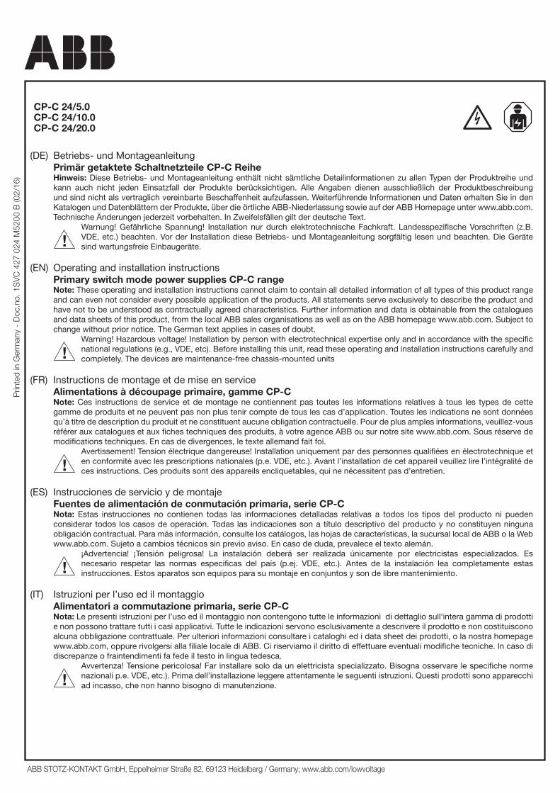
CP-C 24/5.0CP-C 24/10.0CP-C 24/20.0
(DE) Betriebs- und Montageanleitung Primär getaktete Schaltnetzteile CP-C Reihe
Hinweis: Diese Betriebs- und Montageanleitung enthält nicht sämtliche Detailinformationen zu allen Typen der Produktreihe und kann auch nicht jeden Einsatzfall der Produkte berücksichtigen. Alle Angaben dienen ausschließlich der Produktbeschreibung und sind nicht als vertraglich vereinbarte Beschaffenheit aufzufassen. Weiterführende Informationen und Daten erhalten Sie in den Katalogen und Datenblättern der Produkte, über die örtliche ABB-Niederlassung sowie auf der ABB Homepage unter www.abb.com. Technische Änderungen jederzeit vorbehalten. In Zweifelsfällen gilt der deutsche Text.
Warnung! Gefährliche Spannung! Installation nur durch elektrotechnische Fachkraft. Landesspezifische Vorschriften (z.B. VDE, etc.) beachten. Vor der Installation diese Betriebs- und Montageanleitung sorgfältig lesen und beachten. Die Geräte sind wartungsfreie Einbaugeräte.
(EN) Operating and installation instructions Primary switch mode power supplies CP-C range
Note: These operating and installation instructions cannot claim to contain all detailed information of all types of this product range and can even not consider every possible application of the products. All statements serve exclusively to describe the product and have not to be understood as contractually agreed characteristics. Further information and data is obtainable from the catalogues and data sheets of this product, from the local ABB sales organisations as well as on the ABB homepage www.abb.com. Subject to change without prior notice. The German text applies in cases of doubt.
Warning! Hazardous voltage! Installation by person with electrotechnical expertise only and in accordance with the specific national regulations (e.g., VDE, etc). Before installing this unit, read these operating and installation instructions carefully and completely. The devices are maintenance-free chassis-mounted units
(FR) Instructions de montage et de mise en service Alimentations à découpage primaire, gamme CP-C
Note: Ces instructions de service et de montage ne contiennent pas toutes les informations relatives à tous les types de cette gamme de produits et ne peuvent pas non plus tenir compte de tous les cas d’application. Toutes les indications ne sont données qu’à titre de description du produit et ne constituent aucune obligation contractuelle. Pour de plus amples informations, veuillez-vous référer aux catalogues et aux fiches techniques des produits, à votre agence ABB ou sur notre site www.abb.com. Sous réserve de modifications techniques. En cas de divergences, le texte allemand fait foi.
Avertissement! Tension électrique dangereuse! Installation uniquement par des personnes qualifiées en électrotechnique et en conformité avec les prescriptions nationales (p.e. VDE, etc.). Avant l’installation de cet appareil veuillez lire l’intégralité de ces instructions. Ces produits sont des appareils encliquetables, qui ne nécessitent pas d’entretien.
(ES) Instrucciones de servicio y de montaje Fuentes de alimentación de conmutación primaria, serie CP-C
Nota: Estas instrucciones no contienen todas las informaciones detalladas relativas a todos los tipos del producto ni pueden considerar todos los casos de operación. Todas las indicaciones son a título descriptivo del producto y no constituyen ninguna obligación contractual. Para más información, consulte los catálogos, las hojas de características, la sucursal local de ABB o la Web www.abb.com. Sujeto a cambios técnicos sin previo aviso. En caso de duda, prevalece el texto alemán.
¡Advertencia! ¡Tensión peligrosa! La instalación deberá ser realizada únicamente por electricistas especializados. Es necesario respetar las normas especificas del país (p.ej. VDE, etc.). Antes de la instalación lea completamente estas instrucciones. Estos aparatos son equipos para su montaje en conjuntos y son de libre mantenimiento.
(IT) Istruzioni per l’uso ed il montaggio Alimentatori a commutazione primaria, serie CP-C
Nota: Le presenti istruzioni per l’uso ed il montaggio non contengono tutte le informazioni di dettaglio sull‘intera gamma di prodotti e non possono trattare tutti i casi applicativi. Tutte le indicazioni servono esclusivamente a descrivere il prodotto e non costituiscono alcuna obbligazione contrattuale. Per ulteriori informazioni consultare i cataloghi ed i data sheet dei prodotti, o la nostra homepage www.abb.com, oppure rivolgersi alla filiale locale di ABB. Ci riserviamo il diritto di effettuare eventuali modifiche tecniche. In caso di discrepanze o fraintendimenti fa fede il testo in lingua tedesca.
Avvertenza! Tensione pericolosa! Far installare solo da un elettricista specializzato. Bisogna osservare le specifiche norme nazionali p.e. VDE, etc.). Prima dell’installazione leggere attentamente le seguenti istruzioni. Questi prodotti sono apparecchi ad incasso, che non hanno bisogno di manutenzione.
ABB STOTZ-KONTAKT GmbH, Eppelheimer Straße 82, 69123 Heidelberg / Germany; www.abb.com/lowvoltage
(RU) Инструкция по установке и эксплуатации Первичные импульсные источники электропитания серии CP�C
Примечание: Настоящая инструкция по установке и эксплуатации не претендует на полноту содержащейся здесь информации по всем типам изделий серии и не рассматривает все возможности применения настоящего изделия. Вся информация служит исключительно для его описания и не должна рассматриваться в качестве гарантированных характеристик, имеющих юридическую силу. Дополнительную информацию и данные можно получить из каталогов и листа тех. данных на настоящее изделие в местном представительстве компании АВВ, а также на сайте компании АВВ по адресу: www.abb.com. Возможны изменения без предварительного уведомления. При возникновении сомнений текст на немецком языке имеет приоритет.
Oсторожно! Опасное напряжение! Монтаж должен выполняться только специалистом-электриком в соответствии с нормативным законодательством (т.к. VDE, итд). Перед установкой элемента внимательно ознакомьтесь с инструкцией. После установки и настройки блок не требует обслуживания.
(ZH) CP-C
ABB ABB www.abb.com
VDE
Additional information relating to cULs approval: Power, input and output (I/O) wiring must be in accordance with Class I, Div. 2 wiring methods - Article 501-10(B) (1) of the National Electrical Code.- SUITABLE FOR USE IN CLASS I, DIVISION 2, GROUPS A, B, C, D OR NON-HAZARDOUS LOCATIONS ONLY. - WARNING - EXPLOSION HAZARD - SUBSTITUTION OF COMPONENTS MAY IMPAIR SUITABILITY FOR CLASS I, DIVISION 2.- WARNING - EXPLOSION HAZARD - DO NOT DISCONNECT EQUIPMENT UNLESS POWER HAS BEEN SWITCHED OFF OR THE AREA IS KNOWN TO BE NON-HAZARDOUS. Units are for indoor use only. Units can be used up to an altitude of max 2000 m. Units are for “overvoltage category II” (mains supply).
Information complémentaire relative à la certification cULus: Le câblage de puissance et des entrées/sorties doit être conforme aux méthodes de câblage de la classe I, div. 2 – article 501-10 (B) (1) du National Electrical Code.- POUR UTILISATION SELON LA CLASSE I, DIVISION 2, GROUPES A, B, C, D OUR ENVIRONMENTS NON DANGEREUX.- AVERTISSEMENT - RISQUE D’EXPLOSION – LA SUBSTITUTION DE COMPOSANTS PEUT NUIRE À LA CONFORMITÉ CLASSE I, DIVISION 2.- AVERTISSEMENT - RISQUE D’EXPLOSION - NE PAS DÉBRANCHER UN COMPOSANT AVANT D’AVOIR COUPÉ L’ALIMENTATION OU D’ÊTRE EN PRÉSENCE D’UNE ZONE NON DANGEREUSELes unités sont pour un usage intérieur. Les unités peuvent être utilisées jusqu’à une altitude maximale de 2000 m. Les unités sont pour “la catégorie de surtension II” (alimentation principale).
2
2CD
C 2
72 0
13 F
0b04
2CD
C 2
72 0
12 F
0b04
56,5 2.22”
135.
55.
35”
130
5.12
”
(A)
(A)
(B)
(B)
1
2CD
C 2
72 0
01 F
0b09
90 3.54”
(A)
(B)
(A)
(B)
1
135.
55.
35”
130
5.12
” 2CD
C 2
72 0
02 F
0b09
130
5.12
”
200 7.87”
135.
55.
35”
(A)
(B)
(B)
1
2CD
C 2
72 0
03 F
0b09
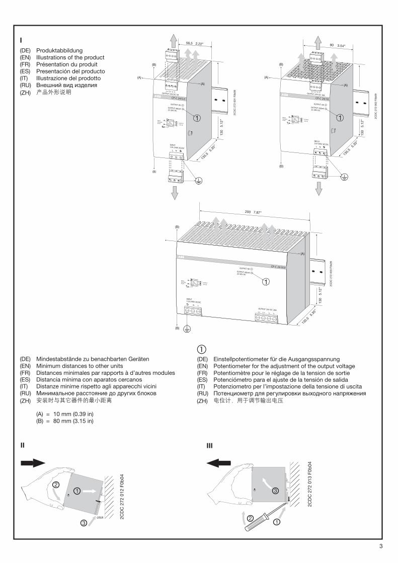
(DE) Mindestabstände zu benachbarten Geräten(EN) Minimum distances to other units(FR) Distances minimales par rapports à d’autres modules(ES) Distancia mínima con aparatos cercanos(IT) Distanze minime rispetto agli apparecchi vicini(RU) Минимальное расстояние до других блоков(ZH)
(A) = 10 mm (0.39 in)(B) = 80 mm (3.15 in)
�(DE) Einstellpotentiometer für die Ausgangsspannung(EN) Potentiometer for the adjustment of the output voltage(FR) Potentiomètre pour le réglage de la tension de sortie(ES) Potenciómetro para el ajuste de la tensión de salida(IT) Potenziometro per l’impostazione della tensione di uscita(RU) Потенциометр для регулировки выходного напряжения(ZH)
I
(DE) Produktabbildung(EN) Illustrations of the product(FR) Présentation du produit(ES) Presentación del producto(IT) Illustrazione del prodotto(RU) Внешний вид изделия(ZH)
II III
3
CP
-C 2
4/5
.0C
P-C
24/1
0.0
CP
-C 2
4/2
0.0
Uout [V]
Iout [A]
2CD
C 2
72 0
26 F
0b04
Uout [V]
Iout [A]
2CD
C 2
72 0
27 F
0b04
Uout [V]
Iout [A]
2CD
C 2
72 0
28 F
0b04
Iout [A]
Ta [°C]
2C
DC
27
2 0
06
F0
20
4
Iout [A]
Ta [°C]
2CD
C 2
72 0
75 F
0204
Iout [A]
Ta [°C]
2CD
C 2
72 0
88 F
0204
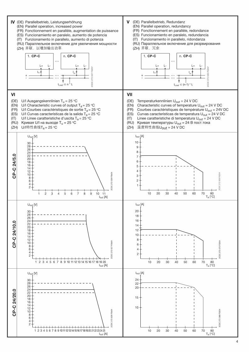
IV (DE) Parallelbetrieb, Leistungserhöhung(EN) Parallel operation, increased power(FR) Fonctionnement en parallèle, augmentation de puissance(ES) Funcionamiento en paralelo, aumento de potencia(IT) Funzionamento in parallelo, aumento di potenza(RU) Параллельное включение для увеличения мощности(ZH)
CP-C 1. n. CP-C
L+ L+ L- L-
Ir1 Irn
2C
DC
27
2 0
37
F0
20
7
ILoad � n * Ir
V (DE) Parallelbetrieb, Redundanz(EN) Parallel operation, redundancy(FR) Fonctionnement en parallèle, redondance(ES) Funcionamiento en paralelo, redundancia(IT) Funzionamento in parallelo, ridondanza(RU) Параллельное включение для резрвирования(ZH)
CP-C1. n. CP-C
L+ L+ L- L-
Ir1 Irn
2C
DC
27
2 0
35
F0
20
7
ILoad � (n-1) * Ir
VI
(DE) U/I Ausgangskennlinien Tu = 25 oC(EN) U/I Characteristic curves of output Ta = 25 oC(FR) U/I Courbes caractéristiques de sortie Ta = 25 oC(ES) U/I Curvas características de la salida Ta = 25 oC(IT) U/I Linee caratteristiche d’uscita Ta = 25 oC(RU) Кривая U/I на выходе Tu = 25 oC(ZH) U/I Ta = 25 oC
VII
(DE) Temperaturkennlinien Uout = 24 V DC(EN) Characteristic curves of temperature Uout = 24 V DC(FR) Courbes caractéristiques de température Uout = 24V DC(ES) Curvas características de temperatura Uout = 24 V DC(IT) Linee caratteristiche di temperatura Uout = 24 V DC(RU) Кривая температуры Uout = 24 В пост.тока(ZH) Uout = 24 V DC
4
(DE) Sicherheits- und Warnhinweise
Anlage freischalten! Vor Installations-, Wartungs- oder Änderungsarbeiten: Anlage spannungsfrei schalten, vor Wiedereinschalten sichern.
Vor Inbetriebnahme: Achtung! Unsachgemäße Installation/Betrieb kann die Sicherheit beeinträchtigen und zu Betriebsstörungen oder zur Zerstörung des Gerätes führen. Vor der Inbetriebnahme ist Folgendes sicherzustellen:• Netzanschluss gemäß den landesspezifischen Vorschriften für Schutzklasse I durchführen• Zuleitungen und Gerät ausreichend absichern. Eine Trenneinrichtung für das Netzteil vorsehen, um das Gerät und
die Zuleitungen im Bedarfsfall zu unterbrechen• Schutzleiter an die Klemme o (siehe Abbildung I) anschließen• Ausgangsleitungen für den Ausgangsstrom des Netzteils dimensionieren und polrichtig anschließen.• Abstände zu benachbarten Geräten beachten (siehe Abbildung I) um eine ausreichende Kühlung zu gewährleisten• Schrauben am Gehäuse dienen der geräteinternen Erdung. Nicht entfernen! Keine Kabel anschließen!
Im Betrieb:
• Keinerlei Änderungen an der Installation (primär- und sekundärseitig) vornehmen! (Starkstrom!). Gefahr von Lichtbögen und elektrischem Schlag (Lebensgefahr)!
• Bei CP-C 24/5.0 und CP-C 24/10.0 Steckverbinder nur leistungslos betätigen!• Verbrennungsgefahr: In Abhängigkeit der Betriebsbedingungen kann die Gehäusetemperatur hohe Werte annehmen. • Löst die interne Sicherung aus, liegt mit hoher Wahrscheinlichkeit ein Gerätedefekt vor. In diesem Fall ist eine
Überprüfung des Schaltnetzteils durch den Hersteller erforderlich.
Achtung: Hochspannung! Gespeicherte Energie! Gefährliche Energie am Ausgang!
In den Netzteilen befinden sich Bauelemente mit hoher gespeicherter Energie und Stromkreise mit Hochspannung! Deshalb keine Gegenstände in das Gerät einführen und das Gerät nicht öffnen. Bei einigen Geräten dieser Serie kann der Ausgang gefährlich hohe Energiemengen abgeben. Sicherstellen, dass Bedienpersonal vor versehentlicher Berührung energieführender Teile geschützt ist.
(EN) Safety instructions and warnings
Disconnect system from supply network!
Before any installation, maintenance or modification work: Disconnect the system from the supply network and protect against switching on.
Before start of operation:
Attention! Improper installation/operation may impair safety and cause operational difficulties or destruction of the unit. Before operation the following must be ensured:• Connect to main according to the specific national regulations for class of protection I.• Power supply cables and unit must be sufficiently fused. A disconnecting device has to be provided for the end
product to disengage unit and supply cables from supply mains if required. • The protective earth conductor must be connected to the terminal o (see figure I) • Rate the output lines for the output current of the power supply and connect them with the correct polarity. • In order to ensure sufficient air-cooling the distance to other devices has to be considered (see figure I) • Screws at the enclosure are for internal grounding. Do not remove them! Do not connect cables!
In operation:
• Do not modify the installation (primary and secondary side)! High current! Risk of electric arcs and electric shock (danger to life)!
• (Dis)connect the plug connector of CP-C 24/5.0 and CP-C 24/10.0 only when the power is off! • Risk of burns: Depending on the operation conditions the enclosure can become very hot • If the internal fuse blows, most probably the device is defective. In this case, an examination of the switch mode
power supply by the manufacturer is necessary.
Warning: High voltage! Stored energy! Energy hazard at output!
The power supplies contain components with high stored energy and circuits with high voltage! Do not introduce any objects into the unit, and do not open the unit. With some units of this range the output is capable of providinghazardous energy. Ensure that the service personnel is protected against inadvertent contact with parts carrying energy.
(FR) Indications de sécurité et mises en garde
Mettre l’installation hors tension!
Avant le début des travaux d’installation, d’entretien ou de modification : mettre le module hors tension et s’assurer qu’il ne peut pas être remis sous tension par erreur.
Avant la mise en service: Attention! Une installation non adaptée peut diminuer la sécurité, provoquer des disfonctionnements et amener la destruction du module. Avant la mise en service il faut veiller aux points suivants :• Le raccordement au réseau doit être effectué en conformité avec les prescriptions appliquées dans le pays
concerné pour la classe de protection I• Protéger suffisamment les câbles et le module. Un dispositif de coupure doit être prévu en tête de l’appareil de
manière à ce qu’il soit isolé des câbles d’alimentation si besoin. • Raccorder le fil de protection à la borne o (voir Fig. I).• Tous les câbles de sortie doivent être dimensionnés pour le courant de sortie et raccordés correctement par
rapport à la polarité.• Considérer la distance du module aux autres modules (voir Fig. I) pour garantir un refroidissement suffisant.• Les vis du boîtier servent à la mise à la terre interne. Ne pas les retirer ! Ne pas les utiliser pour raccorder des câbles!
5
Sous tension:
• Ne pas effectuer de changements (côté primaire et secondaire) quand le module est sous tension! (Courant fort!). Risque de formation d’arcs et de chocs électriques (danger de mort!)
• Ne manipuler le connecteur multiple des modules CP-C 24/5.0 et CP-C 24/10.0 qu’ uniquement hors tension! • Risques de brûlures: Selon les conditions d’utilisation le boîtier peut devenir très chaud. • Si le fusible interne fond, selon toute probabilité l’appareil est défectueux. Dans ce cas il faut faire examiner
l’alimentation à découpage par le producteur.
Attention: Haute tension! Energie emmagasinée! Energie dangereuse à la sortie!
Le module renferme des composants emmagasinant de l’énergie et des circuits sous haute tension! Ne pas introduire d’objets dans le module et ne pas l’ouvrir! La sortie de certains appareils peut émettre d’importantes quantités d’énergie. Il faut s’assurer que le personnel de maintenance soit protegé contre les contacts accidentels avec des composants sous tension.
(ES) Avisos de seguridad S
Desconecte la instalación! Antes de iniciar trabajos de instalación, mantenimiento o modificación desconecte su instalación y cerciórese de que no pueda ser conectada nuevamente por descuido.
Antes de la puesta en marcha:
Atención! Una instalación incorrecta o uso inadecuado puede afectar a la seguridad y al funcionamiento, hasta la destrucción total del aparato. Hay que comprobar lo siguiente antes de la puesta en marcha:• La conexión debe hacerse conforme a las disposiciones nacionales aplicables para la clase de protección I.• Proteger adecuadamente el aparato y los cables de alimentación. Con la intención de proteger, se debe colocar
un dispositivo de aislamiento en el equipo final de modo que, en caso necesario, quede interrumpido el paso de corriente al equipo y las líneas de alimentación
• Conectar el conductor de protección al borne o (ver Fig. I)• Todos los cables de salida deben ser adecuados para la intensidad de salida del bloque de alimentación y
conectados con polarización correcta.• Tener en cuenta la distancia con aparatos cercanos (ver Fig. I) para garantizar una refrigeración suficiente. • Los tornillos en la caja sirven para la puesta a tierra interior. No quitar! No conectar cables!
Durante el funcionamiento:
• En ningún caso efectuar modificaciones de la instalación (lado primario y secundario)! Corriente de alta tensión! Peligro de arcos voltáicos y choques eléctricos (peligro de muerte)!
• Los conectores enchufables de los aparatos CP-C 24/5.0 y CP-C 24/10.0 sólo deben manipularse si no tienen corriente!• Peligro de quemaduras: Dependiendo de las condiciones de funcionamiento, la caja puede alcanzar temperaturas elevadas.• Si el fusible interno se funde, lo más probable es que el aparato esté defectuoso. En este caso, es necesario que
el fabricante examine la fuente de alimentación conmutada.
Atención: Alta tensión! Energía acumulada! Riesgo de energía en los terminales de salida!
El aparato contiene conductores no protegidos bajo alta tensión, así como componentes que acumulan energía elevada! No introducir objetos en el aparato y no abrir. En algunos dispositivos de esta serie, la salida puede emitir intensidades de energía peligrosas. Es necesario la protección del personal de servicio, para evitar contactos accidentales.
(IT) Norme di sicurezza e avvertenze
Disinserire il sistema!
Prima di eseguire lavori di installazione, manutenzione o modifica, disinserire il sistema, assicurarsi che sia privo di tensione e che non possa essere reinserita inavvertitamente.
Prima della messa in funzione:
Attenzione! La scorretta installazione e il funzionamento inadeguato possono pregiudicare la sicurezza e portare a guasti e al danneggiamento del dispositivo. Prima della messa in funzione bisogna accertarsi del seguente:• Il collegamento alla rete deve essere conforme alle specifiche norme nazionali riguardo la classe di protezione I• L’apparecchio e i cavi d’alimentazione devono essere sicuri in modo sufficiente. Si deve prevedere un dispositivo di seziona-
mento per il terminale, in modo da poter interrompere, in caso di necessità, sia l’apparecchio che le linee di alimentazione. • Collegare il conduttore di terra al morsetto o (vedere Fig. I)• Dimensionare tutti i cavi d’uscita idoneamente e collegarli con giusta polarità. • Badare alle distanze verso apparecchi vicini (vedere Fig. I) per garantire un sufficiente raffredamento.• Le viti poste sulla custodia servono per il collegamento a terra interno. Non togliere le viti! Non collegare cavi!
Durante il funzionamento:
• Non apportare modifiche all’installazione (parte primaria e secondaria)! Corrente ad alta tensione! Pericolo di arco voltaico e shock di corrente (Pericolo di morte)!
• Azionare il connettore a spina degli apparecchi CP-C 24/5.0 e CP-C 24/10.0 senza potenza!• Pericolo di ustioni: A seconda delle condizioni di funzionamento, la custodia può diventare molto calda. • Se il fusibile interno scatta, molto probabilmente l’apparecchio è difettoso. In questo caso bisogna far
esaminare l’alimentatore a commutazione dal produttore.
Attenzione: Alta tensione! Energia accumulata! Energia pericolosa all’uscita!
Gli alimentatori sono provvisti di componenti che accumulano moltissima energia, nonché di conduttori non protetti ad alta tensione! Perciò non introdurre oggetti nell’apparecchio e non aprire l’apparecchio. In alcuni apparecchi di questa serie l’uscita può emettere pericolosamente elevati quantitativi di energia. Provvedere alla adeguate protezione del personale di manutenzione contro eventuali contatti fortuiti con componenti portando energia.
6
(RU) Инструкции по технике безопасности и предупреждения
Отключите систему от источника питания!До выполнения работ по установке, техническому обслуживанию и изменению конструкции: необходимо отсоединить систему от источника питания и обеспечить ее защиту от повторного включения.
Перед началом работы:Внимание! Неправильная установка/эксплуатация может повлиять на безопасность персонала и стать причиной возникновения эксплуатационных трудностей или поломки установки. Перед работой необходимо обеспечить следующее:• Подключить к сети питания в соответствии с конкретными государственными нормативными требованиями к классу
защиты I.• Кабели и установка должны быть оснащены достаточным количеством плавких предохранителей. Для конечного
изделия, при необходимости, должно быть предусмотрено устройство для отключения установки и кабелей от источника питания.
• Провод защитного заземления должен быть подключен к клемме o (см. рис. I).• Установите в выходных линиях номинальное значение выходного тока устройства и подключите их с соблюдением
полярности. • С целью обеспечения достаточного охлаждения воздуха необходимо предусмотреть соответствующее расстояние
до других устройств (см. рис. I) • Винты в корпусе предназначены для внутреннего заземления. Не выкручивайте их! Не подключайте кабели!
При эксплуатации:• Не изменяйте конструкцию установки (основная и вторичная сторона)! Высокая сила тока! Опасность образования
электрической дуги и поражения электрическим током (опасно для жизни)!• Отключать/Включать разъем CP-C 24/5.0 и CP-C 24/10.0 можно только после снятия напряжения питания • Опасность ожогов: В зависимости от условий эксплуатации корпус может сильно нагреваться • Если перегорает плавкий предохранитель, то наиболее вероятно, что устройство неисправно. В этом случае
необходимо проведение экспертизы устройства производителем.
Внимание! Высокое напряжение! Накопленная электроэнергия! Опасность поражения электрическим током на выходе!В устройстве содержатся компоненты, в которых присутствует накопленная электроэнергия, и контуры с высоким напряжением! Запрещается вставлять предметы в устройство и открывать установку. В некоторых устройствах данного типоряда существует опасность поражения электрическим током на выходе. Обеспечьте защиту обслуживающего персонала от случайного соприкосновения с токоведущими деталями.
(ZH)
• I• • o Fig. I• • Fig. I•
• • CP-C 24/5.0 CP-C 24/10.0• •
7
(DE) Montage:
1. DIN-Schiene (TH 35-15 oder TH 35-7.5 nach IEC/EN 60715) wie in Abbildung I dargestellt auf der Montageplatte befestigen, horizontale Einbaulage, Eingangsklemmen unten, die Mindestabstände (siehe Abbildung I) zu benachbarten Geräten einhalten.
2. Gerät wie in Abbildung II dargestellt auf die DIN-Schiene aufschnappen. 1) Gerät leicht nach oben kippen und auf DIN-Schiene aufsetzen. 2) Bis zum Anschlag nach unten klappen. 3) Unten gegen die Vorderseite drücken, um zu verriegeln.
Leicht am Gerät rütteln, um Verriegelung zu überprüfen.
3. Entfernen von der DIN-Schiene wie in Abbildung III dargestellt. Schraubendreher zur Entriegelung verwenden.
Elektrischer Anschluss:
Eingangsseite [L, N, o ]Elektrische Verbindung der Eingangsklemmen L, N, o (Abbildung I) herstellen. Leitungsquerschnitte, Abisolierlänge der Leitungen, Anschlussdrehmomente etc. - siehe technische Daten. Schutzleiter muss immer angeklemmt werden (Schutzklasse I). Steckverbinder (CP-C 24/5.0, CP-C 24/10.0) nur leistungslos betätigen. Die Installation muss gemäß EN 60950 erfolgen, geeignete Trennvorrichtung (z.B. Leitungsschutzschalter) in den Zuleitungen vorsehen. Absicherung der Eingangsseite - siehe Technische Daten.
Ausgangsseite [L+, L+, L-, L-]
Leitungen nach maximalem Ausgangsstrom dimensionieren oder gesonderte Absicherung vorsehen. Absicherung der Ausgangsseite - siehe Technische Daten. Um Spannungsabfälle zu minimieren wird empfohlen die Querschnitte so groß wie möglich zu wählen. Polung beachten. Steckverbinder (CP-C 24/5.0, CP-C 24/10.0) nur leistungslos betätigen. Die Netzteile sind überlast-, kurzschluss- und leerlauffest (siehe Kennlinien). Die Sekundärseite der Netzteile ist galvanisch vom Eingang getrennt und intern nicht geerdet (SELV). Sie kann daher je nach Bedarf (wahlweise L+ oder L-) vom Anwender geerdet werden (PELV).
Betrieb/Funktion:
Betriebszustandsanzeige:
Die grüne LED „OUTPUT OK“ (Abbildung I) leuchtet bei Betrieb
Einstellung der Ausgangsspannung:
Am Potentiometer “OUTPUT Adjust” kann die Ausgangsspannung im Bereich von 22-28 V eingestellt werden.
Parallelbetrieb:
Typgleiche Geräte können zur Leistungserhöhung oder zu Redundanzzwecken parallel geschaltet werden. Für eine symmetrische Stromaufteilung wird empfohlen die Leitungsverbindungen in gleichen Querschnitt und ingleicher Länge auszuführen.
Parallelbetrieb, Leistungserhöhung: (siehe Abbildung IV) Bei n parallel geschalteten Netzteilen kann der Ausgangsstrom auf n x Ir erhöht werden. Wenn eine Stromversorgung den Strombedarf des leistungsstärksten Verbrauchers nicht abdeckt, wird eine Parallelschaltung zur Leistungserhöhung empfohlen. Es können bis zu 5 Geräte gleichen Typs parallel geschaltet werden. Ohne Parallelbetrieb zur Leistungserhöhung empfiehlt es sich, die Verbraucher mit voneinander unabhängigen Stromversorgungen zu speisen.
Parallelbetrieb, Redundanz: (siehe Abbildung V) Um bei Fehlern (z.B. in der Verdrahtung, Auslösen der Sicherung im Primärstromkreis, Defekt einzelner Geräte) eine höhere Verfügbarkeit zu erreichen, können Stromversorgungen redundant aufgebaut werden. Tritt im ersten Stromversorgungskreis ein Fehler auf (sog. Erstfehler), wird die Stromversorgung aller Verbraucher vom zweiten, redundanten Versorgungskreis übernommen. Hierzu werden die parallel zu schaltenden Stromversorgungen so dimensioniert, dass der Gesamtstrombedarf aller angeschlossenen Verbraucher von einer Stromversorgung vollständig abgedeckt werden kann.
Steckbares Funktionsmodul:
Frontseitig lässt sich optional das Meldemodul CP-C MM aufstecken. Dafür ist die Frontfolie leicht vorgeprägt.
8
(GB) Mounting:
1. Fasten the DIN rail (TH 35-15 or TH 35-7.5 acc. IEC/EN 60715) as shown in Fig. I on the mounting plate, horizontal mounting position, input terminals on bottom, respect the minimum distance to other units (see Fig. I)
2. Snap on DIN rail as shown in Fig. II1) Tilt the unit slightly upwards and fit the unit on the DIN rail2) Lift it downward until it hits the stop 3) Press against the bottom front side for locking Shake the unit slightly to check the locking
3. Remove the unit from the DIN rail as shown in Fig. III. Use a screwdriver for the unlocking.
Electrical connection:
Input side [L, N, o ]Connect the input terminals L, N, o (Fig. I ). Cable cross sections, stripping length of the cable, tightening torque etc. - see technical data. The protective earth conductor must be connected (class of protection I). Actuate the plug connector (CP-C 24/5.0, CP-C 24/10.0) only when the power is off. The installation must be executed acc. EN 60950, provide a suitable disconnecting device (e.g., line protection switch) in the supply line. Fuse protection of the input side - see technical data.
Output side [L+, L+, L-, L-]
Rate the lines for the maximum output current or provide a separate fuse protection. Fuse protection of the output side - see technical data. We recommend choosing the cable cross section as large as possible in order to minimize voltage drops. Observe the polarity. Actuate the plug connector (CP-C 24/5.0, CP-C 24/10.0) only when the power is off. The power supplies are overload, short-circuit and no-load proof (see characteristic curve). The secondary side of the power supplies is electrically isolated from the input and internally not earthed (SELV) and can therefore be earthed by the user according to the needs with L+ or L- (PELV).
Operating/Function:
Operational status indication:
The green LED „OUTPUT OK“ (Fig. I) is lightening during operation.
Adjustment of the output voltage:
The output voltage can be adjusted in the range of 22 to 28 V by means of the potentiometer “OUTPUT Adjust”.
Parallel operation:
In order to increase power and to enable redundancy, devices of the same type can be connected in parallel. For a symmetric current distribution it is advisable to execute the line connections with the same cross sections and same lengths.
Parallel operation, increased power: (see Fig. IV)For n parallel connected devices, the output current can be increased to n x Ir . If a power supply unit can not handle the current requirement of the most powerful load, it is advisable to increase power by parallel connected power supplies. Otherwise the loads should be spread among individual devices independent of one another. A maximum of 5 devices of the same type can be connected in parallel.
Parallel operation, redundancy: (see Fig. V) Redundant circuits are used to increase the operational reliability in case of errors (e.g., wrong wiring, blow of the fuses in the primary circuit, failure of single devices). If a fault occurs in the first power supply circuit (called initial fault), power to all loads is then supplied by the second, redundant supply circuit. For this reason the power supply units to be connected in parallel must be sized in such a way that the total current requirement of all loads can be completely covered by one power supply unit.
Pluggable function module:
As an option, the messaging module CP-C MM can be attached to the front side. For this purpose the front foil is slightly pre-cut.
9
(FR) Montage:
1. Fixer le profilé DIN (TH 35-15 ou TH 35-7.5 selon IEC/EN 60715) sur la platine de montage comme décrit dans la Fig. I, position de montage horizontale, bornes d’entrée en bas, observer les distances minimales (voir Fig. I) par rapports à d’autres modules.
2. Encliqueter le module sur le profilé DIN comme décrit dans la Fig. II 1) Basculer le module légèrement vers le haut et le placer sur le profilé2) Pousser vers le bas jusqu’à la butée3) Pousser vers l’avant pour encliqueter
Secouer légèrement pour vérifier l’encliquetage
3. Démonter du profilé DIN comme décrit dans la Fig. III. Utiliser un tournevis pour le désencliquetage.
Raccordement électrique:
Entrée [L, N, o ]Raccorder les bornes d’entrée L, N, o (Fig. I ). Sections de câble, longueur des câbles à dénuder, couple de serrage, etc. – voir Données Techniques. Le fil de protection doit toujours être raccordé (classe de protection I). Manipuler le connecteur multiple (CP-C 24/5.0, CP-C 24/10.0) uniquement hors tension. L’installation doit être exécutée conformément à la directive EN 60950, prévoir un dispositif de coupure approprié (ex : disjoncteur de protection) dans les câbles d’alimentation. Protection de l’entrée - voir Données Techniques.
Sortie [L+, L+, L-, L-]
Dimensionner les lignes pour le courant de sortie maximum ou les protéger par un fusible spécial. Protection de la sortie - voir Données Techniques. Choisir des câbles de grande section, afin de réduire au minimum les chutes de tension. Faire attention à la polarité. Manipuler le connecteur multiple (CP-C 24/5.0, CP-C 24/10.0) uniquement hors tension. Le module est doté d’une protection électronique contre les surcharges, les courts-circuits et la marche à vide (voir courbes caractéristiques). Le côté secondaire des alimentations est isolé électriquement de l’entrée et en interne de la terre (SELV). Pour cette raison, l’utilisateur peut mettre facultativement L+ ou L- à la terre, selon les besoins (PELV).
Opération/Fonctionnement:
Indications de fonctionnement:
La LED verte „OUTPUT OK“ (Fig. I) s’allume en fonctionnement.
Réglage de la tension de sortie:
La tension de sortie peut être réglée dans la gamme de 22 à 28 V avec le potentiomètre “OUTPUT Adjust”.
Fonctionnement en parallèle:
Des modules de même type peuvent être branchés en parallèle pour augmenter la puissance ou pour réaliser un circuit redondant. Pour une répartition symétrique du courant, nous conseillons de réaliser toutes les liaisons de l’alimentations avec la même longueur et la même section de câble.
Fonctionnement en parallèle, augmentation de puissance: (voir Fig. IV)Avec n modules branchés en parallèle, le courant de sortie peut être augmenté jusqu’à n x Ir . Lorsque l’alimentation ne couvre pas la demande en courant du consommateur le plus puissant, le montage en parallèle est recommandé pour augmenter la puissance. On peut brancher en parallèle jusqu’à 5 modules. Sans montage en parallèle, il faut répartir les appareils sur différents modules indépendant les uns des autres.
Fonctionnement en parallèle, redondance: (voir Fig. V) Pour arriver à une fiabilité de fonctionnement plus élevée en cas d’erreurs (p.e. en câblage, déclenchement du fusible dans le circuit primaire, défaut d’un module unique), on peut monter des circuits redondants. En cas de défaut dans le circuit primaire de la première alimentation (dit premier erreur), le second module redondant prend le relais pour assurer l’alimentation de tous les consommateurs. Pour cela, les alimentations à brancher en parallèle doivent être dimensionnées de manière à ce qu’un seul module puisse couvrir intégralement la demande totale en courant de tous les appareils consommateurs.
Module de fonction enfichable:
Comme option, le module de signalisation CP-C MM peut être enfiché sur la face avant. Pour cela, la feuille frontale est déjà légèrement perforée.
10
(ES) Montaje
1. Fijación del perfil DIN (TH 35-15 ó TH 35-7.5 según IEC/EN 60715) sobre una placa de montaje como se muestra en la Fig. 1, montaje en posición horizontal, los terminales de entrada deben de estar hacía abajo, tener en cuenta la distancia mínima con aparatos cercanos (ver Fig. I)
2. Fijación del aparato en el perfil como se muestra en la Fig. II 1) Posicionar el aparato en el perfil, encajar la parte superior de fijación en el perfil 2) Desplazar el aparato hacía abajo para su colocación en el perfil3) Presionar sobre la cubierta para su fijación. Mover ligeramente el aparato para comprobar su enclavamiento
3. Para desmontar el aparato se utiliza un destornillador como se muestra en la Fig. III.
Conexión eléctrica:
Entrada [L, N, o ]Conectar los terminales de entrada L, N, o (Fig. I). Secciones de cable, longitud a pelar del conductor, par de apriete, etc. - ver Datos Técnicos. El conductor de protección debe ser siempre conectado (clase de protección I). Accionar los conectores enchufables (CP-C 24/5.0, CP-C 24/10.0) solo en estado de apagado. La instalación tiene que realizarse conforme a las especificaciones EN 60950, preveer un dispositivo de aislamiento apropiado (p.ej. interruptores automáticos) en los cables de entrada. Entrada protegida por fusible- ver Datos Técnicos.
Salida [L+, L+, L-, L-]
Dimensionar los cables para la intensidad de salida máxima o preveer un fusible por separado. Protección por fusible de salida – ver Datos Técnicos. Los cables deben ser de la sección más grande posible para reducir la caída de tensión. Tener en cuenta la polarización. Accionar los conectores enchufables (CP-C 24/5.0, CP-C 24/10.0) solo en estado de apagado. Las fuentes de alimentación están protegidas contra sobrecarga, cortocircuito y circuito abierto (ver curvas de características). El lado secundario de la fuente de alimentación está aislado eléctricamente de la entrada y no está puesto a tierra internamente (SELV). Por ello se puede poner a tierra opcionalmente L+ o L- (PELV).
Servicio/Funcionamiento:
Indicador del estado de funcionamiento:
El LED verde „OUTPUT OK“ (Fig. I) se ilumina durante el funcionamiento.
Ajuste de la tensión de salida:
Mediante el potenciómetro “OUTPUT Adjust” la tensión de salida se puede ajustar en el margen de 22-28 V.
Funcionamiento en paralelo:
Los módulos de igual tipo pueden conectarse en paralelo para aumentar la potencia o para realizar un circuito redundante. Para obtener un reparto de corriente simétrico, recomendamos que las conexiones de los cables se realicen con igual sección e igual longitud.
Funcionamiento en paralelo, aumento de potencia: (ver Fig. IV) Para n módulos conectados en paralelo, la corriente de salida puede aumentarse a n x Ir . Cuando la fuente de alimentación no cubre el consumo de corriente del receptor más potente, se aconseja una conexión en paralelo para aumentar la potencia. En total pueden conectarse en paralelo 5 módulos de igual tipo.Sin conexión en paralelo, los receptores deben repartirse a módulos individuales, independientemente unos de otros.
Funcionamiento en paralelo, redundancia: (ver Fig. V) Los circuitos redundantes se utilizan para aumentar la seguridad de servicio en caída de un defecto (p.ej. cableado incorrecto, fusión de los fusibles en el circuito primario, fallo en el dispositivo). Si en la primaria fuente de alimentación se tiene un defecto (llamado primer defecto), el segundo, redundante circuito de alimentación adopta la alimentación de corriente de todos los receptores. A tal fin, las fuentes de alimentación a conectar en paralelo se dimensionan de forma, que el consumo de corriente total de todos los receptores conectados se pueda cubrir por completo por una sola fuente de alimentación.
Módulo de función enchufable:
Como opción, el módulo de señalización CP-C MM puede ser anadido en el lado frontal. Para eso la hoja frontal está ligeramente preperforada.
11
(IT) Montaggio:
1. Fissare la barra DIN (TH 35-15 o TH 35-7.5 in conformità con IEC/EN 60715) come descritto nella Fig. I sulla piastra di montaggio, montare in posizione orizzontale, morsetti d’ingresso in basso, osservare le distanze minime (vedere Fig. I) rispetto agli apparecchi vicini.
2. Applicare l’apparecchio come descritto nella Fig. II sulla guida di supporto 1) Tenere l’apparecchio leggermente inclinato verso l’alto, poggiarlo sul supporto sagomato2) Premere verso il basso fino alla battuta3) Spingere in avanti premendo in basso fino ad avvenuto arresto Verificarne la stabilità scrollandolo leggermente
3. Rimuovere l’apparecchio dalla guida di supporto come descritto nella Fig. III. Usare un cacciavite per lo sbloccaggio.
Collegamento elettrico:
Ingresso [L, N, o ]Collegare i morsetti d’ingresso L, N, o (Fig. I). Sezione della linea, lunghezza della spelatura, coppia di serraggio etc. - vedere Dati Tecnici. Il conduttore di terra deve essere sempre collegato (classe di protezione I). Azionare il connettore a spina (CP-C 24/5.0, CP-C 24/10.0) solo senza potenza. L’installazione deve essere eseguita in conformità con EN 60950, prevedere un addato dispositivo di sezionamento (p.e. interruttore automatico) per i cavi d’alimentazione. Protezione dell’ingresso - vedere Dati Tecnici.
Uscita [L+, L+, L-, L-]
Dimensionare le linee a secondo della corrente d’uscita massima oppure prevedere una protezione separata. Protezione dell’uscita - vedere Dati Tecnici. Per minimizzare cadute di tensione raccomandiamo di scegliere delle sezioni più grandi possibile. Considerare la polarità. Azionare il connettore a spina (CP-C 24/5.0, CP-C 24/10.0) solo senza potenza. Gli alimentatori sono protetti contro i sovraccarichi, i cortocircuiti e il funzionamento a vuoto (vedere linee caratteristiche). La parte secondaria degli alimentatori è isolata in corrente continua dall’ingresso e internamente non collegata a terra (SELV). Pertanto può essere collegata a terra, a scelta L+ o L- (PELV).
Operazione/Funzionamento:
Visualizzazione dello stato di funzionamento:
Il LED verde „OUTPUT OK“ (Fig. I) s’illumina durante l’operazione
Impostazione della tensione di uscita:
Tramite il potenziometro “OUTPUT Adjust” la tensione di uscita può essere impostata nel range da 22 a 28 V.
Funzionamento in parallelo:
Apparecchi dello stesso tipo possono essere collegati in parallelo per aumentare la potenza o per realizzare un circuito ridondante. Per ottenere una ripartizione di corrente simmetrica si raccomanda di realizzare tutti i collegamenti di linee con la stessa sezione e con la stessa lunghezza.
Funzionamento in parallelo, aumento di potenza: (vedere Fig. IV) Con n alimentatori collegati in parallelo, la corrente d’uscita può essere aumentata fino a n x Ir . Se l’alimentazione non copre il fabbisogno di corrente del più potente consumatore, è raccomandato un collegamento in parallelo. In totale si possono collegare in parallelo fino a 5 apparacchi dello stesso tipo. Senza collegamento in parallelo, si consiglia di alimentare i carichi con alimentatori indipendente uno dell’altro.
Funzionamento in parallelo, ridondanza: (vedere Fig. V)
Per aumentare l’affidabilità di funzionamento in caso di errori (p.e. di cablaggio, scatto del fusibile nel circuito di corrente primario, difetto di un apparecchio singolo), si può costruire un circuito di corrente ridondante. Se sorge un difetto nel primo circuito di alimentazione di corrente (cosiddetto primo errore), il secondo, ridondante circuito di alimentazione s’incarica dell’alimentazione di corrente di tutti i carichi. Perciò è necessario dimensionare gli alimentatori da collegare in parallelo in modo che il consumo di corrente totale di tutti i carichi collegati possa essere coperto completamente da un solo alimentatore.
Modulo funzionale a innesto:
Come opzione, sul lato frontale puo essere inserito il modulo di segnalazione CP-C MM. Per questo la foglia frontale è leggermente pre-perforata.
12
(RU) Монтаж:
1. Установите DIN рейку (TH 35-15 или TH 35-7,5 согласно стандарту IEC/EN 60715) как показано на Рисунке I, на монтажной панели в горизонтальном положении,входными клеммами вниз, сохраняя необходимое расстояние до других изделий (см. Рисунок I)
2. Установите изделие на DIN рейку как показано на Рисунке II1) Слегка наклоните изделие вверх и установите его на DIN рейку2) Потяните его вниз до упора3) Нажмите на нижний край лицевой панели для защелки. Слегка покачайте изделие,
чтобы убедиться в его надежном креплении
3. Демонтаж устройства с DIN рейки показан на Рисунке III. Для освобождения защелки используется отвертка.
Электрические соединения:
На стороне входа [L, N, o ]:Присоедините входные клеммы L, N, o (Рисунок 1), длина зачистки кабеля указана в технических характеристиках изделия.Проводник защитного заземления должен быть присоединен (класс защиты I).Подключать соединительный разъем CP-C 24/5.0 и CP-C 24/10.0 необходимо до подачи напряжения питания. Сечение кабелей и усилие затягивания клемм указаны в технических характеристиках изделия. Монтаж должен осуществляться в соответствии с требованиями EN 60950, с применением соответствующего размыкающего устройства (например, линейного защитного автомата) на стороне подачи электропитания.Защитные предохранители на входе – см. технические характеристики.
На стороне выхода [L+, L+, L�, L�]:Рассчитывайте номинальные параметры линий на максимальный выходной ток или используйте отдельные предохранители.Защитные предохранители на выходе – см. технические характеристики. Мы рекомендуем выбирать кабели с возможно большим сечением для минимизации потерь напряжения. Соблюдайте полярность.Подключать соединительный разъем CP-C 24/5.0 и CP-C 24/10.0 необходимо до подачи напряжения питания. Источники питания оборудованы средствами защиты от перегрузки, короткого замыкания и отсутствия нагрузки (см. характеристические кривые). Вторичный контур источников питания электрически изолирован от входного контура и внутри не заземлен (SELV), что позволяет заземлять его пользователем на линию L+ или LG (PELV), в зависимости от потребности
Эксплуатация/функционирование:
Индикаторы статуса работы:Зеленый СИД «OUTPUT OK» (рис. 1) сигнализирует о нормальной работе
Регулировка выходного напряжения:Выходное напряжение может регулироваться в диапазоне от 22 до 28 В с помощью потенциометра “OUTPUT adjust” (Регулировка выхода).
Параллельная работа: Для увеличения мощности и обеспечения резервирования изделия одного типа могут включаться параллельно. Для симметричного распределения тока рекомендуется подключать источники к линиям с одинаковым сечением и длиной проводов.В режиме параллельной работы блоков питания может загораться жёлтый СИД. В этом случае необходимо отрегулировать выходное напряжение потенциометром. Регулировка производить до тех пор, пока желтый СИД не погаснет.
Параллельная работа, увеличение мощности: (см. Рисунок IV)При параллельном соединении n изделий выходной ток может быть увеличен до n x IR.Рекомендуется использовать параллельное включение, если блок питания не может выполнить требования по отдаче тока, предъявляемые наиболее мощным потребителем. В ином случае, потребители должны подключаться к индивидуальным источникам независимо друг от друга.Параллельно можно соединить не более 5 устройств одного типа.
Параллельная работа, резервирование: (см. Рисунок V)Резервирование цепей используется для увеличения эксплуатационной надежности при возникновении ошибок (таких как неправильное включение, перегорание предохранителей в цепях первичного питания, авария отдельных устройств). Если неисправность возникает в цепи первого источника питания (так называемая первичная неисправность), электропитание всех потребителей будет осуществляться от второго, резервного, источника питания. По этой причине, параллельно включаемые блоки питания должны иметь такую мощность, чтобы обеспечить одним блоком электропитание всех потребителей.
Дополнительный функциональный модуль:Дополнительно может быть установлен индикационный модуль CP-C MM на фронтальную сторону блока питания.Для этих целей имеется специальные надрезы покрытия, под которым скрыт разъем для подключения.
13
(ZH)
1. DIN TH 35 15 TH 35 7.5 IEC/EN 60715I
2. DIN II1) DIN2)3)
3. DIN
[L, N, o]
L, N, o I
ICP-C 24/5.0 CP-C 24/10.0
EN 60950
[L+, L+, L-, L-]
CP-C 24/5.0 CP-C 24/10.0
SELV L+ L- PELV
LED “OUTPUT OK“ I
“OUTPUT Adjust” 22 28 V
IV
n x IR
5
V
CP-C MM
14
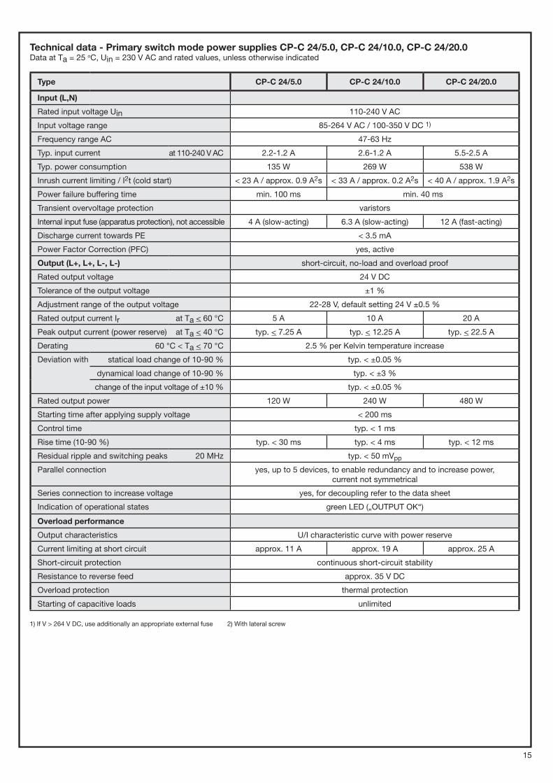
Technical data - Primary switch mode power supplies CP-C 24/5.0, CP-C 24/10.0, CP-C 24/20.0Data at Ta = 25 oC, Uin = 230 V AC and rated values, unless otherwise indicated
Type CP-C 24/5.0 CP-C 24/10.0 CP-C 24/20.0
Input (L,N)
Rated input voltage Uin 110-240 V AC
Input voltage range 85-264 V AC / 100-350 V DC 1)
Frequency range AC 47-63 Hz
Typ. input current at 110-240 V AC 2.2-1.2 A 2.6-1.2 A 5.5-2.5 A
Typ. power consumption 135 W 269 W 538 W
Inrush current limiting / I2t (cold start) < 23 A / approx. 0.9 A2s < 33 A / approx. 0.2 A2s < 40 A / approx. 1.9 A2s
Power failure buffering time min. 100 ms min. 40 ms
Transient overvoltage protection varistors
Internal input fuse (apparatus protection), not accessible 4 A (slow-acting) 6.3 A (slow-acting) 12 A (fast-acting)
Discharge current towards PE < 3.5 mA
Power Factor Correction (PFC) yes, active
Output (L+, L+, L-, L-) short-circuit, no-load and overload proof
Rated output voltage 24 V DC
Tolerance of the output voltage ±1 %
Adjustment range of the output voltage 22-28 V, default setting 24 V ±0.5 %
Rated output current Ir at Ta < 60 °C 5 A 10 A 20 A
Peak output current (power reserve) at Ta < 40 °C typ. < 7.25 A typ. < 12.25 A typ. < 22.5 A
Derating 60 °C < Ta < 70 °C 2.5 % per Kelvin temperature increase
Deviation with
statical load change of 10-90 % typ. < ±0.05 %
dynamical load change of 10-90 % typ. < ±3 %
change of the input voltage of ±10 % typ. < ±0.05 %
Rated output power 120 W 240 W 480 W
Starting time after applying supply voltage < 200 ms
Control time typ. < 1 ms
Rise time (10-90 %) typ. < 30 ms typ. < 4 ms typ. < 12 ms
Residual ripple and switching peaks 20 MHz typ. < 50 mVpp
Parallel connection yes, up to 5 devices, to enable redundancy and to increase power, current not symmetrical
Series connection to increase voltage yes, for decoupling refer to the data sheet
Indication of operational states green LED („OUTPUT OK“)
Overload performance
Output characteristics U/I characteristic curve with power reserve
Current limiting at short circuit approx. 11 A approx. 19 A approx. 25 A
Short-circuit protection continuous short-circuit stability
Resistance to reverse feed approx. 35 V DC
Overload protection thermal protection
Starting of capacitive loads unlimited
1) If V > 264 V DC, use additionally an appropriate external fuse 2) With lateral screw
15
Type CP-C 24/5.0 CP-C 24/10.0 CP-C 24/20.0
General data
Power dissipation typ. < 15 W typ. < 29 W typ. < 58 W
Efficiency typ. 89 %
MTBF 500.000 h
Mounting DIN rail (TH 35-15 or TH 35-7.5 acc. to IEC/EN 60715), snap-on mounting without any tool
Mounting position horizontal
Minimum distance to other units, horizontal/vertical 10 mm / 80 mm (0.39 in / 3.15 in)
Degree of protection housing / terminals IP20 / IP20
Material of enclosure housing shell / cover aluminium / zinc-coated sheet steel
Protection class ( EN 61140) I
Electrical connection - Input side pluggable connecting terminals, actuate only when power off
Wire size
fine-strand with wire end ferrule 0.2-2.5 mm 2 / 24-14 AWG 2.5-10 mm 2 / 14-8 AWG
fine-strand without wire end ferrule 0.2-2.5 mm 2 / 24-14 AWG 0.5-10 mm 2 / 20-8 AWG
rigid 0.2-2.5 mm 2 / 24-14 AWG 0.5-16 mm 2 / 20-6 AWG
Stripping length 7 mm / 0.27 inches 12 mm / 0.47 inches
Tightening torque 0.4 Nm / 3.54 lb.in
1.2-1.5 Nm / 10.62-13.27 lb.in
Electrical connection - Output side pluggable connecting terminals, actuate only when power off
Wire size
fine-strand with wire end ferrule 0.12-2.5 mm 2 / 26-14 AWG 2.5-10 mm 2 / 14-8 AWG
fine-strand without wire end ferrule 0.12-2.5 mm 2 / 26-14 AWG 0.5-10 mm 2 / 20-8 AWG
rigid 0.12-2.5 mm 2 / 26-14 AWG 0.5-16 mm 2 / 20-6 AWG
Stripping length 8 mm / 0.315 inches 12 mm / 0.47 inches
Tightening torque 0.4 Nm / 3.54 lb.in
1.2-1.5 Nm / 10.62-13.27 lb.in
Environmental data
Ambient temperature range
operation -25...+70 °C (-13...+158 °F)
full load 0...+60 °C (32...+140 °F), without derating
storage -40...+85 °C (-40...+185 °F)
Damp heat (IEC/EN 60068-2-3) 93 % at +40 °C (+104 °F), no condensation
Climatic class (IEC/EN 60721-3-3) 3K3
Isolation data
Rated impulse withstand voltage Uimp between all isolated circuits (IEC/EN 60950-1, EN 50178)
input / output 4 kV; 1.2/50 �s
input / PE 2.5 kV; 1.2/50 �s
output / PE 500 V; 1.2/50 �s
Pollution degree (IEC/EN 60950, EN 50178) 2
16