Embed Size (px)
Citation preview

CR800 series controller
Robot Safety Option Instruction Manual
4F-SF002-01
BFP-A3531-D
Mitsubishi Electric Industrial Robot


Safety Precautions
Always read the following precautions and the separate "Safety Manual" before starting use of the robot to learn the required measures to be taken.
CAUTION All teaching work must be carried out by an operator who has received special training. (This also applies to maintenance work with the power source turned ON.)
→Enforcement of safety training
CAUTION For teaching work, prepare a work plan related to the methods and procedures of operating the robot, and to the measures to be taken when an error occurs or when restarting. Carry out work following this plan. (This also applies to maintenance work with the power source turned ON.)
→Preparation of work plan
WARNING Prepare a device that allows operation to be stopped immediately during teaching work. (This also applies to maintenance work with the power source turned ON.)
→Setting of emergency stop switch
CAUTION During teaching work, place a sign indicating that teaching work is in progress on the start switch, etc. (This also applies to maintenance work with the power source turned ON.)
→Indication of teaching work in progress
DANGER Provide a fence or enclosure during operation to prevent contact of the operator and robot.
→Installation of safety fence
CAUTION Establish a set signaling method to the related operators for starting work, and follow this method.
→Signaling of operation start
CAUTION As a principle turn the power OFF during maintenance work. Place a sign indicating that maintenance work is in progress on the start switch, etc.
→Indication of maintenance work in progress
CAUTION Before starting work, inspect the robot, emergency stop switch and other related devices, etc., and confirm that there are no errors.
→Inspection before starting work

The points of the precautions given in the separate "Safety Manual" are given below. Refer to the actual "Safety Manual" for details.
DANGER When automatic operation of the robot is performed using multiple control devices (GOT, programmable controller, push-button switch), the interlocking of operation rights of the devices, etc. must be designed by the customer.
CAUTION Use the robot within the environment given in the specifications. Failure to do so could lead to faults or a drop of reliability. (Temperature, humidity, atmosphere, noise environment, etc.)
CAUTION Transport the robot with the designated transportation posture. Transporting the robot in a non-designated posture could lead to personal injuries or faults from dropping.
CAUTION Always use the robot installed on a secure table. Use in an instable posture could lead to positional deviation and vibration.
CAUTION Wire the cable as far away from noise sources as possible. If placed near a noise source, positional deviation or malfunction could occur.
CAUTION Do not apply excessive force on the connector or excessively bend the cable. Failure to observe this could lead to contact defects or wire breakage.
CAUTION Make sure that the workpiece weight, including the hand, does not exceed the rated load or tolerable torque. Exceeding these values could lead to alarms or faults.
WARNING Securely install the hand and tool, and securely grasp the workpiece. Failure to observe this could lead to personal injuries or damage if the object comes off or flies off during operation.
WARNING Securely ground the robot and controller. Failure to observe this could lead to malfunctioning by noise or to electric shock accidents.
CAUTION Indicate the operation state during robot operation. Failure to indicate the state could lead to operators approaching the robot or to incorrect operation.
WARNING When carrying out teaching work in the robot's movement range, always secure the priority right for the robot control. Failure to observe this could lead to personal injuries or damage if the robot is started with external commands.
CAUTION Keep the jog speed as low as possible, and always watch the robot. Failure to do so could lead to interference with the workpiece or peripheral devices.

CAUTION After editing the program, always confirm the operation with step operation before starting automatic operation. Failure to do so could lead to interference with peripheral devices because of programming mistakes, etc.
CAUTION Make sure that if the safety fence entrance door is opened during automatic operation, the door is locked or that the robot will automatically stop. Failure to do so could lead to personal injuries.
CAUTION Never carry out modifications based on personal judgments, non-designated maintenance parts. Failure to observe this could lead to faults or failures.
WARNING When the robot arm has to be moved by hand from an external area, do not place hands or fingers in the openings. Failure to observe this could lead to hands or fingers catching depending on the posture.
CAUTION Do not stop the robot or apply emergency stop by turning the robot controller's main power OFF. If the robot controller main power is turned OFF during automatic operation, the robot accuracy could be adversely affected. Also a dropped or coasted robot arm could collide with peripheral devices.
CAUTION Do not turn OFF the robot controller's main power while rewriting the robot controller's internal information, such as a program and parameter. Turning OFF the robot controller's main power during automatic operation or program/parameter writing could break the internal information of the robot controller.
DANGER Do not connect the Handy GOT when using the GOT direct connection function of this product. Failure to observe this may result in property damage or bodily injury because the Handy GOT can automatically operate the robot regardless of whether the operation rights are enabled or not.
DANGER Do not connect the Handy GOT to a programmable controller when using an iQ Platform compatible product with the CR800-R /CR800-Q controller. Failure to observe this may result in property damage or bodily injury because the Handy GOT can automatically operate the robot regardless of whether the operation rights are enabled or not.
DANGER Do not remove the SSCNET III cable while power is supplied to the multiple CPU system or the servo amplifier. Do not look directly at light emitted from the tip of SSCNET III connectors or SSCNET III cables of the Motion CPU or the servo amplifier. Eye discomfort may be felt if exposed to the light. (Reference: SSCNET III employs a Class 1 or equivalent light source as specified in JIS C 6802 and IEC60825-1 (domestic standards in Japan).)
DANGER Do not remove the SSCNET III cable while power is supplied to the controller. Do not look directly at light emitted from the tip of SSCNET III connectors or SSCNET III cables. Eye discomfort may be felt if exposed to the light. (Reference: SSCNET III employs a Class 1 or equivalent light source as specified in JIS C 6802 and IEC60825-1 (domestic standards in Japan).)

DANGER Attach the cap to the SSCNET III connector after disconnecting the SSCNET III cable. If the cap is not attached, dirt or dust may adhere to the connector pins, resulting in deterioration connector properties, and leading to malfunction.
CAUTION Make sure there are no mistakes in the wiring. Connecting differently to the way specified in the manual can result in errors, such as the emergency stop not being released. In order to prevent errors occurring, please be sure to check that all functions (such as the teaching box emergency stop, customer emergency stop, and door switch) are working properly after the wiring setup is completed.
CAUTION Use the network equipments (personal computer, USB hub, LAN hub, etc.) confirmed by manufacturer. The thing unsuitable for the FA environment (related with conformity, temperature or noise) exists in the equipments connected to USB. When using network equipment, measures against the noise, such as measures against EMI and the addition of the ferrite core, may be necessary. Please fully confirm the operation by customer. Guarantee and maintenance of the equipment on the market (usual office automation equipment) cannot be performed.
CAUTION To maintain the security (confidentiality, integrity, and availability) of the robot and the system against unauthorized access, DoS*1 attacks, computer viruses, and other cyberattacks from unreliable networks and devices via network, take appropriate measures such as firewalls, virtual private networks (VPNs), and antivirus solutions. Mitsubishi Electric shall have no responsibility or liability for any problems involving robot trouble and system trouble by unauthorized access, DoS attacks, computer viruses, and other cyberattacks. *1 DoS: A denial-of-service (DoS) attack disrupts services by overloading systems or exploiting vulnerabilities, resulting in a denial-of-service (DoS) state.

Revision history Date of print Manual No. Details of revisions
2017-05-31 BFP-A3531 First print 2018-06-01 BFP-A3531-A The CR800-Q controller was added.
Tables were corrected. (Stopping time and stopping distance (emergency stop), Stopping time and stopping distance (power off))
2019-10-31 BFP-A3531-B Added RV-8CRL. Added the length of the RIO cable. Amended "4.6.1 Test pulse diagnosis (EMG)".
2020-04-24 BFP-A3531-C Added information for the RH-3CRH and RH-6CRH. Added information on functions that cannot be used in
conjunction with the robot safety option. Amended "4.2.5 Recovery mode". Added the following error codes.
H2240, C2250, H2260, H2320 Added a solution to error H0241. Revised chapter 7 "SAFE STOPPING DISTANCE".
2021-04-01 BFP-A3531-D Updated some RT ToolBox3 screen images for Ver. 1.90U. Amended the precautions regarding the prevention of
unauthorized access. Corrected other mistakes and changed some sections. Added the following error codes.
C0244, H0250, H0251 Added EMC installation guideline. Revised "4.5.6 Safely-limited position function (SLP)". Added information to the safety performance and the
dangerous failure rate (Tab. 1–3).

Introduction
Thank you for purchasing an industrial robot from Mitsubishi Electric Corporation. The "robot safety option", used together with external devices such as a safety switch or light curtain, enhances the robot safety function. Before using the "robot safety option", make sure to read and fully understand the contents of this manual. The manual is intended for use on the assumption that you understand basic operations and functions of the Mitsubishi industrial robot. For the basic operation of the robot, refer to the separate "Instruction Manual/Detailed explanations of functions and operations".
Symbols in this manual
Danger Incorrect handling may result in imminent danger, leading to death or serious
injury.
Warning Incorrect handling may lead to death or serious injury.
Caution Incorrect handling may result in property damage, or danger leading to
impairment of the user.
・ No part of this manual may be reproduced by any means or in any form, without prior consent from Mitsubishi.
・ The details of this manual are subject to change without notice. We kindly ask for your understanding.
・ Specification values are based on our standard test methods. ・ An effort has been made to make full descriptions in this manual. However, if any discrepancies or
unclear points are found, please contact your service provider. ・ This is the original document. ・ All other company names and production names in this document are the trademarks or registered
trademarks of their respective owners. ・ We omit ® and TM in this document.
Copyright(C) 2017-2021 MITSUBISHI ELECTRIC CORPORATION ALL RIGHTS RESERVED

[CONTENTS] 1. FUNCTIONS AND CONFIGURATION .............................................................................................. 1-1
1.1 Overview ................................................................................................................................................... 1-1 1.2 System Configuration .............................................................................................................................. 1-2 1.3 Specifications ........................................................................................................................................... 1-3 1.4 Risk Assessment ..................................................................................................................................... 1-4
1.4.1 Residual Risk (Common) ................................................................................................................... 1-4 1.4.2 Residual Risk (Specific to Each Function) ...................................................................................... 1-4
2. INSTALLATION .................................................................................................................................. 2-6 2.1 Product Components............................................................................................................................... 2-6
2.1.1 Accessories......................................................................................................................................... 2-6 2.1.2 Customer-prepared items .................................................................................................................. 2-7
2.2 Names of Each Part ................................................................................................................................. 2-8 2.3 Installation and Connection .................................................................................................................... 2-9
2.3.1 Fixing the safety extension unit ........................................................................................................ 2-9 2.3.2 Safety extension unit external dimensions ..................................................................................... 2-9 2.3.3 Connecting with the robot controller ............................................................................................. 2-10 2.3.4 Connector and cable ......................................................................................................................... 2-11
2.4 Check Items ............................................................................................................................................ 2-12 2.5 Replacement Parts ................................................................................................................................. 2-12 2.6 Maintenance ........................................................................................................................................... 2-12
3. SIGNALS AND WIRING .................................................................................................................. 3-13 3.1 Description of Signals ........................................................................................................................... 3-13
3.1.1 Electrical specifications .................................................................................................................. 3-13 3.1.2 Signal operation ............................................................................................................................... 3-15
3.2 Connectors and Pin Assignment.......................................................................................................... 3-16 3.3 Input Signal Connection Example ........................................................................................................ 3-18 3.4 Measures to Prevent Static Electricity and Noise .............................................................................. 3-21
4. SAFETY MONITORING FUNCTIONS ............................................................................................. 4-22 4.1 Safety Monitoring Functions Overview ............................................................................................... 4-22
4.1.1 Simulation ......................................................................................................................................... 4-22 4.2 Startup and Basic Configuration .......................................................................................................... 4-23
4.2.1 Connecting RT ToolBox3 ................................................................................................................. 4-23 4.2.2 Parameter configuration .................................................................................................................. 4-23 4.2.3 Password setting .............................................................................................................................. 4-24 4.2.4 Enabling/disabling functions .......................................................................................................... 4-26 4.2.5 Recovery mode ................................................................................................................................. 4-27 4.2.6 Parameter CRC output number ....................................................................................................... 4-28
4.3 Defining 3D Models ................................................................................................................................ 4-30 4.3.1 3D Monitor ......................................................................................................................................... 4-30 4.3.2 Arm model ......................................................................................................................................... 4-33 4.3.3 Tool model ......................................................................................................................................... 4-34
4.4 Safety Logic Edit .................................................................................................................................... 4-35 4.4.1 Safety input settings ........................................................................................................................ 4-35 4.4.2 Safety output configuration ............................................................................................................ 4-44 4.4.3 Checking operation of the safety inputs and outputs .................................................................. 4-46
4.5 Safety Monitoring Functions ................................................................................................................ 4-47 4.5.1 Safe torque off (STO) ....................................................................................................................... 4-47 4.5.2 Safe operating stop (SOS) ............................................................................................................... 4-48 4.5.3 Safe stop 1 (SS1) .............................................................................................................................. 4-51 4.5.4 Safe stop 2 (SS2) .............................................................................................................................. 4-54 4.5.5 Safely-limited speed function (SLS) ............................................................................................... 4-57 4.5.6 Safely-limited position function (SLP) ........................................................................................... 4-65

4.6 Safety Diagnosis Function .................................................................................................................... 4-74 4.6.1 Test pulse diagnosis (EMG)............................................................................................................. 4-74
5. STATE VARIABLE ........................................................................................................................... 5-75 5.1 List of State Variables ............................................................................................................................ 5-75 5.2 State Variables ........................................................................................................................................ 5-75
6. TROUBLESHOOTING ..................................................................................................................... 6-80 6.1 Error List for the Safety Monitoring Functions ................................................................................... 6-80 6.2 Errors Whose Specification Is Changed by Safety Monitoring Functions ...................................... 6-83
7. SAFE STOPPING DISTANCE ......................................................................................................... 7-84 7.1 How to Calculate a Stopping Distance ................................................................................................ 7-84 7.2 Maximum Stopping Time and Maximum Operating Angle ................................................................ 7-85 7.3 Calculating stopping distance and stopping time ............................................................................ 7-108
8. APPENDIX ..................................................................................................................................... 8-111 8.1 Appendix 1: EMC installation guideline .............................................................................................. 8-111
8.1.1 Outlines ............................................................................................................................................ 8-111 8.1.2 EMC directive ................................................................................................................................... 8-111 8.1.3 EMC measures ................................................................................................................................. 8-111 8.1.4 Component parts for EMC measures ............................................................................................8-112

1 FUNCTIONS AND CONFIGURATION
Overview 1-1
1. FUNCTIONS AND CONFIGURATION
1.1 Overview This document explains how to use the safety monitoring functions with the robot safety option. As for the functions available in the standard robot controller and the operation method, refer to the instruction manual provided with the robot controller. The robot safety option adds the safety monitoring functions to CR800 series controllers. The main functions are as follows:
Tab. 1-1: Safety monitoring functions overview
Function Function Outline See: Safety logic edit Input This allows defining conditions to trigger the safety
monitoring functions. Safety input signals from external sensors (laser scanners, light curtains, etc.) and robot area information can be combined to configure the conditions to trigger the safety monitoring functions.
4.4 Safety Logic Edit
Output This allows outputting safety signals based on the safety monitoring functions and area information. This is used for displaying safety states or connecting other safety devices.
Safe stop function 1 SS1 (STO)
This is a function to stop the robot safely. After stopping the robot, power off the motors.
4.5.3 Safe stop 1 (SS1)
Safe stop function 2 SS2 (SOS)
This is a function to stop the robot safely. While the motor control keeps working after the robot stops, this function monitors the robot so that it does not continue to operate.
4.5.4 Safe stop 2 (SS2)
Safely-limited speed function
SLS This is a function to monitor the robot arm and robot tools so that their speed does not exceed a specified limit. This can monitor the speeds both in XYZ coordinates and joint coordinates.
4.5.5 Safely-limited speed function (SLS)
Safely-limited position function
SLP This is a function to monitor the position of the robot arm and robot tools so that they do not enter safeguarded spaces. Safeguarded spaces can be specified with planes and areas.
4.5.6 Safely-limited position function (SLP)

1 FUNCTIONS AND CONFIGURATION
1-2 System Configuration
1.2 System Configuration
エリアセンサ
ランプ
ライトカーテン
非常停止
安全シーケンサ
安全拡張ユニット
Fig. 1-1 System configuration
Tab. 1-2 System configuration
Item Description Remarks Robot arm Vertically
articulated type RV-FR series
RV-2FRB, RV-2FRLB, RV-4FR, RV-4FRL, RV-4FRJL, RV-7FR, RV-7FRL, RV-7FRLL, RV-13FR, RV-13FRL, RV-20FR
Additional axes and user mechanisms are not included in the system.
Vertically articulated type RV-CR series
RV-8CRL
SCARA type RH-FR series
RH-3FRH, RH-6FRH, RH-12FRH, RH-20FRH, RH-3FRHR, RH-1FRHR
SCARA type RH-CR series
RH-3CRH, RH-6CRH
Robot controller CR800-D Ver. A1 or later Ver. A5c or later for the RV-8CRL, and Ver. A5k or later for the RH-3CRH and RH-6CRH.
CR800-R Ver. A1 or later CR800-Q Ver. A2 or later
RT ToolBox3 3F-15C-WINE Install the software to a personal computer. The software is used to enable the safety monitoring function. (Separate purchase is required.) Ver. 1.61P or later for the RV-8CRL, and Ver. 1.70Y or later for the RH-3CRH and RH-6CRH.
RT ToolBox3 mini 3F-14C-WINE RT ToolBox3 Pro 3F-16D-WINE
Robot safety option 4F-SF002-01 The option explained in this instruction manual.
External device Light curtain, safety switch, etc. To be prepared by the customer according to the system configuration.
Emergency stop
Safety extension unit
Lamp
Light curtain
Laser scanner Safety sequencer

1 FUNCTIONS AND CONFIGURATION
Specifications 1-3
1.3 Specifications Tab. 1-3 Specifications
Item Description Remarks Safety
function STO function The function electrically shuts off
the driving energy to the motor of the robot arm.
IEC 60204-1 Corresponds to stop category 0
SS1 function The function to control and decelerate the motor speeds of the robot. After stopping, the robot transitions to the STO state.
IEC 60204-1 Corresponds to stop category 1
SS2 function The function to control and decelerate the motor speeds of the robot. After stopping, the robot transitions to the SOS state.
IEC 60204-1 Corresponds to stop category 2
SOS function Without shutting off the driving energy to the motors, this function monitors the robot so that it stays at rest.
EN61800-5-2 compliant
SLS function This is a function to monitor each part of the robot arm so that their speeds do not exceed monitoring speeds.
EN61800-5-2 compliant
SLP function The function monitors specified monitoring positions so that they do not go across position monitoring planes.
EN61800-5-2 compliant
Safety performance
Standard ISO10218-1(2011) EN62061(2006) ISO13849-1(2015) IEC61508 (2010) EN61800-5-1 (ES, EN for Drive) EN61800-5-2(Safety function Drive) IEC61326-3-1 (EMC for RS) EN60204-1
Safety level STO SIL 3, PLe/Category 4 External emergency stop input (when the test pulse diagnosis is set) (Note 1)
SIL 2, PLd/Category 3 Safety extension unit, external emergency stop input (at factory settings)
SS1, SOS, SS2, SLS, SLP
SIL 2, PLd/Category 3 Safety extension unit
Dangerous failure rate
STO PFH = 1.40×10⁻⁸ [1/h] External emergency stop input (when the test pulse diagnosis is set) (Note 1)
SS1, SOS, SS2, SLS, SLP
PFH = 3.42×10⁻⁷ [1/h] Safety extension unit
Safety extension
unit
Power supply specifications
Voltage 24 V DC±5% Ripple 0.2 V (P-P)
Maximum consumption current
300 mA
Structure (IP rating) IP20 Weight 0.8kg Environment Operating
temperature range
0 to 40 It must be kept away from heat appliances and other heat sources.

1 FUNCTIONS AND CONFIGURATION
1-4 Risk Assessment
Item Description Remarks Relative humidity
45 to 75 Non-condensing
Vibration During transportation: 34m/s2. During operation: 5 m/s2 or less
Atmosphere No corrosive gas / flammable gas / oil mist/dust
Installation environment
Indoors Place where no intense electromagnetic energy is generated No roughness or tilt on the installation surface
No direct sunlight. Do not install the unit on very rough surfaces.
Input signal Eight routes (duplex signal) Output signal Four routes (duplex signal)
Note 1: For details on setting the pulse test for the input, refer to the following section: See 4.6.1 Test pulse diagnosis (EMG).
1.4 Risk Assessment To ensure safety, the user needs to assess all the risks and determine residual risks for the mechanical system as a whole. Companies or individuals who configure the system will accept full responsibility for installation and authorization of the safety system. Assessment for all risks and safety level certification are required for the equipment/system as a whole. The following shows residual risks related to the safety monitoring function of this product.
1.4.1 Residual Risk (Common) (1) If the origin setting, parameter settings or programs of the robot are incorrect, unexpected operation may
occur and safety cannot be ensured. Fully check whether operations are as intended. (2) Until correct installation, wiring, and adjustment are achieved, safety cannot be ensured. (3) Only a qualified person is given the authority to install, start, repair, adjust, etc. the equipment to which
devices are installed. Installing or operating the equipment should be done by a trained engineer. (4) For the safety monitoring function, perform the wiring separately from other signal wirings. (5) Protect cables by appropriate means (installing inside the control panel, using a cable guard, etc.). (6) It is recommended to use switches, relays, sensors, etc. conforming to safety standards. For using switches,
relays, sensors, etc. not conforming to safety standards, sufficient verification of safety is necessary on the customer side.
(7) The safety function only works for the robot controller and the robot. The function covers no additional axes (additional robot axes, user mechanisms). When using an additional axis, the customer needs to ensure and assess the safety of the axis.
(8) To perform the initial test of the robot, power cycle it regularly. The initial test should be performed at least every six months.
1.4.2 Residual Risk (Specific to Each Function) (1) STO function This function interrupts transmission of power to the motor installed in the robot arm, and may bring variation to the posture of the robot arms due to mechanical factors, such as a timing belt break or brake wear, etc. of the robot arm. Periodic maintenance of the robot arm is required. Depending on the posture of the robot, the arm may droop if the axis does not have a brake. (2) SS1function This function controls and decelerates the motor speed installed to a robot arm. The movement cannot be stopped immediately after deceleration is started. (3) SS2 function

1 FUNCTIONS AND CONFIGURATION
Risk Assessment 1-5
This function controls and decelerates the motor speed installed to a robot arm. The movement cannot be stopped immediately after deceleration is started. (4) SOS function This function monitors motors installed in the robot so that they stay at rest. Mechanical factors, such as break of timing belts of the robot, may bring variation to the posture of the robot. Periodic maintenance of the robot arm is required. (5) SLS function This function monitors the speed of each part of the robot arm and tools specified beforehand. Depending on the robot posture, some undefined parts may move at a speed higher than the monitoring speed. This function is only enabled when the robot is in the servo-on state and therefore does not monitor the speed when the robot is in the servo-off state. (6) SLP function In the following cases, the monitoring position may go across a position monitoring plane or a position monitoring area. The following shows some concrete examples.
• When the position monitoring plane is applied, the robot position is beyond the plane. • When the position monitoring plane is applied, the robot is moving near the plane at a high speed. • The robot posture changes when the robot brake is released.
(7) Duplex input and output signal monitoring function This function only monitors whether the duplexed input signals match each other, and does not detect malfunction or misconnection of the connected devices. The robot detects the mismatched signal when a signal mismatch for 0.1 seconds or more occurs.

2 INSTALLATION
2-6 Product Components
2. INSTALLATION
2.1 Product Components 2.1.1 Accessories Please check to see if the package has all the necessary parts before use.
Tab. 2-1 List of items included in the package
Number Item Quantity Outer appearance Model 1 Safety extension unit 1
4F-SFUNIT
2 RIO cable (Cable length: 1 m)
1
2F-SFRIOCBL
3 DCIN connector set 1
1 pcs.
3 pcs.
2F-SFDCINCON
4 SDI connector set 1
8 pcs.
32 pcs.
2F-SFSDICON
5 SDO connector set 1
2 pcs.
16 pcs.
2F-SFSDOCON
6 Termination resistor 1
2F-SFTM
7 Instruction manual 1
CD-ROM
BFP-A3543

2 INSTALLATION
Product Components 2-7
2.1.2 Customer-prepared items Tab. 2-2 Customer-prepared items
No. Item Quantity Description Remarks 1 24 V power supply 1 The power supply for the safety
extension unit.
2 24 V power cable - This is used to supply the safety extension unit with the 24 V power. Assemble the cable with the included DCIN connector set.
3 Cable for SDI1 and SDI2 connectors
- This is used to input the safety input signals to the safety extension unit. Assemble the cable with the included SDI connector set.
4 Cable for SDO1 and SDO2 connectors
- This is used to output the safety output signals from the safety extension unit. Assemble the cable with the included SDO connector set.

2 INSTALLATION
2-8 Names of Each Part
2.2 Names of Each Part The names of each part of the safety extension unit (4F-SFUNIT) are shown below:
Fig. 2-1 Names of each part of the safety unit
Tab. 2-3 Names of each part of the safety extension unit
No. Connector Function Remarks (1) CJ31 Unavailable (2) CJ32 Unavailable (3) SDI1 Safety DI input connectors Eight points for duplication.
0 V common. (4) SDI2 Safety DI input connectors
(5) RIO1 Remote I/O communication ver. 2.0 connector
(6) RIO2 Remote I/O communication ver. 2.0 connector
(7) DCIN/DCOUT 24 V I/O connector The power input to the safety I/O unit.
DCOUT is unavailable. (8) FG FG terminal Use this terminal for grounding. (9) SDO1 Safety relay output connector Four points for duplication
Non-voltage contact output (10) SDO2 Safety relay output connector
(11) STATION NO. Station number setting switch This is set to station number 2 before shipping. Do not change the setting.
(12) ALM LED Remote I/O communication error check LED
On: Error Off: Normal
(13) DCIN LED 24 V DC power check LED On: Normal Off: Error
(14) FUSE LED Melted fuse check LED On: Normal Off: Fuse melted
(15) H1 LED ,H2 LED H3 LED, H4 LED Welded relay check LED On: Normal
Off: Relay welded

2 INSTALLATION
Installation and Connection 2-9
2.3 Installation and Connection Make sure the power of the robot controller is turned OFF before fixing the safety extension unit, connecting the robot controller and the safety extension unit, or installing the connectors to the safety extension unit. Please pay attention to the orientation of insertion of the connectors. The connectors may be broken if they are forcibly inserted in an incorrect orientation.
When an operator with static electricity installs/connects the product, the robot controller or the safety extension unit may be broken. Start the work after all static electricity is discharged.
Please supply power to the safety extension unit before the robot controller. When the controller is turned on before the unit, H311(RemoteI/O unit config error) may occur. When this error occurs, turn off both of the unit and controller and supply power to the
unit before the controller.
2.3.1 Fixing the safety extension unit To fix the safety extension unit, use the hole marked with *1 in the external view Fig. 2-2 External dimensions. Alternatively, use DIN rails and fix it in a place free from vibration.
2.3.2 Safety extension unit external dimensions
Fig. 2-2 External dimensions
M5ネジ用穴(3ケ所)(*1)M5 screw hole (×3) (*1)
Caution
Caution
Caution
Caution

2 INSTALLATION
2-10 Installation and Connection
2.3.3 Connecting with the robot controller (1) Unit connection By using the RIO cable (2F-SFRIOCBL) included in this product, connect the robot controller to the safety extension unit.
Fig. 2-3 Connection to the CR800 controller
(2) Station number • Set the station number switch to station number 2. A wrong switch setting will cause error H2261.
Fig. 2-4 Station number setting switch
Termination resistor (2F-SFTM)
RIO cable (2F-SFRIOCBL)
Safety extension unit (4F-SFUNIT)
CR800 controller
Station number setting switch
Station number setting 1 Station number setting 2

2 INSTALLATION
Installation and Connection 2-11
2.3.4 Connector and cable
Incorrect cable connection to a wiring connector may damage the robot or cause a malfunction. Take sufficient care when connecting the cables to a wiring connector.
To assemble the cables to connect to the DCIN, SDI1, SDI2, SDO1, and SDO2 connectors, use the included connector set.
Tab. 2-4 Connector and cable
No. Connector Accessories needed
Description Recommended cable
1 DCIN/DCOUT 2F-SFDCINCON
Manufacturer Model Qty. TE Connectivity 2-178288-3 1 TE Connectivity 1-175218-5 3
Conductor area: 0.5 to 1.42 mm2, (20 to 16 AWG) Sheath diameter: 1.8 to 2.8 mm With shields
2 SDI1 SDI2
2F-SFSDICON
Manufacturer Model Qty. TE Connectivity 175363-1 8 TE Connectivity 175218-2 32
Conductor area: 0.5 to 1.42 mm2, (20 to 16 AWG) Sheath diameter: 1.8 to 2.8 mm With shields
3 SDO1 SDO2
2F-SFSDOCON
Manufacturer Model Qty. TE Connectivity 178289-4 2 TE Connectivity 175218-2 16
Conductor area: 0.5 to 1.42 mm2, (20 to 16 AWG) Sheath diameter: 1.8 to 2.8 mm With shields
Caution

2 INSTALLATION
2-12 Check Items
2.4 Check Items Check the following items periodically.
(1) Make sure the connector is securely inserted to the safety extension unit. (2) Make sure the electric wire has not come off from the wiring connector. (3) Make sure no screws affixed to the safety extension unit are loose. (4) Make sure the connectors connecting the robot controller and the safety extension unit are securely
inserted.
2.5 Replacement Parts No part requires regular replacement.
2.6 Maintenance In the following cases, contact your service provider. Relay failure
Maintenance due to a relay failure requires the replacement of the unit. (Note). (Note) The relays are fixed onto the board, which makes it impossible to only replace a relay.
Melted fuse When a melted fuse has turned off the melted fuse check LED, the unit needs replacing.

3 SIGNALS AND WIRING
Description of Signals 3-13
3. SIGNALS AND WIRING
3.1 Description of Signals 3.1.1 Electrical specifications (1) Safety DI input specifications
Tab. 3-1 Safety DI electrical specifications
Item Specifications Remarks Input type 0 V common - Input point Eight points 16 points for duplication Input voltage at external contact ON 18 V or more - Minimum current at external contact ON 3 mA or more - Input voltage at external contact OFF 3.8 V max. - Input current at external contact OFF 1 mA max. - Input resistor 5 kΩ - Allowable chattering time 1 ms max. - Input signal holding time 40 ms or more 40 ms is just a standard. The input signal is
not recognized unless the time is held more than the entered DSI filter time.
Input circuit operation delay time 1 ms to 2 ms - Machine side contact capacity 30 V or more,
16 mA or more -
Insulated/uninsulated Uninsulated -
Fig. 3-1 Safety DI electrical specifications
Customer-prepared item Safety extension unit
Control circuit
Control circuit

3 SIGNALS AND WIRING
3-14 Description of Signals
(2) Safety DO output specifications
Tab. 3-2 Safety DO electrical specifications
Item Specifications Remarks Output type Non-voltage contact
output Relay contact
Output point 4 points 8 points for duplication Maximum allowable contact voltage 250 V AC, 125 V DC - Maximum allowable contact current 6 A - Response time 8 ms max. - Restoration time 20 ms max. - Insulated/uninsulated Insulated Insulated by the relay
Fig. 3-2 Safety DO electrical specifications
Control circuit
Control circuit
Safety extension unit
Customer device
Customer device

3 SIGNALS AND WIRING
Description of Signals 3-15
3.1.2 Signal operation (1) DSI signal
The DSI signals are used to switch items that the safety monitoring function monitors. Each of the signals is duplex and the states of the two input signals need to be identical to each other. If the states of the two input signals are different, an error occurs. A 100-ms continuous discrepancy between DSI_A and DSI_B causes error H222* (DSI mismatch) and the SS1 function stops the robot.
Tab. 3-3: DSI Input states
Signal input state Remarks DSI_A DSI_B
DSI Input states
Enabled OFF OFF - ON OFF A 100-ms continuous discrepancy between
DSI_A and DSI_B will cause an error and start SS1.
OFF ON
Disabled ON ON - The DSI signal screen of RT ToolBox3 enables monitoring the input states of the DSI-A and DSI-B signals on it. Input the DSI signal individually from the peripheral devices and test to see if ON/OFF state of the signal or wiring is correct. The DSI signal screen can be displayed by selecting [Online]→[Monitor]→[Signal]→[DSI signal] in Workspace.
Fig. 3-3 DSI signal monitor
(2) DSO signal
The DSO signals are for outputting the state of the safety monitoring function. DSO1 to DSO4 can be assigned with output safety function and AREA signals. The outputs are duplex and a 100-ms continuous discrepancy between DSO_A and DSO_B signals causes error H.2230 (DSO mismatch) to be output and the SS1 function stops the robot.
Tab. 3-4: DSO output states
Signal output state Remarks DSO_A DSO_B
DSO output states
Enabled ON ON - Disabled OFF OFF -
(3) Exclusive input/output signals
DSI signal and DSO signal are assigned to exclusive input/output signals 128 ~ 191. When the safety function is enabled and any exclusive input/output signals are assigned to 128 ~ 191, L.6641(Duplicate setting (special IN)) and L.6650 (Duplicate setting (special OUT)) occur.

3 SIGNALS AND WIRING
3-16 Connectors and Pin Assignment
3.2 Connectors and Pin Assignment
Tab. 3-5 DCIN/DCOUT pin assignment
Terminal name
Signal name Signal description Remarks
A1 - - Unused (Note 1)
B1 DC24V +24 V power supply (input)
A2 - - Unused (Note 1) B2 GND 0V A3 - - Unused (Note 1) B3 FG Frame ground
Note 1: You can also use A1 as DC24V, A2 as GND, A3 as FG. In that case, do not connect the connector to B1, B2, B3.
Tab. 3-6 SDI1 and SDI2 pin assignment
SDI1 SDI2
Terminal name Signal name Signal description Terminal name Signal name Signal
description
A1 DSI1A Safety input 1A A1 DSI6A Safety input 6A
B1 COM+ +24 V output B1 COM+ +24 V output
A2 DSI1B Safety input 1B A2 DIS6B Safety input 6B
B2 COM+ +24 V output B2 COM+ +24 V output
A3 DSI2A Safety input 2A A3 DSI7A Safety input 7A
B3 COM+ +24 V output B3 COM+ +24 V output
A4 DSI2B Safety input 2B A4 DSI7B Safety input 7B
B4 COM+ +24 V output B4 COM+ +24 V output
A5 DSI3A Safety input 3A A5 DSI8A Safety input 8A
B5 COM+ +24 V output B5 COM+ +24 V output
A6 DSI3B Safety input 3B A6 DSI8B Safety input 8B
B6 COM+ +24 V output B6 COM+ +24 V output A7 DSI4A Safety input 4A B7 COM+ +24 V output A8 DSI4B Safety input 4B B8 COM+ +24 V output A9 DSI5A Safety input 5A B9 COM+ +24 V output A10 DSI5B Safety input 5B B10 COM+ +24 V output
Connector on the unit
Fig. 3-4 DCIN/DCOUT connector

3 SIGNALS AND WIRING
Connectors and Pin Assignment 3-17
Fig. 3-5 SDI connector
Tab. 3-7 SDO1 and SDO2 pin assignment
SDO1 SDO2
Terminal name Signal name Signal description Terminal name
Signal name Signal description
A1 DSO1A Safety relay output 1A A1 DSO1B Safety relay output 1B B1 DSO1A Safety relay output 1A B1 DSO1B Safety relay output 1B A2 DSO2A Safety relay output 2A A2 DSO2B Safety relay output 2B B2 DSO2A Safety relay output 2A B2 DSO2B Safety relay output 2B A3 DSO3A Safety relay output 3A A3 DSO3B Safety relay output 3B B3 DSO3A Safety relay output 3A B3 DSO3B Safety relay output 3B A4 DSO4A Safety relay output 4A A4 DSO4B Safety relay output 4B B4 DSO4A Safety relay output 4A B4 DSO4B Safety relay output 4B
Fig. 3-6 SDO connector
SDI2 connector SDI1 connector
Connector on the unit Connector on the unit
SDO2 connector SDO1 connector
Connector on the unit Connector on the unit

3 SIGNALS AND WIRING
3-18 Input Signal Connection Example
3.3 Input Signal Connection Example Fig. 3-7 shows a signal connection example. Devices to be connected depend on the user's system configuration.
Fig. 3-7 Input signal connection example
DSI1A
DSI2A
DSI1B
DSI2B
DSI3B
DSI3A
DSI4B
DSI4A
DSI5B
DSI5A
Connector pin numbers Safety extension unit
Control circuit
Control circuit
Photocoupler
Photocoupler
Photocoupler
Photocoupler
Photocoupler
Photocoupler
Photocoupler
Photocoupler
Photocoupler
Photocoupler
+
+
+
+
+

3 SIGNALS AND WIRING
Input Signal Connection Example 3-19
Fig. 3-8 Input signal connection example
DSI6B
DSI6A
DSI7B
DSI7A
DSI8B
DSI8A
Photocoupler
Photocoupler
Photocoupler
Photocoupler
Photocoupler
Photocoupler
Control circuit
Control circuit
Safety extension unit Connector pin numbers
+
+
+

3 SIGNALS AND WIRING
3-20 Input Signal Connection Example
<Safety DO connection example>
Fig. 3-9 Output signal connection example
DSO1A
DSO1A
DSO1B
DSO1B
DSO2A
DSO2A
DSO2B
DSO2B
Connector pin numbers
Connector pin numbers
Safety extension unit
Safety extension unit
Control circuit
Control circuit
Control circuit
Control circuit
Load
Load
Load
Load

3 SIGNALS AND WIRING
Measures to Prevent Static Electricity and Noise 3-21
Fig. 3-10 Output signal connection example
3.4 Measures to Prevent Static Electricity and Noise Use a shielded wire to avoid effects of noise. Perform wiring through the shortest path so that the cable length can become shorter. In case of malfunction, etc. due to noise or static electricity, ground the unit using the grounding terminals. Static electricity may cause a malfunction. Do not touch the unit when you are statically charged. Take measures such as installing the safety extension unit in an enclosure.
DSO3A
DSO3A
DSO3B
DSO3B
DSO4A
DSO4A
DSO4B
DSO4B
Safety extension unit
Safety extension unit
Control circuit
Control circuit
Control circuit
Control circuit
Connector pin numbers
Connector pin numbers
Load
Load
Load
Load

4 SAFETY MONITORING FUNCTIONS
4-22 Safety Monitoring Functions Overview
4. SAFETY MONITORING FUNCTIONS
4.1 Safety Monitoring Functions Overview The functions available on the robot safety option are shown below:
Tab. 4-1 Safety Monitoring Functions Overview
Function Functional description See: Safety logic edit Input This allows defining conditions for the safety monitoring
function to work. Safety input signals and the AREA information of the robot can be combined to configure the conditions to trigger the safety monitoring functions.
4.4 Safety Logic Edit
Output This allows outputting safety signals based on running states of the safety monitoring functions and AREA monitoring information. This is used for displaying safety states or connecting other safety devices.
Safe torque off STO The function shuts off driving energy to the motors of the robot.
4.5.1 Safe torque off (STO)
Safe operating stop SOS Without shutting off the driving energy to the motors, this function monitors the robot so that it stays at rest.
4.5.2 Safe operating stop (SOS)
Safe stop function 1 SS1 This is a function to stop the robot safely. After stopping the robot, power off the motors.
4.5.3 Safe stop 1 (SS1)
Safe stop function 2 SS2 This is a function to stop the robot safely. While the motor control keeps working after the robot stops, this function monitors the robot so that it does not work.
4.5.4 Safe stop 2 (SS2)
Safely-limited speed function
SLS
This is a function to monitor the robot arm and the tools so that their speeds do not exceed specified limits. • Speed monitoring in XYZ coordinates • Speed monitoring in joint coordinates
4.5.5 Safely-limited speed function (SLS)
Safely-limited position function
SLP
This is a function to monitor whether positions of the robot arm and the hand are in a safe area.
4.5.6 Safely-limited position function (SLP)
4.1.1 Simulation You can check operation of safety monitoring function with simulation on RT ToolBox3/RT ToolBox3 Pro. (This simulation is not available on RT toolBox3 mini. ) Safety input (DSI) is assigned as following table. Switch DSI using Pseudo-input.
DSI 1 2 3 4 5 6 7 8 Signal No. 128 129 130 131 132 133 134 135
See “RT ToolBox3/RT ToolBox3 mini User’s Manual” for details on using simulation and pseudo-input. Restrictions
The following functions and options cannot be used in conjunction with the robot safety option. • Parallel I/O interface (2A-RZ361, 2A-RZ371) • Controller CPU drive mode function • Machine lock function • Pseudo-input function
* The pseudo-input function can be used in RT ToolBox3 simulations. • CPU standalone mode function

4 SAFETY MONITORING FUNCTIONS
Startup and Basic Configuration 4-23
4.2 Startup and Basic Configuration The safety monitoring function is disabled in the factory default setting. To use the safety monitoring function, it needs enabling and parameters for each monitoring function needs configuring. Changing the parameters for the safety monitoring functions requires RT ToolBox3, RT ToolBox3 mini, or RT ToolBox3 Pro separately.
4.2.1 Connecting RT ToolBox3 The safety monitoring function is configured in the online state by connecting RT ToolBox3 to the controller. For information on how to connect RT ToolBox3 to the controller, refer to "RT ToolBox3 / RT ToolBox3 mini Instruction manual" coming with RT ToolBox3.
4.2.2 Parameter configuration Monitoring start conditions for the safety monitoring functions and the monitoring functions are configured through the editing screen for safety monitoring function parameters of RT ToolBox3. (1) Editing screen for the safety monitoring function parameters
To open the editing screen for the safety monitoring function parameters, from Workspace, select [Online] -> [Parameter] -> [Safety Parameter] -> [Safety option] and then select an applicable screen, which enables configuring and changing parameters concerning the safety monitoring function.
Fig. 4-1 Editing screen for the safety monitoring function parameters
Parameters displayed on the editing screen for the safety monitoring function parameters can only be viewed or changed through this screen. The settings cannot be viewed or changed on the parameter list screen of RT ToolBox3 or the parameter editing screen of the teaching pendant (TB in short).
Caution
Displays editing screens for the safety monitoring function parameters.

4 SAFETY MONITORING FUNCTIONS
4-24 Startup and Basic Configuration
(2) Parameter setting procedure Set the parameters in the following steps.
Connect RT ToolBox3 to the controller and put it in the online state.
Display the editing screen for the safety monitoring function parameters, and set each parameter. Enter the password when you write the settings to the controller.
Read each parameter and confirm that it is set correctly.
The parameter settings take effect after the controller is power-cycled.
4.2.3 Password setting The password must be changed from the default setting in order to use the safety monitoring function.
The password is configured to prevent the safety monitoring function parameters from being changed inadvertently. The first thing to do when using the safety monitoring functions is to change the factory default password to new one. (Viewing the parameter settings does not require the password.) (1) Factory default password
The factory default password is "MELFASafetyPSWD". Unless the password is changed, error L7378 (Change password) occurs when a parameter change is attempted for a parameter related to the safety monitoring function, and the parameter cannot be changed.
(2) Password change
To change the password, open the Basic Configuration screen for the safety monitoring functions. From Workspace, select [Online] -> [Parameter] -> [Safety Parameter] -> [Safety option] -> [Basic Configuration]. (Robots incompatible with the safety monitoring function do not have [Safety parameter] in the [Movement Parameter] tree.)
Fig. 4-2: Basic Configuration screen
Caution
Connecting RT ToolBox3
Parameter configuration
Parameter verification
Turn ON the power supply again

4 SAFETY MONITORING FUNCTIONS
Startup and Basic Configuration 4-25
Press the [Change Password] button on the bottom of the editing screen for parameters related to the safety monitoring function to display [Register/Change Password]. Change the password by entering a new and the current passwords.
Fig. 4-3 Register/Change Password screen
Use 8 to 32 single-byte characters for the password. Available characters are alphanumeric characters (0 to 9, A to Z, and a to z), and they are case-sensitive.
If you forget the password, parameters related to the safety monitoring function cannot be changed. Take care to not forget the registered password. If you forget the password, you need to restore the factory settings by clearing the memory of the controller with the device reset operation. For the device reset operation, refer to "Instruction manual/Detailed explanations of functions and operations" provided with the robot.
To prevent unintended change of parameters, keep passwords in a secure place so that it does not leak to any third parties.
(3) Entering password
When a parameter for the safety monitoring function is written, the password entry screen appears.
Fig. 4-4 Password input screen
Entering a correct password and pressing the [OK] button writes the parameter to the controller. If the password is incorrect, the parameter is not written. Instead, an error dialog is displayed and then the password entry screen appears again. Password entry is only required when parameters are written for the first time after the editing screen for the safety monitoring function parameters is displayed. When the user continues writing parameters without closing the editing screen for the safety monitoring function parameters, the user does not have to enter the password again.
Caution
Caution

4 SAFETY MONITORING FUNCTIONS
4-26 Startup and Basic Configuration
4.2.4 Enabling/disabling functions To use the safety monitoring function, it needs to be enabled from the Basic Configuration screen for the safety monitoring function. The Basic Configuration screen for the safety monitoring function parameters is displayed by selecting [Online] -> [Parameter] -> [Safety Parameter] -> [Safety option] -> [Basic Configuration] in Workspace. Select "Enable" under "Enable / Disable the Safety Function" (for RT ToolBox3 Ver. 1.90U or later). Select "Safety IO" under "Safety Input / Output I/F".
Fig. 4-5: Basic Configuration screen
To enable the safety monitoring function, connect the safety extension unit beforehand. If the safety monitoring function is enabled without connecting the safety extension unit, error H2260 (No safety extension unit) occurs.
When the origin of the robot is not configured, the safety monitoring functions cannot be activated even when the function is enabled. Configure the origin of the robot before enabling the safety monitoring functions.
Caution
Caution

4 SAFETY MONITORING FUNCTIONS
Startup and Basic Configuration 4-27
4.2.5 Recovery mode The recovery mode is a function to temporarily cancel the stop state activated by the SLP safety monitoring. To use this mode, a signal to indicate that the recovery mode is enabled must be assigned to the dedicated output. In The Output Number for Recovery Mode in the Basic Configuration screen, configure the output number.
Fig. 4-6: Output Number for Recovery Mode setting screen
If the robot intrudes into a restricted area while SLP is enabled, resetting the error requires moving the robot outside the area. However, the servo-on operation cannot be performed while the error is occurring, which makes it impossible to operate the robot by the JOG operation. In such a case, the recovery mode may be used. The recovery mode enables a temporary reset of the error and operation of the robot with the TB. <When R32TB is used>
The procedure above temporarily resets the error. Recovery mode can be disabled using any of the following methods:
① Releasing the [RESET] key or the [CAUTION] key. ② Setting the Enable switch of the teaching pendant to DISABLE and changing the controller mode
to AUTOMATIC. ③ Displaying the JOG screen or a screen unrelated to the force sense function. (This method will
only work for the R32TB.) Errors will still occur after recovery mode is disabled if they have not been resolved. Press and hold the [RESET] key or [CAUTION] key when moving the robot in Jog operation mode.
TB configuration: DISABLE
: ENABLE * Lamp ON
Back of TBTB enabled(Front of TB for the R56TB)
1) Change the controller mode to MANUAL. 2) Set the Enable switch of the teaching pendant to
ENABLE. 3) Press the [JOG] key to display the JOG screen.
When using the force sensor function, recovery mode can be used by accessing the Force sense function screen from the JOG screen.
4) Lightly hold the Enable switch (3-position switch). 5) For the R32TB, press and hold the [RESET] key. For
the R56TB, press and hold the [CAUTION] key. 6) Press the [SERVO] key to turn the servo on. 7) Move the robot using Jog operation.

4 SAFETY MONITORING FUNCTIONS
4-28 Startup and Basic Configuration
4.2.6 Parameter CRC output number (1) Overview
A CRC can be calculated from the parameter file storing the parameter settings for the safety monitoring functions and sent out on dedicated output signals. Monitoring the signals enables peripheral devices to detect a change in the safety monitoring function parameters.
(2) When is a CRC calculated?
A CRC of the parameter file is calculated: • Immediately after the controller is powered on • After a safety monitoring function parameter is changed and it is written in the controller * Even if the safety monitoring functions are disabled, a CRC is calculated and sent to the dedicated output signals. * When the parameter file is written to the controller with the RT ToolBox3 restoration function, a CRC is calculated when the controller is power-cycled. The CRC becomes the same as one calculated when the written parameter file is backed up.
Caution During the recovery mode, the SLP function generates no errors even if the robot intrudes into the restricted area. Take care not to let the robot interfere with peripheral devices. Also, during the recovery mode, the safety monitoring functions are stopped temporarily. Configure a safety system in such a way that the dedicated output signal enables recognizing the recovery mode is active. The recovery mode disables the robot from stopping at an operating area boundary. Take care not to move the robot toward the outside of the operating area.
4 SAFETY MONITORING FUNCTIONS
Startup and Basic Configuration 4-29
(3) Dedicated output signals
A CRC of the parameter file is output to the dedicated output signals configured in the Basic Configuration screen. The output signal width is fixed to 16 bits. Example) • Parameter CRC output number: The start number = 16, the end number = 31 • CRC value: DB17 (Hexadecimal) In the above case, the signals are output as follows:
出力16出力31
(D) (B) (1) (7)
:ON :OFF
Fig. 4-7: Parameter file CRC output number
Output 31 Output 16

4 SAFETY MONITORING FUNCTIONS
4-30 Defining 3D Models
4.3 Defining 3D Models This chapter talks about defining shape models for the robot and the robot tools used for the safety monitoring. The shape models defined in this chapter are used for judgment in the safely-limited speed function, safely-limited position function, and Area Input.
4.3.1 3D Monitor The 3D Monitor screen of RT ToolBox3 enables viewing shape models of the robot and tools and the area settings used for the safely-limited position function and AREA Input. (1) Displaying the 3D Monitor Double-clicking [3D Monitor] in Workspace opens the 3D Monitor screen.
Fig. 4-8: Displaying the 3D Monitor
(2) Layout tree Selecting a project name (RC1 in the example below) from the layout tree displays information on the robot in Properties.
Fig. 4-9: Layout tree

4 SAFETY MONITORING FUNCTIONS
Defining 3D Models 4-31
(3) Properties [Safe monitoring] in Properties enables viewing the relevant settings.
(a) Arm model Selecting [AREA Input] -> [Arm model] in Properties and setting Display to True displays a shape model of the robot used for the safety monitoring function in the 3D Monitor screen.
Fig. 4-10: Arm model
(b) Tool model Selecting [Display tool model] in Properties and setting the items of 1 through 4 to True displays a tool model used for the safety monitoring function in the 3D Monitor screen.
Fig. 4-11: Tool model

4 SAFETY MONITORING FUNCTIONS
4-32 Defining 3D Models
(c) Safety monitoring plane Selecting [Display monitoring plane] in Properties and setting the items of 1 through 8 to True displays the selected safety monitoring planes 1 to 8 in the 3D Monitor screen.
Fig. 4-12: Safety monitoring plane
(d) Safety monitoring area Selecting [Display monitoring area] in Properties and setting the items of 1 through 8 to True displays the selected safety monitoring areas 1 to 8 in the 3D Monitor screen.
Fig. 4-13: Safety monitoring area

4 SAFETY MONITORING FUNCTIONS
Defining 3D Models 4-33
4.3.2 Arm model The shape of the robot arm has been modeled with sphere models and cylinder models and the robot model is used for judging the speed and area of the robot. The model can be used as it is in the initial condition. However, when cables, solenoid valves, or etc. are attached to the robot arm, resize the model as necessary.
(1) Changing monitoring models
To change monitoring models, open the Robot Model screen from Workspace by selecting [Online] -> [Parameter] -> [Safety Parameter] -> [Safety option] -> [Robot Model]. Moving the slider bar resizes the monitoring model. Monitoring model size: 70% Monitoring model size: 100% Monitoring model size: 150%
Fig. 4-14: Changing monitoring models

4 SAFETY MONITORING FUNCTIONS
4-34 Defining 3D Models
4.3.3 Tool model The shape of a robot tool is defined with up to four sphere models. Resize the model as necessary. (1) Changing monitoring models To change monitoring models, open the Robot Model screen from Workspace by selecting [Online] -> [Parameter] -> [Safety Parameter] -> [Safety option] -> [Robot Model]. In Pos. 1 to Pos. 4 of Tool model, enter the coordinates of the central point and the radius of a sphere model. They need configuring in the mechanical interface coordinate system. <Mechanical interface coordinate system> A coordinate system with its origin at the center of a flange is called the mechanical interface coordinate system. For details on the mechanical interface coordinate system, refer to the separate "Instruction Manual/Detailed Explanations of Functions and Operations" (“About tool coordinate system [mechanical interface coordinate system]” and “Standard Tool Coordinates”). (2) Enabling or disabling monitoring models Entering a value larger than 0 in Radius enables the tool model position monitoring. The [Enable] and [Disable] buttons for each position configures the speed monitoring.
Fig. 4-15: Tool model
After configuring the parameters, check that the settings are correct with 3D Monitor.
4 SAFETY MONITORING FUNCTIONS
Safety Logic Edit 4-35
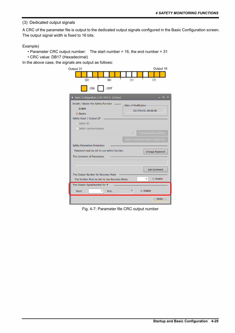
4.4 Safety Logic Edit 4.4.1 Safety input settings The safety logic edit function enables configuring conditions to start the safety monitoring function. Associating input states of DSI Input, Area Input, Logic Input, and Mode Input with safety monitoring functions to start enables switching safety monitoring items according to the input states. (Details on DSI Input, Area Input, Logic Input, and Mode Input are provided in this section.)
To configuring the settings, open the Safety Input screen from Workspace by selecting [Online] -> [Parameter] -> [Safety Parameter] -> [Safety option] -> [Safety Logic] -> [Safety Input (Safety IO)].
Fig. 4-16: Safety monitoring logic configuration screen
Tab. 4-2 Explanation of terminology
Category String Description See: Safety input state
DSIn (n = 1 to 8) DSI Input states (1)DSI Input AREAn (n = 1 to 3)
Area Input states (2)Area Input
LOGIC This outputs results of AND operation of DSIn inputs and AREAn inputs.
(3)Logic Input
MODE Mode selector switch states (4)Mode Input Safety monitoring command
SS1 SS1 command: Starts the SS1 function - SS2 SS2 command: Starts the SS2 function - SLSn (n = 1 to 3) SLSn command: Controls the start and end of
SLSn functions -
SLSM SLSM command: Controls the start and end of SLSM functions
-
SLPn (n = 1 to 3) SLPn command: Controls the start and end of SLPn functions
-
SLPM SLPM command: Controls the start and end of SLPM functions
-

4 SAFETY MONITORING FUNCTIONS
4-36 Safety Logic Edit
The matrix in the Safety Input screen has rows representing safety inputs (DSI, AREA, LOGIC, MODE). The columns represent safety monitoring start commands for each safety function (SS1, SS2, SLS1, SLS2, SLS3, SLSM, SLP1, SLP2, SLP3, SLPM). Checking intersections of the rows and columns defines safety functions started when the individual safety inputs are enabled. Example 1: To start the safely-limited speed function 1 (SLS1) when DSI2 is enabled, check the intersection of DSI2 and SLS1 as shown in Fig 4-17.
Fig 4-17: Example 1 of safety logic (safety input) configuration
Also, one safety input can start multiple safety functions. Example 2: Enabling DSI3 starts SLS1, SLS2, and SLP1 and enabling DSI4 starts SLS3.
Fig 4-18: Example 2 of safety logic (safety input) configuration

4 SAFETY MONITORING FUNCTIONS
Safety Logic Edit 4-37
(1) DSI Input
(a) Overview The DSI Input switches between the enabled state and disabled state depending on states of the duplex signals input into the SDI1 and SDI2 connectors of the safety extension unit. Input of up to eight points is supported.Tab. 4-3 shows the relation of the DSI Input to DSInA and DSInB.
Tab. 4-3: DSI Input states
DSI_A DSI_B Remarks DSIn input states (n = 1 to 8)
Enabled OFF OFF - ON OFF A 100-ms continuous discrepancy between
DSI_A and DSI_B will cause error H222: (DSI mismatch) and start SS1.
OFF ON
Disabled ON ON -
(b) Timing diagram ① Normal operation
ON
OFF
ON
OFF
有効
無効DSIn入力
DSInA
DSInB
Fig. 4-19: DSIn timing diagram
② When a discrepancy between DSInA and DSInB is detected If a discrepancy between DSInA and DSInB (n = 1 to 8) continues for 100 ms, error H222* (DSI mismatch) occurs.
ON
OFF
ON
OFF
有効
無効
有効
無効
(n=1-8)
DSIn入力
DSInA
DSInB
SS1指令
100ms
Fig. 4-20: DSIn timing diagram
Enabled Disabled
Enabled Disabled
DSIn input
SS1 command
Enabled Disabled
DSIn input

4 SAFETY MONITORING FUNCTIONS
4-38 Safety Logic Edit
(c) DSI filter configuration The DSI signal filtering can prevent wrong detection caused by chattering in the DSInA or DSInB signals or by test pulses from input devices. Enter a filter time in [DSI Filter Time] in the Safety Input screen.
Parameter Description Default DSI Filter Time A filter time for the DSI signals are
entered. The larger the setting is, the stronger the noise resistance becomes but the more the signal input detection is delayed. [Unit]: ms [Setting range]: 0 to 100
10ms
Fig. 4-21: DSI filter configuration
The DSI filter time and DSI1 input (enabled/disabled) are shown in the following diagram:
フィルタ時間 フィルタ時間
ONOFF
ONOFF
有効
無効DSIn入力
DSInA
DSInB
Fig. 4-22: Timing diagram of the DSI filter time and DSI1 input
DSIn input Enabled Disabled
Filter time Filter time

4 SAFETY MONITORING FUNCTIONS
Safety Logic Edit 4-39
(2) Area Input
(a) Overview AREA Input is a state that is enabled (or disabled) when the robot intrudes into or moves outside an area that is specified beforehand. Configuration of up to three areas is supported. The relation of the positions of the arm model and tool model, which are defined in Chapter 4.3 , to an area specified in this sub-section is monitored in real time, which switches AREA Input between the enabled and disabled states.
Fig. 4-23: Area input
(b) Timing diagram Intrusion of a monitoring position of the robot into a specified area enables the AREAn input.
設定したロボット位置 領域
有効無効
AREAn入力
Fig. 4-24: AREA Input timing diagram
Area 1
Enabled Disabled AREAn input
Robot position Specified
area

4 SAFETY MONITORING FUNCTIONS
4-40 Safety Logic Edit
(c) Configuring Area Input monitoring conditions Areas for area signals is configured in the Area Input screen. Selecting [Online] -> [Parameter] -> [Safety Parameter] -> [Safety option] -> [Safety Logic] -> [Area Input] from Workspace displays the Area Input screen.
Fig. 4-25: Area Input
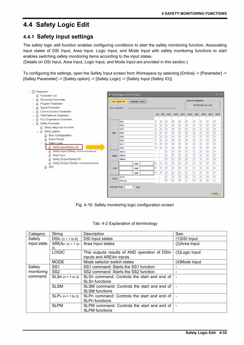
1) Area Input Configuration of up to three types of area input conditions is supported. From the pull-down menu of Area Input, select an area to configure. (Area 1 to 3) 2) Area Monitoring This sets the area monitoring to Enable or Disable. Selecting Disable results in no area judgment processing performed, always disabling Area Input. 3) Input Becomes on When Robot is • To enable Area Input when a monitoring position of the robot intrudes into the area, select [Inside of the Area]. • To enable Area Input when a monitoring position of the robot moves out of the area, select Outside of the Area. Both settings enable Area Input when a monitoring position of the robot comes into contact with the area. 4) Monitoring Position This specifies a monitoring position of the robot subject to the judgment of whether it is inside or outside of the monitored area. 5) Area Definition This specifies the monitored area. The area is defined as a cuboid parallel to a coordinate system formed from two points diagonal to each other. It is specified by the base coordinates system.
4 SAFETY MONITORING FUNCTIONS
Safety Logic Edit 4-41
Fig. 4-26: Area Input area Definition
(d) How to view the Area Input state
State variable M_SfIArea enables obtaining the Area Input state. The Operation Check screen for the safety input also enables viewing it.
Diagonal point 1 (X1,Y1,Z1)
Diagonal point 2 (X2,Y2,Z2)
Z
Y
X

4 SAFETY MONITORING FUNCTIONS
4-42 Safety Logic Edit
(3) Logic Input
(a) Overview Logic Input is a state enabled based on a combination of DSIn inputs (n = 1 to 8) and AREAm inputs (m = 1 to 3). It enables the AND condition of DSI and AREA to start the safety functions.
From Workspace, select [Online] -> [Parameter] -> [Safety Parameter] -> [Safety option] -> [Safety Logic] -> [Safety Input (Safety IO)] and open the Safety Input screen, which enables configuring of LOGIC (circled in red in the figure below).
The following is an example for inputting the SLS1 command when both DSI1 and AREA1 are enabled.
Fig. 4-27: Logic Input
(b) How to view the Logic Input state State variable M_Logic enables obtaining the Logic Input state. The Operation Check screen for the safety input also enables viewing it.
4 SAFETY MONITORING FUNCTIONS
Safety Logic Edit 4-43
(4) Mode Input
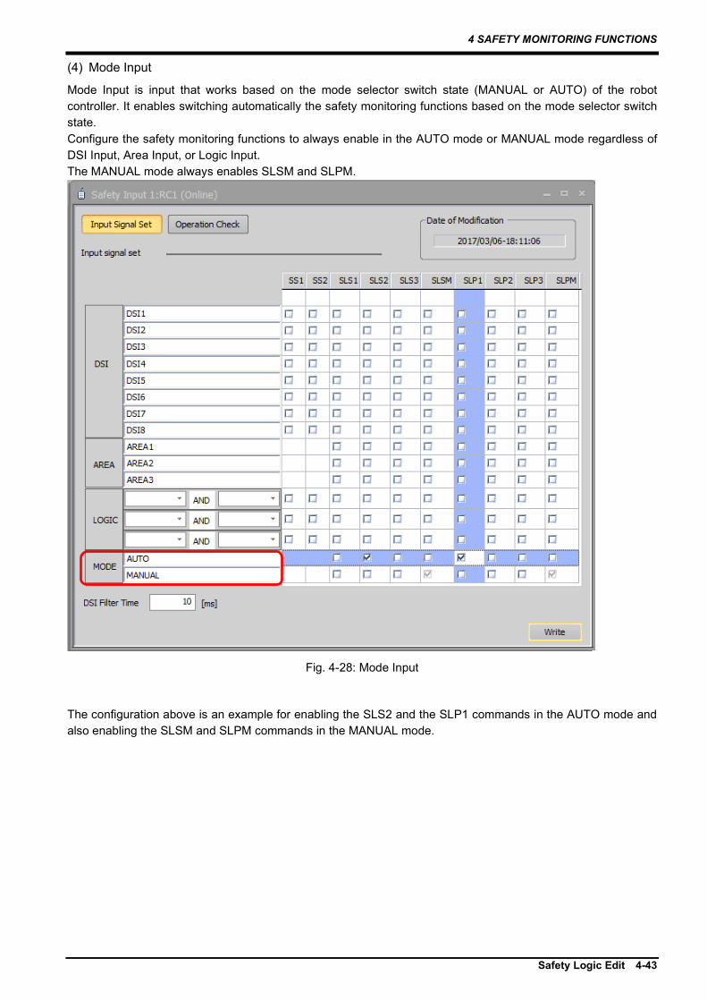
Mode Input is input that works based on the mode selector switch state (MANUAL or AUTO) of the robot controller. It enables switching automatically the safety monitoring functions based on the mode selector switch state. Configure the safety monitoring functions to always enable in the AUTO mode or MANUAL mode regardless of DSI Input, Area Input, or Logic Input. The MANUAL mode always enables SLSM and SLPM.
Fig. 4-28: Mode Input
The configuration above is an example for enabling the SLS2 and the SLP1 commands in the AUTO mode and also enabling the SLSM and SLPM commands in the MANUAL mode.
4 SAFETY MONITORING FUNCTIONS
4-44 Safety Logic Edit
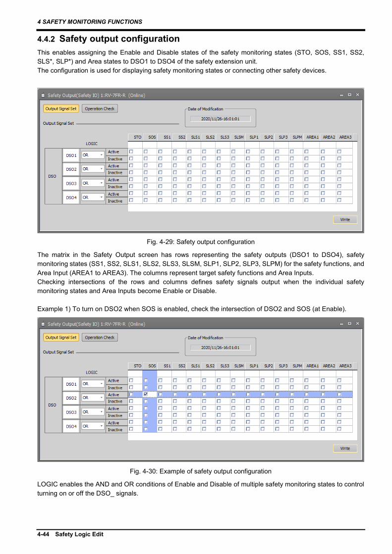
4.4.2 Safety output configuration This enables assigning the Enable and Disable states of the safety monitoring states (STO, SOS, SS1, SS2, SLS*, SLP*) and Area states to DSO1 to DSO4 of the safety extension unit. The configuration is used for displaying safety monitoring states or connecting other safety devices.
Fig. 4-29: Safety output configuration
The matrix in the Safety Output screen has rows representing the safety outputs (DSO1 to DSO4), safety monitoring states (SS1, SS2, SLS1, SLS2, SLS3, SLSM, SLP1, SLP2, SLP3, SLPM) for the safety functions, and Area Input (AREA1 to AREA3). The columns represent target safety functions and Area Inputs. Checking intersections of the rows and columns defines safety signals output when the individual safety monitoring states and Area Inputs become Enable or Disable. Example 1) To turn on DSO2 when SOS is enabled, check the intersection of DSO2 and SOS (at Enable).
Fig. 4-30: Example of safety output configuration
LOGIC enables the AND and OR conditions of Enable and Disable of multiple safety monitoring states to control turning on or off the DSO_ signals.

4 SAFETY MONITORING FUNCTIONS
Safety Logic Edit 4-45
Example 2) The following configuration is for outputting DSO1 when SLS1 is enabled and AREA1 disabled.
Fig. 4-31: Example of safety output configuration
Output settings for safety monitoring states SS1 and SS2 are supported by RT ToolBox3 Ver. 1.90U or later. To assign SS1 and SS2 to DSO outputs, use RT ToolBox3 Ver. 1.90U or later.
When SS1 and SS2 are assigned to DSO outputs, pressing [Write] on the Safety Output screen in RT ToolBox3 Ver. 1.82L or earlier will delete the assignments.
Caution
Caution

4 SAFETY MONITORING FUNCTIONS
4-46 Safety Logic Edit
4.4.3 Checking operation of the safety inputs and outputs After configuring the safety inputs and outputs, be sure to check that they operate as intended.
(1) How to check operation of the safety inputs
From Workspace, select [Online] -> [Parameter] -> [Safety Parameter] -> [Safety option] -> [Safety Logic] -> [Safety Input (Safety IO)] to open the Safety Input screen. Pressing the Operation Check button in this screen enables checking current states of the safety inputs and safety monitoring.
Fig. 4-32: Checking operation of the safety input
(2) How to check operation of the safety outputs
From Workspace, select [Online] -> [Parameter] -> [Safety Parameter] -> [Safety option] -> [Safety Logic] -> [Safety Output (Safety IO)] to open the Safety Output screen. Pressing the Operation Check button in this screen enables checking current states of the safety inputs and current states of safety monitoring.
Fig. 4-33: Checking operation of the safety output
4 SAFETY MONITORING FUNCTIONS
Safety Monitoring Functions 4-47
4.5 Safety Monitoring Functions This chapter provides the functional overview and configuration method of the safety monitoring function.
4.5.1 Safe torque off (STO) (1) Overview
This function electrically shuts off the motor driving energy according to input signals from external devices. It corresponds to stop category 0 of IEC60204-1.
(2) Operation sequence (a) STO start conditions
<SS1 command or emergency stop> To trigger the STO function, input the SS1 command or the emergency stop signal. Inputting the SS1 command or the emergency stop signal causes the robot to start decelerating and, after the robot stops safely, the STO function starts. For details on the sequence, see chapter 4.5.3 . (No external signal can directly start the STO function.) <When an error occurs> The STO function is triggered if:
・ The robot fails to stop within a deceleration monitoring period while SS1 is running. ・ The robot fails to stop within a deceleration monitoring period while SS2 is running ・ An internal error occurs which hinders the robot control ・ Communication with the safety extension unit fails
(b) Program operation state Program operation suspends during the STO monitoring. To resume, it is necessary to cancel all the SS1 start conditions and then perform program start operation. (c) Operation restrictions Operation restrictions during SS1/STO monitoring are shown in following table.
Tab. 4-4: Operation restrictions during SS1/STO monitoring
Operation Available Unavailable Remarks Servo-on Performing the servo-on operation
during the SS1/STO monitoring causes error H2270 (Servo-on prohibited during SS1/STO).
Program operation start The ALWAYS program does not stop. The ERROR program is not performed.
JOG operation Opening or closing hand For the TB operation only.
(3) Configuring monitoring conditions
There are no parameters concerning the STO function.

4 SAFETY MONITORING FUNCTIONS
4-48 Safety Monitoring Functions
4.5.2 Safe operating stop (SOS) (1) Overview
This is a function to keep shifts of the robot from the stop position within a specified value. This function provides the motors with driving energy necessary to keep the stop state. Change in the position or speed during the SOS monitoring causes error H2282 (SOS position error, SOS speed error).
(2) Operation sequence (a) SOS function start conditions
<SS2 command> To trigger the SOS function, input the SS2 command. Inputting the SS2 command causes the robot to start decelerating, and after the robot stops safely, the SOS function starts. For details on the sequence, see chapter 4.5.4 . (No external signal can directly start the SOS function.)
(b) Program operation state The SOS automatic resumption configuration enables changing the program operation state during the SOS monitoring.
Tab. 4-5: SOS automatic resumption mode
SOS automatic resumption (Disabled by factory default.)
Disabled Enabling the SS2 command during a program operation suspends the operation and causes no program start operation to be accepted. Resuming the program requires disabling the SS2 command and then performing program start operation.
Enabled Enabling the SS2 command during a program operation suspends the operation once a command concerning the robot movement is performed. Disabling the SS2 command automatically resumes the program operation.
(c) Operation restrictions
Operation restrictions during the SOS monitoring are shown in Table Tab. 4-6.
Tab. 4-6: Operation restrictions during the SOS monitoring
SOS automatic resumption disabled
SOS automatic resumption enabled
Operation Available Unavailable Available Unavailable Servo-on - - Servo-off Program operation start JOG operation Opening or closing hand
・ Turning off servos during the SOS monitoring disables the SOS monitoring. ・ When the SS2 command is enabled, turning on the servos again resumes the SOS monitoring.

4 SAFETY MONITORING FUNCTIONS
Safety Monitoring Functions 4-49
(d) When the robot moves during the SOS monitoring When one of the following items exceeds the allowable range during the SOS monitoring, the SS1 function stops the robot.
(i) Joint position command (ii) Joint position FB (iii) Joint speed command (iv) Joint speed FB
For (i) and (ii), the values are recorded at the beginning of the SOS monitoring and the judgments are made based on the differences between the values and the current ones.
関節速度指令関節速度FB
速度許容値0
関節位置指令関節位置FB
位置許容値
SOS監視開始時の位置有効無効
STO監視 有効
無効
SOS監視
Fig. 4-34: When the robot moves during the SOS monitoring
(e) When servos are turned off during the SOS monitoring
Turning off servos when the SS2 command is enabled disables the SS2 monitoring and the SOS monitoring. Turning on the servos again with the SS2 command enabled will enable the SOS monitoring 200 ms after the servos are turned on.
200ms
On
OFF
有効
無効
有効
無効
有効
無効SOS監視
サーボON/OFF
SS2指令
SS2監視
Fig. 4-35: When servos are turned off during the SOS monitoring
Joint speed command Joint speed FB
Joint position command Joint position FB
SOS monitoring
STO monitoring
Enabled Disabled
Enabled Disabled
Allowable speed
Allowable position
Position at the beginning of the SOS monitoring
Enabled Disabled
Enabled Disabled
Enabled Disabled
Servo-on/off
SS2 command
SS2 monitoring
SOS monitoring

4 SAFETY MONITORING FUNCTIONS
4-50 Safety Monitoring Functions
(3) Configuring monitoring conditions
Parameters related to the SOS function can be configured in the SOS screen, which can be opened by going to Workspace and selecting [Online] -> [Parameter] -> [Safety Parameter] -> [Safety option] -> [SOS].
Tab. 4-7: SOS related parameters
Setting item Description Default Safe stop speed This configures speed monitoring thresholds for
the SOS monitoring. 1.00 [deg./s] [mm/s]
Safe stopping distance
This configures allowable travel distances for the SOS monitoring.
1.00 [deg.] [mm]
SOS automatic resumption mode
This sets the SOS automatic resumption mode to Enable or Disable. Selecting Enable leads the program to automatically resume when the SOS monitoring is disabled. For details, refer to Tab. 4-5: SOS automatic resumption mode.
Disabled
Fig. 4-36: Configuring monitoring conditions

4 SAFETY MONITORING FUNCTIONS
Safety Monitoring Functions 4-51
4.5.3 Safe stop 1 (SS1) (1) Overview
The SS1 command input starts deceleration and, after the motors of all the axes decelerate below specified speeds or a specified time elapses, motor driving power is turned off (STO is started). (This function corresponds to stop category 1 of IEC60204-1.) Failure in deceleration within a specified maximum delay causes error H2280 (SS1 deceleration timeout).
(2) Operation sequence (a) SS1 command (Normal operation) The operation sequence of the SS1 function is as follows. The SS1 function is triggered when one of the following situations occurs during the robot operation.
• The SS1 command is entered. • The emergency stop is input.
• An H level error occurs. When the SS1 function is triggered, the deceleration starts at a specified deceleration rate. After the speed command becomes zero, the brakes are locked and STO shuts off the power supply to the servo motors. Canceling the trigger conditions restores the normal operation state.
速度 SS1 STO
フィードバック
指令
時間
0r/min
減速遅延時間
有効
無効
有効
無効
有効
無効
ブレーキ 解除
ロック
モータ電源供給 ON
OFF
速度
SS1指令
SS1監視
STO監視
安全停止速度
7.1ms
Fig. 4-37: SS1 command (Normal operation)
<Program operation state> Program operation suspends during the SS1 or STO monitoring. To resume it, it is necessary to cancel all the SS1 start conditions and then perform the program start operation.
Speed
Safe stop speed Speed Command
Feedback
Time
Deceleration delay
SS1 command
SS1 monitoring
STO monitoring
Brake
Motor power supply
Enabled Disabled
Enabled Disabled
Enabled Disabled
Released Locked

4 SAFETY MONITORING FUNCTIONS
4-52 Safety Monitoring Functions
(b) When deceleration fails with SS1 enabled Elapsed time from when the SS1 command is enabled is measured. If the motors fail to stop by the time the SS1 deceleration monitoring time elapses, error H2280 occurs. The operation sequence is shown below:
速度 SS1 STO
フィードバック
指令
時間
減速遅延時間
有効
無効
有効
無効
有効
無効
有効
無効
SS1エラー
(H2280)
速度
SS1指令
SS1監視
STO監視
安全停止速度
Fig. 4-38: When deceleration fails with SS1 enabled
(c) When the SS1 command is canceled with SS1 enabled before the STO monitoring state becomes
active Once the SS1 command is enabled, the SS1 monitoring cannot be canceled until the STO monitoring state becomes active (the deceleration and stop operation cannot be canceled). After the STO monitoring state becomes active, the SS1 monitoring is canceled.
速度 SS1 STO
フィードバック
指令
時間
減速遅延時間
有効
無効
有効
無効
有効
無効STO監視
速度指令
SS1指令
SS1監視
安全停止速度
Fig. 4-39: When the SS1 command is canceled with SS1 enabled before the STO monitoring state becomes
active
(d) When the origin has not been configured When the origin has not been configured, inputting the SS1 command (emergency stop, error) activates the STO monitoring state immediately.
Speed
Safe stop speed Speed
Command Feedback
Time
Deceleration delay
SS1 command
SS1 monitoring
STO monitoring
Enabled Disabled
Enabled Disabled
Enabled Disabled
SS1 error Enabled Disabled
Speed
Safe stop speed Command
Feedback
Time
Deceleration delay
SS1 command
SS1 monitoring
STO monitoring
Enabled Disabled
Enabled Disabled
Enabled Disabled
Speed command

4 SAFETY MONITORING FUNCTIONS
Safety Monitoring Functions 4-53
(3) Configuring monitoring conditions
(a) Safe stop speed In Workspace, open the SOS screen by selecting [Online] -> [Parameter] -> [Safety Parameter] -> [Safety option] -> [SOS]. Then, in the Stop Speed items, enter speeds at which the motors are judged to have stopped. These settings are shared by the SS1, SS2, and SOS functions.
Fig. 4-40: Safe stop speed
(b) Deceleration monitoring time Deceleration monitoring time differs from model to model. Deceleration monitoring time cannot be changed.

4 SAFETY MONITORING FUNCTIONS
4-54 Safety Monitoring Functions
4.5.4 Safe stop 2 (SS2) (1) Overview
The SS2 command input starts deceleration and, after the motors of all the axes decelerate below specified speeds, SOS is started. (This function corresponds to stop category 2 of IEC60204-1.) Failure in deceleration within a specified maximum delay causes error H2281 (SS2 deceleration timeout).
(2) Operation sequence (a) SS2 command (Normal operation) The operation sequence of the SS2 function is as follows. Enabling the SS2 command while the robot is in operation starts the SS2 function. The triggered SS2 starts deceleration at a specified deceleration rate. After the speed command reaches the safety speed, SOS starts position monitoring with servo-on state kept. Disabling the SS2 command restores the normal operation state.
速度 SS2 SOS
フィードバック
指令
時間
0r/min
減速遅延時間
有効
無効
有効
無効
有効
無効
ブレーキ 解除
ロック
モータ電源供給 ON
OFF
速度
SS2指令
SS2監視
SOS監視
安全停止速度
Fig. 4-41: SS2 command (Normal operation)
Speed
Safe stop speed Speed
Command Feedback
Time
Deceleration delay
SS2 command
SS2 monitoring
SOS monitoring
Brake
Motor power supply
Enabled Disabled
Enabled Disabled
Enabled Disabled
Released Locked

4 SAFETY MONITORING FUNCTIONS
Safety Monitoring Functions 4-55
(b) When the motors fail to decelerate within monitoring time with SS2 enabled Time is measured after the SS2 command is enabled. If the motors fail to stop by the time the SS2 deceleration monitoring time elapses, error H2281 occurs and STO shuts off the driving power. The operation sequence is shown below:
速度 SS2 STO
フィードバック
指令
時間
減速遅延時間
有効
無効
有効
無効
有効
無効
有効
無効
SS2エラー
(H2281)
速度
SS2指令
SS2監視
STO監視
安全停止速度
Fig. 4-42: When the motors fail to decelerate within monitoring time with SS2 enabled
(c) When the SS2 command is disabled before the motors stop with SS2 enabled Once the SS2 command is enabled, the SS2 monitoring cannot be canceled until the SOS monitoring state becomes active (the deceleration and stop operation cannot be canceled). After the SOS state becomes active, the SS2 monitoring is canceled.
速度 SS2 SOS
フィードバック
指令
時間
減速遅延時間
有効
無効
有効
無効
有効
無効SOS監視
速度指令
SS2指令
SS2監視
安全停止速度
Fig. 4-43: When the SS2 command is disabled before the motors stop with SS2 enabled
Speed
Safe stop speed Speed
Command Feedback
Time
Deceleration delay
SS2 command
SS2 monitoring
STO monitoring
Enabled Disabled
Enabled Disabled
Enabled Disabled
SS2 error Enabled Disabled
Speed
Safe stop speed Speed command
Command Feedback
Time
Deceleration delay
SS2 command
SS2 monitoring
SOS monitoring
Enabled Disabled
Enabled Disabled
Enabled Disabled
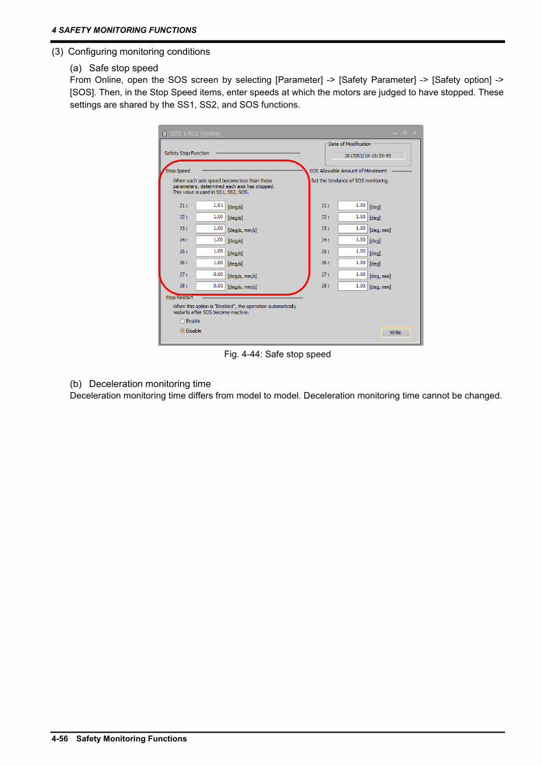
4 SAFETY MONITORING FUNCTIONS
4-56 Safety Monitoring Functions
(3) Configuring monitoring conditions
(a) Safe stop speed From Online, open the SOS screen by selecting [Parameter] -> [Safety Parameter] -> [Safety option] -> [SOS]. Then, in the Stop Speed items, enter speeds at which the motors are judged to have stopped. These settings are shared by the SS1, SS2, and SOS functions.
Fig. 4-44: Safe stop speed
(b) Deceleration monitoring time Deceleration monitoring time differs from model to model. Deceleration monitoring time cannot be changed.

4 SAFETY MONITORING FUNCTIONS
Safety Monitoring Functions 4-57
4.5.5 Safely-limited speed function (SLS) (1) Overview
This is a function to monitor the robot and the robot tool speeds so that they are under specified speed limits. When they are above a speed limit, the SS1 function stops the robot. Configuration of up to four different types (SLS1, SLS2, SLS3, SLSM) of speed monitoring conditions are supported. During SLS monitoring, the devices move at speeds specified in Speed Limit OVRD.
(2) Operation sequence (a) SLS_ function basic operation Enabling the SLS_ command starts the SLS function. The moment the SLS_ command is enabled, deceleration starts at rates specified in Speed Limit OVRD and, after the deceleration monitoring time elapses, the speed monitoring (SLS monitoring) starts.
Tab. 4-8: SLS function start conditions
Function Functional condition
Description
SLS1 SLS1 command input
When the signal assigned to the SLS1 command is input
SLS2 SLS2 command input
When the signal assigned to the SLS2 command is input
SLS3 SLS3 command input
When the signal assigned to the SLS3 command is input
SLSM SLSM command input
When the signal assigned to the SLSM command is input
速度 SLS
フィードバック指令
時間
減速監視時間
有効無効
有効無効
SLS_監視
SLS_指令
SLS監視速度
速度指令
速度フィードバック
Fig. 4-45: SLS_ function basic operation
Speed
SLS monitoring speed
Speed command Speed feedback
Command Feedback
Time
Deceleration monitoring time
SLS_ command
SLS_ monitoring
Enabled Disabled
Enabled Disabled

4 SAFETY MONITORING FUNCTIONS
4-58 Safety Monitoring Functions
(b) When a specified speed limit is exceeded during the SLS_ monitoring Detection of a speed command or speed feedback exceeding the monitoring speed during the SLS_ monitoring causes error 230* (Abnormal SLS joint speed) or error 231* (Abnormal SLS orthogonal speed). The operation sequence is shown in the figure below:
速度 SLS
フィードバック指令
時間
減速監視時間
有効無効
有効無効
有効
有効
SLS_監視
SLS_指令
SS1指令
SLS監視速度
速度指令
速度フィードバック
Fig. 4-46: When a specified speed limit is exceeded during the SLS_ monitoring
(c) When the devices fail to decelerate within a specified time with SLS enabled With SLS enabled, if the SLS monitoring speed limit is exceeded or the devices fail to decelerate to the monitoring speed within the SLS deceleration time, error H230* (Abnormal SLS joint speed) or error H231* (Abnormal SLS orthogonal speed) occurs and the SS1 function stops the devices. The errors occur when the limit overrides are too large or the deceleration monitoring time is too short.
速度 SLS SS1/STO
フィードバック指令
時間
減速監視時間
有効無効
有効無効
ON(有効)
OFF(無効)
SLS_監視
SLS_指令
SS1指令
速度指令速度フィードバック SLS監視速度
Fig. 4-47: When the devices fail to decelerate within a specified time with SLS enabled
Deceleration monitoring time
Feedback
Speed
SLS monitoring speed
Speed command Speed feedback
Command Feedback
Time
Deceleration monitoring time
SLS_ command
SLS_ monitoring
Enabled Disabled
Enabled Disabled
Enabled Enabled
SS1 command
Speed
Speed command Speed feedback Command
Time
SLS_ command
SLS_ monitoring
Enabled Disabled
Enabled Disabled
ON (Enabled) OFF (Disabled)
SS1 command
SLS monitoring speed

4 SAFETY MONITORING FUNCTIONS
Safety Monitoring Functions 4-59
(d) Operation with the servos on or off When the servos are off, the SLS monitoring is disabled. The SLS monitoring is enabled 200 ms after the servos are turned on.
200ms
ONOFF
有効無効
有効無効
サーボON/OFF
SLS指令
SLS監視
Fig. 4-48: Operation with the servos on or off
(e) When multiple SLS commands are input simultaneously When multiple SLS commands are input simultaneously, the monitoring is performed based on all the enabled monitoring speeds. The limit override applicable in this case is the smallest one of the values for the SLS functions.
SLS速度1 SLS速度2
有効無効
有効無効
有効無効
有効
無効SLS2監視
SLS1監視中
SLS2指令
SLS1監視
速度
SLS1指令
減速監視時間
減速監視時間
SLS2監視中
Fig. 4-49: When multiple SLS commands are input simultaneously
SLS command
SLS monitoring
Enabled Disabled
Enabled Disabled
Servo-on/off
SLS1 command
SLS1 monitoring
Enabled Disabled
Enabled Disabled
Speed
SLS1 monitoring in operation
SLS speed 1 SLS speed 2
SLS2 monitoring
SLS2 command
Enabled Disabled
Enabled Disabled
SLS2 monitoring in operation
Deceleration monitoring time
Deceleration monitoring time
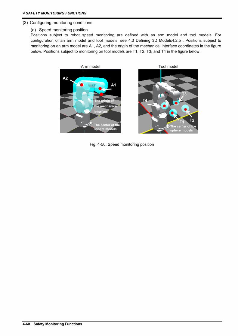
4 SAFETY MONITORING FUNCTIONS
4-60 Safety Monitoring Functions
(3) Configuring monitoring conditions
(a) Speed monitoring position Positions subject to robot speed monitoring are defined with an arm model and tool models. For configuration of an arm model and tool models, see 4.3 Defining 3D Models4.2.5 . Positions subject to monitoring on an arm model are A1, A2, and the origin of the mechanical interface coordinates in the figure below. Positions subject to monitoring on tool models are T1, T2, T3, and T4 in the figure below.
Fig. 4-50: Speed monitoring position
Arm model Tool model
A1 A2
The origin of the mechanical interface
T1 T2
T3 T4
The center of the sphere models
The center of the sphere models

4 SAFETY MONITORING FUNCTIONS
Safety Monitoring Functions 4-61
(b) Monitoring speed limits There are two modes available for configuration of the SLS monitoring speeds: Simple Mode and Detail Mode. Detail Mode enables detailed configuration of allowable speeds. Besides synthesized speeds, it allows monitoring of speeds of X, Y, Z components and joint angular speeds.
Tab. 4-9: Items available for monitoring in each SLS mode
Monitoring items Configuration mode
Setting range
Simple Detail Orthogonal speed limit
Arm model Tool model Mechanical I/F
composite speed
0 mm/s to 100000 mm/s (0 to 250 mm/s for SLSM) +X speed
-X speed +Y speed -Y speed +Z speed -Z speed
Joint speed limit Joint axes J1 to J6
J1 speed 0% to 100% (Configure a ratio to the maximum speed.)
J2 speed J3 speed J4 speed J5 speed J6 speed
Additional axis J7 to J8
J7 speed J8 speed
From Workspace of RT ToolBox3, open the Speed screen by selecting [Online] -> [Parameter] -> [Safety Parameter] -> [Safety option] -> [SLS] -> [Speed] and configure the speed limits.
Fig. 4-51: Simple mode of monitoring speed limits
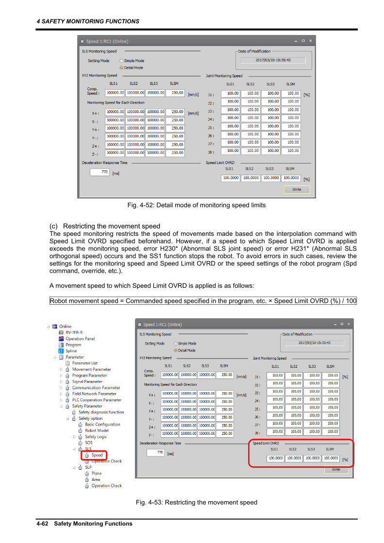
4 SAFETY MONITORING FUNCTIONS
4-62 Safety Monitoring Functions
Fig. 4-52: Detail mode of monitoring speed limits
(c) Restricting the movement speed The speed monitoring restricts the speed of movements made based on the interpolation command with Speed Limit OVRD specified beforehand. However, if a speed to which Speed Limit OVRD is applied exceeds the monitoring speed, error H230* (Abnormal SLS joint speed) or error H231* (Abnormal SLS orthogonal speed) occurs and the SS1 function stops the robot. To avoid errors in such cases, review the settings for the monitoring speed and Speed Limit OVRD or the speed settings of the robot program (Spd command, override, etc.). A movement speed to which Speed Limit OVRD is applied is as follows: Robot movement speed = Commanded speed specified in the program, etc. × Speed Limit OVRD (%) / 100
Fig. 4-53: Restricting the movement speed
4 SAFETY MONITORING FUNCTIONS
Safety Monitoring Functions 4-63
Restriction on the commanded speed by Speed Limit OVRD is effective for the speed of movements made by the interpolation command. The restriction is not effective for the correction speed generated by the compliance control, force sense control, or tracking function. While these functions are executed, an error may occur depending on the settings for operation or monitoring speed.
Speed Limit OVRD is not effective for the movement speed under real-time external control (Mxt command). Correct the commanded position according to the monitoring speed on the commanded position generation side.
(d) Deceleration monitoring time This field is for configuring wait time from when the SLS command is enabled to when monitoring starts. When a speed is above an allowable speed after the wait time elapses, an error occurs.
Caution
Caution

4 SAFETY MONITORING FUNCTIONS
4-64 Safety Monitoring Functions
(4) Operation check
The following shows how to check that the monitoring speed is configured correctly.
(a) How to check the SLS monitoring state From Workspace, open the Operation Check screen by selecting [Online] -> [Parameter] -> [Safety Parameter] -> [Safety option] -> [SLS] -> [Operation Check] and check the SLS monitoring state and speed measurement values. The measurement value fields hold the maximum values of speed feedback for individual monitoring positions. The reset button clears the maximum values.
Fig. 4-54: How to check the SLS monitoring state

4 SAFETY MONITORING FUNCTIONS
Safety Monitoring Functions 4-65
4.5.6 Safely-limited position function (SLP) (1) Overview
This function defines safeguarded spaces around the robot that restrict intrusion of the robot into them and monitors the robot arm and tools so that they do not enter the spaces. If the robot gets close to a safeguarded space during operation, the robot stops. When a monitoring position passes through the position monitoring plane into a safeguarded space, error H220m (m: plane or area number) occurs and the SS1 function will stop the robot.
Fig. 4-55: Safely-limited position function
This function does not guarantee that the robot arm and tools will not enter the safeguarded spaces.
(2) Operation sequence (a) SLP_ function basic operation Enabling a SLP_ command (SLP1, SLP2, SLP3, or SLPM command) triggers the SLP function.
SLP 監視領域
有効無効
有効無効
SLP 監視
SLP_監視
SLP_指令
ロボット位置
Fig. 4-56: SLP_ function basic operation
SLP_ command Enabled Disabled
Robot position SLP
monitoring area
SLP monitoring
SLP_ monitoring Enabled Disabled
Caution
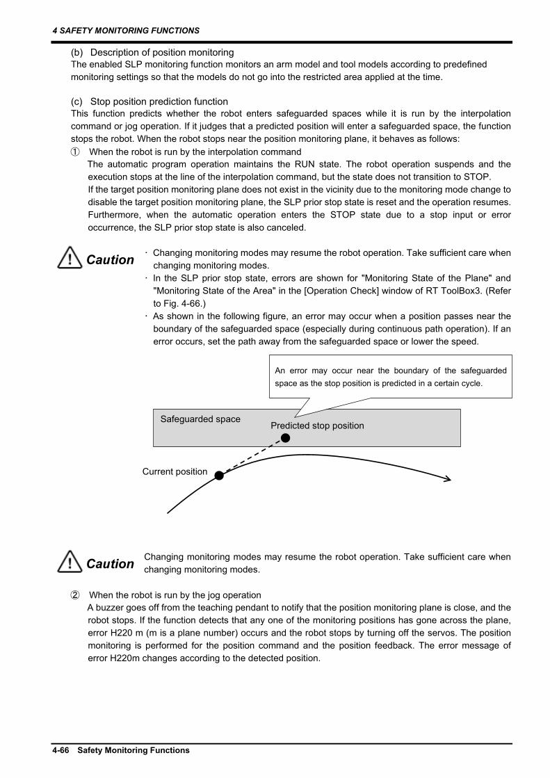
4 SAFETY MONITORING FUNCTIONS
4-66 Safety Monitoring Functions
(b) Description of position monitoring The enabled SLP monitoring function monitors an arm model and tool models according to predefined monitoring settings so that the models do not go into the restricted area applied at the time.
(c) Stop position prediction function This function predicts whether the robot enters safeguarded spaces while it is run by the interpolation command or jog operation. If it judges that a predicted position will enter a safeguarded space, the function stops the robot. When the robot stops near the position monitoring plane, it behaves as follows: ① When the robot is run by the interpolation command
The automatic program operation maintains the RUN state. The robot operation suspends and the execution stops at the line of the interpolation command, but the state does not transition to STOP. If the target position monitoring plane does not exist in the vicinity due to the monitoring mode change to disable the target position monitoring plane, the SLP prior stop state is reset and the operation resumes. Furthermore, when the automatic operation enters the STOP state due to a stop input or error occurrence, the SLP prior stop state is also canceled.
・ Changing monitoring modes may resume the robot operation. Take sufficient care when changing monitoring modes.
・ In the SLP prior stop state, errors are shown for "Monitoring State of the Plane" and "Monitoring State of the Area" in the [Operation Check] window of RT ToolBox3. (Refer to Fig. 4-66.)
・ As shown in the following figure, an error may occur when a position passes near the boundary of the safeguarded space (especially during continuous path operation). If an error occurs, set the path away from the safeguarded space or lower the speed.
Changing monitoring modes may resume the robot operation. Take sufficient care when changing monitoring modes.
② When the robot is run by the jog operation
A buzzer goes off from the teaching pendant to notify that the position monitoring plane is close, and the robot stops. If the function detects that any one of the monitoring positions has gone across the plane, error H220 m (m is a plane number) occurs and the robot stops by turning off the servos. The position monitoring is performed for the position command and the position feedback. The error message of error H220m changes according to the detected position.
Safeguarded space
Current position
Predicted stop position
An error may occur near the boundary of the safeguarded space as the stop position is predicted in a certain cycle.
Caution
Caution

4 SAFETY MONITORING FUNCTIONS
Safety Monitoring Functions 4-67
SLP 監視ロボット位置 領域
予測位置実際位置
有効無効
有効無効
SLP_エラー エラー
エラー無し
SLP事前停止 有効
無効
SLP
SLP_監視
SLP_指令
Fig. 4-57: Stop position prediction function
The function to stop the movement near the position monitoring plane works for operation commands concerning the interpolation command or the jog operation. The function does not work for correction commands of the compliance control, force sense control, or tracking function. Therefore, stopping operation commands near the position monitoring plane while these functions are running may not prevent the robot from reaching the position monitoring plane due to correction commands, causing an error.
③ When error H220m occurs in the SLP prior stop state
Depending on the monitoring position settings or how the robot is moving, a monitoring position may enter a safeguarded space in the SLP prior stop state, causing error H220m. Setting a margin between the predicted stop position and the safeguarded space prevents error H220m from occurring. Use SPPFMG parameter to set the margin.
Table 4-10: Margin between the predicted stop position and the safeguarded space
Item Description Parameter name SPPFMG Function Set a margin between the predicted stop position and the
safeguarded space to prevent error H220m from occurring in the SLP prior stop state.
What parameter settings means
Margin (distance) between the predicted stop position and the safeguarded space
Setting range 0.00 to 1000.00 (unit: mm) Default 0.00
When the margin is set using SPPFMG parameter, the robot will stop before entering the safeguarded space (SLP prior stop) according to the setting value. A monitoring position will not enter the safeguarded space and thus error H220m will not occur.
Caution
SLP_ command Enabled Disabled
Robot position
SLP monitoring
area
Enabled Disabled
Enabled Disabled
Predicted position Actual position
SLP_ monitoring
SLP_ error Error No error
SLP prior stop
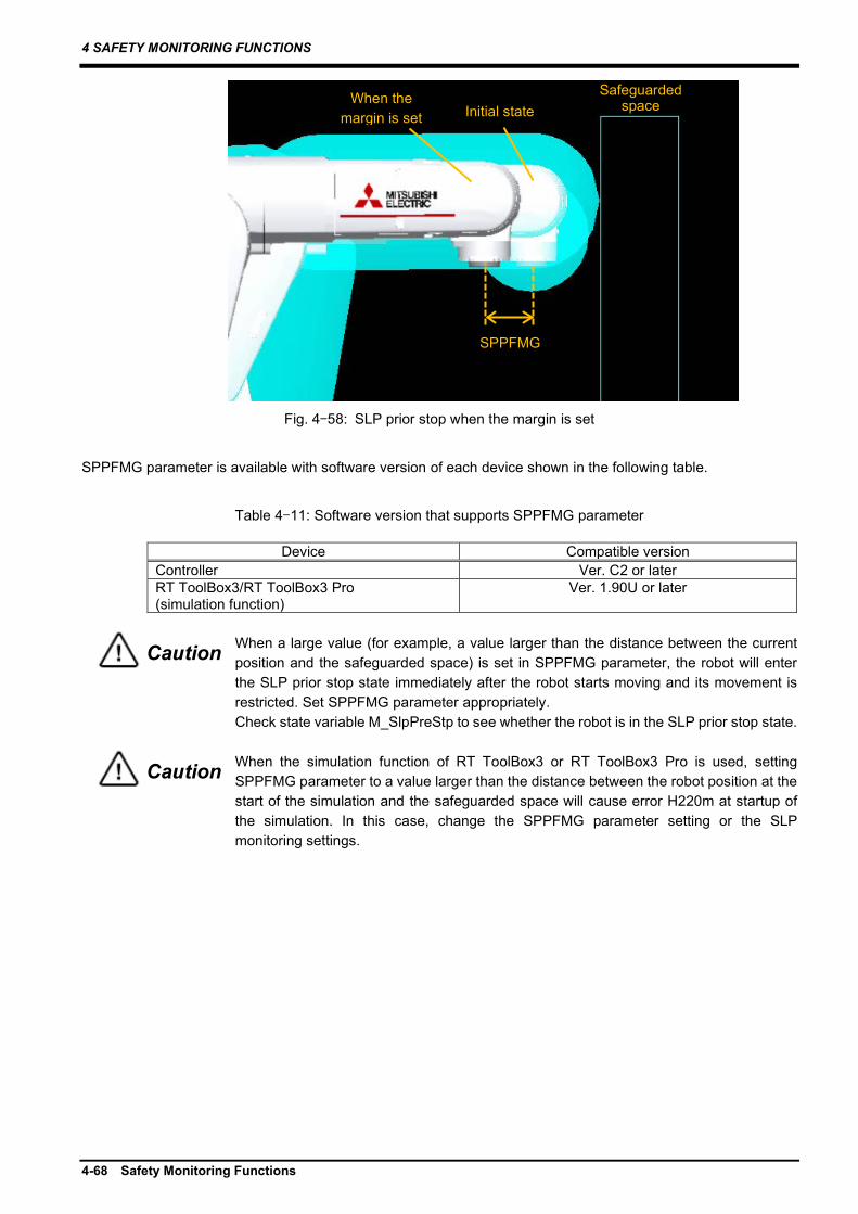
4 SAFETY MONITORING FUNCTIONS
4-68 Safety Monitoring Functions
Fig. 4-58: SLP prior stop when the margin is set
SPPFMG parameter is available with software version of each device shown in the following table.
Table 4-11: Software version that supports SPPFMG parameter
Device Compatible version Controller Ver. C2 or later RT ToolBox3/RT ToolBox3 Pro (simulation function)
Ver. 1.90U or later
When a large value (for example, a value larger than the distance between the current position and the safeguarded space) is set in SPPFMG parameter, the robot will enter the SLP prior stop state immediately after the robot starts moving and its movement is restricted. Set SPPFMG parameter appropriately. Check state variable M_SlpPreStp to see whether the robot is in the SLP prior stop state.
When the simulation function of RT ToolBox3 or RT ToolBox3 Pro is used, setting SPPFMG parameter to a value larger than the distance between the robot position at the start of the simulation and the safeguarded space will cause error H220m at startup of the simulation. In this case, change the SPPFMG parameter setting or the SLP monitoring settings.
Safeguarded space Initial state
When the margin is set
SPPFMG
Caution
Caution
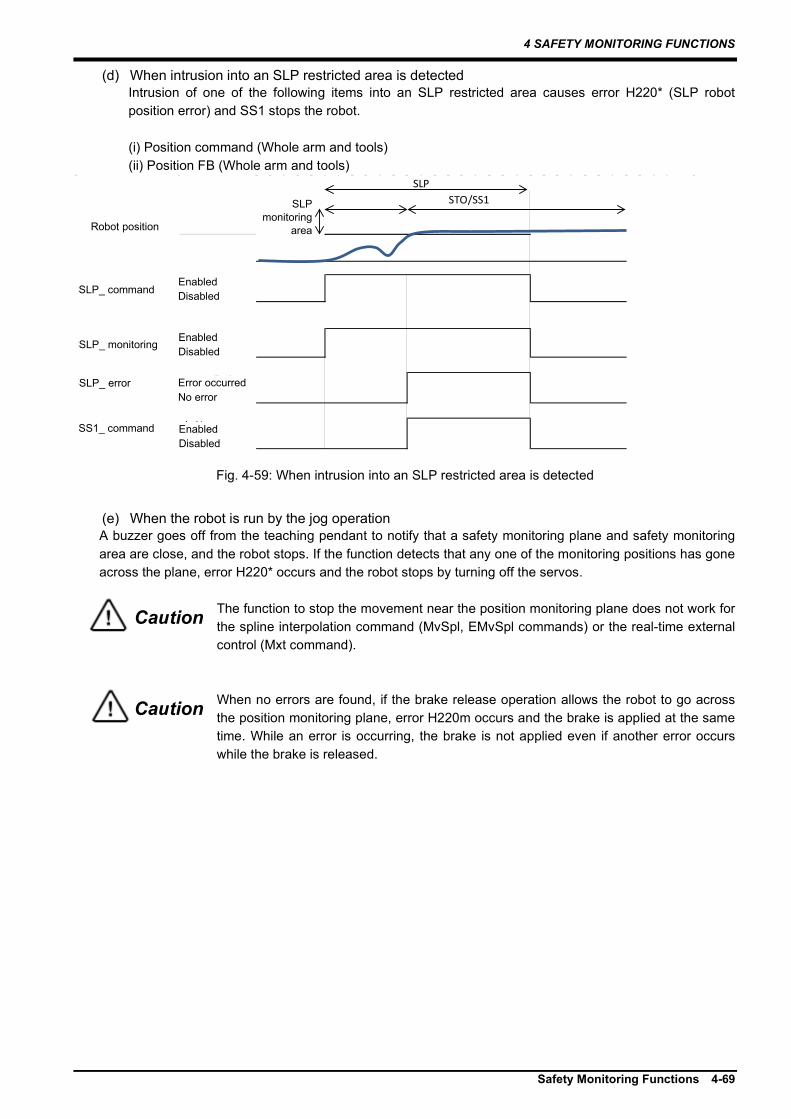
4 SAFETY MONITORING FUNCTIONS
Safety Monitoring Functions 4-69
(d) When intrusion into an SLP restricted area is detected Intrusion of one of the following items into an SLP restricted area causes error H220* (SLP robot position error) and SS1 stops the robot.
(i) Position command (Whole arm and tools) (ii) Position FB (Whole arm and tools)
SLP 監視ロボット位置 領域
有効無効
有効無効
SLP_エラー エラー発生
エラー無し
SS1_指令 有効
無効
SLP
SLP_監視
STO/SS1
SLP_指令
Fig. 4-59: When intrusion into an SLP restricted area is detected
(e) When the robot is run by the jog operation A buzzer goes off from the teaching pendant to notify that a safety monitoring plane and safety monitoring area are close, and the robot stops. If the function detects that any one of the monitoring positions has gone across the plane, error H220* occurs and the robot stops by turning off the servos.
The function to stop the movement near the position monitoring plane does not work for the spline interpolation command (MvSpl, EMvSpl commands) or the real-time external control (Mxt command).
When no errors are found, if the brake release operation allows the robot to go across the position monitoring plane, error H220m occurs and the brake is applied at the same time. While an error is occurring, the brake is not applied even if another error occurs while the brake is released.
Caution
Caution
SLP_ command Enabled Disabled
Robot position
SLP monitoring
area
Enabled Disabled
Enabled Disabled
SLP_ monitoring
SLP_ error Error occurred No error
SS1_ command

4 SAFETY MONITORING FUNCTIONS
4-70 Safety Monitoring Functions
(3) Configuring monitoring conditions
(a) Arm model and tool model Monitoring targets can be configured as a sphere model or cylinder model fixed to the robot or hand. Change in an arm model can only be made to the size. For tool models, free configuration of up to four sphere models is supported. For configuration of robot monitoring positions and hand monitoring positions, see 4.3 Defining 3D Models.
(b) Safety monitoring plane
SLP monitoring planes for position monitoring can be configured. Definition of up to eight planes is supported.
Fig. 4-60: Safety monitoring plane
① Plane Setting This enables selecting a monitoring plane to be configured or changed from the pull-down menu. (Plane 1 to Plane 8)
② Plane Monitoring
This sets the plane monitoring to Enable or Disable. Only the planes set to Enable are monitored.
③ Safeguarded Space This specifies the side of a monitoring plane on which the safeguarded space (that allows no movement) is placed. To set the safeguarded space on the opposite side of the origin of the robot, select Outside. To set the safeguarded space on the side of the origin of the robot, select Inside. (See the figure below.)
Fig. 4-61: Safeguarded space setting
Safeguarded Space
Space allowing movement
[Outside setting]
Monitored plane
[Inside setting]
Space allowing movement
Safeguarded Space
Monitored plane

4 SAFETY MONITORING FUNCTIONS
Safety Monitoring Functions 4-71
④ Monitoring Position This enables selecting a monitoring position of the robot subject to position monitoring.
Selecting [Whole Arm and Tool] enables the position monitoring that uses an arm model and tool models defined in 4.3 Defining 3D Models. Selecting [Tool Only] enables the position monitoring that only monitors tool models.
⑤ Monitoring Function To Apply the Plane This enables selecting monitoring functions (SLP1, SLP2, SLP3, SLPM) to which the monitoring plane is applied. Multiple functions can be selected.
⑥ Plane Definition As shown in the right figure, configure X, Y, Z coordinates of the three points (origin, +X axis position, +Y axis direction) on the defined plane in the base coordinate system. The plane is defined in the base coordinate system. Therefore, the base conversion does not change the relative position of the robot to the position monitoring plane. <Base coordinate system> The base coordinate system is a coordinate system based on the robot installation surface. The center of the robot installation position (base data) in the world coordinate system can be changed by using parameter MEXBS or executing the Base command. By default, the world coordinate system and the base coordinate system are placed at the same position.
Fig. 4-62: Plane Definition
Fig. 4-63: Base coordinate system
Origin
Position on +X axis
+Yaxis direction
Base coordinate system
World coordinate system
Base data

4 SAFETY MONITORING FUNCTIONS
4-72 Safety Monitoring Functions
(c) Safety monitoring area This enables configuring safety monitoring areas. Definition of up to eight areas is supported.
Fig. 4-64: Safety monitoring area
① Area Setting Definition of up to eight areas is supported. Select a monitoring area (Area 1 to Area 8) to be changed or edited from the pull-down menu.
② Area Monitoring
This sets the area monitoring to Enable or Disable. Only the areas set to Enable are monitored.
③ Safeguarded Space This specifies whether the safeguarded area (into which the robot cannot intrude) is inside or outside the area.
④ Monitoring Position
This enables selecting a monitoring position of the robot subject to position monitoring.
⑤ Monitoring Function To Apply the Area This enables selecting monitoring functions (SLP1, SLP2, SLP3, SLPM) to which the monitoring area is applied. Multiple functions can be selected.
⑥ Area Definition
This configures the monitoring area. As shown in the figure in the rignt, the area is defined as a cuboid parallel to a coordinate system formed from two points diagonal to each other. In the same way as a plane area, configure the coordinates of the diagonal points in the base coordinate system. The area is defined in the base coordinate system. Therefore, the base conversion does not change the relative position of the robot to the position monitoring plane.
Fig. 4-65: Area Definition
Diagonal point 1 (X1,Y1,Z1)
Diagonal point 2 (X2,Y2,Z2)
Z
Y
X
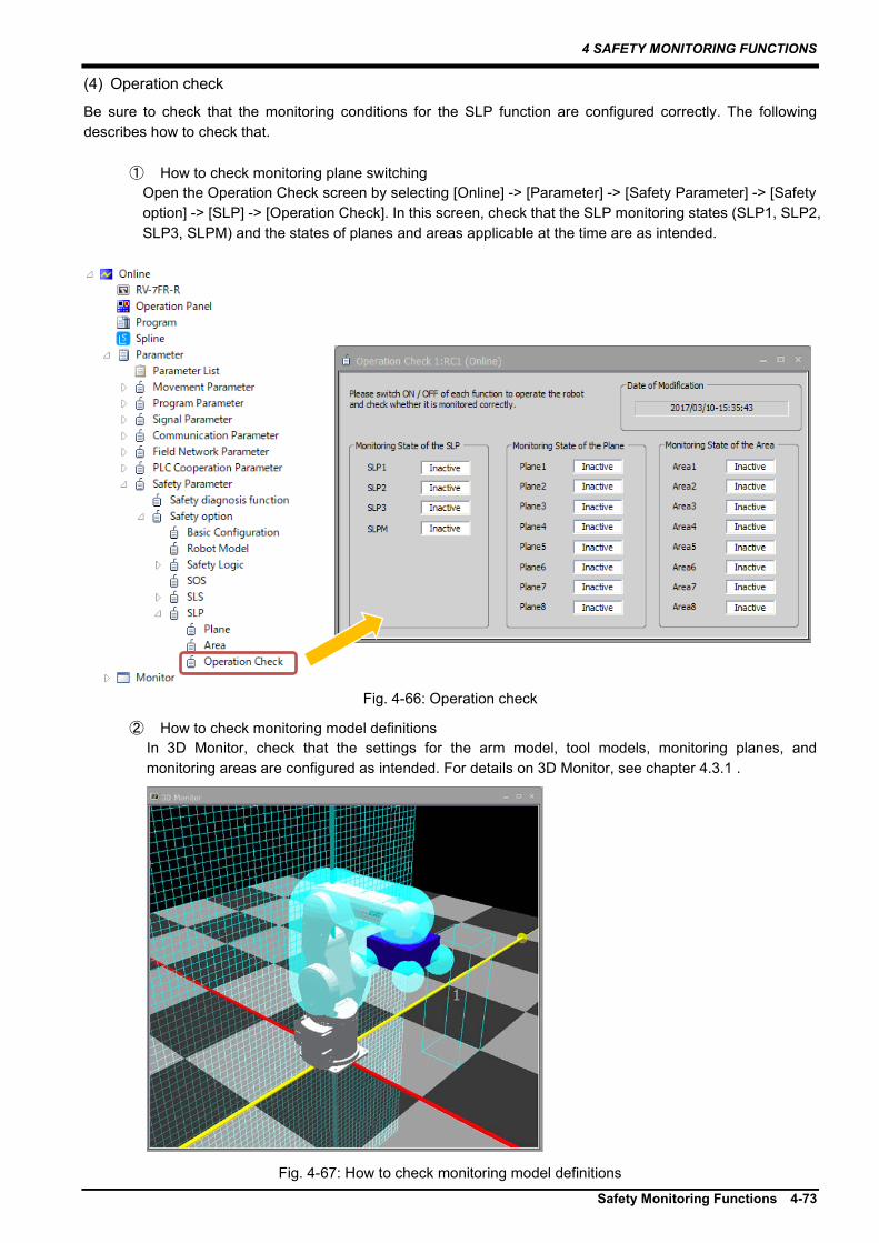
4 SAFETY MONITORING FUNCTIONS
Safety Monitoring Functions 4-73
(4) Operation check
Be sure to check that the monitoring conditions for the SLP function are configured correctly. The following describes how to check that.
① How to check monitoring plane switching Open the Operation Check screen by selecting [Online] -> [Parameter] -> [Safety Parameter] -> [Safety option] -> [SLP] -> [Operation Check]. In this screen, check that the SLP monitoring states (SLP1, SLP2, SLP3, SLPM) and the states of planes and areas applicable at the time are as intended.
Fig. 4-66: Operation check
② How to check monitoring model definitions In 3D Monitor, check that the settings for the arm model, tool models, monitoring planes, and monitoring areas are configured as intended. For details on 3D Monitor, see chapter 4.3.1 .
Fig. 4-67: How to check monitoring model definitions

4 SAFETY MONITORING FUNCTIONS
4-74 Safety Diagnosis Function
4.6 Safety Diagnosis Function 4.6.1 Test pulse diagnosis (EMG) This function enables diagnosis of external wiring by pulse signals output from the emergency stop ports (EXTEMG11, EXTEMG21). Changing parameter TPOEMG allows EXTEMG11 and EXTEMG21 to output off-pulses regularly. The width of output pulses is always approximately 20 ms. Checking regularly the test pulses inside the robot controller enables confirming the correct operation of the emergency stop lines. When an emergency stop signal triggers the SS1 function, use of this safety diagnosis function satisfies SIL3 and PLe/Category 4. When using this function, connect emergency stop switches by seeing Fig. 4-69. Make sure to prevent test pulses of this function from causing faulty operation of peripheral devices.
Fig. 4-68: Test pulse diagnosis
Tab. 4-12: Test pulse diagnosis
Item Description Parameter name TPOEMG Function This enables configuring the pulse output function for outputting test pulse
signals from emergency stop ports (EXTEMG11, EXTEMG21). What parameter settings means
0: Outputs no test pulses 1: Outputs test pulses
Default 0
ロボットコントローラ
CNUSR11
EXTEMG1114
30EXTEMG12
7
23EXTEMG22
EXTEMG21
非常停止スイッチ(2接点)
Fig. 4-69: How to wire emergency stop lines
EXTEMG11
Approx. 1000ms
Approx.20ms
Approx.20ms
Approx.40ms
EXTEMG21
Robot controller
Emergency stop switches (2 contacts)

5 STATE VARIABLE
List of State Variables 5-75
5. STATE VARIABLE States variable for the safety monitoring function are shown below:
5.1 List of State Variables Tab. 5-1: List of state variables
State variable Overview M_DSI Refers to the DSI Input state. M_SfILogic Refers to the Logic Input state. M_SfIArea Refers to the Area Input state. M_SfSts Refers to the running state of the
safety monitoring. M_DSO Refers to the DSO output state. M_SlpPreStp Refers to the SLP pre-stop status
5.2 State Variables M_DSI [Function]
Regarding DSI for functional safety, this refers to the current value. DSI Input enabled: 1 DSI Input disabled: 0
[Format]
Example) <Numerical variable> = M_DSI( <DSI number> )
[Terminology]
<Numerical variable> This specifies where to store the DSI state. <DSI number> This specifies a number for DSI whose state to be obtained.
Setting range: 1 to 8 [Reference Program] M1 = M_DSI(1) 'The state of DSI1 is stored in M1. [Explanation] (1) Regarding DSI for functional safety, this refers to the current state. (2) The value changes after the DSI filer setting time elapses following change in the input signals DSIn_A and
DSIn_B. (3) Assigning a value other than 1 to 8 to <DSI number> causes the L.3880 error on execution.

5 STATE VARIABLE
5-76 State Variables
M_SfILogic [Function]
Regarding functional safety input Logic, this returns the current value. (n = 1 to 3) Logic Input state Enabled:1
Logic Input state Disabled:0 [Format]
Example) <Numerical variable> = M_SfILogic( <Logic number> )
[Terminology]
<Numerical variable> This specifies where to store the LOGICn input state. <Logic number> This specifies a number for LOGIC whose state to be obtained.
• Setting range: 1 to 3 [Reference Program] M1 = M_SfILogic(1) 'The state of LOGIC1 is stored in M1. [Explanation] (1) This refers to the state of Logic Input for functional safety. (2) Assigning a value other than 1 to 3 to <LOGIC number> causes the L.3880 error on execution. M_SfIArea [Function]
This refers to the Area Input state. (Enabled:1, Disabled: 0) [Format]
Example) <Numerical variable> = M_SfIArea( <Area number> )
[Terminology]
<Numerical variable> This specifies where to store the AREAn input state. <Area number> This specifies a number for Area whose state to be obtained.
• Setting range: 1 to 3 [Reference Program] M1 = M_SfIArea(1) 'The value of Area1 is stored in M1. [Explanation] (1) This refers to the Area Input state. (2) Assigning a value other than 1 to 3 to <Area number> causes the L.3880 error on execution.

5 STATE VARIABLE
State Variables 5-77
M_SfSts [Function]
This refers to the running state of the safety monitoring functions. (1: Enabled, 0: Disabled)
[Format]
Example) <Numerical variable> = M_SfSts( <Function number> )
[Terminology]
<Numerical variable> This refers to the running state of a safety monitoring function corresponding to the function number. <Function number> This specifies a number for a function whose running state is to be obtained. (Setting range: 1 to 12)
Tab. 5-2: List of function number
Function number
Function
1 STO 2 SOS 3 SS1 4 SS2 5 SLS1 6 SLS2 7 SLS3 8 SLSM 9 SLP1 10 SLP2 11 SLP3 12 SLPM
[Reference Program] Msto = M_SfSts(1) ‘The running state of STO is stored in Msto. (0: Disabled, 1: Enabled) Msls = M_SfSts(5) ‘The running state of SLS1 is stored in Msls. (0: Disabled, 1: Enabled) If Msls = 1 then M_YDev(0) = 1 'If SLS1 is enabled, sequencer output signal No.1 is turned on. EndIf [Explanation] (1) This variable refers to the current running state of a specified safety monitoring function.

5 STATE VARIABLE
5-78 State Variables
M_DSO [Function]
Regarding DSO for functional safety, this refers to the current value. DSO Output enabled: 1 DSO Output disabled: 0
[Format]
Example) <Numerical variable> = M_DSO( <DSO number> )
[Terminology]
<Numerical variable> This specifies where to store the DSO state. <DSO number> This specifies a number for DSO whose state to be obtained.
Setting range: 1 to 4 [Reference Program] M1 = M_DSO(1) 'The state of DSO1 is stored in M1. [Explanation] (1) Regarding DSO for functional safety, this refers to the current state. (2) Assigning a value other than 1 to 4 to <DSO number> causes the L.3880 error on execution.
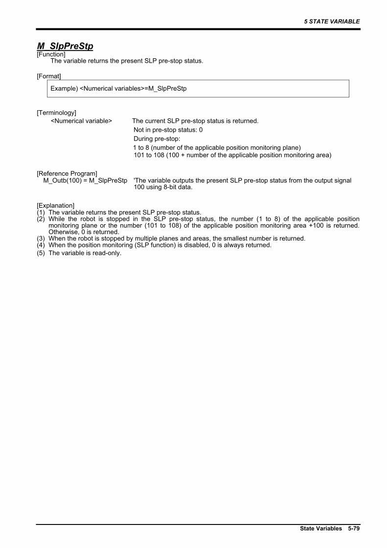
5 STATE VARIABLE
State Variables 5-79
M_SlpPreStp [Function]
The variable returns the present SLP pre-stop status. [Format]
Example) <Numerical variables>=M_SlpPreStp
[Terminology]
<Numerical variable> The current SLP pre-stop status is returned. Not in pre-stop status: 0
During pre-stop: 1 to 8 (number of the applicable position monitoring plane) 101 to 108 (100 + number of the applicable position monitoring area)
[Reference Program] M_Outb(100) = M_SlpPreStp 'The variable outputs the present SLP pre-stop status from the output signal
100 using 8-bit data. [Explanation] (1) The variable returns the present SLP pre-stop status. (2) While the robot is stopped in the SLP pre-stop status, the number (1 to 8) of the applicable position
monitoring plane or the number (101 to 108) of the applicable position monitoring area +100 is returned. Otherwise, 0 is returned.
(3) When the robot is stopped by multiple planes and areas, the smallest number is returned. (4) When the position monitoring (SLP function) is disabled, 0 is always returned. (5) The variable is read-only.

6 TROUBLESHOOTING
6-80 Error List for the Safety Monitoring Functions
6. TROUBLESHOOTING
6.1 Error List for the Safety Monitoring Functions Errors related to the safety monitoring functions are listed below. For details about the errors not listed, refer to "Instruction manual/ Troubleshooting" coming with the robot. (Errors whose error number is suffixed with * requires resetting the power supply.)
Tab. 6-1 Error list for the safety monitoring functions
Error number Error causes and solutions
H0230 *
Error message Safety parameter error (xxxxx) Cause Detect errors in safety parameter value.
Solution There is something wrong with a safety function parameter setting. Check the parameter setting shown in (xxxxx) of the error message, and set it to an appropriate value.
H0231 * Error message Parameter CRC error (xxxxx) Cause Detect CRC errors in safety parameter. Solution Please check the safety parameters settings and write parameters.
C0240
Error message Setting mismatch of safety func Cause The safety function is disabled.
Solution Although the safety logic is configured, the relevant safety functions are disabled. Delete the safety logic or enable the safety functions.
H0241 *
Error message Fault in Safety Communication Cause Detect a fault in safety communication.
Solution
Turn the power OFF and ON once. If the error recurs after that, contact the manufacturer. This error also occurs when the machine lock function and controller CPU drive mode are used. Disable the function/mode, then cycle the power of the robot controller.
H0242 *
Error message Fault in Safety Data Cause Detect a fault in safety data.
Solution Turn the power OFF and ON once. If the error recurs after that, contact the manufacturer.
H0243 Error message Safety function unavailable (XXX) Cause The Safety Function is not supported by this robot. Solution Disable the safety function.
C0244 Error message Setting mismatch of safety IO Cause Safety IO logic is set, but the safety IO is disabled. Solution Delete the safety IO logic settings or enable safety IO.
H0250 * Error message Illegal setting of safety IO I/F Cause Safety IO and Safety comm. are disabled. Solution To enable the safety function, enable either safety IO or safety communications.
H0251 *
Error message Illigal setting of safety IO I/F
Cause Both safety IO and safety communication are set to valid. Safety IO and safety communication cannot be used together.
Solution Disable either safety IO or safety communications.
H0311 *
Error message RemoteI/O unit config error Cause The multiple RemoteI/O units which do not support are connected.
Solution If a safety extension unit is connected, turn off the robot and, after restarting the safety extension unit, turn on the robot again.
H220m (The letter "m" is a number for a
monitoring plane or monitoring area [1 to 8])
Error message SLP (ROBOT position error:CMD Plane) Cause SLP detected the robot position CMD over the monitoring plane. Solution Please confirm the robot movement or related parameter setting. Error message SLP (ROBOT position error:FB Plane) Cause SLP detected the robot position FB over the monitoring plane. Solution Please confirm the robot movement or related parameter setting. Error message SLP (ROBOT position error:CMD Area) Cause SLP detected the robot position CMD over the monitoring area. Solution Please confirm the robot movement or related parameter setting. Error message SLP (ROBOT position error:FB Area) Cause SLP detected the robot position FB over the monitoring area. Solution Please confirm the robot movement or related parameter setting.

6 TROUBLESHOOTING
Error List for the Safety Monitoring Functions 6-81
Error number Error causes and solutions
H222m * (The letter "m" is a DSI number.
[1 to 8])
Error message Mismatch of Dual Safety Input Cause State of the redundant wiring do not match (Dual Safty Input)
Solution
The duplex DSI signal ON/OFF states are not consistent. Check the following for the DSI. • DSI wiring • Duplex signal ON/OFF states • Timing of switching of ON/OFF states (The error occurs when the ON/OFF states of the duplex signals remain inconsistent for about 0.1 seconds.)
H2230 *
Error message Mismatch of Dual Safety Output Cause The duplex DSO states are not consistent.
Solution Turn the power OFF and ON once. If the error recurs after that, contact the manufacturer.
H2231 *
Error message Mismatch of Dual Safety Output Feedback Cause State of Dual Safty Output and the feedback do not match.
Solution Turn the power OFF and ON once. If the error recurs after that, contact the manufacturer.
H2240 *
Error message Origin data change Cause The origin data is changed during execution of the position monitoring function.
Solution The origin is set while position monitoring is being executed. This error occurs if the origin position data is changed while position monitoring is being executed. Cycle the power of the robot controller, then reset the error.
C2250
Error message Safety function execution disabled (No origin setting) Cause The safety function cannot be executed because the origin is not set.
Solution If the origin is not set, the safety monitoring functions will not work. Configure the origin settings.
H2260 *
Error message Safety Unit communication error Cause Extended Safety Unit communication failed
Solution
In order to use the safety monitoring functions, the Safety extension unit must be connected to the robot controller. Connect the Safety extension unit to the robot controller. If the error occurs even when the Safety extension unit is connected, check that the Safety extension unit is powered on. Or check whether pseudo-input mode has been enabled. If none of these solutions rectify the problem, the Safety extension unit may be faulty. Contact Mitsubishi Electric.
H2261 * Error message Extended safety unit's No. error Cause The extended safety unit’s station No. is illegal. Solution Set the extended safety unit’s station No. to 2.
H2270 Error message Cannot servo ON (SS1/STO active) Cause The servo cannot be turned ON while SS1/STO is active. Solution Disable SS1 before turning the servo ON.
H2280 *
Error message SS1 deceleration time exceeded Cause The robot didn't stop within deceleration time from SS1 enabled.
Solution Check operation instructions, terminal load, and stop speed (SFSPZERO) parameter of the robot.
H2281 *
Error message SS2 deceleration time exceeded Cause The robot didn't stop within deceleration time from SS2 enabled.
Solution Check operation instructions, terminal load, and stop speed (SFSPZERO) parameter of the robot.
H2282
Error message SOS (Position error) Cause Detect the change of position FB on SOS.
Solution During the SOS monitoring, change in the position FB due to external force was detected. Remove the external force factor or assess risks and adjust parameter SOSTLRNC to extend the allowable range of the SOS monitoring.
Error message SOS (Speed error) Cause Detect FB speed over on SOS. Solution Please check external force or related parameter settings. Error message SOS (Position command error) Cause Detect the change of position CMD on SOS. Solution Please confirm the robot movement or related parameter setting. Error message SOS (Speed command error) Cause Detect CMD speed over on SOS. Solution Please confirm the robot movement or related parameter setting.
H230n (The letter "n" is an axis number.
[1 to 8])
Error message SLS (Joint Speed Error) Cause Speed monitor detected the speed over.
Solution
The speed monitoring function detected a speed exceeding the predetermined speed. Check the robot movement or the monitoring speed setting. Also, check that the deceleration delay (parameter SLSDLY) is not too short.
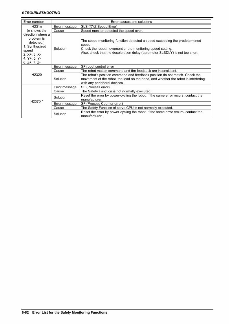
6 TROUBLESHOOTING
6-82 Error List for the Safety Monitoring Functions
Error number Error causes and solutions H231n
(n shows the direction where a
problem is detected.)
1: Synthesized speed 2: X+, 3: X- 4: Y+, 5: Y- 6: Z+, 7: Z-
Error message SLS (XYZ Speed Error) Cause Speed monitor detected the speed over.
Solution
The speed monitoring function detected a speed exceeding the predetermined speed. Check the robot movement or the monitoring speed setting. Also, check that the deceleration delay (parameter SLSDLY) is not too short.
H2320
Error message SF robot control error Cause The robot motion command and the feedback are inconsistent.
Solution The robot's position command and feedback position do not match. Check the movement of the robot, the load on the hand, and whether the robot is interfering with any peripheral devices.
H2370 *
Error message SF (Process error) Cause The Safety Function is not normally executed.
Solution Reset the error by power-cycling the robot. If the same error recurs, contact the manufacturer.
Error message SF (Process Counter error) Cause The Safety Function of servo CPU is not normally executed.
Solution Reset the error by power-cycling the robot. If the same error recurs, contact the manufacturer.
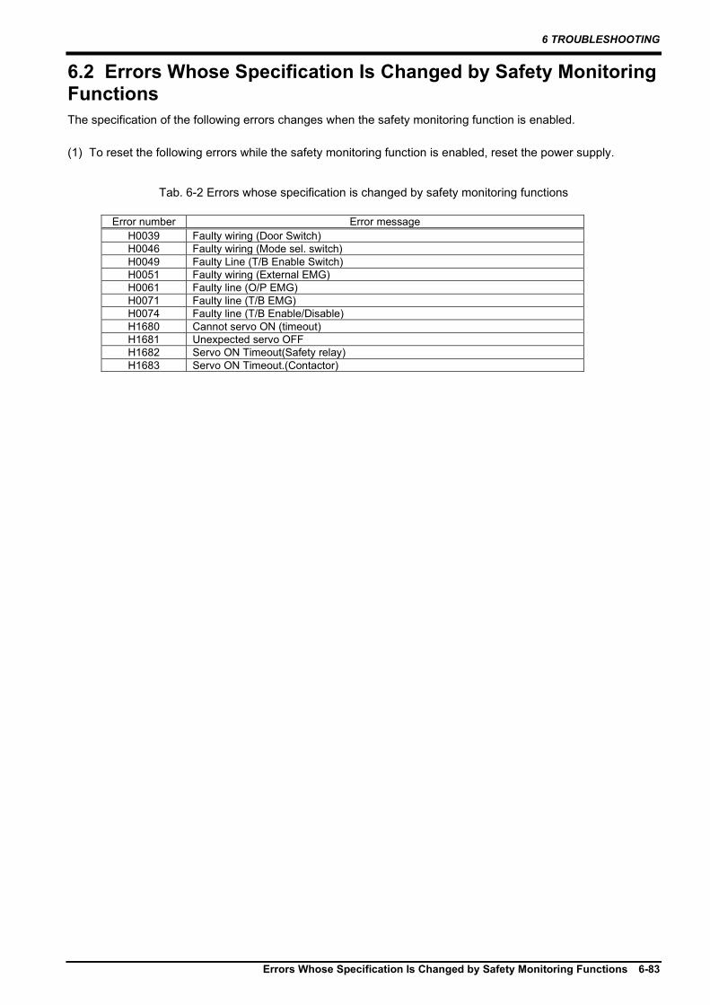
6 TROUBLESHOOTING
Errors Whose Specification Is Changed by Safety Monitoring Functions 6-83
6.2 Errors Whose Specification Is Changed by Safety Monitoring Functions The specification of the following errors changes when the safety monitoring function is enabled. (1) To reset the following errors while the safety monitoring function is enabled, reset the power supply.
Tab. 6-2 Errors whose specification is changed by safety monitoring functions
Error number Error message H0039 Faulty wiring (Door Switch) H0046 Faulty wiring (Mode sel. switch) H0049 Faulty Line (T/B Enable Switch) H0051 Faulty wiring (External EMG) H0061 Faulty line (O/P EMG) H0071 Faulty line (T/B EMG) H0074 Faulty line (T/B Enable/Disable) H1680 Cannot servo ON (timeout) H1681 Unexpected servo OFF H1682 Servo ON Timeout(Safety relay) H1683 Servo ON Timeout.(Contactor)

7 SAFE STOPPING DISTANCE
7-84 How to Calculate a Stopping Distance
7. SAFE STOPPING DISTANCE The concept of the maximum stopping distance of the robot is described below.
7.1 How to Calculate a Stopping Distance Assuming that the power supply to the robot controller is shut off during operation or that an error triggers the SS1 function, the maximum stopping distance in the worst scenario can be approximated by the following formula. (Assume that the robot has brakes on all the axes.)
)5.0()( maxmaxmaxmax α×××+×= TVTVd res
dmax : Maximum stopping distance Vmax : Maximum speed (Equivalent to the SLS monitoring speed when the SLS function is enabled) Tres : Reaction time (time from error detection to stop) (Approximately 7.1 msec) Tmax : Maximum stopping time (Differs from robot to robot, see chapter 7.2 ) α : Safety factor (1 or more)
The stopping time is affected by how the robot system is configured, the condition of the robot, and its posture. Therefore, the stopping distance calculated from this formula is approximate. Use measurements from the system you are using to acquire an accurate stopping distance. Depending on the posture of the robot, the arm may droop if the axis does not have a brake. The amount of droop is not considered in the calculation of the stopping distance described in this section.
position monitoring plane
dmax
position monitoring plane
TCP movement
Safety sphere
Safety sphere
Deceleration start Robot stop
Vmax
<Maximum speed>
When the safely-limited speed function (SLS) is enabled, detection of a speed exceeding the SLS monitoring speed causes the SS1 function to immediately stops the robot. Therefore, the SLS monitoring speed can be considered equivalent to the maximum speed. Thus, reducing the SLS monitoring speed enables shortening the maximum stopping distance when power supply shut-off or an internal error shuts off the driving energy. When Advanced Mode of the SLS function is configured, each of the X, Y, Z components are monitored for their speed, which enables restricting the maximum stopping distances for each of the X, Y, Z components. For example, if there is a safeguarded space in +X direction and the other directions are covered with safety fences, reducing the SLS speed only in +X direction enables ensuring safety and minimizing impact on tact time.
<Reaction time>
The delay between when an error detection enables the SS1 command and when deceleration starts is approximately 7.1 ms. Using the DSI input of the Safety extension unit to stop the robot will have an effect on the DSI filter time specified in the DSI filter settings. For further information, refer to "(c) DSI filter configuration". The initial value is 10 ms, therefore there will be a delay of 10 ms until the DSI input is enabled for the input signal. If an error occurs in the reading of the DSI input, there may be a delay of up to 72 ms before the signal is read.
Caution

7 SAFE STOPPING DISTANCE
Maximum Stopping Time and Maximum Operating Angle 7-85
<Maximum stopping time>
The maximum stopping time differs from robot to robot. (see chapter 7.2 ) (Example) In case of the table on the right, the maximum stopping time is the stopping time of J1 or 0.29 seconds, which results in the maximum stopping time of the robot being 0.29 seconds.
7.2 Maximum Stopping Time and Maximum Operating Angle The maximum stopping time and maximum operating angle indicate the time elapsed from when the SS1 function starts to when the robot stops. With low movement speed, which makes deceleration time short, operation will require a shorter elapsed time and smaller operating angle than those shown here. Improper use of the robot can result in a longer maximum elapsed time and a higher maximum movement speed than the values shown here.
(1) What symbols mean
The following shows meanings of symbols used in this chapter. String Unit Description Description
L mm Degree of arm extension
This is the degree of extension of the arm in relation to each rotation axis. For details, see page 7-86.
M % Load ratio This is the ratio of a load on the robot to the maximum load. Take for an example a robot with a maximum load of 4 kg. If M = 66%, the load on the robot is 2.64 kg.
OVRD % Robot override This is an override for the robot speed. t s
(second) Stopping time This is the maximum duration that elapses from when the SS1
function starts to when the motor power supply is shut off. deg °(degree) Stopping angle This is the maximum angle that the robot moves from when the
SS1 function starts to when the robot stops. d mm Stopping
distance This is the maximum distance that the robot moves from when the SS1 function starts to when the robot stops. This is applicable to the J3 axes of RH-FRH and RH-CRH series robots.
Axis Arm extension Load rate Stopping time [s] Stopping distance [deg]
Ovrd 100% Ovrd 100% J1 L=100% M=100% 0.29 58.80 J2 L=100% M=100% 0.26 42.48 J3 L=100% M=100% 0.24 28.80 J4 - M=100% 0.20 49.80 J5 - M=100% 0.23 61.56 J6 - Load 1 0.14 66.48

7 SAFE STOPPING DISTANCE
7-86 Maximum Stopping Time and Maximum Operating Angle
(2) The degree of extension of the robot arm
(a) RV-FR/RV-CR series
Note) The robot in the figure is RV-4FR.
Axis L=100% L=66% L=33% J1
J2
J3
L=100%
J1 axis J2 axis J3 axis
L=66%
L=33%
J2 axis
J1 axis
L=100%
J3 axis
L=66%
L=33%
L=100%
J3 axis
J2 axis
J1 axis

7 SAFE STOPPING DISTANCE
Maximum Stopping Time and Maximum Operating Angle 7-87
(b) RH-FRH/RH-CRH series
Note) The robot in the figure is RH-6FRH.
Axis L=100% L=66% L=33% J1
J2
L=100%
J1 axis J2 axis
J3 axis
L=66%
L=33%
L=100%
J1 axis
J3 axis J2 axis

7 SAFE STOPPING DISTANCE
7-88 Maximum Stopping Time and Maximum Operating Angle
(3) Load dimension for J6 axis in RV series/J4 axis in RH series
H
W
D
L1
L2
Robot Flange
Axis of rotation
Load(M kg)
Center
Robot model Load type Mass kg Size mm Distance mm
M W D H L1 L2 RV-2FRB Load 1 2 70 70 50 100 45 RV-2FRLB Load 1 2 70 70 50 100 45 RV-4FR Load 1 4 78 78 90 100 95 RV-4FRL Load 1 4 78 78 90 100 95 RV-4FRJL Load 1 4 78 78 90 100 95 RV-7FR Load 1 7 95 95 95 100 170 RV-7FRL Load 1 7 95 95 95 100 170 RV-7FRLL Load 1 7 95 95 95 100 170 RV-13FR Load 1 12 120 120 105 96 124 RV-13FRL Load 1 12 120 120 105 96 124 RV-20FR Load 1 15 160 160 78 73 189 RV-8CRL Load 1 7 95 95 95 100 165 RH-3FRH Load 1 1 72 72 42 71 13
Load 2 3 82 82 61 142 22 RH-6FRH Load 1 3 82 82 61 60 23
Load 2 6 104 104 74 140 29 RH-12FRH Load 1 3 125 80 33 108 19
Load 2 12 165 165 54 158 29 RH-20FRH Load 1 5 125 125 34 133 19
Load 2 20 165 165 91 233 52 RH-3FRHR Load 1 1 180 60 9 50 -5
Load 2 3 82 82 61 77 37 RH-1FRHR Load 1 1 72 72 42 71 13 RH-3CRH Load 1 1 85 85 52 58 12
Load 2 3 115 115 58 131 23 RH-6CRH Load 1 2 93 93 52 54 13
Load 2 6 138 138 45 133 36

7 SAFE STOPPING DISTANCE
Maximum Stopping Time and Maximum Operating Angle 7-89
RV-2FRB Stopping time and stopping distance (emergency stop)
Axis Arm extension Load rate Stopping time [s] Stopping distance [deg] Ovrd 33% Ovrd 66% Ovrd 100% Ovrd 33% Ovrd 66% Ovrd 100%
J1
L=100%
M=100% 0.48 0.60 0.72 25.00 61.75 111.93 M=66% 0.46 0.58 0.70 24.14 60.05 109.35 M=33% 0.43 0.55 0.67 22.49 56.75 104.35 M=0% 0.39 0.51 0.63 20.65 53.07 98.77
L=66%
M=100% 0.38 0.50 0.63 20.23 52.22 97.49 M=66% 0.38 0.49 0.62 19.77 51.31 96.10 M=33% 0.35 0.47 0.59 18.63 49.02 92.63 M=0% 0.33 0.45 0.57 17.35 46.46 88.75
L=33%
M=100% 0.38 0.49 0.62 19.78 51.33 96.13 M=66% 0.36 0.47 0.60 18.78 49.32 93.09 M=33% 0.32 0.44 0.57 17.24 46.24 88.41 M=0% 0.31 0.43 0.55 16.37 44.51 85.80
J2
L=100%
M=100% 0.53 0.65 0.78 13.82 33.52 59.96 M=66% 0.51 0.63 0.75 13.14 32.16 57.91 M=33% 0.48 0.59 0.72 12.38 30.63 55.59 M=0% 0.44 0.56 0.68 11.52 28.93 53.01
L=66%
M=100% 0.44 0.56 0.68 11.44 28.75 52.74 M=66% 0.42 0.54 0.66 10.95 27.79 51.29 M=33% 0.40 0.52 0.64 10.44 26.77 49.74 M=0% 0.37 0.49 0.62 9.87 25.62 48.00
L=33%
M=100% 0.43 0.55 0.67 11.21 28.30 52.06 M=66% 0.40 0.52 0.64 10.46 26.80 49.78 M=33% 0.37 0.49 0.61 9.75 25.37 47.63 M=0% 0.36 0.47 0.60 9.38 24.65 46.52
J3 -
M=100% 0.42 0.54 0.66 22.16 56.09 103.35 M=66% 0.40 0.52 0.64 20.86 53.49 99.40 M=33% 0.37 0.49 0.61 19.37 50.50 94.88 M=0% 0.33 0.45 0.57 17.65 47.05 89.65
J4 -
M=100% 0.39 0.51 0.63 30.81 79.27 147.64 M=66% 0.37 0.49 0.61 29.53 76.71 143.77 M=33% 0.35 0.47 0.60 28.06 73.76 139.29 M=0% 0.33 0.45 0.57 26.43 70.51 134.37
J5 -
M=100% 0.39 0.51 0.63 30.81 79.27 147.64 M=66% 0.37 0.49 0.61 29.53 76.71 143.77 M=33% 0.35 0.47 0.60 28.06 73.76 139.29 M=0% 0.33 0.45 0.57 26.43 70.51 134.37
J6 - Load 1 0.39 0.51 0.63 49.30 126.83 236.23 Stopping time and stopping distance (power off)
Axis Arm extension Load rate Stopping time [s] Stopping distance [deg]
Ovrd 100% Ovrd 100% J1 L=100% M=100% 1.41 108.08
J2 L=100% M=100% 0.38 24.78
J3 L=100% M=100% 0.45 49.42
J4 - M=100% 0.40 100.38
J5 - M=100% 0.38 104.16
J6 - Load 1 0.52 215.32

7 SAFE STOPPING DISTANCE
7-90 Maximum Stopping Time and Maximum Operating Angle
RV-2FRLB Stopping time and stopping distance (emergency stop)
Axis Arm extension Load rate Stopping time [s] Stopping distance [deg] Ovrd 33% Ovrd 66% Ovrd 100% Ovrd 33% Ovrd 66% Ovrd 100%
J1
L=100%
M=100% 0.77 0.85 0.93 27.50 60.48 100.20 M=66% 0.72 0.80 0.88 25.84 57.17 95.20 M=33% 0.67 0.75 0.83 24.16 53.82 90.11 M=0% 0.62 0.70 0.78 22.31 50.12 84.50
L=66%
M=100% 0.60 0.68 0.77 21.78 49.04 82.87 M=66% 0.57 0.65 0.73 20.62 46.73 79.37 M=33% 0.54 0.62 0.70 19.46 44.41 75.85 M=0% 0.50 0.58 0.66 18.17 41.84 71.96
L=33%
M=100% 0.51 0.59 0.67 18.47 42.42 72.84 M=66% 0.47 0.55 0.63 17.24 39.97 69.13 M=33% 0.44 0.52 0.60 15.97 37.43 65.28 M=0% 0.40 0.48 0.56 14.78 35.04 61.66
J2
L=100%
M=100% 0.80 0.88 0.97 14.35 31.45 51.94 M=66% 0.76 0.84 0.93 13.66 30.06 49.82 M=33% 0.72 0.80 0.88 12.92 28.59 47.61 M=0% 0.68 0.76 0.84 12.12 26.99 45.18
L=66%
M=100% 0.64 0.72 0.80 11.50 25.74 43.28 M=66% 0.61 0.69 0.77 11.04 24.83 41.91 M=33% 0.59 0.67 0.75 10.57 23.89 40.48 M=0% 0.56 0.64 0.72 10.06 22.85 38.91
L=33%
M=100% 0.54 0.62 0.70 9.84 22.43 38.26 M=66% 0.52 0.60 0.68 9.36 21.45 36.79 M=33% 0.49 0.56 0.65 8.83 20.40 35.19 M=0% 0.46 0.54 0.62 8.36 19.46 33.76
J3 -
M=100% 0.76 0.84 0.92 21.22 46.96 78.20 M=66% 0.72 0.80 0.89 20.16 44.85 75.00 M=33% 0.68 0.76 0.84 19.05 42.61 71.62 M=0% 0.63 0.71 0.80 17.80 40.13 67.85
J4 -
M=100% 0.53 0.61 0.69 37.83 86.44 147.79 M=66% 0.50 0.58 0.66 35.79 82.37 141.63 M=33% 0.47 0.55 0.63 33.67 78.13 135.20 M=0% 0.44 0.52 0.60 31.37 73.52 128.23
J5 -
M=100% 0.56 0.64 0.72 43.05 97.87 166.65 M=66% 0.50 0.58 0.66 39.05 89.86 154.51 M=33% 0.47 0.55 0.63 36.73 85.23 147.50 M=0% 0.44 0.52 0.60 34.22 80.21 139.88
J6 - Load 1 0.53 0.61 0.69 66.03 150.87 257.97 Stopping time and stopping distance (power off)
Axis Arm extension Load rate Stopping time [s] Stopping distance [deg]
Ovrd 100% Ovrd 100% J1 L=100% M=100% 1.41 108.08
J2 L=100% M=100% 0.38 24.78
J3 L=100% M=100% 0.45 49.42
J4 - M=100% 0.40 100.38
J5 - M=100% 0.38 104.16
J6 - Load 1 0.52 215.32

7 SAFE STOPPING DISTANCE
Maximum Stopping Time and Maximum Operating Angle 7-91
RV-4FR Stopping time and stopping distance (emergency stop)
Axis Arm extension Load rate Stopping time [s] Stopping distance [deg] Ovrd 33% Ovrd 66% Ovrd 100% Ovrd 33% Ovrd 66% Ovrd 100%
J1
L=100%
M=100% 0.48 0.56 0.64 37.27 86.30 149.12 M=66% 0.45 0.53 0.61 35.26 82.29 143.04 M=33% 0.42 0.50 0.58 33.17 78.11 136.70 M=0% 0.39 0.47 0.55 30.91 73.58 129.84
L=66%
M=100% 0.39 0.47 0.55 30.45 72.66 128.46 M=66% 0.37 0.45 0.53 29.12 69.99 124.41 M=33% 0.35 0.43 0.51 27.73 67.23 120.22 M=0% 0.33 0.41 0.49 26.24 64.25 115.71
L=33%
M=100% 0.36 0.44 0.52 28.64 69.04 122.97 M=66% 0.33 0.41 0.49 26.57 64.90 116.70 M=33% 0.30 0.38 0.46 24.30 60.37 109.83 M=0% 0.27 0.35 0.43 22.11 55.99 103.19
J2
L=100%
M=100% 0.46 0.54 0.62 35.57 82.72 143.41 M=66% 0.43 0.51 0.59 33.88 79.50 138.76 M=33% 0.41 0.48 0.57 31.85 75.42 132.58 M=0% 0.38 0.45 0.54 29.63 70.98 125.86
L=66%
M=100% 0.37 0.45 0.53 29.02 69.78 124.03 M=66% 0.35 0.43 0.51 27.74 67.22 120.16 M=33% 0.33 0.41 0.49 26.41 64.56 116.12 M=0% 0.31 0.39 0.47 24.97 61.67 111.75
L=33%
M=100% 0.34 0.42 0.50 27.21 66.16 118.55 M=66% 0.32 0.39 0.48 25.20 62.13 112.45 M=33% 0.29 0.37 0.45 22.99 57.71 105.74 M=0% 0.26 0.34 0.42 20.84 53.42 99.25
J3 -
M=100% 0.43 0.51 0.59 22.34 52.51 91.77 M=66% 0.40 0.48 0.56 21.07 49.97 87.93 M=33% 0.38 0.45 0.54 19.73 47.29 83.87 M=0% 0.35 0.42 0.51 18.26 44.34 79.39
J4 -
M=100% 0.38 0.46 0.54 36.26 86.64 153.30 M=66% 0.36 0.44 0.52 34.31 82.74 147.39 M=33% 0.34 0.42 0.50 32.45 79.02 141.76 M=0% 0.32 0.40 0.48 30.47 75.04 135.74
J5 -
M=100% 0.38 0.46 0.55 41.98 100.25 177.31 M=66% 0.36 0.44 0.52 39.69 95.65 170.35 M=33% 0.34 0.42 0.50 37.44 91.17 163.55 M=0% 0.32 0.40 0.48 35.15 86.58 156.60
J6 - Load 1 0.38 0.46 0.54 48.07 114.95 203.55 Stopping time and stopping distance (power off)
Axis Arm extension Load rate Stopping time [s] Stopping distance [deg]
Ovrd 100% Ovrd 100% J1 L=100% M=100% 0.33 68.60
J2 L=100% M=100% 0.30 49.56
J3 L=100% M=100% 0.27 33.60
J4 - M=100% 0.24 58.10
J5 - M=100% 0.26 71.82
J6 - Load 1 0.17 77.56

7 SAFE STOPPING DISTANCE
7-92 Maximum Stopping Time and Maximum Operating Angle
RV-4FRL Stopping time and stopping distance (emergency stop)
Axis Arm extension Load rate Stopping time [s] Stopping distance [deg] Ovrd 33% Ovrd 66% Ovrd 100% Ovrd 33% Ovrd 66% Ovrd 100%
J1
L=100%
M=100% 0.49 0.57 0.65 35.50 81.98 141.34 M=66% 0.46 0.54 0.62 33.74 78.45 135.99 M=33% 0.44 0.52 0.60 31.91 74.80 130.47 M=0% 0.41 0.49 0.57 29.96 70.89 124.54
L=66%
M=100% 0.39 0.47 0.55 28.87 68.72 121.25 M=66% 0.38 0.45 0.54 27.67 66.32 117.61 M=33% 0.36 0.44 0.52 26.43 63.84 113.85 M=0% 0.34 0.42 0.50 25.11 61.19 109.85
L=33%
M=100% 0.36 0.44 0.52 26.79 64.55 114.93 M=66% 0.34 0.42 0.50 24.97 60.90 109.41 M=33% 0.31 0.39 0.47 23.00 56.97 103.45 M=0% 0.28 0.36 0.44 21.22 53.42 98.07
J2
L=100%
M=100% 0.47 0.55 0.63 27.28 63.30 109.56 M=66% 0.44 0.52 0.60 25.91 60.57 105.42 M=33% 0.42 0.50 0.58 24.50 57.74 101.14 M=0% 0.39 0.47 0.55 22.98 54.69 96.52
L=66%
M=100% 0.37 0.45 0.53 21.99 52.72 93.52 M=66% 0.36 0.44 0.52 21.07 50.88 90.74 M=33% 0.34 0.42 0.50 20.12 48.99 87.87 M=0% 0.32 0.40 0.48 19.10 46.95 84.79
L=33%
M=100% 0.34 0.42 0.50 20.35 49.46 88.62 M=66% 0.32 0.40 0.48 18.93 46.63 84.33 M=33% 0.29 0.37 0.45 17.40 43.57 79.69 M=0% 0.27 0.34 0.43 16.02 40.81 75.51
J3 -
M=100% 0.44 0.51 0.60 18.95 44.44 77.53 M=66% 0.41 0.49 0.57 17.95 42.44 74.51 M=33% 0.39 0.47 0.55 16.92 40.36 71.36 M=0% 0.34 0.42 0.50 14.95 36.44 65.41
J4 -
M=100% 0.40 0.48 0.56 37.77 89.65 157.87 M=66% 0.38 0.46 0.54 35.93 85.97 152.29 M=33% 0.36 0.44 0.52 34.14 82.39 146.87 M=0% 0.34 0.42 0.50 32.30 78.71 141.30
J5 -
M=100% 0.40 0.48 0.56 43.67 103.63 182.43 M=66% 0.38 0.46 0.54 41.49 99.27 175.83 M=33% 0.36 0.44 0.52 39.39 95.06 169.45 M=0% 0.34 0.42 0.50 37.26 90.81 163.01
J6 - Load 1 0.40 0.48 0.56 50.02 118.86 209.47 Stopping time and stopping distance (power off)
Axis Arm extension Load rate Stopping time [s] Stopping distance [deg]
Ovrd 100% Ovrd 100% J1 L=100% M=100% 0.33 68.60
J2 L=100% M=100% 0.30 49.56
J3 L=100% M=100% 0.27 33.60
J4 - M=100% 0.24 58.10 J5 - M=100% 0.26 71.82 J6 - Load 1 0.17 77.56
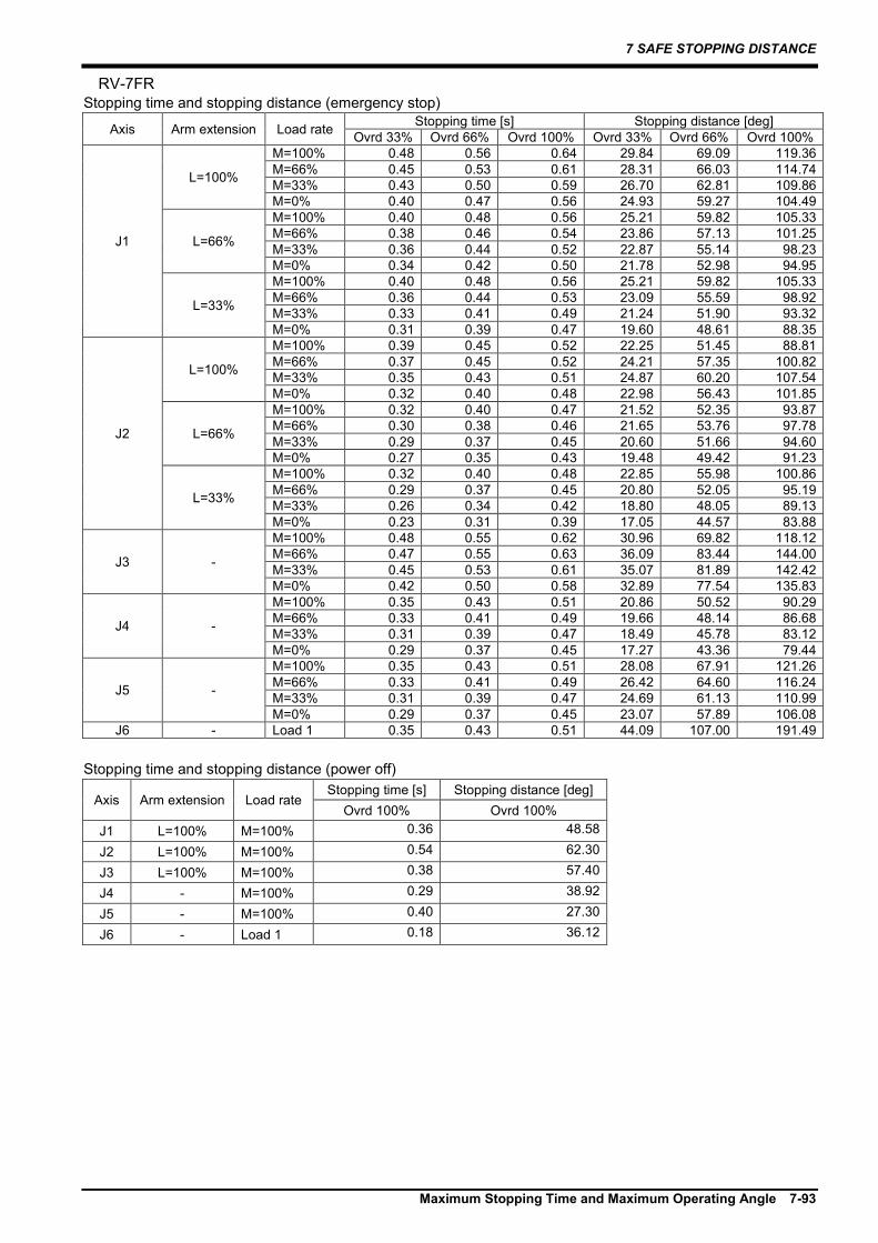
7 SAFE STOPPING DISTANCE
Maximum Stopping Time and Maximum Operating Angle 7-93
RV-7FR Stopping time and stopping distance (emergency stop)
Axis Arm extension Load rate Stopping time [s] Stopping distance [deg] Ovrd 33% Ovrd 66% Ovrd 100% Ovrd 33% Ovrd 66% Ovrd 100%
J1
L=100%
M=100% 0.48 0.56 0.64 29.84 69.09 119.36 M=66% 0.45 0.53 0.61 28.31 66.03 114.74 M=33% 0.43 0.50 0.59 26.70 62.81 109.86 M=0% 0.40 0.47 0.56 24.93 59.27 104.49
L=66%
M=100% 0.40 0.48 0.56 25.21 59.82 105.33 M=66% 0.38 0.46 0.54 23.86 57.13 101.25 M=33% 0.36 0.44 0.52 22.87 55.14 98.23 M=0% 0.34 0.42 0.50 21.78 52.98 94.95
L=33%
M=100% 0.40 0.48 0.56 25.21 59.82 105.33 M=66% 0.36 0.44 0.53 23.09 55.59 98.92 M=33% 0.33 0.41 0.49 21.24 51.90 93.32 M=0% 0.31 0.39 0.47 19.60 48.61 88.35
J2
L=100%
M=100% 0.39 0.45 0.52 22.25 51.45 88.81 M=66% 0.37 0.45 0.52 24.21 57.35 100.82 M=33% 0.35 0.43 0.51 24.87 60.20 107.54 M=0% 0.32 0.40 0.48 22.98 56.43 101.85
L=66%
M=100% 0.32 0.40 0.47 21.52 52.35 93.87 M=66% 0.30 0.38 0.46 21.65 53.76 97.78 M=33% 0.29 0.37 0.45 20.60 51.66 94.60 M=0% 0.27 0.35 0.43 19.48 49.42 91.23
L=33%
M=100% 0.32 0.40 0.48 22.85 55.98 100.86 M=66% 0.29 0.37 0.45 20.80 52.05 95.19 M=33% 0.26 0.34 0.42 18.80 48.05 89.13 M=0% 0.23 0.31 0.39 17.05 44.57 83.88
J3 -
M=100% 0.48 0.55 0.62 30.96 69.82 118.12 M=66% 0.47 0.55 0.63 36.09 83.44 144.00 M=33% 0.45 0.53 0.61 35.07 81.89 142.42 M=0% 0.42 0.50 0.58 32.89 77.54 135.83
J4 -
M=100% 0.35 0.43 0.51 20.86 50.52 90.29 M=66% 0.33 0.41 0.49 19.66 48.14 86.68 M=33% 0.31 0.39 0.47 18.49 45.78 83.12 M=0% 0.29 0.37 0.45 17.27 43.36 79.44
J5 -
M=100% 0.35 0.43 0.51 28.08 67.91 121.26 M=66% 0.33 0.41 0.49 26.42 64.60 116.24 M=33% 0.31 0.39 0.47 24.69 61.13 110.99 M=0% 0.29 0.37 0.45 23.07 57.89 106.08
J6 - Load 1 0.35 0.43 0.51 44.09 107.00 191.49 Stopping time and stopping distance (power off)
Axis Arm extension Load rate Stopping time [s] Stopping distance [deg]
Ovrd 100% Ovrd 100% J1 L=100% M=100% 0.36 48.58
J2 L=100% M=100% 0.54 62.30
J3 L=100% M=100% 0.38 57.40
J4 - M=100% 0.29 38.92
J5 - M=100% 0.40 27.30
J6 - Load 1 0.18 36.12
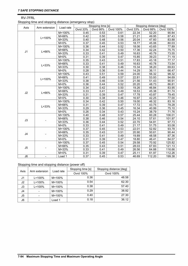
7 SAFE STOPPING DISTANCE
7-94 Maximum Stopping Time and Maximum Operating Angle
RV-7FRL Stopping time and stopping distance (emergency stop)
Axis Arm extension Load rate Stopping time [s] Stopping distance [deg] Ovrd 33% Ovrd 66% Ovrd 100% Ovrd 33% Ovrd 66% Ovrd 100%
J1
L=100%
M=100% 0.45 0.53 0.61 22.34 52.20 90.84 M=66% 0.42 0.50 0.58 21.21 49.95 87.43 M=33% 0.40 0.48 0.56 20.04 47.60 83.88 M=0% 0.37 0.45 0.53 18.77 45.06 80.03
L=66%
M=100% 0.36 0.44 0.52 18.06 43.65 77.89 M=66% 0.34 0.42 0.50 17.36 42.24 75.75 M=33% 0.33 0.41 0.49 16.63 40.79 73.55 M=0% 0.31 0.39 0.47 15.85 39.23 71.19
L=33%
M=100% 0.35 0.43 0.51 17.83 43.18 77.17 M=66% 0.33 0.41 0.49 16.63 40.78 73.54 M=33% 0.30 0.38 0.46 15.34 38.20 69.63 M=0% 0.28 0.36 0.44 14.29 36.11 66.47
J2
L=100%
M=100% 0.43 0.51 0.59 24.00 56.32 98.32 M=66% 0.41 0.49 0.57 22.81 53.93 94.69 M=33% 0.38 0.46 0.54 21.56 51.43 90.91 M=0% 0.36 0.44 0.52 20.20 48.73 86.81
L=66%
M=100% 0.34 0.42 0.50 19.26 46.84 83.95 M=66% 0.33 0.41 0.49 18.53 45.38 81.74 M=33% 0.31 0.39 0.47 17.78 43.87 79.45 M=0% 0.30 0.38 0.46 16.97 42.25 77.00
L=33%
M=100% 0.34 0.42 0.50 19.00 46.32 83.16 M=66% 0.31 0.39 0.47 17.72 43.75 79.28 M=33% 0.29 0.36 0.45 16.34 40.99 75.10 M=0% 0.26 0.34 0.43 15.24 38.79 71.76
J3 -
M=100% 0.40 0.48 0.57 25.44 60.28 106.01 M=66% 0.38 0.46 0.54 24.10 57.61 101.97 M=33% 0.36 0.44 0.52 22.70 54.81 97.73 M=0% 0.33 0.41 0.49 21.17 51.75 93.08
J4 -
M=100% 0.37 0.45 0.53 22.01 52.82 93.78 M=66% 0.35 0.43 0.51 20.90 50.61 90.44 M=33% 0.33 0.41 0.49 19.89 48.58 87.36 M=0% 0.31 0.39 0.47 18.80 46.41 84.07
J5 -
M=100% 0.37 0.45 0.54 29.58 70.92 125.82 M=66% 0.35 0.43 0.51 28.03 67.83 121.13 M=33% 0.33 0.41 0.49 26.56 64.88 116.66 M=0% 0.31 0.39 0.47 25.11 61.97 112.26
J6 - Load 1 0.37 0.45 0.53 46.69 112.20 199.38 Stopping time and stopping distance (power off)
Axis Arm extension Load rate Stopping time [s] Stopping distance [deg]
Ovrd 100% Ovrd 100% J1 L=100% M=100% 0.36 48.58
J2 L=100% M=100% 0.54 62.30
J3 L=100% M=100% 0.38 57.40
J4 - M=100% 0.29 38.92
J5 - M=100% 0.40 27.30
J6 - Load 1 0.18 36.12

7 SAFE STOPPING DISTANCE
Maximum Stopping Time and Maximum Operating Angle 7-95
RV-7FRLL Stopping time and stopping distance (emergency stop)
Axis Arm extension Load rate Stopping time [s] Stopping distance [deg] Ovrd 33% Ovrd 66% Ovrd 100% Ovrd 33% Ovrd 66% Ovrd 100%
J1
L=100%
M=100% 0.63 0.75 0.87 34.66 81.90 143.73 M=66% 0.60 0.72 0.84 33.21 79.01 139.35 M=33% 0.58 0.69 0.82 31.75 76.08 134.91 M=0% 0.55 0.67 0.79 30.21 73.01 130.27
L=66%
M=100% 0.57 0.69 0.81 31.61 75.80 134.50 M=66% 0.54 0.66 0.78 29.85 72.29 129.18 M=33% 0.51 0.62 0.75 28.03 68.64 123.64 M=0% 0.47 0.59 0.71 26.04 64.66 117.62
L=33%
M=100% 0.57 0.69 0.81 31.56 75.71 134.35 M=66% 0.54 0.66 0.78 29.82 72.22 129.07 M=33% 0.50 0.62 0.75 28.00 68.59 123.57 M=0% 0.47 0.59 0.71 26.03 64.65 117.61
J2
L=100%
M=100% 0.57 0.69 0.82 16.18 38.80 68.82 M=66% 0.55 0.67 0.79 15.53 37.48 66.82 M=33% 0.52 0.64 0.77 14.86 36.14 64.79 M=0% 0.50 0.62 0.74 14.15 34.73 62.66
L=66%
M=100% 0.52 0.64 0.76 14.63 35.68 64.10 M=66% 0.49 0.61 0.73 13.81 34.05 61.63 M=33% 0.45 0.57 0.70 12.95 32.34 59.04 M=0% 0.42 0.54 0.66 12.02 30.46 56.19
L=33%
M=100% 0.52 0.63 0.76 14.60 35.63 64.03 M=66% 0.49 0.60 0.73 13.79 34.01 61.57 M=33% 0.45 0.57 0.70 12.94 32.32 59.00 M=0% 0.42 0.54 0.66 12.02 30.46 56.19
J3 -
M=100% 0.57 0.69 0.81 21.33 51.24 91.04 M=66% 0.53 0.65 0.78 20.20 48.98 87.61 M=33% 0.50 0.62 0.74 19.02 46.63 84.05 M=0% 0.47 0.59 0.71 17.75 44.09 80.20
J4 -
M=100% 0.48 0.60 0.73 31.49 77.69 140.66 M=66% 0.47 0.59 0.71 30.65 76.00 138.10 M=33% 0.46 0.58 0.70 29.79 74.29 135.50 M=0% 0.44 0.56 0.68 28.90 72.49 132.79
J5 -
M=100% 0.48 0.60 0.73 37.79 93.22 168.79 M=66% 0.47 0.59 0.71 36.78 91.20 165.72 M=33% 0.46 0.58 0.70 35.75 89.14 162.61 M=0% 0.44 0.56 0.68 34.68 86.99 159.35
J6 - Load 1 0.48 0.60 0.73 60.47 149.16 270.06 Stopping time and stopping distance (power off)
Axis Arm extension Load rate Stopping time [s] Stopping distance [deg]
Ovrd 100% Ovrd 100% J1 L=100% M=100% 0.71 61.34
J2 L=100% M=100% 0.84 39.74
J3 L=100% M=100% 0.85 74.59
J4 - M=100% 0.79 120.24
J5 - M=100% 0.91 135.36
J6 - Load 1 0.18 37.15

7 SAFE STOPPING DISTANCE
7-96 Maximum Stopping Time and Maximum Operating Angle
RV-13FR Stopping time and stopping distance (emergency stop)
Axis Arm extension Load rate Stopping time [s] Stopping distance [deg] Ovrd 33% Ovrd 66% Ovrd 100% Ovrd 33% Ovrd 66% Ovrd 100%
J1
L=100%
M=100% 0.59 0.69 0.80 29.57 68.62 118.76 M=66% 0.56 0.66 0.76 28.07 65.61 114.19 M=33% 0.53 0.63 0.73 26.51 62.49 109.47 M=0% 0.50 0.59 0.70 24.84 59.15 104.42
L=66%
M=100% 0.48 0.58 0.68 24.02 57.52 101.94 M=66% 0.46 0.55 0.66 22.92 55.32 98.61 M=33% 0.43 0.53 0.63 21.79 53.06 95.18 M=0% 0.41 0.51 0.61 20.58 50.64 91.51
L=33%
M=100% 0.42 0.52 0.62 21.16 51.79 93.26 M=66% 0.39 0.49 0.59 19.93 49.33 89.53 M=33% 0.38 0.48 0.58 19.26 47.99 87.50 M=0% 0.37 0.47 0.57 18.71 46.89 85.84
J2
L=100%
M=100% 0.54 0.64 0.74 21.81 51.27 89.62 M=66% 0.51 0.61 0.71 20.70 49.04 86.24 M=33% 0.48 0.58 0.68 19.54 46.73 82.73 M=0% 0.45 0.55 0.65 18.30 44.24 78.96
L=66%
M=100% 0.42 0.52 0.63 17.33 42.31 76.04 M=66% 0.40 0.50 0.61 16.55 40.74 73.67 M=33% 0.38 0.48 0.58 15.74 39.12 71.20 M=0% 0.36 0.46 0.56 14.86 37.37 68.55
L=33%
M=100% 0.37 0.46 0.57 15.02 37.69 69.04 M=66% 0.34 0.44 0.54 14.13 35.91 66.34 M=33% 0.33 0.43 0.53 13.69 35.03 65.01 M=0% 0.32 0.42 0.52 13.35 34.35 63.98
J3 -
M=100% 0.48 0.58 0.68 26.05 62.28 110.28 M=66% 0.46 0.55 0.66 24.71 59.61 106.23 M=33% 0.43 0.53 0.63 23.52 57.24 102.64 M=0% 0.41 0.51 0.61 22.48 55.15 99.47
J4 -
M=100% 0.45 0.55 0.65 29.47 71.20 127.00 M=66% 0.43 0.53 0.63 28.34 68.92 123.55 M=33% 0.41 0.51 0.62 27.16 66.57 119.99 M=0% 0.39 0.49 0.60 25.90 64.05 116.18
J5 -
M=100% 0.45 0.55 0.65 29.47 71.20 127.00 M=66% 0.43 0.53 0.63 28.34 68.92 123.55 M=33% 0.41 0.51 0.62 27.16 66.57 119.99 M=0% 0.39 0.49 0.60 25.90 64.05 116.18
J6 - Load 1 0.45 0.55 0.65 56.59 136.70 243.84 Stopping time and stopping distance (power off)
Axis Arm extension Load rate Stopping time [s] Stopping distance [deg]
Ovrd 100% Ovrd 100% J1 L=100% M=100% 0.69 59.69
J2 L=100% M=100% 0.81 38.66
J3 L=100% M=100% 0.82 72.50
J4 - M=100% 0.77 116.94
J5 - M=100% 0.89 131.61
J6 - Load 1 0.29 106.75

7 SAFE STOPPING DISTANCE
Maximum Stopping Time and Maximum Operating Angle 7-97
RV-13FRL Stopping time and stopping distance (emergency stop)
Axis Arm extension Load rate Stopping time [s] Stopping distance [deg] Ovrd 33% Ovrd 66% Ovrd 100% Ovrd 33% Ovrd 66% Ovrd 100%
J1
L=100%
M=100% 0.56 0.66 0.76 22.49 52.63 91.67 M=66% 0.53 0.63 0.73 21.45 50.55 88.53 M=33% 0.50 0.60 0.71 20.39 48.43 85.32 M=0% 0.48 0.57 0.68 19.27 46.19 81.92
L=66%
M=100% 0.47 0.57 0.67 19.05 45.74 81.23 M=66% 0.45 0.55 0.65 18.44 44.52 79.39 M=33% 0.44 0.54 0.64 17.83 43.31 77.55 M=0% 0.42 0.52 0.62 17.21 42.07 75.68
L=33%
M=100% 0.42 0.52 0.62 17.11 41.87 75.37 M=66% 0.41 0.51 0.61 16.73 41.11 74.22 M=33% 0.40 0.50 0.60 16.36 40.37 73.10 M=0% 0.39 0.49 0.59 15.99 39.62 71.96
J2
L=100%
M=100% 0.57 0.67 0.77 16.16 37.68 65.45 M=66% 0.54 0.64 0.75 15.39 36.13 63.11 M=33% 0.52 0.61 0.72 14.59 34.54 60.70 M=0% 0.48 0.58 0.69 13.75 32.86 58.15
L=66%
M=100% 0.48 0.58 0.68 13.75 32.85 58.13 M=66% 0.47 0.57 0.67 13.27 31.90 56.70 M=33% 0.45 0.55 0.65 12.80 30.95 55.26 M=0% 0.43 0.53 0.63 12.31 29.97 53.78
L=33%
M=100% 0.43 0.53 0.63 12.39 30.14 54.03 M=66% 0.42 0.52 0.62 12.08 29.51 53.08 M=33% 0.41 0.51 0.61 11.77 28.89 52.14 M=0% 0.40 0.50 0.60 11.45 28.25 51.17
J3 -
M=100% 0.49 0.59 0.69 18.48 44.12 78.01 M=66% 0.47 0.57 0.67 17.89 42.94 76.23 M=33% 0.45 0.55 0.66 17.29 41.74 74.41 M=0% 0.44 0.54 0.64 16.66 40.47 72.48
J4 -
M=100% 0.45 0.55 0.65 29.42 71.09 126.83 M=66% 0.44 0.53 0.64 28.41 69.08 123.78 M=33% 0.42 0.52 0.62 27.38 67.02 120.66 M=0% 0.40 0.50 0.60 26.29 64.84 117.37
J5 -
M=100% 0.45 0.55 0.65 29.42 71.09 126.83 M=66% 0.44 0.53 0.64 28.41 69.08 123.78 M=33% 0.42 0.52 0.62 27.38 67.02 120.66 M=0% 0.40 0.50 0.60 26.29 64.84 117.37
J6 - Load 1 0.45 0.55 0.65 56.48 136.49 243.52 Stopping time and stopping distance (power off)
Axis Arm extension Load rate Stopping time [s] Stopping distance [deg]
Ovrd 100% Ovrd 100% J1 L=100% M=100% 0.69 59.69
J2 L=100% M=100% 0.81 38.66
J3 L=100% M=100% 0.82 72.50
J4 - M=100% 0.77 116.94
J5 - M=100% 0.89 131.61
J6 - Load 1 0.29 106.75
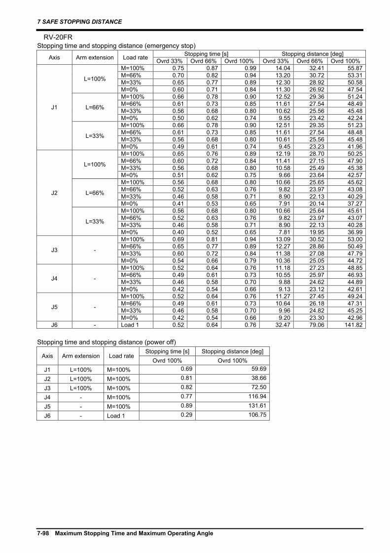
7 SAFE STOPPING DISTANCE
7-98 Maximum Stopping Time and Maximum Operating Angle
RV-20FR Stopping time and stopping distance (emergency stop)
Axis Arm extension Load rate Stopping time [s] Stopping distance [deg] Ovrd 33% Ovrd 66% Ovrd 100% Ovrd 33% Ovrd 66% Ovrd 100%
J1
L=100%
M=100% 0.75 0.87 0.99 14.04 32.41 55.87 M=66% 0.70 0.82 0.94 13.20 30.72 53.31 M=33% 0.65 0.77 0.89 12.30 28.92 50.58 M=0% 0.60 0.71 0.84 11.30 26.92 47.54
L=66%
M=100% 0.66 0.78 0.90 12.52 29.36 51.24 M=66% 0.61 0.73 0.85 11.61 27.54 48.49 M=33% 0.56 0.68 0.80 10.62 25.56 45.48 M=0% 0.50 0.62 0.74 9.55 23.42 42.24
L=33%
M=100% 0.66 0.78 0.90 12.51 29.35 51.23 M=66% 0.61 0.73 0.85 11.61 27.54 48.48 M=33% 0.56 0.68 0.80 10.61 25.56 45.48 M=0% 0.49 0.61 0.74 9.45 23.23 41.96
J2
L=100%
M=100% 0.65 0.76 0.89 12.19 28.70 50.25 M=66% 0.60 0.72 0.84 11.41 27.15 47.90 M=33% 0.56 0.68 0.80 10.58 25.49 45.38 M=0% 0.51 0.62 0.75 9.66 23.64 42.57
L=66%
M=100% 0.56 0.68 0.80 10.66 25.65 45.62 M=66% 0.52 0.63 0.76 9.82 23.97 43.08 M=33% 0.46 0.58 0.71 8.90 22.13 40.29 M=0% 0.41 0.53 0.65 7.91 20.14 37.27
L=33%
M=100% 0.56 0.68 0.80 10.66 25.64 45.61 M=66% 0.52 0.63 0.76 9.82 23.97 43.07 M=33% 0.46 0.58 0.71 8.90 22.13 40.28 M=0% 0.40 0.52 0.65 7.81 19.95 36.99
J3 -
M=100% 0.69 0.81 0.94 13.09 30.52 53.00 M=66% 0.65 0.77 0.89 12.27 28.86 50.49 M=33% 0.60 0.72 0.84 11.38 27.08 47.79 M=0% 0.54 0.66 0.79 10.36 25.05 44.72
J4 -
M=100% 0.52 0.64 0.76 11.18 27.23 48.85 M=66% 0.49 0.61 0.73 10.55 25.97 46.93 M=33% 0.46 0.58 0.70 9.88 24.62 44.89 M=0% 0.42 0.54 0.66 9.13 23.12 42.61
J5 -
M=100% 0.52 0.64 0.76 11.27 27.45 49.24 M=66% 0.49 0.61 0.73 10.64 26.18 47.31 M=33% 0.46 0.58 0.70 9.96 24.82 45.25 M=0% 0.42 0.54 0.66 9.20 23.30 42.96
J6 - Load 1 0.52 0.64 0.76 32.47 79.06 141.82 Stopping time and stopping distance (power off)
Axis Arm extension Load rate Stopping time [s] Stopping distance [deg]
Ovrd 100% Ovrd 100% J1 L=100% M=100% 0.69 59.69
J2 L=100% M=100% 0.81 38.66
J3 L=100% M=100% 0.82 72.50
J4 - M=100% 0.77 116.94
J5 - M=100% 0.89 131.61
J6 - Load 1 0.29 106.75

7 SAFE STOPPING DISTANCE
Maximum Stopping Time and Maximum Operating Angle 7-99
RV-8CRL Stopping time and stopping distance (emergency stop)
Axis Arm extension Load rate Stopping time [s] Stopping distance [deg]
Ovrd 33% Ovrd 66% Ovrd 100% Ovrd 33% Ovrd 66% Ovrd 100%
J1
L=100%
M=100% 0.74 0.80 0.86 36.10 77.85 126.77 M=66% 0.72 0.77 0.84 35.12 75.89 123.81 M=33% 0.66 0.72 0.79 32.72 71.09 116.52 M=0% 0.65 0.77 0.89 33.46 78.68 137.58
L=66%
M=100% 0.58 0.63 0.70 28.47 62.59 103.64 M=66% 0.52 0.58 0.64 25.99 57.63 96.13 M=33% 0.47 0.53 0.59 23.36 52.37 88.15 M=0% 0.41 0.47 0.53 20.46 46.56 79.36
L=33%
M=100% 0.51 0.57 0.63 25.30 56.24 94.02 M=66% 0.46 0.52 0.58 22.91 51.46 86.78 M=33% 0.40 0.46 0.52 20.28 46.21 78.82 M=0% 0.38 0.43 0.50 18.96 43.57 74.83
J2
L=100%
M=100% 0.53 0.59 0.65 29.54 65.37 108.86 M=66% 0.49 0.55 0.61 27.36 61.01 102.26 M=33% 0.45 0.51 0.57 25.05 56.39 95.26 M=0% 0.40 0.46 0.52 22.49 51.27 87.50
L=66%
M=100% 0.44 0.50 0.56 24.38 55.05 93.22 M=66% 0.40 0.46 0.52 22.28 50.86 86.88 M=33% 0.37 0.43 0.49 20.64 47.57 81.89 M=0% 0.33 0.39 0.45 18.86 44.01 76.51
L=33%
M=100% 0.43 0.49 0.55 23.89 54.06 91.74 M=66% 0.38 0.44 0.50 21.59 49.47 84.77 M=33% 0.34 0.39 0.46 19.04 44.38 77.07 M=0% 0.31 0.37 0.44 17.93 42.16 73.70
J3 -
M=100% 0.49 0.55 0.61 30.62 68.29 114.49 M=66% 0.45 0.51 0.57 28.02 63.10 106.61 M=33% 0.40 0.46 0.52 25.21 57.47 98.09 M=0% 0.35 0.41 0.47 21.98 51.01 88.30
J4 -
M=100% 0.57 0.63 0.69 33.03 72.68 120.45 M=66% 0.56 0.62 0.68 32.44 71.51 118.67 M=33% 0.52 0.58 0.64 30.33 67.28 112.27 M=0% 0.47 0.53 0.59 27.67 61.96 104.21
J5 -
M=100% 0.59 0.65 0.71 45.70 100.23 165.63 M=66% 0.58 0.64 0.70 44.60 98.02 162.28 M=33% 0.53 0.59 0.65 41.06 90.94 151.56 M=0% 0.47 0.53 0.59 36.90 82.62 138.94
J6 - Load 1 0.55 0.61 0.67 68.13 150.37 249.87 Stopping time and stopping distance (power off)
Axis Arm extension Load rate Stopping time [s] Stopping distance [deg]
Ovrd 100% Ovrd 100% J1 L=100% M=100% 0.55 80.97
J2 L=100% M=100% 0.37 51.79
J3 L=100% M=100% 0.24 33.57
J4 - M=100% 0.16 25.62
J5 - M=100% 0.13 13.46
J6 - Load 1 0.06 8.48

7 SAFE STOPPING DISTANCE
7-100 Maximum Stopping Time and Maximum Operating Angle
RH-3FRH Stopping time and stopping distance (emergency stop)
Axis Arm extension Load rate Stopping time [s] Stopping distance J1/J2/J4 axis [deg]
J3 axis [mm] Ovrd 33% Ovrd 66% Ovrd 100% Ovrd 33% Ovrd 66% Ovrd 100%
J1
L=100%
M=100% 0.26 0.28 0.31 13.86 30.52 50.61 M=66% 0.24 0.28 0.31 15.82 35.68 60.36 M=33% 0.24 0.28 0.32 18.04 41.58 71.56 M=0% 0.22 0.26 0.30 17.18 39.84 68.93
L=66%
M=100% 0.26 0.28 0.31 13.86 30.52 50.61 M=66% 0.24 0.27 0.31 15.54 35.11 59.50 M=33% 0.22 0.26 0.30 16.90 39.29 68.10 M=0% 0.21 0.25 0.29 16.23 37.94 66.06
L=33%
M=100% 0.26 0.28 0.31 13.86 30.52 50.61 M=66% 0.24 0.27 0.31 15.54 35.11 59.50 M=33% 0.21 0.25 0.29 16.51 38.50 66.90 M=0% 0.21 0.24 0.29 15.88 37.25 65.01
J2 -
M=100% 0.23 0.29 0.35 21.71 53.02 95.32 M=66% 0.23 0.29 0.36 25.36 64.55 119.39 M=33% 0.23 0.30 0.39 29.65 78.12 147.75 M=0% 0.21 0.29 0.37 28.24 75.30 143.47
J3 -
M=100% 0.26 0.34 0.42 51.61 131.39 243.05 M=66% 0.24 0.32 0.40 47.68 124.10 232.91 M=33% 0.22 0.30 0.38 43.89 116.53 221.44 M=0% 0.22 0.30 0.38 44.86 118.48 224.39
J4 - Load 2 0.33 0.35 0.38 52.24 111.53 180.00 Load 1 0.31 0.36 0.42 110.40 255.63 441.69
Stopping time and stopping distance (power off)
Axis Arm extension Load rate Stopping time [s] Stopping distance [deg]
Ovrd 100% Ovrd 100%
J1 L=100% M=100% 0.92 196.55
M=33% 1.28 275.17
J2 L=100% M=100% 1.00 126.12
M=33% 1.40 176.60
J3 - M=100% 0.41 71.82
M=33% 0.34 61.32
J4 - Load 2 2.74 601.95
Load 1 1.45 667.04

7 SAFE STOPPING DISTANCE
Maximum Stopping Time and Maximum Operating Angle 7-101
RH-6FRH Stopping time and stopping distance (emergency stop)
Axis Arm extension Load rate Stopping time [s] Stopping distance J1/J2/J4 axis [deg]
J3 axis [mm] Ovrd 33% Ovrd 66% Ovrd 100% Ovrd 33% Ovrd 66% Ovrd 100%
J1
L=100%
M=100% 0.37 0.45 0.53 17.52 42.29 75.40 M=66% 0.38 0.48 0.59 23.82 60.26 111.01 M=33% 0.38 0.49 0.62 26.38 68.45 128.19 M=0% 0.36 0.48 0.60 25.32 66.31 124.96
L=66%
M=100% 0.34 0.42 0.50 16.37 39.99 71.92 M=66% 0.36 0.46 0.57 22.49 57.60 106.98 M=33% 0.36 0.48 0.60 25.13 65.94 124.40 M=0% 0.34 0.46 0.59 24.32 64.33 121.95
L=33%
M=100% 0.32 0.40 0.49 15.53 38.32 69.38 M=66% 0.34 0.45 0.56 21.56 55.73 104.15 M=33% 0.35 0.46 0.59 24.40 64.48 122.18 M=0% 0.34 0.46 0.58 23.93 63.54 120.75
J2 -
M=100% 0.26 0.33 0.40 21.67 53.48 96.84 M=66% 0.27 0.36 0.45 29.47 76.60 143.62 M=33% 0.27 0.37 0.47 32.38 86.65 165.46 M=0% 0.25 0.35 0.45 30.63 83.15 160.15
J3 -
M=100% 0.25 0.32 0.39 95.89 241.91 444.79 M=66% 0.23 0.31 0.39 96.81 250.11 467.14 M=33% 0.22 0.30 0.38 95.41 253.54 482.08 M=0% 0.23 0.30 0.39 98.83 260.38 492.44
J4 - Load 2 0.33 0.36 0.39 49.79 107.14 174.13 Load 1 0.31 0.37 0.43 104.53 246.80 432.85
Stopping time and stopping distance (power off)
Axis Arm extension Load rate Stopping time [s] Stopping distance [deg]
Ovrd 100% Ovrd 100%
J1 L=100% M=100% 0.53 71.40
M=50% 0.65 95.48
J2 L=100% M=100% 0.43 83.44
M=50% 0.46 119.56
J3 - M=100% 0.09 53.34
M=50% 0.10 145.88
J4 - Load 2 0.94 340.61
Load 1 0.50 377.44

7 SAFE STOPPING DISTANCE
7-102 Maximum Stopping Time and Maximum Operating Angle
RH-12FRH Stopping time and stopping distance (emergency stop)
Axis Arm extension Load rate Stopping time [s] Stopping distance J1/J2/J4 axis [deg]
J3 axis [mm] Ovrd 33% Ovrd 66% Ovrd 100% Ovrd 33% Ovrd 66% Ovrd 100%
J1
L=100%
M=100% 0.48 0.50 0.51 18.28 37.61 58.60 M=66% 0.42 0.44 0.46 22.86 47.82 75.71 M=33% 0.35 0.38 0.40 24.63 52.72 85.28 M=0% 0.32 0.35 0.38 23.82 51.49 84.01
L=66%
M=100% 0.48 0.50 0.51 18.28 37.61 58.60 M=66% 0.42 0.44 0.46 22.86 47.82 75.71 M=33% 0.35 0.37 0.40 24.46 52.37 84.75 M=0% 0.29 0.31 0.34 21.51 46.85 76.99
L=33%
M=100% 0.48 0.50 0.51 18.28 37.61 58.60 M=66% 0.42 0.44 0.46 22.86 47.82 75.71 M=33% 0.35 0.37 0.40 24.46 52.37 84.75 M=0% 0.26 0.29 0.32 19.79 43.42 71.79
J2 -
M=100% 0.47 0.50 0.54 18.94 40.59 65.72 M=66% 0.42 0.47 0.52 24.31 54.06 90.40 M=33% 0.36 0.42 0.49 27.07 63.14 109.73 M=0% 0.34 0.40 0.47 26.72 63.44 111.73
J3 -
M=100% 0.51 0.55 0.59 216.09 466.05 759.02 M=66% 0.43 0.47 0.52 191.96 421.11 696.11 M=33% 0.33 0.37 0.42 156.10 352.91 598.29 M=0% 0.29 0.33 0.38 142.90 329.70 568.10
J4 - Load 2 0.48 0.50 0.51 95.32 195.56 303.97 Load 1 0.38 0.41 0.43 155.60 332.07 535.73
Stopping time and stopping distance (power off)
Axis Arm extension Load rate Stopping time [s] Stopping distance [deg]
Ovrd 100% Ovrd 100%
J1 L=100% M=100% 0.62 24.55
M=25% 0.59 38.17
J2 L=100% M=100% 0.66 57.68
M=25% 1.26 109.27
J3 - M=100% 0.68 269.73
M=25% 0.19 150.08
J4 - Load 2 1.95 281.87
Load 1 0.68 269.73

7 SAFE STOPPING DISTANCE
Maximum Stopping Time and Maximum Operating Angle 7-103
RH-20FRH Stopping time and stopping distance (emergency stop)
Axis Arm extension Load rate Stopping time [s] Stopping distance J1/J2/J4 axis [deg]
J3 axis [mm] Ovrd 33% Ovrd 66% Ovrd 100% Ovrd 33% Ovrd 66% Ovrd 100%
J1
L=100%
M=100% 0.63 0.65 0.68 15.08 31.26 49.08 M=66% 0.55 0.59 0.62 19.30 40.92 65.62 M=33% 0.45 0.50 0.54 20.84 45.62 75.26 M=0% 0.37 0.42 0.47 18.29 40.97 68.94
L=66%
M=100% 0.63 0.65 0.68 15.08 31.26 49.08 M=66% 0.55 0.59 0.62 19.30 40.92 65.62 M=33% 0.45 0.50 0.54 20.84 45.62 75.26 M=0% 0.34 0.38 0.43 16.67 37.73 64.02
L=33%
M=100% 0.63 0.65 0.68 15.08 31.26 49.08 M=66% 0.55 0.59 0.62 19.30 40.92 65.62 M=33% 0.45 0.50 0.54 20.84 45.62 75.26 M=0% 0.31 0.36 0.41 15.46 35.30 60.35
J2 -
M=100% 0.54 0.56 0.59 20.96 43.69 68.96 M=66% 0.47 0.50 0.54 26.53 56.78 91.85 M=33% 0.37 0.42 0.47 27.97 62.26 104.22 M=0% 0.30 0.34 0.39 23.83 54.71 93.92
J3 -
M=100% 0.58 0.62 0.66 202.66 432.13 696.62 M=66% 0.49 0.53 0.58 183.42 397.15 649.07 M=33% 0.38 0.42 0.47 149.09 331.43 554.08 M=0% 0.28 0.33 0.38 121.69 281.01 484.52
J4 - Load 2 0.67 0.67 0.68 29.79 60.21 92.21 Load 1 0.62 0.66 0.69 128.44 270.25 430.32
Stopping time and stopping distance (power off)
Axis Arm extension Load rate Stopping time [s] Stopping distance [deg]
Ovrd 100% Ovrd 100%
J1 L=100% M=100% 0.92 36.82
M=25% 0.88 57.26
J2 L=100% M=100% 1.00 86.52
M=25% 1.89 163.90
J3 - M=100% 1.02 404.60
M=25% 0.21 182.00
J4 - Load 2 2.74 422.80
Load 1 1.02 404.60
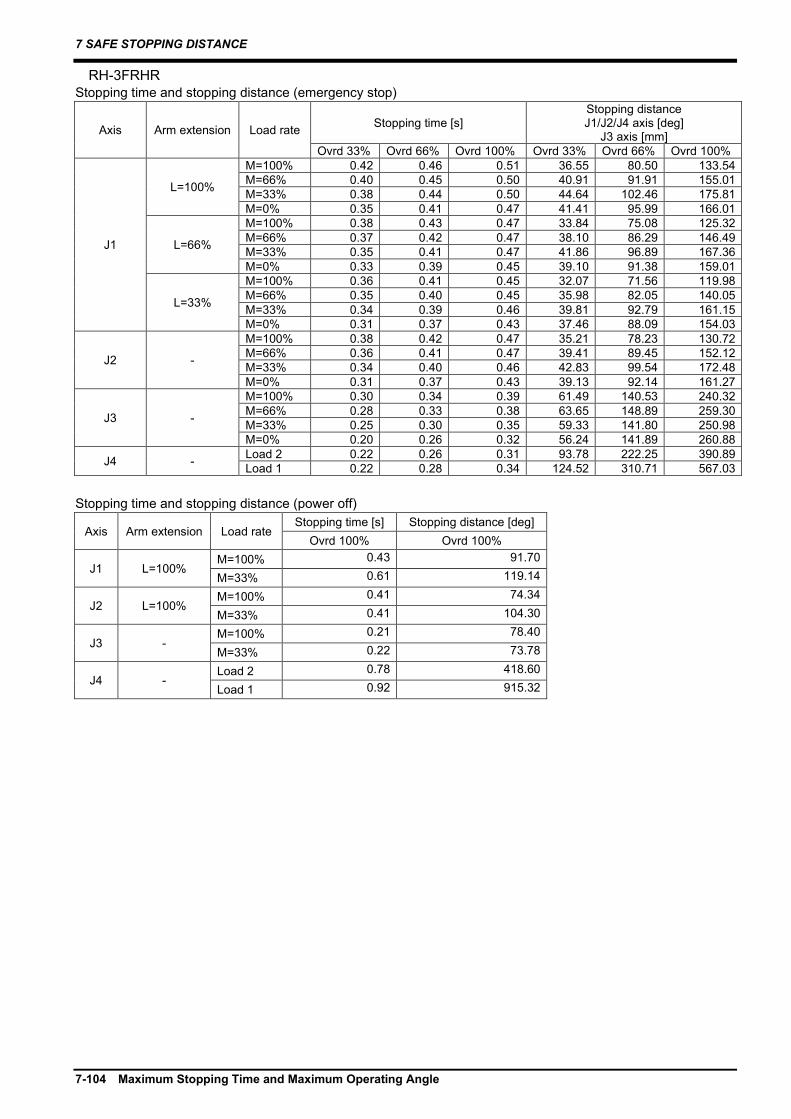
7 SAFE STOPPING DISTANCE
7-104 Maximum Stopping Time and Maximum Operating Angle
RH-3FRHR Stopping time and stopping distance (emergency stop)
Axis Arm extension Load rate Stopping time [s] Stopping distance J1/J2/J4 axis [deg]
J3 axis [mm] Ovrd 33% Ovrd 66% Ovrd 100% Ovrd 33% Ovrd 66% Ovrd 100%
J1
L=100%
M=100% 0.42 0.46 0.51 36.55 80.50 133.54 M=66% 0.40 0.45 0.50 40.91 91.91 155.01 M=33% 0.38 0.44 0.50 44.64 102.46 175.81 M=0% 0.35 0.41 0.47 41.41 95.99 166.01
L=66%
M=100% 0.38 0.43 0.47 33.84 75.08 125.32 M=66% 0.37 0.42 0.47 38.10 86.29 146.49 M=33% 0.35 0.41 0.47 41.86 96.89 167.36 M=0% 0.33 0.39 0.45 39.10 91.38 159.01
L=33%
M=100% 0.36 0.41 0.45 32.07 71.56 119.98 M=66% 0.35 0.40 0.45 35.98 82.05 140.05 M=33% 0.34 0.39 0.46 39.81 92.79 161.15 M=0% 0.31 0.37 0.43 37.46 88.09 154.03
J2 -
M=100% 0.38 0.42 0.47 35.21 78.23 130.72 M=66% 0.36 0.41 0.47 39.41 89.45 152.12 M=33% 0.34 0.40 0.46 42.83 99.54 172.48 M=0% 0.31 0.37 0.43 39.13 92.14 161.27
J3 -
M=100% 0.30 0.34 0.39 61.49 140.53 240.32 M=66% 0.28 0.33 0.38 63.65 148.89 259.30 M=33% 0.25 0.30 0.35 59.33 141.80 250.98 M=0% 0.20 0.26 0.32 56.24 141.89 260.88
J4 - Load 2 0.22 0.26 0.31 93.78 222.25 390.89 Load 1 0.22 0.28 0.34 124.52 310.71 567.03
Stopping time and stopping distance (power off)
Axis Arm extension Load rate Stopping time [s] Stopping distance [deg]
Ovrd 100% Ovrd 100%
J1 L=100% M=100% 0.43 91.70
M=33% 0.61 119.14
J2 L=100% M=100% 0.41 74.34
M=33% 0.41 104.30
J3 - M=100% 0.21 78.40
M=33% 0.22 73.78
J4 - Load 2 0.78 418.60
Load 1 0.92 915.32

7 SAFE STOPPING DISTANCE
Maximum Stopping Time and Maximum Operating Angle 7-105
RH-1FRHR Stopping time and stopping distance (emergency stop)
Axis Arm extension Load rate Stopping time [s] Stopping distance J1/J2/J4 axis [deg]
J3 axis [mm] Ovrd 33% Ovrd 66% Ovrd 100% Ovrd 33% Ovrd 66% Ovrd 100%
J1
L=100%
M=100% 0.22 0.26 0.30 9.76 22.45 38.59 M=66% 0.23 0.27 0.32 11.91 28.02 49.03 M=33% 0.23 0.28 0.33 14.11 33.95 60.39 M=0% 0.23 0.28 0.33 13.91 33.55 59.78
L=66%
M=100% 0.21 0.24 0.28 9.18 21.29 36.82 M=66% 0.21 0.26 0.30 11.24 26.68 47.01 M=33% 0.22 0.27 0.32 13.36 32.46 58.13 M=0% 0.21 0.26 0.32 13.20 32.14 57.64
L=33%
M=100% 0.20 0.24 0.27 8.84 20.61 35.79 M=66% 0.20 0.25 0.29 10.85 25.91 45.84 M=33% 0.21 0.26 0.31 12.94 31.61 56.84 M=0% 0.21 0.26 0.31 12.80 31.33 56.43
J2 -
M=100% 0.24 0.28 0.32 22.23 51.66 89.52 M=66% 0.24 0.29 0.35 27.14 64.65 114.13 M=33% 0.25 0.31 0.37 32.18 78.48 140.94 M=0% 0.24 0.30 0.37 31.91 77.93 140.10
J3 -
M=100% 0.19 0.25 0.31 27.10 69.20 128.25 M=66% 0.19 0.25 0.31 26.69 68.38 127.01 M=33% 0.19 0.25 0.31 26.51 68.02 126.46 M=0% 0.18 0.24 0.31 26.33 67.65 125.91
J4 - Load 1 0.17 0.20 0.24 56.51 134.20 236.38 Stopping time and stopping distance (power off)
Axis Arm extension Load rate Stopping time [s] Stopping distance [deg]
Ovrd 100% Ovrd 100%
J1 L=100% M=100% 0.22 22.12
M=33% 0.35 53.20
J2 L=100% M=100% 0.19 41.02
M=33% 0.26 71.12
J3 - M=100% 0.13 49.28
M=33% 0.11 37.24
J4 - Load 1 0.16 177.24

7 SAFE STOPPING DISTANCE
7-106 Maximum Stopping Time and Maximum Operating Angle
RH-3CRH Stopping time and stopping distance (emergency stop)
Axis Arm extension Load rate Stopping time [s] Stopping distance J1/J2/J4 axis [deg]
J3 axis [mm] Ovrd 33% Ovrd 66% Ovrd 100% Ovrd 33% Ovrd 66% Ovrd 100%
J1
L=100%
M=100% 0.45 0.61 0.78 46.48 125.62 241.34 M=66% 0.46 0.66 0.87 57.88 162.80 320.10 M=33% 0.44 0.63 0.84 54.69 156.43 310.46 M=0% 0.41 0.61 0.81 51.78 150.61 301.64
L=66%
M=100% 0.39 0.55 0.72 40.94 114.55 224.57 M=66% 0.41 0.61 0.82 51.94 150.92 302.11 M=33% 0.39 0.59 0.80 49.54 146.13 294.84 M=0% 0.46 0.66 0.86 57.51 162.07 319.00
L=33%
M=100% 0.35 0.52 0.69 37.18 107.04 213.18 M=66% 0.38 0.58 0.78 47.97 142.98 290.08 M=33% 0.36 0.56 0.77 46.17 139.38 284.62 M=0% 0.44 0.64 0.84 54.81 156.67 310.82
J2 -
M=100% 0.41 0.58 0.75 43.45 119.58 232.18 M=66% 0.43 0.63 0.83 54.25 155.55 309.12 M=33% 0.41 0.61 0.81 51.51 150.07 300.82 M=0% 0.39 0.59 0.79 49.17 145.38 293.71
J3 -
M=100% 0.44 0.64 0.84 85.96 245.11 485.61 M=66% 0.43 0.62 0.83 83.14 239.46 477.05 M=33% 0.41 0.61 0.81 79.92 233.03 467.31 M=0% 0.39 0.59 0.79 76.48 226.14 456.88
J4 - Load 2 0.60 0.67 0.74 95.80 212.86 355.68 Load 1 0.47 0.60 0.74 143.95 364.97 673.29
Stopping time and stopping distance (power off)
Axis Arm extension Load rate Stopping time [s]
Stopping distance J1/J2/J4 axis [deg]
J3 axis [mm] Ovrd 100% Ovrd 100%
J1 L=100% M=100% 0.61 170.70 J2 - M=100% 0.57 174.28 J3 - M=100% 0.27 168.38
J4 - Load 2 0.63 208.89
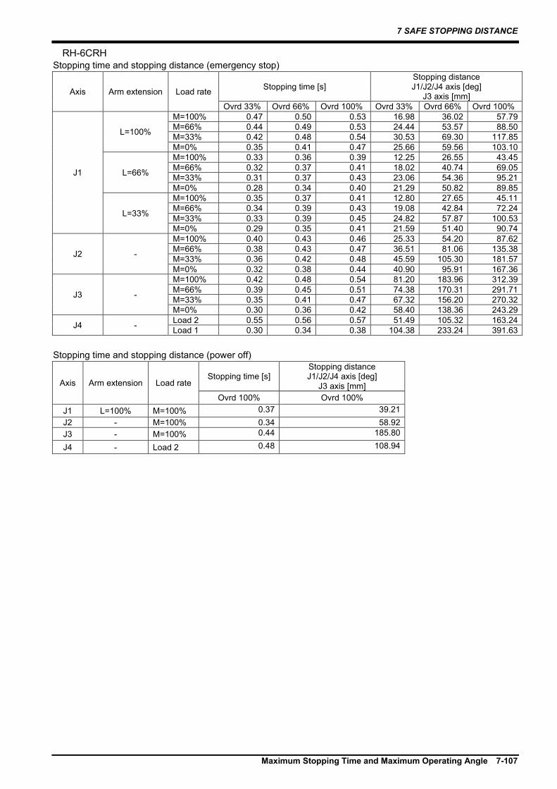
7 SAFE STOPPING DISTANCE
Maximum Stopping Time and Maximum Operating Angle 7-107
RH-6CRH Stopping time and stopping distance (emergency stop)
Axis Arm extension Load rate Stopping time [s] Stopping distance J1/J2/J4 axis [deg]
J3 axis [mm] Ovrd 33% Ovrd 66% Ovrd 100% Ovrd 33% Ovrd 66% Ovrd 100%
J1
L=100%
M=100% 0.47 0.50 0.53 16.98 36.02 57.79 M=66% 0.44 0.49 0.53 24.44 53.57 88.50 M=33% 0.42 0.48 0.54 30.53 69.30 117.85 M=0% 0.35 0.41 0.47 25.66 59.56 103.10
L=66%
M=100% 0.33 0.36 0.39 12.25 26.55 43.45 M=66% 0.32 0.37 0.41 18.02 40.74 69.05 M=33% 0.31 0.37 0.43 23.06 54.36 95.21 M=0% 0.28 0.34 0.40 21.29 50.82 89.85
L=33%
M=100% 0.35 0.37 0.41 12.80 27.65 45.11 M=66% 0.34 0.39 0.43 19.08 42.84 72.24 M=33% 0.33 0.39 0.45 24.82 57.87 100.53 M=0% 0.29 0.35 0.41 21.59 51.40 90.74
J2 -
M=100% 0.40 0.43 0.46 25.33 54.20 87.62 M=66% 0.38 0.43 0.47 36.51 81.06 135.38 M=33% 0.36 0.42 0.48 45.59 105.30 181.57 M=0% 0.32 0.38 0.44 40.90 95.91 167.36
J3 -
M=100% 0.42 0.48 0.54 81.20 183.96 312.39 M=66% 0.39 0.45 0.51 74.38 170.31 291.71 M=33% 0.35 0.41 0.47 67.32 156.20 270.32 M=0% 0.30 0.36 0.42 58.40 138.36 243.29
J4 - Load 2 0.55 0.56 0.57 51.49 105.32 163.24 Load 1 0.30 0.34 0.38 104.38 233.24 391.63
Stopping time and stopping distance (power off)
Axis Arm extension Load rate Stopping time [s]
Stopping distance J1/J2/J4 axis [deg]
J3 axis [mm] Ovrd 100% Ovrd 100%
J1 L=100% M=100% 0.37 39.21 J2 - M=100% 0.34 58.92 J3 - M=100% 0.44 185.80
J4 - Load 2 0.48 108.94

7 SAFE STOPPING DISTANCE
7-108 Calculating stopping distance and stopping time
7.3 Calculating stopping distance and stopping time This section explains how to calculate stopping distance and stopping time with RT ToolBox3. Calculating the stopping distance and time based on actual peripheral devices (such as hands) and the program that will be used will provide more accurate results. For information on how to use RT ToolBox3 or how to configure the advanced settings, refer to the RT ToolBox3 or RT ToolBox3 mini Instruction Manual.
① Configure the log settings of the oscillograph function. Connect the robot controller to RT ToolBox3 via Ethernet, set the controller to Online mode, then select Tool → Oscillograph. Configure the communication settings as follows: ・Method: Real time monitor ・Data No.1 to 4: Robot Information / XYZ position (FB) / Joint position (FB) / State of DSI Input
Note that Real time monitor cannot be selected when the robot controller is connected to RT ToolBox3 via USB. If some of the data that has been received is lost, we recommend connecting the robot controller and computer directly (not via a network hub), using a high-performance computer, or not using this software while any other application is open.
② Create the robot log. Open [Log Setting] from the menu bar, then check the Log the Measurement Data check box. Select [Real time monitor] in the [Select the Interval to Log] drop down box, then choose a folder to save the log file in. Select [Start Record] to start logging data. Select [Stop Record] to stop logging data.

7 SAFE STOPPING DISTANCE
Calculating stopping distance and stopping time 7-109
③ Log data. Operate the robot and start data logging. Next, input the stop signal. Finish data logging after the robot has stopped. A simple way to input the stop signal, is to input it from the emergency stop switch (EMS Switch) connected to the emergency stop input of the robot controller. If a teaching pendant is connected, the emergency stop switch on the teaching pendant can also be used. The robot can also be stopped by connecting a signal, which acts as a trigger, to the DSI input of the Safety extension unit. When using this method, SS1 must be assigned to the relevant DSI input in the safety input settings under Safety logic in RT ToolBox3.
Using the DSI input of the Safety extension unit to stop the robot will have an effect on the DSI filter time specified in the DSI filter settings. For further information, refer to "(c) DSI filter configuration". The initial value is 10 ms, therefore there will be a delay of 10 ms until the DSI input is enabled for the input signal.
Caution

7 SAFE STOPPING DISTANCE
7-110 Calculating stopping distance and stopping time
④ Interpret the stopping distance and stopping time. The logged data will be saved as a file in the folder you have specified. The current date and time will be used as the file name (e.g. "LOGYYYYMMDD-hhmmss.csv"). The first three rows in the CSV file contain information such as column titles and units of measurement. Data sampled at intervals is contained in the rows from the fourth row onwards. Check the values in the Output column. This number has been changed from a 32-bit binary value (assigned to the general-purpose output signal) to a decimal value. If the output signal of "ERRRESET" is set to "2", the value will increase to four (22 = 4) when an error occurs. When the emergency stop signal is input, the robot will enter an error state. By checking the time when bit 2 changes to "4" in the output column, you can see when the stop signal was input. The CSV file can be used to check the time that the robot stopped. The "Tool point speed (FB)" column in the file shows the speed of the tool control point. Look for where the speed decreases to zero after the stop signal has been input. The stopping time is the time from when the stop signal is input to when the speed becomes zero. By checking the XYZ position (FB) data or Joint position (FB) data at the times when the stop signal was input and at the time the robot stopped, it is possible to find the stopping distance of the tool center point within the XYZ coordinate system and the stopping distance (angle) of individual axes. Refer to the graphs on the following page which show an example of the stopping distance of the J1 axis. If there is a delay when the stop signal is input, consider the time that the signal was output as earlier than what is shown in the graph.
Stopping time
Stopping distance
If the device used to input the stop signalhas a delay, add the time of the delay ontothe stopping time.

8 APPENDIX
Appendix 1: EMC installation guideline 8-111
8. APPENDIX
8.1 Appendix 1: EMC installation guideline 8.1.1 Outlines The EMC directive is coerced from January 1, 1996, and it is necessary to attach the CE mark which shows that the product is in conformity to directive. Since the industrial robot is the component of the automation system, it considers that the EMC directive is not the target product of the direct. However, because it is one of the main components, introduces the method and components of the measures for conforming the automation system to the EMC directive. And also we are carrying out the qualification test about the conformity of the EMC directive under the environment based on the contents of this document. However, the noise level is changed by the kind of equipment to be used, the layout, the construction of the controlling board, the course of wiring, etc. Therefore, please confirm by the customer eventually.
8.1.2 EMC directive The Mitsubishi Electric industrial robot follows the European EMC directive. EMC can be broadly classified into two categories: EMI and EMS. (1) Emission (EMI: Electromagnetic Interference) .......The capacity not to generate the disturbance noise which
has a bad influence outside. (2) Immunity (EMS: Electromagnetic Susceptibility) ...The capacity which does not malfunction for the
disturbance noise from the outside. Each contents are shown below. Item Name Contents Emission (EMI)
Radiative noise disturbance The electromagnetic noise etc. which are emitted to environs.
Electrical-conduction noise disturbance The electromagnetism noise etc. which flow out of the power-supply line.
Immunity (EMS)
Electrostatic discharge immunity test The noise from the electrified human body. Radiated, radio-frequency, electromagnetic field immunity test susceptibility test
The electromagnetism noise from the transceiver, the broadcasting station, etc.
Electrical fast transient burst immunity test The relay noise or the electromagnetism noise etc. which are caused in power-supply ON/OFF.
Immunity to conducted distrurbances induced radio-frequency fields
The electromagnetism noise etc. which flow in through the power source wire and the grounding wire.
Power frequency magnetic field immunity test
The electromagnetism noise with a power supply frequency of 50/60 Hz etc.
Voltage dips, short interruptions and voltage variations immunity test
The noise in the variation of the source voltage of the power dispatching, etc.
Surge immunity test The electromagnetism noise by the thunderbolt, etc.
8.1.3 EMC measures There are mainly following items in the EMC measures. (1) Store into the sealed metal board. (2) Grounding all the conductor that have floated electrically (makes the impedance low). (3) Wiring so that the power source wire and signal wire are separated. (4) Use the shield cable for the cable which wired outside of the metal board. (5) Install the noise filter.

8 APPENDIX
8-112 Appendix 1: EMC installation guideline
To suppress the noise emitted out of the board, be careful of the following item. (1) Ensure grounding of the equipment. (2) Use the shield cable. (3) Separate the metal board electrically. Narrows the distance/hole. The strength of electromagnetic noise emitted to environment is changed a lot by the shielding efficiency of cable and the distance of metal board, so it should be careful.
8.1.4 Component parts for EMC measures (1) Ferrite core The ferrite core is mounted by the plastics case as one. It can attach by the one-touch, without cutting the cable. This has the effect in the common-mode noise. The measures against the noise are made not influential in the quality of the signal. Manufacturer: SEIWA ELECTRIC MFG. CO., Ltd Type Outside dimension (mm) Applicable cable
Diameter [max] (mm)
A B C D E
E04SR170730A 30.0 23.0 7.0 16.5 15.0 φ4.0-7.0 Example of installation)
(2) Line noise filter Install a line noise filter to AC input line. Type: SUP-EL20-ER-6 Manufacturer: OKAYA ELECTRIC INDUSTRIES CO., LTD.
Robot controller
Ferrite core
RIO Cable
Control panel
Safety extension unit
100±2.0Terminal cover (transparent)
6-M4
53.1±1.0
10.0
(11.6)(13.0)
12.0
50.0
60.0
88.075.0
2.0
2-φ4.5×6.75
Unit: mmTolerances: ±0.5
2-φ4.5
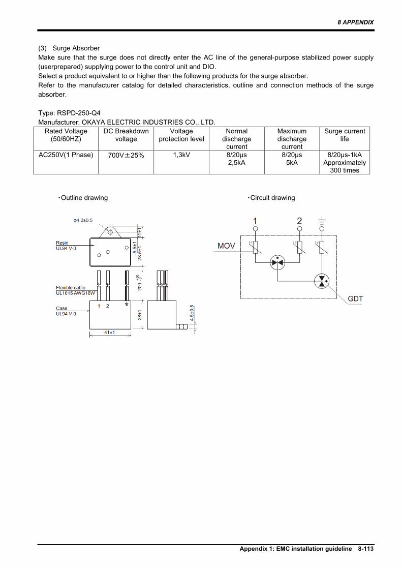
8 APPENDIX
Appendix 1: EMC installation guideline 8-113
(3) Surge Absorber Make sure that the surge does not directly enter the AC line of the general-purpose stabilized power supply (userprepared) supplying power to the control unit and DIO. Select a product equivalent to or higher than the following products for the surge absorber. Refer to the manufacturer catalog for detailed characteristics, outline and connection methods of the surge absorber. Type: RSPD-250-Q4 Manufacturer: OKAYA ELECTRIC INDUSTRIES CO., LTD.
Rated Voltage (50/60HZ)
DC Breakdown voltage
Voltage protection level
Normal discharge
current
Maximum discharge
current
Surge current life
AC250V(1 Phase) 700V±25% 1,3kV 8/20μs 2,5kA
8/20μs 5kA
8/20μs-1kA Approximately
300 times
・Outline drawing ・Circuit drawing


Apr. 2021 MEE Printed in Japan on recycled paper. Specifications are subject to change without notice.