Embed Size (px)
Citation preview

CRANIO FACIAL Reconstruction
EXPANDING PROVEN CONCEPTS
CAT-2036-02 (C344)
Design & Layout by Ruan Pienaar
Dear Customers and Colleagues
Graham BlackbeardManaging DirectorSouthern Implants
Today, Dental Implants have become an indispensable part of Dental treatment options. With the globalization of medical infrastructures and higher standards of living, implant applications have rapidly become common.
Southern Implants has been a manufacturer and distributor of Dental Implants since 1987. Today, the Southern group is recognized as a leading bio-medical engineering entity, with major intellectual property and capabilities in implantable devices, arthroplasties, tissue regeneration, stem cells and cryoscience. The top-end professional users, who want more choices, have driven the product range expansion to enormous and exciting heights. Striving for excellence and meeting customer needs has lead to our wide product range characterized by numerous unique and innovative products which include:
- 3 interfaces: External hex, Internal morse taper/octagon, and Tri-nex.- Many products optimized for primary stability and suited for immediate loading.- The only angled-top tapered screw-form 12° and 24° Co-Axis implant.- Implant lengths from 6mm to 20mm and diameters from 2.90mm to 10mm.- A surface which continues to out-perform that which it is trialed against.- Color-coded components for easy part recognition.- 55° Zygomatic implant, optimized for load distribution.- Compatibility with major brands, giving the patient more options.- The MAX, wide diameter implant for molar teeth replacement.
Striving for excellence is synonymous with the search to improve. At Southern the development starts with computer simulation and Finite Element Modeling. This is followed by extensive laboratory trials and testing. Finally, clinical research has taken on a new dimension in our overall strategy where our preference is for independent RCTs.
Our sincere thanks to all specialists, dentists and technicians who give continual feedback, suggestions and input. The products here are our interpretation of your needs.
Yours sincerely
Southern Implants was established in 1987 as a manufacturer and distributor of dental implants. At this time the science on a worldwide basis was still in it's infancy. Southern implants has been a pioneer in this field for the last 21 years and has contributed extensively to enhancements with respects to the osseointegration of implant devices, surgical techniques, patient education and options of treatment.
The company is focused on the top-end specialist sector of the implant market. The product range is constantly being expanded to incorporate the newest technologies and trends. Where many of our competitors are rationalizing their product range, Southern is offering more choices.
The implants are made from ASTM-F67-95 Grade 4 pure titanium, with a tensile strength of 550 MPa. The surface is enhanced with abrasion and chemical conditioning. The surface has been proven by way of extensive animal and clinical trials and has been in use for more than 15 years.
Southern Implants is not only the leading implant company in Southern Africa, but is a significant role player in the USA, the UK, Europe and Australasia. Manufacturing plants are situated in Irene, South Africa and Irvine, California. Each Plant produces 60 000 implants per annum.
Why Southern Implants?

www.southernimplants.com
Introduction and Welcoming Letter
IE Implant - Instruction for Use
List of Figures
IE Implants & components
Prosthetic Options - IE Implant
Ball Abutment for use with IE Implant - OBE
Transcutaneous Standard Abutment - ABE
Southern Implants’ Enhanced Surface
Publication“Sinus Reactions to Immediate Loaded Zygoma Implants: A Clinical and Radiological Study”Preferred Positioning of Zygomatic Implants
Zygomatic & Oncology Implants
Operative Procedures
Postoperative ManagementSecond Stage SurgeryNon-integration of Implant.
Zygomatic Implants & components
Prosthetic Options - Zygomatic Implant
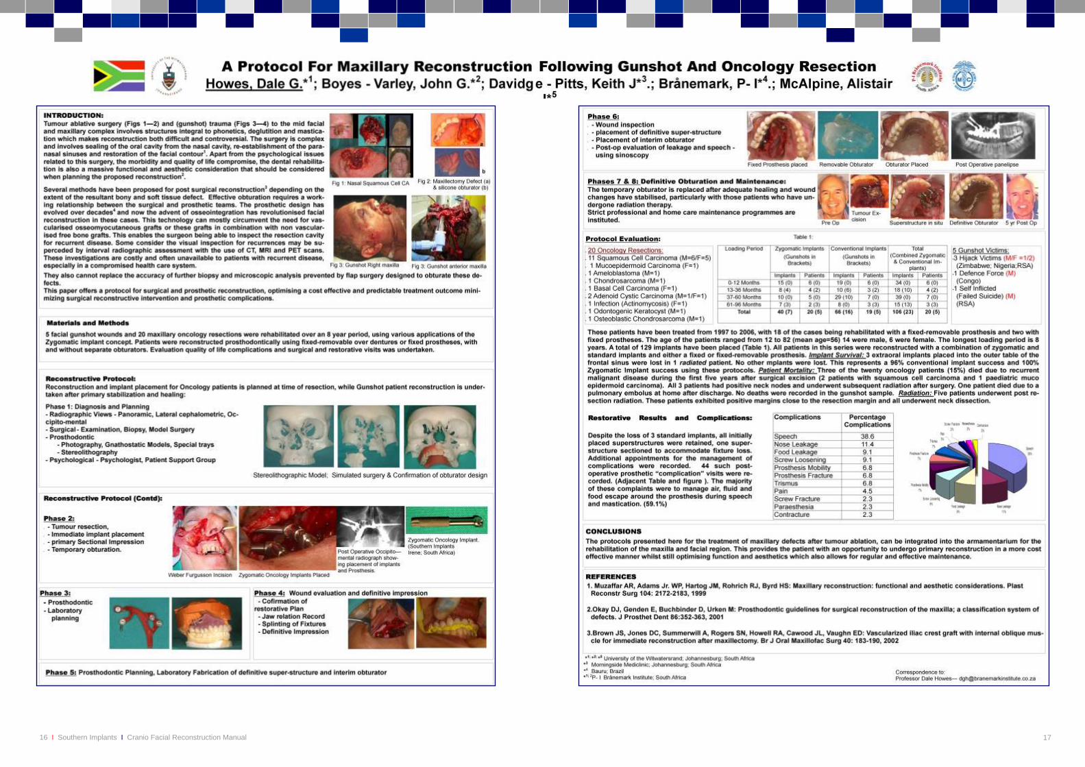
Poster Presentation“A Protocol for Maxillary Reconstruction Following Gunshot and Oncology Resection”
I-ZYG Zygomatic TrayZygomatic Instruments
CertificatesComplimentary Manuals & InstructionsLabeling Symbols
Contact Details (Local and International)
.................................................................................................................
............................................................................................................................................................
......................................................................................................................................................................................
..................................................................................................................................................................
...........................................................................................................................................................
.......................................................................................................................................
.........................................................................................................................................
................................................................................................................................................
......................................................................................................................................
.........................................................................................................................................................
.........................................................................................................................................................................
..................................................................................................................................................................
.....................................................................................................................................................
..............................................................................................................................................
.....................................................................
........................................................................................................................................................................
................................................................................................................................................................................
............................................................................................................................................
.....................................Inside Front Cover
Page 02
Page 03
Page 04
Page 05
Page 06
Page 07
Page 08
Page 09
Page 11
Page 12
Page 13
Page 14
Page 15
Page 16-17
Page 20
InsideBack Cover
Back Cover
Content
02 Southern Implants Cranio Facial Reconstruction ManualI I
Instructions for Use
Extra Oral implants have a number of different indications for use, such as retaining cranio facial prosthesis’ and bone conductor hearing aids. The general placement procedure is similar in most extra oral cases and therefore an example for an auricular prosthesis will be used.
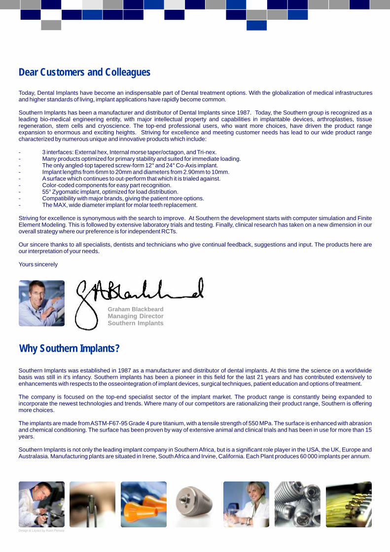
The availability of bone as well as ideal placement for attachment of the prosthesis are considerations that need to be taken into account when dealing with extra oral implants. Case planning with the prosthesists making use of CT scans or other case planning devices, is highly recommended. At this stage the length of implant would be determined from the availability of bone.
Prepare the implant site by removing any remaining tissue or ligatures from the area. Make appropriate incisions and pull back the skin - exposing the implant site. The reduction of skin thickness is important to avoiding subsequent soft-tissue problems. Multiple authors have advocated subcutaneous skin reduction, fixed non-mobile skin and absence of hair sometimes requiring grafting of non hair-bearing skin to periosteum. The reduction of skin can take place at implant placement or abutment connection. This excision of a portion of dermal and subcutaneous tissue often includes removal of the adnexal structures, muscle, blood vessels and nerves. This is to aid in fixing the skin to the periosteum, to minimize mobility and remove glandular components.
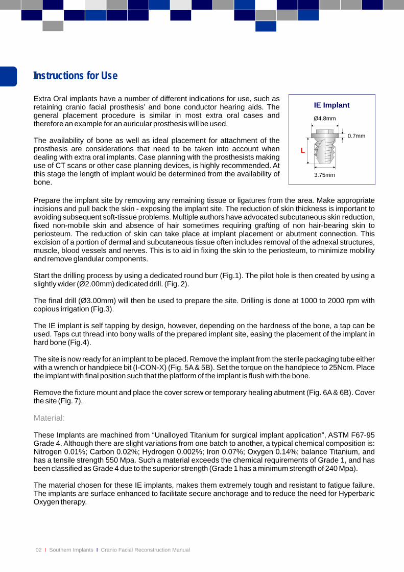
Start the drilling process by using a dedicated round burr (Fig.1). The pilot hole is then created by using a slightly wider (Ø2.00mm) dedicated drill. (Fig. 2).
The final drill (Ø3.00mm) will then be used to prepare the site. Drilling is done at 1000 to 2000 rpm with copious irrigation (Fig.3).
The IE implant is self tapping by design, however, depending on the hardness of the bone, a tap can be used. Taps cut thread into bony walls of the prepared implant site, easing the placement of the implant in hard bone (Fig.4).
The site is now ready for an implant to be placed. Remove the implant from the sterile packaging tube either with a wrench or handpiece bit (I-CON-X) (Fig. 5A & 5B). Set the torque on the handpiece to 25Ncm. Place the implant with final position such that the platform of the implant is flush with the bone.
Remove the fixture mount and place the cover screw or temporary healing abutment (Fig. 6A & 6B). Cover the site (Fig. 7).
These Implants are machined from “Unalloyed Titanium for surgical implant application”, ASTM F67-95 Grade 4. Although there are slight variations from one batch to another, a typical chemical composition is: Nitrogen 0.01%; Carbon 0.02%; Hydrogen 0.002%; Iron 0.07%; Oxygen 0.14%; balance Titanium, and has a tensile strength 550 Mpa. Such a material exceeds the chemical requirements of Grade 1, and has been classified as Grade 4 due to the superior strength (Grade 1 has a minimum strength of 240 Mpa).
The material chosen for these IE implants, makes them extremely tough and resistant to fatigue failure. The implants are surface enhanced to facilitate secure anchorage and to reduce the need for Hyperbaric Oxygen therapy.
Material:
IE Implant
L
Ø4.8mm
3.75mm
0.7mm
03
Placement Technique
figure 1 figure 2 figure 3
figure 4 figure 5A figure 5B
figure 6B figure 7figure 6A
04 Southern Implants Cranio Facial Reconstruction ManualI I
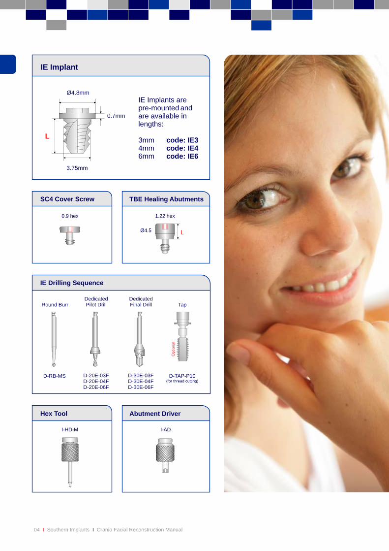
LØ4.5
0.9 hex 1.22 hex
TBE Healing AbutmentsSC4 Cover Screw
IE Implant
IE Drilling Sequence
D-RB-MS
Round BurrDedicatedPilot Drill
Abutment DriverHex Tool
DedicatedFinal Drill Tap
D-20E-03FD-20E-04FD-20E-06F
D-30E-03FD-30E-04FD-30E-06F
D-TAP-P10(for thread cutting)
L
Ø4.8mm
3.75mm
0.7mm
IE Implants arepre-mounted andare available inlengths:
3mm code: IE34mm code: IE46mm code: IE6
I-ADI-HD-M
05
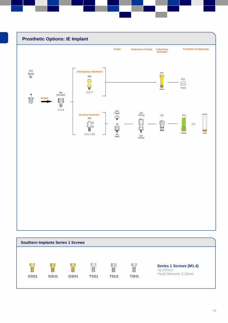
Prosthetic Options: IE Implant
Southern Implants Series 1 Screws
OBE
Overdenture Abutment
IE4 / 5 / 7
GSS1 TSS1 TSH1 GSU1 GSH1 TSU1
Series 1 Screws (M1.4)10-15NcmHead Diameter 2.25mm
TBE(one-part)
SC4
Direct
Standard Abutment
4 / 5 / 7 / 8.5
3 / 4 / 6
ABE
HB
4/6Metal
HB3Plastic
CB1Pick-up
CB2Transfer
LS1
AO2
Brass
PC5
Plastic
PC2
Plastic
OR
Gold
GCP3
Temps Impression Coping Laboratory Analogue
Prosthetic Components
06 Southern Implants Cranio Facial Reconstruction ManualI I
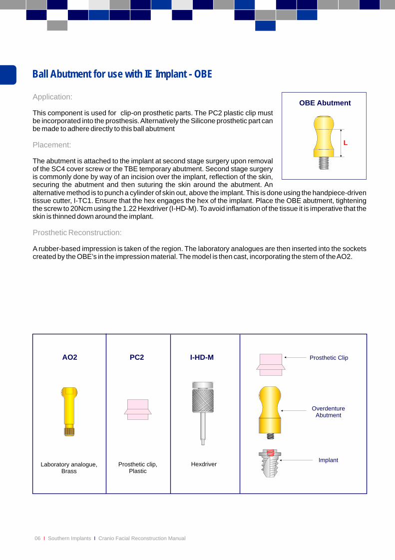
Ball Abutment for use with IE Implant - OBE
Application:
Placement:
This component is used for clip-on prosthetic parts. The PC2 plastic clip must be incorporated into the prosthesis. Alternatively the Silicone prosthetic part can be made to adhere directly to this ball abutment
The abutment is attached to the implant at second stage surgery upon removal of the SC4 cover screw or the TBE temporary abutment. Second stage surgery is commonly done by way of an incision over the implant, reflection of the skin, securing the abutment and then suturing the skin around the abutment. An alternative method is to punch a cylinder of skin out, above the implant. This is done using the handpiece-driven tissue cutter, I-TC1. Ensure that the hex engages the hex of the implant. Place the OBE abutment, tightening the screw to 20Ncm using the 1.22 Hexdriver (I-HD-M). To avoid inflamation of the tissue it is imperative that the skin is thinned down around the implant.
A rubber-based impression is taken of the region. The laboratory analogues are then inserted into the sockets created by the OBE’s in the impression material. The model is then cast, incorporating the stem of the AO2.
Prosthetic Reconstruction:
L
OBE Abutment
Hexdriver
I-HD-M
Prosthetic clip,Plastic
PC2
Laboratory analogue,Brass
AO2
Implant
Prosthetic Clip
Overdenture
Abutment
07
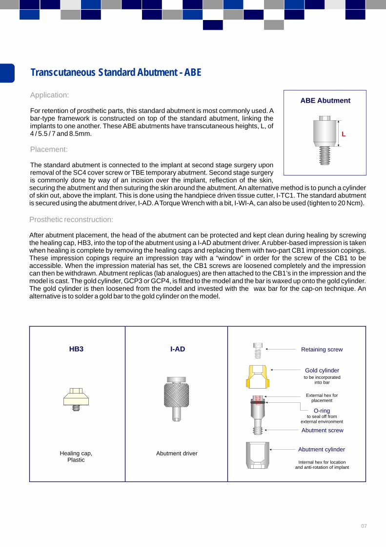
Transcutaneous Standard Abutment - ABE
Application:
Placement:
For retention of prosthetic parts, this standard abutment is most commonly used. A bar-type framework is constructed on top of the standard abutment, linking the implants to one another. These ABE abutments have transcutaneous heights, L, of 4 / 5.5 / 7 and 8.5mm.
The standard abutment is connected to the implant at second stage surgery upon removal of the SC4 cover screw or TBE temporary abutment. Second stage surgery is commonly done by way of an incision over the implant, reflection of the skin,securing the abutment and then suturing the skin around the abutment. An alternative method is to punch a cylinder of skin out, above the implant. This is done using the handpiece driven tissue cutter, I-TC1. The standard abutment is secured using the abutment driver, I-AD. A Torque Wrench with a bit, I-WI-A, can also be used (tighten to 20 Ncm).
After abutment placement, the head of the abutment can be protected and kept clean during healing by screwing the healing cap, HB3, into the top of the abutment using a I-AD abutment driver. A rubber-based impression is taken when healing is complete by removing the healing caps and replacing them with two-part CB1 impression copings. These impression copings require an impression tray with a “window” in order for the screw of the CB1 to be accessible. When the impression material has set, the CB1 screws are loosened completely and the impression can then be withdrawn. Abutment replicas (lab analogues) are then attached to the CB1’s in the impression and the model is cast. The gold cylinder, GCP3 or GCP4, is fitted to the model and the bar is waxed up onto the gold cylinder. The gold cylinder is then loosened from the model and invested with the wax bar for the cap-on technique. An alternative is to solder a gold bar to the gold cylinder on the model.
Prosthetic reconstruction:
L
ABE Abutment
HB3
Healing cap,Plastic
Abutment cylinder
Abutment screw
Gold cylinder
Retaining screw
to be incorporatedinto bar
External hex for placement
to seal off from
external environment
O-ring
Internal hex for locationand anti-rotation of implant
Abutment driver
I-AD
08 Southern Implants Cranio Facial Reconstruction ManualI I
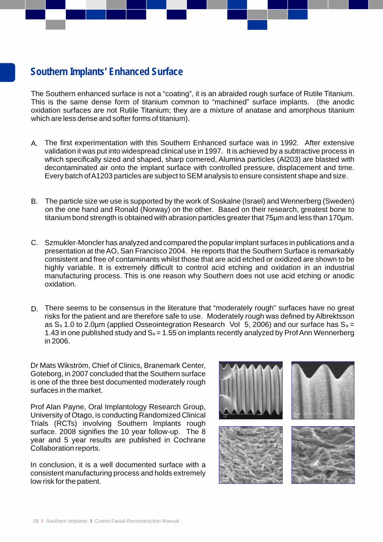
The Southern enhanced surface is not a “coating”, it is an abraided rough surface of Rutile Titanium. This is the same dense form of titanium common to “machined” surface implants. (the anodic oxidation surfaces are not Rutile Titanium; they are a mixture of anatase and amorphous titanium which are less dense and softer forms of titanium).
A.
B.
C.
D.
The first experimentation with this Southern Enhanced surface was in 1992. After extensive validation it was put into widespread clinical use in 1997. It is achieved by a subtractive process in which specifically sized and shaped, sharp cornered, Alumina particles (Al203) are blasted with decontaminated air onto the implant surface with controlled pressure, displacement and time. Every batch of A1203 particles are subject to SEM analysis to ensure consistent shape and size.
The particle size we use is supported by the work of Soskalne (Israel) and Wennerberg (Sweden) on the one hand and Ronald (Norway) on the other. Based on their research, greatest bone to titanium bond strength is obtained with abrasion particles greater that 75µm and less than 170µm.
Szmukler-Moncler has analyzed and compared the popular implant surfaces in publications and a presentation at the AO, San Francisco 2004. He reports that the Southern Surface is remarkably consistent and free of contaminants whilst those that are acid etched or oxidized are shown to be highly variable. It is extremely difficult to control acid etching and oxidation in an industrial manufacturing process. This is one reason why Southern does not use acid etching or anodic oxidation.
There seems to be consensus in the literature that “moderately rough” surfaces have no great risks for the patient and are therefore safe to use. Moderately rough was defined by Albrektsson as S 1.0 to 2.0µm (applied Osseointegration Research Vol 5, 2006) and our surface has S = 1.43 in one published study and S = 1.55 on implants recently analyzed by Prof Ann Wennerberg in 2006.
Dr Mats Wikström, Chief of Clinics, Branemark Center, Goteborg, in 2007 concluded that the Southern surface is one of the three best documented moderately rough surfaces in the market.
Prof Alan Payne, Oral Implantology Research Group, University of Otago, is conducting Randomized Clinical Trials (RCTs) involving Southern Implants rough surface. 2008 signifies the 10 year follow-up. The 8 year and 5 year results are published in Cochrane Collaboration reports.
In conclusion, it is a well documented surface with a consistent manufacturing process and holds extremely low risk for the patient.
aa
a
Southern Implants’ Enhanced Surface
Publication
09
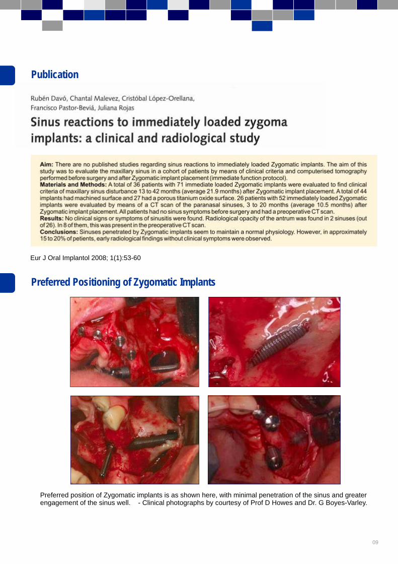
Preferred position of Zygomatic implants is as shown here, with minimal penetration of the sinus and greaterengagement of the sinus well. - Clinical photographs by courtesy of Prof D Howes and Dr. G Boyes-Varley.
Preferred Positioning of Zygomatic Implants
Eur J Oral Implantol 2008; 1(1):53-60

11
Introduction:
Indications:
Pre-operative examination and treatment planning:
Radiographic examination:
Patient Preparation:
This manual is produced as an adjunct to the Southern Implants Zygomatic Course, and as an instruction sheet for use before and during placement of these Zygomatic implants. It is not intended to be a guide for basic surgical techniques, as it is essential that practitioners using these implants are already experienced Maxillo-Facial or Cranio-Facial surgeons.
The main indications for the placement of Zygomatic implants are:
1. 2.3.
This must be done by the full team responsible for the complete treatment of the patient, usually a restorative Dentist or Prosthodontist in conjunction with a Maxillo-Facial or Cranio-Facial Surgeon. A full medical and dental history must be taken, with emphasis placed on the presence of soft tissue and hard tissue pathology and ensuring that the maxillary sinuses are clinically symptom-free. In addition, jaw relationships and resorption patterns must be noted.
As with any implant patient, a radiographic assessment is essential. As far as the Zygomatic protocol is concerned, the main objectives are twofold:
1.
2.
The following radiographic views should be taken as necessary:
1. 2.3.4.
5.
As zygomatic implants are generally placed under general anaesthetics, the standard protocol for patient preparation is adhered to. The part of the face above the zygomatic arch must be left uncovered when draping the patient or securing the endotrachael tube. Haemostasis is enhanced by the use of a suitable local anaesthetic infiltration in the entire operative area.
Patients who are fully edentulous in the maxilla, especially those with moderate to severe bone resorption.Patients who have unilateral or bilateral posterior maxillary edentulism, & with moderate to severe bone loss.Patients who have had ablative cancer surgery or who have suffered avulsive trauma to the middle third of the facial skeleton.
To detect the presence of any pathology in the maxillary sinuses, bearing in mind that the thickness of the antral mucosa should not exceed 6mm.To evaluate the volume of zygomatic bone available.
Panoramic view - for detection of pathology changes within the maxilla as well as anatomical structures.Occipitomental views to assess the extent of the maxillary sinus as well as the presence of sinus pathology.Lateral cephalogram to assess jaw relationships.CT scans. These must be in form of both axial cuts and reformatted images, as these give an excellent assessment of the maxillary sinuses. In the case of cancer and trauma surgery patients, 3D reconstructions are useful.Intra oral x-rays. These are essential to supplement the other views in cases where partially edentulousposterior segments are being reconstructed.
Zygomatic & Oncology Implants
12 Southern Implants Cranio Facial Reconstruction ManualI I
figure 1
figure 2
Operative Procedures
The Current Surgical Procedure is:
1.
2.
3.
4.
5.
6.
7.
8.
A crestal incision is made from just anterior to the maxillary tuberosity on one side to the same point on the other side. Three vertical releasing incisions are made in the second molar regions and the midline. These three incisions facilitate flap mobilization beyond the infraorbital margin. In unilateral cases, a hemimaxillary approach is used.
Before inserting the implant, ensure that the implant site is free of soft tissue remnants. Initial insertion of the implant is carried out using the machine connector to handpiece with the torque control set at 45Ncm at 15rpm.During insertion: 1. The implant must follow the prepared path of insertion.
2. Soft tissue must not be caught up on the implant surface. 3. Adequate coolant must be applied to both alveolar and zygomatic bone. 4. The torque controller is set at 45Ncm. Once this level is reached, further
insertion is achieved manually using the onion driver. When insertion is complete, rotate the implant head so that the hex is aligned correctly. The fixture mount is then removed and the cover screw placed by hand.
During insertion:During insertion: During insertion:
The buccal mucoperiosteal flaps are raised to expose the infraorbital nerve, the body of the zygoma and the zygomatic arch. A palatal flap is raised to expose the alveolar bone . The periosteum in the region of the upper molar teeth is incised to enhance flap mobility. A modified channel retractor is placed on the upper border of the zygomatic arch.
Suturing is carried out by the technique of choice using resorbable sutures. Thereafter a long-acting local anaesthetic solution is injected to control postoperative pain.
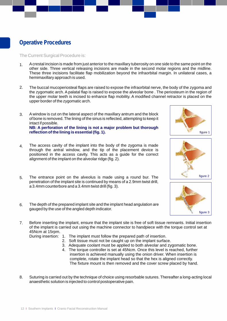
A window is cut on the lateral aspect of the maxillary antrum and the block of bone is removed. The lining of the sinus is reflected, attempting to keep it intact if possible.
NB: A perforation of the lining is not a major problem but thorough reflection of the lining is essential (fig. 1).
The access cavity of the implant into the body of the zygoma is made through the antral window, and the tip of the placement device is positioned in the access cavity. This acts as a guide for the correct alignment of the implant on the alveolar ridge (fig. 2).
The depth of the prepared implant site and the implant head angulation are gauged by the use of the angled depth indicator.
The entrance point on the alveolus is made using a round bur. The penetration of the implant site is continued by means of a 2.9mm twist drill, a 3.4mm counterbore and a 3.4mm twist drill (fig. 3).
figure 3

13
A further 8mg Decadron is given for 7 hours postoperatively. In addition, a course of oral antibiotics is given to the patient and a suitable analgesic regimen is prescribed. Occasionally a patient will complain of a feeling of congestion of the maxillary sinuses.In order to address this, a combination of nasal decongestant and cortisone nose drops is advised.
Patients may also complain of paraesthesia or anaesthesia in the distribution of the infraorbital nerve. This is transient and is due to stretching of the nerves during the operative procedure. These patients should therefore be counseled accordingly.
Modifications to the existing prosthesis will be necessary so that it can be worn during the integration phase. This should be carried out by the Prosthodontist or restorative Dentist.
Postoperative Management
Second Stage Surgery
It is common for these implants to be loaded immediately (same day or within a week of placement). However the well documented and conservative protocol, is exposure of implants performed 4 to 6 months after placement. This procedure may be carried out either under local or under general anaesthesia. It is recommended that impressions be taken at the time of implant exposure so that they can be splinted at the earliest opportunity. This is absolutely crucial in cases where bone grafting procedures have been performed. The surgical phase comprises exposure of the cover screws by means of a crestal incision and their replacement with temporary healing abutments. Suturing is then carried out according to the surgeons preference.
Should this occur, the implant should be removed. This is achieved by connecting a fixture mount and removing the implant by means of the onion driver. If any soft tissue is present in the implant site, this must be curetted out. In the unlikely event of the fracture of an implant, the coronal part is removed and the rest is left in site. Implants which have been removed due to non-integration may be replaced after a healing period of one year.
Non-integration of Implant
14 Southern Implants Cranio Facial Reconstruction ManualI I
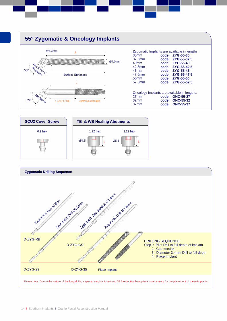
Please note: Due to the nature of the long drills, a special surgical insert and 32:1 reduction handpiece is necessary for the placement of these implants.
D-ZYG-29 D-ZYG-35 Place Implant
DRILLING SEQUENCE:Step1: Pilot Drill to full depth of implant 2: Countersink 3: Diameter 3.4mm Drill to full depth 4: Place Implant
D-ZYG-RB
D-ZYG-CS
Zygomatic Drilling Sequence
55º
55º
code: ZYG-55-35code: ZYG-55-37.5code: ZYG-55-40code: ZYG-55-42.5code: ZYG-55-45code: ZYG-55-47.5code: ZYG-55-50code: ZYG-55-52.5
Zygomatic Implants are available in lengths:35mm 37.5mm 40mm 42.5mm45mm47.5mm50mm52.5mm
Ø4.0mm
Ø4.3mmL
L
55° Zygomatic & Oncology Implants
0.9 hex
TB & WB Healing AbutmentsSCU2 Cover Screw
LØ4.5
1.22 hex
Ø5.5
1.22 hex
L
Oncology Implants are available in lengths:27mm 32mm 37mm
code: ONC-55-27code: ONC-55-32code: ONC-55-37
7, 12 or 17mm 20mm on all lengths

15
Prosthetic Options: Zygomatic & Oncology Platform
Temps Impression Coping Laboratory Analogue
Prosthetic Components Retention Screws
ZYG-55 / ONC-55
TCB 1h (Hex)TCB 1nh (Non-Hex)
TCB 5h (Hex)TCB 5nh (Non-Hex)
Titanium
OROR
OR
OR
OR
SB 1 (Hex)SB 5 (Non-Hex)
Plastic
GC-EX-40 (Hex)GC-NX-40 (Non-Hex)
Gold
CER-ZR-45 CER-ZR-46
MB DB
2 / 3.5 / 5 2 / 3.5 / 5
SB16 (Hex)SB-17-TT (Non-Hex)
UCLA
PASSIVEAbutment
ANATOMICALPost
CERAMICAbutments
Direct
Indi
rect
Uses 3 Series Screws
CC-NX-40 (Non-Hex)
Chrome Cobalt
OR
OR OR
DBS12 DBS24
OR
Gold
GCP3
TC9
Titanium
PC5
Plastic
LS1
OROR
OR
CB1Pick-up
CB2Transfer
GMC1
Gold
TMC
Titanium
LSMC1 PMC1
Plastic
OR OR
CMC1Pick-up
CMC2Transfer
HMC HMCT7
4/6Metal
PA-MC-48
Passive Abutment
ABZ
3 / 4 / 5 / 7 / 8.5
Standard Abutment
Compact Conical Abutment
AMCZ
1 / 2 / 3 / 4 / 5
OR
AMC17d-3or AMC30d-4
4/6Metal
OROR
P-CAP-40
Plastic
Plastic IIA-1
MIA-1Metal
LT7/10
DBN
2 / 4
Analogue for uncut DBN
LSDBN4
Plastic
Shouldered Abutment SB-DBN1Waxing sleeve for uncut DBN
TMCSL
Uses 3 Series Z Screws
HB
4/6Metal
HB3Plastic
Strengthener
Titanium
OR
OBZ
2 / 3 / 4 / 5
AO2
Brass
PC2
Plastic
Overdenture Abutment
Titanium Nitride Surface
Scalloped Scalloped
LS12
SCANNINGAbutment
CIA-EX-40 (Engaging)
SCU2
TB (one-part)T4B (two-part)
WB (one-part) T5B (two-part)
CBUPick-up
CBU-WPick-up
Narrow
Wide
ø5.5
ø4.5
CBU70Transfer
CBU75Transfer
GSUZ2
TSHZ2GSQZ2
GSSZ2
GSUZ2
TSHZ2GSQZ2
GSSZ2
GSUZ3GSSZ3
GSQZ3 TSHZ3
GSUZ9TSUZ9
GSS1
TSS1
TSH1
GSU1
GSH1
TSU1
16 Southern Implants Cranio Facial Reconstruction ManualI I 17

Zygomatic Instruments
I-ZYG Zygomatic Tray
20 Southern Implants Cranio Facial Reconstruction ManualI I
I-CON-XConnector tohandpiece
55°Fixture Mount
I-ZYG-DH-1Placementappliance
I-ZYG-INS-1Onion driver
I-IMP-INS-1Implant Insert
I-ZYG-RET-1Retractor
I-ZYG-DG-1Depth gauge
* Additional Instruments: These are optional extras to assist with placement and can be manufactured on request
*
*
I-HD I-CS-HD
I-CON-X
I-ZYG-DG-1
I-ZYG-DH
D-ZYG-RB
D-ZYG-29
D-ZYG-35
D-ZYG-CS
ZYG-TR-55-55
ZYG-TR-55-45
ZYG-TR-55-35
Southern Implants (Pty) Ltd. Irene, South Africa
STERILE R
2
!
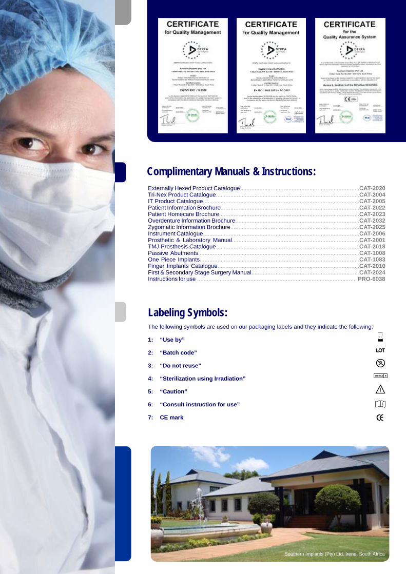
Externally Hexed Product CatalogueTri-Nex Product Catalogue IT Product CataloguePatient Information BrochurePatient Homecare BrochureOverdenture Information BrochureZygomatic Information BrochureInstrument CatalogueProsthetic & Laboratory ManualTMJ Prosthesis CataloguePassive AbutmentsOne Piece ImplantsFinger Implants CatalogueFirst & Secondary Stage Surgery ManualInstructions for use
...................................................................................................................................................................
................................................................................................................................................................................................................................ ............................................
............................... .............................................................................. ............................................
.................................................................................................
................................................................................................................................................................................................................................................................................................
...........................................................................................................................................................
...................................................................................................
CAT-2020CAT-2004CAT-2005CAT-2022
.. CAT-2023
.. CAT-2032
.. CAT-2025CAT-2006
...............................................................................CAT-2001CAT-2018CAT-1008CAT-1083CAT-2010CAT-2024PRO-6038
The following symbols are used on our packaging labels and they indicate the following:
1: “Use by”
2: “Batch code”
3: “Do not reuse”
4: “Sterilization using Irradiation”
5: “Caution”
6: “Consult instruction for use”
7: CE mark
Complimentary Manuals & Instructions:
Labeling Symbols:
i

AustraliaHenry Schein I Halas DentalTel: +61 2 9697 6288Fax: +61 2 9697 [email protected]
New ZealandSouthern Implants Ltd NZTel: 0800 246 752Cel: +64 2189 4243Fax: +64 9 430 [email protected]
BeneluxProScan bvbaTel: +32 11 822 650Fax: +32 11 822 [email protected]
GreeceSouthern ImplantsTel: +30 210 898 2817Fax: +30 210 595 [email protected]
United KingdomSouthern Implants UKTel: +44 208 998 0063Fax: +44 208 997 [email protected]
Southern ImplantsTel: +49 7121 490 620Fax: +49 7121 491 [email protected]
GermanyAmericas / AsiaSouthern Implants Inc.Tel: +1 949 273 8505 Fax: +1 949 273 [email protected] www.southernimplants.us
Nordic CountriesProtera ABTel: +46 31 291078Fax: +46 706 [email protected]
South AfricaSouthern Implants (Pty) Ltd.Tel: +27 12 667 1046Fax: +27 12 [email protected]
Spain / PortugalContactodentTel: +351 214 693 332Fax: +351 214 693 [email protected]
TurkeyEkodentTel: +212 343 [email protected]
NamibiaSkydancerTel: +64 61 225 152Fax: +64 61 235 [email protected]
EXPANDING PROVEN CONCEPTS