Embed Size (px)
DESCRIPTION
How to install crankset
Citation preview
Toll Free: Mon. - Fri., 7:00 a.m. to 5:00 p.m. PST • 1 800 423-2420 3
MTB TECHNOLOGY
FRONT CHAINWHEEL: Installation
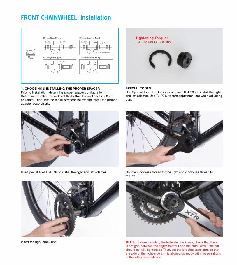
1. CHOOSING & INSTALLING THE PROPER SPACERPrior to installation, determine proper spacer configuration.Determine whether the width of the bottom bracket shell is 68mm or 73mm. Then, refer to the illustrations below and install the proper adapter accordingly.
SPECIAL TOOLSUse Special Tool TL-FC32 (spanner) and TL-FC35 to install the right and left adapter. Use TL-FC17 to turn adjustment nut when adjusting play.
Use Special Tool TL-FC32 to install the right and left adapter.
Insert the right crank unit. NOTE: Before installing the left-side crank arm, check that there is not gap between the adjustmentnut and the crank arm. (The nut should be fully tightened.) Then, set the left-side crank arm so that the axle of the right-side arm is aligned correctly with the serrations of the left-side crank arm.
Counterclockwise thread for the right and clockwise thread for the left.
Technical Service Instructions SI-15H0A
General Safety Information
Front chainwheelFC-M970
Specifications
Installation of the front chainwheel
WARNING• The fixing bolt for the left-side crank arm must be tightened to 45 – 55 N·m using a
torque wrench. After the bicycle has been ridden for approximately 100 km (60 miles)or in the event of a crash, the fixing bolt should be rechecked using a torque wrench.Inadequate tightening of the fixing bolt could cause the crank arm to fall off whileriding, resulting in a serious accident.
• Before riding, you should carefully check your crankset to make sure that there are nocracks, and if you find any sign of a crack or any other unusual condition, do NOT usethe bicycle.
• Be careful not to let the cuffs of your clothes get caught in the chain while riding,otherwise you may fall off the bicycle.
• Check that the tension of the chain is correct and that the chain is not damaged. If thetension is too weak or the chain is damaged, the chain should be replaced. If this isnot done, the chain may break cause serious injury.
• Obtain and read the service instructions carefully prior to installing the parts. Loose,worn, or damaged parts may cause injury to the rider.We strongly recommend only using genuine Shimano replacement parts.
• Read these Technical Service Instructions carefully, and keep them in a safe place forlater reference.
Note• Make sure that the chainring combination matches the front chainwheel tooth
configuration in the Product specifications table. If other combinations are used, thedistance between the chainrings will be incorrect and the chain might slip off and getcaught in between them.
• When the chain is in the position shown in theillustration, the chain may contact the frontchainrings or front derailleur and generatenoise. If the noise is a problem, shift the chainonto the next-larger rear sprocket or the oneafter.
• Before riding the bicycle, check that there is noplay or looseness in the connection. Also, besure to retighten the crank arm fixing bolt at periodic intervals. (BB-FC, FC-PD)
• If you feel any looseness in the bottom bracket axle, the bottom bracket should bereplaced.
• In addition, if pedaling performance does not feel normal, check this once more.• Do not wash the bottom bracket with high-pressure jets of water.• Apply grease to the bottom bracket before installing it.• To ensure the best performance, be sure to use only the specified type of chain. The
wide type of chain cannot be used.• If the chain keeps coming off the chainrings during use, replace the chainrings and the
chain.• You should periodically wash the chainrings in a neutral detergent and then lubricate
them again. In addition, cleaning the chain with neutral detergent and lubricating it canbe an effective way of extending the useful life of the chainrings and the chain.
• Parts are not guaranteed against natural wear or deterioration resulting from normaluse.
• For maximum performance we highly recommend Shimano lubricants andmaintenance products.
• For any questions regarding methods of installation, adjustment, maintenance oroperation, please contact a professional bicycle dealer.
Follow the procedure in the figure.1, 2 Use the special tool TL-FC32 to install the right adapter (counterclockwise thread) and the left
adapter (clockwise thread).Tightening torque: 35 - 50 N·m {305 - 435 in. lbs.}
3 Insert the right crank unit.
4 Before installing the left-side crank arm, check that there is no gap between the adjustment nut andthe crank arm (the nut should be fully tightened), and then set the left-side crank arm so that the axleof the right-side crank arm unit is aligned correctly with the serrations of the left-side crank arm.
5 Insert an 8 mm Allen key and turn it clockwise to tighten the crank arm fixing bolt.Note: The crank arm fixing bolt should be periodically retightened.Tightening torque: 45 - 55 N·m {392 - 479 in. lbs.}
6 Use the TL-FC17 to turn the adjustment nut in order to adjust the play, and then tighten theadjustment nut fixing bolt (2.5 mm Allen key).Tightening torque: Adjustment nut / 1 - 1.5 N·m {8.7 - 13 in. lbs.}
Adjustment nut fixing bolt / 1 - 1.2 N·m {8.7 - 10.4 in. lbs.}
7 Turn the TL-FC35 counterclockwise to install the crank arm cap.Note: At the time of shipment from the factory, the crank arm cap is installed to the crank arm, and
so use the TL-FC35 to check that it is securely tightened.
• Be sure to read the service instructions for the Front Drive Systemin conjunction with these service instructions.
Frontchainrings
Rearsprockets
Crank arm fixing bolt
Crank arm cap
TL-FC35
TL-FC35
8 mm Allen key
Left-side crank arm
Spacer installation method1 Check whether the width of the bottom bracket shell
is 68 mm or 73 mm.2 Next, install the adapter while referring to the
illustrations below.68mm73mm
Removal1 Turn the TL-FC35 clockwise to
remove the crank arm cap.
Note: The crank arm cap and the TL-FC35 screw have a left-handthread [reverse thread].This is to prevent the crank armfrom turning also when removingthe crank arm fixing bolt.
2 Turn the TL-FC35 counterclockwiseto tighten it as far as it will go.Check that the TL-FC35 turns 3.5times or more at this time.(Because of the design, the threadmay become stripped if less than3.5 threads are engaged.)
3 Fit an 8 mm Allen key and turn itcounterclockwise to remove theleft-side crank arm.
5
2
7
6
41
3
Axle
TL-FC17
TL-FC35
TL-FC32
8 mm Allen key
2.5 mm Allen key
Adjustment nut
Adjustment nut fixing bolt
Model number
Chainwheel tooth combination
Bolt circle diameter
Crank arm length
Chain line
Shell width
Thread dimensions
FC-M970
44-32-22T / 44-32-24T
104 mm / 64 mm
165 mm, 167.5 mm, 170 mm, 172.5 mm, 175 mm, 177.5 mm, 180 mm
50 mm
68, 73 mm
BC1.37 (68, 73 mm)
68 mm (Band Type) 68 mm (Bracket Type)
73 mm (Band Type) 73 mm (Bracket Type)
(2.5 mm)
(2.5 mm)
(2.5 mm) (2.5 mm)(2.5 mm)
E-type bracket
For bracket typeInstall as shown in theillustration.
Bolt
AdapterAdapter
Front Derailleur
Front Chainwheel
Tightening torque : 35 - 50 N·m {305 - 435 in. lbs.}
One Holland, Irvine, California 92618, U.S.A. Phone: +1-949-951-5003
Industrieweg 24, 8071 CT Nunspeet, The Netherlands Phone: +31-341-272222 3-77 Oimatsu-cho Sakai-ku, Sakai, Osaka 590-8577, Japan
Please note: specifications are subject to change for improvement without notice. (English) © Jun. 2006 by Shimano Inc. XBC IZM Printed in Japan.
Tightening Torque:0.3 - 0.5 Nm {3 - 4 in. lbs.}
All prices subject to change. © 2008 Shimano American Corporation. All Rights Reserved.4
MTB TECHNOLOGY
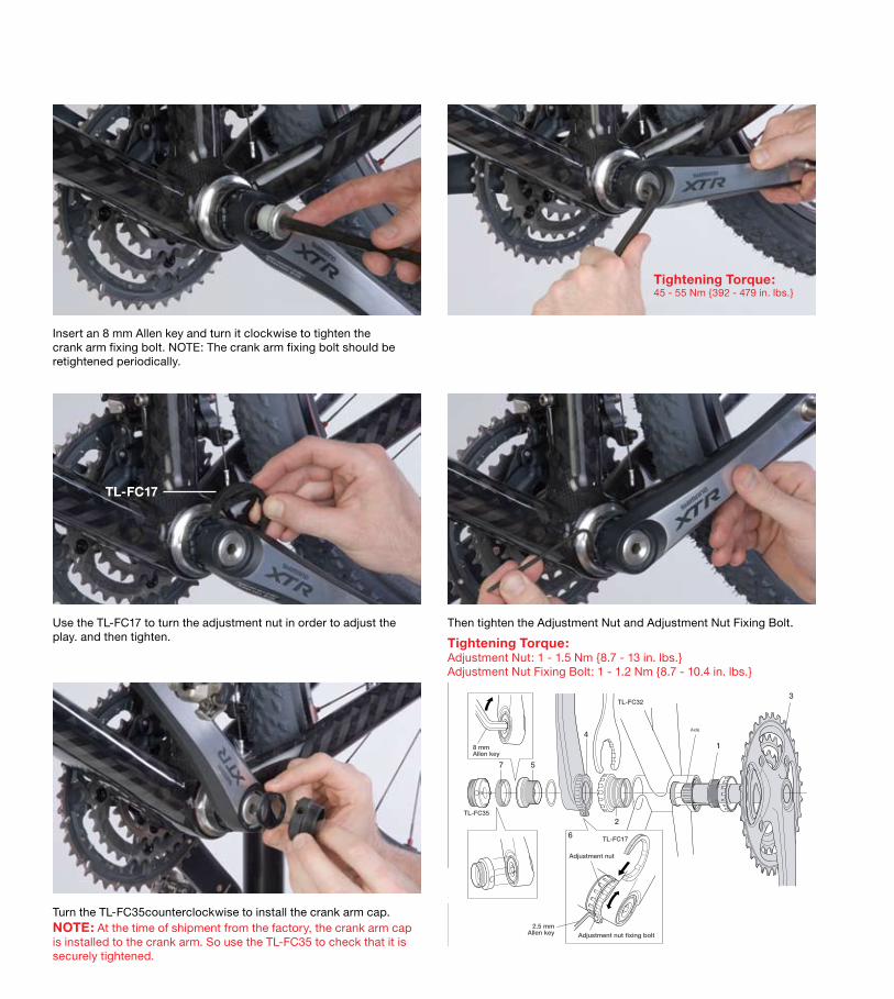
Insert an 8 mm Allen key and turn it clockwise to tighten the crank arm fixing bolt. NOTE: The crank arm fixing bolt should be retightened periodically.
Use the TL-FC17 to turn the adjustment nut in order to adjust the play. and then tighten.
Turn the TL-FC35counterclockwise to install the crank arm cap. NOTE: At the time of shipment from the factory, the crank arm cap is installed to the crank arm. So use the TL-FC35 to check that it is securely tightened.
Then tighten the Adjustment Nut and Adjustment Nut Fixing Bolt.
Tightening Torque:45 - 55 Nm {392 - 479 in. lbs.}
Tightening Torque:Adjustment Nut: 1 - 1.5 Nm {8.7 - 13 in. lbs.}Adjustment Nut Fixing Bolt: 1 - 1.2 Nm {8.7 - 10.4 in. lbs.}
Technical Service Instructions SI-15H0A
General Safety Information
Front chainwheelFC-M970
Specifications
Installation of the front chainwheel
WARNING• The fixing bolt for the left-side crank arm must be tightened to 45 – 55 N·m using a
torque wrench. After the bicycle has been ridden for approximately 100 km (60 miles)or in the event of a crash, the fixing bolt should be rechecked using a torque wrench.Inadequate tightening of the fixing bolt could cause the crank arm to fall off whileriding, resulting in a serious accident.
• Before riding, you should carefully check your crankset to make sure that there are nocracks, and if you find any sign of a crack or any other unusual condition, do NOT usethe bicycle.
• Be careful not to let the cuffs of your clothes get caught in the chain while riding,otherwise you may fall off the bicycle.
• Check that the tension of the chain is correct and that the chain is not damaged. If thetension is too weak or the chain is damaged, the chain should be replaced. If this isnot done, the chain may break cause serious injury.
• Obtain and read the service instructions carefully prior to installing the parts. Loose,worn, or damaged parts may cause injury to the rider.We strongly recommend only using genuine Shimano replacement parts.
• Read these Technical Service Instructions carefully, and keep them in a safe place forlater reference.
Note• Make sure that the chainring combination matches the front chainwheel tooth
configuration in the Product specifications table. If other combinations are used, thedistance between the chainrings will be incorrect and the chain might slip off and getcaught in between them.
• When the chain is in the position shown in theillustration, the chain may contact the frontchainrings or front derailleur and generatenoise. If the noise is a problem, shift the chainonto the next-larger rear sprocket or the oneafter.
• Before riding the bicycle, check that there is noplay or looseness in the connection. Also, besure to retighten the crank arm fixing bolt at periodic intervals. (BB-FC, FC-PD)
• If you feel any looseness in the bottom bracket axle, the bottom bracket should bereplaced.
• In addition, if pedaling performance does not feel normal, check this once more.• Do not wash the bottom bracket with high-pressure jets of water.• Apply grease to the bottom bracket before installing it.• To ensure the best performance, be sure to use only the specified type of chain. The
wide type of chain cannot be used.• If the chain keeps coming off the chainrings during use, replace the chainrings and the
chain.• You should periodically wash the chainrings in a neutral detergent and then lubricate
them again. In addition, cleaning the chain with neutral detergent and lubricating it canbe an effective way of extending the useful life of the chainrings and the chain.
• Parts are not guaranteed against natural wear or deterioration resulting from normaluse.
• For maximum performance we highly recommend Shimano lubricants andmaintenance products.
• For any questions regarding methods of installation, adjustment, maintenance oroperation, please contact a professional bicycle dealer.
Follow the procedure in the figure.1, 2 Use the special tool TL-FC32 to install the right adapter (counterclockwise thread) and the left
adapter (clockwise thread).Tightening torque: 35 - 50 N·m {305 - 435 in. lbs.}
3 Insert the right crank unit.
4 Before installing the left-side crank arm, check that there is no gap between the adjustment nut andthe crank arm (the nut should be fully tightened), and then set the left-side crank arm so that the axleof the right-side crank arm unit is aligned correctly with the serrations of the left-side crank arm.
5 Insert an 8 mm Allen key and turn it clockwise to tighten the crank arm fixing bolt.Note: The crank arm fixing bolt should be periodically retightened.Tightening torque: 45 - 55 N·m {392 - 479 in. lbs.}
6 Use the TL-FC17 to turn the adjustment nut in order to adjust the play, and then tighten theadjustment nut fixing bolt (2.5 mm Allen key).Tightening torque: Adjustment nut / 1 - 1.5 N·m {8.7 - 13 in. lbs.}
Adjustment nut fixing bolt / 1 - 1.2 N·m {8.7 - 10.4 in. lbs.}
7 Turn the TL-FC35 counterclockwise to install the crank arm cap.Note: At the time of shipment from the factory, the crank arm cap is installed to the crank arm, and
so use the TL-FC35 to check that it is securely tightened.
• Be sure to read the service instructions for the Front Drive Systemin conjunction with these service instructions.
Frontchainrings
Rearsprockets
Crank arm fixing bolt
Crank arm cap
TL-FC35
TL-FC35
8 mm Allen key
Left-side crank arm
Spacer installation method1 Check whether the width of the bottom bracket shell
is 68 mm or 73 mm.2 Next, install the adapter while referring to the
illustrations below.68mm73mm
Removal1 Turn the TL-FC35 clockwise to
remove the crank arm cap.
Note: The crank arm cap and the TL-FC35 screw have a left-handthread [reverse thread].This is to prevent the crank armfrom turning also when removingthe crank arm fixing bolt.
2 Turn the TL-FC35 counterclockwiseto tighten it as far as it will go.Check that the TL-FC35 turns 3.5times or more at this time.(Because of the design, the threadmay become stripped if less than3.5 threads are engaged.)
3 Fit an 8 mm Allen key and turn itcounterclockwise to remove theleft-side crank arm.
5
2
7
6
41
3
Axle
TL-FC17
TL-FC35
TL-FC32
8 mm Allen key
2.5 mm Allen key
Adjustment nut
Adjustment nut fixing bolt
Model number
Chainwheel tooth combination
Bolt circle diameter
Crank arm length
Chain line
Shell width
Thread dimensions
FC-M970
44-32-22T / 44-32-24T
104 mm / 64 mm
165 mm, 167.5 mm, 170 mm, 172.5 mm, 175 mm, 177.5 mm, 180 mm
50 mm
68, 73 mm
BC1.37 (68, 73 mm)
68 mm (Band Type) 68 mm (Bracket Type)
73 mm (Band Type) 73 mm (Bracket Type)
(2.5 mm)
(2.5 mm)
(2.5 mm) (2.5 mm)(2.5 mm)
E-type bracket
For bracket typeInstall as shown in theillustration.
Bolt
AdapterAdapter
Front Derailleur
Front Chainwheel
Tightening torque : 35 - 50 N·m {305 - 435 in. lbs.}
One Holland, Irvine, California 92618, U.S.A. Phone: +1-949-951-5003
Industrieweg 24, 8071 CT Nunspeet, The Netherlands Phone: +31-341-272222 3-77 Oimatsu-cho Sakai-ku, Sakai, Osaka 590-8577, Japan
Please note: specifications are subject to change for improvement without notice. (English) © Jun. 2006 by Shimano Inc. XBC IZM Printed in Japan.
TL-FC17
Toll Free: Mon. - Fri., 7:00 a.m. to 5:00 p.m. PST • 1 800 423-2420 5
MTB TECHNOLOGY
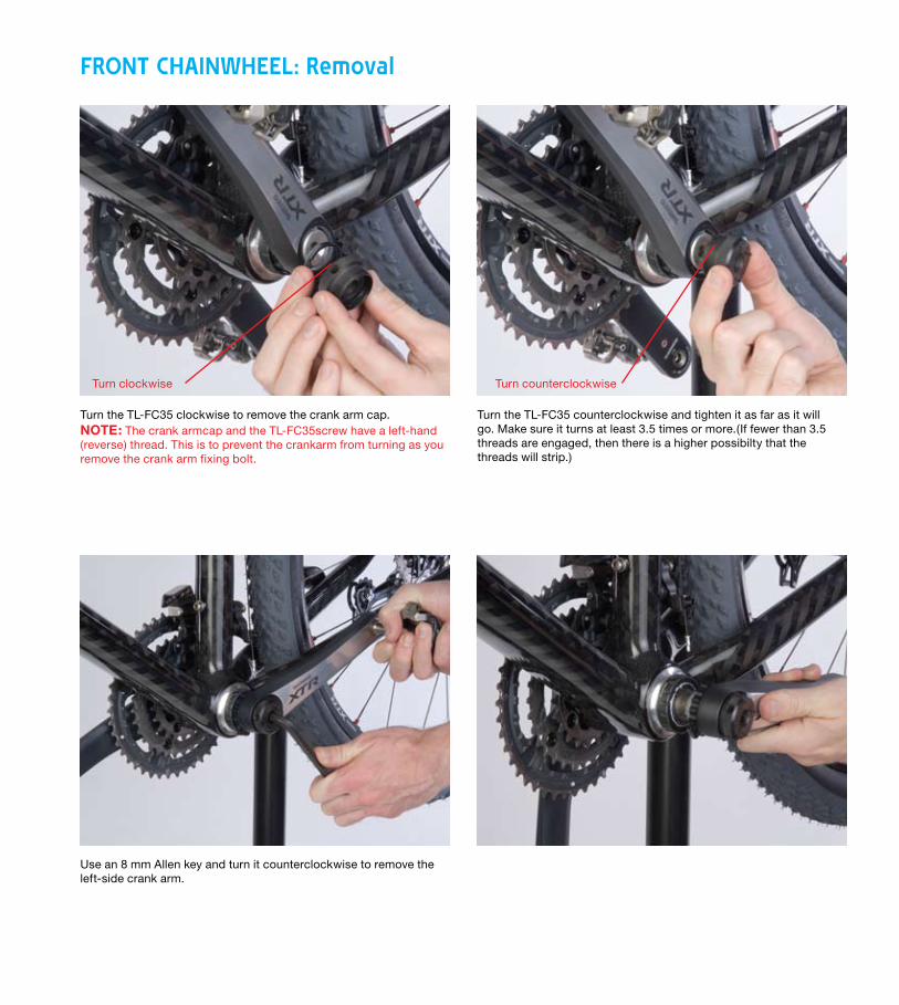
Turn the TL-FC35 clockwise to remove the crank arm cap. NOTE: The crank armcap and the TL-FC35screw have a left-hand (reverse) thread. This is to prevent the crankarm from turning as you remove the crank arm fixing bolt.
Turn the TL-FC35 counterclockwise and tighten it as far as it will go. Make sure it turns at least 3.5 times or more.(If fewer than 3.5 threads are engaged, then there is a higher possibilty that the threads will strip.)
Use an 8 mm Allen key and turn it counterclockwise to remove the left-side crank arm.
FRONT CHAINWHEEL: Removal
Turn clockwise Turn counterclockwise
All prices subject to change. © 2008 Shimano American Corporation. All Rights Reserved.6
MTB TECHNOLOGY
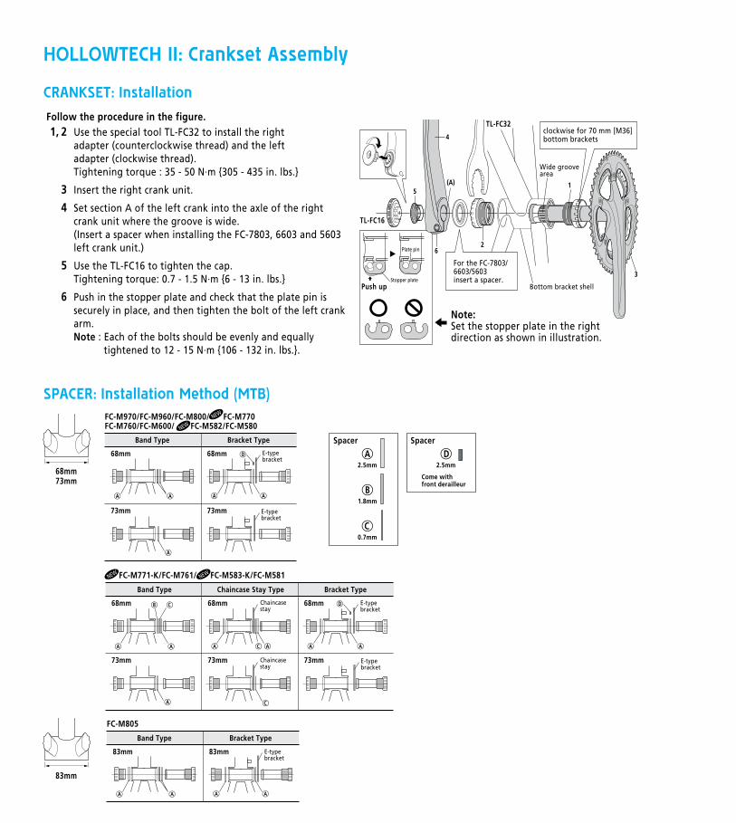
CRANKSET: Installation
SPACER: Installation Method (MTB)
HOLLOWTECH II crankset assembly
Use the special tool TL-FC32 to install the right adapter (counterclockwise thread) and the left adapter (clockwise thread).Tightening torque : 35 - 50 N·m {305 - 435 in. lbs.}
Insert the right crank unit.
Set section A of the left crank into the axle of the right crank unit where the groove is wide.(Insert a spacer when installing the FC-7803, 6603 and 5603 left crank unit.)
Use the TL-FC16 to tighten the cap.Tightening torque: 0.7 - 1.5 N·m {6 - 13 in. lbs.}
Push in the stopper plate and check that the plate pin is securely in place, and then tighten the bolt of the left crank arm.Note : Each of the bolts should be evenly and equally
tightened to 12 - 15 N·m {106 - 132 in. lbs.}.
1, 2
3
4
5
6
Wide groove area
Bottom bracket shell
TL-FC16
TL-FC32
Follow the procedure in the figure.
Chaincasestay
Chaincasestay
Band Type Chaincase Stay Type Bracket Type
68mm 68mm
73mm 73mm
68mm
73mm
68mm
73mm
68mm
73mm
Band Type Bracket Type
A
CB E-typebracket
Come with front derailleur
E-typebracket
E-typebracket
A
A
AA A A
D
A
AA A A
D
E-typebracket
83mm 83mm
Band Type Bracket Type
E-typebracket
AA A A
2.5mm
A
1.8mm
B
0.7mm
C
C
C
68mm73mm
83mm
Spacer
2.5mm
DSpacer
FC-M970/FC-M960/FC-M800/ FC-M770FC-M760/FC-M600/ FC-M582/FC-M580
FC-M805
FC-M771-K/FC-M761/ FC-M583-K/FC-M581
Installation of the crankset
Spacer installation method (MTB)
5
2
4
(A) 1
3Stopper plate
Plate pin
Push up
6
clockwise for 70 mm [M36] bottom brackets
WENWEN
WEN WEN
For the FC-7803/6603/5603insert a spacer.
Note:Set the stopper plate in the right direction as shown in illustration.
HOLLOWTECH II: Crankset Assembly