Embed Size (px)
Citation preview
Creative Approaches to
Truss Analysis Using BrR
2016 AASHTO RADBUG Meeting
August 2-3, 2016
Chicago, IL
George Huang, PhD, PE
California Department of Transportation
1
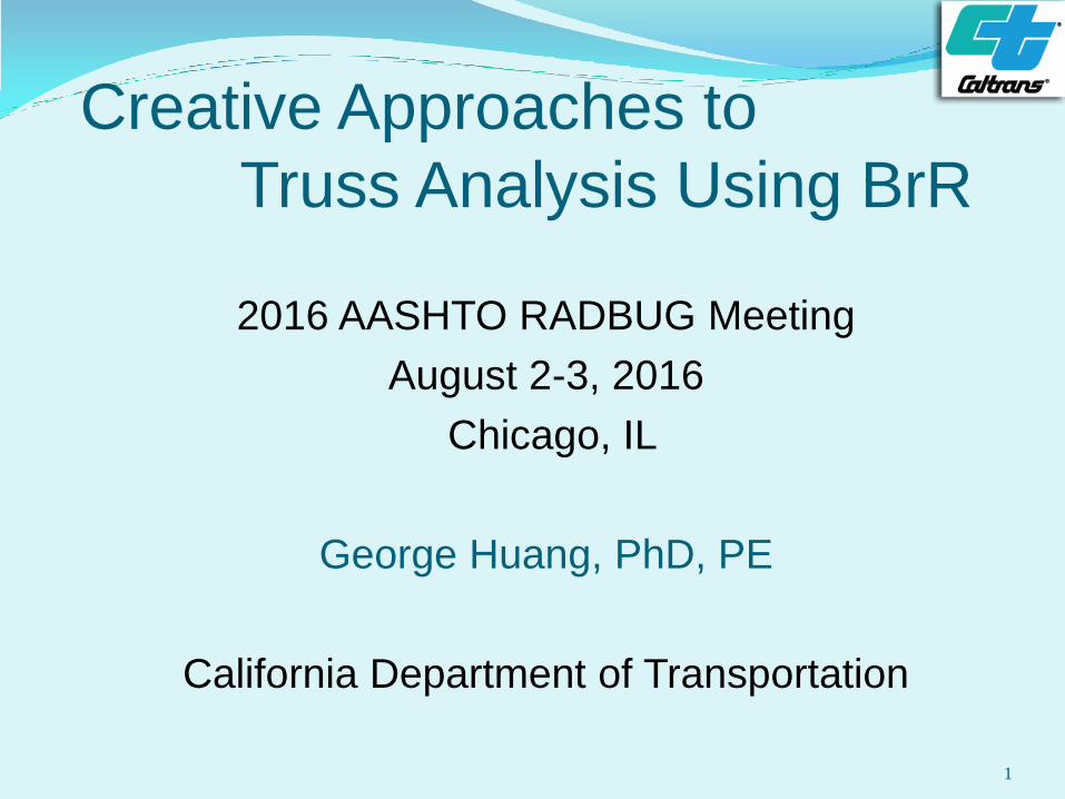
Introduction
In California, permit trucks were always rated with
the adjacent lane of HS20 load for truss bridges.
We only started to use BrR regularly for truss
bridge three years ago after this function was
added.
In BrR, only axial load members can be used for
the truss model.
The truss spans and non truss spans are
modeled separately.
Relation between different truss points can be
connected only with truss member.
2
Introduction (Cont.) Features from some truss bridges may seem
beyond the application limits of BrR:
(1) Girders of non-truss span rested on
members of truss span.
(2) Two vertical members connected at one joint.
(3) Members connected with pins and hanger.
(4) Members taking shear load.
This presentation will show examples of how to
handle these special features with BrR.
3
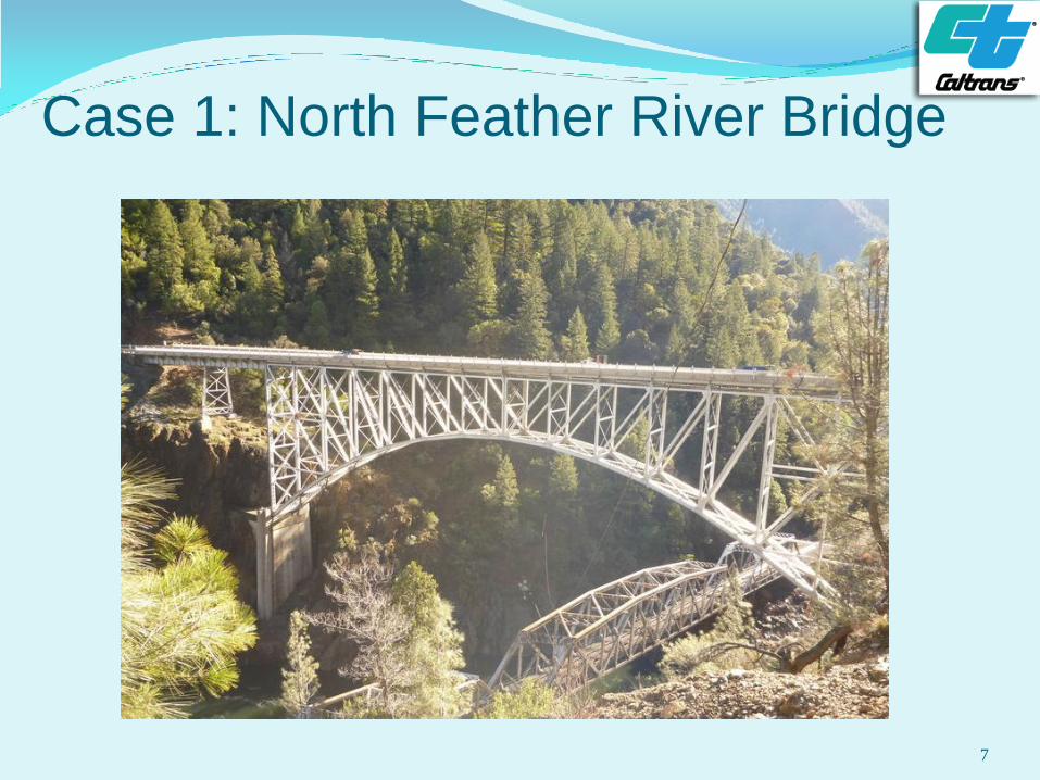
Case 1: North Feather River Bridge (Br. No.12 0038)
Built in 1932 and strengthened in 2006.
One deck truss span (350 ft) with concrete deck on
stringers and floor beams.
Five simple approach spans (44 to 82 ft) with
concrete deck on floor beams and two main girders.
Girders of the approach spans are directly
connected to the truss members.
There is an open expansion joint at the middle of
truss span.
4
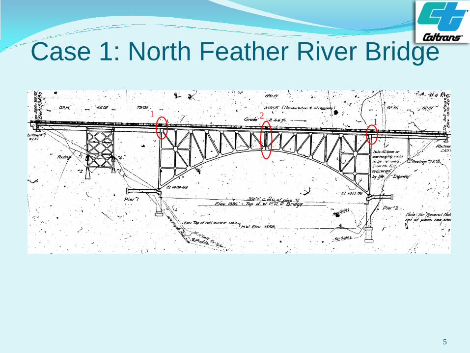
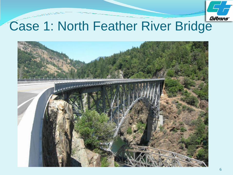
Case 1: North Feather River Bridge
5
1 2 1
Case 1: North Feather River Bridge
6
Case 1: North Feather River Bridge
7
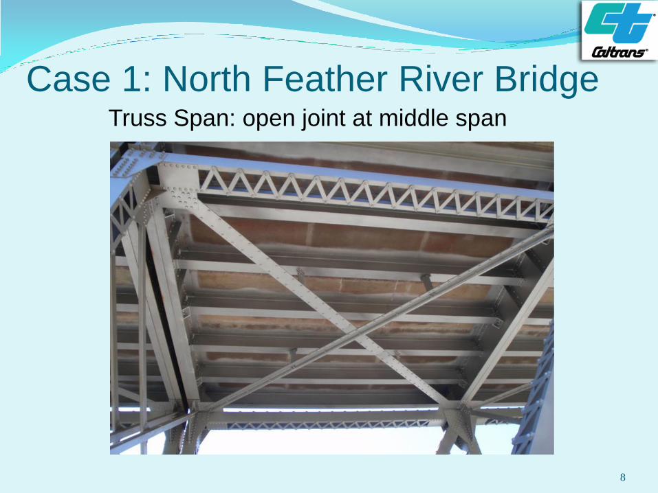
Case 1: North Feather River Bridge Truss Span: open joint at middle span
8
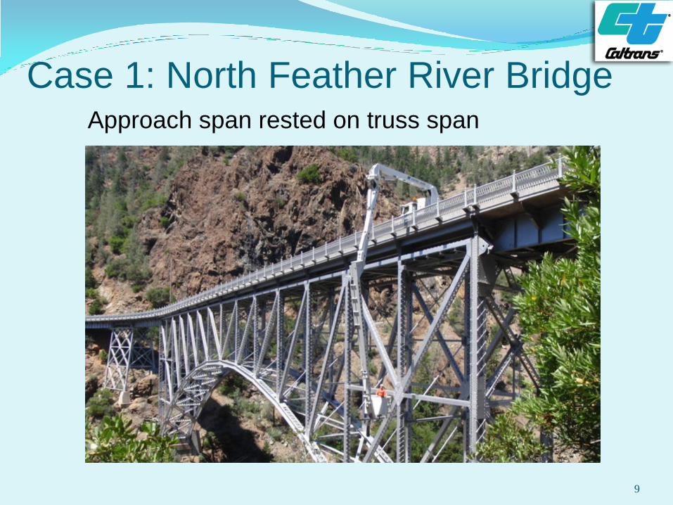
Case 1: North Feather River Bridge Approach span rested on truss span
9
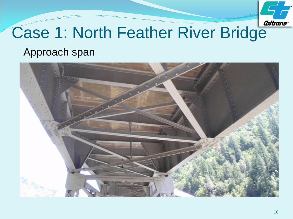
Case 1: North Feather River Bridge Approach span
10
Case 1: North Feather River Bridge
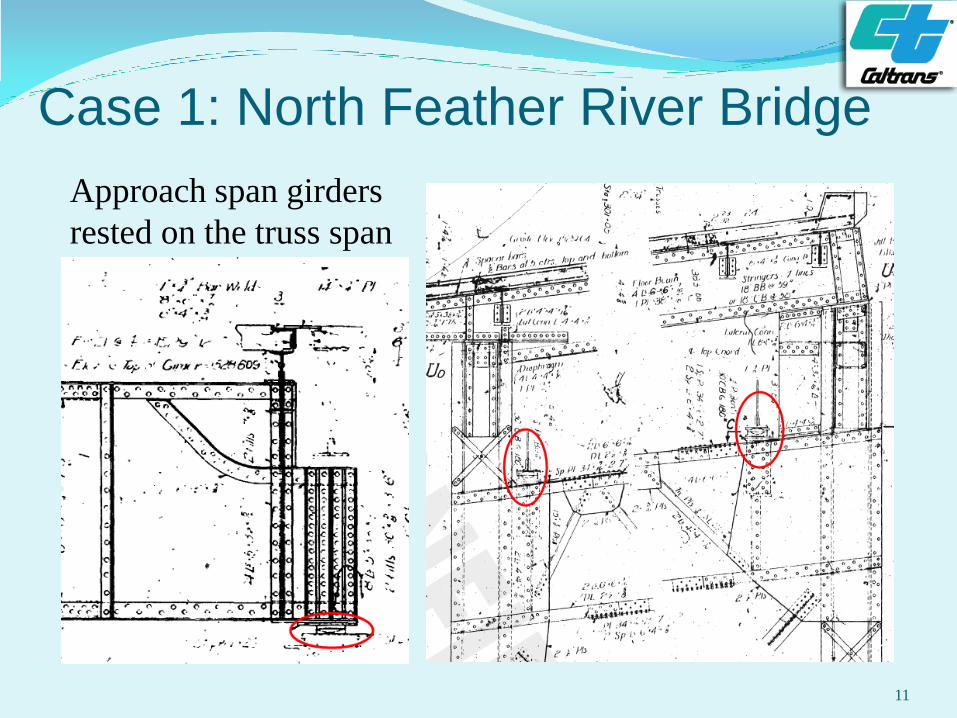
11
Approach span girders
rested on the truss span
Case 1: North Feather River Bridge
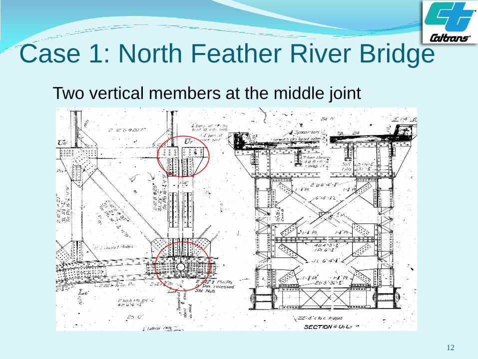
12
Two vertical members at the middle joint
Case 1: North Feather River Bridge
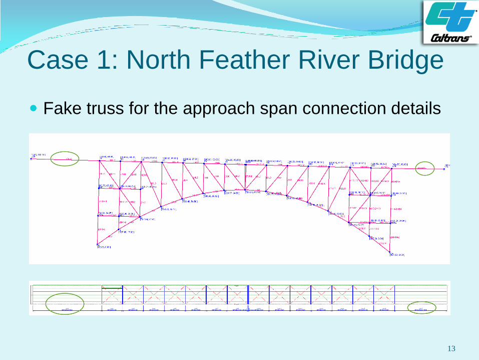
13
Fake truss for the approach span connection details
Case 1: North Feather River Bridge
14
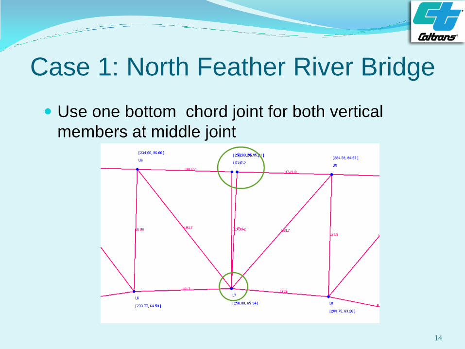
Use one bottom chord joint for both vertical
members at middle joint
Case 1: North Feather River Bridge
15
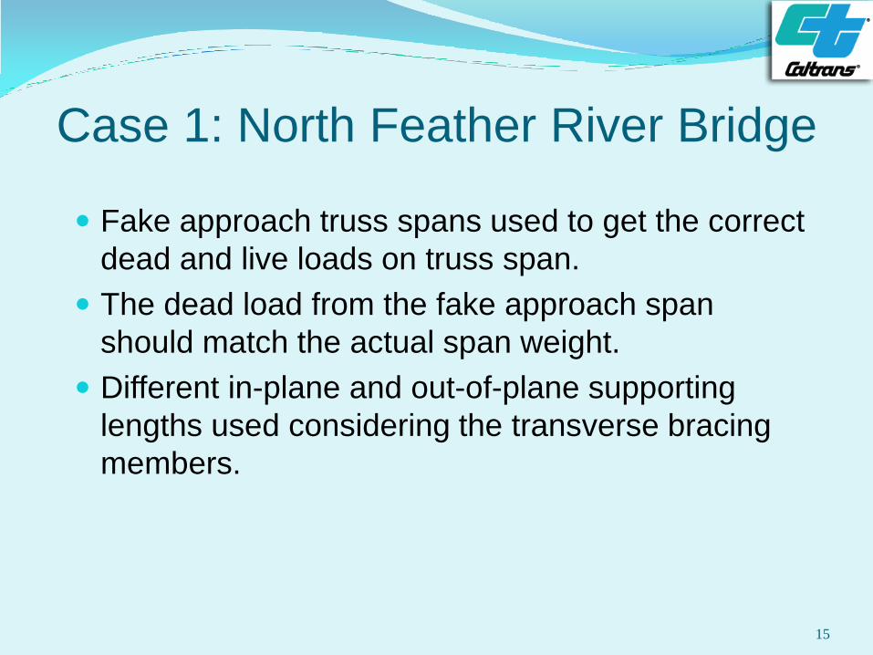
Fake approach truss spans used to get the correct
dead and live loads on truss span.
The dead load from the fake approach span
should match the actual span weight.
Different in-plane and out-of-plane supporting
lengths used considering the transverse bracing
members.
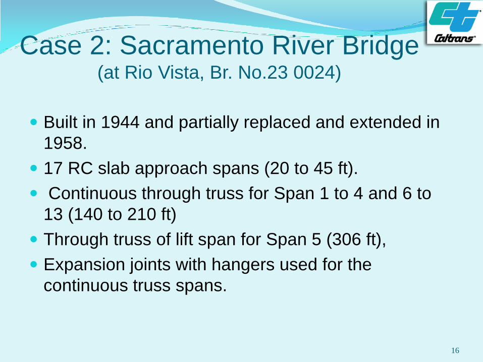
Case 2: Sacramento River Bridge (at Rio Vista, Br. No.23 0024)
Built in 1944 and partially replaced and extended in
1958.
17 RC slab approach spans (20 to 45 ft).
Continuous through truss for Span 1 to 4 and 6 to
13 (140 to 210 ft)
Through truss of lift span for Span 5 (306 ft),
Expansion joints with hangers used for the
continuous truss spans.
16
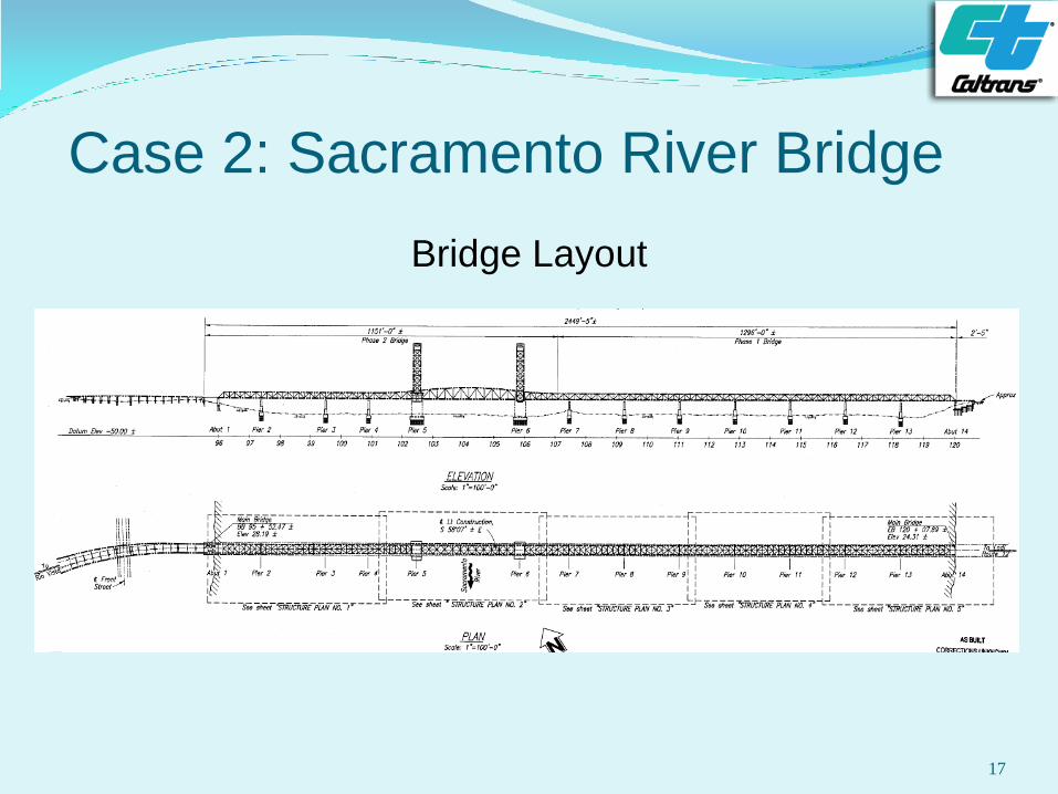
Case 2: Sacramento River Bridge
Bridge Layout
17
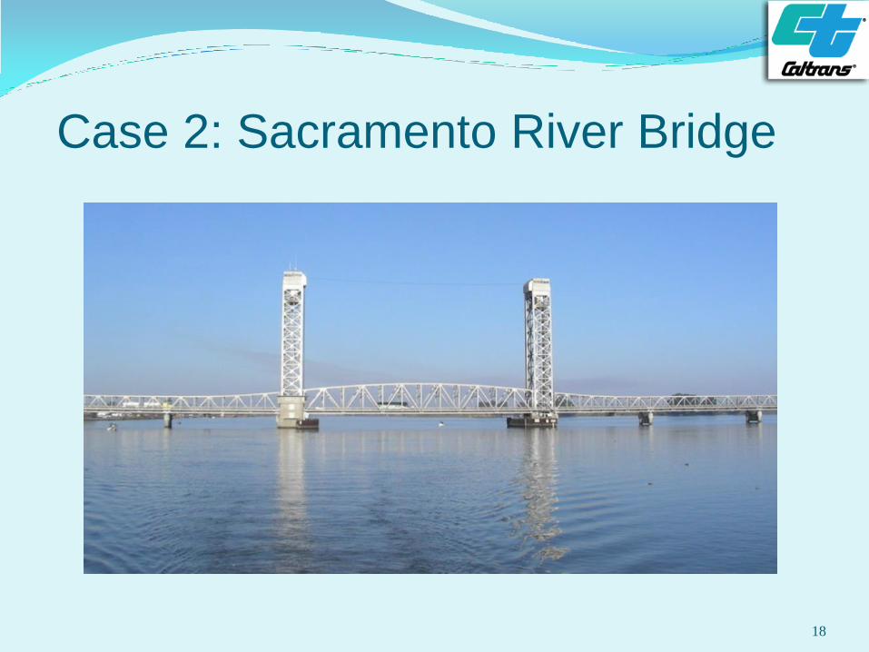
Case 2: Sacramento River Bridge
18
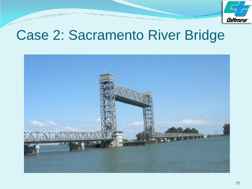
Case 2: Sacramento River Bridge
19
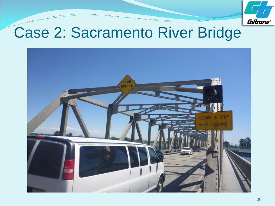
Case 2: Sacramento River Bridge
20
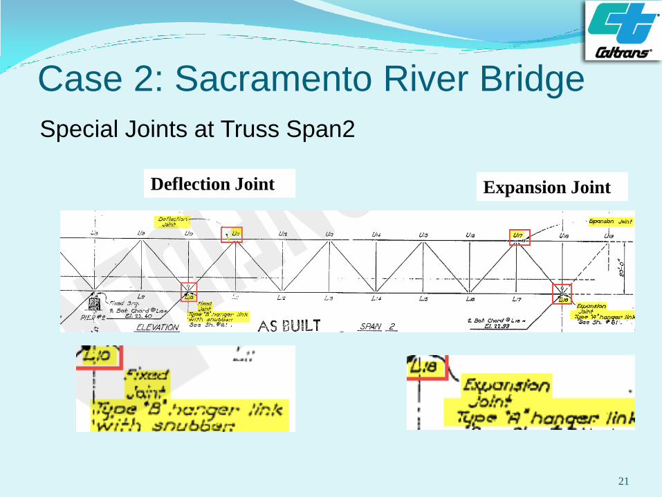
Case 2: Sacramento River Bridge
Special Joints at Truss Span2
21
Expansion Joint Deflection Joint
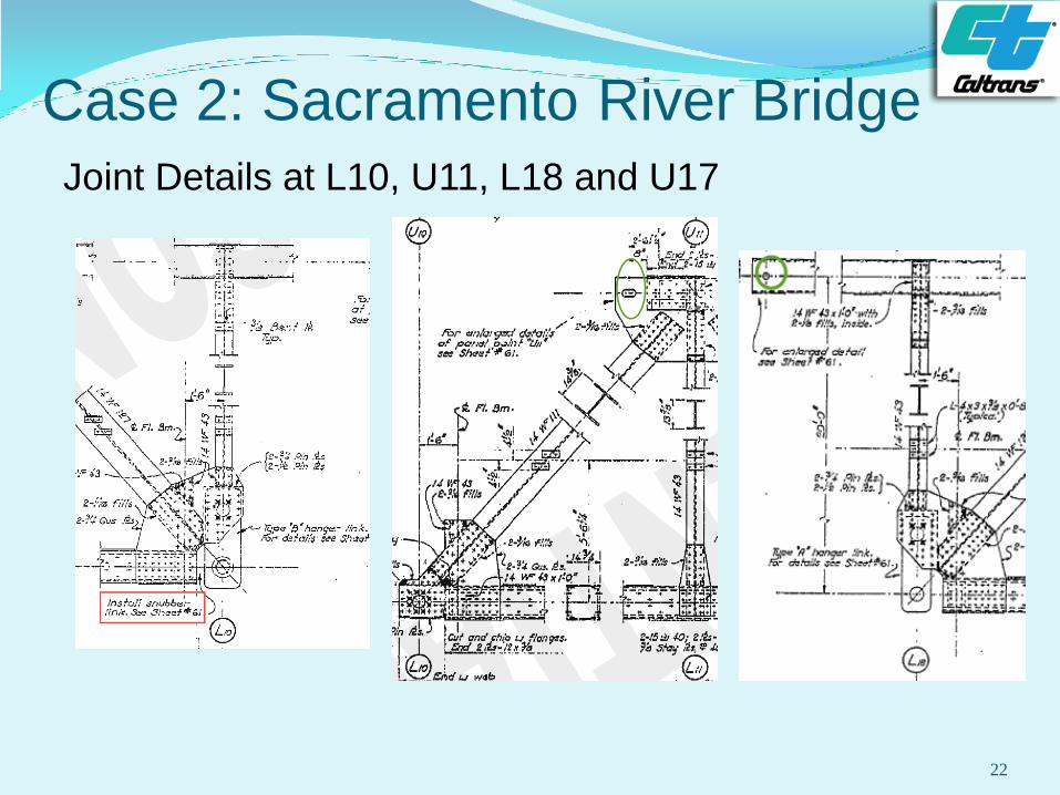
Case 2: Sacramento River Bridge
Joint Details at L10, U11, L18 and U17
22
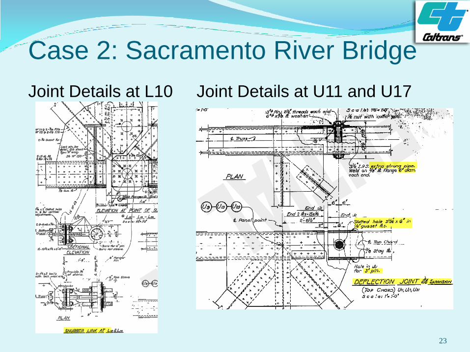
Case 2: Sacramento River Bridge
Joint Details at L10 Joint Details at U11 and U17
23
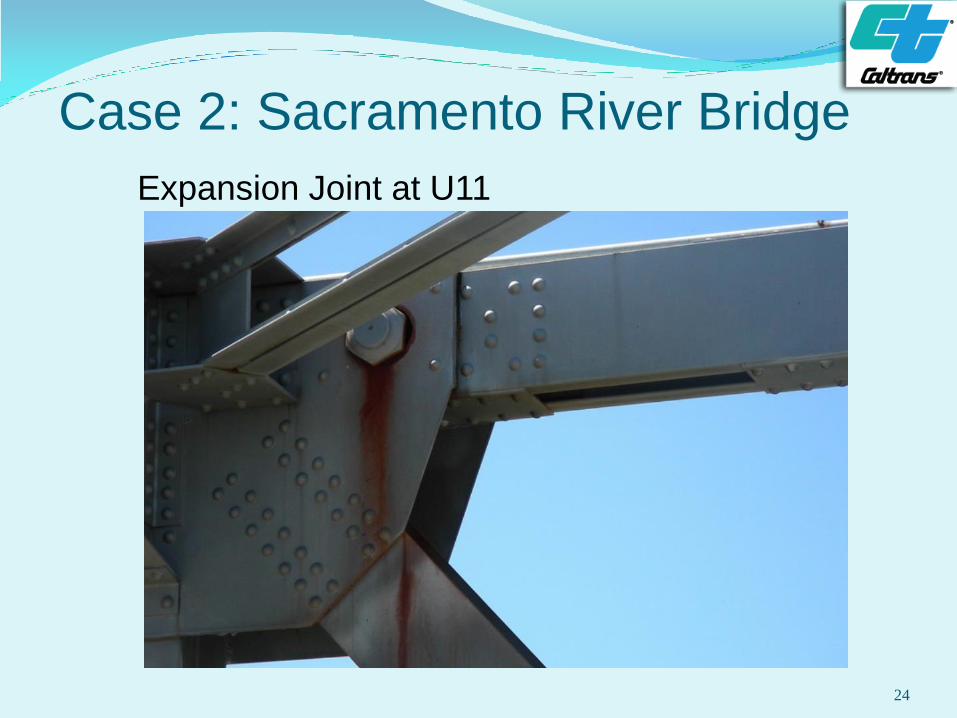
Case 2: Sacramento River Bridge
Expansion Joint at U11
24
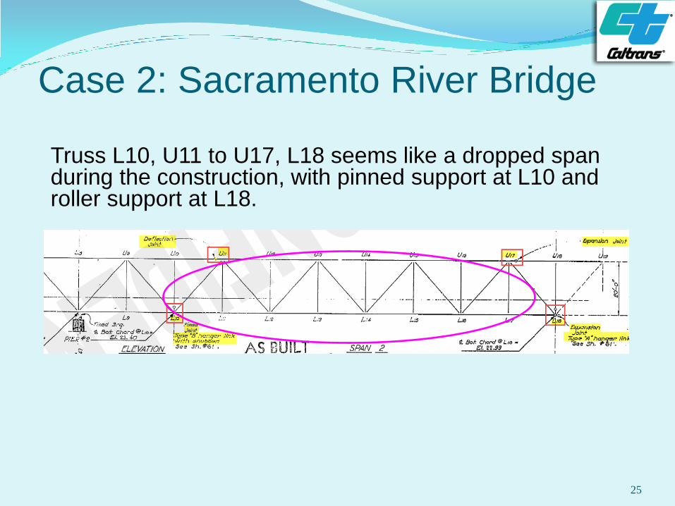
Case 2: Sacramento River Bridge
Truss L10, U11 to U17, L18 seems like a dropped span during the construction, with pinned support at L10 and roller support at L18.
25
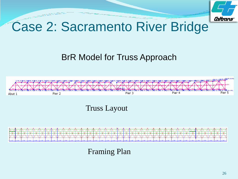
Case 2: Sacramento River Bridge
BrR Model for Truss Approach
26
Framing Plan
Truss Layout
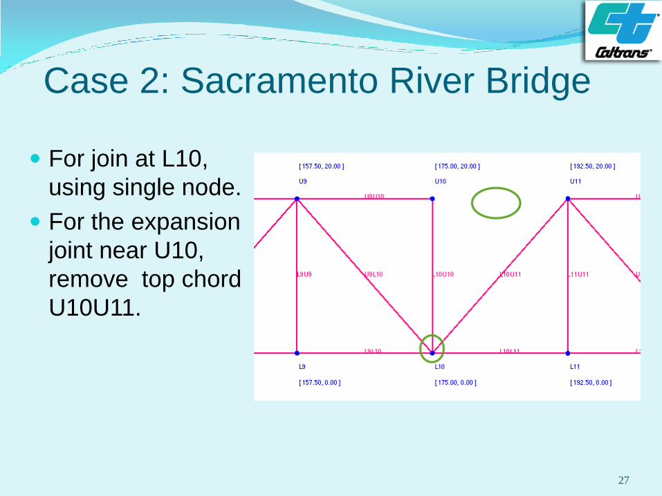
Case 2: Sacramento River Bridge
For join at L10,
using single node.
For the expansion
joint near U10,
remove top chord
U10U11.
27
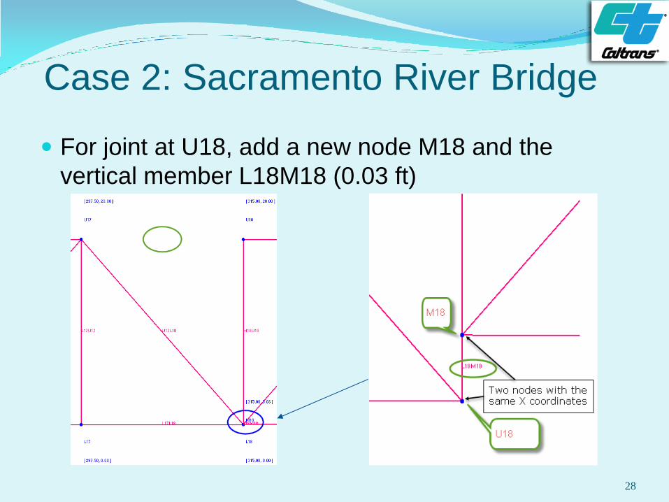
Case 2: Sacramento River Bridge
For joint at U18, add a new node M18 and the
vertical member L18M18 (0.03 ft)
28
Case 2: Sacramento River Bridge
The results from this BrR model were compared with
those from a detailed FEM model with CSiBridge. It
was found that the results from both models were
very close to each other.
29
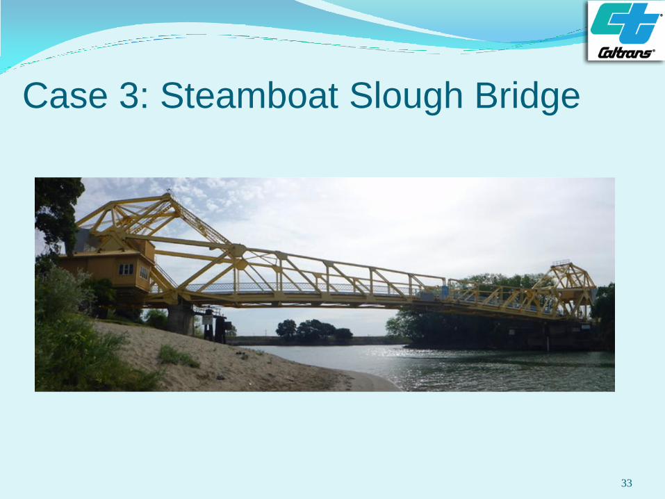
Case 3:Steamboat Slough Bridge
(Br. No. 24 0052)
Riveted double leaf Strauss bascule steel truss built
in 1924
Span lengths of 57 ft , 226 ft and 57 ft.
RC deck in Span 1 and 3, and open steel grid deck
in Span 2, all on steel stringers and floor beams
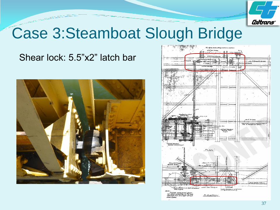
Two leaves connected with shear locks for equal live
load deflection.
30
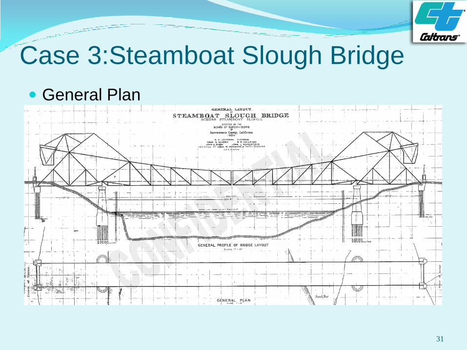
Case 3:Steamboat Slough Bridge
General Plan
31
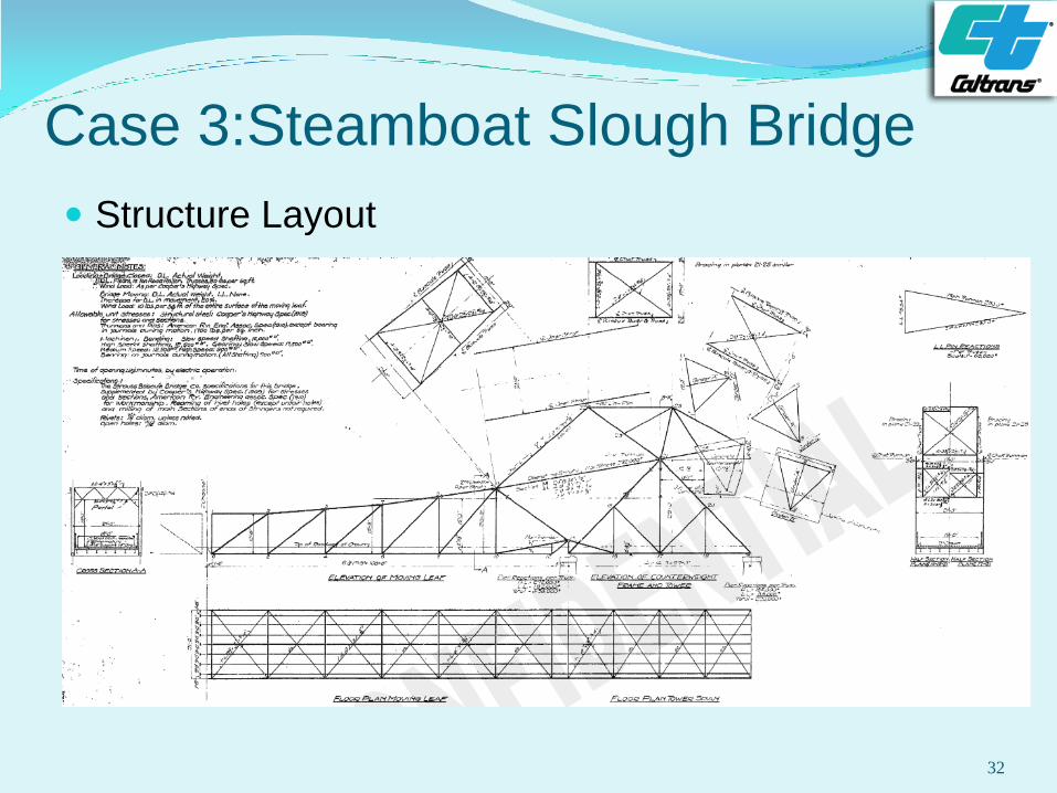
Case 3:Steamboat Slough Bridge
Structure Layout
32
Case 3: Steamboat Slough Bridge
33
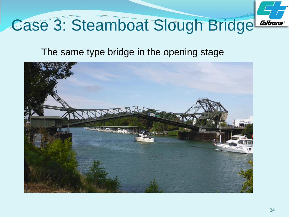
Case 3: Steamboat Slough Bridge
The same type bridge in the opening stage
34
Case 3: Steamboat Slough Bridge
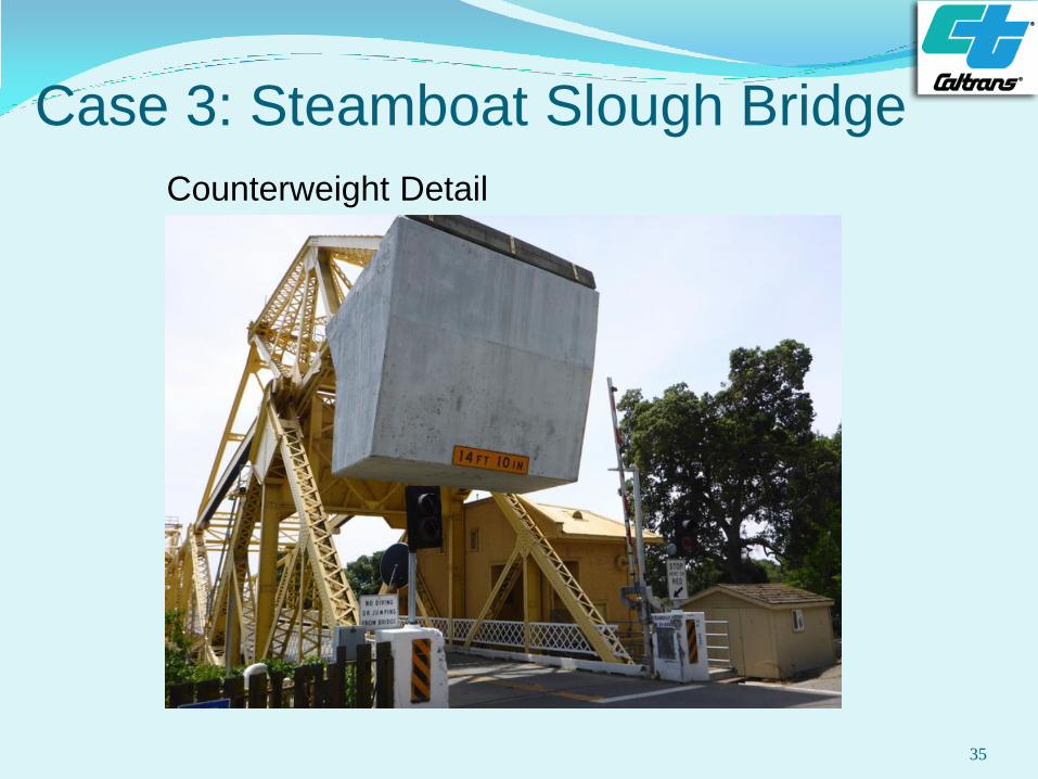
Counterweight Detail
35
Case 3: Steamboat Slough Bridge
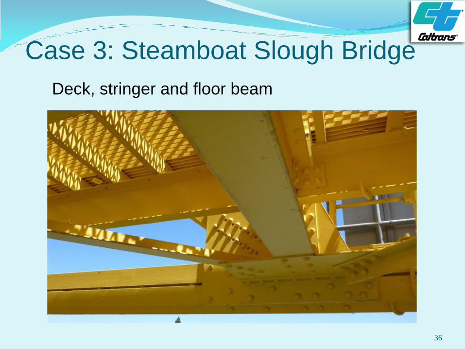
Deck, stringer and floor beam
asa
36
Case 3:Steamboat Slough Bridge
Shear lock: 5.5”x2” latch bar
37
Case 3: Steamboat Slough Bridge
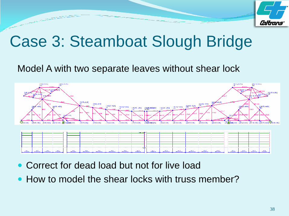
Model A with two separate leaves without shear lock
Correct for dead load but not for live load
How to model the shear locks with truss member?
38
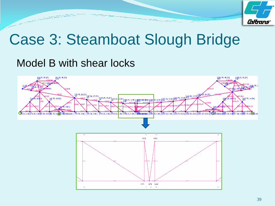
Case 3: Steamboat Slough Bridge
Model B with shear locks
39
Case 3: Steamboat Slough Bridge
In Model B,
Add an extra lower chord node between two leaves;
Create four fake truss members, two bottom chord and
two inclined, with large stiffness;
Use only one pinned support with other roller supports for
the model.
The axial force in the end vertical member (U11L11
or U12L12) is the shear force from the shear lock.
The member forces due to dead loads from Model B
are very close to those from Model A.
40
Conclusion
BrR truss analysis engines have some modeling
limitations, but with some “work around”, they can be
used for truss structures with many special details.
There are still some analysis limitations, for example,
for swing bridges, where span end bearings are
raised or jacked, at the close position. Adding
“support displacement” load function, which is
available for girder type structures, can solve this
limitation.
41

Questions?
42
![13 160 Virtual Work truss example - Powering Silicon Valley 160 Virtual Work truss... · 2 Vukazich CE 160 Truss Deflections using Method of Virtual Work [13] Real System Find truss](https://img.pdfslide.net/doc/110x75/5ac4f1987f8b9aa0518dae3e/13-160-virtual-work-truss-example-powering-silicon-160-virtual-work-truss2.jpg)