Embed Size (px)
Citation preview

Critical Design Review
Austin Anderson Suresh Ratnam Geoff Inge Eddy Scott Ethan Long Tyler Shea Gavin Montgomery Marcell Smalley Mark Onorato
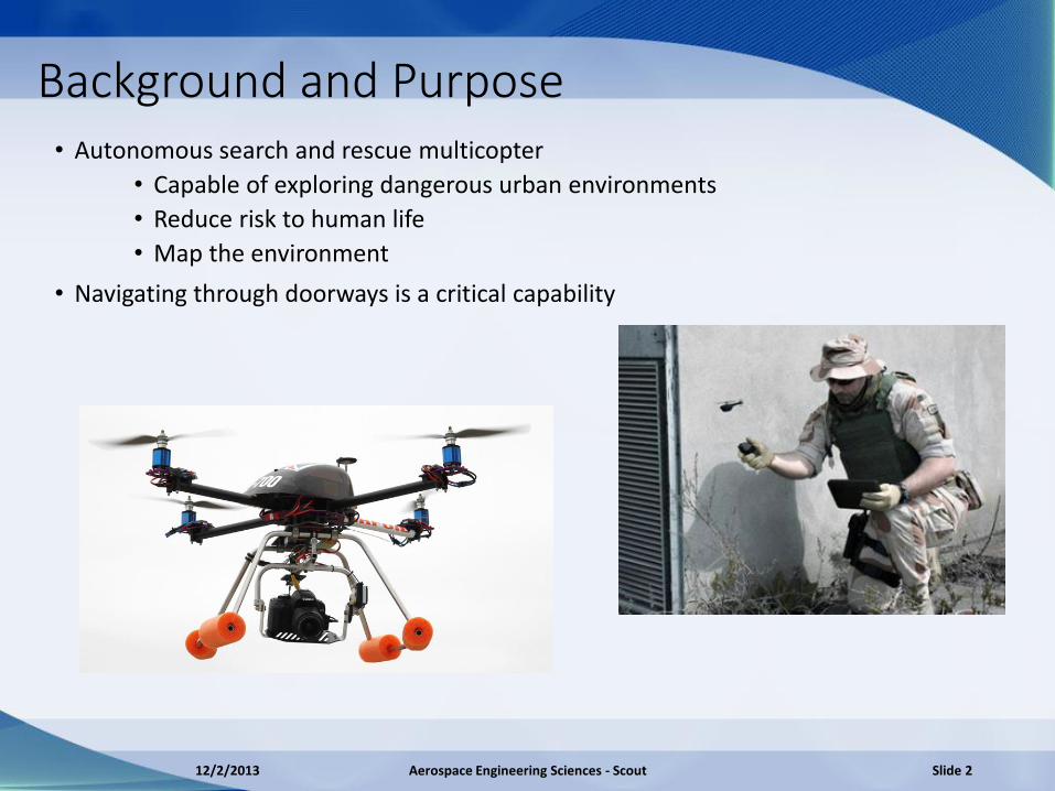
Background and Purpose • Autonomous search and rescue multicopter
• Capable of exploring dangerous urban environments
• Reduce risk to human life
• Map the environment
• Navigating through doorways is a critical capability
12/2/2013 Aerospace Engineering Sciences - Scout Slide 2
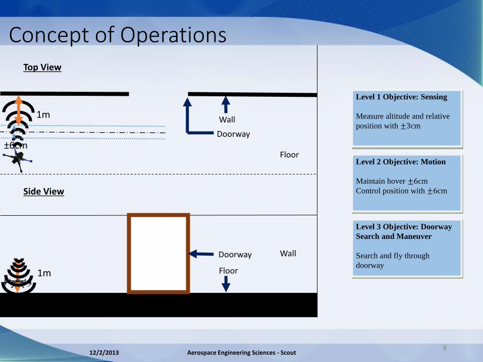
Level 1 Objective: Sensing
Measure altitude and relative
position with ±3cm
Side View
Top View
Floor
Doorway Wall
Floor
Doorway
Wall
3
Level 2 Objective: Motion
Maintain hover ±6cm
Control position with ±6cm
Level 3 Objective: Doorway
Search and Maneuver
Search and fly through
doorway
±6cm
1m
1m
Concept of Operations
12/2/2013 Aerospace Engineering Sciences - Scout
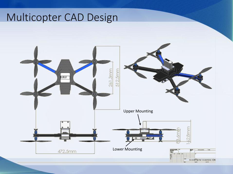
Upper Mounting
Lower Mounting
Multicopter CAD Design
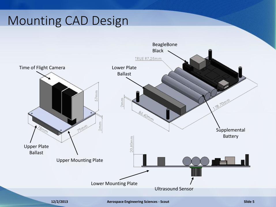
Time of Flight Camera
Upper Mounting Plate
Upper Plate Ballast
Lower Plate Ballast
Supplemental Battery
Lower Mounting Plate Ultrasound Sensor
BeagleBone Black
12/2/2013 Aerospace Engineering Sciences - Scout Slide 5
Mounting CAD Design
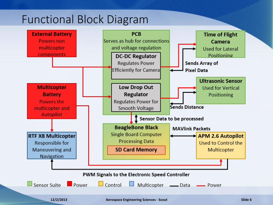
Functional Block Diagram
12/2/2013 Aerospace Engineering Sciences - Scout Slide 6
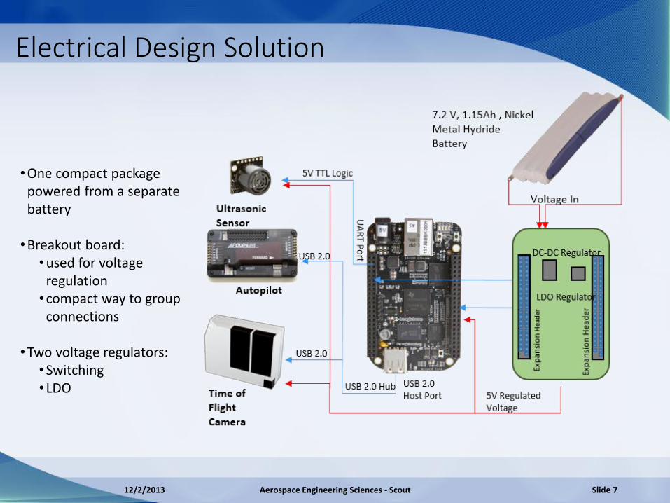
Electrical Design Solution
•One compact package powered from a separate battery
•Breakout board:
•used for voltage regulation •compact way to group
connections
•Two voltage regulators: •Switching •LDO
12/2/2013 Aerospace Engineering Sciences - Scout Slide 7

Critical Project Elements
Critical Project Element Consequence of Failure
CDE 1 Design must be capable of precision control in order to maneuver through the door
Without precision control attempting to maneuver through a doorway will result in crashes
CDE 2 Relative position measurements need to be precise to achieve precision control
If the position measurements are inaccurate the control system will be ineffective
CDE 3 Onboard power supply must enable 10 minutes of mission capabilities
Failure to meet customer requirements
CDE 4 All components must be within the payload capacity of the chosen multicopter
If the vehicle can not become airborne it will not be able to maneuver through the door
12/2/2013 Aerospace Engineering Sciences - Scout Slide 8
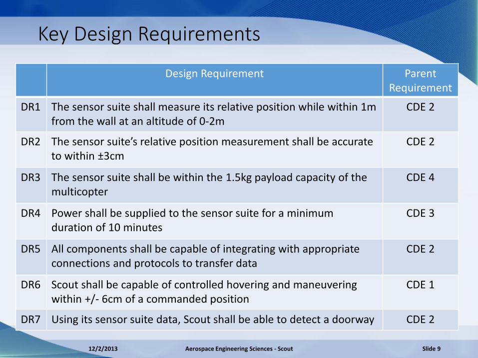
Key Design Requirements
Design Requirement Parent Requirement
DR1 The sensor suite shall measure its relative position while within 1m from the wall at an altitude of 0-2m
CDE 2
DR2 The sensor suite’s relative position measurement shall be accurate to within ±3cm
CDE 2
DR3 The sensor suite shall be within the 1.5kg payload capacity of the multicopter
CDE 4
DR4 Power shall be supplied to the sensor suite for a minimum duration of 10 minutes
CDE 3
DR5 All components shall be capable of integrating with appropriate connections and protocols to transfer data
CDE 2
DR6 Scout shall be capable of controlled hovering and maneuvering within +/- 6cm of a commanded position
CDE 1
DR7 Using its sensor suite data, Scout shall be able to detect a doorway CDE 2
12/2/2013 Aerospace Engineering Sciences - Scout Slide 9

Design Requirements
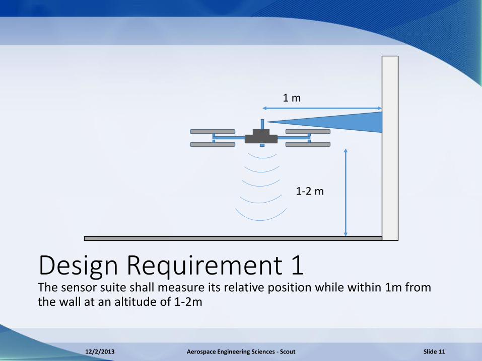
Design Requirement 1 The sensor suite shall measure its relative position while within 1m from the wall at an altitude of 1-2m
12/2/2013 Aerospace Engineering Sciences - Scout Slide 11
1-2 m
1 m
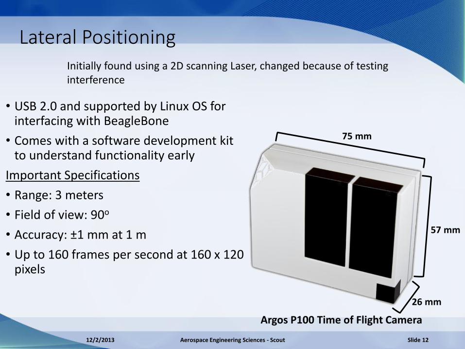
Lateral Positioning
75 mm
57 mm
26 mm
Argos P100 Time of Flight Camera
• USB 2.0 and supported by Linux OS for interfacing with BeagleBone
• Comes with a software development kit to understand functionality early
Important Specifications
• Range: 3 meters
• Field of view: 90o
• Accuracy: ±1 mm at 1 m
• Up to 160 frames per second at 160 x 120 pixels
Initially found using a 2D scanning Laser, changed because of testing interference
12/2/2013 Aerospace Engineering Sciences - Scout Slide 12
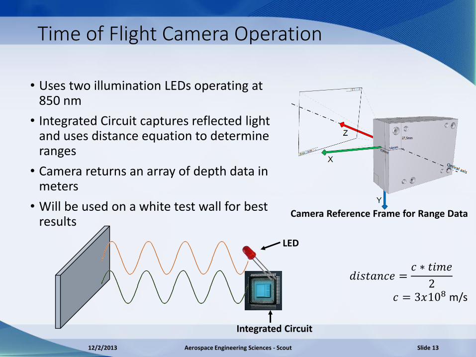
Time of Flight Camera Operation
• Uses two illumination LEDs operating at 850 nm
• Integrated Circuit captures reflected light and uses distance equation to determine ranges
• Camera returns an array of depth data in meters
• Will be used on a white test wall for best results
Camera Reference Frame for Range Data
Integrated Circuit
LED
𝑑𝑖𝑠𝑡𝑎𝑛𝑐𝑒 =𝑐 ∗ 𝑡𝑖𝑚𝑒
2
𝑐 = 3𝑥108 m/s
12/2/2013 Aerospace Engineering Sciences - Scout Slide 13
Time of Flight Simulation
12/2/2013 Aerospace Engineering Sciences - Scout Slide 14

Finding Wall at Startup
12/2/2013 Aerospace Engineering Sciences - Scout Slide 15
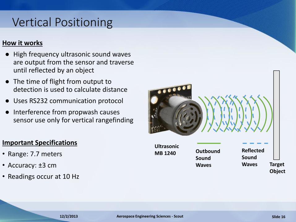
Vertical Positioning
How it works
● High frequency ultrasonic sound waves are output from the sensor and traverse until reflected by an object
● The time of flight from output to detection is used to calculate distance
● Uses RS232 communication protocol
● Interference from propwash causes sensor use only for vertical rangefinding
Important Specifications
• Range: 7.7 meters
• Accuracy: ±3 cm
• Readings occur at 10 Hz
Outbound Sound Waves
Reflected Sound Waves Target
Object
Ultrasonic MB 1240
12/2/2013 Aerospace Engineering Sciences - Scout Slide 16
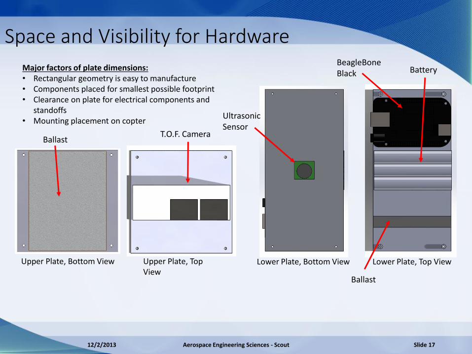
Space and Visibility for Hardware
Upper Plate, Top View
Upper Plate, Bottom View Lower Plate, Bottom View Lower Plate, Top View
Major factors of plate dimensions: • Rectangular geometry is easy to manufacture • Components placed for smallest possible footprint • Clearance on plate for electrical components and
standoffs • Mounting placement on copter
12/2/2013 Aerospace Engineering Sciences - Scout Slide 17
Ballast
Ballast
T.O.F. Camera
Ultrasonic Sensor
BeagleBone Black Battery

Space and Visibility for Hardware
Visibility Cone of Camera Diagram
Argos Camera Visibility Considerations: • Lateral Visibility
• 90o maximum field of view gained by clearance over props
• Vertical Visibility • 35% vertical field of view
obstructed by propeller
Ultrasound Field of View • Central placement on lower
plate provides unobstructed view
12/2/2013 Aerospace Engineering Sciences - Scout Slide 18

Design Requirement 2 The sensor suite relative position measurement shall be accurate to within ±3cm
12/2/2013 Aerospace Engineering Sciences - Scout Slide 19
+3 cm -3 cm
Measured Distance
Wall/Ground
Sensor
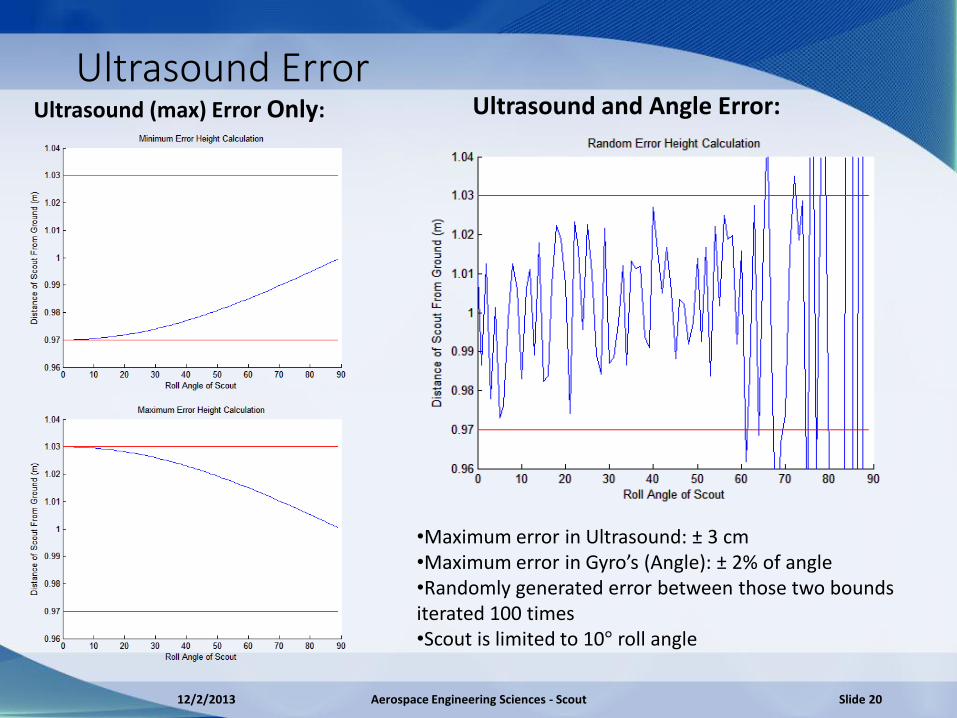
Ultrasound Error Ultrasound and Angle Error: Ultrasound (max) Error Only:
•Maximum error in Ultrasound: ± 3 cm •Maximum error in Gyro’s (Angle): ± 2% of angle •Randomly generated error between those two bounds iterated 100 times •Scout is limited to 10° roll angle
12/2/2013 Aerospace Engineering Sciences - Scout Slide 20

Camera Error
• Error never exceeds limit on white wall • Error doesn’t exceed limit until 2.7 meters on Gray wall • Take closest point of range data for distance to wall
•Works up to 45° Yaw from perpendicular •Average data from pixels around the closest point to increase accuracy
Camera Range Data For: 1m from wall, 20° Yaw
12/2/2013 Aerospace Engineering Sciences - Scout Slide 21

Design Requirement 3 The sensor suite shall be within the 1.5kg payload capacity of the multicopter
12/2/2013 Aerospace Engineering Sciences - Scout Slide 22

Negligible Disturbance of CG
z
z
z
y
y
y
x x x ballast
•Noting symmetry Standoffs don’t contribute X and Z components •Z locations of lower arrangement negotiated with zero cross moments req. Ballast added for simplicity (39.7 g of Aluminum) • Y component dictated lower standoffs (both standoffs have L = 39.8 mm). Ballast added to retain reasonable relative standoff lengths (113.7 g of Aluminum)
12/2/2013 Aerospace Engineering Sciences - Scout Slide 23
dm
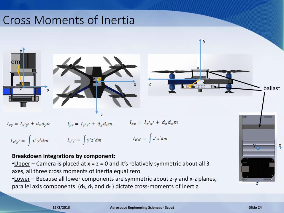
Cross Moments of Inertia
z
z
y x z
y
x
y
x z
z
x y
Breakdown integrations by component: •Upper – Camera is placed at x = z = 0 and it’s relatively symmetric about all 3 axes, all three cross moments of inertia equal zero •Lower – Because all lower components are symmetric about z-y and x-z planes, parallel axis components (dx, dy and dz ) dictate cross-moments of inertia
ballast
12/2/2013 Aerospace Engineering Sciences - Scout Slide 24
dm
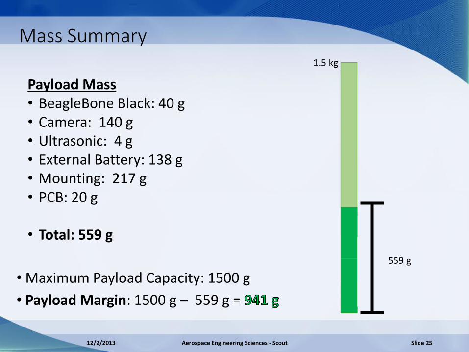
Mass Summary
• Maximum Payload Capacity: 1500 g
• Payload Margin: 1500 g – 559 g =
1.5 kg
559 g
Payload Mass • BeagleBone Black: 40 g • Camera: 140 g • Ultrasonic: 4 g • External Battery: 138 g • Mounting: 217 g • PCB: 20 g
• Total: 559 g
12/2/2013 Aerospace Engineering Sciences - Scout Slide 25
Design Requirement 4 Power shall be supplied to the sensor suite for a minimum duration of 10 minutes
12/2/2013 Aerospace Engineering Sciences - Scout Slide 26
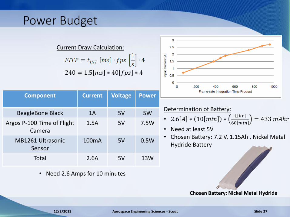
Power Budget
240 = 1.5 𝑚𝑠 ∗ 40 𝑓𝑝𝑠 ∗ 4
Component Current Voltage Power
BeagleBone Black 1A 5V 5W
Argos P-100 Time of Flight Camera
1.5A 5V 7.5W
MB1261 Ultrasonic Sensor
100mA 5V 0.5W
Total 2.6A 5V 13W
• Need 2.6 Amps for 10 minutes
Determination of Battery:
• 2.6 𝐴 ∗ 10 𝑚𝑖𝑛 ∗1 ℎ𝑟
60 𝑚𝑖𝑛= 433 𝑚𝐴ℎ𝑟
• Need at least 5V • Chosen Battery: 7.2 V, 1.15Ah , Nickel Metal
Hydride Battery
Chosen Battery: Nickel Metal Hydride
Current Draw Calculation:
12/2/2013 Aerospace Engineering Sciences - Scout Slide 27

Voltage Regulation
• Two voltage regulators
• DC-DC Switching Regulator for camera (more efficient than LDO, has noise)
• Low Dropout Regulator for BeagleBone and Ultrasonic (Smooth voltage with 0.35V dropout at 1.5A allows for increased performance)
7.2V, 1.15 Ah, Nickel Metal
Hydride Battery
Quadcoptor Battery, 11.1V,
4.2 Ah LiPo
DC-DC Switching Regulator
APM Power Module
Low Dropout Regulator
Time of Flight Camera
BeagleBone Black
Ultrasonic Sensor
APM Autopilot
Max 10V, 1A 5V
5V
Max 40V, 3A
12/2/2013 Aerospace Engineering Sciences - Scout Slide 28
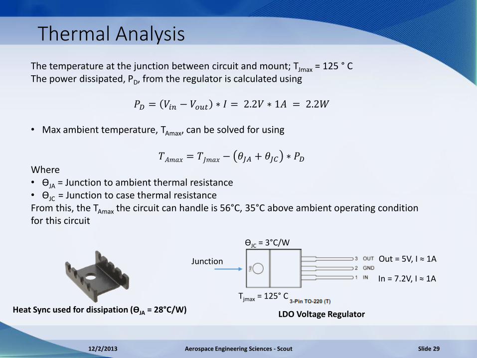
Thermal Analysis
ϴJC = 3°C/W
Out = 5V, I ≈ 1A
In = 7.2V, I ≈ 1A
Tjmax = 125° C
The temperature at the junction between circuit and mount; TJmax = 125 ° C The power dissipated, PD, from the regulator is calculated using
𝑃𝐷 = 𝑉𝑖𝑛 − 𝑉𝑜𝑢𝑡 ∗ 𝐼 = 2.2𝑉 ∗ 1𝐴 = 2.2𝑊
• Max ambient temperature, TAmax, can be solved for using
𝑇𝐴𝑚𝑎𝑥 = 𝑇𝐽𝑚𝑎𝑥 − 𝜃𝐽𝐴 + 𝜃𝐽𝐶 ∗ 𝑃𝐷
Where • ϴJA = Junction to ambient thermal resistance
• ϴJC = Junction to case thermal resistance From this, the TAmax the circuit can handle is 56°C, 35°C above ambient operating condition for this circuit
Junction
Heat Sync used for dissipation (ϴJA = 28°C/W)
LDO Voltage Regulator
12/2/2013 Aerospace Engineering Sciences - Scout Slide 29

Design Requirement 5 All components shall be capable of integrating with appropriate connections and protocols to transfer data
12/2/2013 Aerospace Engineering Sciences - Scout Slide 30

Data Handling
Argos P100 Camera: • Get 3D coordinates from the current frame • 3D Coordinates are organized as iterations of x, y, z float values
120 ∗ 160[𝑝𝑖𝑥𝑒𝑙𝑠/𝑓𝑟𝑎𝑚] ∗ 3[𝑎𝑑𝑑𝑟𝑒𝑠𝑠𝑒𝑠/𝑝𝑖𝑥𝑒𝑙] ∗ 32[𝑏𝑖𝑡𝑠/𝑎𝑑𝑑𝑟𝑒𝑠𝑠] ∗ 40[𝑓𝑝𝑠]
= 73.7 Mbits/s
Ultrasonic Sensor: • Serial data sent is 9600 baud, with 8 data bits, no parity, and one stop bit • Can configure the UART ports to operate at same rate with same configuration • Sends 40 bytes every second, ASCII ‘R’, followed by three numbers
APM 2.6 Autopilot • USB 2.0 data sent at a baud rate of 115200 • Will be plugged into the second port of the USB hub • Sends a MAVLink packet with a maximum of 256 bytes at 100 Hz
12/2/2013 Aerospace Engineering Sciences - Scout Slide 31
Camera Data Output Format

Data Handling
12/2/2013 Aerospace Engineering Sciences - Scout Slide 32
Design Requirement 6 Scout shall be capable of controlled hovering and maneuvering within ±6cm of a commanded position
12/2/2013 Aerospace Engineering Sciences - Scout Slide 33
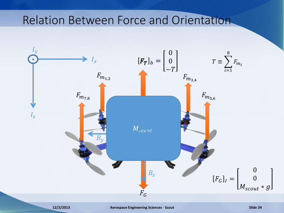
Relation Between Force and Orientation
𝐹𝑚1,2 𝐹𝑚3,4
𝐹𝑚5,6 𝐹𝑚7,8
𝐹𝐺
𝐼𝑥
𝐼𝑧
𝐼𝑦
𝐹𝑇 𝑏 =00−𝑇
𝑇 ≡ 𝐹𝑚𝑖
8
𝑖=1
𝐹𝐺 𝐼 =00
𝑀𝑠𝑐𝑜𝑢𝑡 ∗ 𝑔
𝐵𝑦
𝐵𝑧
𝑀𝑠𝑐𝑜𝑢𝑡
𝐹𝑇
12/2/2013 Aerospace Engineering Sciences - Scout Slide 34
𝐵𝑥

−𝜃
Relation Between Force and Orientation
𝐹𝐺
𝐼𝑥
𝐼𝑧
𝐼𝑦
𝐹𝑇 𝐼𝑥
𝐹𝑇
−𝐼 𝑧
−𝐼𝑧
𝐹𝐺
𝐹𝑠𝑐𝑜𝑢𝑡 𝐼 = 𝑅𝑏/𝑖 𝐹𝑇 𝑏 + 𝐹𝐺 𝐼
𝑅𝑏/𝑖 = 𝑅3 𝜓 𝑅2 𝜃 𝑅1 𝜙
𝜓 ≡ 𝑦𝑎𝑤 𝑎𝑛𝑔𝑙𝑒
𝜙 ≡ 𝑟𝑜𝑙𝑙 𝑎𝑛𝑔𝑙𝑒 𝜃 ≡ 𝑝𝑖𝑡𝑐ℎ 𝑎𝑛𝑔𝑙𝑒
𝐹𝑥𝐹𝑦𝐹𝑧
=
−𝑇(𝑠𝑖𝑛𝜙𝑠𝑖𝑛𝜓 + 𝑐𝑜𝑠𝜙𝑐𝑜𝑠𝜓𝑠𝑖𝑛𝜃)𝑇(𝑐𝑜𝑠𝜓𝑠𝑖𝑛𝜙 − 𝑐𝑜𝑠𝜃𝑠𝑖𝑛𝜓𝑠𝑖𝑛𝜃)
𝑔 ∗ 𝑀𝑠𝑐𝑜𝑢𝑡 − 𝑇𝑐𝑜𝑠𝜙𝑐𝑜𝑠𝜃
Small Angle Linearization: 𝒄𝒐𝒔𝜽 ≅ 𝟏, 𝒔𝒊𝒏𝜽 ≅ 𝜽, 𝜽𝟐 ≅ 𝟎 𝐹𝑥𝐹𝑦𝐹𝑧
≅−𝑇𝜃𝑇𝜙
𝑔 ∗ 𝑀𝑠𝑐𝑜𝑢𝑡 − 𝑇= 𝑀𝑠𝑐𝑜𝑢𝑡
𝑥 𝑦 𝑧 𝐼
12/2/2013 Aerospace Engineering Sciences - Scout Slide 35

Altitude Control Block Diagram
𝑍𝑑 +
-
𝐸 𝐶(𝑠) 𝑀𝑠𝑐𝑜𝑢𝑡
+ +
𝑔 ∗ 𝑀𝑠𝑐𝑜𝑢𝑡
−𝑇𝑑𝑒𝑠𝑖𝑟𝑒𝑑
+
𝑍 𝑑𝑒𝑠𝑖𝑟𝑒𝑑 −𝑻 + 𝒈 ∗𝑴𝒔𝒄𝒐𝒖𝒕 1
𝑀𝑠𝑐𝑜𝑢𝑡𝑠2
-
𝑍𝑑 + 𝐸 𝐶(𝑠)
𝑍 𝑑𝑒𝑠𝑖𝑟𝑒𝑑
-
1
𝑠2
𝑍𝑎𝑐𝑡
𝑍𝑎𝑐𝑡
𝑍𝑎𝑐𝑡
−𝑇𝑑𝑒𝑠𝑖𝑟𝑒𝑑 = 𝑀𝑠𝑐𝑜𝑢𝑡𝑍 𝑑 −𝑔 ∗ 𝑀𝑠𝑐𝑜𝑢𝑡 𝑍 = 𝑍𝑑 1
𝑠2= −𝑇 + 𝑔 ∗ 𝑀𝑆𝑐𝑜𝑢𝑡
1
𝑠2𝑀𝑠𝑐𝑜𝑢𝑡
12/2/2013 Aerospace Engineering Sciences - Scout Slide 36
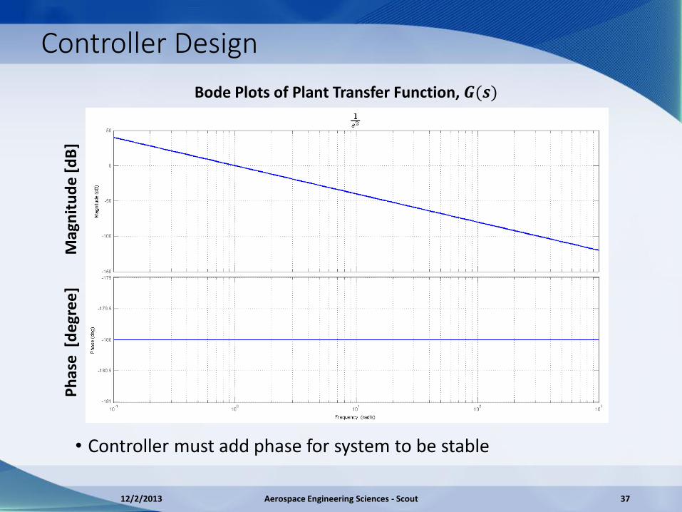
Controller Design
Bode Plots of Plant Transfer Function, 𝑮(𝒔)
• Controller must add phase for system to be stable
Mag
nit
ud
e [d
B]
Ph
ase
[d
egr
ee
]
12/2/2013 Aerospace Engineering Sciences - Scout 37
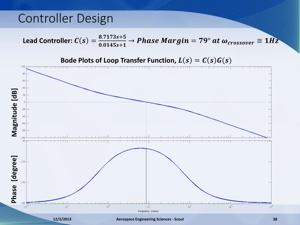
Controller Design
Bode Plots of Loop Transfer Function, 𝑳 𝒔 = 𝑪 𝒔 𝑮(𝒔)
Lead Controller: 𝑪 𝒔 =𝟖.𝟕𝟏𝟕𝟑𝒔+𝟓
𝟎.𝟎𝟏𝟒𝟓𝒔+𝟏→ 𝑷𝒉𝒂𝒔𝒆 𝑴𝒂𝒓𝒈𝒊𝒏 = 𝟕𝟗° 𝒂𝒕 𝝎𝒄𝒓𝒐𝒔𝒔𝒐𝒗𝒆𝒓 ≅ 𝟏𝑯𝒛
Mag
nit
ud
e [
dB
] P
has
e [
de
gre
e]
12/2/2013 Aerospace Engineering Sciences - Scout 38

Controller Performance-No Command Saturation • Commanded angles and
thrust passed into full non-linear force equations
• Violation of small angle
linearization yields poor controller performance
• Solution: Add limits to what angles and thrust can be requested
12/2/2013 Aerospace Engineering Sciences - Scout Slide 39

Controller Performance- Saturation
12/2/2013 Aerospace Engineering Sciences - Scout Slide 40
𝜃𝑚𝑎𝑥 = 10° 𝑇𝑚𝑎𝑥 = 2𝑚𝑔
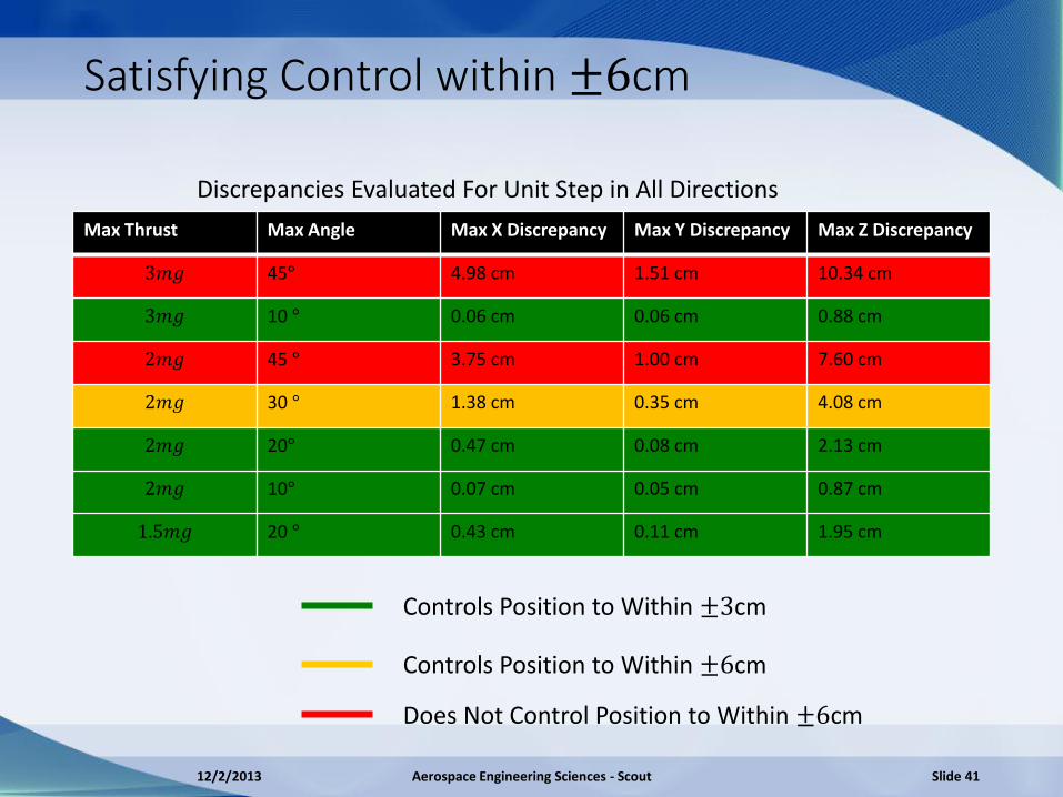
Satisfying Control within ±6cm
Max Thrust Max Angle Max X Discrepancy Max Y Discrepancy Max Z Discrepancy
3𝑚𝑔 45° 4.98 cm 1.51 cm 10.34 cm
3𝑚𝑔 10 ° 0.06 cm 0.06 cm 0.88 cm
2𝑚𝑔 45 ° 3.75 cm 1.00 cm 7.60 cm
2𝑚𝑔 30 ° 1.38 cm 0.35 cm 4.08 cm
2𝑚𝑔 20° 0.47 cm 0.08 cm 2.13 cm
2𝑚𝑔 10° 0.07 cm 0.05 cm 0.87 cm
1.5𝑚𝑔 20 ° 0.43 cm 0.11 cm 1.95 cm
Discrepancies Evaluated For Unit Step in All Directions
Controls Position to Within ±3cm
Controls Position to Within ±6cm
Does Not Control Position to Within ±6cm
12/2/2013 Aerospace Engineering Sciences - Scout Slide 41
Design Requirement 7 Scout shall be able to detect and maneuver through the doorway while adhering to the positioning and control
12/2/2013 Aerospace Engineering Sciences - Scout Slide 42

Camera Data Door Searching
12/2/2013 Aerospace Engineering Sciences - Scout Slide 43
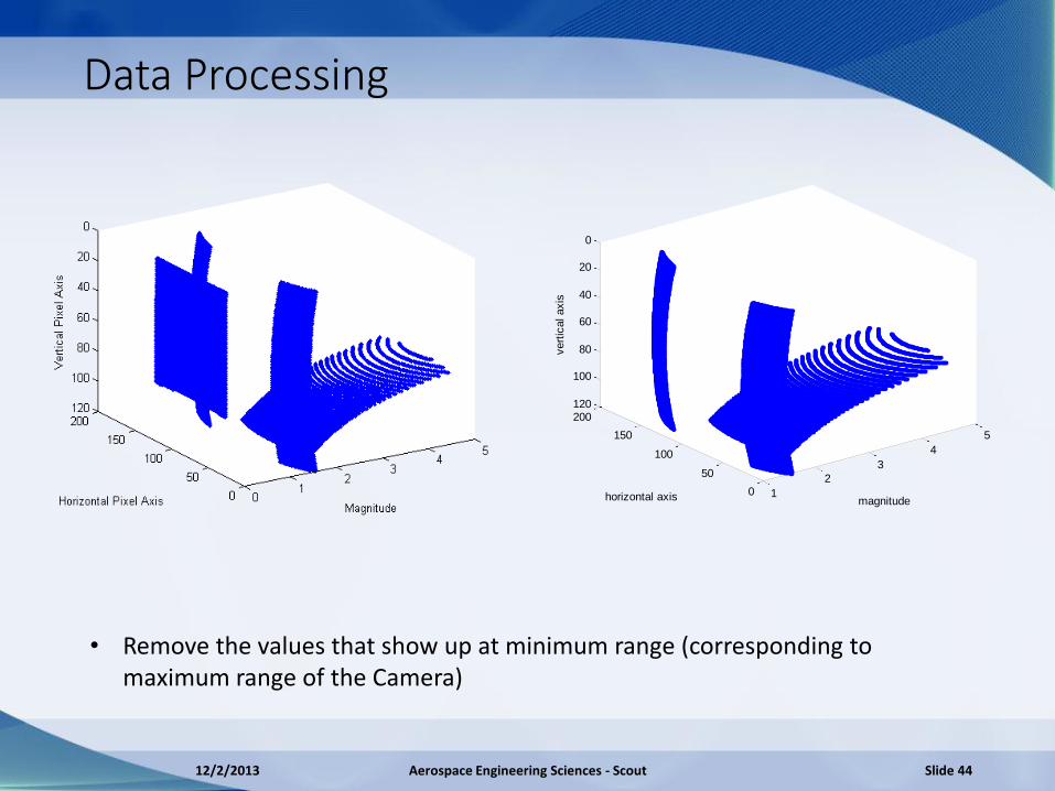
Data Processing
1
2
3
4
5
0
50
100
150
200
0
20
40
60
80
100
120
magnitudehorizontal axis
vert
ical axis
• Remove the values that show up at minimum range (corresponding to maximum range of the Camera)
12/2/2013 Aerospace Engineering Sciences - Scout Slide 44

Risk Analysis

Risk Summary
All important risks listed for each subsystem Probability and impact of occurrence values specified (From 1 to 5) Risk matrix created of Impact vs. Probability
12/2/2013 Aerospace Engineering Sciences - Scout Slide 46
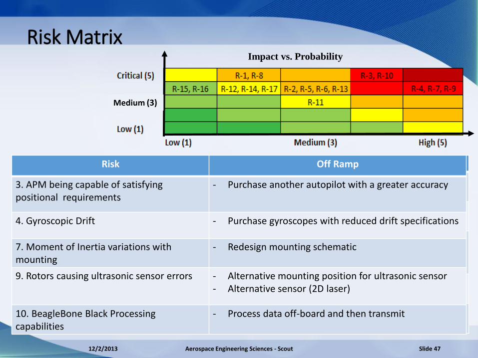
Risk Matrix
Risk Mitigation Techniques
3. APM being capable of satisfying positional requirements
- Decrease speed - Verify that the calibration is optimal
4. Gyroscopic Drift - Determine orientation from camera data - Test gyroscopic drift over time to counteract
7. Moment of Inertia variations with mounting
- Design mounting to produce minimal changes in moment of inertia
- Ballast Scout to reduce mounting effects
9. Rotors causing ultrasonic sensor errors
- Create shielding for the ultrasonic sensor - Propeller low frequency filtering
10. BeagleBone Black Processing capabilities
- Decrease the number of points analyzed from camera data
Impact vs. Probability
Risk Off Ramp
3. APM being capable of satisfying positional requirements
- Purchase another autopilot with a greater accuracy
4. Gyroscopic Drift - Purchase gyroscopes with reduced drift specifications
7. Moment of Inertia variations with mounting
- Redesign mounting schematic
9. Rotors causing ultrasonic sensor errors - Alternative mounting position for ultrasonic sensor - Alternative sensor (2D laser)
10. BeagleBone Black Processing capabilities
- Process data off-board and then transmit
12/2/2013 Aerospace Engineering Sciences - Scout Slide 47
Medium (3)

Verification and Validation

Testing Schedule
12/2/2013 Aerospace Engineering Sciences - Scout Slide 49
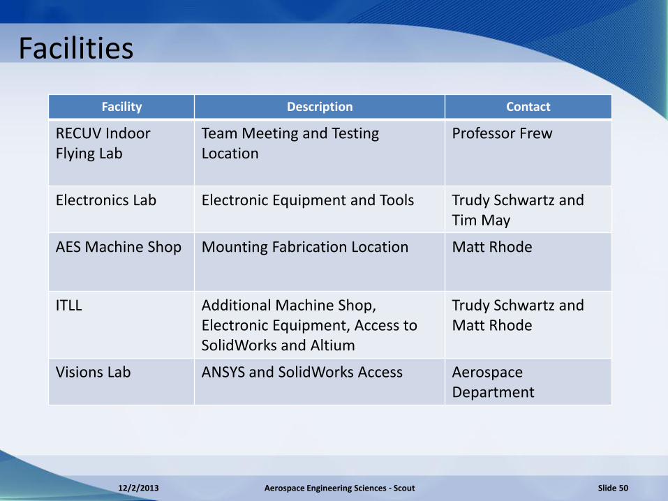
Facilities
Facility Description Contact
RECUV Indoor Flying Lab
Team Meeting and Testing Location
Professor Frew
Electronics Lab Electronic Equipment and Tools Trudy Schwartz and Tim May
AES Machine Shop Mounting Fabrication Location Matt Rhode
ITLL Additional Machine Shop, Electronic Equipment, Access to SolidWorks and Altium
Trudy Schwartz and Matt Rhode
Visions Lab ANSYS and SolidWorks Access Aerospace Department
12/2/2013 Aerospace Engineering Sciences - Scout Slide 50
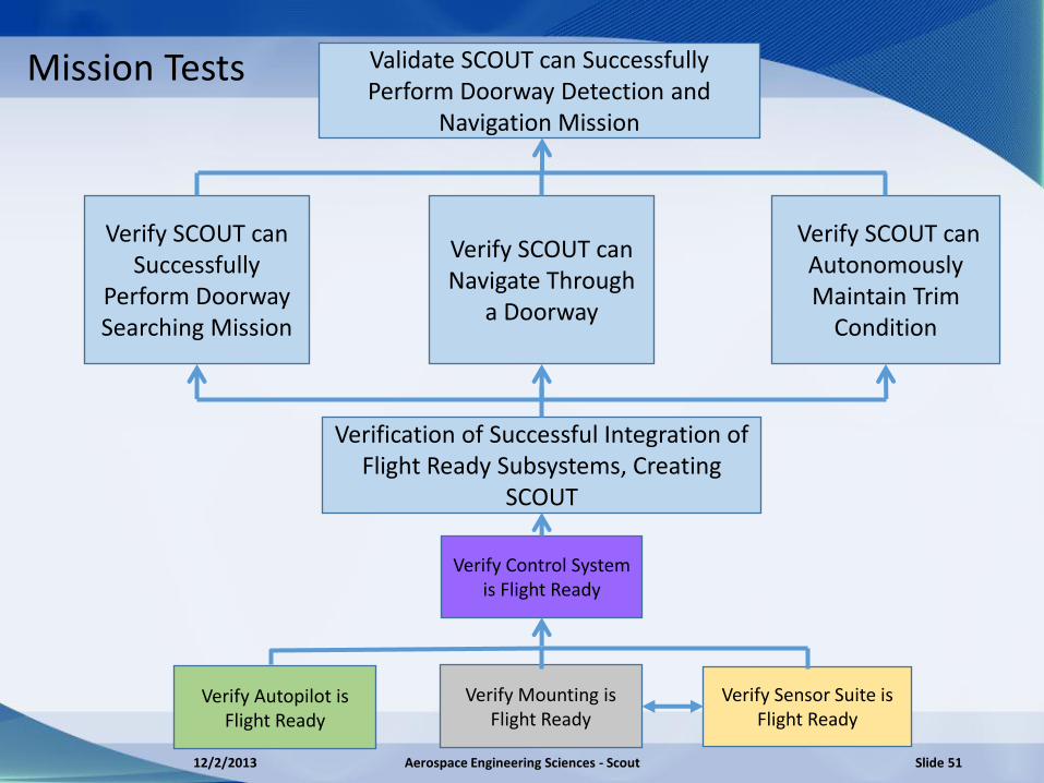
Validate SCOUT can Successfully Perform Doorway Detection and
Navigation Mission
Verify SCOUT can Navigate Through
a Doorway
Verify SCOUT can Autonomously Maintain Trim
Condition
Mission Tests
Verify Autopilot is Flight Ready
Verification of Successful Integration of Flight Ready Subsystems, Creating
SCOUT
Verify Sensor Suite is Flight Ready
Verify Control System is Flight Ready
Verify Mounting is Flight Ready
Verify SCOUT can Successfully
Perform Doorway Searching Mission
12/2/2013 Aerospace Engineering Sciences - Scout Slide 51
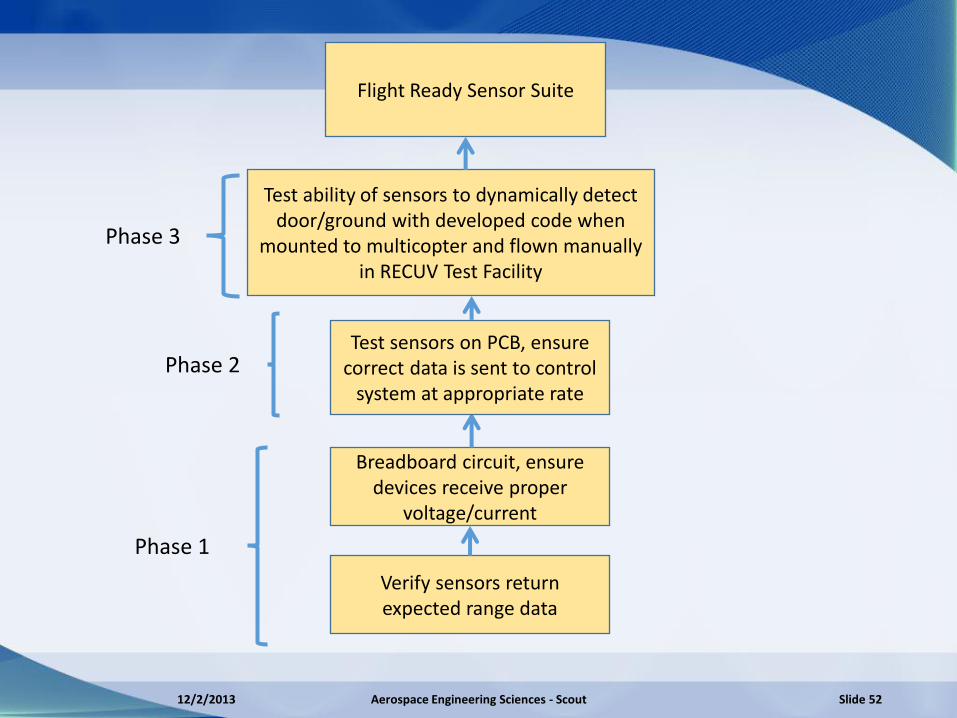
Test ability of sensors to dynamically detect door/ground with developed code when
mounted to multicopter and flown manually in RECUV Test Facility
Breadboard circuit, ensure devices receive proper
voltage/current
Flight Ready Sensor Suite
Verify sensors return expected range data
Test sensors on PCB, ensure correct data is sent to control
system at appropriate rate
Phase 1
Phase 2
Phase 3
12/2/2013 Aerospace Engineering Sciences - Scout Slide 52

RC Controller
Ultrasonic Sensor FOV
SCOUT with Sensors
T.O.F Camera FOV
VICON PC
Safety Netting
Wall Door
Compare Vicon measurements and sensor measurements
12/2/2013 Aerospace Engineering Sciences - Scout Slide 53
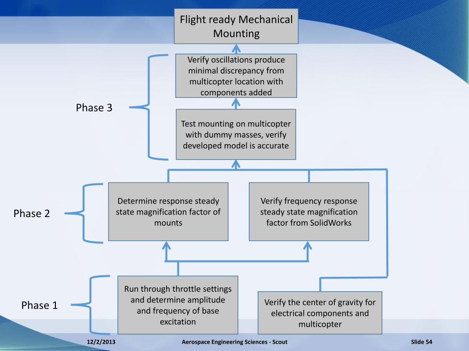
Flight ready Mechanical Mounting
Run through throttle settings and determine amplitude
and frequency of base excitation
Verify frequency response steady state magnification
factor from SolidWorks
Determine response steady state magnification factor of
mounts
Test mounting on multicopter with dummy masses, verify
developed model is accurate
Verify oscillations produce minimal discrepancy from multicopter location with
components added
Phase 1
Phase 3
Phase 2
Verify the center of gravity for electrical components and
multicopter
12/2/2013 Aerospace Engineering Sciences - Scout Slide 54
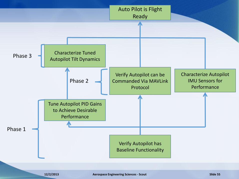
Auto Pilot is Flight Ready
Characterize Tuned Autopilot Tilt Dynamics
Verify Autopilot can be Commanded Via MAVLink
Protocol
Tune Autopilot PID Gains to Achieve Desirable
Performance
Characterize Autopilot IMU Sensors for
Performance
Verify Autopilot has Baseline Functionality
Phase 1
Phase 2
Phase 3
12/2/2013 Aerospace Engineering Sciences - Scout Slide 55
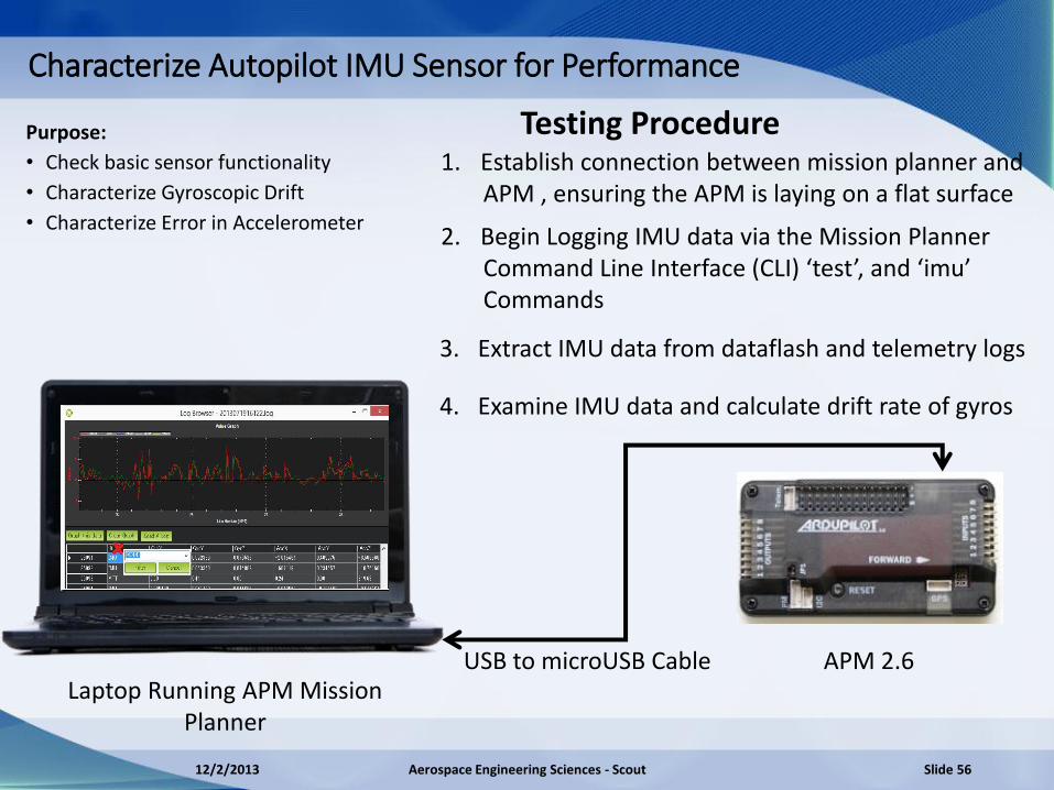
Purpose:
• Check basic sensor functionality
• Characterize Gyroscopic Drift
• Characterize Error in Accelerometer
Laptop Running APM Mission Planner
APM 2.6
Characterize Autopilot IMU Sensor for Performance
USB to microUSB Cable
Testing Procedure 1. Establish connection between mission planner and APM , ensuring the APM is laying on a flat surface
2. Begin Logging IMU data via the Mission Planner Command Line Interface (CLI) ‘test’, and ‘imu’ Commands
3. Extract IMU data from dataflash and telemetry logs
4. Examine IMU data and calculate drift rate of gyros
12/2/2013 Aerospace Engineering Sciences - Scout Slide 56
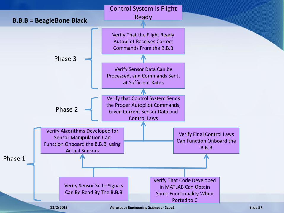
Verify Sensor Data Can be Processed, and Commands Sent,
at Sufficient Rates
Control System Is Flight Ready
Verify That the Flight Ready Autopilot Receives Correct Commands From the B.B.B
Verify that Control System Sends the Proper Autopilot Commands,
Given Current Sensor Data and Control Laws
Verify Algorithms Developed for Sensor Manipulation Can
Function Onboard the B.B.B, using Actual Sensors
B.B.B = BeagleBone Black
Verify Final Control Laws Can Function Onboard the
B.B.B
Verify Sensor Suite Signals Can Be Read By The B.B.B
Verify That Code Developed in MATLAB Can Obtain
Same Functionality When Ported to C
Phase 1
Phase 2
Phase 3
12/2/2013 Aerospace Engineering Sciences - Scout Slide 57

Verification and Validation
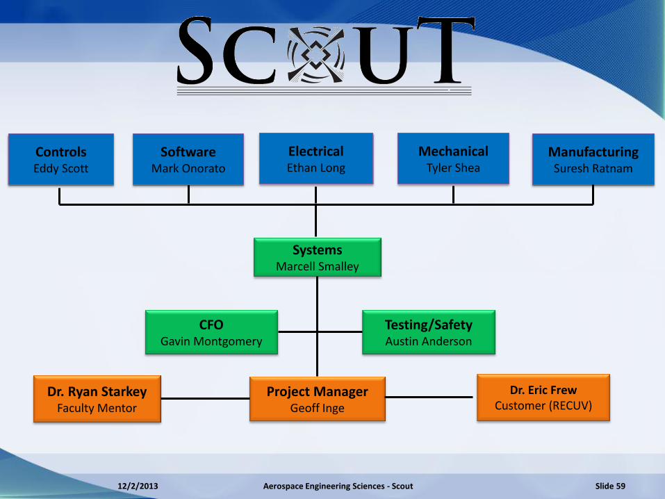
Dr. Ryan Starkey Faculty Mentor
Dr. Eric Frew Customer (RECUV)
CFO Gavin Montgomery
Testing/Safety Austin Anderson
Systems Marcell Smalley
Project Manager Geoff Inge
Software Mark Onorato
Electrical Ethan Long
Manufacturing Suresh Ratnam
Mechanical Tyler Shea
Controls Eddy Scott
12/2/2013 Aerospace Engineering Sciences - Scout Slide 59
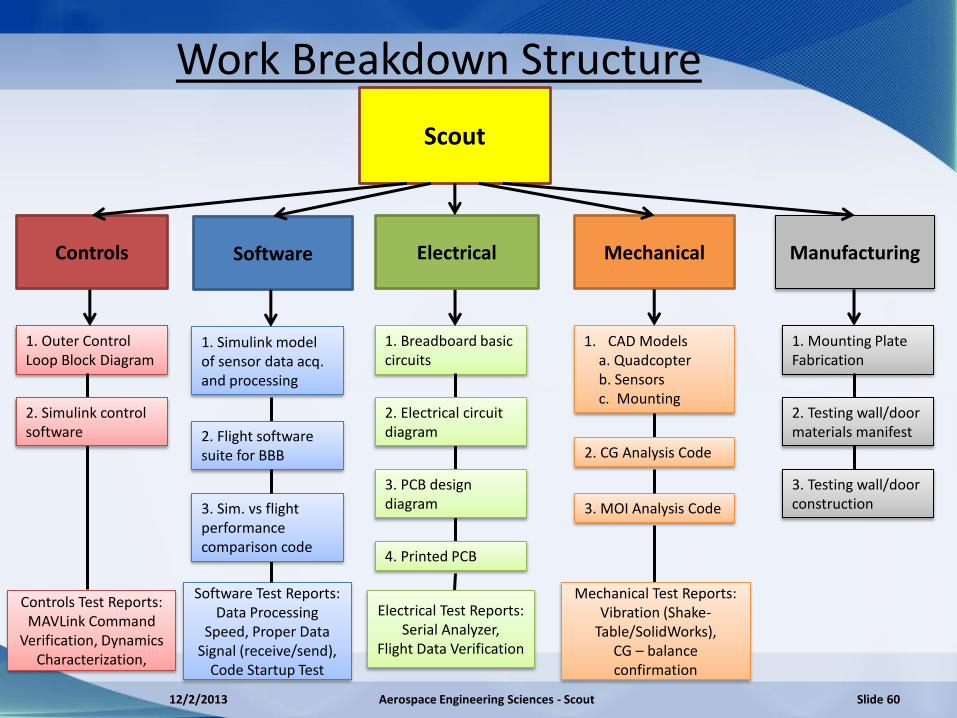
Work Breakdown Structure
Software Electrical Manufacturing Mechanical Controls
1. Outer Control Loop Block Diagram
1. Simulink model of sensor data acq. and processing
1. Breadboard basic circuits
1. CAD Models a. Quadcopter b. Sensors c. Mounting
1. Mounting Plate Fabrication
Controls Test Reports: MAVLink Command
Verification, Dynamics Characterization,
Software Test Reports: Data Processing
Speed, Proper Data Signal (receive/send),
Code Startup Test
Electrical Test Reports: Serial Analyzer,
Flight Data Verification
Mechanical Test Reports: Vibration (Shake-
Table/SolidWorks), CG – balance confirmation
2. Flight software suite for BBB
3. Sim. vs flight performance comparison code
Scout
2. Simulink control software
2. Electrical circuit diagram
3. PCB design diagram
4. Printed PCB
2. CG Analysis Code
3. MOI Analysis Code
2. Testing wall/door materials manifest
3. Testing wall/door construction
12/2/2013 Aerospace Engineering Sciences - Scout Slide 60
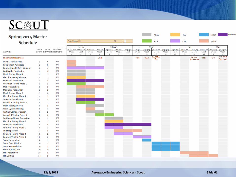
12/2/2013 Aerospace Engineering Sciences - Scout Slide 61

Cost Breakdown- Main Budget
Item Cost
Single Board Computer $45
Time of Flight Camera $1140
Ultrasonic Sensor $35
Electronics $100
Mounting $100
Software/Controls $50
Testing/Safety $300
Total $1770
Margin $3230
12/2/2013 Aerospace Engineering Sciences - Scout Slide 62

Cost Breakdown- Vehicle Platform
Product Cost
RTF X8 Quadcopter $929.00
APM 2.6 Autopilot (Included)
Replacement Kit $114.99
2 Additional Batteries $102.99
Telemetry Kit $99.99
Total $1246.97
Margin $1753.03
12/2/2013 Aerospace Engineering Sciences - Scout Slide 63

1Hee Jin Sohn; Byung-Kook Kim, "A Robust Localization Algorithm for Mobile Robots with Laser Range Finders," Robotics and Automation, 2005. ICRA 2005. Proceedings of the 2005 IEEE International Conference on Robotics , pp.3545,3550, 18-22 April 2005
2Steux, B.; El Hamzaoui, O., "tinySLAM: A SLAM algorithm in less than 200 lines C-language program," Control Automation Robotics & Vision (ICARCV), 2010 11th International Conference on , pp.1975,1979, 7-10 Dec. 2010
3Bachrach, A.; de Winter, A.; Ruijie He; Hemann, G.; Prentice, S.; Roy, N., "RANGE - robust autonomous navigation in GPS-denied environments," Robotics and Automation (ICRA), 2010 IEEE International Conference on , pp.1096,1097, 3-7 May 2010
4“Laser Scanners, TiM3xx / TiM31x / Indoor / Short Range” , SICK Sensor Intelligence., https://www.mysick.com/ecat.aspx?go=FinderSearch&Cat=Gus&At=Fa&Cult=English&FamilyID=344&Category=Produktfinder&Selections=53789 [Cited 10 October 2013]
5“Mid range distance sensors, Dx35 / DS35 / IO-Link” , SICK Sensor Intelligence., https://www.mysick.com/ecat.aspx?go=FinderSearch&Cat=Gus&At=Fa&Cult=English&FamilyID=402&Category=Produktfinder&Selections=75114 [Cited 10 October 2013]
6“AT: Samsung Li-Ion 18650 Cylindrical 7.4V 2800mAh Flat Top Rechargeable Battery w/ PCM Protection” , All-Battery.com, Total Power Solutions, http://www.all-battery.com/SamsungLi-Ion18650_7.4V_2800mAhwithPCM-31444.aspx [Cited 13 October 2013]
7“BeagleBone Black” , beagleboard.org, http://beagleboard.org/Products/BeagleBone%20Black [Cited 7 October 2013]
8“URG-04LX-UG01 Product Information”, Hokuyo Automatic Co., http://www.hokuyo-aut.jp/02sensor/07scanner/download/products/urg-04lx-ug01/, [September 23, 2013]
9“MB1043 HRLV-MaxSonar®-EZ4? Product”, MaxBotix, http://www.maxbotix.com/Ultrasonic_Sensors/MB1043.htm, [September 27, 2013]
10“3DR RTF X8,” 3D Robotics UAV Technology, http://store.3drobotics.com/products/apm-3dr-x8-rtf, [cited 22 September 2013]
11“APM 2.6 Set (external compass),” 3D Robotics UAV Technology, http://store.3drobotics.com/products/apm-2-6-kit-1, [cited 25 September 2013]
12“Laser Grid GS1,” GhostStop Ghost Hunting Equipment, http://www.ghoststop.com/Laser-Grid-GS1-p/laser-lasergrid-gs1.htm, [cited 10 October 2013]
13“Notch Filters,” Thor Labs, http://www.thorlabs.us/NewGroupPage9.cfm?ObjectGroup_ID=3880&, [cited 10 October 2013]
14“X8 Motor Out Test,” YouTube.com, http://www.youtube.com/watch?v=cdS6Cy5aOvk, [cited 4 October 2013]
12/2/2013 Aerospace Engineering Sciences - Scout 64
References

Questions?
12/2/2013 Aerospace Engineering Sciences - Scout Slide 65

Appendix
12/2/2013 Aerospace Engineering Sciences - Scout Slide 66
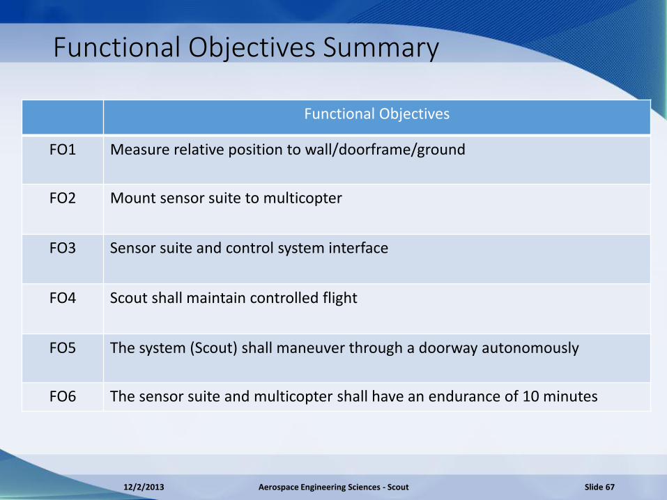
Functional Objectives Summary
Functional Objectives
FO1 Measure relative position to wall/doorframe/ground
FO2 Mount sensor suite to multicopter
FO3 Sensor suite and control system interface
FO4 Scout shall maintain controlled flight
FO5 The system (Scout) shall maneuver through a doorway autonomously
FO6 The sensor suite and multicopter shall have an endurance of 10 minutes
12/2/2013 Aerospace Engineering Sciences - Scout Slide 67

Timing
APM (100 Hz)
Camera (40 Hz)
Ultrasound (10 Hz)
.1s
New Camera Data New Sonar Data
•APM expects inputs at 100 Hz •While new data is not produced, the old input commands will be sent
•1 or 2 cycles with the same input to APM
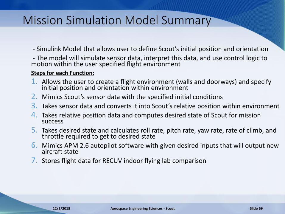
Mission Simulation Model Summary
- Simulink Model that allows user to define Scout’s initial position and orientation
- The model will simulate sensor data, interpret this data, and use control logic to motion within the user specified flight environment Steps for each Function:
1. Allows the user to create a flight environment (walls and doorways) and specify initial position and orientation within environment
2. Mimics Scout’s sensor data with the specified initial conditions
3. Takes sensor data and converts it into Scout’s relative position within environment
4. Takes relative position data and computes desired state of Scout for mission success
5. Takes desired state and calculates roll rate, pitch rate, yaw rate, rate of climb, and throttle required to get to desired state
6. Mimics APM 2.6 autopilot software with given desired inputs that will output new aircraft state
7. Stores flight data for RECUV indoor flying lab comparison
12/2/2013 Aerospace Engineering Sciences - Scout Slide 69

Equations of Motion
𝐹𝑠𝑐𝑜𝑢𝑡 𝐼 = 𝑅𝑏/𝑖 𝐹𝑇 𝑏 + 𝐹𝐺 𝐼
𝐹𝑥𝐹𝑦𝐹𝑧
=
−𝑇(𝑠𝑖𝑛𝜙𝑠𝑖𝑛𝜓 + 𝑐𝑜𝑠𝜙𝑐𝑜𝑠𝜓𝑠𝑖𝑛𝜃)𝑇(𝑐𝑜𝑠𝜓𝑠𝑖𝑛𝜙 − 𝑐𝑜𝑠𝜃𝑠𝑖𝑛𝜓𝑠𝑖𝑛𝜃)
𝑔 ∗ 𝑀𝑠𝑐𝑜𝑢𝑡 − 𝑇𝑐𝑜𝑠𝜙𝑐𝑜𝑠𝜃
Small Angle Linearization: 𝒄𝒐𝒔𝜽 ≅ 𝜽, 𝒔𝒊𝒏𝜽 ≅ 𝜽, 𝜽𝟐 ≅ 𝟎
𝐹𝑥𝐹𝑦𝐹𝑧
≅−𝑇𝜃𝑇𝜙
𝑔 ∗ 𝑀𝑠𝑐𝑜𝑢𝑡 − 𝑇= 𝑀𝑠𝑐𝑜𝑢𝑡
𝑥 𝑦 𝑧 𝐼
𝑥𝑦𝑧 𝐼
=1
𝑠2𝑀𝑠𝑐𝑜𝑢𝑡
−𝑇𝜃𝑇𝜙
𝑔 ∗ 𝑀𝑠𝑐𝑜𝑢𝑡 − 𝑇
𝐿𝑎𝑝𝑙𝑎𝑐𝑒 𝑇𝑟𝑎𝑛𝑠𝑓𝑜𝑟𝑚:
Can now calculate 𝑻,𝝓, 𝒂𝒏𝒅 𝜽 given a desired inertial acceleration
Using 𝑻,𝝓, 𝒂𝒏𝒅 𝜽; 𝐭𝐡𝐞 𝐫𝐞𝐬𝐮𝐥𝐭𝐢𝐧𝐠 𝐜𝐡𝐚𝐧𝐠𝐞 𝐢𝐧 𝐢𝐧𝐞𝐫𝐭𝐢𝐚𝐥 𝐩𝐨𝐬𝐢𝐭𝐢𝐨𝐧 𝐜𝐚𝐧 𝐛𝐞 𝐟𝐨𝐮𝐧𝐝
12/2/2013 Aerospace Engineering Sciences - Scout Slide 70

𝐷𝑟𝑎𝑤 𝐸𝑛𝑣
-
𝑃𝑑 𝑆𝑒𝑛𝑠𝑜𝑟𝑠 𝑃𝑟𝑜𝑐𝑒𝑠𝑠𝑖𝑛𝑔
+
𝑃𝑎𝑐𝑡𝑢𝑎𝑙
𝑃 =
𝑥𝑦𝑧𝜙𝜃𝜓
Draw Env Draws the room with Scout at a given state Sensors Mimics camera & ultrasonic readings (with errors) Processing Carries out logic algorithm for Scout Plant Model Simplified Non-linear dynamics of quad
𝑃𝑙𝑎𝑛𝑡 𝑀𝑜𝑑𝑒𝑙
User input IC
𝑜𝑛𝑒 𝑡𝑖𝑚𝑒
𝑃𝑒
12/2/2013 Aerospace Engineering Sciences - Scout Slide 71
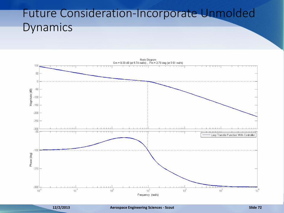
Future Consideration-Incorporate Unmolded Dynamics
12/2/2013 Aerospace Engineering Sciences - Scout Slide 72
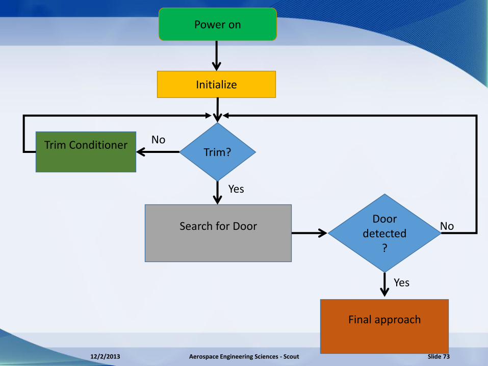
Search for Door
Initialize
Door detected
?
Final approach
Trim Conditioner
Yes
No
Power on
Trim?
Yes
No
12/2/2013 Aerospace Engineering Sciences - Scout Slide 73

Check signals from camera, ultrasonic & APM (Gyros)
Set flag (error indicator)
Abort mission & shutdown
Altitude Control
Log error data
Bad
Good
Wall Detect
Perpendicular Control
Initialize
12/2/2013 Aerospace Engineering Sciences - Scout Slide 74

Is height measurement
1m ±6 𝑐𝑚
Continue
Set Z desired to be 1m for the controller
No
Yes
Yes
Altitude Control
12/2/2013 Aerospace Engineering Sciences - Scout Slide 75
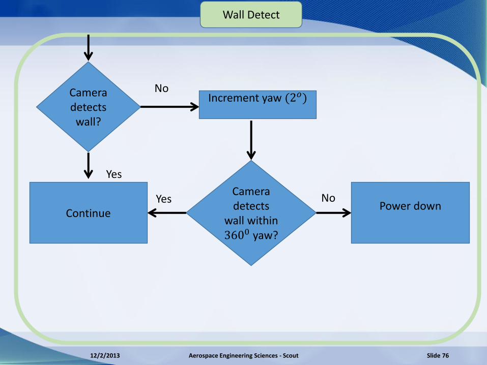
Camera detects wall?
Increment yaw (2𝑜)
Continue
No
Yes No Camera detects
wall within 3600 yaw?
Yes
Power down
Wall Detect
12/2/2013 Aerospace Engineering Sciences - Scout Slide 76
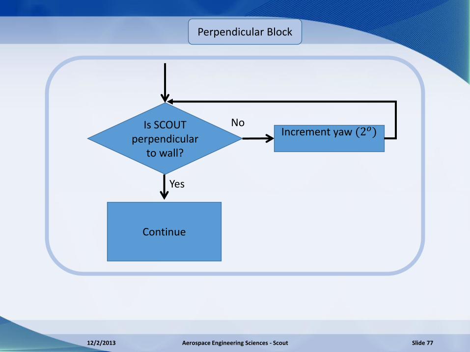
Is SCOUT perpendicular
to wall?
Increment yaw (2𝑜)
Continue
No
Yes
Perpendicular Block
12/2/2013 Aerospace Engineering Sciences - Scout Slide 77
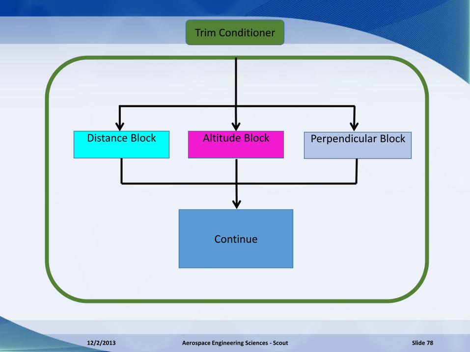
Trim Conditioner
Altitude Block
Distance Block
Perpendicular Block
Continue
12/2/2013 Aerospace Engineering Sciences - Scout Slide 78

Distance Block
Is SCOUT 1m ±
6𝑐𝑚 from the wall?
Set x desired to
be 1m for controller
Continue
No
Yes
12/2/2013 Aerospace Engineering Sciences - Scout Slide 79

Search for Door
Move to the right while perpendicular to wall
(Increment y desired by X m)
Stop marker
detected?
Continue moving until discontinuity in camera
data is detected
Change direction and increment y desired by X m
Yes
Continue
12/2/2013 Aerospace Engineering Sciences - Scout Slide 80

Final Approach
Position center to the doorframe
Set x desired to be 3m
Power down
12/2/2013 Aerospace Engineering Sciences - Scout Slide 81
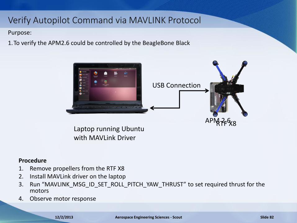
Verify Autopilot Command via MAVLINK Protocol Purpose:
1.To verify the APM2.6 could be controlled by the BeagleBone Black
Laptop running Ubuntu with MAVLink Driver
USB Connection
APM 2.6
Procedure 1. Remove propellers from the RTF X8 2. Install MAVLink driver on the laptop 3. Run “MAVLINK_MSG_ID_SET_ROLL_PITCH_YAW_THRUST” to set required thrust for the
motors 4. Observe motor response
RTF X8
12/2/2013 Aerospace Engineering Sciences - Scout Slide 82
Data Processing Risk
RAM: • 512MB of RAM and 2GB of eMMC flash from which you can run Ubuntu • 512 MB RAM can store 4,294,967,296 bits • Need to store approximately 73,700,000 bits/s
Processing: • Running Linux in the background makes it difficult to determine processing
time. • Code has not been generated in order to determine processing time
Off Ramps: • If fps are reduced to 10 fps number of bits to be processed decreases by 25% • Can also reduce the number of pixels processed
Gyro Drift
• Error associated with yaw angles from gyro integration.
• Possible solution is by locking onto the wall (Staying perpendicular)
• MPU-6000 Six-Axis (Gyro + Accelerometer) MEMS
• ± 2% for deviation from 25𝑜
12/2/2013 Aerospace Engineering Sciences - Scout Slide 84
Top-Level Functional Req.’s of Mounting • 1. Space and Visibility of sensors
• 1.1 Total mounting surface provides enough room for electrical components
• 1.2 Sensors placed on surfaces for maximum visibility
• 1.3 Standoffs provide clearance over multicopter’s structure (don’t interfere w/ x8 structure)
• 2. Satisfy weight budget • 2.1 Summation of masses of mounting surfaces, the standoffs and the electrical components must less than
1.5 kg
• 3. Negligible Discrepancy of C.G • 3.1 Surfaces do not disturb x-cg and z-cg components
• 3.2 Electrical component arrangements do not disturb x-cg and z-cg components
• 3.3 Standoffs do not disturb x-cg and z-cg components
• 3.4 Relative position of upper and lower configurations do not disturb y-cg component
• 4. Negligible Discrepancy of craft’s cross moments of inertia
• 4.1 Surfaces induce zero cross-sectional moments of inertia
• 4.2 Sensor placement induce zero cross-sectional moments of inertia
• 4.3 Standoff placement do not induce non-zero cross-sectional moments of inertia
• 5. Support Electrical Components
• Surface supports components without failing due to static and dynamic loading
• Standoffs support surfaces without failing
• 6. Dampen Adverse Frequencies
• Dampening device attenuates vibration frequencies imposed by multicopter’s powerplant that would damage sensors otherwise.
12/2/2013 Aerospace Engineering Sciences - Scout Slide 85
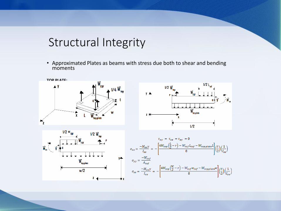
Structural Integrity
• Approximated Plates as beams with stress due both to shear and bending moments
TOP PLATE:
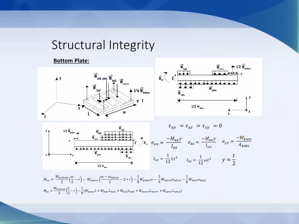
Bottom Plate:
Structural Integrity
𝐼𝑧𝑧 = 1
12𝜔𝑡3 𝑦 =
𝑡
2
𝑀𝑧𝑧 =𝑊𝑏𝑜𝑡𝑡𝑜𝑚
2
𝐿
2− 𝑟 −
1
8(𝑊𝑝𝑙𝑎𝑡𝑒𝐿 +𝑊𝑏𝑎𝑡𝑡𝐿𝑏𝑎𝑡𝑡 +𝑊𝑏𝑎𝑙𝑙𝐿𝑏𝑎𝑙𝑙 +𝑊𝑚𝑖𝑐𝑟𝑜𝐿𝑚𝑖𝑐𝑟𝑜 +𝑊𝑢𝑙𝑡𝑟𝑎𝐿𝑢𝑙𝑡𝑟𝑎)
𝑀𝑥𝑥 = 𝑊𝑏𝑜𝑡𝑡𝑜𝑚
2
𝜔
2− 𝑟 − 𝑊𝑚𝑖𝑐𝑟𝑜
𝜔 − 𝜔𝑚𝑖𝑐𝑟𝑜
2− 2 ∗ 𝑟 −
1
8𝑊𝑝𝑙𝑎𝑡𝑒𝜔 −
1
4𝑊𝑢𝑙𝑡𝑟𝑎𝜔𝑢𝑙𝑡𝑟𝑎 −
1
8𝑊𝑏𝑎𝑡𝑡𝜔𝑏𝑎𝑡𝑡
𝐼𝑥𝑥 = 1
12𝐿𝑡3
𝜏𝑥𝑦 = 𝜏𝑥𝑧 = 𝜏𝑧𝑦 = 0
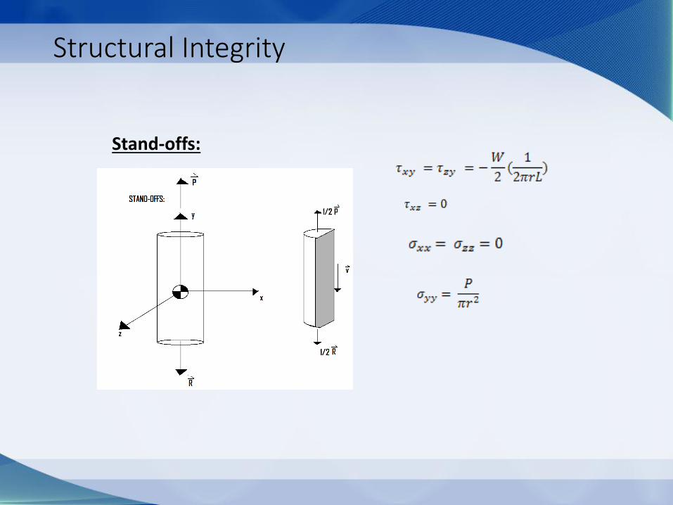
Structural Integrity
Stand-offs:

Minimum Factor of Safety
• 3D Mohr’s Circle
• Minimum Factor of safety was found to be associated with lower plate FS =128.68
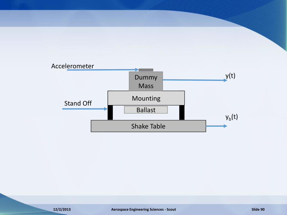
Stand Off Mounting
Shake Table
Dummy Mass
Ballast
Accelerometer
y(t)
yb(t)
12/2/2013 Aerospace Engineering Sciences - Scout Slide 90
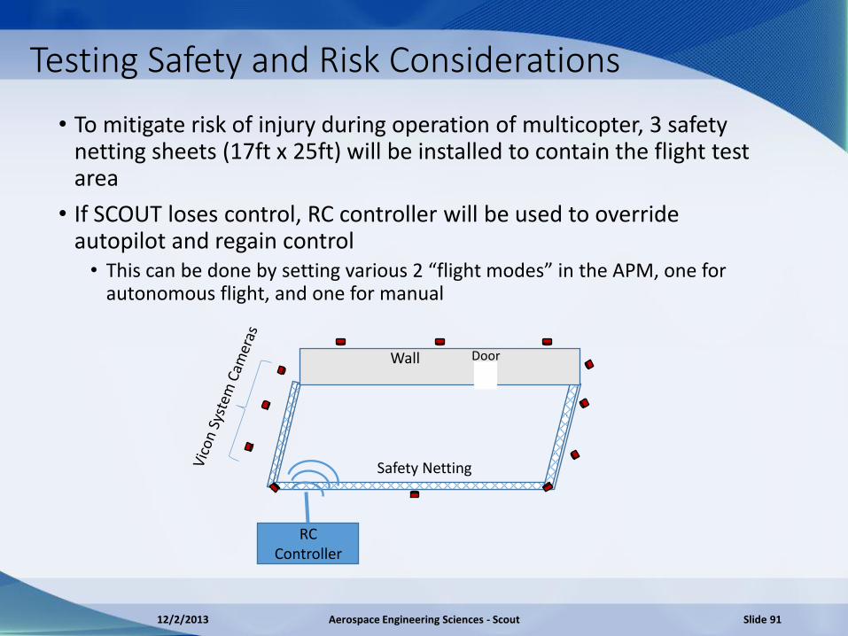
Testing Safety and Risk Considerations
• To mitigate risk of injury during operation of multicopter, 3 safety netting sheets (17ft x 25ft) will be installed to contain the flight test area
• If SCOUT loses control, RC controller will be used to override autopilot and regain control • This can be done by setting various 2 “flight modes” in the APM, one for
autonomous flight, and one for manual
RC Controller
Safety Netting
Wall Door
12/2/2013 Aerospace Engineering Sciences - Scout Slide 91