Embed Size (px)
Citation preview

*[email protected]; http://photonics.gsfc.nasa.gov
To be published in the proceedings for the SPIE Optical Engineering + Applications conference,
San Diego, California, August 28 to September 1, 2016. 1
Cryogenic fiber optic assemblies for spaceflight environments: design,
manufacturing, testing, and integration W. Joe Thomes*1, Melanie N. Ott1, Richard Chuska2, Robert Switzer2, Eleanya Onuma1, Diana
Blair2, Erich Frese2, Marc Matyseck2
1. NASA Goddard Space Flight Center, Greenbelt MD 20771
2. AS&D, Inc.
ABSTRACT
Fiber optic assemblies have been used on spaceflight missions for many years as an enabling technology for routing,
transmitting, and detecting optical signals. Due to the overwhelming success of NASA in implementing fiber optic
assemblies on spaceflight science-based instruments, system scientists increasingly request fibers that perform in extreme
environments while still maintaining very high optical transmission, stability, and reliability. Many new applications
require fiber optic assemblies that will operate down to cryogenic temperatures as low as 20 Kelvin. In order for the fiber
assemblies to operate with little loss in optical throughput at these extreme temperatures requires a system level approach
all the way from how the fiber assembly is manufactured to how it is held, routed, and integrated. The NASA Goddard
Code 562 Photonics Group has been designing, manufacturing, testing, and integrating fiber optics for spaceflight and
other high reliability applications for nearly 20 years. Design techniques and lessons learned over the years are consistently
applied to developing new fiber optic assemblies that meet these demanding environments. System level trades, fiber
assembly design methods, manufacturing, testing, and integration will be discussed. Specific recent examples of ground
support equipment for the James Webb Space Telescope (JWST); the Ice, Cloud and Land Elevation Satellite–2 (ICESat-
2); and others will be included.
Keywords: Spaceflight, Fiber Optic, Cryogenic, NASA, high reliability
1. INTRODUCTION
The NASA Goddard Space Flight Center (GSFC) Code 562 Photonics Group is world renowned for designing,
manufacturing, testing, and integrating custom high reliability fiber optic assemblies that operate in harsh environmental
conditions. For nearly 20 years the team has been developing innovative solutions for spaceflight and ground support
fiber assemblies to support NASA missions and external customers. In order to support the wide range of applications
being requested, custom components, processes, procedures, testing methods, and integration strategies have been
developed and are constantly being revised. Delivery of an optimal solution for a particular internal mission or external
customer needs to take into account all aspects of the intended implementation; including, but not limited to, optical
performance, environmental exposure, lifetime, integration, etc. Many of these aspects, with specific examples, will be
expanded upon in this paper.
Spaceflight and ground support systems are increasingly requiring components and subsystems that can operate and/or
survive at cryogenic temperatures. For the purposes of this paper, we will define cryogenic to be anything colder than
173K (-100°C). Typical refrigeration or liquid nitrogen cooled thermal ovens bottom out around -65°C. Applications for
cryogenic fiber optic assemblies range from fiber to send light to cryogenically cooled detectors to systems that are exposed
to deep space and shielded from the sun. Many papers have been published by our group and our colleagues regarding
recent examples of systems that utilized cryogenic fiber optic assemblies, but none of those papers has elaborated on the
design trades, specifics of final materials selections, testing, and integration that will be covered in this paper. A brief
overview of the missions that will be used as examples throughout the remainder of the paper will be provided. While
they do not cover all the cryogenic missions our group has been involved in over the past several years, each of these
missions was chosen because they offered unique requirements that drove their design selections. They also highlight the
system level trades needed to deliver the optimized solution for their particular needs and lessons learned on the necessity
to follow established implementation methods. The systems include: two testing systems for the James Webb Space
Telescope (JWST) (a) the Optical Telescope Element Simulator (OSIM) for testing the Integrated Science Instrument
Module (ISIM) and (b) the Aft Optical System (AOS) Source Plate Assembly (ASPA); the Ice, Cloud and Land Elevation
Satellite–2 (ICESat-2); and iLocater.
JWST is the successor to the Hubble Space Telescope. There have been a large number of papers published on JWST and
its various subsystems. The reader is referred to the NASA JWST website [1] as a starting point for detailed information.
https://ntrs.nasa.gov/search.jsp?R=20160010633 2018-07-07T03:50:53+00:00Z

To be published in the proceedings for the SPIE Optical Engineering + Applications conference,
San Diego, California, August 28 to September 1, 2016. 2
JWST is comprised of three main elements, the Integrated Science Instrument Module (ISIM), the Optical Telescope
Element (OTE), and the Spacecraft Element. The OTE comprises the mirrors, backplane, and supporting structure. The
Spacecraft Element comprises the spacecraft bus and sunshields. The ISIM houses the four main instruments on JWST:
Near Infrared Camera (NIRCam) operating at 0.6-5.0µm, Mid Infrared Camera (MIRI) operating at 5-28µm, Near Infrared
Spectrograph (NIRSpec) operating at 0.6-5.0µm, and Fine Guidance Sensor/Near Infrared Imager and Slitless
Spectrograph (FGS/NIRISS) operating at 0.8-4.8µm. These instruments were individually tested and delivered for
integration into the ISIM. Testing of the assembled ISIM with all science instruments installed, occurred in the GSFC
Space Environment Simulator (SES) Chamber. Optical stimulation of the ISIM detectors is provided by the OSIM. Figure
1 shows the environmental test setup in the SES chamber. Optical fibers route signals from outside the SES through fiber
vacuum feedthroughs over to the OSIM source plate. Detailed pictures of the fibers in the source plate can be found in
Figure 8.
Figure 1 JWST ISIM environmental test setup in the GSFC SES chamber. Shown is the OSIM used for optical stimulation of the four
science instruments housed on ISIM. Cryogenic fiber assemblies provide the optical signals to the OSIM source plate.
Upon completion of testing, ISIM will be integrated with OTE to form OTIS. This combined telescope and detector
system will undergo testing at Johnson Space Center (JSC) Chamber A. Optical stimulation will be provided by the ASPA,
which is a box that provides optical sources in precise locations located at the intermediate focal plane of the OTE. This
is the ideal location for providing optical test point sources. Optical signals will be sent from outside Chamber A through
fiber vacuum feedthroughs, over 50 meters of fiber to the ASPA. Fiber optic assemblies will pass through two shrouds,
across the thermal vacuum floor, through an interface plate, up a pole, across an arm (located above the primary mirrors)
and connect to the ASPA box. Figure 2 shows the configuration of the ASPA in relation to the OTIS on the left, and the
ASPA undergoing cryogenic testing in configuration of the right. The white cables going to ASPA are the cryogenic fiber
optics.
To be published in the proceedings for the SPIE Optical Engineering + Applications conference,
San Diego, California, August 28 to September 1, 2016. 3
Figure 2 JWST testing of the combined OTE and ISIM to form OTIS. Optical stimulation is provided by ASPA located at the
intermediate focal plane of the OTE. ASPA fiber optics was a collaboration of NASA GSFC and Ball Aerospace.
ICESat-2 is a follow-on mission to ICESat, which operated successfully from 2003-2009. The sole instrument on the
spacecraft is the Advanced Topographic Laser Altimeter System (ATLAS) instrument, which is a 532nm laser altimeter.
Fiber optics are used extensively to route optical signals between the many subsystems on the ATLAS instrument. The
reader is referred to the following references for more information: [2] [3] [4]. Ground support fiber optic cables route
optical signals to the ATLAS instrument during integration and environmental testing. These critical fiber optic assemblies
provide not only optical stimulus directly into key components on the spacecraft, but also connect the ground support
equipment (GSE) racks outside the environmental chambers to the various optical test systems located on or with the
spacecraft under test.
The iLocater is an ultra-precise planet-finding spectrometer that operates at infrared wavelengths. While still in the
development and demonstration phase, upon completion it aims to be the world's first diffraction-limited Doppler radial
velocity instrument. [5] Optical signals from the two telescopes of the Large Binocular Telescope Observatory (LBTO)
will be routed over a fiber optic assembly to the cryogenically cooled spectrometer. The iLocator is included as an example
of a system in development; a system that builds upon the cryogenic fiber optic assembly and array successful
implementations in a unique integration methodology.
2. DESIGN OF CRYOGENIC FIBER OPTIC ASSEMBLIES
Successful implementation and deployment of fiber optics in cryogenic environments involves an approach that addresses
all aspects of the fiber assemblies from initial materials selection, through manufacturing, and into integration. Mistakes,
oversights, or lack of discipline and experience in following the established methods during any one of these phases will
result in poor optical performance or failure (breakage) of the fiber. The design, testing, and integration methodologies
discussed in the following sections highlight the trades and some best practices for success, but all systems and
implementations are unique. This paper should serve as a starting point to guide the design trades, begin the planning and
implementation of testing regimes, and provide lessons learned for integration. All relevant system team representatives
(system, optical, thermal, mechanical, electrical engineers, ) should be involved throughout the various phases to alleviate
complications and compromises that could prevent successful deployment.
2.1 Requirements
One of the first steps in designing a fiber optic assembly or subsystem that must operate at very low temperatures is to
determine the driving requirements. Each mission or application will have a large number of requirements, such as
thermal, optical, mechanical, outgassing, and reliability/lifetime. While all of these are important, typically only a small
subset of them are absolutely vital to the packaging design. These few driving requirements will ultimately guide the
downselection of the design as the other requirements and preferences are negotiated to provide an optimal solution. Cost
and schedule are sometimes not included during technical trade discussions, but should never be ignored as they will also

To be published in the proceedings for the SPIE Optical Engineering + Applications conference,
San Diego, California, August 28 to September 1, 2016. 4
play a critical role in the downselection process at some point. Specific examples will be discussed on the downselection
process after a short description of primary requirement types and the issues regarding each. .
Thermal requirements
Thermal is obviously one of the key requirements for a cryogenic assembly. For most space missions, temperature ranges
are typically well defined and driven by the system or subsystems being connected together. Thermal requirements for a
spaceflight fiber assembly would include the operating range, survival range, qualification range, protoflight (if
applicable), and any other special thermal circumstances. Thermal requirements for ground support fiber assemblies
typically specify worst case thermal ranges that encompass all testing regimes for the linked systems in a space craft or
instrument. Ramp rates for each range should also be well defined, but can often times be negotiated if initially specified
as too aggressive. Further details will be discussed in the testing section of this paper, but for now it should be
acknowledged that different portions of the fiber optic cable will experience different temperatures during use and/or
testing. Minimizing the localized thermal gradients placed on the fiber assembly will improve optical performance and
reliability. Rapid thermal changes should be avoided or minimized to the extent possible. Thermal requirements like the
temperature ranges and ramp rates are the more obvious metrics, but several others need to be included in the initial design.
Decontamination bakeout temperatures will often dictate the upper temperature range of the assembly. But, designing a
cryogenic assembly to survive a hot bakeout will often times degrade its performance at cryogenic temperatures.
Decontamination, if required, can sometimes be performed at a lower temperature for longer duration. If decontamination
is conducted on a larger assembly that incorporates the fibers, then negotiation of the bakeout temperatures should be done
early in development to avoid damage to the fibers late in the lifecycle. If the system has shrouds to control the temperature
of the cryogenic portions of its contents, fiber pass-throughs are often employed. The large thermal gradient encountered
at the shroud interface needs to be considered with design options. Some final thermal considerations, often forgotten
during initial design, are related to thermal control. These include items like blanketing, heaters, sensors, etc. that can be
used to control thermal effects on portions of the fiber assembly, but can also impart mechanical stresses onto the assembly
once employed.
Optical requirements
Optical requirements include parameter such as; operating wavelength(s), fiber numerical aperture (NA), single-mode or
multi-mode fiber, and mode field diameter or fiber core size. These are typically dictated by the optical design of the
overall system. The optical throughput (percent transmission: %T) is usually as high as possible (sometimes represented
as a minimal insertion loss (IL)). However, the optical stability can sometimes be more important than the overall
transmission. Many systems utilize cryogenically cooled detectors to improve signal-to-noise (SNR) and reduce dark
current, and therefore stray light needs to be minimized.
Mechanical requirements
Mechanical requirements include: a) the physical properties of the fiber assembly such as; overall length, length tolerance,
cable diameter, fiber concentricity in the ferrule, etc.; b) environmental environments, such as shock, and vibration,; c)
handling constraints, such as cable ruggedness; and d) interfaces, such as vacuum feedthroughs, fiber connectors, and
adapter fixturing. Many of the mechanical requirements will be dictated by the system to which the fiber assembly
interfaces, but often the specifics about how the fiber interacts or its properties can be negotiated. For example, adding
enough length to provide a service loop into the cable to account for integration, routing changes, model imperfections or
how it is attached to the structure.
Vacuum requirements
Vacuum Outgassing requirements are sometimes dictated by the system.. For example, ground support fiber assemblies
for testing JWST had to have vacuum outgassing rates “in the noise” of expected outgassing from the JWST components
and subsystems. Basically they could not contribute any addition materials to the baseline outgassing rate from the
subsystems under test. Even when no outgassing requirement is specified for a particular system, outgassing always need
to be considered for cryogenic tests because anything coming off the fiber assembly in vacuum will preferentially redeposit
on the coldest items in the vacuum chamber. The interfacing system will often times have open optical elements or
detectors at cryogenic temperatures and therefore most depositing species will stick to those elements. A rule of thumb
when designing cryogenic fiber assemblies is to only use materials that pass ASTM E595 outgassing requirements. and
Even lower outgassing materials are needed in most cases where optics are used and in those cases, post manufacturing
bake outs are necessary. NASA maintains an outgassing database that can be consulted to look up previously tested

To be published in the proceedings for the SPIE Optical Engineering + Applications conference,
San Diego, California, August 28 to September 1, 2016. 5
materials [6]. Caution should be used when relying on the outgassing database as often times materials tested for
outgassing have been preconditioned or prepared in a specific manner. These conditions are captured in the database when
known, but are often excluded if performed prior to delivery to the GSFC Materials Branch for testing. Manufacturer lot-
to-lot variability will often dictate testing every new lot of materials to ensure no change has occurred from previous lots.
The GSFC Code 562 Photonics Group keeps extensive records and works closely with suppliers and manufacturers to
mitigate variability in products used for our internal manufacturing, but periodic checks are performed to ensure continual
required performance.
Lifetime and reliability
A requirement that is sometimes stated as a design goal, is the reliability or lifetime of the assembly. Spaceflight
application lifetimes of 5-10 years are typical, and up to 20-50 years depending on margin applied. For a ground support
cable, a lifetime of months to a year can often times be sufficient and fiber assemblies are sometimes swapped between
tests when they have been subjected to harsh environments. Often times for ground support cables it is more cost effective
to plan for replacement between tests than to implement the necessary fixturing, handling procedures, and keep-out zones
to ensure the continual reliability of the fibers. Once all the requirements have been identified and the primary driving
requirements determined, the design process involves identifying the fibers, connectors, jacketing, and how those materials
will be integrated into the system to meet those requirements. The GSFC Photonics Group team has been designing and
manufacturing high reliability fiber assemblies for harsh environments for nearly 20 years, so we have a large knowledge
base on what materials work together and how those combinations will perform over environments outside their typical
operating regime or beyond specification. Those years of lessons learned allow us to quickly select an optimized design
in spite of complex requirements. The basic principle is to minimize stresses and differential stresses applied to the fiber
during exposure to the environment, while still meeting the other driving requirements. Often times “you can’t have it
all”, so the design needs to address the driving requirements and then incorporate as much of the other requirements as
possible. Once the driving requirements are met, negotiations are conducted with the project or external customer to select
the best balance of the remaining desired metrics. It should be noted that the performance of some materials and fiber
optics at cryogenic temperatures can only be predicted through testing. An example of this with SM2000 fiber will be
given in the JWST ASPA design discussion.
2.2 Development of JWST OSIM Fiber Assemblies
Driving requirements for the JWST OSIM fiber assemblies were single mode operation at select wavelengths from 600nm
to over 2 µm. Fiber assemblies would be operating at 100K. While our team prefers to be involved in the design decisions
from the beginning, in this case optical fibers had already been selected by the optical team prior to our involvement. The
implementation consisted of four segments: 1) fibers from the source plate to an interface plate located on the OSIM
structure, 2) fibers from the interface plate to the vacuum chamber wall, 3) fiber vacuum feedthroughs, and 4) fibers from
the fiber vacuum feedthrough to the optical sources located outside the chamber. Testing of the ISIM instrument module
that OSIM was illuminating, occurred in the SES chamber at GSFC and therefore the routing of the fibers and their lengths
was dictated by the chamber layout. The fibers chosen were: Fibercore SM600, Fibercore SM980, Infrared Focal Systems
SG (ZBLAN), and CorActive IRT-SE-22-01. In addition, the project had our team investigate photonic crystal fibers:
NKT LMA-5 and Blaze Photonics ESM-12-01.
The fibers located in the OSIM source plate assembly needed to be located in close proximity to each other and in clusters
of four. To accommodate the close spacing, a custom ferrule holder was developed in collaboration with the OSIM
mechanical team. Custom Diamond AVIM ferrules were terminated without a connector body, held in place with springs,
and a custom “boot” that interfaced to a clamp on the ferrule holder were included in this adapter assembly. Figure 3
shows the fibers linking the source plate to the interface plate. To improve the optical performance of the fibers in this
region, no jacketing was used, and the fibers were supported by bars, with the entire area protected by an outer cover. This
assembly was not going to experience shock, vibration, or other sudden motions, so this implementation was acceptable
for this purpose. Diamond FC connectors were chosen for the interface plate connections. The FC connectors were used
with no secondary staking of the connector threads due to the absence of vibration loads. If the assembly was going to
experience vibration or other environments where the FC could come loose, a different connector would have been chosen
or secondary staking applied.

To be published in the proceedings for the SPIE Optical Engineering + Applications conference,
San Diego, California, August 28 to September 1, 2016. 6
Figure 3 Custom designed ferule holder on the OSIM source plate. Fiber assemblies linking the source plate to the interface plate.
Fibers going from the interface plate to the outside chamber wall needed additional protection, but were still protected in
dedicated routing trays along their entire length. For these segments, Diamond FC connectors were again chosen, along
with a custom manufactured ePTFE outer jacketing made by W.L. Gore to GSFC specifications. Figure 4 shows the fiber
assemblies and the custom fiber feedthroughs that interface with the SES chamber. The ePTFE custom jacketing was
chosen because it offers essentially no outgassing with proper preconditioning (testing to ASTM E-595 show TML of
0.01% and CVCM of 0.00%). The jacketing on these intermediate cables was crimped onto the fiber connector to improve
handling ruggedness due to routing concerns for integration.
Figure 4 Fiber assemblies from OSIM interface plate for linking to the vacuum fiber feedthroughs. Custom fiber vacuum
feedthroughs for interfacing to the SES chamber. All assemblies and feedthroughs manufactured by GSFC 562 Photonics Group.
Diamond FC connectors and AVIM ferrules were chosen for their high precision and ability to control the centering and
bond lines around the fiber endface. Our team has worked with Diamond for many years on custom solutions for
spaceflight and ground support cable components. Diamond was able to provide precisely toleranced ferrules in the
various sizes as they were specified, that we could then assemble onto the fibers during manufacturing.
In certain locations on the OSIM source plate, two separate fibers were required to deliver light for testing of the ISIM
instruments. To accommodate this requirement, a dual fiber ferrule was designed to allow placing two SM fibers into a
single ferrule. The fibers fanned out to individual connectors behind the ferrule and remained as separate fiber legs
throughout the remainder of the system. Due to the differential stress applied to the fiber in such a design, very tight

To be published in the proceedings for the SPIE Optical Engineering + Applications conference,
San Diego, California, August 28 to September 1, 2016. 7
control of tolerance and manufacturing processes is needed to produce an assembly that will survive at cryogenic
temperatures. While we had been designing and implementing fiber arrays for spaceflight for many years, this was the
first time the group had designed and implemented a fiber array for cryogenic temperatures.
Fibers designed for operation at infrared (IR) wavelengths tend to be more brittle than fused silica fibers due to their
constituent materials and dopants. The ZBLAN fibers specified by the OSIM team turned out to be excessively brittle.
Often times the fibers would break during unspooling or would crack just sitting on the bench with no external forces
applied. We worked with the manufacturer on several production lots to improve the mechanical strength of the fiber, but
ended up implementing a testing method to select portions of the fiber with enough strength to manufacture the required
cables. Alternative options for providing these wavelengths was also pursued. Arsenic selenide (AsSe) fibers had
strengths in between the fused silica fibers and the ZBLAN. They worked well at room temperatures, but were more brittle
at cryogenic temperatures. To minimize the stress on the fiber at cold temperatures, a lower cure temperature epoxy was
used, but that limited the ability to perform decontamination bake-outs at elevated temperatures.
2.3 Development of JWST ASPA Fiber Assemblies
The JWST ASPA assemblies had similar driving requirements to the OSIM assemblies, except the temperature of
operation was reduced to 30K with testing of the fiber assemblies to 20K. Ball Aerospace had ownership of the ASPA
and was the customer for these assemblies. Design and testing was a collaborative effort between our group and their
team. Based on lessons learned and recommendations from the OSIM system team, the following fibers were requested
for the ASPA design: Fibercore SM600, SM980, SM2000, and NKT LMA-10. The SM600, SM980, and SM2000 fibers
were to deliver the various test wavelengths from outside the vacuum chamber, through custom designed fiber vacuum
feedthroughs, to multiple segments of fiber inside the vacuum chamber. Photonics crystal fibers (LMA-10) were to be
used inside the ASPA to provide single mode outputs at all source locations. Initial testing revealed that the SM2000 fiber
did not continue guiding the IR light down to cryogenic temperatures. This was believed to be due to a change in the
materials refractive index with temperature that disrupted the confinement of the light in the fiber. [7] Based on our team’s
recommendation, the SM980 and SM2000 fibers were replaced by Corning ClearCurve Zero Bend Loss (ZBL) fiber (a
variation of SMF-28 and SMF-28e+), hereafter referred to as SMF28-ZBL. This fiber specifies operation from 1260nm
to 1800 nm, but has been found to operate further into the IR with careful handling. Further details will be provided in the
testing section of this paper. It should also be noted that although the LMA-10 fibers for inside the ASPA box were carried
in the design with full manufacturing processes developed and initial testing performed, it was discovered that the non-
circular nature of the output beam caused phase retrieval errors. So, the LMA-10 fibers were removed and replaced in the
design with SM600 and SMF-ZBL fibers inside the ASPA box all the way to the outputs. This is a good example of
various aspects of the team working together at an earlier phase to discover the possible problems with data reduction
(which typically happens toward the end of the program). By discovering this issue early, it could be corrected with little
to no impact to the cost or schedule of the program.
Given the close proximity of the fiber endfaces at the source output locations, a similar ferrule, spring, boot design was
used as on the OSIM design. However, in this case, protection of the fiber was needed inside the box because the entire
assembly would have to be rotated and moved, which required the fibers to be attached at several points inside the box.
To accommodate this requirement and still allow operation at temperatures down to 30K, a custom ePTFE jacket was
procured from W.L. Gore to GSFC (our) specification. This jacket was rigidly attached to the ferrule “boot” but allowed
to “float” at the Diamond AVIM interface of the ASPA box. The “floating” interface allowed the ePTFE jacketing to
contract at colder temperatures without stressing the fiber, but was designed to still constrain the jacketing so that it could
not pull out of the back of the connector. Outside of the ASPA box, two fiber segments were used to connect the optical
signals to the vacuum feedthroughs. The lengths of these fiber assemblies, operation at temperatures down to 30K, and
desire to have high and stable optical transmission drove the following development decisions. Diamond AVIM
connectors with custom ferrules were used at all interfaces. Fiber jacketing consisted of custom ePTFE jacketing with
“floating” interfaces of the jacketing to the connector to allow for thermal compensation. All fiber interfaces utilized
Diamond cleanable adapters. While this design allowed stable optical performance as will be shown in the testing section
of this paper, it also presented integration challenges as will be discussed in the integration section. However, this
combination was the optimal solution for this application.

To be published in the proceedings for the SPIE Optical Engineering + Applications conference,
San Diego, California, August 28 to September 1, 2016. 8
Figure 5 JWST ASPA cryogenic fiber assemblies and fiber vacuum feedthroughs designed and manufactured by GSFC Code 562
Photonics Group.
Optical signals were routed into the environmental test chambers at Ball Aerospace and later at the Johnson Space Center
Chamber A using custom designed fiber optic vacuum feedthroughs manufactured by our group. The feedthroughs
consisted of SM600 and SMF-ZBL fibers with Diamond AVIM connectors on both the inside and outside.
2.4 Development of ICESat-2 Fiber Assemblies
ICESat-2 and its instrument ATLAS required ground support fiber optic assemblies that could operate at -115°C. Fibers
were dictated by those already installed on the spacecraft and those needed for illumination of the various test equipment
installed inside the vacuum chamber. Fibers included: Nufern 460HP (SM fiber for 532nm), Fibercore SM630 (SM fiber
for 633nm), Polymicro Technologies FVA200220 and FVA400440. The cold temperatures are experienced at the shroud
inside the vacuum chamber all the way to the spacecraft. Due to handling, routing, and other activities being performed
inside the vacuum chamber after the fibers are installed, a more rugged jacketing was needed as compared to the JWST
cables discussed earlier. To accommodate the added protection, a CarlisleIT LITEflight® ND, NFO-HD, 3.8 mm outer
diameter jacketing was used with no pre-installed fibers. After proper preconditioning, the necessary fibers were installed
and terminated to Diamond AVIM connectors. Due to the added strength of the chosen Carlisle jacketing, the jacketing
is able to impose larger forces (stresses) on the connectors and fibers due to the CTE mismatch of the materials. To
improve the optical performance at cryogenic temperatures, a GSFC Code 562 Photonics Group custom designed
connector retainer was used to allow limited rotation and linear slip of the jacket with respect to the connector. But, unlike
the completely “floating” design of the JWST fiber assemblies, these assemblies had limited rotational ranges. The
integration complexities of these different designs will be discussed further in the integration section of this paper. For a

To be published in the proceedings for the SPIE Optical Engineering + Applications conference,
San Diego, California, August 28 to September 1, 2016. 9
further discussion of how the ATLAS ground support fiber assemblies integrated to the ATLAS instrument the reader is
referred to reference [3].
Figure 6 ATLAS ground support cryogenic fiber assemblies and feedthroughs for instrument thermal vacuum testing.
The custom connector retainer used on these cables has also been used on several other spaceflight and ground support
fiber assemblies. Even in more typical spacecraft thermal environments, controlling the thermally induced stresses on the
fiber assembly is essential to ensure high reliability and highest optical performance. Taking the fiber assembly to
temperatures outside the “normal” ranges, such as at cryogenic temperatures, makes this even more important.
2.5 Development of iLocater Fiber Assemblies
The iLocater project is still in the development and demonstration phase, but is included as an example of an application
that requires maximum optical transmission and fiber arrays at the cryogenically cooled spectrometer. To achieve the
absolute maximum optical throughput, continuous fibers are used all the way from the receiver telescopes to the cryogenic
spectrometer located inside a vacuum chamber. By removing all connectors in the fiber chain, optical losses are
minimized. Similar continuous fiber vacuum feedthroughs were designed and manufactured for ATLAS ground support
testing of the receiver telescope but are not discussed in this paper. While providing the highest optical performance, these
types of fiber assemblies are very difficult to integrate and offer a higher risk if damaged during integration and testing.
Removing and replacing a single cable, either ground support or flight, is complicated on a fully populated spacecraft.
However, removing and replacing a complete fiber harness, as these types of continuous fiber vacuum feedthroughs
typically incorporate many fibers that are routed to many different components, is very time consuming and introduces
risk to other installed hardware. Another feature of the iLocater fiber is the use of a multi-fiber bundle at the fiber output
into the cryogenic spectrometer. This will build on the success of the JWST, other cryogenic assembly development
efforts, and the successes of the flight array assemblies such as the ones designed for the ATLAS and the Lunar
Reconnaissance Orbiter. By controlling all aspects of the fiber(s), ferrule, epoxy, curing schedule, connector, and
termination; these types of multi-fiber arrays are now a low risk option for use in cryogenic or other demanding
applications.
3. MANUFACTURING OF CRYOGENIC FIBER OPTIC ASSEMBLIES
Designing the cryogenic fiber assemblies is a critical first step, but having a well-defined and controlled manufacturing
process is essential to ensure that design is implemented correctly. All of the criteria and processes used for manufacturing
high reliability spaceflight fiber assemblies apply when manufacturing fibers for use in other extreme environments. This
paper will not delve into the details of those processes, but the reader is referred to the large source of information available
on our website at [4]. A few highlights will be included to familiarize the reader with the rigor necessary to produce these
types of cables and how those methods differ from standard commercially available fiber assemblies.
All fibers, ferrules, connector components, jacketing/cabling materials, epoxies, etc. must go through an incoming and
receiving inspection to ensure they comply with necessary requirements. These requirements include not only the

To be published in the proceedings for the SPIE Optical Engineering + Applications conference,
San Diego, California, August 28 to September 1, 2016. 10
component manufacturer’s defined specifications, but also those requirements established by the entity performing the
manufacturing of the fiber assemblies or the end customer. For fiber assemblies manufactured by GSFC 562 Photonics
Group, we have worked with our suppliers for many years to define specifications for their supplies. Then all components
and/or lots are subjected to incoming and receiving inspections to ensure they perform as intended and compared to
previous orders. As an example, all fiber is procured unjacketed and subjected to a series of screening steps before
jacketing is applied. These steps include optical properties (IL, NA, etc.), physical properties (coating diameter, cladding
diameter, etc.), and strength (testing resulting in a Weibull statistical distribution to determine mechanical defect types).
For spaceflight use, other screening tests like radiation exposure are included. These screening tests are critical to avoiding
problems later during implementation of the fiber assemblies, but are often times skipped by outside vendors or
commercial entities as a cost and time savings. Many end users also don’t appreciate the criticality of these steps and
don’t want to pay for performing them. Unfortunately the ramifications of skipping these steps don’t show up until testing
in the integration and testing (I&T) phase of a program, where the cost to correct the problems are dramatically higher.
As a rather extreme example, the ZBLAN fiber used on the JWST OSIM cryogenic assemblies displayed a very large
distribution of defects and thus strengths within the fiber. Some spools of fiber would crack simply by unspooling the
fiber from its shipping spool. On other delivered spools, portions of the fiber would allow testing to typical tensile
strengths, while portion of the same spool would crack merely sitting on the bench. In the end, our group developed a
large tensile, pull testing station to screen long lengths of fiber. The fiber would be stressed and break (below the typical
breaking strength). The remaining section would be again stressed until it broke. This process would be repeated until a
section remained that possessed the strength necessary to manufacture a cryogenic assembly. Ultimately the variability in
strength was traced back to the manufacturing process used. This is a rather extreme example, but highlights the necessity
of the screening process. By working with well-established component manufacturers, the vast majority of materials pass
screening without incident, but variations in performance are discovered which can alter the subsequent processes before
and during manufacturing.
Another critical step in the early stages of manufacturing before fabrication of the cable assembly begins is
preconditioning. Many of the components that go into a fiber assembly have to be preconditioned to remove built-in
stresses and/or pass outgassing requirements. Our team has been brought in on many occasions to troubleshoot and
diagnose problems with commercially procured fiber assemblies that can be traced back to improper or incomplete
preconditioning. As a “best case” scenario, the fiber will only exhibit very large transcients in optical transmission if not
correctly preconditioned. Worst case, an incorrect preconditioning of the materials and components can result in
outgassing from the components contaminating everything inside the vacuum chamber and failure of the fiber assembly
in the form of extreme transmission degradation. Typically the bulk of outgassing happens primarily on the first couple
of thermal cycles under vacuum, whereas the fiber assembly will exhibit degrading optical performance with each
subsequent thermal cycle or over time if held at constant temperature. Therefore, it is essential that all materials and
components be properly preconditioned and verified before manufacturing begins.
The manufacturing of the fiber assemblies themselves needs to follow established processes and procedures similar to
other high reliability applications. Items like ensuring the epoxy is free of any bubbles during mixing, termination, and
curing are necessary to avoid non-uniform stresses on the fiber during exposure to cryogenic temperatures. The epoxy
used, its cure schedule, and other details all depend on the specific final use of the fiber assembly and are primarily
determined by experience and testing.
Also similar to spaceflight terminations and other high reliability applications, the inspection criteria for fiber endfaces
and their pass/fail specifications are more stringent than commercial standards. Minor defects in the fiber endface, when
subjected to high stresses imposed by the cold temperatures, can result in crack propagation into the fiber. Typical
inspection is performed at 400x magnification. No scratches, chips, divots, etc. are allowed on any portion of the fiber
endface or around its edges. Most commercial standards allow for minor defects in the fiber core and larger defects in the
cladding or edges. These defects act as nucleation sites for crack propagation and are therefore not allowed for cryogenic
assemblies. Non-uniform bond lines and/or large bond lines for adhesives are also not allowed.
Following manufacturing and inspection, workmanship testing is critical to screen the fibers for any manufacturing related
irregularities. It should be noted that workmanship testing is designed to screen for manufacturing anomalies and does
not take the place of qualification and prototype testing used to establish the specifics of the manufacturing process or
design for that application. Workmanship testing is designed as to not degrade the lifetime or reliability of the fiber
assemblies, whereas qualification testing intentionally stresses the fibers to levels beyond their intended use to ensure they
will reliably work throughout the mission.

To be published in the proceedings for the SPIE Optical Engineering + Applications conference,
San Diego, California, August 28 to September 1, 2016. 11
4. TESTING OF CRYOGENIC FIBER OPTIC ASSEMBLIES
Testing is performed at various stages throughout the development, manufacturing, and integration & test phases of a
project. In this section we will highlight some of the primary testing with examples from the representative projects being
discussed. Testing of the components and materials that go into a fiber assembly were covered in the manufacturing
section of this paper. One of the early tests conducted on cryogenic fiber assemblies during prototype development is
qualification. These tests are designed to subject representative fiber assemblies to conditions that meet and then exceed
the intended use conditions to determine performance of the fiber assembly and its reliability to perform in the actual use
condition. Qualification tests typically involve extended temperature ranges, additional cycles, and extended durations at
the temperature extremes. Figure 7 shows the in-situ testing setup for qualification testing of a representative 5.4 meter
SM600 cryogenic fiber assemblies for use on JWST ASPA. Since temperature use for ASPA is 30K, so qualification
testing was carried out to at least 20K (actual test temperature was 17K, the lower limit of the test chamber in this
configuration). Since the entire fiber would be exposed to cryogenic temperatures, the test consisted of an entire fiber
assembly located on the cryogenic cold plate inside the chamber. Lead-in and lead-out cables from the fiber vacuum
feedthrough, were routed to the cold plate with one loop located on the cold plate itself. Fiber connectors were also located
on the cold plate. By configuring the test in this manner, both connections and the entire cable were subjected to cryogenic
temperatures, similar to conditions experienced in actual use. Insertion loss changes of less than 0.2dB were observed,
with typical changes of around 0.1dB. No source monitoring was performed, so data has not been corrected for source
drift. For comparison, typical “good” SM fiber assemblies would be expected to swing by 0.8-1.0dB and commercial
assemblies would be expected to swing by 3dB or more (or fail completely).

To be published in the proceedings for the SPIE Optical Engineering + Applications conference,
San Diego, California, August 28 to September 1, 2016. 12
Figure 7 Qualification testing with in-situ monitoring of 5.4 meter SM600 fiber assemblies at 636nm for JWST ASPA. Cryogenic
cooler manually controlled, resulting in various durations at extremes. Insertion loss (IL) change of less than 0.2dB observed.
Based on these types of qualification tests, the fiber design and manufacturing processes are validated. Detailed procedures
are developed as part of the initial qualification test cable build and revised as necessary throughout qualification testing
if multiple iterations are needed. These procedures along with the other configuration management (CM) documentation
ensure subsequent cables are manufactured in a consistent manner.
Following manufacturing, workmanship testing is used to screen the fiber assemblies for abnormalities encountered during
the manufacturing process. Workmanship testing for spaceflight fiber assemblies typically involves thermal vacuum
testing at vacuum levels of 10-6 Torr and thermal ranges based on mission thermal ranges. [4] Similar processes are used
for cryogenic assemblies, where the cryogenic temperatures are chosen based on mission thermal ranges.
In certain circumstances, the fiber assemblies used for ground support may experience thermal ranges outside those of the
spacecraft itself. Such is the case with ICESat-2, in which the ground support fiber assemblies carrying optical signals to
the spacecraft under test, will be exposed to the cold shroud inside the vacuum chamber and between the shroud and optical
interface plate on the spacecraft. In this case, the connectors will be either close to room temperature at the fiber vacuum
feedthrough or controlled at the spacecraft interface, but long lengths of the fiber will be uncontrolled and allowed to reach
the shroud temperature. To test the optical performance of these fiber assemblies, tests were set up to either keep both
connectors at room temperature by connecting them to the fiber vacuum feedthrough or to keep one connector at an
intermediate temperature by attaching its fiber connector to the outer thermal shroud of the cryogenic chamber. Further
details of this test setup can be found in reference [3]. Due to the ruggedization of these cables with the stronger outer
jacket, their long lengths (50+ feet), and the expected thermal ranges; the cables had been designed to reduce stresses on
the fiber, but not eliminate it. Therefore, the optical throughput of these cables is expected to change during cryogenic
exposure. Single-mode fibers are less susceptible to stressing, except at the injection point, than larger core multimode
fibers. During testing is was observed that the single mode fibers for 532nm operation showed negligible changes in their
insertion loss (less than 0.1dB), while the 200 micron core fibers showed changes around 2.75dB and the 400 micron core
fibers showed losses in the 3.25dB to 3.5dB range. These optical transmission changes could be minimized with a redesign
of the fiber cable assembly, but represents the trades that are performed when selecting the best option for a particular
application. In this situation, the optical source ground support equipment has adjustability to compensate for the optical
transmission changes, so keeping the current configuration of a stiffer outer jacket was the preferred choice for handling
ease. It was also the case that under the circumstances the project decided that the existing assemblies could be used to
avoid additional costs since the -120°C requirement came after the assembly design was complete.
Testing fiber assemblies in their expected use configurations and attachment methods can expose “hidden” dangers that
can be avoided during integration and subsequent testing. A good example is the cryogenic fiber assemblies for JWST
ASPA. Extensive discussion and test results are given in [7], but summarized here. Early testing revealed the SM2000
fiber would not guide light at wavelengths beyond approximately 2µm at temperatures below 170K. Therefore, the fiber

To be published in the proceedings for the SPIE Optical Engineering + Applications conference,
San Diego, California, August 28 to September 1, 2016. 13
was replaced with Corning SMF-ZBL fiber during system development. In addition, it was discovered that taping the
fiber to the cold plate during testing resulted in high optical losses at cryogenic temperatures for IR wavelengths. These
types of tests drove the development of the integration strategy and fiber attachment methods, which will be discussed in
the next section.
This section has provided some highlights of various types of verification testing, but emphasis should be placed on the
fact that in-situ monitoring was used on the vast majority of these tests. Setting up in-situ monitoring is often times more
expensive and takes a little extra time. Although at times, avoiding in-situ monitoring may seem like an opportunity save
cost and schedule, it should not be avoided. The information gained from the fiber optic assembly’s performance at
temperature and the trend of that performance over thermal cycling is invaluable to determining its ultimate performance
in the intended application. Problems discovered and mitigated early on during fiber assembly level testing, will have
substantial cost and schedule savings by avoiding problems during integration and subsequent higher assembly level
testing, when the solution costs orders of magnitude more.
5. INTEGRATION OF CRYOGENIC FIBER OPTIC ASSEMBLIES
Once the fiber optic assemblies have been developed, manufactured, tested, and are ready for integration, any improper
installation, routing, or attachment can damage, destroy, or result in substandard optical performance. Exposing the fibers
to cryogenic temperatures exaggerates any integration problems by imposing unintended stresses on the fibers. Therefore
improper handling or routing can lead to degradation of the fiber link performance during the extreme thermal lower limit.
The following are guidelines to assist with developing a routing, integration, and attachment plan:
1. Hold the fibers gentle enough to allow slight slip in the clamps, but tight enough to prevent unwanted motion
over environments. Be careful of CTE difference changing the clamping force at cryogenic temperatures.
2. Keep bend radius as large as reasonably possible. Avoid sharp bends at all costs.
3. Avoid, where possible, routing other harnesses over or under the fibers. If unavoidable, provide fixturing to
prevent interference.
4. Use staff trained in handling high reliability fiber optics to integrate.
5. Use temporary fixturing where necessary to support fibers during integration.
6. Protect installed fibers during remainder of integration with temporary or permanent covers in critical areas.
7. Allow adequate time for integration. Don’t rush the installers. All fiber optic endfaces have to be inspected
and cleaned before attachment. Any contamination of the fiber endface will result in unstable optical
performance.
These general guidelines are a starting point. A detailed integration plan should be developed for more complex systems
and should include the use of highly trained installers for flight installations. The following are highlights of some of the
various methods used for attachment and integration on the example systems discussed in this paper.
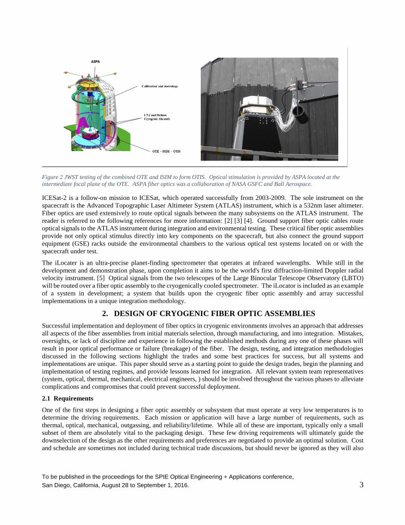
The JWST OSIM system used bare (coated but not jacketed) fibers in the source plate assembly, see Figure 8. Due to the
relatively fragile nature of these bare fibers, protective covers were used on all sides of this assembly. The assembled
system has successfully been used for testing the JWST ISIM at cryogenic temperatures. In this case, the lack of protective
jacketing on these fibers meant extra care in all aspects of manufacturing, testing, handling, packaging for delivery, and
integration.
To be published in the proceedings for the SPIE Optical Engineering + Applications conference,
San Diego, California, August 28 to September 1, 2016. 14
Figure 8 JWST OSIM cryogenic fiber assemblies integrated into the source plate (left) and installed on structure with covers (lower
portion of right picture).
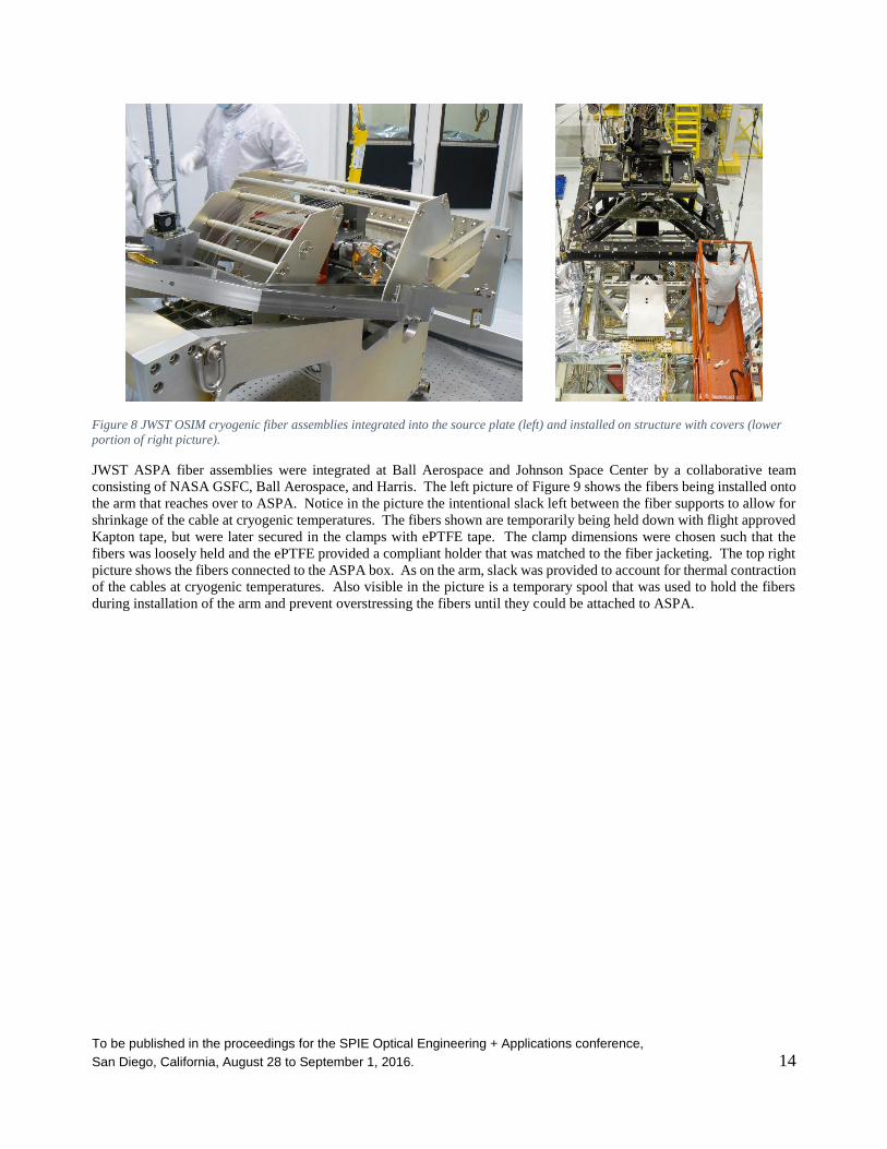
JWST ASPA fiber assemblies were integrated at Ball Aerospace and Johnson Space Center by a collaborative team
consisting of NASA GSFC, Ball Aerospace, and Harris. The left picture of Figure 9 shows the fibers being installed onto
the arm that reaches over to ASPA. Notice in the picture the intentional slack left between the fiber supports to allow for
shrinkage of the cable at cryogenic temperatures. The fibers shown are temporarily being held down with flight approved
Kapton tape, but were later secured in the clamps with ePTFE tape. The clamp dimensions were chosen such that the
fibers was loosely held and the ePTFE provided a compliant holder that was matched to the fiber jacketing. The top right
picture shows the fibers connected to the ASPA box. As on the arm, slack was provided to account for thermal contraction
of the cables at cryogenic temperatures. Also visible in the picture is a temporary spool that was used to hold the fibers
during installation of the arm and prevent overstressing the fibers until they could be attached to ASPA.

To be published in the proceedings for the SPIE Optical Engineering + Applications conference,
San Diego, California, August 28 to September 1, 2016. 15
Figure 9 JWST ASPA cryogenic fiber assemblies during integration. Left pictures shows the fibers installed on the arm leading over
to the ASPA box. Top right shows fibers connected to the ASPA (also shown is a temporary spool for holding the fibers during
integration. Bottom right shows part of the routing of the fibers between the thermal shroud and vacuum chamber wall.
The bottom right picture in Figure 9 shows a representative portion of the fiber routing between the ASPA and outside
vacuum wall. The fibers were supported in dedicated trays along the entire route. Portions inside the vacuum chamber
that had to be routed along the floor were encased in conduits to fully protect the fibers from inadvertent damage. The
picture shows the “take-up” region that allows for any additional length to be held without imparting stress onto the fiber.
This routing allowed the fibers to successfully transmit all test wavelengths from visible at 633nm to the IR at 2.1µm
without incident
The JWST OSIM and ASPA fiber assemblies were developed for optimal optical performance, and resulted in fiber
assemblies that took extra care and handling during integration. Since the connectors were only linearly constrained on
the fiber jacketing, no rotational limits were available. Thus, trained personnel had to install the fibers to avoid rotating
the AVIM connectors such that the fiber would be stressed and possibly break. Extra ground support fixtures had to be
utilized throughout integration. ATLAS, on the other hand, utilized fibers with a GSFC 562 Photonics Group designed
connector retainer that allowed controlled rotational motion while also providing linear slip for thermal compensation.
This allowed the fibers to be installed in several “blind mate” conditions where the fibers had to be inserted into their
adapters without being able to physically see the adapter during mating. The fiber assemblies also required fewer
protective conduits and were routed through passages with electrical cables. The added ruggedization came at a trade of
optimal optical performance at the lower temperatures.
Hopefully these examples have provided the reader with an appreciation of the complexities of fiber assembly integration
necessary to achieve optimal performance of the fiber assemblies in extreme conditions like cryogenic environments.
Integration methods and plans should be included as an ongoing part of the cryogenic fiber development process and plays
a key role in the initial development and testing phases, as well as the final installation.

To be published in the proceedings for the SPIE Optical Engineering + Applications conference,
San Diego, California, August 28 to September 1, 2016. 16
6. CONCLUSION
Cryogenic fiber optic assemblies are achievable with high reliability and optimal optical performance when a
comprehensive approach is taken that incorporates all aspects from development, manufacturing, testing, and integration.
REFERENCES
[1] "JWST," [Online]. Available: http://jwst.nasa.gov/.
[2] "ICESat-2," [Online]. Available: http://icesat.gsfc.nasa.gov/icesat2.
[3] Melanie N Ott, W. Joe Thomes, Eleanya Onuma, Robert Switzer, Richard Chuska, Diana Blair,
Erich Frese, Marc Matyseck, "The fiber optic system for the Advanced Topographic Laser
Altimeter System (ATLAS) instrument," SPIE Planetary Defense and Space Environmental
Applications Vol. 9981, August 2016.
[4] [Online]. Available: http://photonics.gsfc.nasa.gov.
[5] "iLocator," [Online]. Available: http://ilocater.nd.edu/.
[6] [Online]. Available: http://outgassing.nasa.gov.
[7] Ben Gallagher, Scott Knight, Allison Barto, W. Joe Thomes, Melanie Ott, "JWST ASPA fiber
optic development for testing at 2.12 um," SPIE Advances in Optical and Mechanical
Technologies for Telescopes and Instrumentation, Vol 9151, August 2014.