Embed Size (px)
Citation preview
CS1103
CS1104: Computer Organisation
http://www.comp.nus.edu.sg/~cs1104
Lecture 7: Combinational CircuitsMSI Components
CS1104-7 Lecture 7: Combinational Circuits: MSI Components
2
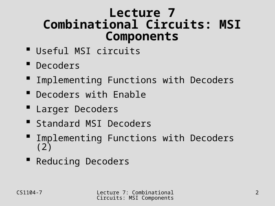
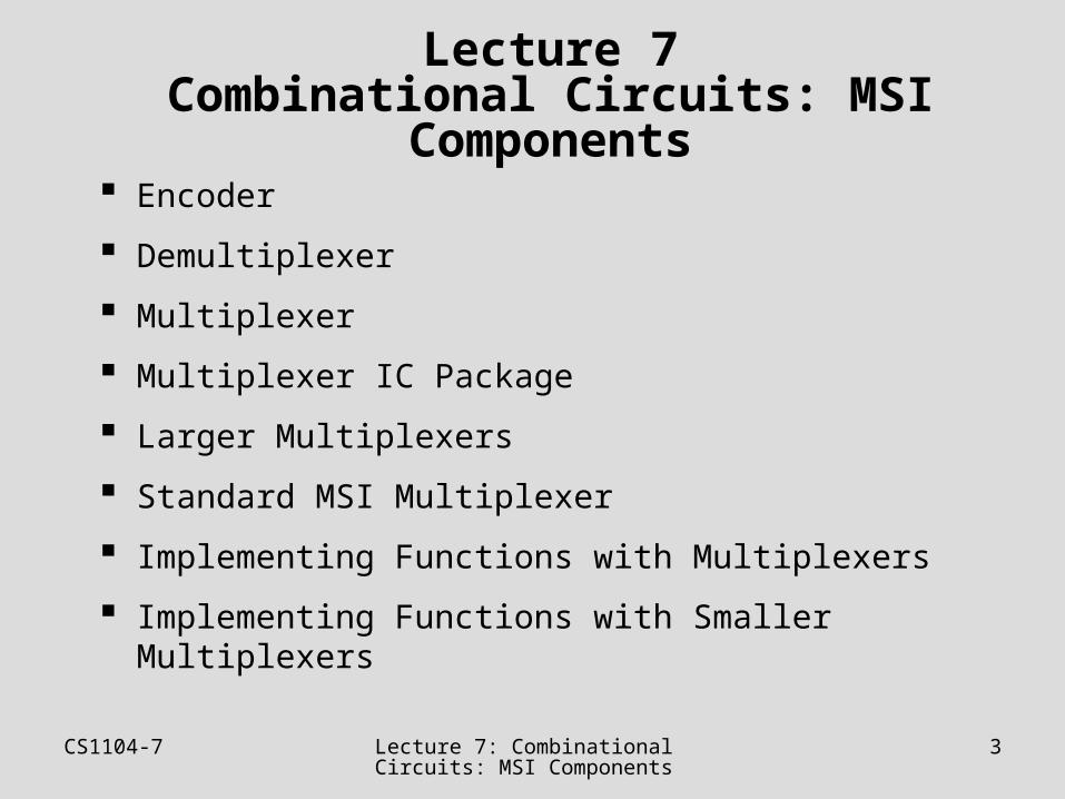
Lecture 7Combinational Circuits: MSI Components
Useful MSI circuits
Decoders
Implementing Functions with Decoders
Decoders with Enable
Larger Decoders
Standard MSI Decoders
Implementing Functions with Decoders (2)
Reducing Decoders
CS1104-7 Lecture 7: Combinational Circuits: MSI Components
3
Lecture 7Combinational Circuits: MSI Components
Encoder
Demultiplexer
Multiplexer
Multiplexer IC Package
Larger Multiplexers
Standard MSI Multiplexer
Implementing Functions with Multiplexers
Implementing Functions with Smaller Multiplexers
CS1104-7 Useful MSI circuits 4
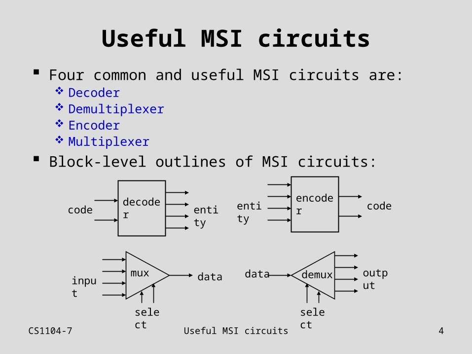
Useful MSI circuits Four common and useful MSI circuits are:
Decoder Demultiplexer Encoder Multiplexer
Block-level outlines of MSI circuits:
decodercode entity
encodercodeentity
mux datainput
select
demuxdata output
select
CS1104-7 Decoders 5
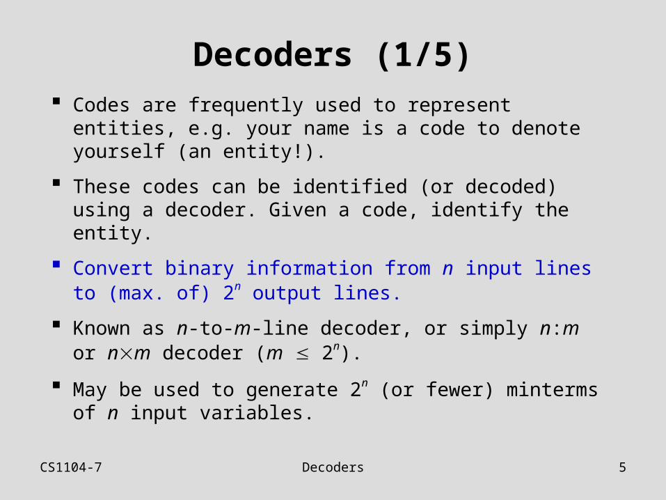
Decoders (1/5) Codes are frequently used to represent entities, e.g.
your name is a code to denote yourself (an entity!).
These codes can be identified (or decoded) using a decoder. Given a code, identify the entity.
Convert binary information from n input lines to (max. of) 2n output lines.
Known as n-to-m-line decoder, or simply n:m or nm decoder (m 2n).
May be used to generate 2n (or fewer) minterms of n input variables.
CS1104-7 Decoders 6
Decoders (2/5)
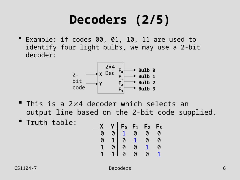
Example: if codes 00, 01, 10, 11 are used to identify four light bulbs, we may use a 2-bit decoder:
2x4Dec2-bit
codeX
Y
F0
F1
F2
F3
Bulb 0Bulb 1Bulb 2Bulb 3
This is a 24 decoder which selects an output line based on the 2-bit code supplied.
Truth table: X Y F0 F1 F2 F3
0 0 1 0 0 00 1 0 1 0 01 0 0 0 1 01 1 0 0 0 1
CS1104-7 Decoders 7
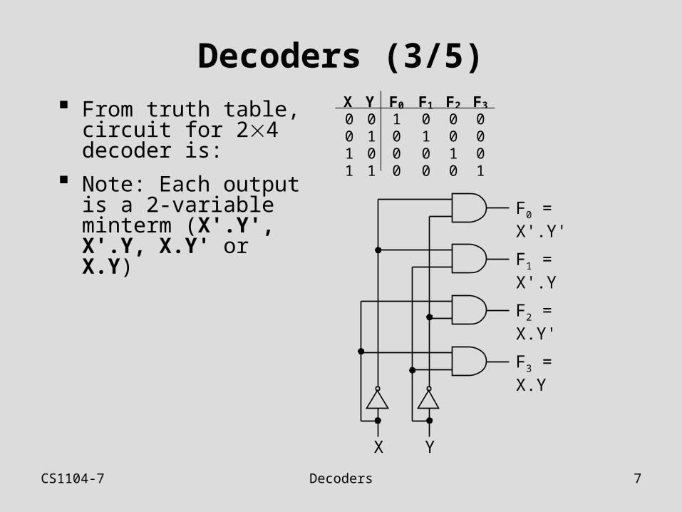
Decoders (3/5) From truth table,
circuit for 24 decoder is:
Note: Each output is a 2-variable minterm (X'.Y', X'.Y, X.Y' or X.Y)
X Y F0 F1 F2 F3
0 0 1 0 0 00 1 0 1 0 01 0 0 0 1 01 1 0 0 0 1
F0 = X'.Y'
F1 = X'.Y
F2 = X.Y'
F3 = X.Y
X Y
CS1104-7 Decoders 8
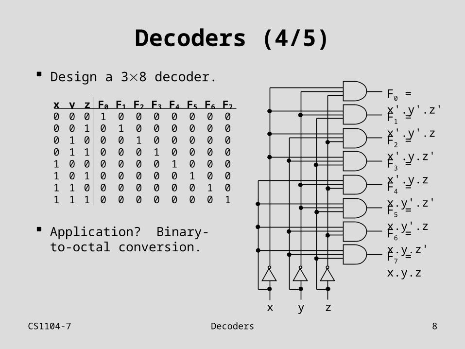
Decoders (4/5)
Design a 38 decoder.
x y z F0 F1 F2 F3 F4 F5 F6 F7
0 0 0 1 0 0 0 0 0 0 00 0 1 0 1 0 0 0 0 0 00 1 0 0 0 1 0 0 0 0 00 1 1 0 0 0 1 0 0 0 01 0 0 0 0 0 0 1 0 0 01 0 1 0 0 0 0 0 1 0 01 1 0 0 0 0 0 0 0 1 01 1 1 0 0 0 0 0 0 0 1
F1 = x'.y'.z
x zy
F0 = x'.y'.z'
F2 = x'.y.z'
F3 = x'.y.z
F5 = x.y'.z
F4 = x.y'.z'
F6 = x.y.z'
F7 = x.y.z
Application? Binary-to-octal conversion.
CS1104-7 Decoders 9
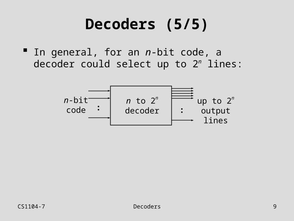
Decoders (5/5)
In general, for an n-bit code, a decoder could select up to 2n lines:
: :n-bitcode
n to 2n
decoderup to 2n
output lines
CS1104-7 Decoders: Implementing Functions
10
Decoders: Implementing Functions (1/5)
A Boolean function, in sum-of-minterms form decoder to generate the minterms, and an OR gate to form the sum.
Any combinational circuit with n inputs and m outputs can be implemented with an n:2n decoder with m OR gates.
Good when circuit has many outputs, and each function is expressed with few minterms.
CS1104-7 Decoders: Implementing Functions
11
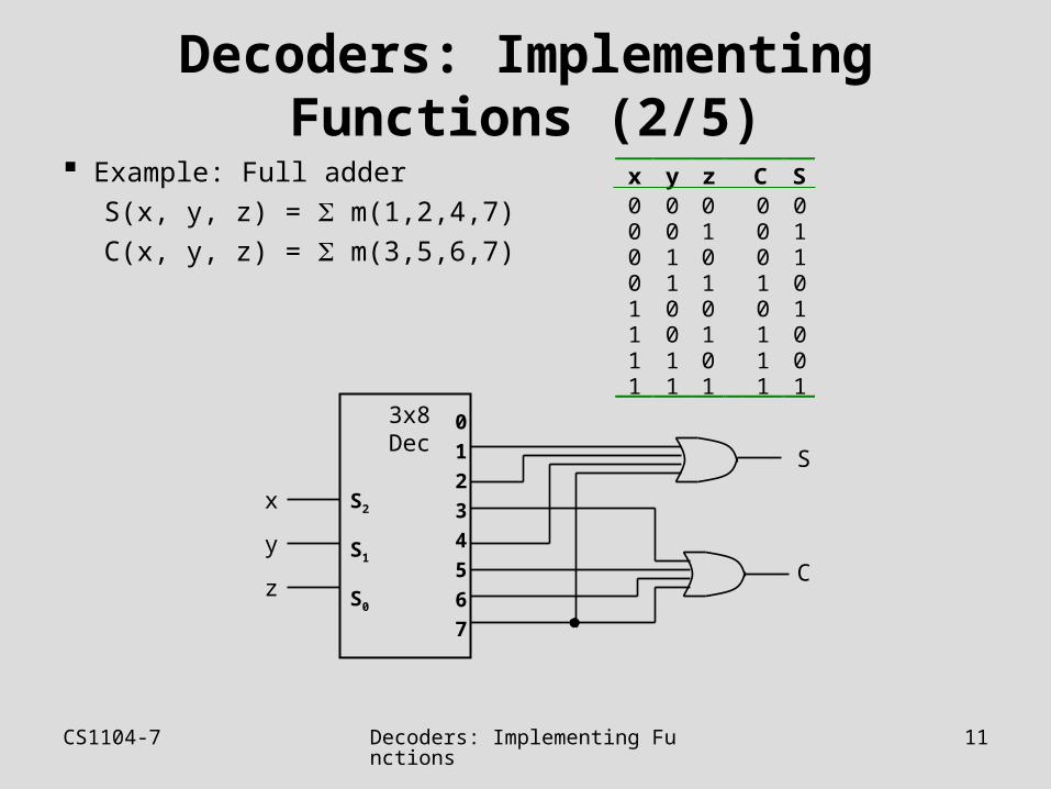
Decoders: Implementing Functions (2/5)
Example: Full adder
S(x, y, z) = m(1,2,4,7)
C(x, y, z) = m(3,5,6,7)
3x8Dec
S2
S1
S0
x
y
z
0
1
2
3
4
5
6
7
S
C
x y z C S0 0 0 0 00 0 1 0 10 1 0 0 10 1 1 1 01 0 0 0 11 0 1 1 01 1 0 1 01 1 1 1 1
CS1104-7 Decoders: Implementing Functions
12
Decoders: Implementing Functions (3/5)
3x8Dec
S2
S1
S0
x
y
z
0
1
2
3
4
5
6
7
S
C
x y z C S0 0 0 0 00 0 1 0 10 1 0 0 10 1 1 1 01 0 0 0 11 0 1 1 01 1 0 1 01 1 1 1 1
10000000
0
0
0
0
0
CS1104-7 Decoders: Implementing Functions
13
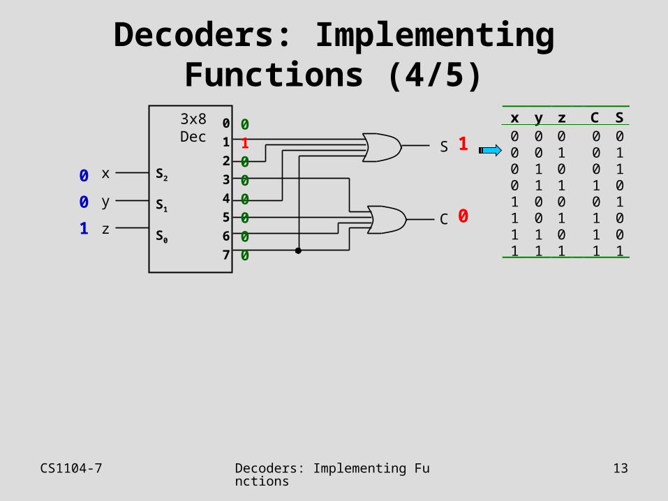
Decoders: Implementing Functions (4/5)
3x8Dec
S2
S1
S0
x
y
z
0
1
2
3
4
5
6
7
S
C
x y z C S0 0 0 0 00 0 1 0 10 1 0 0 10 1 1 1 01 0 0 0 11 0 1 1 01 1 0 1 01 1 1 1 1
01000000
1
0
0
0
1
CS1104-7 Decoders: Implementing Functions
14
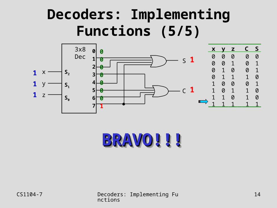
Decoders: Implementing Functions (5/5)
3x8Dec
S2
S1
S0
x
y
z
0
1
2
3
4
5
6
7
S
C
x y z C S0 0 0 0 00 0 1 0 10 1 0 0 10 1 1 1 01 0 0 0 11 0 1 1 01 1 0 1 01 1 1 1 1
00000001
1
1
BRAVO!!!BRAVO!!!BRAVO!!!BRAVO!!!
1
1
1
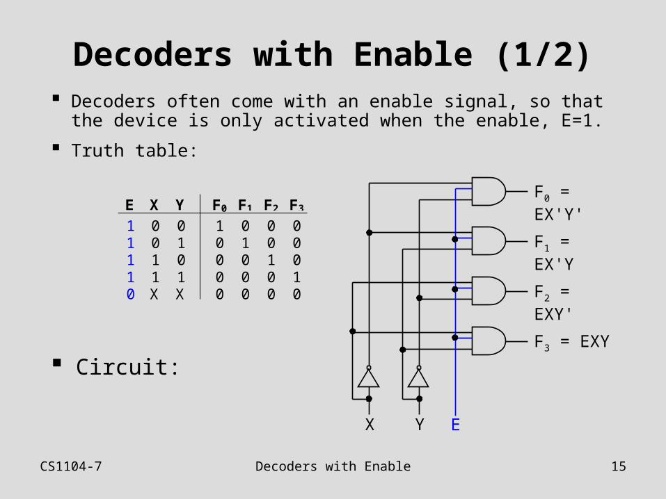
CS1104-7 Decoders with Enable 15
Decoders with Enable (1/2) Decoders often come with an enable signal, so that
the device is only activated when the enable, E=1.
Truth table:
E X Y F0 F1 F2 F3
1 0 0 1 0 0 01 0 1 0 1 0 01 1 0 0 0 1 01 1 1 0 0 0 10 X X 0 0 0 0
F0 = EX'Y'
F1 = EX'Y
F2 = EXY'
F3 = EXY
X Y E
Circuit:
CS1104-7 Decoders with Enable 16
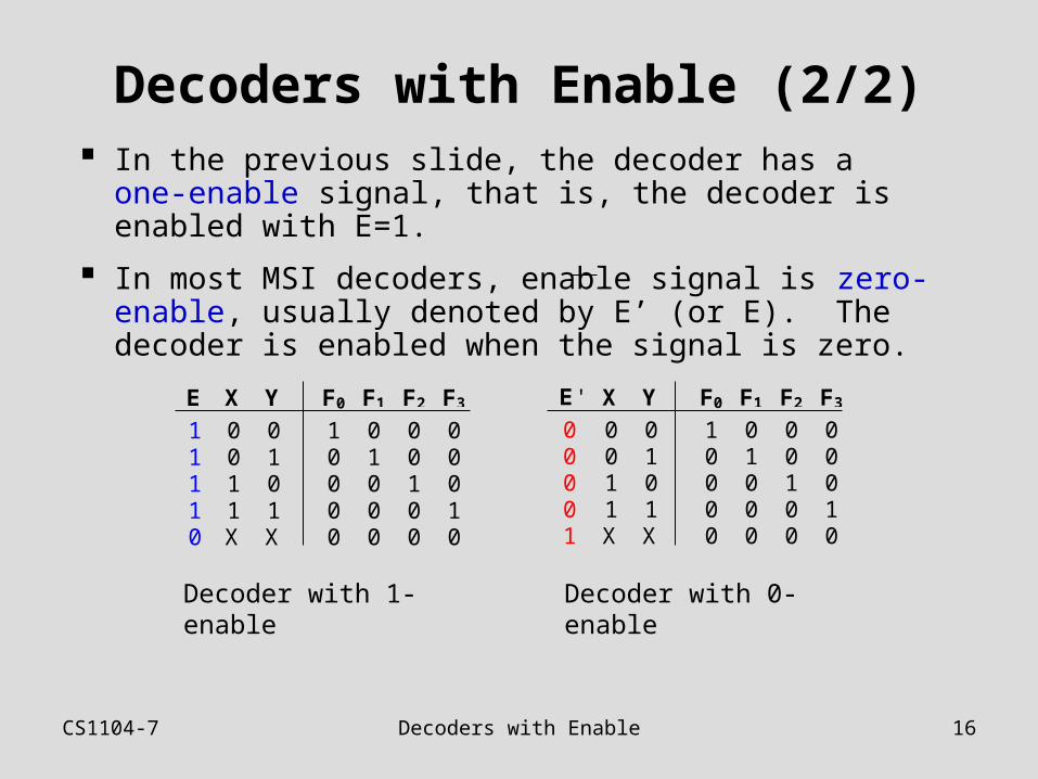
Decoders with Enable (2/2) In the previous slide, the decoder has a one-enable
signal, that is, the decoder is enabled with E=1.
In most MSI decoders, enable signal is zero-enable, usually denoted by E’ (or E). The decoder is enabled when the signal is zero.
E X Y F0 F1 F2 F3
1 0 0 1 0 0 01 0 1 0 1 0 01 1 0 0 0 1 01 1 1 0 0 0 10 X X 0 0 0 0
E' X Y F0 F1 F2 F3
0 0 0 1 0 0 00 0 1 0 1 0 00 1 0 0 0 1 00 1 1 0 0 0 11 X X 0 0 0 0
Decoder with 1-enable Decoder with 0-enable
CS1104-7 Larger Decoders 17
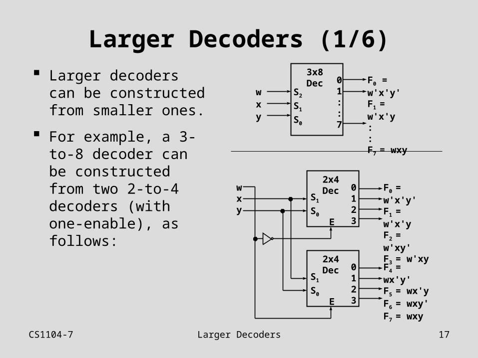
Larger Decoders (1/6) Larger decoders can
be constructed from smaller ones.
For example, a 3-to-8 decoder can be constructed from two 2-to-4 decoders (with one-enable), as follows:
3x8Dec
S2
S1
S0
wxy
01::7
F0 = w'x'y'F1 = w'x'y::F7 = wxy
2x4Dec
S1
S0
0123
F0 = w'x'y'F1 = w'x'yF2 = w'xy'F3 = w'xyE
2x4Dec
S1
S0
0123
F4 = wx'y'F5 = wx'yF6 = wxy'F7 = wxyE
wxy

CS1104-7 Larger Decoders 18
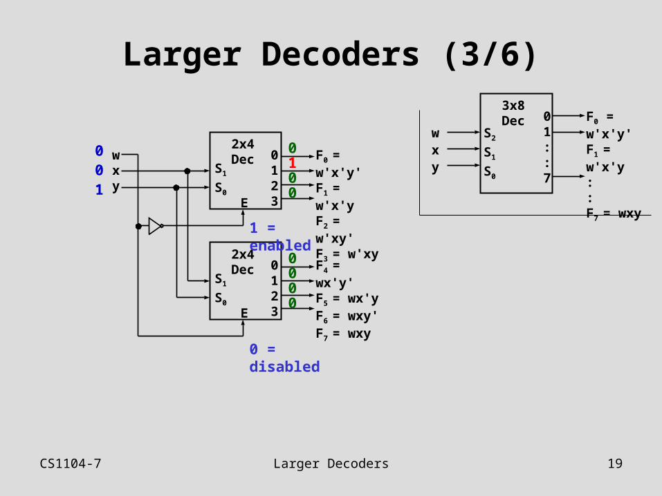
Larger Decoders (2/6)3x8Dec
S2
S1
S0
wxy
01::7
F0 = w'x'y'F1 = w'x'y::F7 = wxy
2x4Dec
S1
S0
0123
F0 = w'x'y'F1 = w'x'yF2 = w'xy'F3 = w'xyE
2x4Dec
S1
S0
0123
F4 = wx'y'F5 = wx'yF6 = wxy'F7 = wxyE
wxy
000
0000
1000
0 = disabled
1 = enabled
CS1104-7 Larger Decoders 19
Larger Decoders (3/6)3x8Dec
S2
S1
S0
wxy
01::7
F0 = w'x'y'F1 = w'x'y::F7 = wxy
2x4Dec
S1
S0
0123
F0 = w'x'y'F1 = w'x'yF2 = w'xy'F3 = w'xyE
2x4Dec
S1
S0
0123
F4 = wx'y'F5 = wx'yF6 = wxy'F7 = wxyE
wxy
001
0000
0100
0 = disabled
1 = enabled
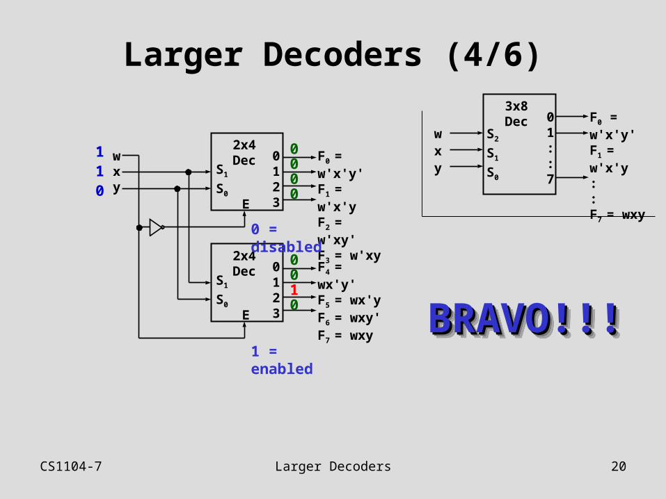
CS1104-7 Larger Decoders 20
Larger Decoders (4/6)3x8Dec
S2
S1
S0
wxy
01::7
F0 = w'x'y'F1 = w'x'y::F7 = wxy
2x4Dec
S1
S0
0123
F0 = w'x'y'F1 = w'x'yF2 = w'xy'F3 = w'xyE
2x4Dec
S1
S0
0123
F4 = wx'y'F5 = wx'yF6 = wxy'F7 = wxyE
wxy
110
0010
0000
1 = enabled
0 = disabled
BRAVO!!!BRAVO!!!BRAVO!!!BRAVO!!!
CS1104-7 Larger Decoders 21
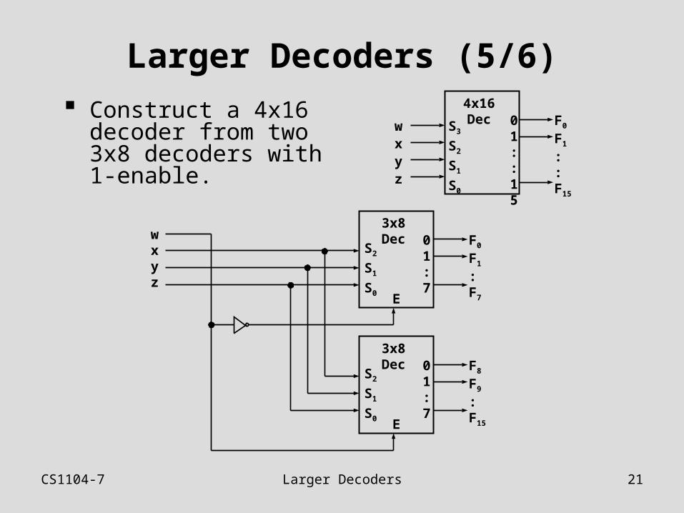
Larger Decoders (5/6) Construct a 4x16
decoder from two 3x8 decoders with 1-enable.
4x16DecS3
S2
S1
S0
wxyz
01::
15
F0
F1
::F15
3x8Dec
S2
S1
S0
01:7
F0
F1
:F7E
3x8Dec
S2
S1
S0
01:7
F8
F9
:F15E
wxyz
CS1104-7 Larger Decoders 22
Larger Decoders (6/6)
Note: The input, w and its complement, w', is used to select either one of the two smaller decoders.
Decoders may also have zero-enable and/or negated outputs. (Normal outputs = active high; negated outputs = active low.)
Exercise: What modifications must be made to provide an ENABLE input for the 3x8 decoder (2 slides ago) and the 4x16 decoder (previous slide) created?
Exercise: How to construct a 4x16 decoder using five 2x4 decoders with enable?
CS1104-7 Standard MSI Decoders 23
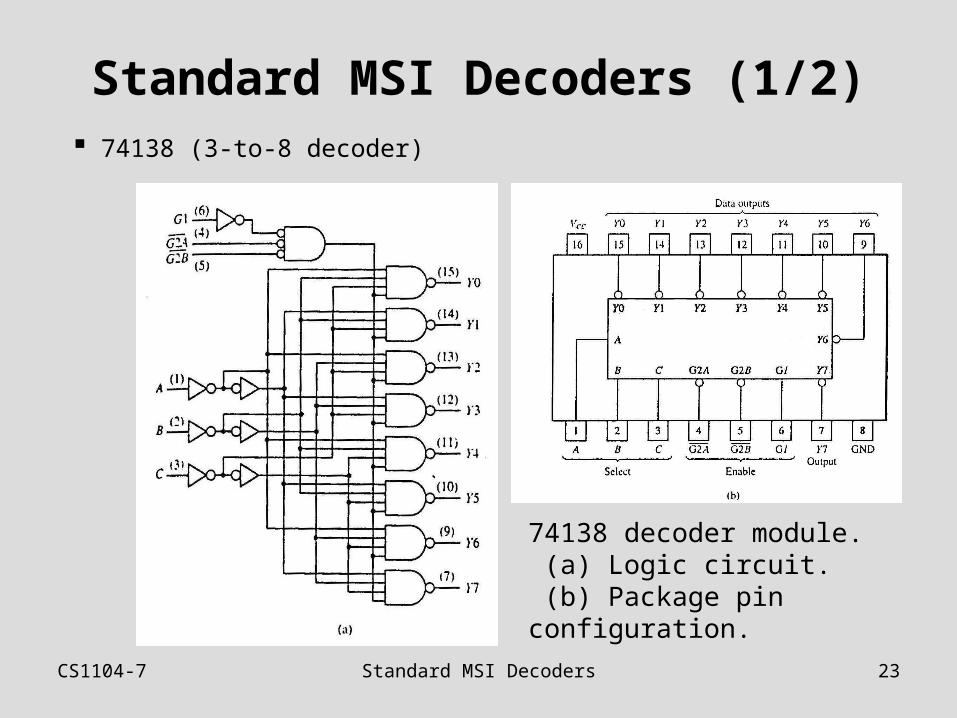
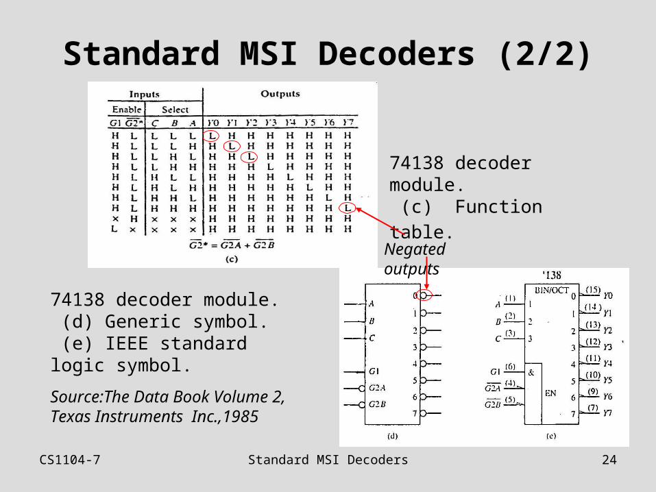
Standard MSI Decoders (1/2) 74138 (3-to-8 decoder)
74138 decoder module. (a) Logic circuit. (b) Package pin configuration.
CS1104-7 Standard MSI Decoders 24
Standard MSI Decoders (2/2)
74138 decoder module.
(c) Function table.
74138 decoder module. (d) Generic symbol. (e) IEEE standard logic symbol.
Source:The Data Book Volume 2, Texas Instruments Inc.,1985
Negated outputs
CS1104-7 Decoders: Implementing Functions (2)
25
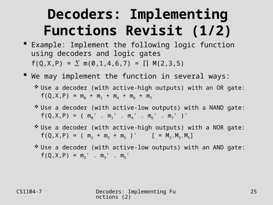
Decoders: Implementing Functions Revisit (1/2)
Example: Implement the following logic function using decoders and logic gates
f(Q,X,P) = m(0,1,4,6,7) = M(2,3,5)
We may implement the function in several ways:
Use a decoder (with active-high outputs) with an OR gate:f(Q,X,P) = m0 + m1 + m4 + m6 + m7
Use a decoder (with active-low outputs) with a NAND gate:f(Q,X,P) = ( m0' . m1' . m4' . m6' . m7' )'
Use a decoder (with active-high outputs) with a NOR gate:f(Q,X,P) = ( m2 + m3 + m5 )' [ = M2.M3.M5]
Use a decoder (with active-low outputs) with an AND gate:f(Q,X,P) = m2' . m3' . m5'
CS1104-7 Decoders: Implementing Functions (2)
26
Decoders: Implementing Functions Revisit (2/2)
3x8Dec
A
B
C
Q
X
P
01234567
f(Q,X,P) f(Q,X,P)
3x8Dec
A
B
C
Q
X
P
01234567
3x8Dec
A
B
C
Q
X
P
01234567
f(Q,X,P) f(Q,X,P)
3x8Dec
A
B
C
Q
X
P
01234567
(a) Active-high decoder with OR gate. (b) Active-low decoder with NAND gate.
(c) Active-high decoder with NOR gate. (d) Active-low decoder with AND gate.
f(Q,X,P) = m(0,1,4,6,7)
CS1104-7 Reducing Decoders 27
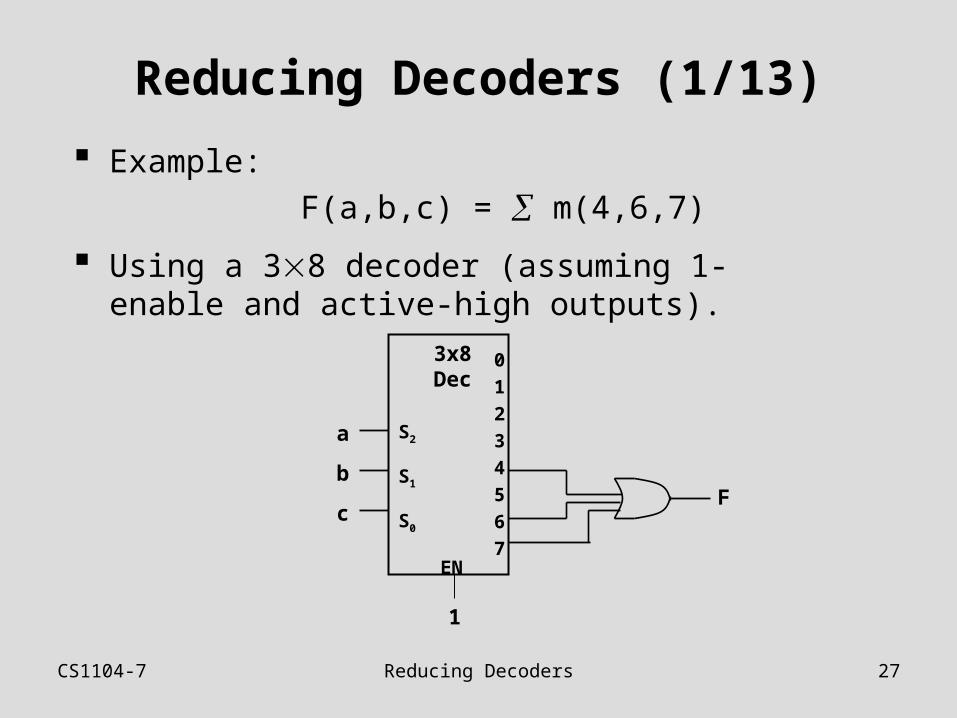
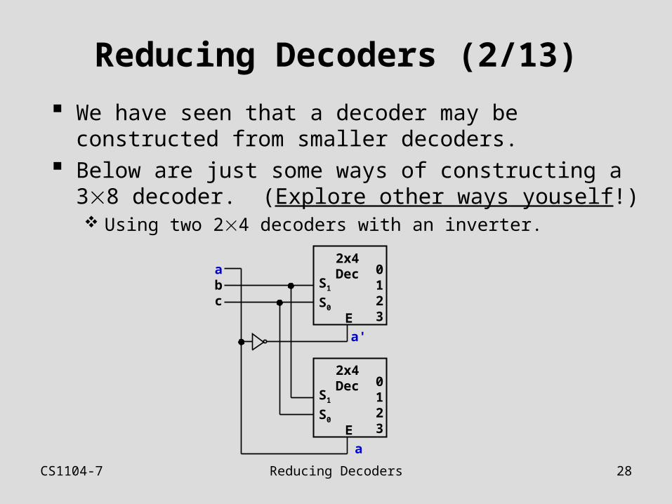
Reducing Decoders (1/13)
Example:
F(a,b,c) = m(4,6,7)
Using a 38 decoder (assuming 1-enable and active-high outputs).
3x8Dec
S2
S1
S0
a
b
c
0
1
2
3
4
5
6
7
F
EN
1
CS1104-7 Reducing Decoders 28
Reducing Decoders (2/13)
We have seen that a decoder may be constructed from smaller decoders.
Below are just some ways of constructing a 38 decoder. (Explore other ways youself!) Using two 24 decoders with an inverter.
2x4Dec
S1
S0
0123E
2x4Dec
S1
S0
0123E
abc
a'
a
CS1104-7 Reducing Decoders 29
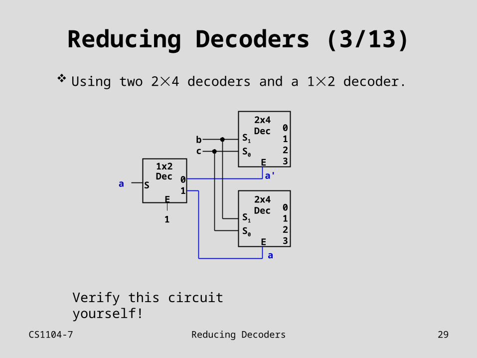
Reducing Decoders (3/13)
Using two 24 decoders and a 12 decoder.
2x4Dec
S1
S0
0123E
2x4Dec
S1
S0
0123E
bc
a'
a
1x2Dec
S01
E
a
1
Verify this circuit yourself!
CS1104-7 Reducing Decoders 30
Reducing Decoders (4/13)
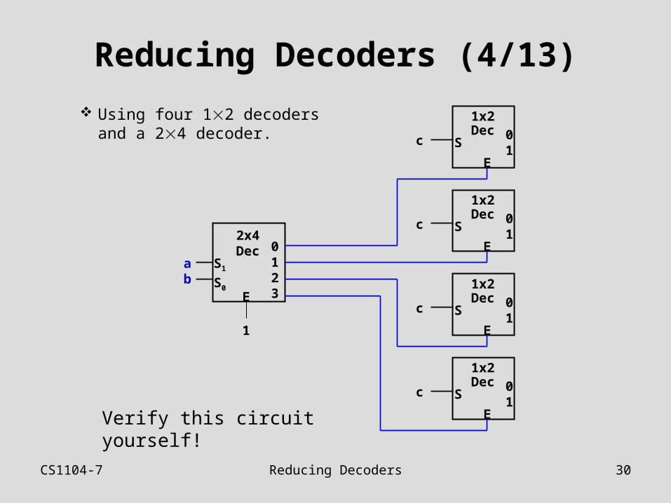
Using four 12 decoders and a 24 decoder.
Verify this circuit yourself!
2x4Dec
S1
S0
0123E
1x2Dec
S01
E
ab
1
1x2Dec
S01
E
1x2Dec
S01
E
1x2Dec
S01
E
c
c
c
c
CS1104-7 Reducing Decoders 31
Reducing Decoders (5/13)
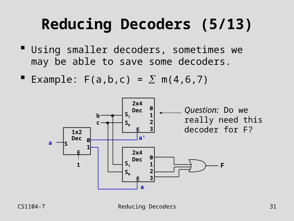
Using smaller decoders, sometimes we may be able to save some decoders.
Example: F(a,b,c) = m(4,6,7)
F
2x4Dec
S1
S0
0123E
2x4Dec
S1
S0
0123E
bc
a'
a
1x2Dec
S01
E
a
1
Question: Do we really need this decoder for F?
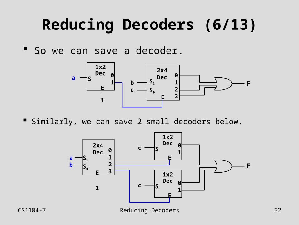
CS1104-7 Reducing Decoders 32
Reducing Decoders (6/13)
So we can save a decoder.
F
2x4Dec
S1
S0
0123E
bc
1x2Dec
S01
E
a
1
Similarly, we can save 2 small decoders below.
2x4Dec
S1
S0
0123E
ab
1
1x2Dec
S01
E
1x2Dec
S01
E
c
c
F
CS1104-7 Reducing Decoders 33
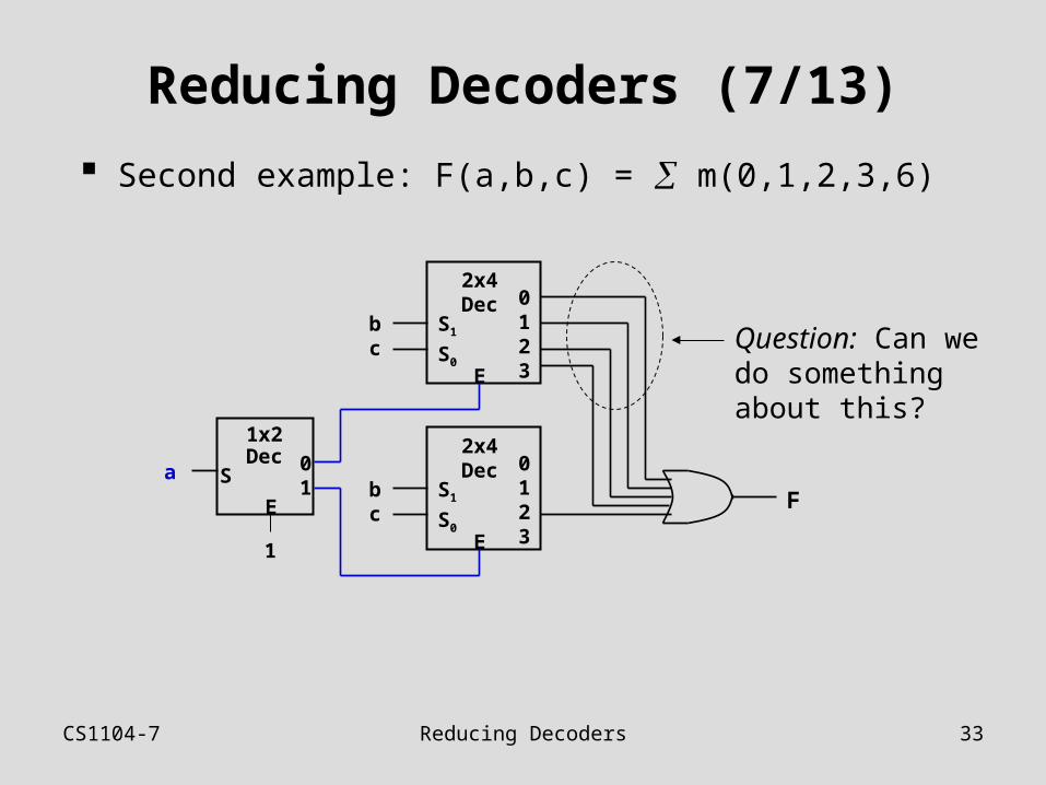
Reducing Decoders (7/13)
Second example: F(a,b,c) = m(0,1,2,3,6)
F
2x4Dec
S1
S0
0123E
bc
1x2Dec
S01
E
a
1
2x4Dec
S1
S0
0123E
bc Question: Can we
do something about this?
CS1104-7 Reducing Decoders 34
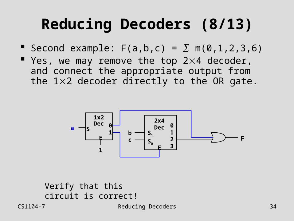
Reducing Decoders (8/13)
Second example: F(a,b,c) = m(0,1,2,3,6) Yes, we may remove the top 24 decoder, and
connect the appropriate output from the 12 decoder directly to the OR gate.
F
2x4Dec
S1
S0
0123E
bc
1x2Dec
S01
E
a
1
Verify that this circuit is correct!
CS1104-7 Reducing Decoders 35
Reducing Decoders (9/13)
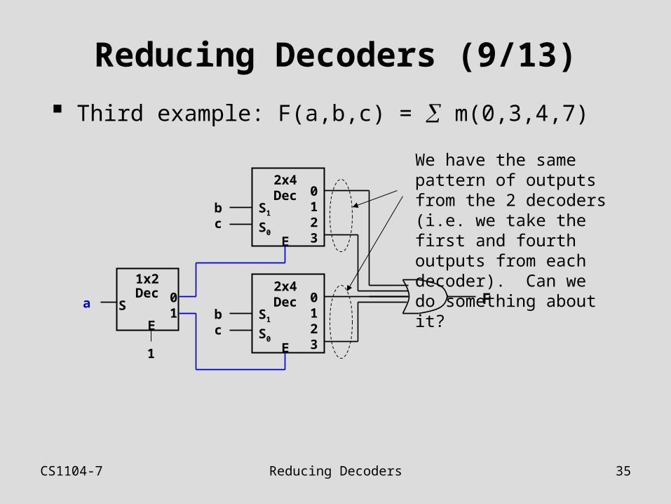
Third example: F(a,b,c) = m(0,3,4,7)
F2x4Dec
S1
S0
0123E
bc
1x2Dec
S01
E
a
1
2x4Dec
S1
S0
0123E
bc
We have the same pattern of outputs from the 2 decoders (i.e. we take the first and fourth outputs from each decoder). Can we do something about it?
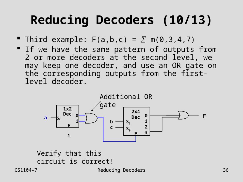
CS1104-7 Reducing Decoders 36
Reducing Decoders (10/13)
Third example: F(a,b,c) = m(0,3,4,7) If we have the same pattern of outputs from 2 or
more decoders at the second level, we may keep one decoder, and use an OR gate on the corresponding outputs from the first-level decoder.
F2x4Dec
S1
S0
0123E
bc
1x2Dec
S01
E
a
1
Additional OR gate
Verify that this circuit is correct!
CS1104-7 Reducing Decoders 37
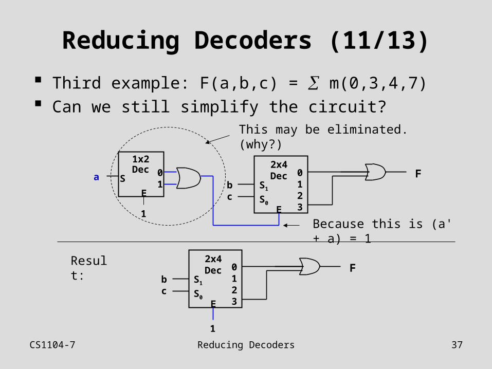
Reducing Decoders (11/13)
Third example: F(a,b,c) = m(0,3,4,7) Can we still simplify the circuit?
F2x4Dec
S1
S0
0123E
bc
1x2Dec
S01
E
a
1
This may be eliminated. (why?)
F2x4Dec
S1
S0
0123E
bc
1
Because this is (a' + a) = 1
Result:
CS1104-7 Reducing Decoders 38
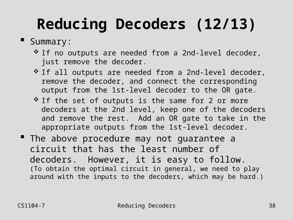
Reducing Decoders (12/13) Summary:
If no outputs are needed from a 2nd-level decoder, just remove the decoder.
If all outputs are needed from a 2nd-level decoder, remove the decoder, and connect the corresponding output from the 1st-level decoder to the OR gate.
If the set of outputs is the same for 2 or more decoders at the 2nd level, keep one of the decoders and remove the rest. Add an OR gate to take in the appropriate outputs from the 1st-level decoder.
The above procedure may not guarantee a circuit that has the least number of decoders. However, it is easy to follow. (To obtain the optimal circuit in general, we need to play around with the inputs to the decoders, which may be hard.)
CS1104-7 Reducing Decoders 39
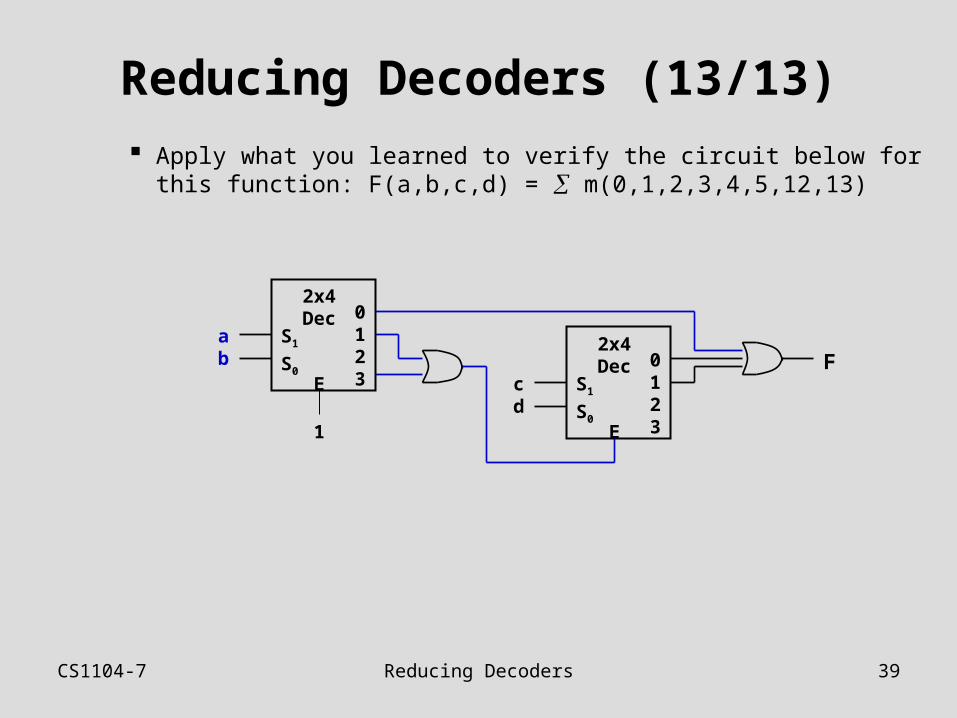
Reducing Decoders (13/13)
Apply what you learned to verify the circuit below for this function: F(a,b,c,d) = m(0,1,2,3,4,5,12,13)
F2x4Dec
S1
S0
0123E
cd
1
2x4Dec
S1
S0
0123E
ab
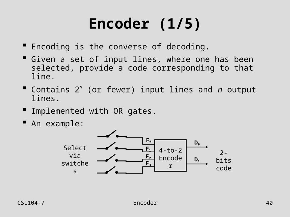
CS1104-7 Encoder 40
Encoder (1/5)
Encoding is the converse of decoding.
Given a set of input lines, where one has been selected, provide a code corresponding to that line.
Contains 2n (or fewer) input lines and n output lines.
Implemented with OR gates.
An example:
4-to-2 Encoder
F0
F1
F2
F3
D0
D1
Select via switches 2-bits
code
CS1104-7 Encoder 41
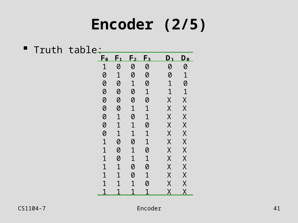
Encoder (2/5)
Truth table:F0 F1 F2 F3 D1 D0
1 0 0 0 0 00 1 0 0 0 10 0 1 0 1 00 0 0 1 1 10 0 0 0 X X0 0 1 1 X X0 1 0 1 X X0 1 1 0 X X0 1 1 1 X X1 0 0 1 X X1 0 1 0 X X1 0 1 1 X X1 1 0 0 X X1 1 0 1 X X1 1 1 0 X X1 1 1 1 X X
CS1104-7 Encoder 42
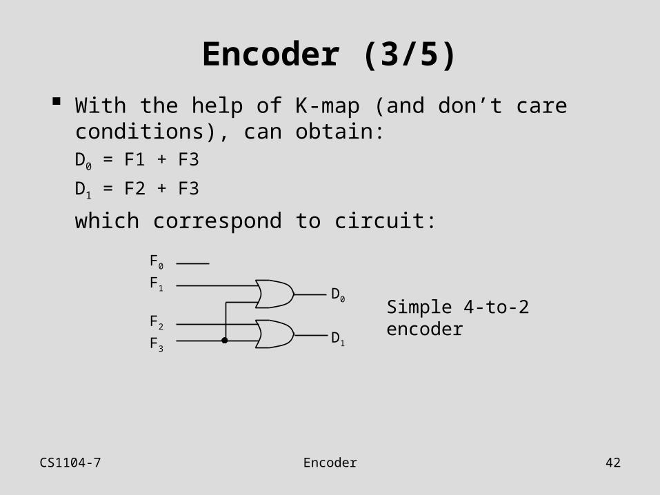
Encoder (3/5) With the help of K-map (and don’t care conditions),
can obtain:D0 = F1 + F3
D1 = F2 + F3
which correspond to circuit:
F0
F1
F2
F3D1
D0Simple 4-to-2 encoder
CS1104-7 Encoder 43
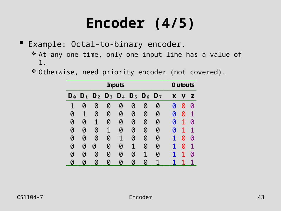
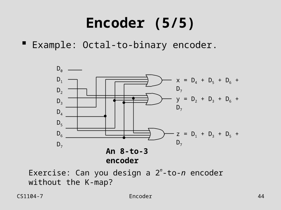
Encoder (4/5) Example: Octal-to-binary encoder.
At any one time, only one input line has a value of 1. Otherwise, need priority encoder (not covered).
Inputs Outputs
D0 D1 D2 D3 D4 D5 D6 D7 x y z
1 0 0 0 0 0 0 0 0 0 00 1 0 0 0 0 0 0 0 0 10 0 1 0 0 0 0 0 0 1 00 0 0 1 0 0 0 0 0 1 10 0 0 0 1 0 0 0 1 0 00 0 0 0 0 1 0 0 1 0 10 0 0 0 0 0 1 0 1 1 00 0 0 0 0 0 0 1 1 1 1
CS1104-7 Encoder 44
Encoder (5/5) Example: Octal-to-binary encoder.
Exercise: Can you design a 2n-to-n encoder without the K-map?
An 8-to-3 encoder
D0
D1
D2
D3
D4
D5
D6
D7
z = D1 + D3 + D5 + D7
y = D2 + D3 + D6 + D7
x = D4 + D5 + D6 + D7
CS1104-7 Demultiplexer 45
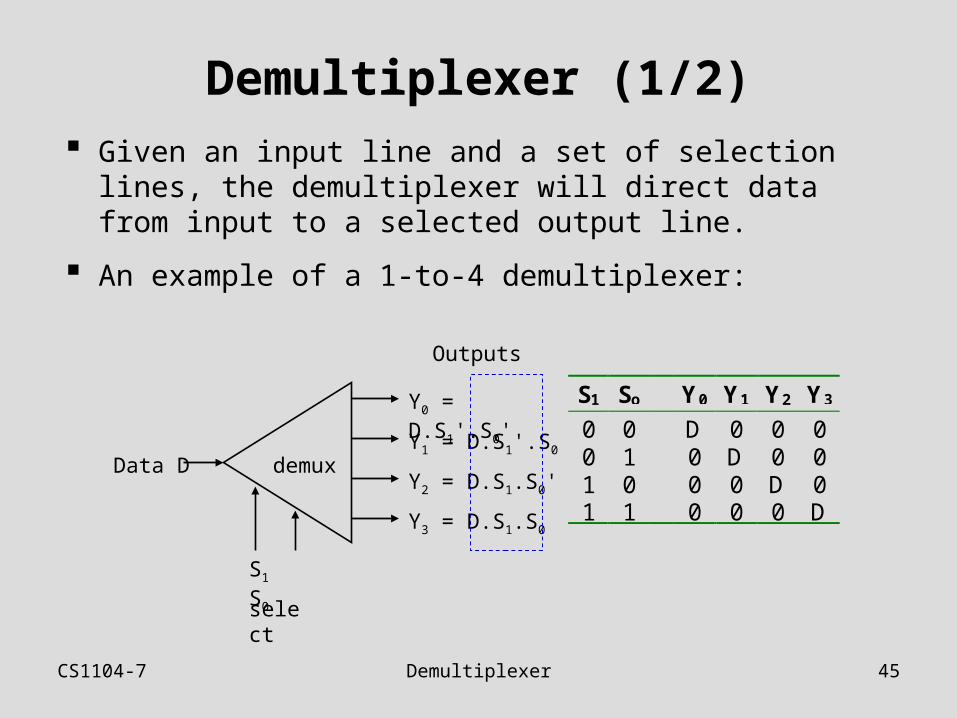
Demultiplexer (1/2) Given an input line and a set of selection lines, the
demultiplexer will direct data from input to a selected output line.
An example of a 1-to-4 demultiplexer:
S1 So Y0 Y1 Y2 Y3
0 0 D 0 0 00 1 0 D 0 01 0 0 0 D 01 1 0 0 0 D
demuxData D
Outputs
select
S1 S0
Y0 = D.S1'.S0'
Y1 = D.S1'.S0
Y2 = D.S1.S0'
Y3 = D.S1.S0
CS1104-7 Demultiplexer 46
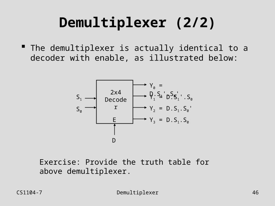
Demultiplexer (2/2)
The demultiplexer is actually identical to a decoder with enable, as illustrated below:
Exercise: Provide the truth table for above demultiplexer.
2x4 Decoder
D
S1
S0
Y0 = D.S1'.S0'
Y1 = D.S1'.S0
Y2 = D.S1.S0'
Y3 = D.S1.S0E
CS1104-7 Multiplexer 47
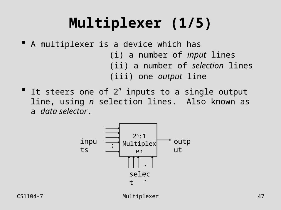
Multiplexer (1/5) A multiplexer is a device which has (i) a number of input lines (ii) a number of selection lines (iii) one output line
It steers one of 2n inputs to a single output line, using n selection lines. Also known as a data selector.
2n:1Multiplexer outputinputs
:
select
...
CS1104-7 Multiplexer 48
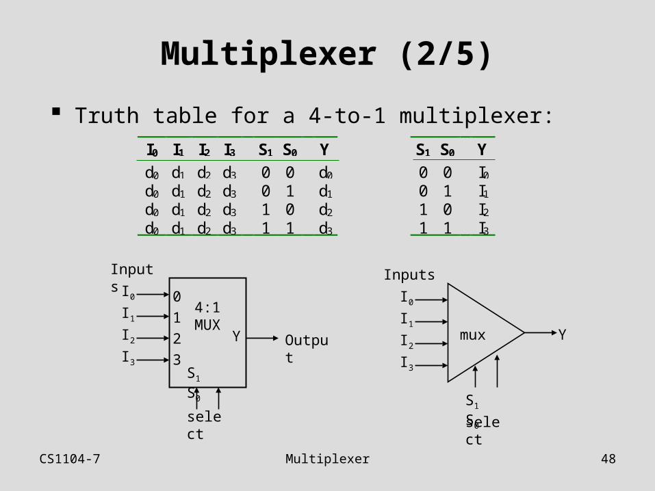
Multiplexer (2/5)
Truth table for a 4-to-1 multiplexer:
mux Y
Inputs
select
S1 S0
I0
I1
I2
I3
I0 I1 I2 I3 S1 S0 Y
d0 d1 d2 d3 0 0 d0
d0 d1 d2 d3 0 1 d1
d0 d1 d2 d3 1 0 d2
d0 d1 d2 d3 1 1 d3
S1 S0 Y
0 0 I0
0 1 I1
1 0 I2
1 1 I3
4:1MUX
Y
Inputs
select
S1 S0
I0
I1
I2
I3
0
1
2
3Output
CS1104-7 Multiplexer 49
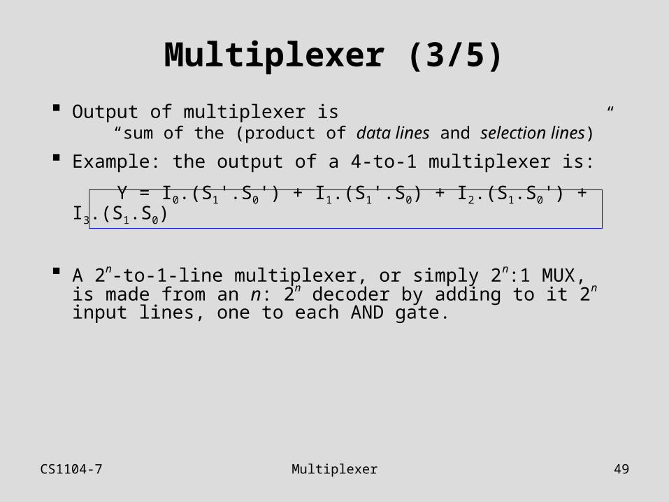
Multiplexer (3/5)
Output of multiplexer is “sum of the (product of data lines and selection lines)”
Example: the output of a 4-to-1 multiplexer is:
Y = I0.(S1'.S0') + I1.(S1'.S0) + I2.(S1.S0') + I3.(S1.S0)
A 2n-to-1-line multiplexer, or simply 2n:1 MUX, is made from an n: 2n decoder by adding to it 2n input lines, one to each AND gate.
CS1104-7 Multiplexer 50
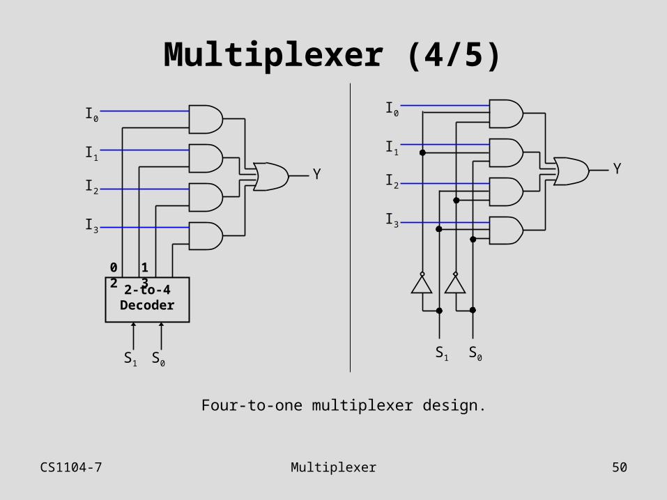
Multiplexer (4/5)
Four-to-one multiplexer design.
S1 S0
0 1 2 3
2-to-4 Decoder
I0
I1
I2
I3
Y
S1 S0
I0
I1
I2
I3
Y
CS1104-7 Multiplexer 51
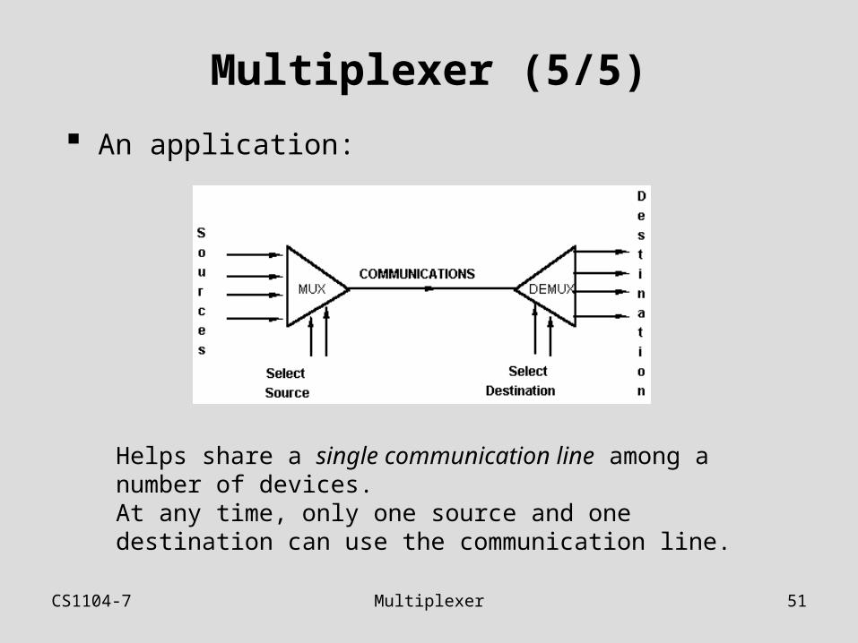
Multiplexer (5/5)
An application:
Helps share a single communication line among a number of devices.At any time, only one source and one destination can use the communication line.
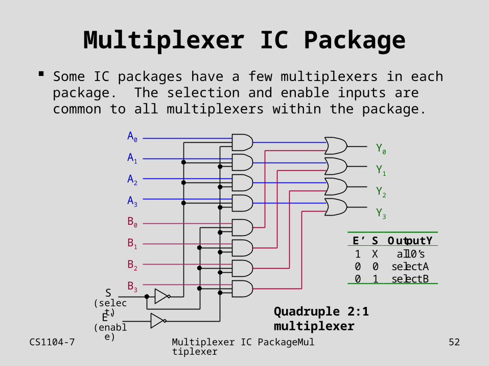
CS1104-7 Multiplexer IC PackageMultiplexer 52
Multiplexer IC Package Some IC packages have a few multiplexers in each
package. The selection and enable inputs are common to all multiplexers within the package.
S (select)
A0
A1
A2
A3
B0
B1
B2
B3
E' (enable)
Y0
Y1
Y2
Y3
E’ S Output Y1 X all 0’s0 0 select A0 1 select B
Quadruple 2:1 multiplexer
CS1104-7 Larger Multiplexers 53
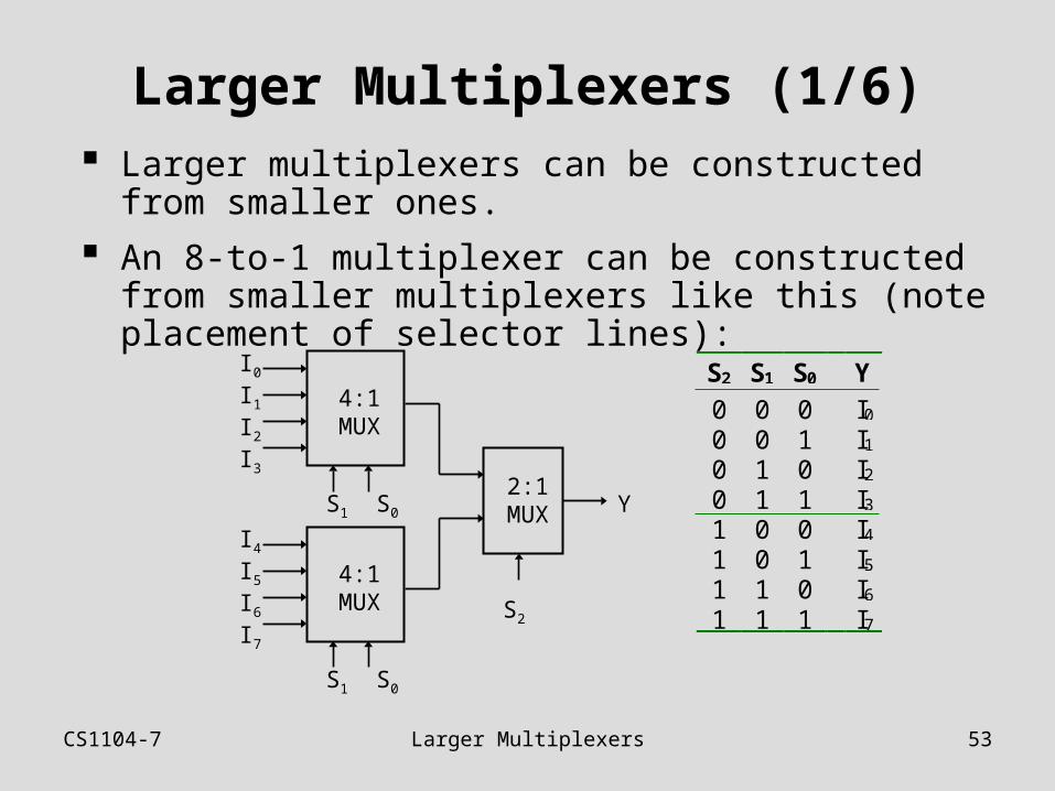
Larger Multiplexers (1/6) Larger multiplexers can be constructed from smaller
ones.
An 8-to-1 multiplexer can be constructed from smaller multiplexers like this (note placement of selector lines):
4:1 MUX
I0
I1
I2
I3
S1 S0
4:1 MUX
I4
I5
I6
I7
S1 S0
2:1 MUX
S2
Y
S2 S1 S0 Y
0 0 0 I0
0 0 1 I1
0 1 0 I2
0 1 1 I3
1 0 0 I4
1 0 1 I5
1 1 0 I6
1 1 1 I7
CS1104-7 Larger Multiplexers 54
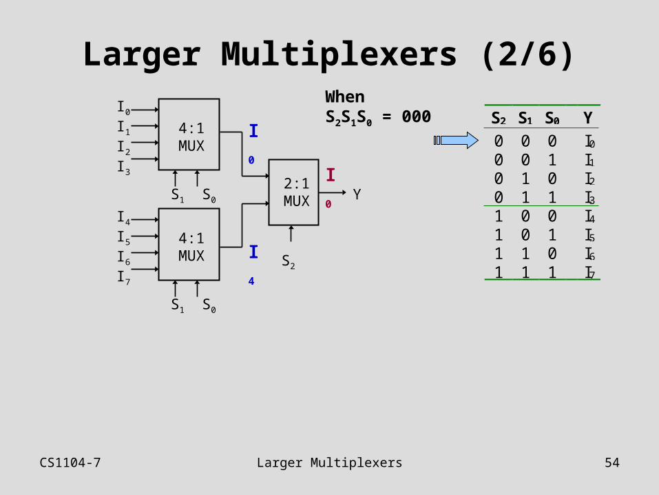
Larger Multiplexers (2/6)
4:1 MUX
I0
I1
I2
I3
S1 S0
4:1 MUX
I4
I5
I6
I7
S1 S0
2:1 MUX
S2
Y
I0
I4
I0
S2 S1 S0 Y
0 0 0 I0
0 0 1 I1
0 1 0 I2
0 1 1 I3
1 0 0 I4
1 0 1 I5
1 1 0 I6
1 1 1 I7
When S2S1S0 = 000
CS1104-7 Larger Multiplexers 55
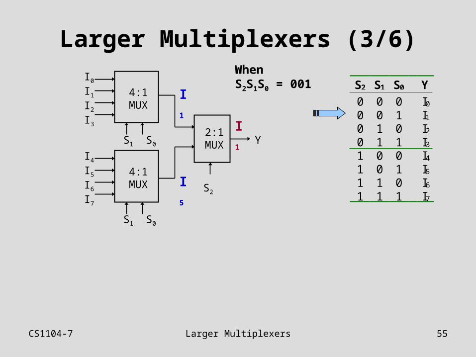
Larger Multiplexers (3/6)
4:1 MUX
I0
I1
I2
I3
S1 S0
4:1 MUX
I4
I5
I6
I7
S1 S0
2:1 MUX
S2
Y
I1
I5
I1
S2 S1 S0 Y
0 0 0 I0
0 0 1 I1
0 1 0 I2
0 1 1 I3
1 0 0 I4
1 0 1 I5
1 1 0 I6
1 1 1 I7
When S2S1S0 = 001
CS1104-7 Larger Multiplexers 56
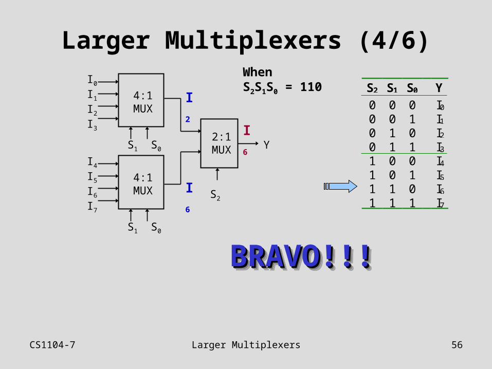
Larger Multiplexers (4/6)
4:1 MUX
I0
I1
I2
I3
S1 S0
4:1 MUX
I4
I5
I6
I7
S1 S0
2:1 MUX
S2
Y
I2
I6
I6
S2 S1 S0 Y
0 0 0 I0
0 0 1 I1
0 1 0 I2
0 1 1 I3
1 0 0 I4
1 0 1 I5
1 1 0 I6
1 1 1 I7
When S2S1S0 = 110
BRAVO!!!BRAVO!!!BRAVO!!!BRAVO!!!
CS1104-7 Larger Multiplexers 57
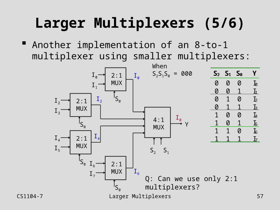
Larger Multiplexers (5/6) Another implementation of an 8-to-1 multiplexer using
smaller multiplexers:
YI0
When S2S1S0 = 000
4:1 MUX
S2 S1
I0
I1
2:1 MUX
S0I2
I3
2:1 MUX
S0
I4
I5
2:1 MUX
S0 I6
I7
2:1 MUX
S0
I0
I4
I2
I6
Q: Can we use only 2:1 multiplexers?
S2 S1 S0 Y
0 0 0 I0
0 0 1 I1
0 1 0 I2
0 1 1 I3
1 0 0 I4
1 0 1 I5
1 1 0 I6
1 1 1 I7
CS1104-7 Larger Multiplexers 58
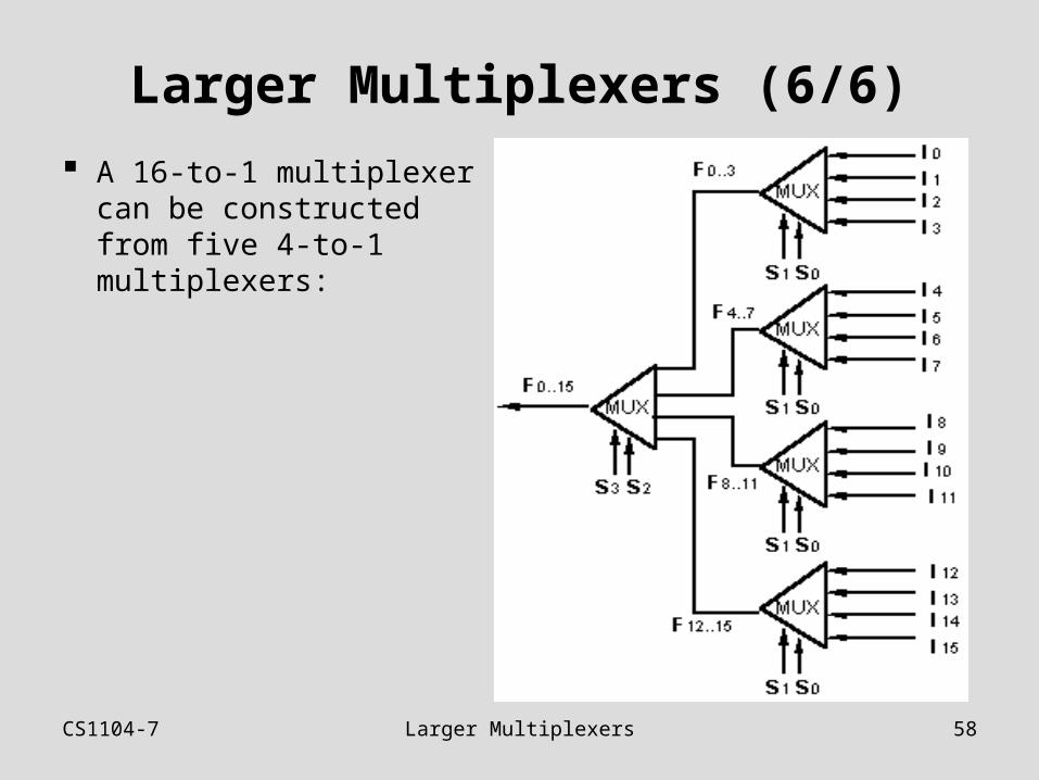
Larger Multiplexers (6/6)
A 16-to-1 multiplexer can be constructed from five 4-to-1 multiplexers:
CS1104-7 Standard MSI Multiplexer 59
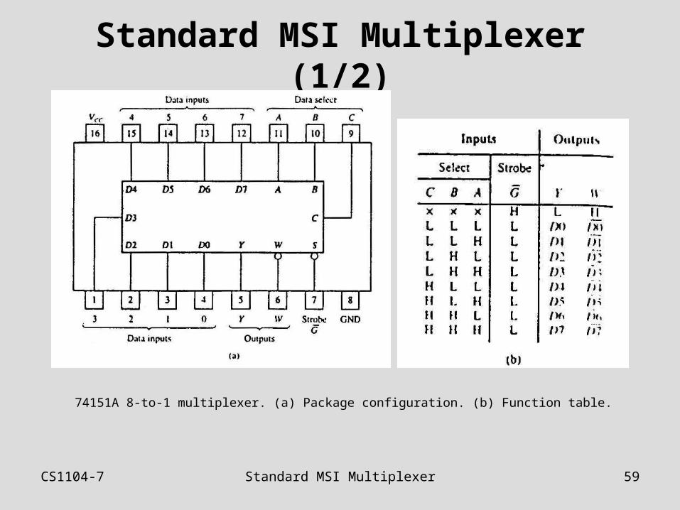
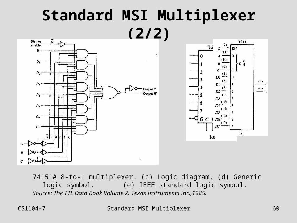
Standard MSI Multiplexer (1/2)
74151A 8-to-1 multiplexer. (a) Package configuration. (b) Function table.
CS1104-7 Standard MSI Multiplexer 60
Standard MSI Multiplexer (2/2)
74151A 8-to-1 multiplexer. (c) Logic diagram. (d) Generic logic symbol. (e) IEEE standard logic symbol.
Source: The TTL Data Book Volume 2. Texas Instruments Inc.,1985.
CS1104-7 Multiplexers: Implementing Functions
61
Multiplexers: Implementing Functions (1/3)
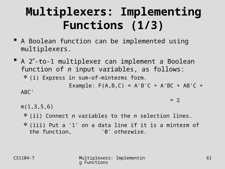
A Boolean function can be implemented using multiplexers.
A 2n-to-1 multiplexer can implement a Boolean function of n input variables, as follows: (i) Express in sum-of-minterms form.
Example: F(A,B,C) = A'B'C + A'BC + AB'C + ABC'
= m(1,3,5,6)
(ii) Connect n variables to the n selection lines.
(iii) Put a '1' on a data line if it is a minterm of the function, '0' otherwise.
CS1104-7 Multiplexers: Implementing Functions
62
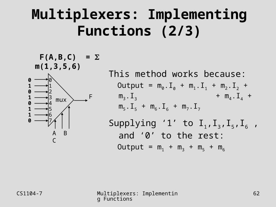
Multiplexers: Implementing Functions (2/3)
This method works because: Output = m0.I0 + m1.I1 + m2.I2 + m3.I3
+ m4.I4 + m5.I5 + m6.I6 + m7.I7
Supplying ‘1’ to I1,I3,I5,I6 , and ‘0’ to
the rest: Output = m1 + m3 + m5 + m6
F(A,B,C) = m(1,3,5,6)
mux
A B C
01234567
01010110
F
CS1104-7 Multiplexers: Implementing Functions
63
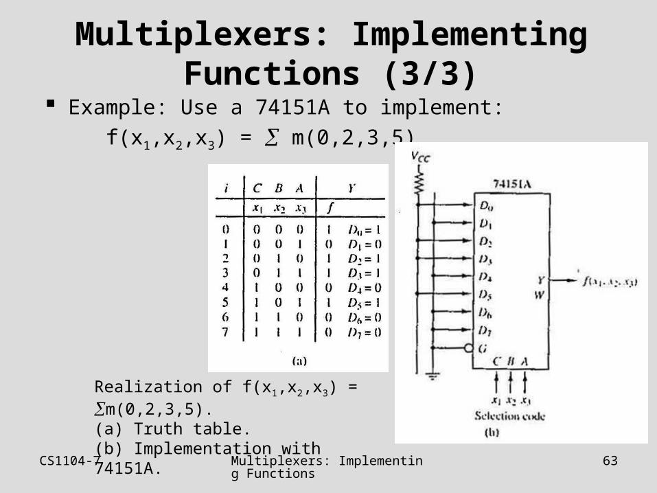
Multiplexers: Implementing Functions (3/3)
Example: Use a 74151A to implement:
f(x1,x2,x3) = m(0,2,3,5)
Realization of f(x1,x2,x3) = m(0,2,3,5).(a) Truth table. (b) Implementation with 74151A.
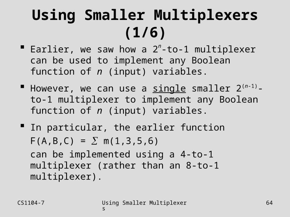
CS1104-7 Using Smaller Multiplexers 64
Using Smaller Multiplexers (1/6)
Earlier, we saw how a 2n-to-1 multiplexer can be used to implement any Boolean function of n (input) variables.
However, we can use a single smaller 2(n-1)-to-1 multiplexer to implement any Boolean function of n (input) variables.
In particular, the earlier function
F(A,B,C) = m(1,3,5,6)
can be implemented using a 4-to-1 multiplexer (rather than an 8-to-1 multiplexer).
CS1104-7 Using Smaller Multiplexers 65
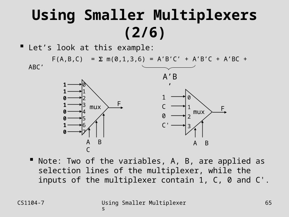
Using Smaller Multiplexers (2/6)
Note: Two of the variables, A, B, are applied as selection lines of the multiplexer, while the inputs of the multiplexer contain 1, C, 0 and C'.
mux
A B C
01234567
11010010
Fmux
A B
0
1
2
3
1
C
0
C'
F
Let’s look at this example:
F(A,B,C) = m(0,1,3,6) = A’B’C’ + A’B’C + A’BC + ABC’
A’B’
CS1104-7 Using Smaller Multiplexers 66
Using Smaller Multiplexers (3/6)
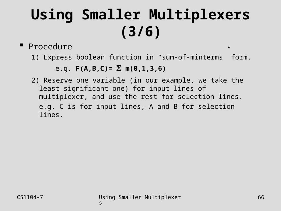
Procedure1) Express boolean function in “sum-of-minterms” form.
e.g. F(A,B,C)= m(0,1,3,6)
2) Reserve one variable (in our example, we take the least significant one) for input lines of multiplexer, and use the rest for selection lines.
e.g. C is for input lines, A and B for selection lines.
CS1104-7 Using Smaller Multiplexers 67
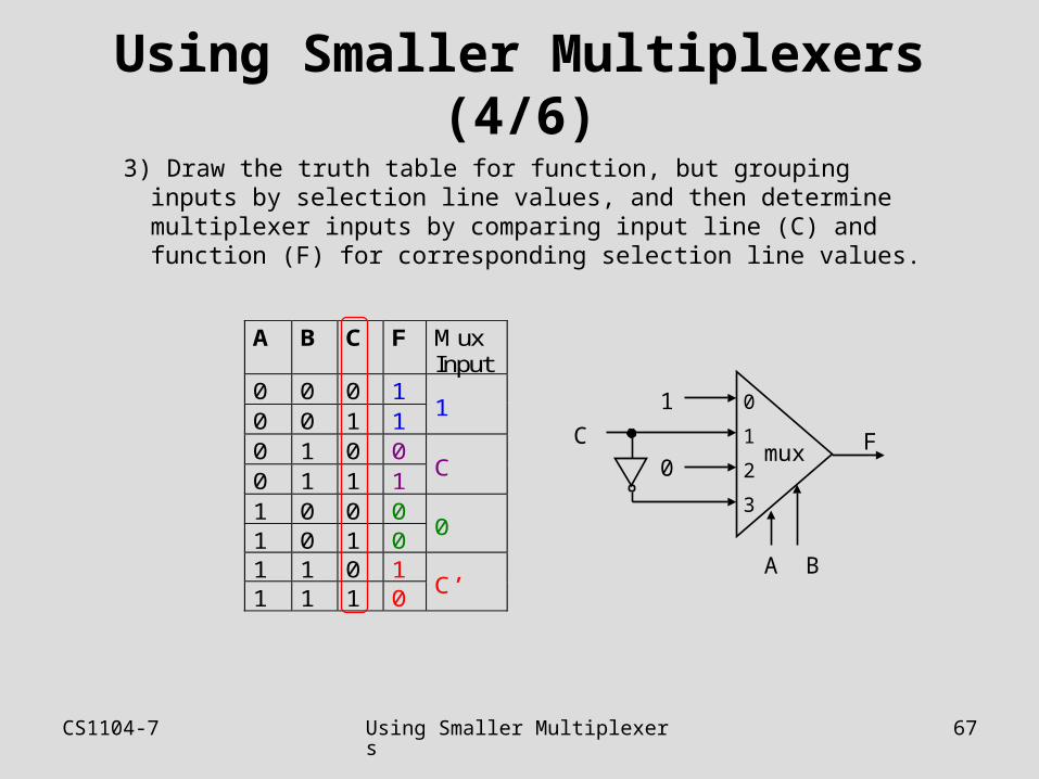
Using Smaller Multiplexers (4/6)
A B C F MuxInput
0 0 0 10 0 1 1
1
0 1 0 00 1 1 1
C
1 0 0 01 0 1 0
0
1 1 0 11 1 1 0
C’
3) Draw the truth table for function, but grouping inputs by selection line values, and then determine multiplexer inputs by comparing input line (C) and function (F) for corresponding selection line values.
mux
A B
0
1
2
3
1
0 FC
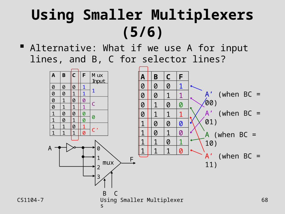
CS1104-7 Using Smaller Multiplexers 68
Using Smaller Multiplexers (5/6)
A B C F MuxInput
0 0 0 10 0 1 1
1
0 1 0 00 1 1 1
C
1 0 0 01 0 1 0
0
1 1 0 11 1 1 0
C’
Alternative: What if we use A for input lines, and B, C for selector lines?
A B C F0 0 0 10 0 1 10 1 0 00 1 1 11 0 0 01 0 1 01 1 0 11 1 1 0
A’ (when BC = 00)
A’ (when BC = 01)
A (when BC = 10)
A’ (when BC = 11)mux
B C
0
1
2
3
A
F
CS1104-7 Using Smaller Multiplexers 69
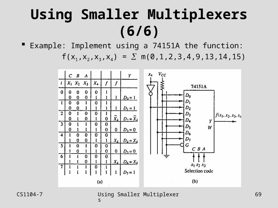
Using Smaller Multiplexers (6/6)
Example: Implement using a 74151A the function:
f(x1,x2,x3,x4) = m(0,1,2,3,4,9,13,14,15)

CS1103
End of file