Embed Size (px)
Citation preview
CSC 322: FPGAs and Verilog
Based on slides from John NestorLafayette College
Easton, Pennsylvania 18042
CSC322 Fall 2015 Computer Organization Lab 2
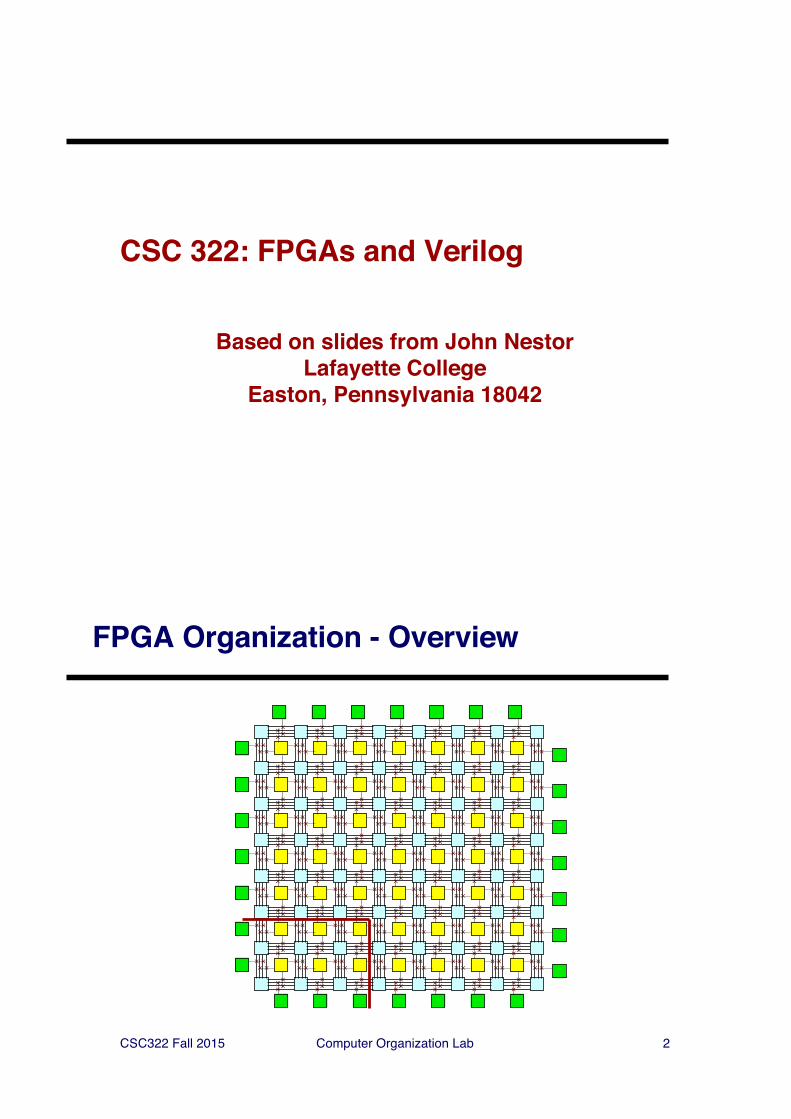
FPGA Organization - Overview
CSC322 Fall 2015 Computer Organization Lab 3
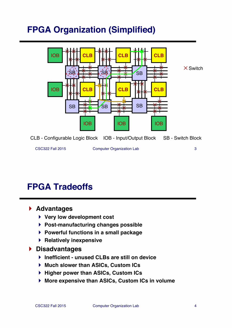
FPGA Organization (Simplified)
CLB
SB
SB
SB
CLB
CLBCLB
SB
CLB
CLB
IOB - Input/Output Block
IOB
SB
SB
IOB
IOBIOB IOB
CLB - Configurable Logic Block SB - Switch Block
Switch
CSC322 Fall 2015 Computer Organization Lab 4
FPGA Tradeoffs
} Advantages} Very low development cost} Post-manufacturing changes possible} Powerful functions in a small package} Relatively inexpensive
} Disadvantages} Inefficient - unused CLBs are still on device} Much slower than ASICs, Custom ICs} Higher power than ASICs, Custom ICs} More expensive than ASICs, Custom ICs in volume
CSC322 Fall 2015 Computer Organization Lab 5
Verilog Overview
} Important Points About Verilog} The module construct} Combinational Logic} Parameters} Module Instantiation} Sequential Logic} Finite State Machines
CSC322 Fall 2015 Computer Organization Lab 6
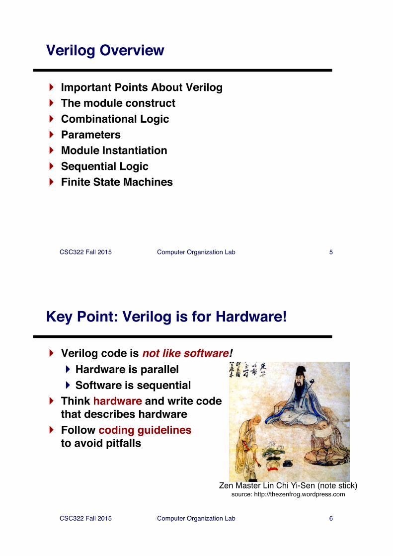
Key Point: Verilog is for Hardware!
} Verilog code is not like software!} Hardware is parallel} Software is sequential
} Think hardware and write code that describes hardware
} Follow coding guidelinesto avoid pitfalls
Zen Master Lin Chi Yi-Sen (note stick)source: http://thezenfrog.wordpress.com
CSC322 Fall 2015 Computer Organization Lab 7
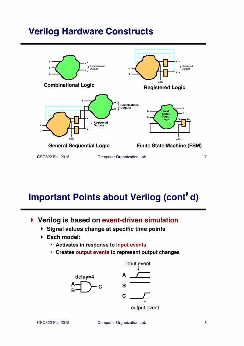
Verilog Hardware Constructs
a
b
c
x
yCombinationalOutputs
Combinational Logic
a
b
x
y
clk
RegisteredOutputs
Registered Logic
av
wCombinationalOutputs
x
y
RegisteredOutputsa
b
x
y
clk
General Sequential Logic
avwNext
State / Output Logic psns
b
clk
Finite State Machine (FSM)
CSC322 Fall 2015 Computer Organization Lab 8
Important Points about Verilog (cont�d)
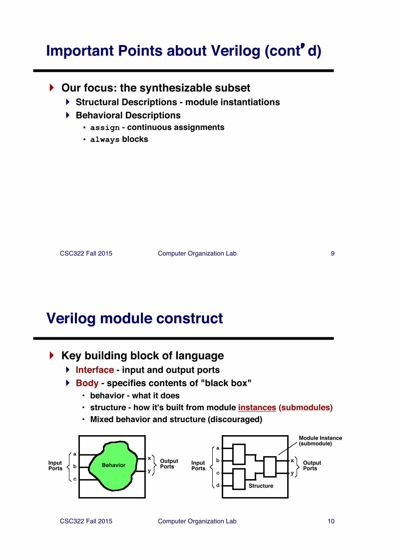
} Verilog is based on event-driven simulation} Signal values change at specific time points} Each model:
• Activates in response to input events• Creates output events to represent output changes
AB C
A
B
C
delay=4
input event
output event
CSC322 Fall 2015 Computer Organization Lab 9
Important Points about Verilog (cont�d)
} Our focus: the synthesizable subset} Structural Descriptions - module instantiations} Behavioral Descriptions
• assign - continuous assignments• always blocks
CSC322 Fall 2015 Computer Organization Lab 10
Verilog module construct
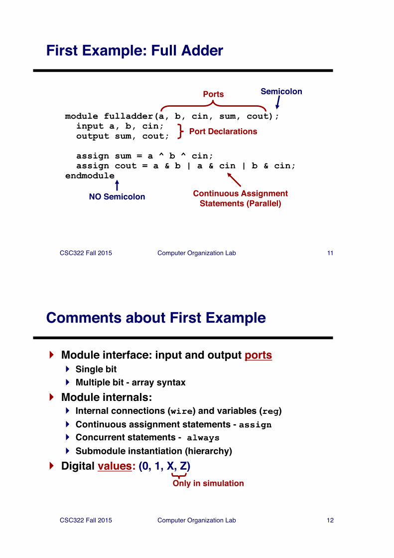
} Key building block of language} Interface - input and output ports} Body - specifies contents of "black box"
• behavior - what it does• structure - how it's built from module instances (submodules)• Mixed behavior and structure (discouraged)
a
b
c
x
y
OutputPortsInput
Ports Behavior
a
b
c
x
y
OutputPorts
InputPorts
Structured
Module Instance(submodule)
CSC322 Fall 2015 Computer Organization Lab 11
First Example: Full Adder
module fulladder(a, b, cin, sum, cout);input a, b, cin;output sum, cout;
assign sum = a ^ b ^ cin;assign cout = a & b | a & cin | b & cin;
endmodule
Ports
Port Declarations
Semicolon
NO Semicolon Continuous AssignmentStatements (Parallel)
CSC322 Fall 2015 Computer Organization Lab 12
Comments about First Example
} Module interface: input and output ports} Single bit} Multiple bit - array syntax
} Module internals:} Internal connections (wire) and variables (reg)} Continuous assignment statements - assign} Concurrent statements - always} Submodule instantiation (hierarchy)
} Digital values: (0, 1, X, Z)Only in simulation
CSC322 Fall 2015 Computer Organization Lab 13
Example: 7-Segment Decoder
SymbolicConstants
Port Declarations
Variable (reg) Declaration
module seven_seg(data, segments);input [3:0] data;output [6:0] segments;
reg [6:0] segments;
// Output patterns: abc_defgparameter BLANK = 7'b111_1111;parameter ZERO = 7'b000_0001;parameter ONE = 7'b100_1111;parameter TWO = 7'b001_0010;parameter THREE = 7'b000_0110;parameter FOUR = 7'b100_1100;parameter FIVE = 7'b010_0100;parameter SIX = 7'b010_0000;parameter SEVEN = 7'b000_1111;parameter EIGHT = 7'b000_0000;parameter NINE = 7'b000_0100;
CSC322 Fall 2015 Computer Organization Lab 14
Example: 7-Segment Decoder Part 2
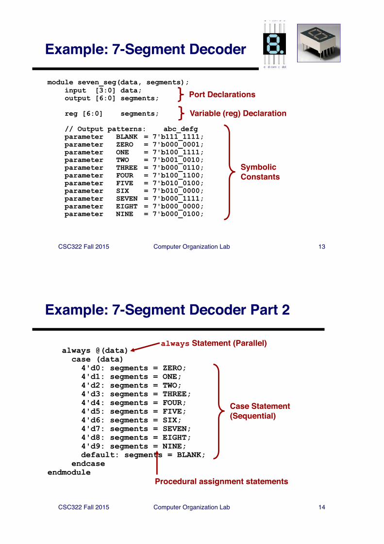
always @(data)case (data)4'd0: segments = ZERO;4'd1: segments = ONE;4'd2: segments = TWO;4'd3: segments = THREE;4'd4: segments = FOUR;4'd5: segments = FIVE;4'd6: segments = SIX;4'd7: segments = SEVEN;4'd8: segments = EIGHT;4'd9: segments = NINE;default: segments = BLANK;
endcaseendmodule
always Statement (Parallel)
Case Statement(Sequential)
Procedural assignment statements
CSC322 Fall 2015 Computer Organization Lab 15
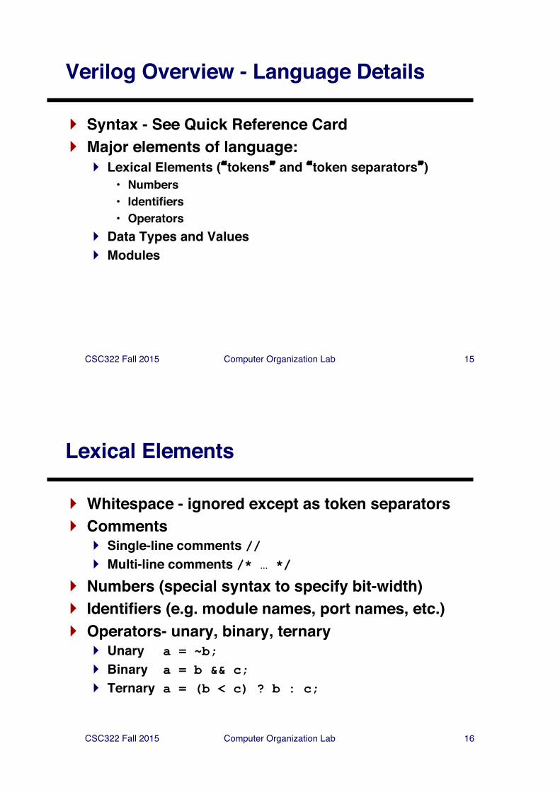
Verilog Overview - Language Details
} Syntax - See Quick Reference Card} Major elements of language:
} Lexical Elements (�tokens� and �token separators�)• Numbers• Identifiers• Operators
} Data Types and Values} Modules
CSC322 Fall 2015 Computer Organization Lab 16
Lexical Elements
} Whitespace - ignored except as token separators } Comments
} Single-line comments //} Multi-line comments /* … */
} Numbers (special syntax to specify bit-width)} Identifiers (e.g. module names, port names, etc.)} Operators- unary, binary, ternary
} Unary a = ~b;} Binary a = b && c;} Ternary a = (b < c) ? b : c;
CSC322 Fall 2015 Computer Organization Lab 17
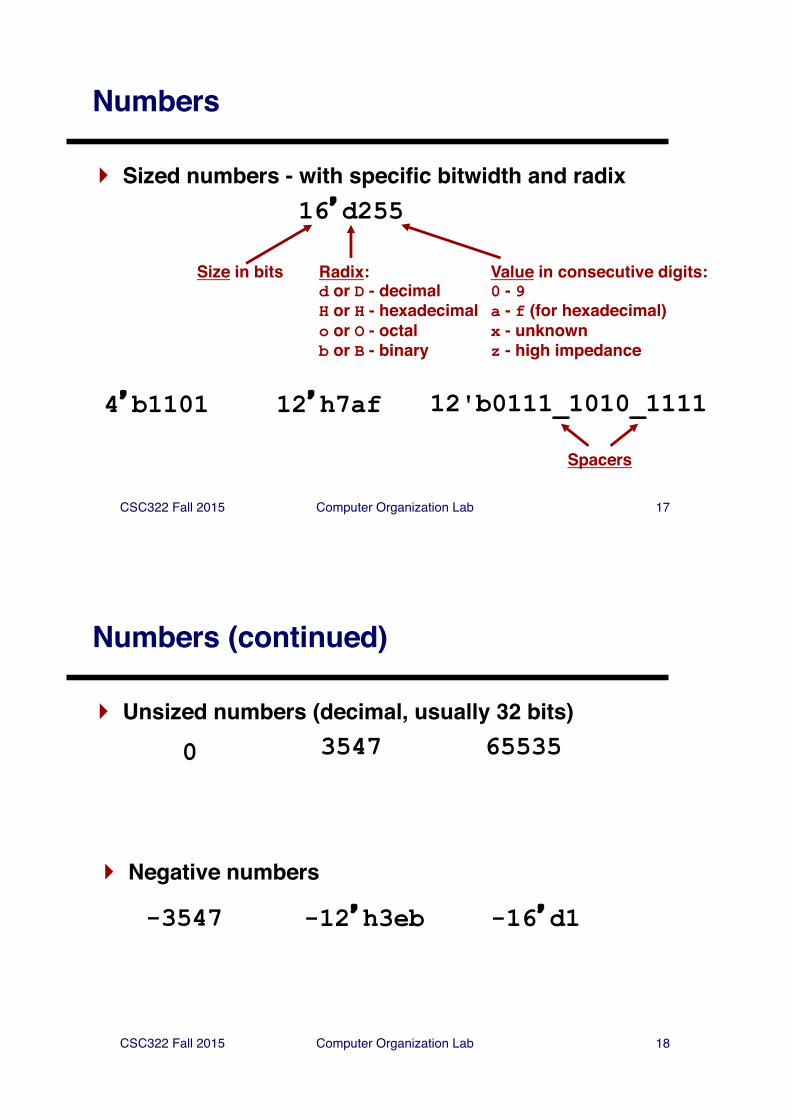
Numbers
} Sized numbers - with specific bitwidth and radix16�d255
12�h7af4�b1101
Size in bits Radix:d or D - decimalH or H - hexadecimalo or O - octalb or B - binary
Value in consecutive digits:0 - 9a - f (for hexadecimal)x - unknownz - high impedance
12'b0111_1010_1111
Spacers
CSC322 Fall 2015 Computer Organization Lab 18
Numbers (continued)
} Unsized numbers (decimal, usually 32 bits)
} Negative numbers
3547 655350
-3547 -12�h3eb -16�d1
CSC322 Fall 2015 Computer Organization Lab 19
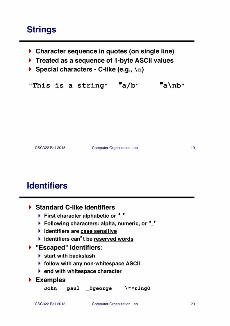
Strings
} Character sequence in quotes (on single line)} Treated as a sequence of 1-byte ASCII values} Special characters - C-like (e.g., \n)
"This is a string" �a/b" �a\nb"
CSC322 Fall 2015 Computer Organization Lab 20
Identifiers
} Standard C-like identifiers} First character alphabetic or �_�} Following characters: alpha, numeric, or �_�} Identifiers are case sensitive} Identifiers can�t be reserved words
} "Escaped" identifiers:} start with backslash} follow with any non-whitespace ASCII} end with whitespace character
} ExamplesJohn paul _0george \**r1ng0
CSC322 Fall 2015 Computer Organization Lab 21
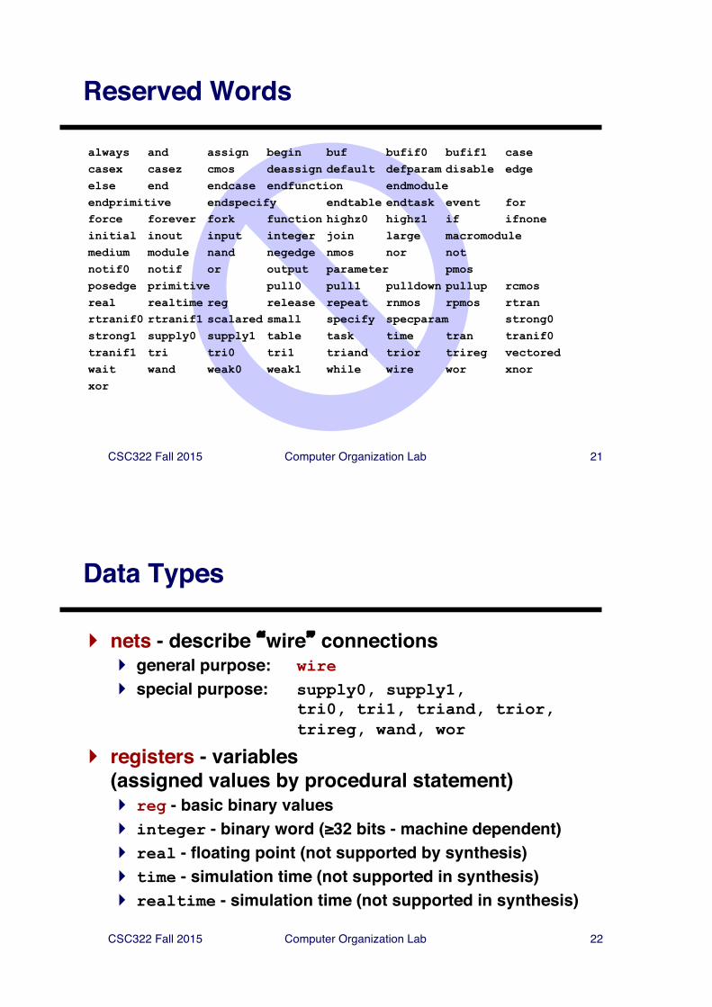
Reserved Words
always and assign begin buf bufif0 bufif1 casecasex casez cmos deassign default defparam disable edgeelse end endcase endfunction endmoduleendprimitive endspecify endtable endtask event forforce forever fork function highz0 highz1 if ifnoneinitial inout input integer join large macromodulemedium module nand negedge nmos nor not notif0 notif or output parameter pmosposedge primitive pull0 pull1 pulldown pullup rcmosreal realtime reg release repeat rnmos rpmos rtranrtranif0 rtranif1 scalared small specify specparam strong0strong1 supply0 supply1 table task time tran tranif0tranif1 tri tri0 tri1 triand trior trireg vectoredwait wand weak0 weak1 while wire wor xnorxor
CSC322 Fall 2015 Computer Organization Lab 22
Data Types
} nets - describe �wire� connections} general purpose: wire} special purpose: supply0, supply1,
tri0, tri1, triand, trior,trireg, wand, wor
} registers - variables (assigned values by procedural statement)} reg - basic binary values} integer - binary word (≥32 bits - machine dependent)} real - floating point (not supported by synthesis)} time - simulation time (not supported in synthesis)} realtime - simulation time (not supported in synthesis)
CSC322 Fall 2015 Computer Organization Lab 23
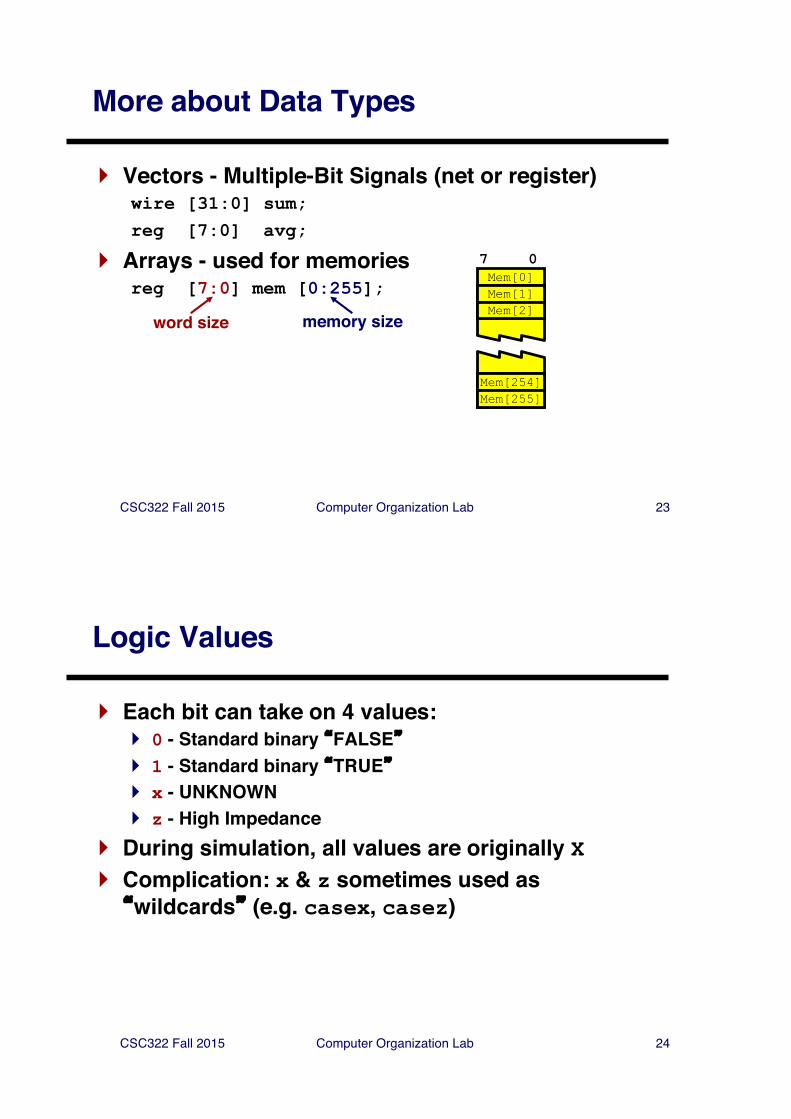
More about Data Types
} Vectors - Multiple-Bit Signals (net or register)wire [31:0] sum;reg [7:0] avg;
} Arrays - used for memoriesreg [7:0] mem [0:255];
word size memory size
Mem[0]7 0
Mem[1]Mem[2]
Mem[254]Mem[255]
CSC322 Fall 2015 Computer Organization Lab 24
Logic Values
} Each bit can take on 4 values:} 0 - Standard binary �FALSE�} 1 - Standard binary �TRUE�} x - UNKNOWN} z - High Impedance
} During simulation, all values are originally X} Complication: x & z sometimes used as �wildcards� (e.g. casex, casez)
CSC322 Fall 2015 Computer Organization Lab 25
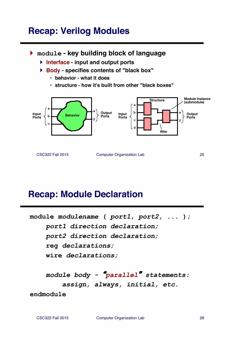
Recap: Verilog Modules
} module - key building block of language} Interface - input and output ports} Body - specifies contents of "black box"
• behavior - what it does• structure - how it's built from other "black boxes"
a
b
c
x
y
OutputPortsInput
Ports Behavior
a
b
c
x
y
OutputPorts
InputPorts
Structure
d
Module Instance(submodule)
Wire
CSC322 Fall 2015 Computer Organization Lab 26
Recap: Module Declaration
module modulename ( port1, port2, ... );port1 direction declaration;port2 direction declaration;reg declarations;wire declarations;
module body - �parallel� statements:assign, always, initial, etc.
endmodule
CSC322 Fall 2015 Computer Organization Lab 27
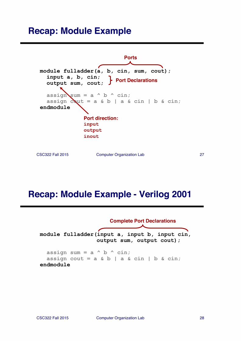
Recap: Module Example
module fulladder(a, b, cin, sum, cout);input a, b, cin;output sum, cout;
assign sum = a ^ b ^ cin;assign cout = a & b | a & cin | b & cin;
endmodule
Ports
Port Declarations
Port direction:inputoutputinout
CSC322 Fall 2015 Computer Organization Lab 28
Recap: Module Example - Verilog 2001
module fulladder(input a, input b, input cin, output sum, output cout);
assign sum = a ^ b ^ cin;assign cout = a & b | a & cin | b & cin;
endmodule
Complete Port Declarations
CSC322 Fall 2015 Computer Organization Lab 29
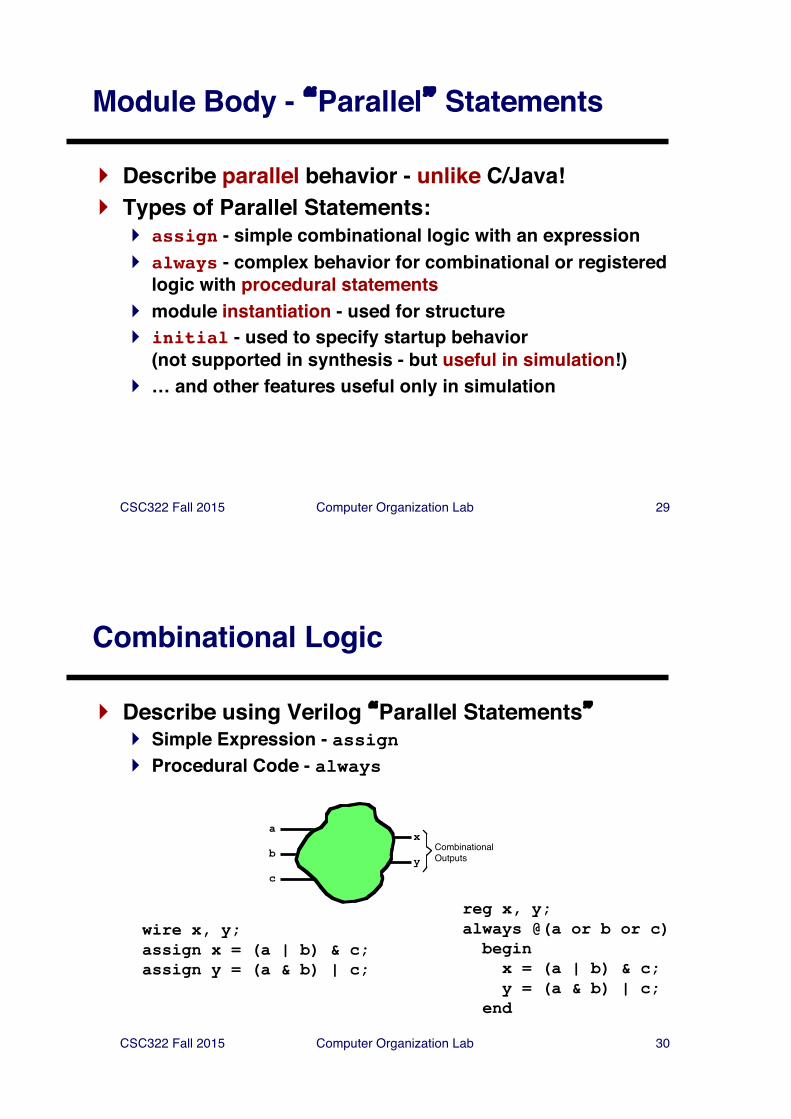
Module Body - �Parallel� Statements
} Describe parallel behavior - unlike C/Java!} Types of Parallel Statements:
} assign - simple combinational logic with an expression} always - complex behavior for combinational or registered
logic with procedural statements} module instantiation - used for structure} initial - used to specify startup behavior
(not supported in synthesis - but useful in simulation!)} … and other features useful only in simulation
CSC322 Fall 2015 Computer Organization Lab 30
Combinational Logic
} Describe using Verilog �Parallel Statements�} Simple Expression - assign} Procedural Code - always
a
b
c
x
yCombinationalOutputs
wire x, y;assign x = (a | b) & c;assign y = (a & b) | c;
reg x, y;always @(a or b or c)beginx = (a | b) & c;y = (a & b) | c;
end
CSC322 Fall 2015 Computer Organization Lab 31
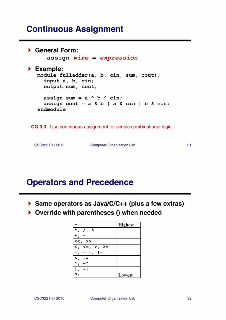
Continuous Assignment
} General Form:assign wire = expression
} Example:module fulladder(a, b, cin, sum, cout);
input a, b, cin;output sum, cout;
assign sum = a ^ b ^ cin;assign cout = a & b | a & cin | b & cin;
endmodule
CG 3.3: Use continuous assignment for simple combinational logic.
CSC322 Fall 2015 Computer Organization Lab 32
Operators and Precedence
} Same operators as Java/C/C++ (plus a few extras)} Override with parentheses () when needed
~ Highest*, /, %+, -<<, >><, <=, >, >==, = =, !=&, ~&^, ~^|, ~|?: Lowest
CSC322 Fall 2015 Computer Organization Lab 33
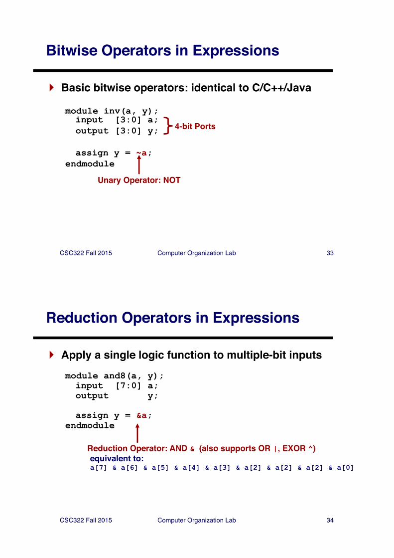
Bitwise Operators in Expressions
} Basic bitwise operators: identical to C/C++/Java
module inv(a, y);input [3:0] a;output [3:0] y;
assign y = ~a;endmodule
Unary Operator: NOT
4-bit Ports
CSC322 Fall 2015 Computer Organization Lab 34
Reduction Operators in Expressions
} Apply a single logic function to multiple-bit inputsmodule and8(a, y);input [7:0] a;output y;
assign y = &a;endmodule
Reduction Operator: AND & (also supports OR |, EXOR ^)equivalent to:a[7] & a[6] & a[5] & a[4] & a[3] & a[2] & a[2] & a[2] & a[0]
CSC322 Fall 2015 Computer Organization Lab 35
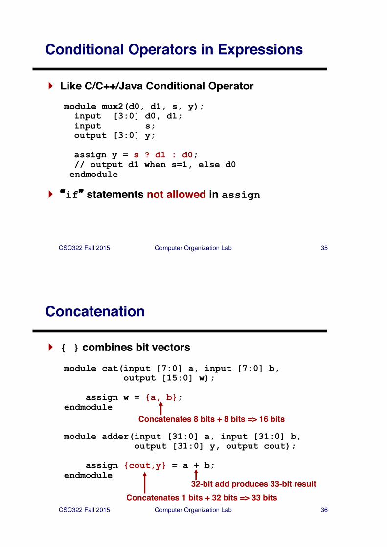
Conditional Operators in Expressions
} Like C/C++/Java Conditional Operatormodule mux2(d0, d1, s, y);input [3:0] d0, d1;input s;output [3:0] y;
assign y = s ? d1 : d0;// output d1 when s=1, else d0endmodule
} �if� statements not allowed in assign
CSC322 Fall 2015 Computer Organization Lab 36
Concatenation
} { } combines bit vectors
module cat(input [7:0] a, input [7:0] b,output [15:0] w);
assign w = {a, b};endmodule
module adder(input [31:0] a, input [31:0] b, output [31:0] y, output cout);
assign {cout,y} = a + b;endmodule
Concatenates 8 bits + 8 bits => 16 bits
Concatenates 1 bits + 32 bits => 33 bits32-bit add produces 33-bit result
CSC322 Fall 2015 Computer Organization Lab 37
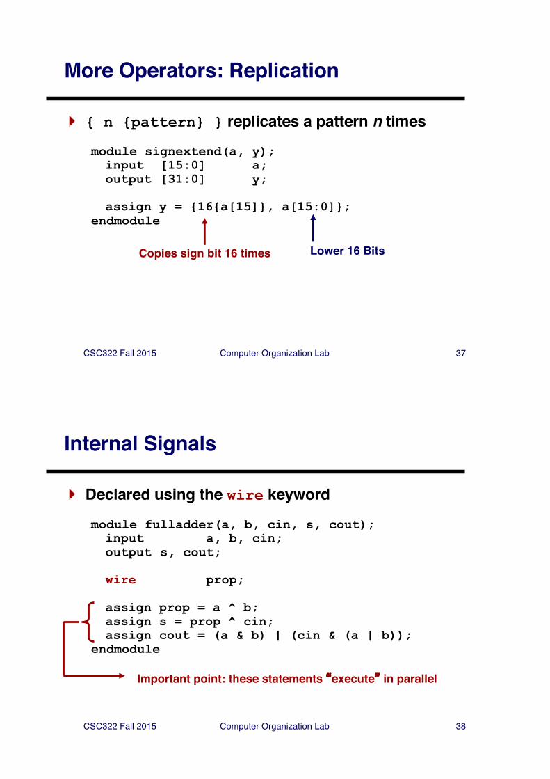
More Operators: Replication
} { n {pattern} } replicates a pattern n times
module signextend(a, y);input [15:0] a;output [31:0] y;
assign y = {16{a[15]}, a[15:0]};endmodule
Copies sign bit 16 times Lower 16 Bits
CSC322 Fall 2015 Computer Organization Lab 38
Internal Signals
} Declared using the wire keyword
module fulladder(a, b, cin, s, cout);input a, b, cin;output s, cout;
wire prop;
assign prop = a ^ b;assign s = prop ^ cin;assign cout = (a & b) | (cin & (a | b));
endmodule
Important point: these statements �execute� in parallel
CSC322 Fall 2015 Computer Organization Lab 39
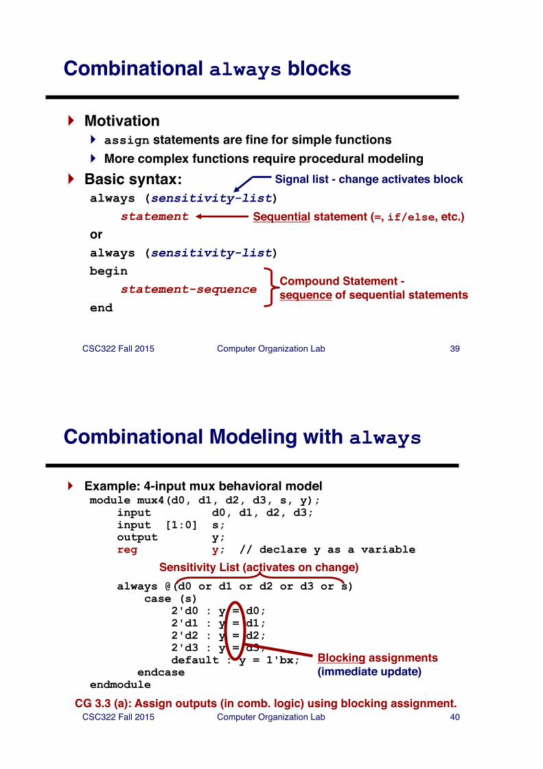
Combinational always blocks
} Motivation} assign statements are fine for simple functions} More complex functions require procedural modeling
} Basic syntax:always (sensitivity-list)
statementoralways (sensitivity-list)begin
statement-sequenceend
Signal list - change activates block
Sequential statement (=, if/else, etc.)
Compound Statement -sequence of sequential statements
CSC322 Fall 2015 Computer Organization Lab 40
Combinational Modeling with always
} Example: 4-input mux behavioral modelmodule mux4(d0, d1, d2, d3, s, y);
input d0, d1, d2, d3;input [1:0] s;output y;reg y; // declare y as a variable
always @(d0 or d1 or d2 or d3 or s)case (s)
2'd0 : y = d0;2'd1 : y = d1;2'd2 : y = d2;2'd3 : y = d3;default : y = 1'bx;
endcaseendmodule
Blocking assignments(immediate update)
Sensitivity List (activates on change)
CG 3.3 (a): Assign outputs (in comb. logic) using blocking assignment.
CSC322 Fall 2015 Computer Organization Lab 41
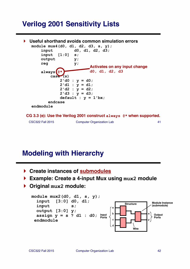
Verilog 2001 Sensitivity Lists
} Useful shorthand avoids common simulation errorsmodule mux4(d0, d1, d2, d3, s, y);
input d0, d1, d2, d3;input [1:0] s;output y;reg y;
always @*case (s)
2'd0 : y = d0;2'd1 : y = d1;2'd2 : y = d2;2'd3 : y = d3;default : y = 1'bx;
endcaseendmodule
Activates on any input changed0, d1, d2, d3
CG 3.3 (e): Use the Verilog 2001 construct always @* when supported.
CSC322 Fall 2015 Computer Organization Lab 42
Modeling with Hierarchy
} Create instances of submodules} Example: Create a 4-input Mux using mux2 module} Original mux2 module:
module mux2(d0, d1, s, y);input [3:0] d0, d1;input s;output [3:0] y;assign y = s ? d1 : d0;endmodule
a
b
c
x
y
OutputPorts
InputPorts
Structure
d
Module Instance(submodule)
Wire
CSC322 Fall 2015 Computer Organization Lab 43
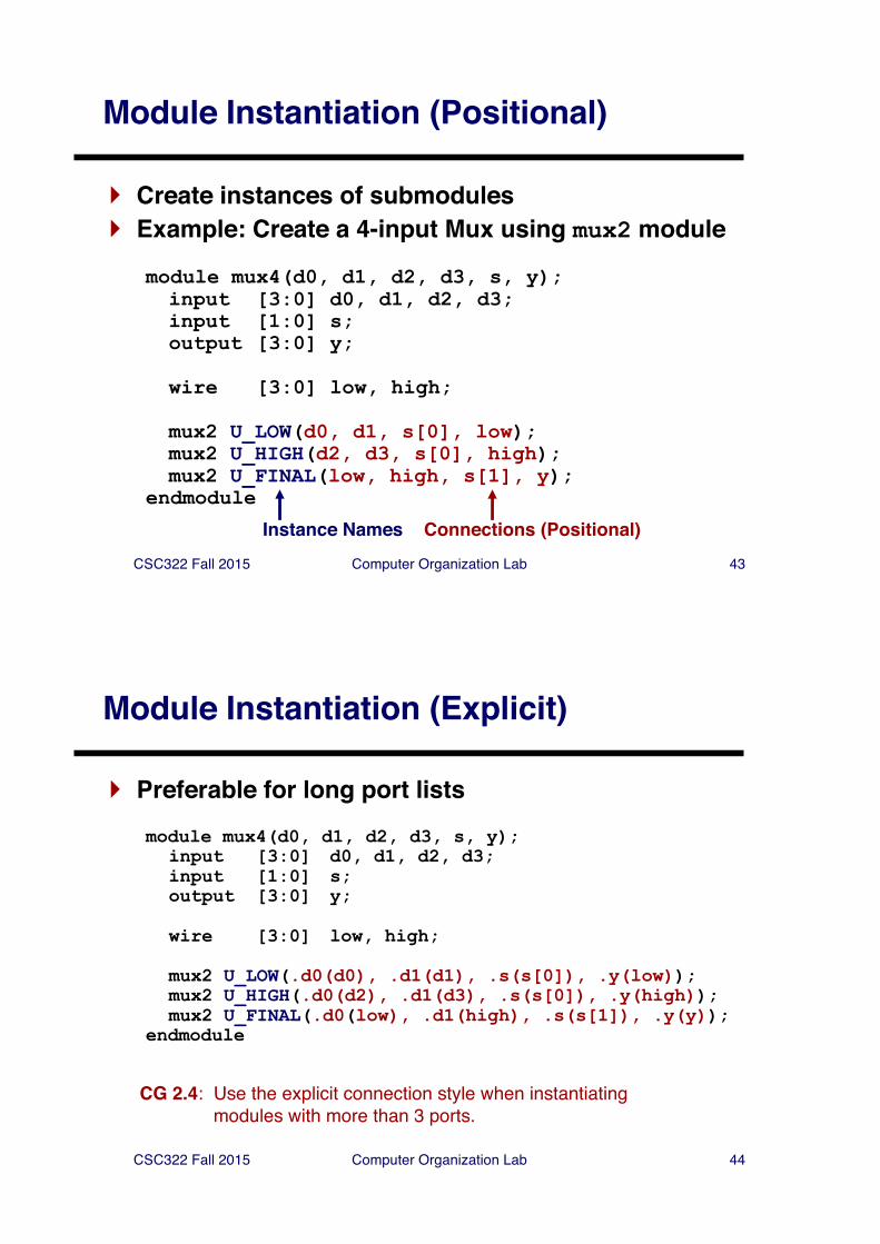
Module Instantiation (Positional)
} Create instances of submodules} Example: Create a 4-input Mux using mux2 module
module mux4(d0, d1, d2, d3, s, y);input [3:0] d0, d1, d2, d3;input [1:0] s;output [3:0] y;
wire [3:0] low, high;
mux2 U_LOW(d0, d1, s[0], low);mux2 U_HIGH(d2, d3, s[0], high);mux2 U_FINAL(low, high, s[1], y);
endmodule
Instance Names Connections (Positional)
CSC322 Fall 2015 Computer Organization Lab 44
Module Instantiation (Explicit)
} Preferable for long port listsmodule mux4(d0, d1, d2, d3, s, y);
input [3:0] d0, d1, d2, d3;input [1:0] s;output [3:0] y;
wire [3:0] low, high;
mux2 U_LOW(.d0(d0), .d1(d1), .s(s[0]), .y(low));mux2 U_HIGH(.d0(d2), .d1(d3), .s(s[0]), .y(high));mux2 U_FINAL(.d0(low), .d1(high), .s(s[1]), .y(y));
endmodule
CG 2.4: Use the explicit connection style when instantiating modules with more than 3 ports.
CSC322 Fall 2015 Computer Organization Lab 45
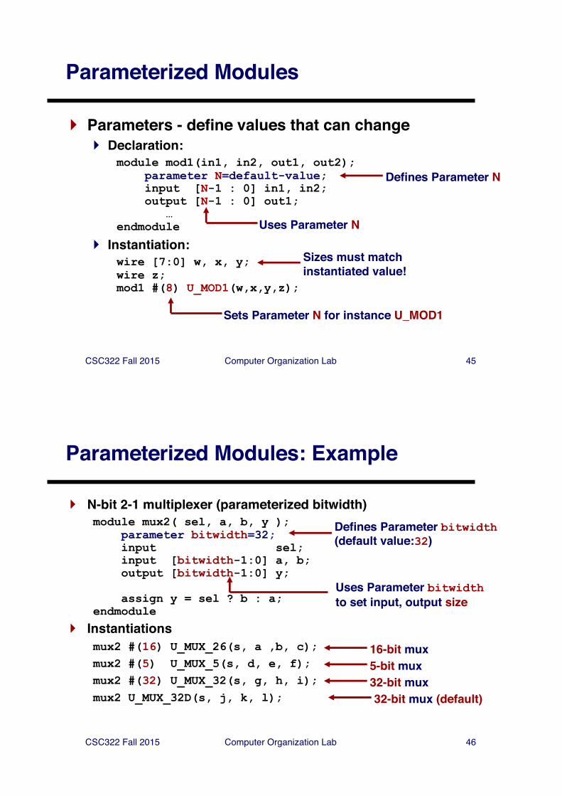
Parameterized Modules
} Parameters - define values that can change} Declaration:
module mod1(in1, in2, out1, out2);parameter N=default-value;input [N-1 : 0] in1, in2;output [N-1 : 0] out1;
…endmodule
} Instantiation:wire [7:0] w, x, y;wire z;mod1 #(8) U_MOD1(w,x,y,z);
Defines Parameter N
Uses Parameter N
Sets Parameter N for instance U_MOD1
Sizes must matchinstantiated value!
CSC322 Fall 2015 Computer Organization Lab 46
Parameterized Modules: Example
} N-bit 2-1 multiplexer (parameterized bitwidth)module mux2( sel, a, b, y );
parameter bitwidth=32;input sel;input [bitwidth-1:0] a, b;output [bitwidth-1:0] y;
assign y = sel ? b : a;endmodule
} Instantiationsmux2 #(16) U_MUX_26(s, a ,b, c);mux2 #(5) U_MUX_5(s, d, e, f);mux2 #(32) U_MUX_32(s, g, h, i);mux2 U_MUX_32D(s, j, k, l);
Defines Parameter bitwidth(default value:32)
Uses Parameter bitwidthto set input, output size
16-bit mux5-bit mux32-bit mux32-bit mux (default)
CSC322 Fall 2015 Computer Organization Lab 47
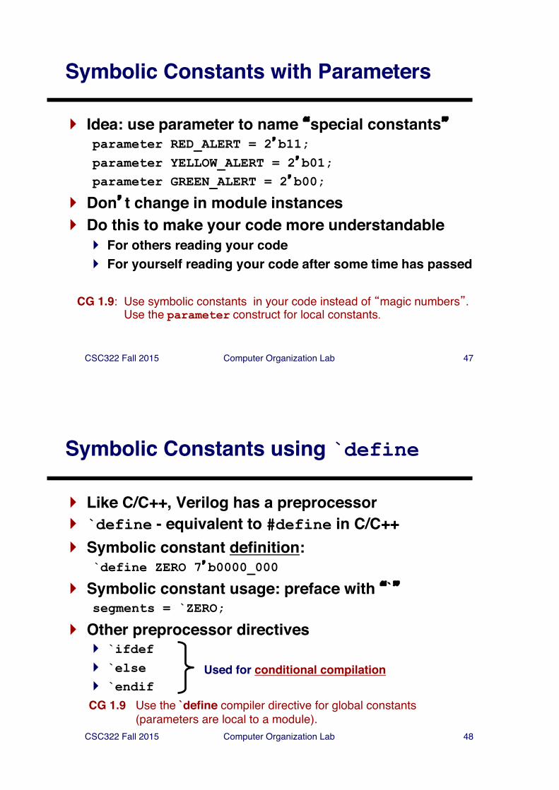
Symbolic Constants with Parameters
} Idea: use parameter to name �special constants�parameter RED_ALERT = 2�b11;parameter YELLOW_ALERT = 2�b01;parameter GREEN_ALERT = 2�b00;
} Don�t change in module instances} Do this to make your code more understandable
} For others reading your code} For yourself reading your code after some time has passed
CG 1.9: Use symbolic constants in your code instead of �magic numbers�. Use the parameter construct for local constants.
CSC322 Fall 2015 Computer Organization Lab 48
Symbolic Constants using `define
} Like C/C++, Verilog has a preprocessor} `define - equivalent to #define in C/C++} Symbolic constant definition:
`define ZERO 7�b0000_000
} Symbolic constant usage: preface with �`�segments = `ZERO;
} Other preprocessor directives} `ifdef} `else} `endif
Used for conditional compilation
CG 1.9 Use the `define compiler directive for global constants (parameters are local to a module).
CSC322 Fall 2015 Computer Organization Lab 49
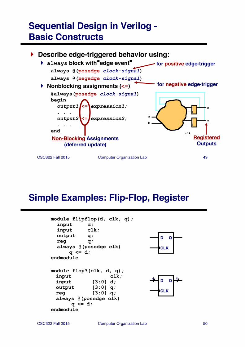
Sequential Design in Verilog -Basic Constructs} Describe edge-triggered behavior using:
} always block with�edge event�always @(posedge clock-signal)always @(negedge clock-signal)
} Nonblocking assignments (<=)@always(posedge clock-signal) beginoutput1 <= expression1;. . .output2 <= expression2; . . .
endRegistered
Outputs
for positive edge-trigger
for negative edge-trigger
Non-Blocking Assignments(deferred update)
a
b
x
y
clk
CSC322 Fall 2015 Computer Organization Lab 50
Simple Examples: Flip-Flop, Register
module flipflop(d, clk, q);input d;input clk;output q;reg q;always @(posedge clk)
q <= d;endmodule
module flop3(clk, d, q);input clk;input [3:0] d;output [3:0] q;reg [3:0] q;always @(posedge clk)
q <= d;endmodule
D
CLK
Q
D
CLK
Q4 4
CSC322 Fall 2015 Computer Organization Lab 51
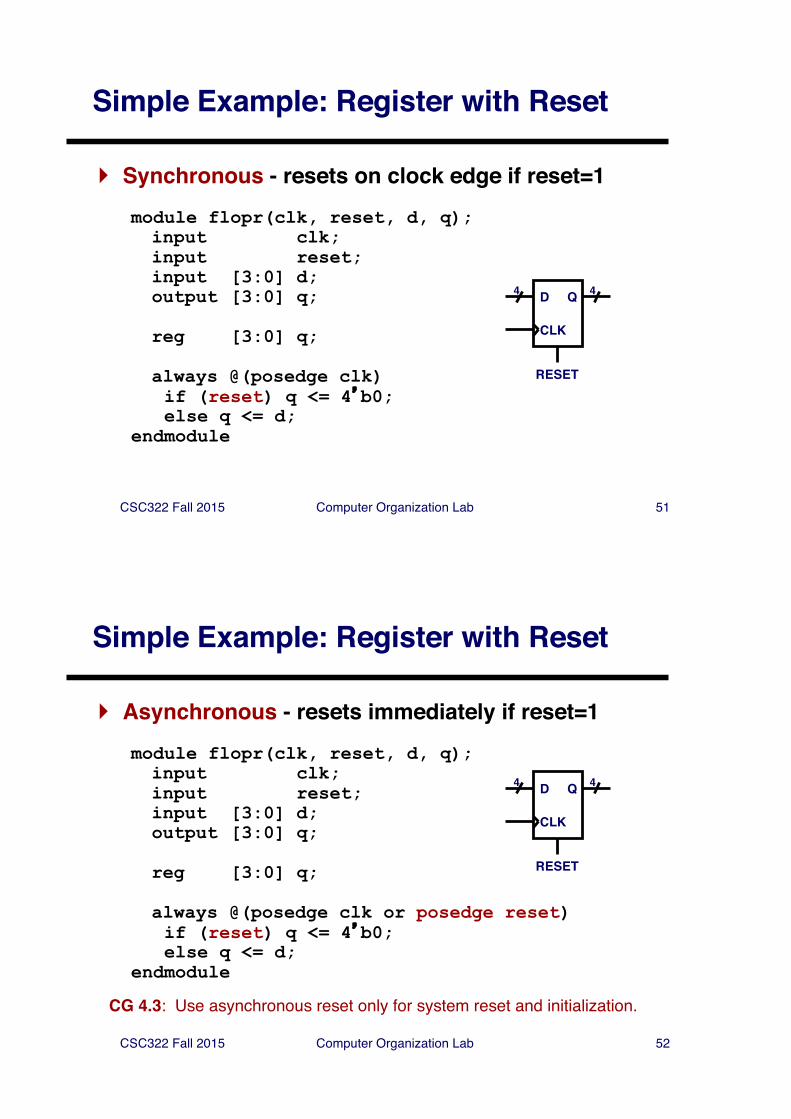
Simple Example: Register with Reset
} Synchronous - resets on clock edge if reset=1module flopr(clk, reset, d, q);input clk;input reset;input [3:0] d;output [3:0] q;
reg [3:0] q;
always @(posedge clk)if (reset) q <= 4�b0;else q <= d;
endmodule
D
CLK
Q4 4
RESET
CSC322 Fall 2015 Computer Organization Lab 52
Simple Example: Register with Reset
} Asynchronous - resets immediately if reset=1module flopr(clk, reset, d, q);input clk;input reset;input [3:0] d;output [3:0] q;
reg [3:0] q;
always @(posedge clk or posedge reset)if (reset) q <= 4�b0;else q <= d;
endmodule
D
CLK
Q4 4
RESET
CG 4.3: Use asynchronous reset only for system reset and initialization.
CSC322 Fall 2015 Computer Organization Lab 53
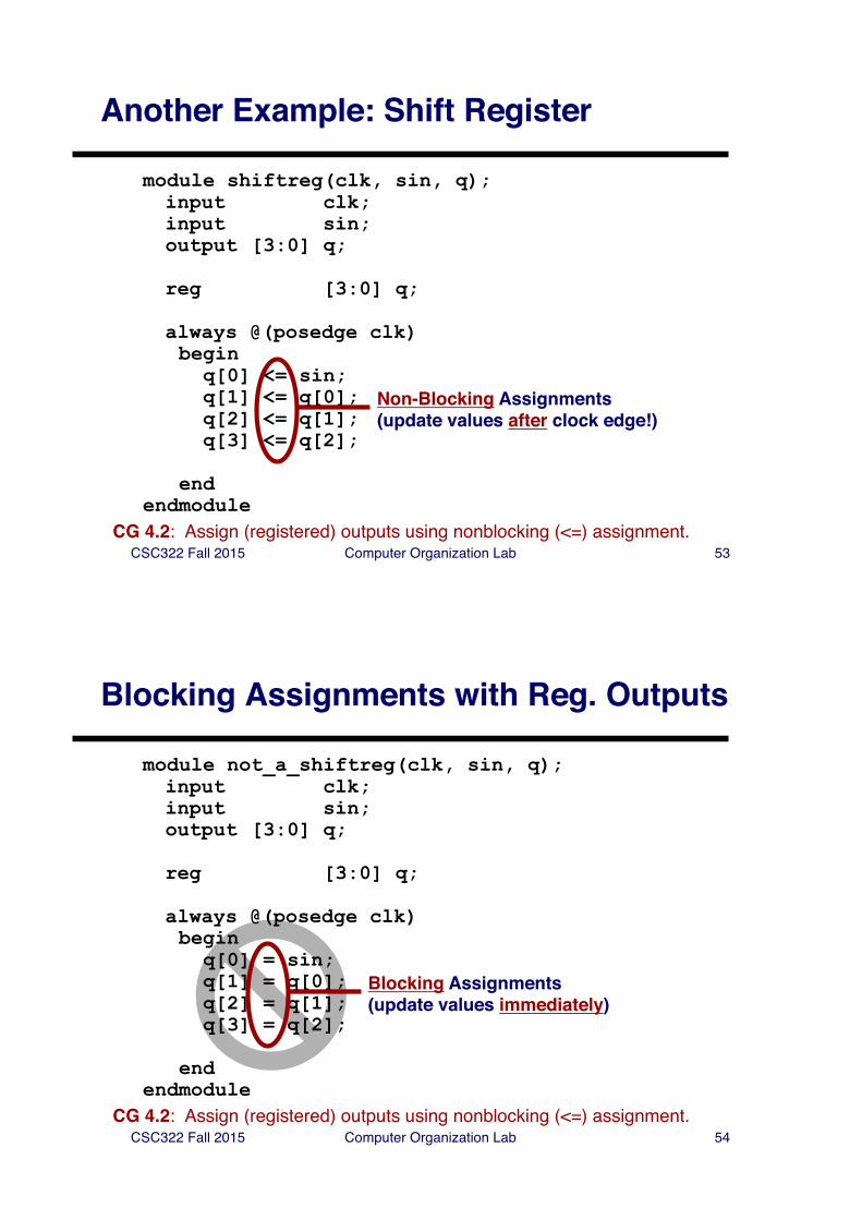
Another Example: Shift Register
module shiftreg(clk, sin, q);input clk;input sin;output [3:0] q;
reg [3:0] q;
always @(posedge clk)begin
q[0] <= sin; q[1] <= q[0];q[2] <= q[1];q[3] <= q[2];
endendmodule
Non-Blocking Assignments(update values after clock edge!)
CG 4.2: Assign (registered) outputs using nonblocking (<=) assignment.
CSC322 Fall 2015 Computer Organization Lab 54
Blocking Assignments with Reg. Outputs
module not_a_shiftreg(clk, sin, q);input clk;input sin;output [3:0] q;
reg [3:0] q;
always @(posedge clk)begin
q[0] = sin; q[1] = q[0];q[2] = q[1];q[3] = q[2];
endendmodule
Blocking Assignments(update values immediately)
CG 4.2: Assign (registered) outputs using nonblocking (<=) assignment.
CSC322 Fall 2015 Computer Organization Lab 55
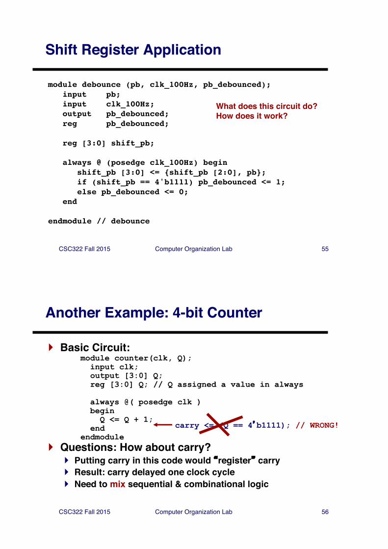
Shift Register Application
module debounce (pb, clk_100Hz, pb_debounced);input pb;input clk_100Hz;output pb_debounced;reg pb_debounced;
reg [3:0] shift_pb;
always @ (posedge clk_100Hz) beginshift_pb [3:0] <= {shift_pb [2:0], pb};if (shift_pb == 4'b1111) pb_debounced <= 1;else pb_debounced <= 0;
end
endmodule // debounce
What does this circuit do?How does it work?
CSC322 Fall 2015 Computer Organization Lab 56
Another Example: 4-bit Counter
} Basic Circuit:module counter(clk, Q);input clk;output [3:0] Q;reg [3:0] Q; // Q assigned a value in always
always @( posedge clk )beginQ <= Q + 1;
endendmodule
} Questions: How about carry?} Putting carry in this code would �register� carry} Result: carry delayed one clock cycle} Need to mix sequential & combinational logic
carry <= (Q == 4�b1111); // WRONG!
CSC322 Fall 2015 Computer Organization Lab 57
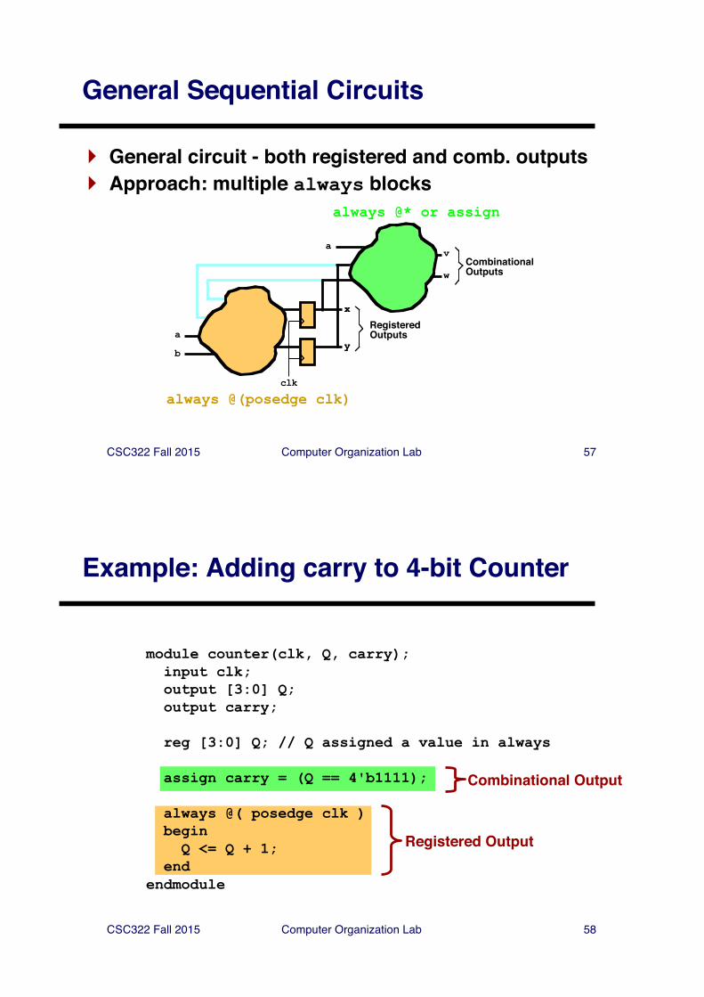
General Sequential Circuits
} General circuit - both registered and comb. outputs} Approach: multiple always blocks
av
wCombinationalOutputs
x
y
RegisteredOutputsa
b
x
y
clk
always @(posedge clk)
always @* or assign
CSC322 Fall 2015 Computer Organization Lab 58
Registered Output
Combinational Output
Example: Adding carry to 4-bit Counter
module counter(clk, Q, carry);input clk;output [3:0] Q;output carry;
reg [3:0] Q; // Q assigned a value in always
assign carry = (Q == 4'b1111);
always @( posedge clk )beginQ <= Q + 1;
endendmodule
CSC322 Fall 2015 Computer Organization Lab 59
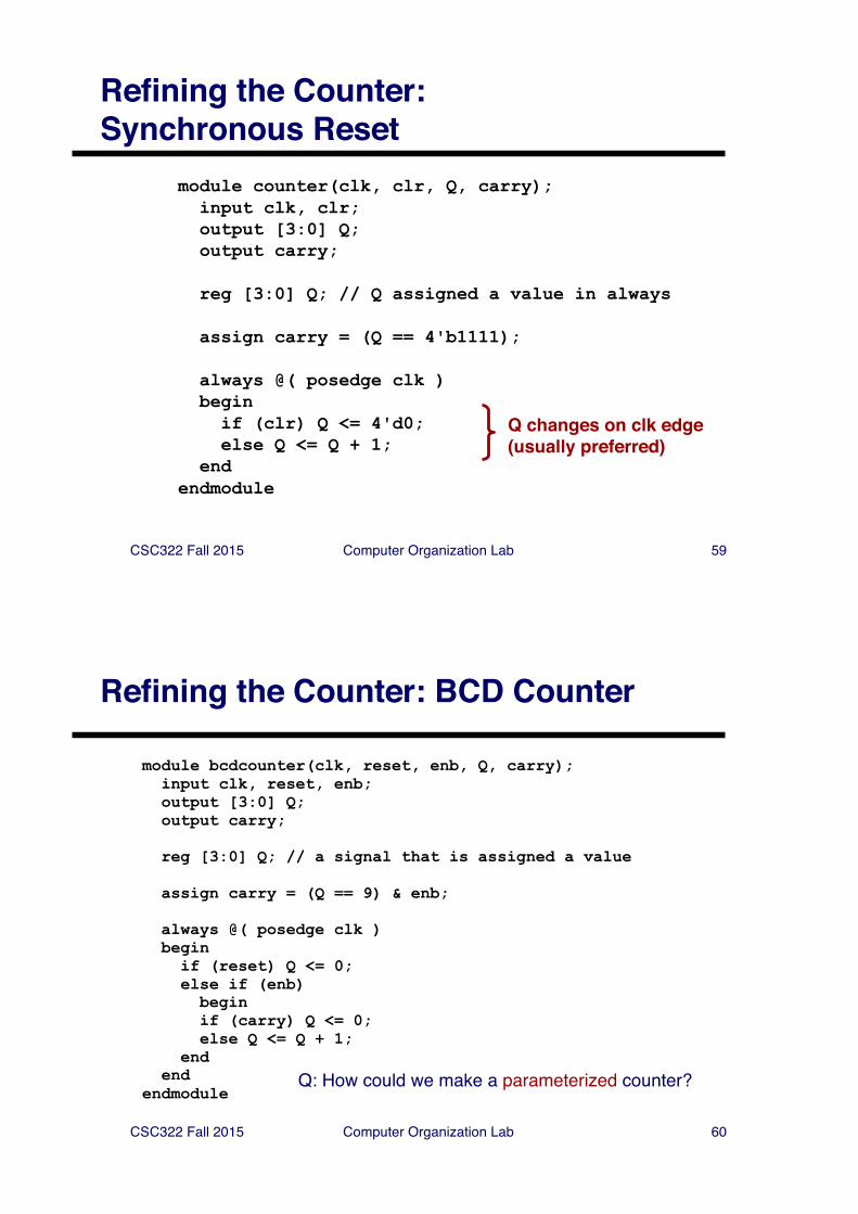
Refining the Counter: Synchronous Reset
module counter(clk, clr, Q, carry);input clk, clr;output [3:0] Q;output carry;
reg [3:0] Q; // Q assigned a value in always
assign carry = (Q == 4'b1111);
always @( posedge clk )beginif (clr) Q <= 4'd0;else Q <= Q + 1;
endendmodule
Q changes on clk edge (usually preferred)
CSC322 Fall 2015 Computer Organization Lab 60
Refining the Counter: BCD Counter
module bcdcounter(clk, reset, enb, Q, carry);input clk, reset, enb;output [3:0] Q;output carry;
reg [3:0] Q; // a signal that is assigned a value
assign carry = (Q == 9) & enb;
always @( posedge clk )beginif (reset) Q <= 0;else if (enb) beginif (carry) Q <= 0;else Q <= Q + 1;
endend
endmoduleQ: How could we make a parameterized counter?
CSC322 Fall 2015 Computer Organization Lab 61
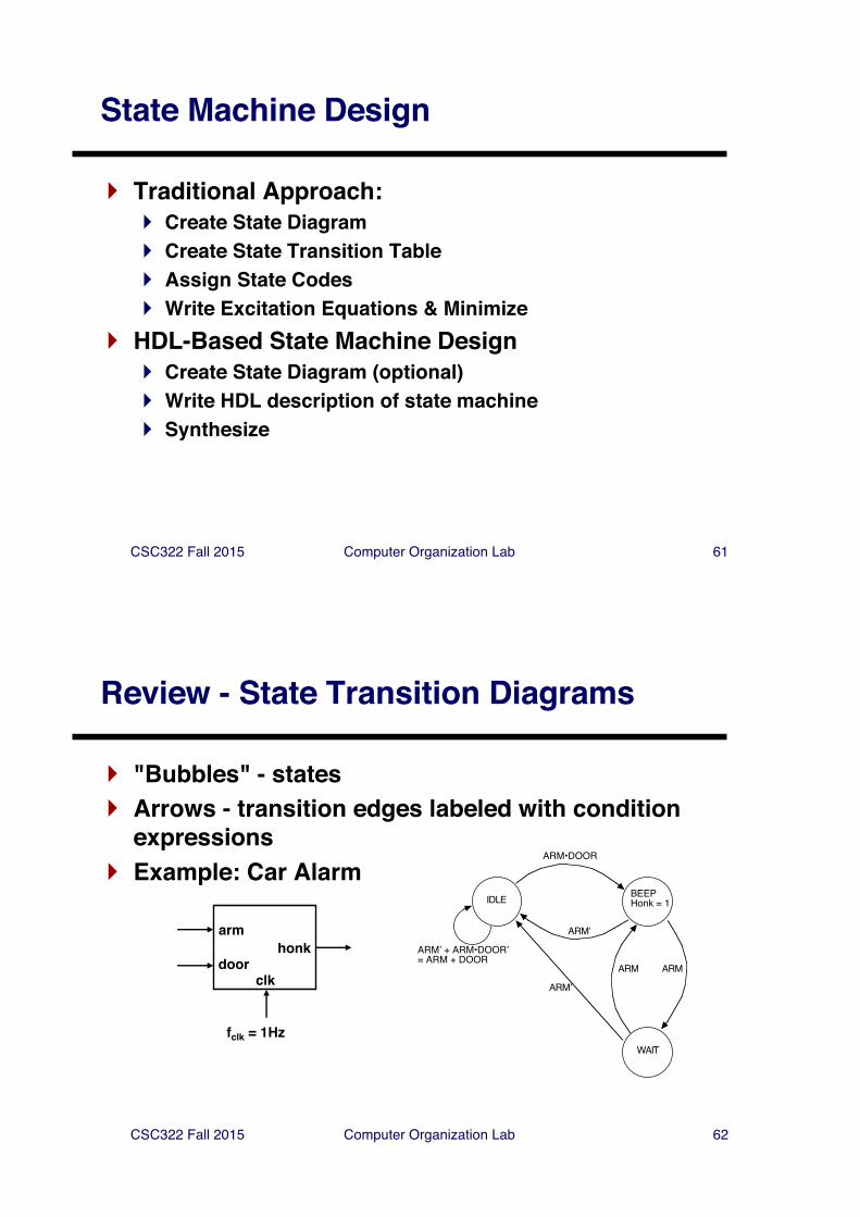
State Machine Design
} Traditional Approach:} Create State Diagram} Create State Transition Table} Assign State Codes} Write Excitation Equations & Minimize
} HDL-Based State Machine Design} Create State Diagram (optional)} Write HDL description of state machine} Synthesize
CSC322 Fall 2015 Computer Organization Lab 62
Review - State Transition Diagrams
} "Bubbles" - states} Arrows - transition edges labeled with condition
expressions} Example: Car Alarm
arm
doorhonk
clk
fclk = 1Hz
IDLE BEEPHonk = 1
WAIT
ARM•DOOR
ARMʼ + ARM•DOORʼ= ARM + DOOR
ARMʼ
ARMARM
ARMʼ
CSC322 Fall 2015 Computer Organization Lab 63
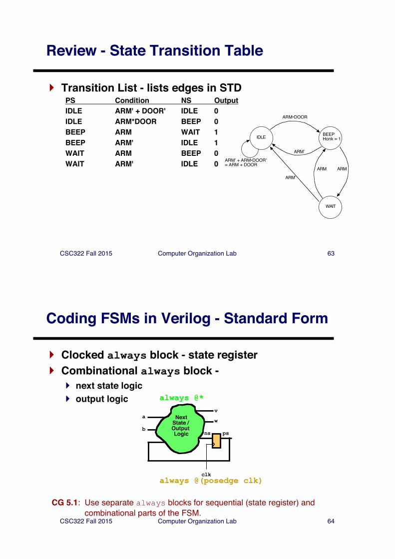
Review - State Transition Table
} Transition List - lists edges in STDPS Condition NS OutputIDLE ARM' + DOOR' IDLE 0IDLE ARM*DOOR BEEP 0BEEP ARM WAIT 1BEEP ARM' IDLE 1WAIT ARM BEEP 0WAIT ARM' IDLE 0
IDLE BEEPHonk = 1
WAIT
ARM•DOOR
ARMʼ + ARM•DOORʼ= ARM + DOOR
ARMʼ
ARMARM
ARMʼ
CSC322 Fall 2015 Computer Organization Lab 64
Coding FSMs in Verilog - Standard Form
} Clocked always block - state register} Combinational always block -
} next state logic} output logic
avwNext
State / Output Logic psns
b
clkalways @(posedge clk)
always @*
CG 5.1: Use separate always blocks for sequential (state register) and combinational parts of the FSM.
CSC322 Fall 2015 Computer Organization Lab 65
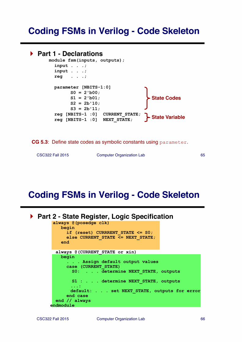
Coding FSMs in Verilog - Code Skeleton
} Part 1 - Declarationsmodule fsm(inputs, outputs);input . . .;input . . .;reg . . .;
parameter [NBITS-1:0]S0 = 2'b00;S1 = 2'b01;S2 = 2b'10;S3 = 2b'11;
reg [NBITS-1 :0] CURRENT_STATE;reg [NBITS-1 :0] NEXT_STATE;
State Codes
State Variable
CG 5.3: Define state codes as symbolic constants using parameter.
CSC322 Fall 2015 Computer Organization Lab 66
Coding FSMs in Verilog - Code Skeleton
} Part 2 - State Register, Logic Specificationalways @(posedge clk)
beginif (reset) CURRRENT_STATE <= S0;else CURRENT_STATE <= NEXT_STATE;
end
always @(CURRENT_STATE or xin)begin. . . Assign default output valuescase (CURRENT_STATE)S0: . . . determine NEXT_STATE, outputs
S1 : . . . determine NEXT_STATE, outputs...:default: . . . set NEXT_STATE, outputs for error
end caseend // always
endmodule
CSC322 Fall 2015 Computer Organization Lab 67
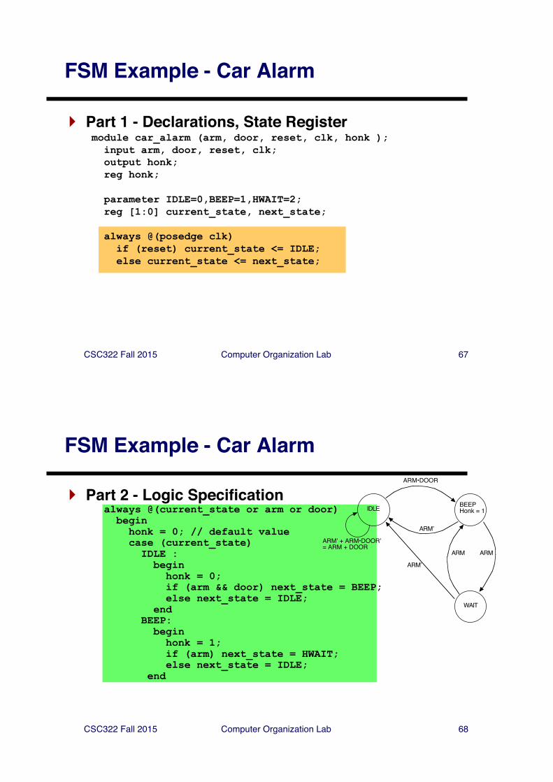
FSM Example - Car Alarm
} Part 1 - Declarations, State Registermodule car_alarm (arm, door, reset, clk, honk );input arm, door, reset, clk;output honk;reg honk;
parameter IDLE=0,BEEP=1,HWAIT=2;reg [1:0] current_state, next_state;
always @(posedge clk)if (reset) current_state <= IDLE;else current_state <= next_state;
CSC322 Fall 2015 Computer Organization Lab 68
FSM Example - Car Alarm
} Part 2 - Logic Specificationalways @(current_state or arm or door) beginhonk = 0; // default valuecase (current_state)IDLE : beginhonk = 0;if (arm && door) next_state = BEEP;else next_state = IDLE;
endBEEP:beginhonk = 1;if (arm) next_state = HWAIT;else next_state = IDLE;
end
IDLE BEEPHonk = 1
WAIT
ARM•DOOR
ARMʼ + ARM•DOORʼ= ARM + DOOR
ARMʼ
ARMARM
ARMʼ
CSC322 Fall 2015 Computer Organization Lab 69
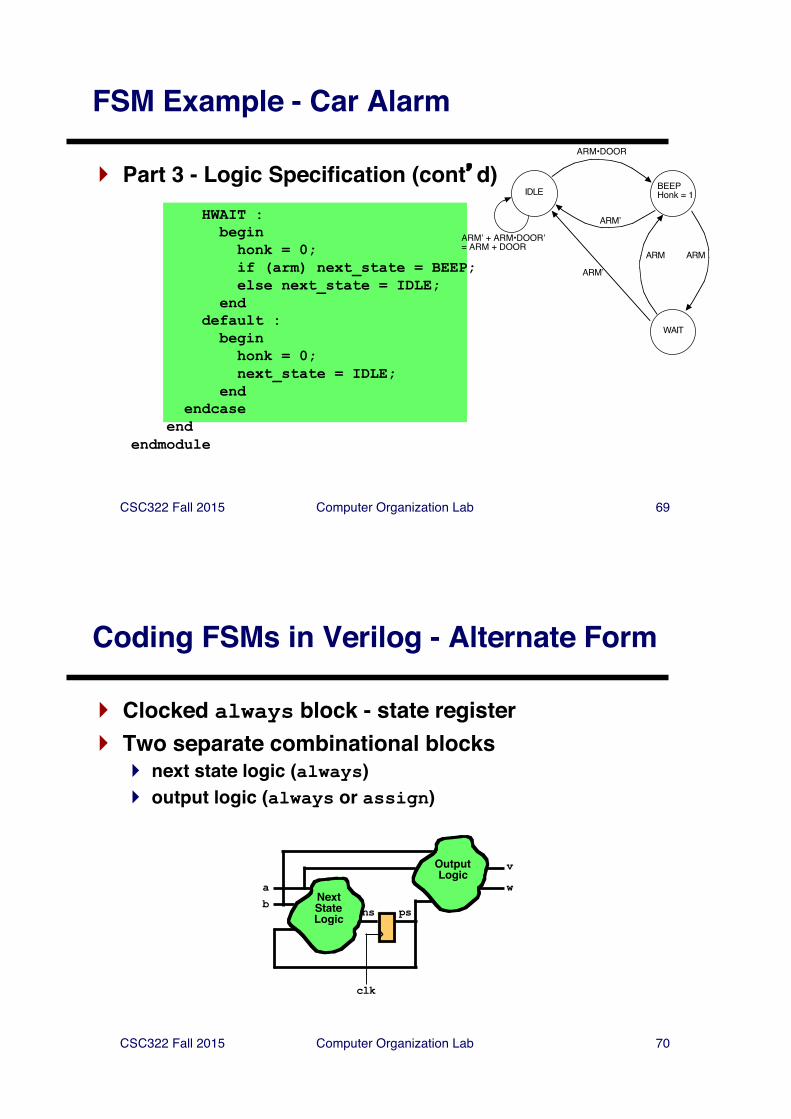
FSM Example - Car Alarm
} Part 3 - Logic Specification (cont�d)HWAIT :beginhonk = 0;if (arm) next_state = BEEP;else next_state = IDLE;
enddefault :beginhonk = 0;next_state = IDLE;
endendcase
endendmodule
IDLE BEEPHonk = 1
WAIT
ARM•DOOR
ARMʼ + ARM•DOORʼ= ARM + DOOR
ARMʼ
ARMARM
ARMʼ
CSC322 Fall 2015 Computer Organization Lab 70
Coding FSMs in Verilog - Alternate Form
} Clocked always block - state register} Two separate combinational blocks
} next state logic (always) } output logic (always or assign)
v
wa
clk
NextStateLogic psns
b
OutputLogic
CSC322 Fall 2015 Computer Organization Lab 71
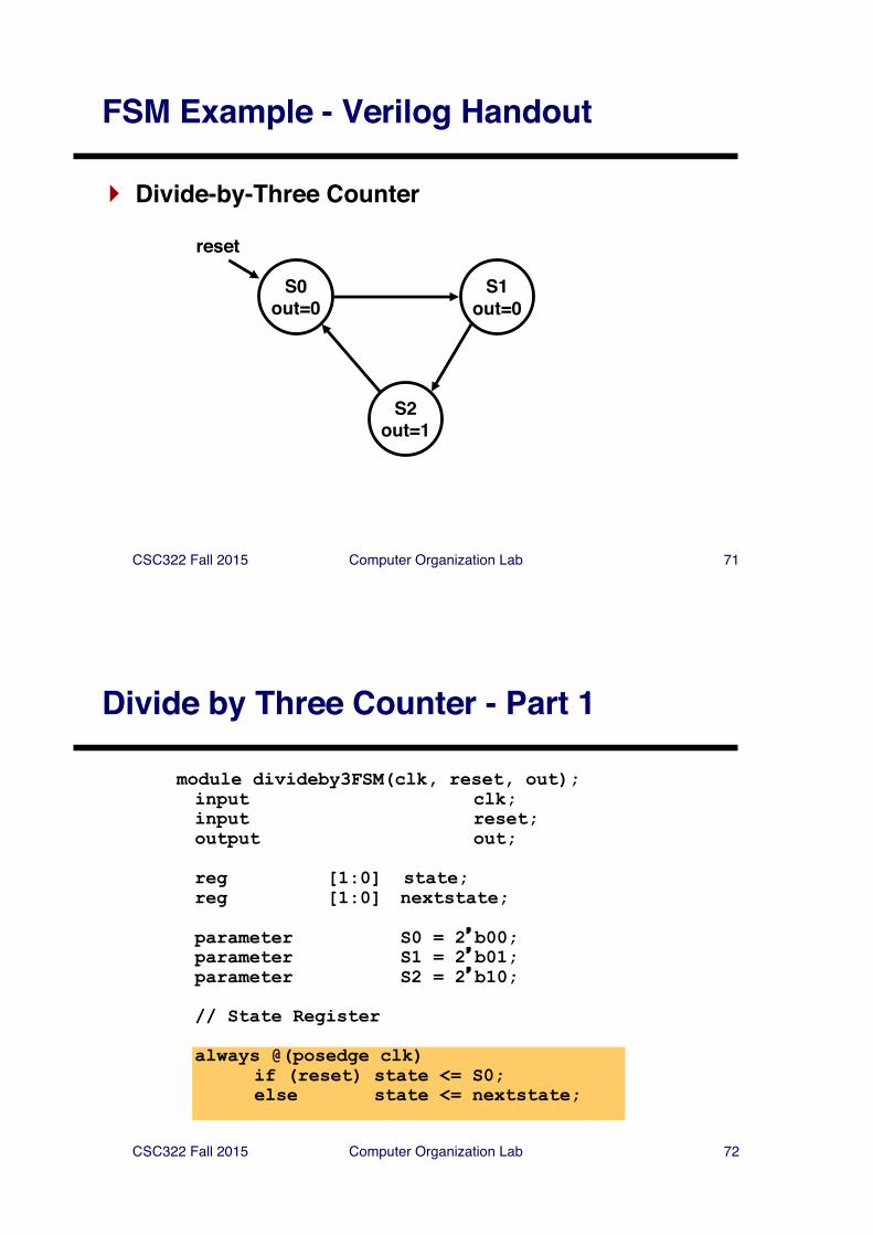
FSM Example - Verilog Handout
} Divide-by-Three Counter
S0out=0
S1out=0
S2out=1
reset
CSC322 Fall 2015 Computer Organization Lab 72
Divide by Three Counter - Part 1
module divideby3FSM(clk, reset, out);input clk;input reset;output out;
reg [1:0] state;reg [1:0] nextstate;
parameter S0 = 2�b00;parameter S1 = 2�b01;parameter S2 = 2�b10;
// State Register
always @(posedge clk)if (reset) state <= S0;else state <= nextstate;
CSC322 Fall 2015 Computer Organization Lab 73
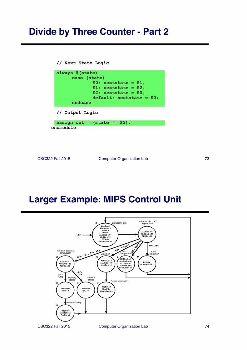
Divide by Three Counter - Part 2
// Next State Logic
always @(state)case (state)
S0: nextstate = S1;S1: nextstate = S2;S2: nextstate = S0;default: nextstate = S0;
endcase
// Output Logic
assign out = (state == S2);endmodule
CSC322 Fall 2015 Computer Organization Lab 74
Larger Example: MIPS Control Unit
0 Instruction FetchInstruction decode /
register fetch
1
2
Memory addresscomputation
3
4
5 7
6 8 9Execution
BranchCompletion
JumpCompletion
Memoryaccess
Memoryaccess R-type completion
Writeback step
Start
MemReadALUSrcA = 0
IorD = 0IRWrite
ALUSrcB = 01ALUOp = 00
PCWritePCSource = 00
(OP = ʻJMPʼ)
ALUSrcA = 0ALUSrcB = 11ALUOp = 00
ALUSrcA = 1ALUSrcB = 10ALUOp = 00
(OP = ʻLWʼ)
(OP = (ʻSWʼ)
MemReadIorD = 1
RegWriteMemToReg=1
RegDst = 0
MemWriteIorD = 1
ALUSrcA = 1ALUSrcB = 00ALUOp = 10
RegDst = 1RegWrite
MemtoReg = 0
ALUSrcA = 1ALUSrcB = 00ALUOp = 01
PCWriteCondPCSource = 01
PCWritePCSource = 10
CSC322 Fall 2015 Computer Organization Lab 75
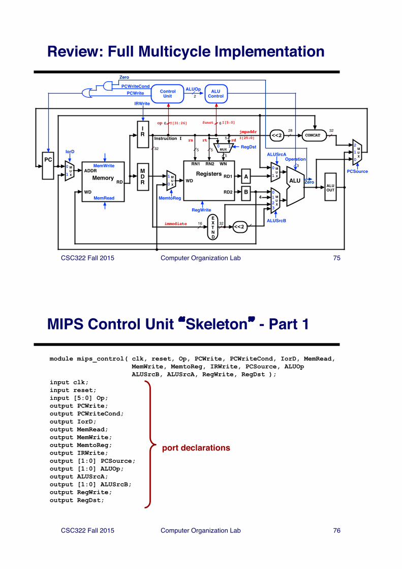
Review: Full Multicycle Implementation
ALUControl
ControlUnit
6 6op I[31:26] funct I[5:0]
ALUOp2
5 5
RD1
RD2
RN1 RN2 WN
WD
RegWrite
Registers
Operation
ALU
3
EXTND
16 32
ZeroRD
WDMemRead
MemoryADDR
MemWrite
5
Instruction I
32
ALUSrcB<<2
PC
4
RegDst
5
IR
MDR
MUX
0123
MUX
1
0
MUX
0
1A
BALUOUT
0
1
2MUX
<<2 CONCAT28 32
MUX
0
1
ALUSrcA
jmpaddrI[25:0]rd
MUX0 1
rtrs
immediate
PCSource
MemtoReg
IorD
PCWriteCondPCWrite
Zero
IRWrite
CSC322 Fall 2015 Computer Organization Lab 76
MIPS Control Unit �Skeleton� - Part 1
module mips_control( clk, reset, Op, PCWrite, PCWriteCond, IorD, MemRead, MemWrite, MemtoReg, IRWrite, PCSource, ALUOpALUSrcB, ALUSrcA, RegWrite, RegDst );
input clk;input reset;input [5:0] Op;output PCWrite;output PCWriteCond;output IorD;output MemRead;output MemWrite;output MemtoReg;output IRWrite;output [1:0] PCSource;output [1:0] ALUOp;output ALUSrcA;output [1:0] ALUSrcB;output RegWrite;output RegDst;
port declarations
CSC322 Fall 2015 Computer Organization Lab 77
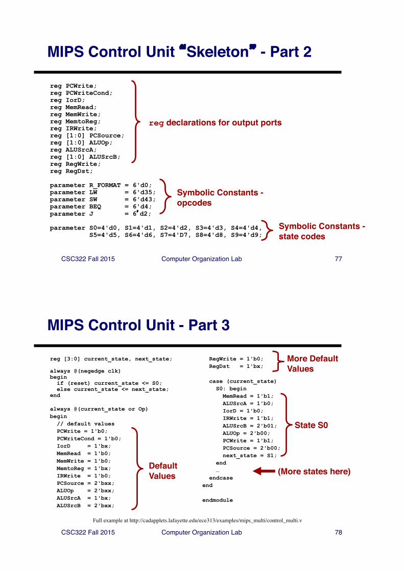
MIPS Control Unit �Skeleton� - Part 2
reg PCWrite;reg PCWriteCond;reg IorD;reg MemRead;reg MemWrite;reg MemtoReg;reg IRWrite;reg [1:0] PCSource;reg [1:0] ALUOp;reg ALUSrcA;reg [1:0] ALUSrcB;reg RegWrite;reg RegDst;
parameter R_FORMAT = 6'd0;parameter LW = 6'd35;parameter SW = 6'd43;parameter BEQ = 6'd4;parameter J = 6�d2;
parameter S0=4'd0, S1=4'd1, S2=4'd2, S3=4'd3, S4=4'd4,S5=4'd5, S6=4'd6, S7=4'D7, S8=4'd8, S9=4'd9;
Symbolic Constants -opcodes
Symbolic Constants -state codes
reg declarations for output ports
CSC322 Fall 2015 Computer Organization Lab 78
MIPS Control Unit - Part 3
reg [3:0] current_state, next_state;
always @(negedge clk) begin
if (reset) current_state <= S0;else current_state <= next_state;
end
always @(current_state or Op)begin
// default valuesPCWrite = 1'b0;PCWriteCond = 1'b0;IorD = 1'bx;MemRead = 1'b0;MemWrite = 1'b0;MemtoReg = 1'bx;IRWrite = 1'b0;PCSource = 2'bxx;ALUOp = 2'bxx;ALUSrcA = 1'bx;ALUSrcB = 2'bxx;
RegWrite = 1'b0;RegDst = 1'bx;
case (current_state)S0: begin
MemRead = 1'b1;ALUSrcA = 1'b0;IorD = 1'b0;IRWrite = 1'b1;ALUSrcB = 2'b01;ALUOp = 2'b00;PCWrite = 1'b1;PCSource = 2'b00;next_state = S1;
end…
endcaseend
endmodule
(More states here)DefaultValues
More DefaultValues
State S0
Full example at http://cadapplets.lafayette.edu/ece313/examples/mips_multi/control_multi.v
CSC322 Fall 2015 Computer Organization Lab 79
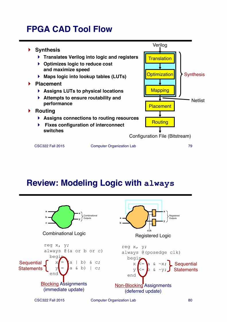
FPGA CAD Tool Flow
Translation
Optimization
Mapping
Placement
Routing
Verilog
Configuration File (Bitstream)
Synthesis
} Synthesis} Translates Verilog into logic and registers} Optimizes logic to reduce cost
and maximize speed} Maps logic into lookup tables (LUTs)
} Placement} Assigns LUTs to physical locations} Attempts to ensure routability and
performance} Routing
} Assigns connections to routing resources} Fixes configuration of interconnect
switches
Netlist
CSC322 Fall 2015 Computer Organization Lab 80
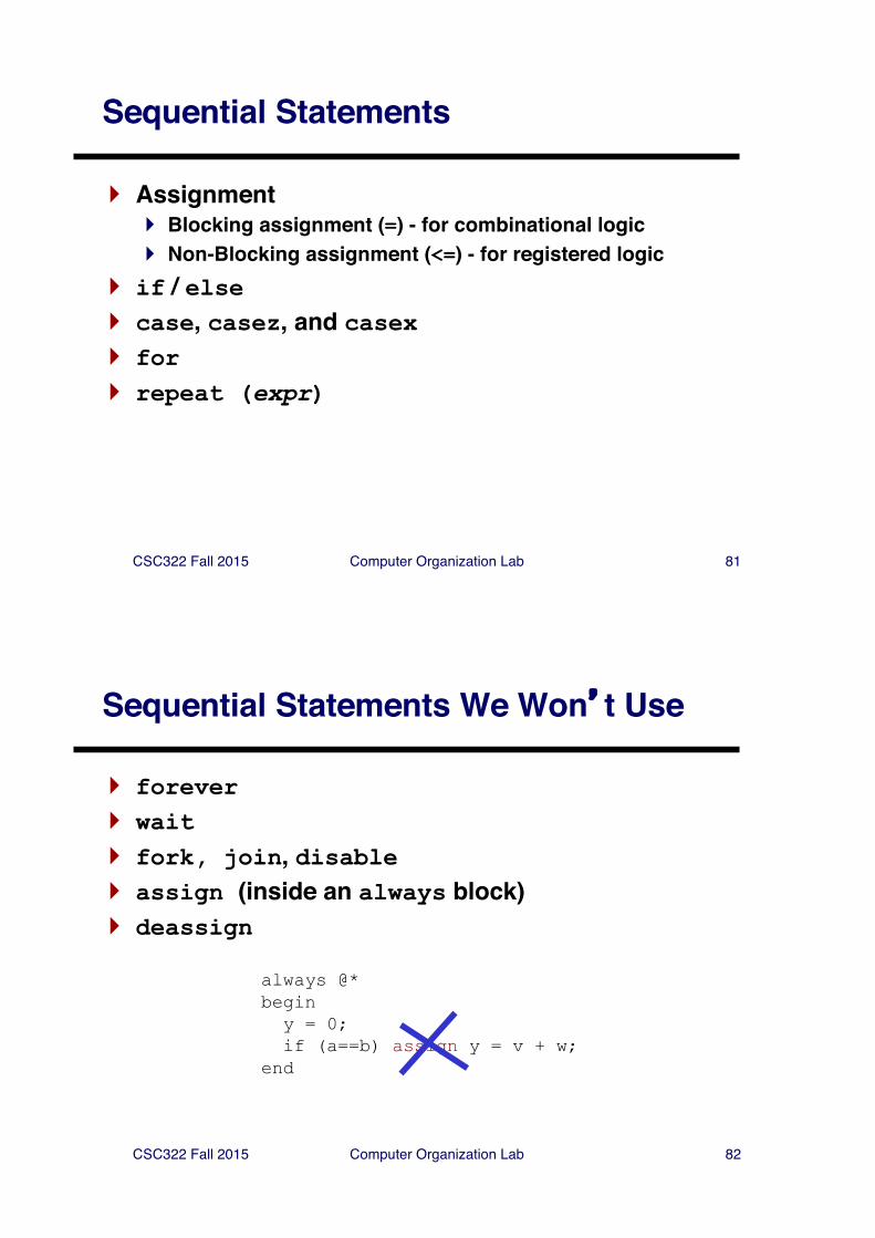
Review: Modeling Logic with always
a
b
c
x
yCombinationalOutputs a
b
x
y
clk
RegisteredOutputs
Combinational Logic Registered Logic
reg x, y;always @(a or b or c)beginx = (a | b) & c;y = (a & b) | c;
end
reg x, y;always @(posedge clk)beginx <= a & ~x;y <= b & ~y;
end
Non-Blocking Assignments(deferred update)
Blocking Assignments(immediate update)
SequentialStatements
SequentialStatements
CSC322 Fall 2015 Computer Organization Lab 81
Sequential Statements
} Assignment} Blocking assignment (=) - for combinational logic} Non-Blocking assignment (<=) - for registered logic
} if / else} case, casez, and casex} for} repeat (expr)
CSC322 Fall 2015 Computer Organization Lab 82
Sequential Statements We Won�t Use
} forever} wait} fork, join, disable} assign (inside an always block)} deassign
always @*beginy = 0;if (a==b) assign y = v + w;
end
CSC322 Fall 2015 Computer Organization Lab 83
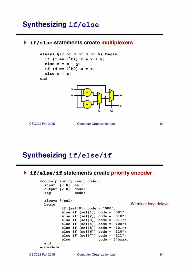
Synthesizing if/else
} if/else statements create multiplexers
always @(c or d or x or y) beginif (c == 1�b1) z = x + y;else z = x - y;if (d == 1�b0) w = z;else w = x;
end
+
-c
1
0
xy z
d
1
0w
z
CSC322 Fall 2015 Computer Organization Lab 84
Synthesizing if/else/if
} if/else/if statements create priority encodermodule priority (sel, code);input [7:0] sel;output [2:0] code;reg code;
always @(sel)begin
if (sel[0]) code = "000";else if (sel[1]) code = "001"; else if (sel[2]) code = "010"; else if (sel[3]) code = "011"; else if (sel[4]) code = "100"; else if (sel[5]) code = "101"; else if (sel[6]) code = "110"; else if (sel[7]) code = "111"; else code = 3'bxxx;
end endmodule
Warning: long delays!
CSC322 Fall 2015 Computer Organization Lab 85
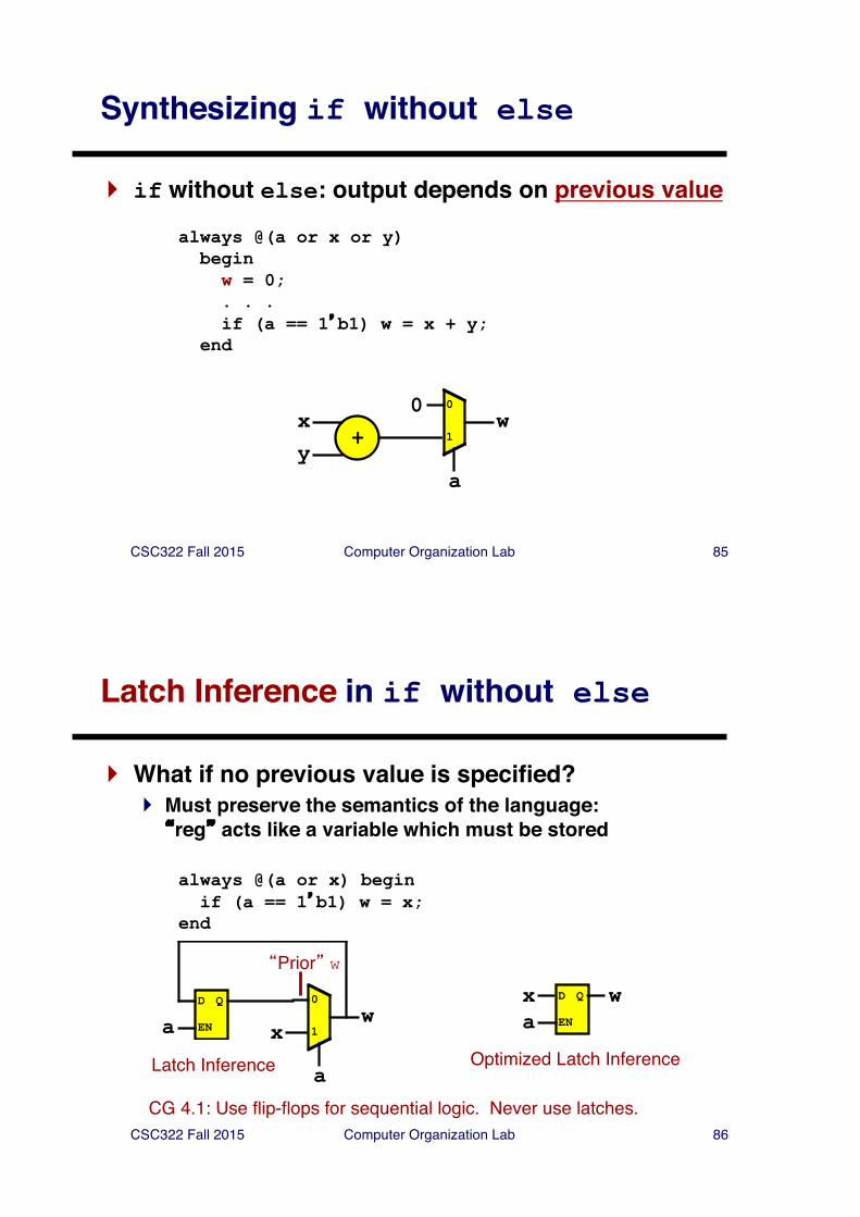
Synthesizing if without else
} if without else: output depends on previous value
always @(a or x or y) beginw = 0;. . .if (a == 1�b1) w = x + y;
end
+xy
a
0
1w
0
CSC322 Fall 2015 Computer Organization Lab 86
Latch Inference in if without else
} What if no previous value is specified?} Must preserve the semantics of the language:�reg� acts like a variable which must be stored
always @(a or x) beginif (a == 1�b1) w = x;
end
x
a
0
1w
�Prior� w
D Q
a EN
Latch Inference Optimized Latch Inference
x D Q
a EN
w
CG 4.1: Use flip-flops for sequential logic. Never use latches.
CSC322 Fall 2015 Computer Organization Lab 87
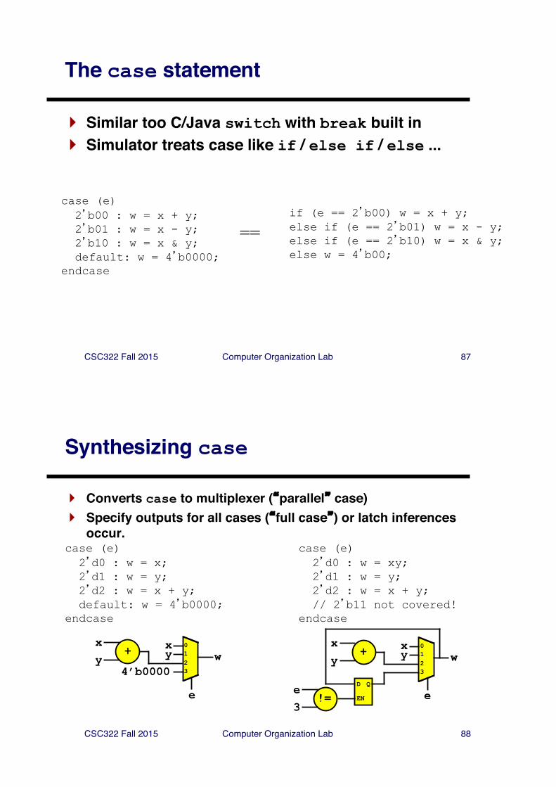
The case statement
} Similar too C/Java switch with break built in} Simulator treats case like if / else if / else ...
case (e)2�b00 : w = x + y;2�b01 : w = x - y;2�b10 : w = x & y;default: w = 4�b0000;
endcase
if (e == 2�b00) w = x + y;else if (e == 2�b01) w = x - y;else if (e == 2�b10) w = x & y;else w = 4�b00;
==
CSC322 Fall 2015 Computer Organization Lab 88
Synthesizing case
} Converts case to multiplexer (�parallel� case)} Specify outputs for all cases (�full case�) or latch inferences
occur.case (e)2�d0 : w = x;2�d1 : w = y;2�d2 : w = x + y;default: w = 4�b0000;
endcase
case (e)2�d0 : w = xy;2�d1 : w = y;2�d2 : w = x + y;// 2�b11 not covered!
endcase
x
e
0
w123
y4’b0000
+xy
x
e
0
w123
y+xy
D Q
EN!=e3
CSC322 Fall 2015 Computer Organization Lab 89
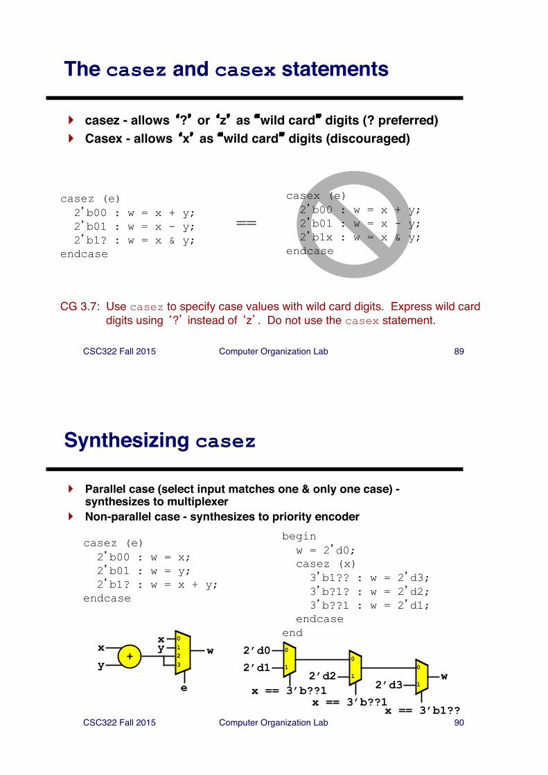
The casez and casex statements
} casez - allows �?� or �z� as �wild card� digits (? preferred)} Casex - allows �x� as �wild card� digits (discouraged)
casez (e)2�b00 : w = x + y;2�b01 : w = x - y;2�b1? : w = x & y;
endcase
==
casex (e)2�b00 : w = x + y;2�b01 : w = x - y;2�b1x : w = x & y;
endcase
CG 3.7: Use casez to specify case values with wild card digits. Express wild card digits using �?� instead of �z�. Do not use the casex statement.
CSC322 Fall 2015 Computer Organization Lab 90
Synthesizing casez
} Parallel case (select input matches one & only one case) -synthesizes to multiplexer
} Non-parallel case - synthesizes to priority encoder
casez (e)2�b00 : w = x;2�b01 : w = y;2�b1? : w = x + y;
endcase
beginw = 2�d0;casez (x)3�b1?? : w = 2�d3;3�b?1? : w = 2�d2;3�b??1 : w = 2�d1;
endcaseendx
e
0
w123
y+
xy
2’d2
x == 3’b??1
0
1
2’d3
0
1
x == 3’b1??
2’d1
0
1
x == 3’b??1
2’d0
w
CSC322 Fall 2015 Computer Organization Lab 91
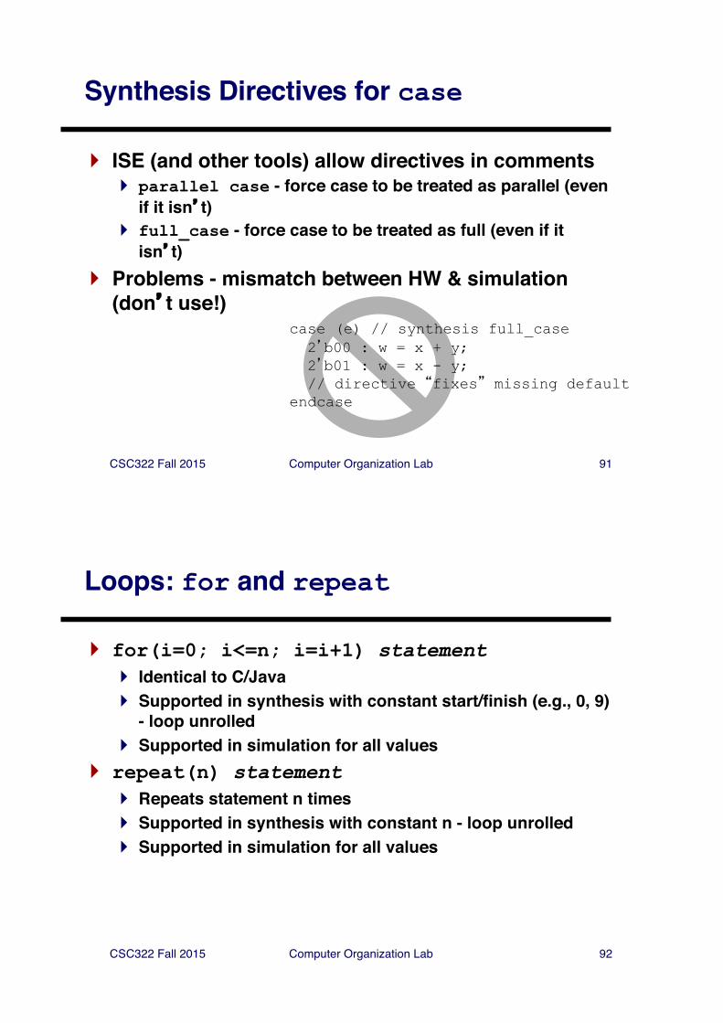
Synthesis Directives for case
} ISE (and other tools) allow directives in comments} parallel case - force case to be treated as parallel (even
if it isn�t)} full_case - force case to be treated as full (even if it
isn�t)} Problems - mismatch between HW & simulation
(don�t use!)case (e) // synthesis full_case2�b00 : w = x + y;2�b01 : w = x - y;// directive �fixes� missing default
endcase
CSC322 Fall 2015 Computer Organization Lab 92
Loops: for and repeat
} for(i=0; i<=n; i=i+1) statement} Identical to C/Java} Supported in synthesis with constant start/finish (e.g., 0, 9)
- loop unrolled} Supported in simulation for all values
} repeat(n) statement} Repeats statement n times} Supported in synthesis with constant n - loop unrolled} Supported in simulation for all values
CSC322 Fall 2015 Computer Organization Lab 93
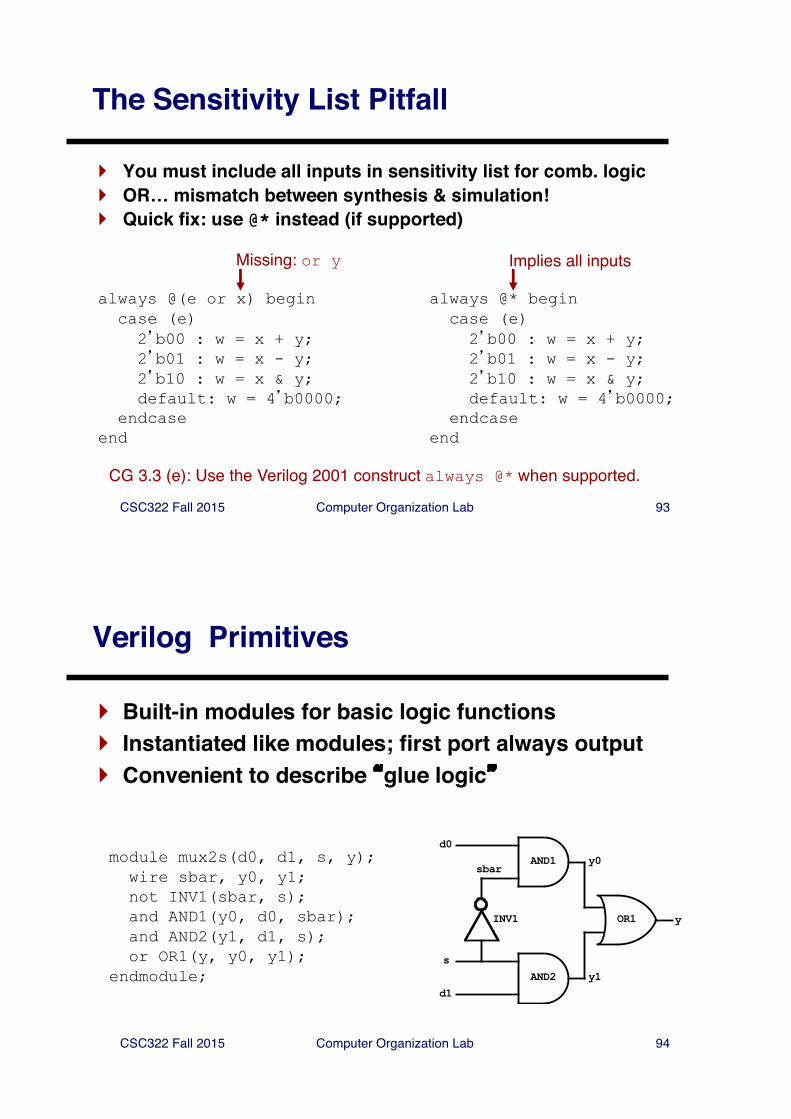
The Sensitivity List Pitfall
} You must include all inputs in sensitivity list for comb. logic} OR… mismatch between synthesis & simulation!} Quick fix: use @* instead (if supported)
Missing: or y
always @(e or x) begincase (e)2�b00 : w = x + y;2�b01 : w = x - y;2�b10 : w = x & y;default: w = 4�b0000;
endcaseend
always @* begincase (e)2�b00 : w = x + y;2�b01 : w = x - y;2�b10 : w = x & y;default: w = 4�b0000;
endcaseend
Implies all inputs
CG 3.3 (e): Use the Verilog 2001 construct always @* when supported.
CSC322 Fall 2015 Computer Organization Lab 94
Verilog Primitives
} Built-in modules for basic logic functions} Instantiated like modules; first port always output} Convenient to describe �glue logic�
module mux2s(d0, d1, s, y);wire sbar, y0, y1;not INV1(sbar, s);and AND1(y0, d0, sbar);and AND2(y1, d1, s);or OR1(y, y0, y1);
endmodule;
y
s
d1AND2
AND1
OR1INV1
d0y0
y1
sbar
CSC322 Fall 2015 Computer Organization Lab 95
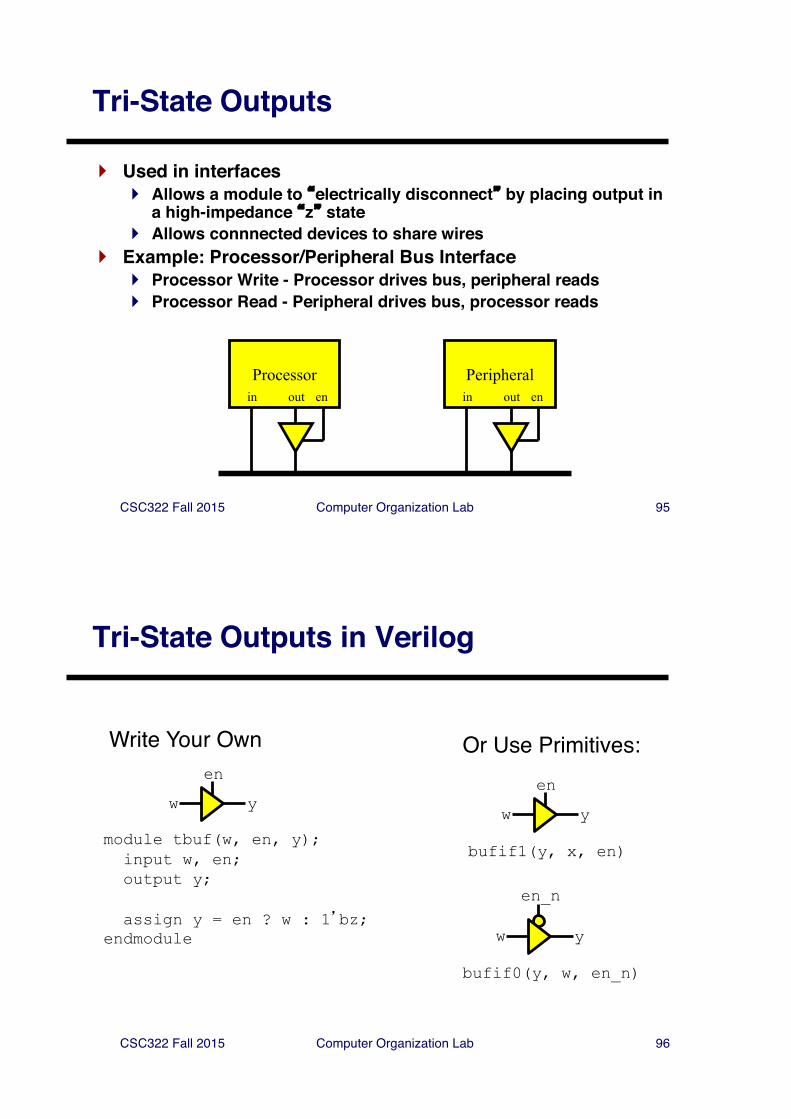
Tri-State Outputs
} Used in interfaces} Allows a module to �electrically disconnect� by placing output in
a high-impedance �z� state} Allows connnected devices to share wires
} Example: Processor/Peripheral Bus Interface} Processor Write - Processor drives bus, peripheral reads} Processor Read - Peripheral drives bus, processor reads
Processor Peripheralin out en in out en
CSC322 Fall 2015 Computer Organization Lab 96
Tri-State Outputs in Verilog
module tbuf(w, en, y);input w, en;output y;
assign y = en ? w : 1�bz;endmodule
w y
en
w y
en
bufif1(y, x, en)
w y
en_n
bufif0(y, w, en_n)
Write Your Own Or Use Primitives:
CSC322 Fall 2015 Computer Organization Lab 97
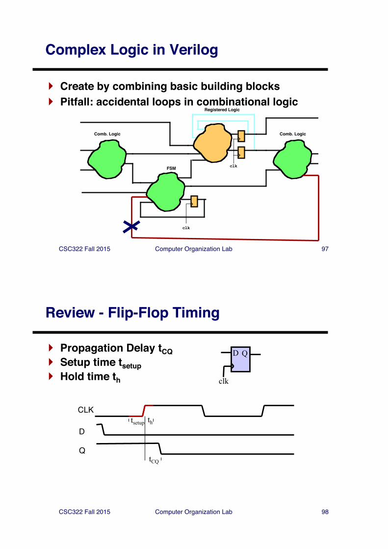
Complex Logic in Verilog
} Create by combining basic building blocks} Pitfall: accidental loops in combinational logic
clk
FSM
Comb. Logic
clk
Registered Logic
Comb. Logic
CSC322 Fall 2015 Computer Organization Lab 98
Review - Flip-Flop Timing
} Propagation Delay tCQ} Setup time tsetup} Hold time th
D Q
clk
Dtsetup th
CLK
QtCQ
CSC322 Fall 2015 Computer Organization Lab 99
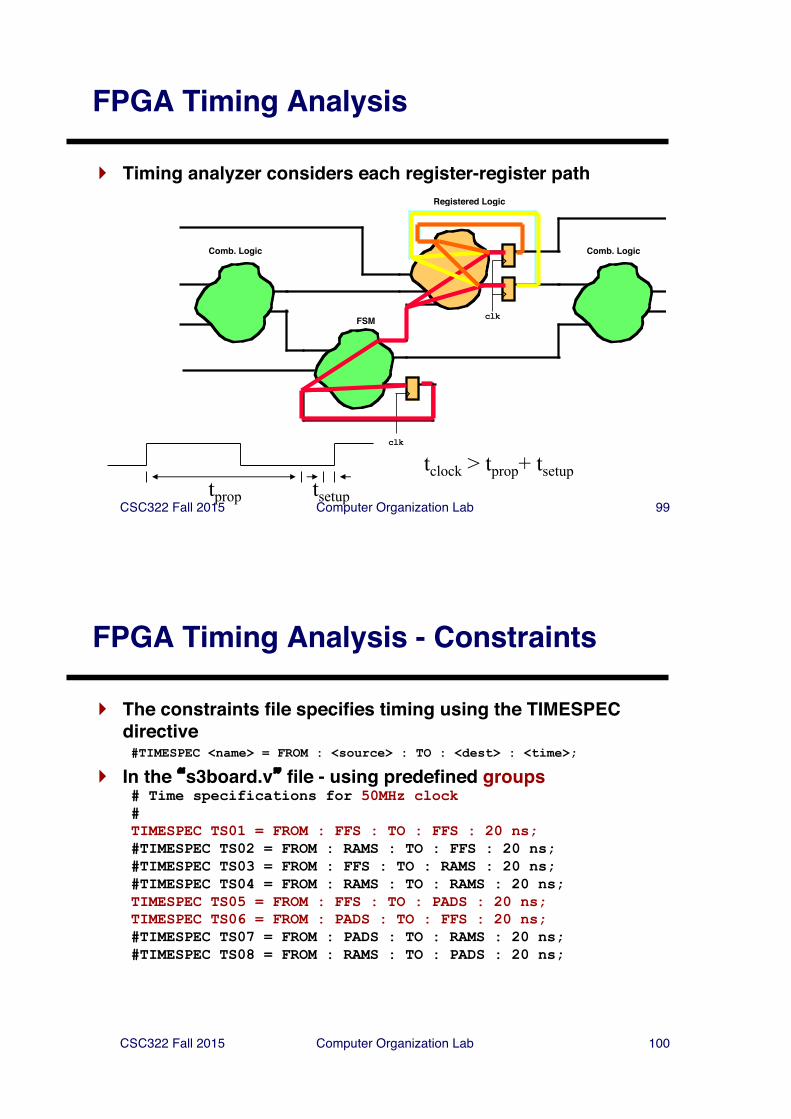
FPGA Timing Analysis
} Timing analyzer considers each register-register path
tprop tsetup
tclock > tprop+ tsetup
clk
FSM
Comb. Logic
clk
Registered Logic
Comb. Logic
CSC322 Fall 2015 Computer Organization Lab 100
FPGA Timing Analysis - Constraints
} The constraints file specifies timing using the TIMESPEC directive#TIMESPEC <name> = FROM : <source> : TO : <dest> : <time>;
} In the �s3board.v� file - using predefined groups# Time specifications for 50MHz clock#TIMESPEC TS01 = FROM : FFS : TO : FFS : 20 ns;#TIMESPEC TS02 = FROM : RAMS : TO : FFS : 20 ns;#TIMESPEC TS03 = FROM : FFS : TO : RAMS : 20 ns;#TIMESPEC TS04 = FROM : RAMS : TO : RAMS : 20 ns;TIMESPEC TS05 = FROM : FFS : TO : PADS : 20 ns;TIMESPEC TS06 = FROM : PADS : TO : FFS : 20 ns;#TIMESPEC TS07 = FROM : PADS : TO : RAMS : 20 ns; #TIMESPEC TS08 = FROM : RAMS : TO : PADS : 20 ns;
CSC322 Fall 2015 Computer Organization Lab 101
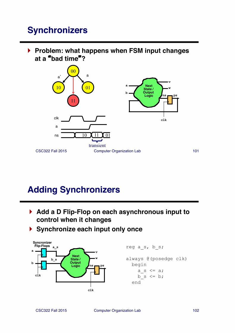
Synchronizers
} Problem: what happens when FSM input changes at a �bad time�?
00
10 01
a� a
0110
clk
a
ns
11
11
transient
avwNext
State / Output Logic psns
b
clk
CSC322 Fall 2015 Computer Organization Lab 102
Adding Synchronizers
} Add a D Flip-Flop on each asynchronous input to control when it changes
} Synchronize each input only once
a_svwNext
State / Output Logic psns
b_s
clk
clk
SyncronizerFlip-Flops
a
b
reg a_s, b_s;
always @(posedge clk)begina_s <= a;b_s <= b;
end
CSC322 Fall 2015 Computer Organization Lab 103
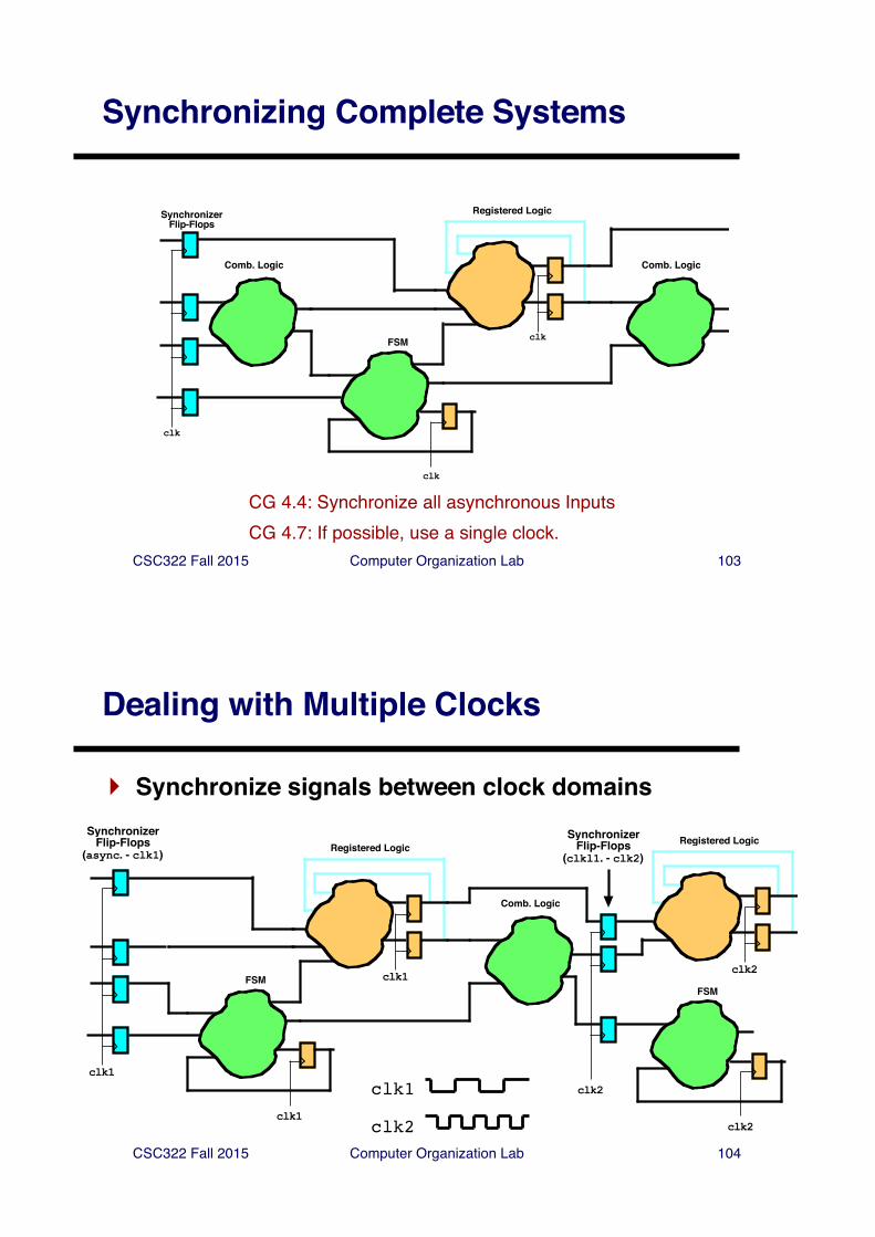
Synchronizing Complete Systems
CG 4.4: Synchronize all asynchronous Inputsclk
FSM
Comb. Logic
clk
Registered Logic
Comb. Logic
clk
SynchronizerFlip-Flops
CG 4.7: If possible, use a single clock.
CSC322 Fall 2015 Computer Organization Lab 104
Dealing with Multiple Clocks
} Synchronize signals between clock domains
clk1
clk2
clk1
Registered Logic
Comb. Logic
clk1
FSM
clk1
SynchronizerFlip-Flops
(async. - clk1)
clk2
Registered Logic
clk2
FSM
clk2
SynchronizerFlip-Flops
(clkl1. - clk2)
CSC322 Fall 2015 Computer Organization Lab 105
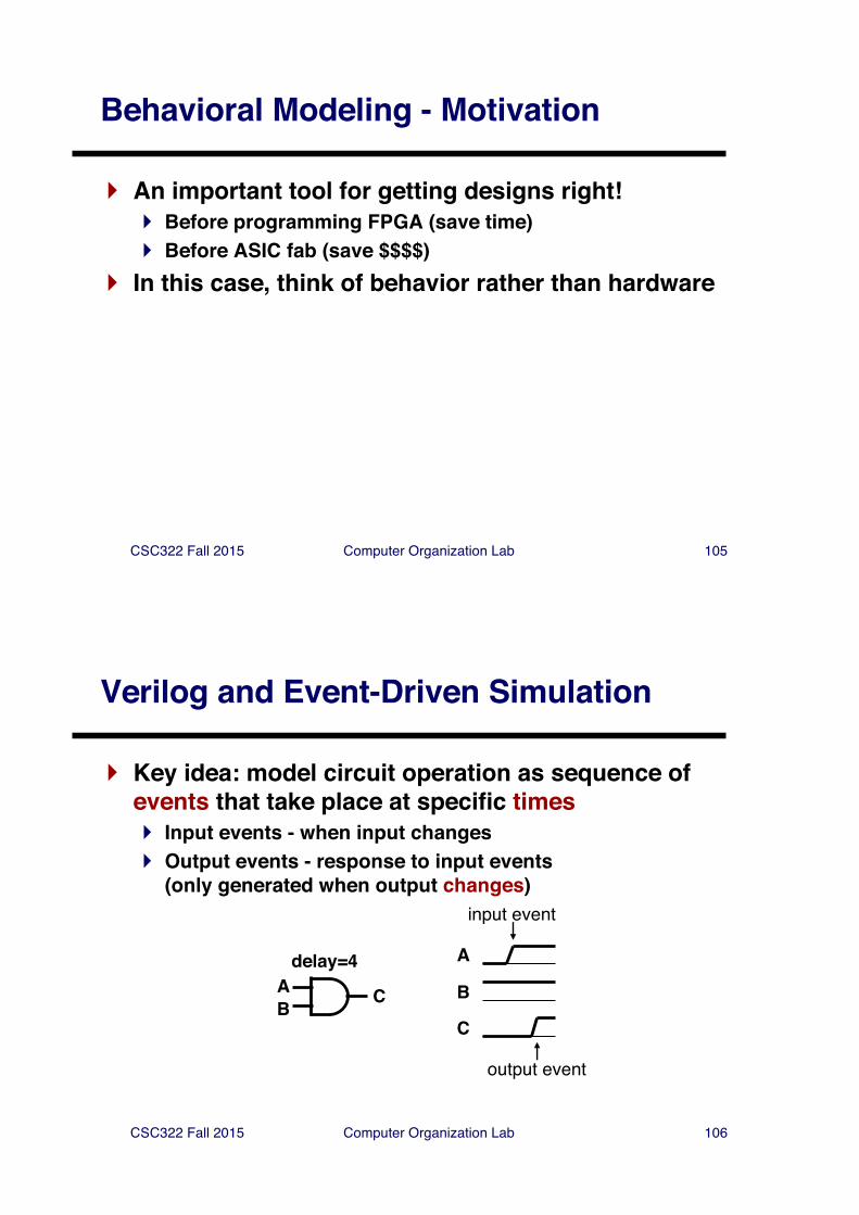
Behavioral Modeling - Motivation
} An important tool for getting designs right!} Before programming FPGA (save time)} Before ASIC fab (save $$$$)
} In this case, think of behavior rather than hardware
CSC322 Fall 2015 Computer Organization Lab 106
Verilog and Event-Driven Simulation
} Key idea: model circuit operation as sequence of events that take place at specific times} Input events - when input changes} Output events - response to input events
(only generated when output changes)
AB C
A
B
C
delay=4
input event
output event
CSC322 Fall 2015 Computer Organization Lab 107
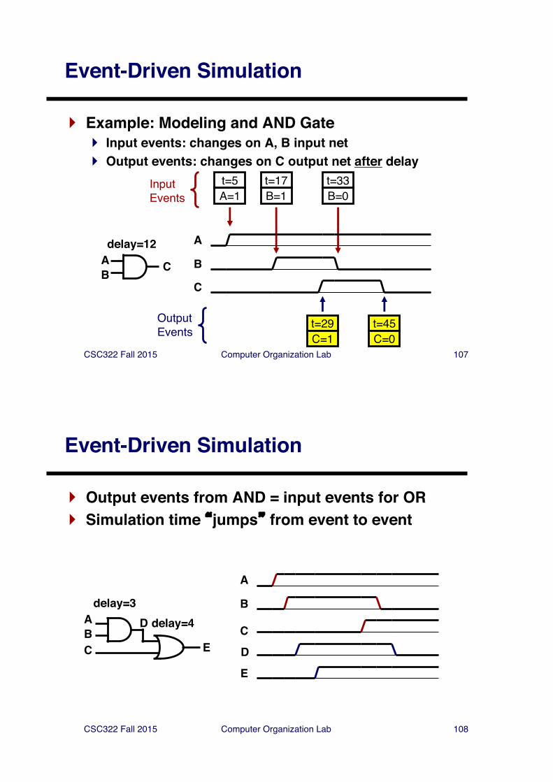
Event-Driven Simulation
} Example: Modeling and AND Gate} Input events: changes on A, B input net} Output events: changes on C output net after delay
AB C
A
B
C
t=5A=1
t=17B=1
t=33B=0
t=29C=1
delay=12
t=45C=0
InputEvents
OutputEvents
CSC322 Fall 2015 Computer Organization Lab 108
Event-Driven Simulation
} Output events from AND = input events for OR} Simulation time �jumps� from event to event
ABC
A
B
C
delay=3D
E
delay=4
DE
CSC322 Fall 2015 Computer Organization Lab 109
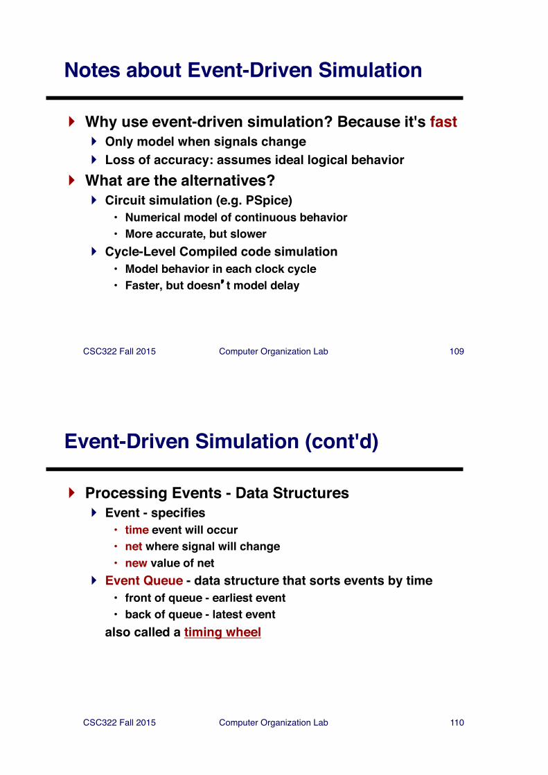
Notes about Event-Driven Simulation
} Why use event-driven simulation? Because it's fast} Only model when signals change} Loss of accuracy: assumes ideal logical behavior
} What are the alternatives?} Circuit simulation (e.g. PSpice)
• Numerical model of continuous behavior• More accurate, but slower
} Cycle-Level Compiled code simulation• Model behavior in each clock cycle• Faster, but doesn�t model delay
CSC322 Fall 2015 Computer Organization Lab 110
Event-Driven Simulation (cont'd)
} Processing Events - Data Structures} Event - specifies
• time event will occur• net where signal will change• new value of net
} Event Queue - data structure that sorts events by time• front of queue - earliest event• back of queue - latest event
also called a timing wheel
CSC322 Fall 2015 Computer Organization Lab 111
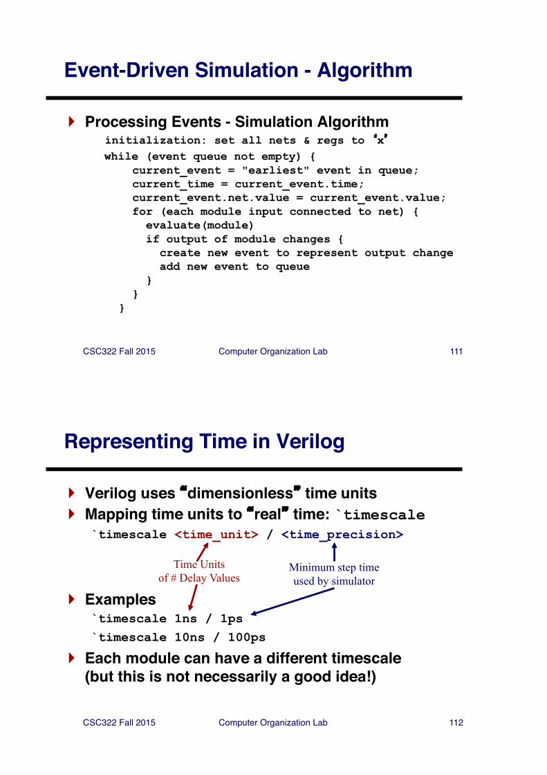
Event-Driven Simulation - Algorithm
} Processing Events - Simulation Algorithminitialization: set all nets & regs to �x�while (event queue not empty) {
current_event = "earliest" event in queue;current_time = current_event.time;current_event.net.value = current_event.value;for (each module input connected to net) {evaluate(module)if output of module changes {create new event to represent output changeadd new event to queue
}}
}
CSC322 Fall 2015 Computer Organization Lab 112
Representing Time in Verilog
} Verilog uses �dimensionless� time units} Mapping time units to �real� time: `timescale
`timescale <time_unit> / <time_precision>
} Examples`timescale 1ns / 1ps`timescale 10ns / 100ps
} Each module can have a different timescale(but this is not necessarily a good idea!)
Time Unitsof # Delay Values
Minimum step timeused by simulator
CSC322 Fall 2015 Computer Organization Lab 113
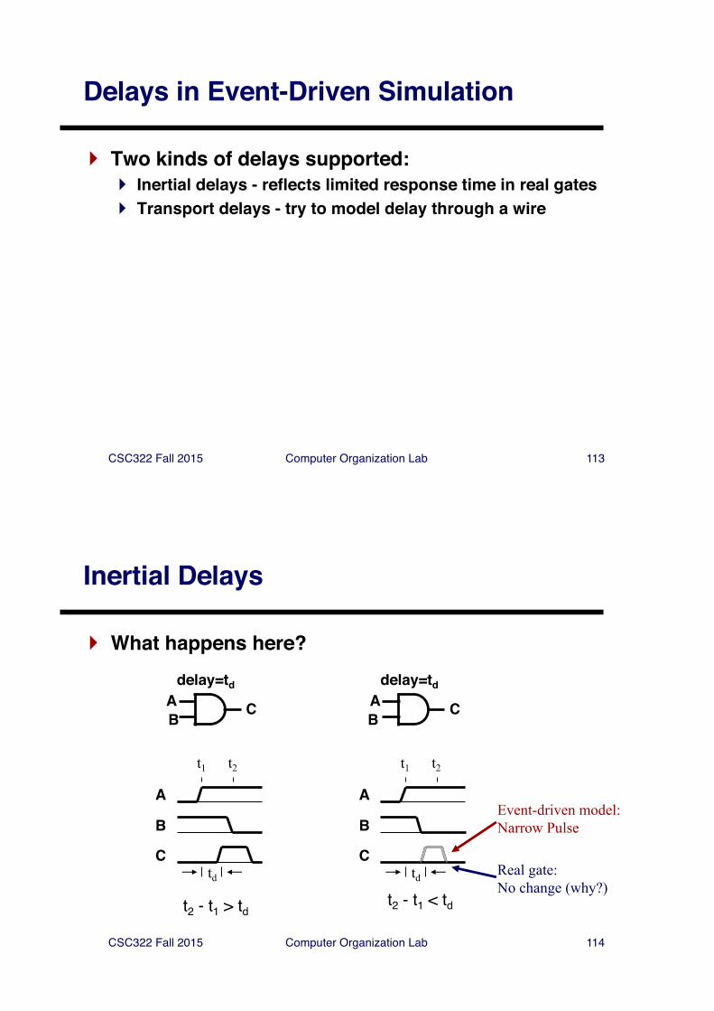
Delays in Event-Driven Simulation
} Two kinds of delays supported:} Inertial delays - reflects limited response time in real gates} Transport delays - try to model delay through a wire
CSC322 Fall 2015 Computer Organization Lab 114
Inertial Delays
} What happens here?
AB C
A
B
C
delay=td
t1 t2
td
t2 - t1 > td
AB C
A
B
C
delay=td
t1 t2
td
t2 - t1 < td
Event-driven model:Narrow Pulse
Real gate:No change (why?)
CSC322 Fall 2015 Computer Organization Lab 115
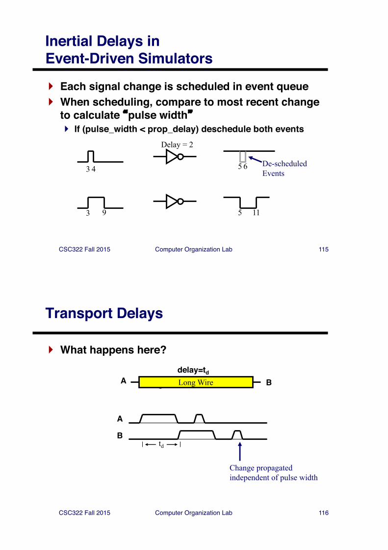
Inertial Delays in Event-Driven Simulators} Each signal change is scheduled in event queue} When scheduling, compare to most recent change
to calculate �pulse width�} If (pulse_width < prop_delay) deschedule both events
3
Delay = 2
54 6 De-scheduledEvents
3 59 11
CSC322 Fall 2015 Computer Organization Lab 116
Transport Delays
} What happens here?
A C
delay=td
Long Wire B
A
Btd
Change propagatedindependent of pulse width
CSC322 Fall 2015 Computer Organization Lab 117
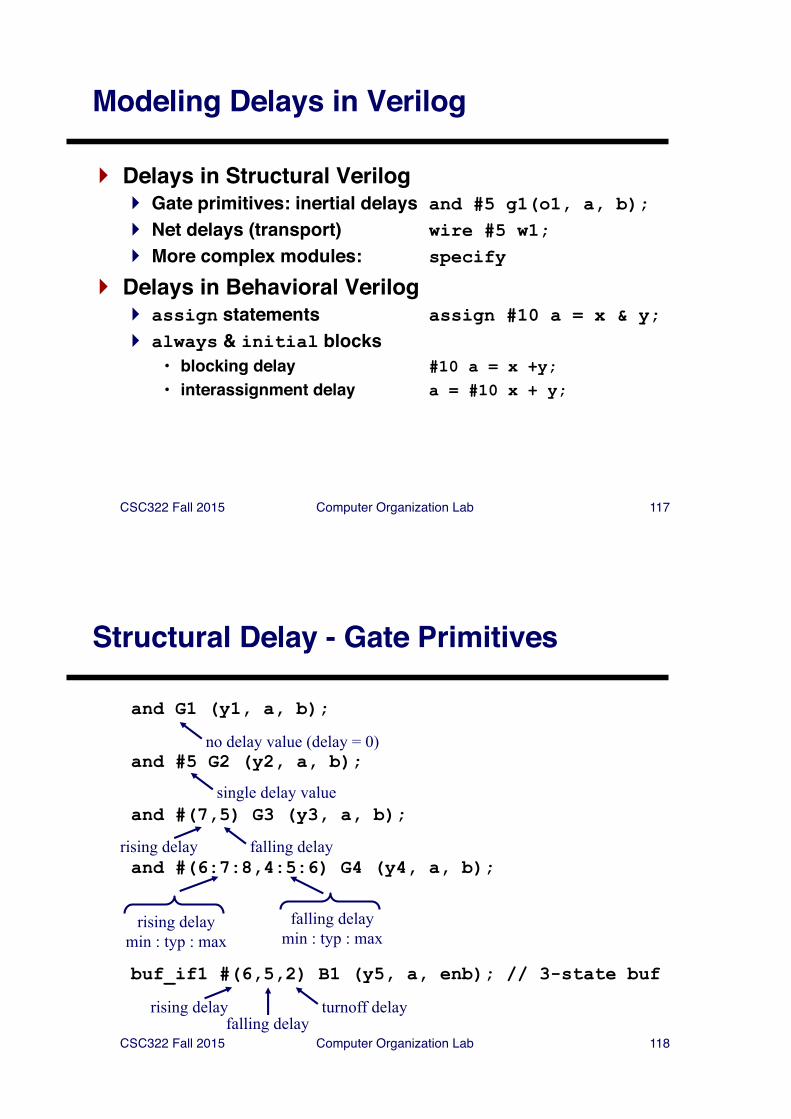
Modeling Delays in Verilog
} Delays in Structural Verilog} Gate primitives: inertial delays and #5 g1(o1, a, b);} Net delays (transport) wire #5 w1;} More complex modules: specify
} Delays in Behavioral Verilog} assign statements assign #10 a = x & y;} always & initial blocks
• blocking delay #10 a = x +y;• interassignment delay a = #10 x + y;
CSC322 Fall 2015 Computer Organization Lab 118
Structural Delay - Gate Primitives
and G1 (y1, a, b);
and #5 G2 (y2, a, b);
and #(7,5) G3 (y3, a, b);
and #(6:7:8,4:5:6) G4 (y4, a, b);
buf_if1 #(6,5,2) B1 (y5, a, enb); // 3-state buf
rising delay falling delay
single delay value
rising delaymin : typ : max
falling delaymin : typ : max
no delay value (delay = 0)
rising delay turnoff delayfalling delay
CSC322 Fall 2015 Computer Organization Lab 119
Delay in assign statements
} Delay specified as in structural specificationsassign #5 y1 = a & b;assign (#4,#5,$6) y2 = a & b;
} Specifies inertial delay
CSC322 Fall 2015 Computer Organization Lab 120
Delays in Behavioral Verilog
} �Parallel� statements for procedural modeling} always - for repeated activity
always @(sensitivity list) sequential_statementORalways sequential_statement
} initial - for one-time activity which starts in simulationinitial sequential_statement
} Combine with delay operators to create complex timing behavior
Event control statement
CSC322 Fall 2015 Computer Organization Lab 121
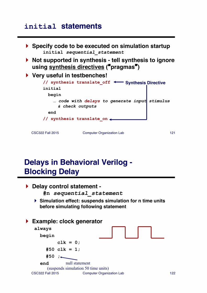
initial statements
} Specify code to be executed on simulation startupinitial sequential_statement
} Not supported in synthesis - tell synthesis to ignore using synthesis directives (�pragmas�)
} Very useful in testbenches!// synthesis translate_offinitialbegin… code with delays to generate input stimulus & check outputs
end // synthesis translate_on
Synthesis Directive
CSC322 Fall 2015 Computer Organization Lab 122
Delays in Behavioral Verilog -Blocking Delay} Delay control statement -
#n sequential_statement} Simulation effect: suspends simulation for n time units
before simulating following statement
} Example: clock generatoralways
beginclk = 0;
#50 clk = 1;#50 ;
end null statement(suspends simulation 50 time units)
CSC322 Fall 2015 Computer Organization Lab 123
Delays in Behavioral Verilog -Interassignment Delay} Key idea: unlike blocking delay, RHS is evaluated
before delay } With blocking assignments:
a = #5 b + c;d = a;
} With nonblocking assignments:a <= #5 b + c;d = a;
b + c evaluated; change in a scheduleddelayed until 5 time units elapse
b + c evaluated; change in a scheduledexecutes immediately; gets OLD value of a!
CSC322 Fall 2015 Computer Organization Lab 124
Simulation Time in Verilog: # and `timescale} `timescale controls simulation time
`timescale time_unit time_precision
`timescale 1ns 100ps
} # operator specifies delay in terms of time units`timescale 1ns 100ps#5 // delays 5*1ns = 5ns;
// rounds times to 100ps
`timescale 4ns 1ns#3 // delays 3*4ns = 12ns
// rounds times to 1ns
CSC322 Fall 2015 Computer Organization Lab 125
What happens when no delays are specified?} Each output event has a �delta� delay} Events processed in order of scheduling
CSC322 Fall 2015 Computer Organization Lab 126
Verilog functions
} Function Declaration:function [ range_or_type ] fname;
input_declarationsstatement
endfunction
} Return value: function body must assign:fname = expression;
} Function call: fname ( expression,… )
CSC322 Fall 2015 Computer Organization Lab 127
Verilog Functions (cont'd)
} Function characteristics:} returns a single value (default: 1 bit)} can have multiple input arguments (must have at least one)} can access signals in enclosing module} can call other functions, but not tasks} cannot call itself (no recursion)} executes in zero simulation time (no timing ops allowed)
} Synthesized as combinational logic(if proper subset is used)
CSC322 Fall 2015 Computer Organization Lab 128
Verilog Functions (cont'd)
} Function examples: function calc_parity;input [31:0] val;begin
calc_parity = ^val;endendfunction
function [15:0] average;input [15:0] a, b, c, d;begin
average = (a + b + c + d) >> 2;endendfunction;
CSC322 Fall 2015 Computer Organization Lab 129
Verilog Tasks
} Similar to procedures in VHDL, Pascal} Multiple input, output, and inout arguments} No explicit return value
(use output arguments instead)} No recursion allowed} Can "enable" (call) other tasks and functions} May contain delay, event, and timing control
statements (but not in synthesis)
CSC322 Fall 2015 Computer Organization Lab 130
Verilog Tasks (cont'd)
} Task example:task ReverseByte;input [7:0] a;output [7:0] ra;integer j;beginfor (j = 7; j >=0; j=j-1)ra[j] = a[7-j];
endend
endtask
// Adapted from "Verilog HDL Synthesis: A Practical// Primer", by J. Bhasker
CSC322 Fall 2015 Computer Organization Lab 131
System Tasks and Functions
} Tasks and functions defined for simulator control} All named starting with "$" (e.g., $monitor)} Standard - same for every simulator (almost)
} See Verilog Quick Reference Card, Section 8 for full list of system tasks
} Example system task: $display$display("format-string", expr1, …, exprn);
format-string - regular ASCII mixed with formatting characters%d - decimal, %b - binary, %h - hex, %t - time, etc.
other arguments: any expression, including wires and regs$display("Error at time %t: value is %h, expected %h",
$time, actual_value, expected_value);
CSC322 Fall 2015 Computer Organization Lab 132
Some useful System Tasks
} $time - return current simulation time } $monitor - print message when values change
$monitor("cs=%b, ns=%b", cs, ns)
} Simulation control tasks} $stop - interrupt simulation} $finish- terminate simulation
} Extensive file I/O also available
CSC322 Fall 2015 Computer Organization Lab 133
Verification
} Goal of verification:} Demonstrate functional correctness of a design} Attempt to find design errors} Attempt to show that design implements specification
} Importance of Verification} Costs of design errors can be high
(think �Pentium Floating-Point Error� ~ $300M!)} According to [1], verification consumes about 70% of
design effort
[1] J. Bergeron, Writing Testbenches: Functional Verification of HDL ModelsKluwer Academic Publishers, 2000.
CSC322 Fall 2015 Computer Organization Lab 134
Verification - Reconvergence Model
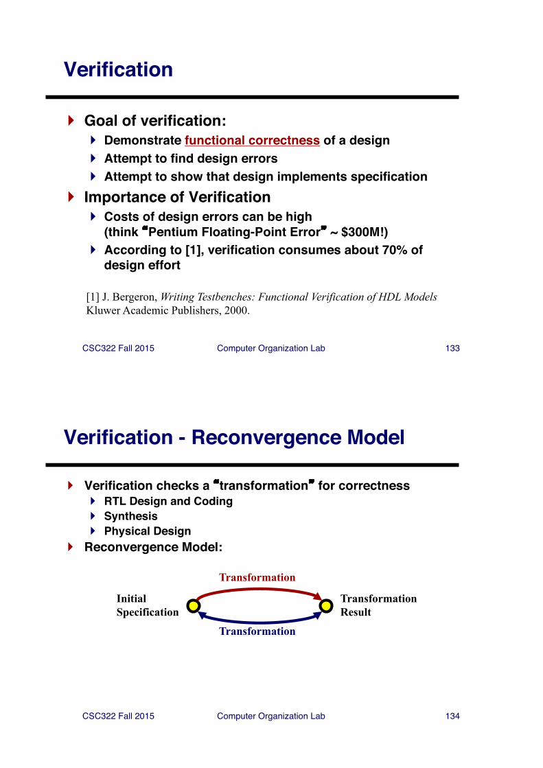
} Verification checks a �transformation� for correctness} RTL Design and Coding} Synthesis} Physical Design
} Reconvergence Model:
InitialSpecification
TransformationResult
Transformation
Transformation
CSC322 Fall 2015 Computer Organization Lab 135
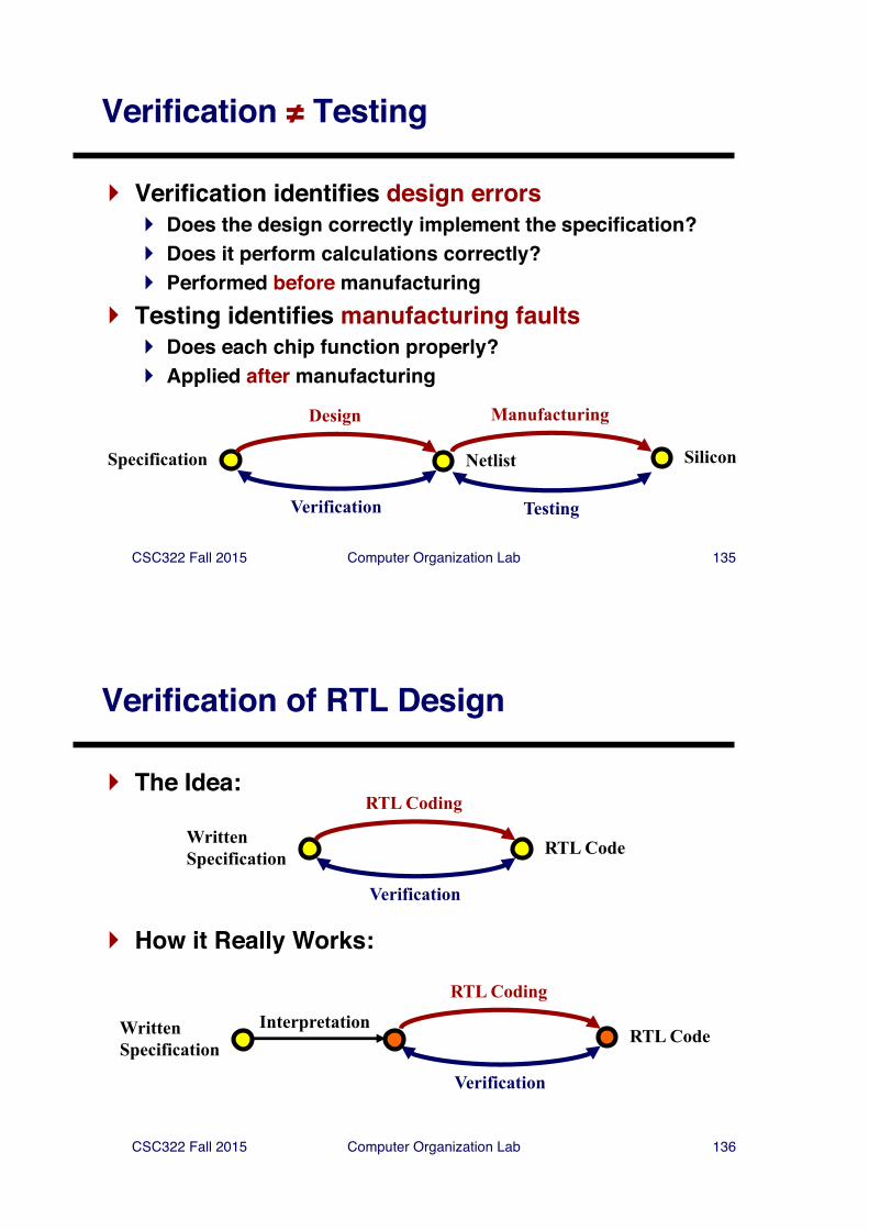
Verification ≠ Testing
} Verification identifies design errors} Does the design correctly implement the specification?} Does it perform calculations correctly?} Performed before manufacturing
} Testing identifies manufacturing faults} Does each chip function properly?} Applied after manufacturing
Specification Netlist
Design
Verification
Manufacturing
Testing
Silicon
CSC322 Fall 2015 Computer Organization Lab 136
Verification of RTL Design
} The Idea:
WrittenSpecification RTL Code
RTL Coding
Verification
} How it Really Works:
WrittenSpecification
RTL Code
RTL Coding
Verification
Interpretation
CSC322 Fall 2015 Computer Organization Lab 137
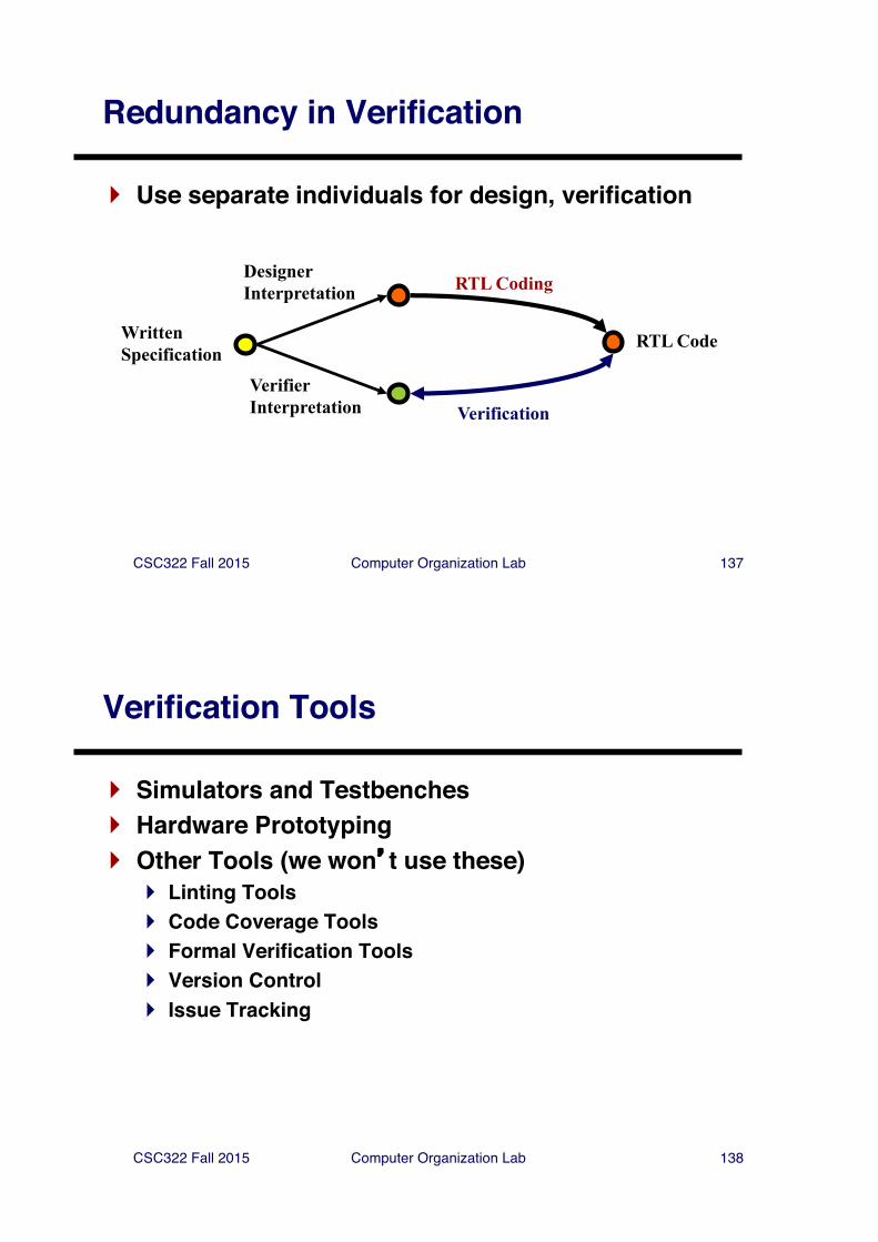
Redundancy in Verification
} Use separate individuals for design, verification
WrittenSpecification
Verification
RTL Code
RTL CodingDesignerInterpretation
VerifierInterpretation
CSC322 Fall 2015 Computer Organization Lab 138
Verification Tools
} Simulators and Testbenches} Hardware Prototyping} Other Tools (we won�t use these)
} Linting Tools} Code Coverage Tools} Formal Verification Tools} Version Control} Issue Tracking
CSC322 Fall 2015 Computer Organization Lab 139
Simulators
} Allow testing of system response to stimulus} Event-driven - including delay models} Cycle-level - one evaluation per clock cycle
} Simulation Tools} Waveform viewer} Testbenches - provide stimulus, check response} 3rd party models - simulate existing designs
• Full models• Bus-functional models
} Limitations of simulation} Can�t be exhaustive for non-trivial designs} Performance bottleneck
CSC322 Fall 2015 Computer Organization Lab 140
Testbenches
} A testbench (test fixture) is HDL code to verify a module} Apply input vectors to module inputs} Check module outputs} Report errors to user
} Why use a testbench instead of Verilogger TDE?} Portability - testbench will work on any HDL simulator} Automatic checking - don't have to interpret waveform} Expressability - can use the full semantics of HDL to:
• generate input vectors (possibly from input file)• check output vectors• control simulation
CSC322 Fall 2015 Computer Organization Lab 141
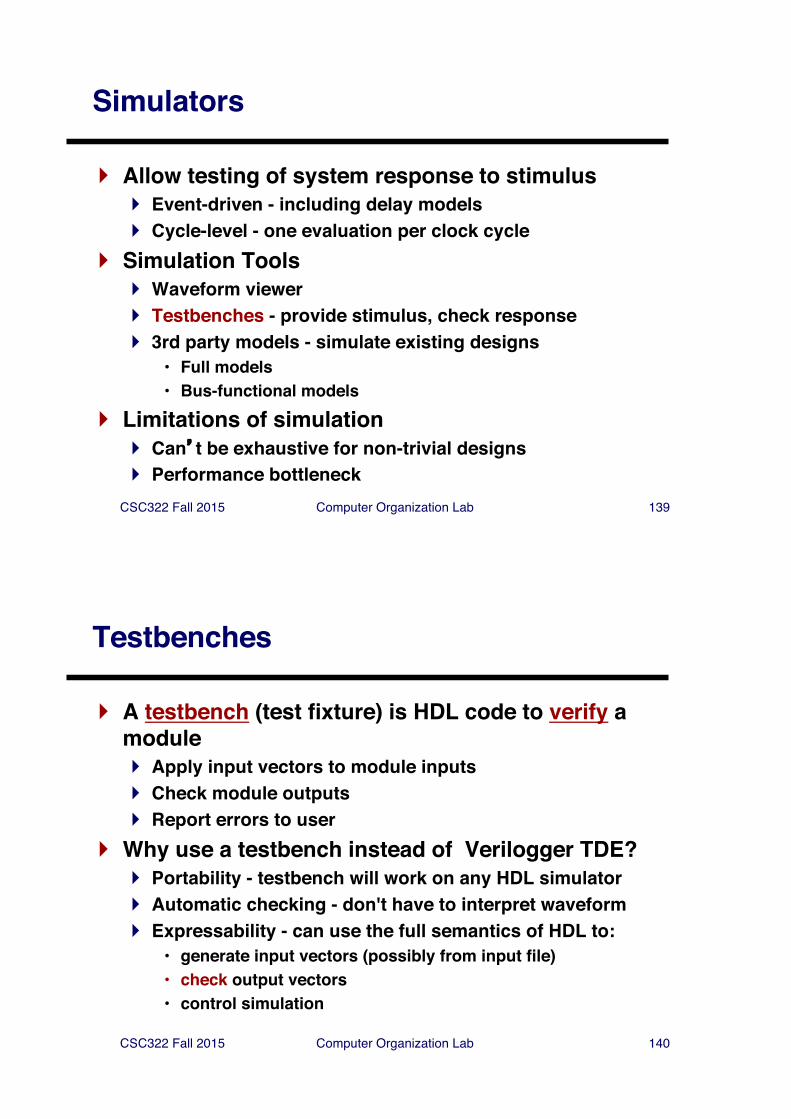
Coding Testbenches in Verilog HDL
Module Instance:DeviceUnder
Verification(DUV)
Testbench Module
CSC322 Fall 2015 Computer Organization Lab 142
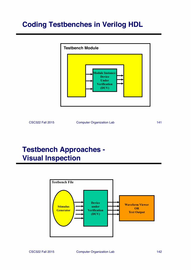
Testbench Approaches -Visual Inspection
Deviceunder
Verification(DUV)
StimulusGenerator
Testbench File
Waveform ViewerOR
Text Output
CSC322 Fall 2015 Computer Organization Lab 143
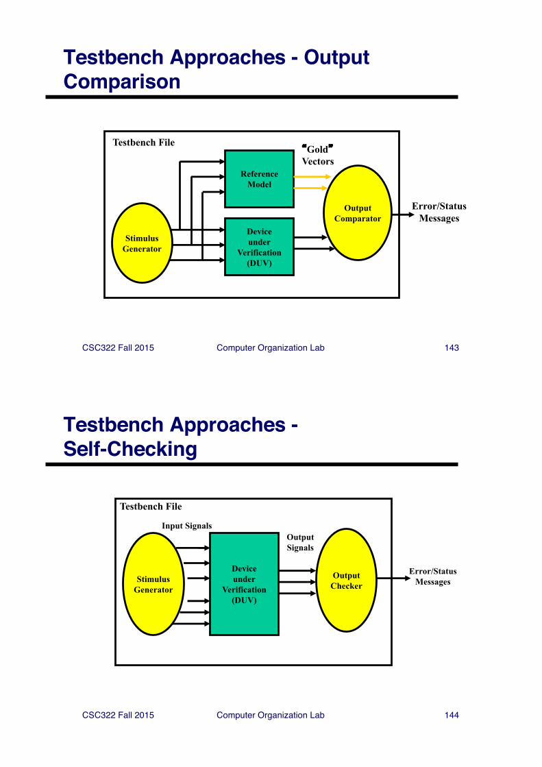
Testbench Approaches - Output Comparison
Deviceunder
Verification(DUV)
Testbench File
ReferenceModel
StimulusGenerator
OutputComparator
Error/Status Messages
�Gold�Vectors
CSC322 Fall 2015 Computer Organization Lab 144
Testbench Approaches -Self-Checking
Deviceunder
Verification(DUV)
StimulusGenerator
OutputSignals
Input Signals
Testbench File
OutputChecker
Error/StatusMessages
CSC322 Fall 2015 Computer Organization Lab 145
Comparing Approaches
} Visual inspection} Only practical for small designs} Automatic support: Verilogger timing diagram editor
} Output comparison} Effective when a good reference model is available} Used by ASIC foundries - �Gold� vectors are contractual
specification of a �functional� chip} Self-checking (our focus)
} Most difficult to code} Mandatory for large designs
CSC322 Fall 2015 Computer Organization Lab 146
Coding Testbenches
} Use simulation features of HDL} initial blocks} Functions & tasks} System Tasks
CSC322 Fall 2015 Computer Organization Lab 147
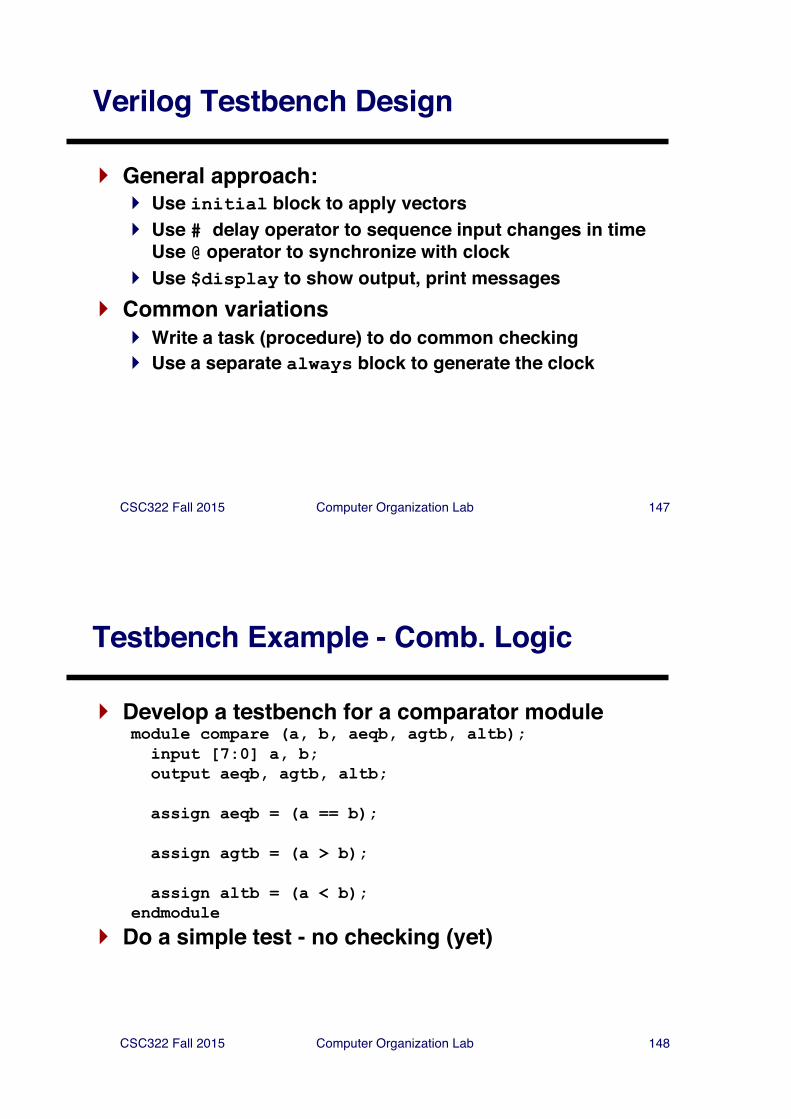
Verilog Testbench Design
} General approach:} Use initial block to apply vectors} Use # delay operator to sequence input changes in time
Use @ operator to synchronize with clock} Use $display to show output, print messages
} Common variations} Write a task (procedure) to do common checking} Use a separate always block to generate the clock
CSC322 Fall 2015 Computer Organization Lab 148
Testbench Example - Comb. Logic
} Develop a testbench for a comparator modulemodule compare (a, b, aeqb, agtb, altb);input [7:0] a, b;output aeqb, agtb, altb;
assign aeqb = (a == b);
assign agtb = (a > b);
assign altb = (a < b);endmodule
} Do a simple test - no checking (yet)
CSC322 Fall 2015 Computer Organization Lab 149
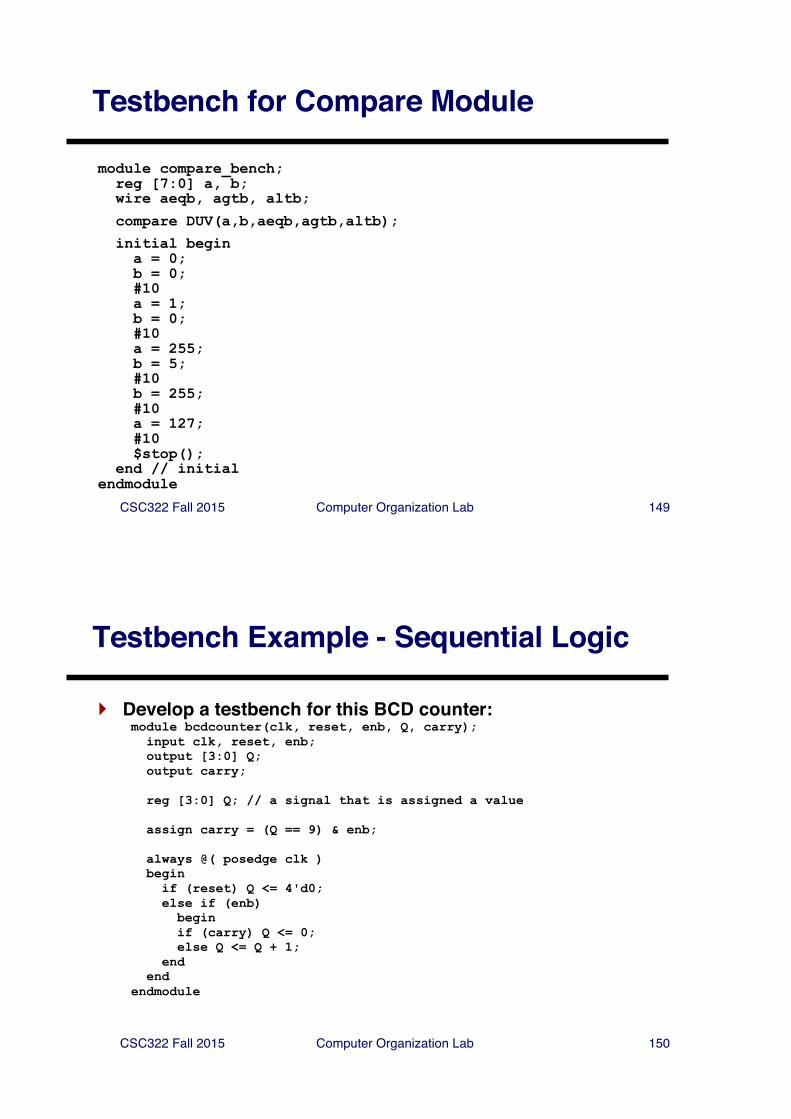
Testbench for Compare Module
module compare_bench;reg [7:0] a, b;wire aeqb, agtb, altb;
compare DUV(a,b,aeqb,agtb,altb);initial begina = 0;b = 0;#10 a = 1;b = 0;#10a = 255;b = 5;#10b = 255;#10a = 127;#10$stop();
end // initialendmodule
CSC322 Fall 2015 Computer Organization Lab 150
Testbench Example - Sequential Logic
} Develop a testbench for this BCD counter:module bcdcounter(clk, reset, enb, Q, carry);
input clk, reset, enb;output [3:0] Q;output carry;
reg [3:0] Q; // a signal that is assigned a value
assign carry = (Q == 9) & enb;
always @( posedge clk )begin
if (reset) Q <= 4'd0;else if (enb)
beginif (carry) Q <= 0;else Q <= Q + 1;
endend
endmodule
CSC322 Fall 2015 Computer Organization Lab 151
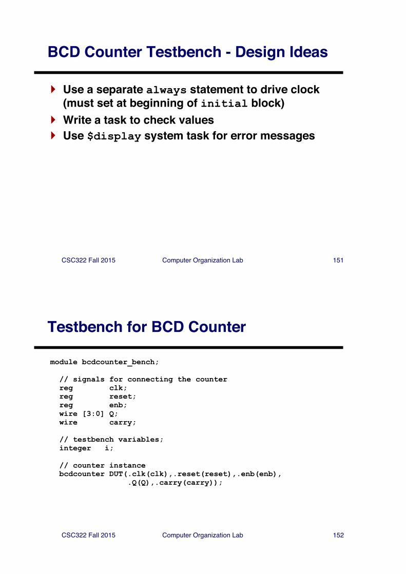
BCD Counter Testbench - Design Ideas
} Use a separate always statement to drive clock (must set at beginning of initial block)
} Write a task to check values} Use $display system task for error messages
CSC322 Fall 2015 Computer Organization Lab 152
Testbench for BCD Counter
module bcdcounter_bench;
// signals for connecting the counterreg clk;reg reset;reg enb;wire [3:0] Q;wire carry;
// testbench variables;integer i;
// counter instancebcdcounter DUT(.clk(clk),.reset(reset),.enb(enb),
.Q(Q),.carry(carry));
CSC322 Fall 2015 Computer Organization Lab 153
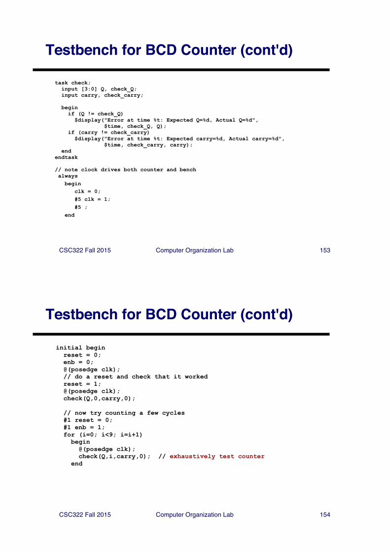
Testbench for BCD Counter (cont'd)
task check;input [3:0] Q, check_Q;input carry, check_carry;
beginif (Q != check_Q)
$display("Error at time %t: Expected Q=%d, Actual Q=%d",$time, check_Q, Q);
if (carry != check_carry)$display("Error at time %t: Expected carry=%d, Actual carry=%d",
$time, check_carry, carry);end
endtask
// note clock drives both counter and benchalways
beginclk = 0;#5 clk = 1;#5 ;
end
CSC322 Fall 2015 Computer Organization Lab 154
Testbench for BCD Counter (cont'd)
initial beginreset = 0;enb = 0;@(posedge clk);// do a reset and check that it workedreset = 1;@(posedge clk);check(Q,0,carry,0);
// now try counting a few cycles#1 reset = 0;#1 enb = 1;for (i=0; i<9; i=i+1)
begin@(posedge clk);check(Q,i,carry,0); // exhaustively test counter
end
CSC322 Fall 2015 Computer Organization Lab 155
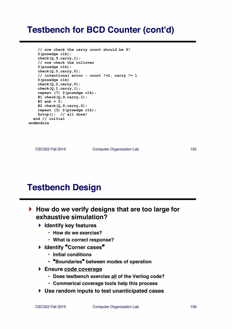
Testbench for BCD Counter (cont'd)
// now check the carry count should be 9!@(posedge clk);check(Q,9,carry,1);// now check the rollover@(posedge clk);check(Q,0,carry,0);// intentional error - count !=2, carry != 1@(posedge clk)check(Q,2,carry,0);check(Q,1,carry,1);repeat (7) @(posedge clk);#1 check(Q,9,carry,1);#5 enb = 0;#2 check(Q,9,carry,0);repeat (3) @(posedge clk);$stop(); // all done!
end // initialendmodule
CSC322 Fall 2015 Computer Organization Lab 156
Testbench Design
} How do we verify designs that are too large for exhaustive simulation?} Identify key features
• How do we exercise?• What is correct response?
} Identify �Corner cases�• Initial conditions• �Boundaries� between modes of operation
} Ensure code coverage• Does testbench exercise all of the Verilog code?• Commerical coverage tools help this process
} Use random inputs to test unanticipated cases
CSC322 Fall 2015 Computer Organization Lab 157
Verification of Large Designs
} Create a verification plan which specifies} Features necessary for first-time success
• Prioritization of features - essential vs. optional• Which features should be exercised• What the response should be
} Testcases to exercise features} Process for reporting and fixing bugs
} Implement testbenches for each testcase} Report bugs & fix} Big question: when are you done?
CSC322 Fall 2015 Computer Organization Lab 158
More about Testbenches
} Testbenches are essential in large designs} Design team may include hundreds of people, who work
on different subsystems} Testbenches allow semi-automatic checking when
different subsystems are changed (regression)} Chip design groups do this with "simulation farms"
CSC322 Fall 2015 Computer Organization Lab 159
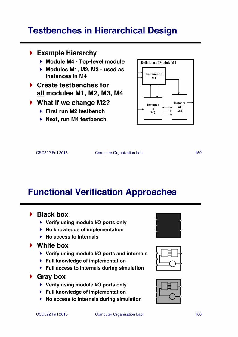
Instanceof
M2
InstanceofM3
Instance ofM1
Definition of Module M4
Testbenches in Hierarchical Design
} Example Hierarchy} Module M4 - Top-level module} Modules M1, M2, M3 - used as
instances in M4} Create testbenches for
all modules M1, M2, M3, M4} What if we change M2?
} First run M2 testbench} Next, run M4 testbench
CSC322 Fall 2015 Computer Organization Lab 160
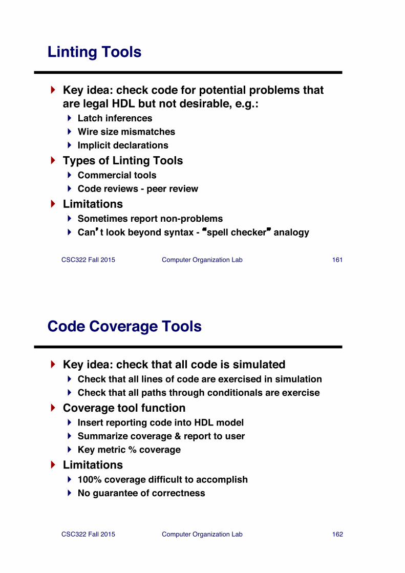
Functional Verification Approaches
} Black box} Verify using module I/O ports only} No knowledge of implementation} No access to internals
} White box} Verify using module I/O ports and internals} Full knowledge of implementation} Full access to internals during simulation
} Gray box} Verify using module I/O ports only} Full knowledge of implementation} No access to internals during simulation
CSC322 Fall 2015 Computer Organization Lab 161
Linting Tools
} Key idea: check code for potential problems that are legal HDL but not desirable, e.g.:} Latch inferences} Wire size mismatches} Implicit declarations
} Types of Linting Tools} Commercial tools} Code reviews - peer review
} Limitations} Sometimes report non-problems} Can�t look beyond syntax - �spell checker� analogy
CSC322 Fall 2015 Computer Organization Lab 162
Code Coverage Tools
} Key idea: check that all code is simulated} Check that all lines of code are exercised in simulation} Check that all paths through conditionals are exercise
} Coverage tool function} Insert reporting code into HDL model} Summarize coverage & report to user} Key metric % coverage
} Limitations} 100% coverage difficult to accomplish} No guarantee of correctness
CSC322 Fall 2015 Computer Organization Lab 163
Other Verification Tools
} Verification languages (e.g. e, Vera)} Used to specify and generate testbenches} Abstraction used to increase productivity} Focus on constrained random stimulus
} Revision control - used as in software engineering} Formal Verification
} Equivalence checking - prove that input, output are equivalent
} Model checking - Prove assertions concerning design properties, e.g.
• Reachability of states• Deadlock avoidance• Completion of transaction in an interface