Embed Size (px)
Citation preview
CSI 825A++SMD REWORK STATION
INSTRUCTION MANUAL
By: Circuit Specialists, Inc.
Rev. 072503
Key Features*Controlled by a CPU*A full Touch switch and a two-way digital display*Built in Vacuum system for removing the IC Chips after it has been de-soldered. (NOT ADESOLDERING PUMP)*Built in sleep mode when not used for 15min.
WARNING:WARNING: When you first remove this unit from the box. Before turning the unit on, YOU MUST RE-MOVE THE SCREW in the center of the bottom panel. This screw holds the pump in place duringtransportation.If this screw is not removed and the unit is turned on it may cause damage to your reworkstation.
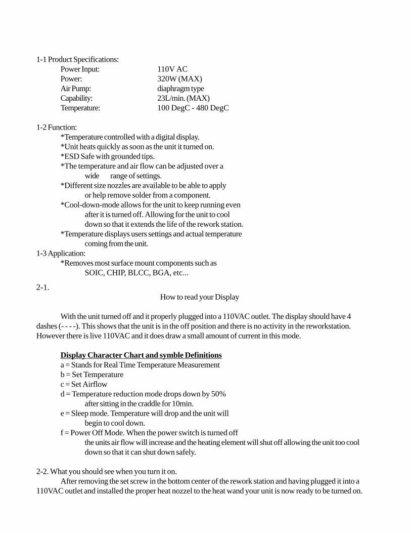
1-1 Product Specifications:Power Input: 110V ACPower: 320W (MAX)Air Pump: diaphragm typeCapability: 23L/min. (MAX)Temperature: 100 DegC - 480 DegC
1-2 Function:*Temperature controlled with a digital display.*Unit heats quickly as soon as the unit it turned on.*ESD Safe with grounded tips.*The temperature and air flow can be adjusted over a
wide range of settings.*Different size nozzles are available to be able to apply
or help remove solder from a component.*Cool-down-mode allows for the unit to keep running even
after it is turned off. Allowing for the unit to cooldown so that it extends the life of the rework station.
*Temperature displays users settings and actual temperaturecoming from the unit.
1-3 Application:*Removes most surface mount components such as
SOIC, CHIP, BLCC, BGA, etc...
2-1.How to read your Display
With the unit turned off and it properly plugged into a 110VAC outlet. The display should have 4dashes (- - - -). This shows that the unit is in the off position and there is no activity in the reworkstation.However there is live 110VAC and it does draw a small amount of current in this mode.
Display Character Chart and symble Definitionsa = Stands for Real Time Temperature Measurementb = Set Temperaturec = Set Airflowd = Temperature reduction mode drops down by 50%
after sitting in the craddle for 10min.e = Sleep mode. Temperature will drop and the unit will
begin to cool down.f = Power Off Mode. When the power switch is turned off
the units air flow will increase and the heating element will shut off allowing the unit too cooldown so that it can shut down safely.
2-2. What you should see when you turn it on.After removing the set screw in the bottom center of the rework station and having plugged it into a
110VAC outlet and installed the proper heat nozzel to the heat wand your unit is now ready to be turned on.
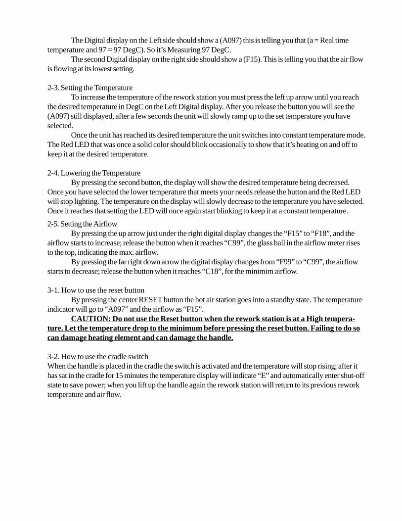
The Digital display on the Left side should show a (A097) this is telling you that (a = Real timetemperature and 97 = 97 DegC). So it’s Measuring 97 DegC.
The second Digital display on the right side should show a (F15). This is telling you that the air flowis flowing at its lowest setting.
2-3. Setting the TemperatureTo increase the temperature of the rework station you must press the left up arrow until you reach
the desired temperature in DegC on the Left Digital display. After you release the button you will see the(A097) still displayed, after a few seconds the unit will slowly ramp up to the set temperature you haveselected.
Once the unit has reached its desired temperature the unit switches into constant temperature mode.The Red LED that was once a solid color should blink occasionally to show that it’s heating on and off tokeep it at the desired temperature.
2-4. Lowering the TemperatureBy pressing the second button, the display will show the desired temperature being decreased.
Once you have selected the lower temperature that meets your needs release the button and the Red LEDwill stop lighting. The temperature on the display will slowly decrease to the temperature you have selected.Once it reaches that setting the LED will once again start blinking to keep it at a constant temperature.
2-5. Setting the AirflowBy pressing the up arrow just under the right digital display changes the “F15” to “F18”, and the
airflow starts to increase; release the button when it reaches “C99”, the glass ball in the airflow meter risesto the top, indicating the max. airflow.
By pressing the far right down arrow the digital display changes from “F99” to “C99”, the airflowstarts to decrease; release the button when it reaches “C18”, for the minimim airflow.
3-1. How to use the reset buttonBy pressing the center RESET button the hot air station goes into a standby state. The temperature
indicator will go to “A097” and the airflow as “F15”.CAUTION: Do not use the Reset button when the rework station is at a High tempera-
ture. Let the temperature drop to the minimum before pressing the reset button. Failing to do socan damage heating element and can damage the handle.
3-2. How to use the cradle switchWhen the handle is placed in the cradle the switch is activated and the temperature will stop rising; after ithas sat in the cradle for 15 minutes the temperature display will indicate “E” and automatically enter shut-offstate to save power; when you lift up the handle again the rework station will return to its previous reworktemperature and air flow.
4. Operating Instructions
4-1. Preparing your work before using your rework station.Select the FP Pick-up wire, The size of the IC should match the size of the Wire. You have two
choices, the 14mm or the 30mm.Select the proper nozzle size that will match the IC size. Installation of the nozzle should be done
before you turn on the rework station to avoid burning ones self accidently.
4-2. How to remove solder.Turn on the power switch. Set your Air Flow Speed first. Then set your temperature second. The
heat indicator lamp should be show a rise in the temperature.Place the FP Pick-up wire under the IC. If the pick-up wire is not the right size the metal is
bendable to the right size.
MELTING THE SOLDERNOTE: Do Not touch the PLN of the IC with the Nozzle of the rework station.Hold the Hot air handle facing down over the IC. Make sure and point the hot air outlets over the
area you wish to de solder. Wait until you see that the solder is completely melted and lift the FP pick-upwire thus removing the IC from the board.Shutting Down your rework station.
Once you have turned off the rework station the unit will go into a cool down mode before com-pletely turning off. The airflow will increase to full and continue to blow until the unit is safe to shut off.During this process you should not unplug the unit as it could cause the unit to over heat. Damage that mayoccur.
would be melting of the handle or damage to the controller board.When the temperature of the unit reaches below 100DegC The machine will automatically power
down, If the unit is not going to be used for some time it is suggested that the unit be unplugged from thewall outlet as the unit still uses some electricity even in the power off state.Clean the Remaining Solder
After the IC is removed from the board the remaining solder if any should be removed. Somesolutions are to use a Solder Absorber, Solder sucker or solder braid.Re soldering
Lay some solder paste on the area of the solder pads. Place the SMD in place on the board. Evenlyapply hot air to the SMD pins and wait until the solder paste has melted evenly. Once the IC is soldered inplace check to make sure that there are no solder balls or solder links between pins.
PRECAUTIONS:* Do not over tighten nozzle when installing it.* Be careful when working with high temperatures, DON'T USE THIS PRODUCT NEAR FLAM-MABLE GAS, PAPER, OR OTHER FLAMMABLE OBJECTS. The temperature of the nozzle and hotair are hot enough to burn a person SEVERELY. DO NOT touch or blow hot air on any part of your bodyor anyone else.* The first time the unit is started you may see and smell a small amount of smoke from the unit. Since it isnew the materials have not yet undergone any heat stresses, the unit should be taken outside and turned on.This is normal the first time it is used.
* After using the rework station remember to allow the unit to cool down before turning it off.* Never drop or sharply jolt the unit. The unit has in it quartz glass, which can break if the unit isdropped or jolted.* Do Not Disassemble the pump.* Disconnect the unit when you are not using it for long periods of time.
5. REPLACING THE HEATING ELEMENT5-1. Replacement PartsPart# Name/SpecificationA1144 110V/250W Heating Element
5-2. Replacing the heating elementLoosen the 3 screws in the handle. Then slide the hose down off of the base of the handle.Open the Handle. Disconnect the ground wire sleeve, and remove the pipe, In the pipe is
were the quartz glass and heating element are installed. Do not drop or handle it harshly. Loosenthe electric cable and take out the heating element. Install the new heating element and reconnectthe electric cable. Reconnect the ground wire. Assemble the handle in the reverse order.
Trouble Shooting:
Q: Why is the unit so noisy when I first start it up?A: The unit ships with a holding screw in the base of the unit. It must be removed.
Q: The unit vibrates to much.A: The unit ships with a holding screw to help keep the pumps rubber shock supports from coming looseduring shipping, however sometimes the supports still come loose and need to be reset. With the unitUnplugged remove the 6 screws 3 on each side and remove the cover. There are 4 rubber support legs thatshould be pulled through the base. If any are not they need to be pulled threw firmly.
Q: When I start to adjust the airflow by pressing the up arrow the ball goes to half. when i press it again itgoes to full, and still when I press it again it drops down to zero.A: The unit is okay. A calibrating adjustment may have been missed in the manufacturing process. Bypressing the air flow control up arrow further will allow you to control the air.
Q: The Unit will not heat up.A: The units heating element may have been damaged in shipping or the controller board is defective.