Embed Size (px)
Citation preview
Catalyst 6500 Series Switch Content Switching Module with OL-6238-01
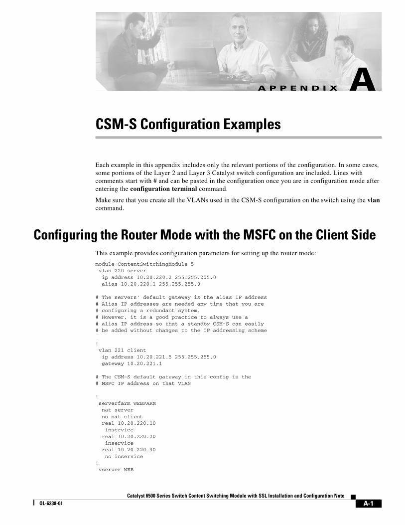
A P P E N D I X A
CSM-S Configuration ExamplesEach example in this appendix includes only the relevant portions of the configuration. In some cases, some portions of the Layer 2 and Layer 3 Catalyst switch configuration are included. Lines with comments start with # and can be pasted in the configuration once you are in configuration mode after entering the configuration terminal command.
Make sure that you create all the VLANs used in the CSM-S configuration on the switch using the vlan command.
Configuring the Router Mode with the MSFC on the Client SideThis example provides configuration parameters for setting up the router mode:
module ContentSwitchingModule 5 vlan 220 server ip address 10.20.220.2 255.255.255.0 alias 10.20.220.1 255.255.255.0
# The servers' default gateway is the alias IP address# Alias IP addresses are needed any time that you are# configuring a redundant system.# However, it is a good practice to always use a# alias IP address so that a standby CSM-S can easily# be added without changes to the IP addressing scheme
! vlan 221 client ip address 10.20.221.5 255.255.255.0 gateway 10.20.221.1
# The CSM-S default gateway in this config is the# MSFC IP address on that VLAN
! serverfarm WEBFARM nat server no nat client real 10.20.220.10 inservice real 10.20.220.20 inservice real 10.20.220.30 no inservice! vserver WEB
A-1SSL Installation and Configuration Note
Appendix A CSM-S Configuration ExamplesConfiguring the Router Mode with the MSFC on the Client Side
virtual 10.20.221.100 tcp www serverfarm WEBFARM persistent rebalance inservice
# "persistence rebalance" is effective ONLY when performing# L7 load balancing (parsing of URLs, cookies, header, ...)# and only for HTTP 1.1 connections.# It tells the CSM-S to parse and eventually make a new# load balancing decision for each GET within the same# TCP connection.
interface FastEthernet2/2 no ip address switchport switchport access vlan 220
# The above is the port that connects to the real servers
interface FastEthernet2/24 ip address 10.20.1.1 255.255.255.0
# The above is the interface that connects to the client side network
interface Vlan221 ip address 10.20.221.1 255.255.255.0
# The above is the MSFC interface for the internal VLAN used# for MSFC-CSM-S communication
This example shows the output of the show commands:
Cat6k-2# show module csm 5 arp
Internet Address Physical Interface VLAN Type Status-------------------------------------------------------------------- 10.20.220.1 00-02-FC-E1-68-EB 220 -ALIAS- local 10.20.220.2 00-02-FC-E1-68-EC 220 --SLB-- local 10.20.220.10 00-D0-B7-A0-81-D8 220 REAL up(0 misses) 10.20.221.1 00-02-FC-CB-70-0A 221 GATEWAY up(0 misses) 10.20.221.5 00-02-FC-E1-68-EC 221 --SLB-- local 10.20.220.20 00-D0-B7-A0-81-D8 220 REAL up(0 misses) 10.20.220.30 00-D0-B7-A0-81-D8 220 REAL up(0 misses) 10.20.221.100 00-02-FC-E1-68-EB 0 VSERVER local
Cat6k-2# show module csm 5 vlan detailvlan IP address IP mask type ---------------------------------------------------220 10.20.220.2 255.255.255.0 SERVER ALIASES IP address IP mask -------------------------------- 10.20.220.1 255.255.255.0 221 10.20.221.5 255.255.255.0 CLIENT GATEWAYS 10.20.221.1 Cat6k-2# Cat6k-2# show module csm 5 real
real server farm weight state conns/hits-------------------------------------------------------------------------10.20.220.10 WEBFARM 8 OPERATIONAL 0 10.20.220.20 WEBFARM 8 OPERATIONAL 0 10.20.220.30 WEBFARM 8 OUTOFSERVICE 0
A-2Catalyst 6500 Series Switch Content Switching Module with SSL Installation and Configuration Note
OL-6238-01
Appendix A CSM-S Configuration ExamplesConfiguring the Router Mode with the MSFC on the Client Side
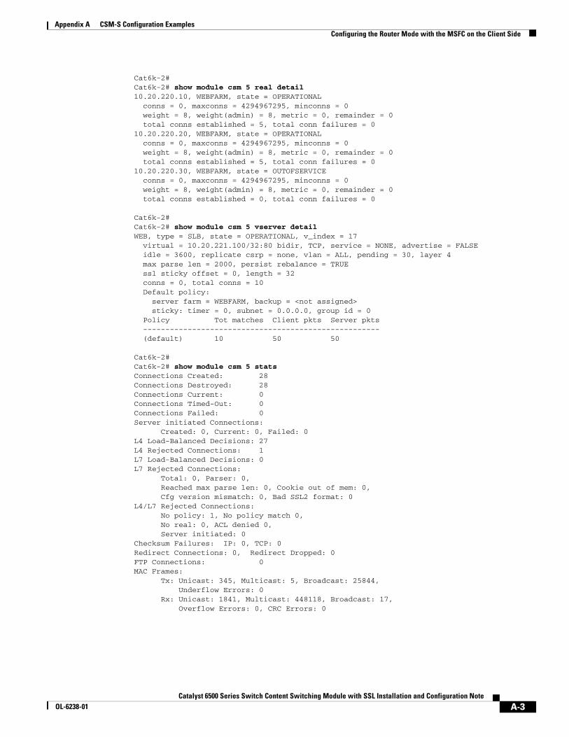
Cat6k-2# Cat6k-2# show module csm 5 real detail10.20.220.10, WEBFARM, state = OPERATIONAL conns = 0, maxconns = 4294967295, minconns = 0 weight = 8, weight(admin) = 8, metric = 0, remainder = 0 total conns established = 5, total conn failures = 010.20.220.20, WEBFARM, state = OPERATIONAL conns = 0, maxconns = 4294967295, minconns = 0 weight = 8, weight(admin) = 8, metric = 0, remainder = 0 total conns established = 5, total conn failures = 010.20.220.30, WEBFARM, state = OUTOFSERVICE conns = 0, maxconns = 4294967295, minconns = 0 weight = 8, weight(admin) = 8, metric = 0, remainder = 0 total conns established = 0, total conn failures = 0
Cat6k-2# Cat6k-2# show module csm 5 vserver detailWEB, type = SLB, state = OPERATIONAL, v_index = 17 virtual = 10.20.221.100/32:80 bidir, TCP, service = NONE, advertise = FALSE idle = 3600, replicate csrp = none, vlan = ALL, pending = 30, layer 4 max parse len = 2000, persist rebalance = TRUE ssl sticky offset = 0, length = 32 conns = 0, total conns = 10 Default policy: server farm = WEBFARM, backup = <not assigned> sticky: timer = 0, subnet = 0.0.0.0, group id = 0 Policy Tot matches Client pkts Server pkts ----------------------------------------------------- (default) 10 50 50
Cat6k-2# Cat6k-2# show module csm 5 statsConnections Created: 28Connections Destroyed: 28Connections Current: 0Connections Timed-Out: 0Connections Failed: 0Server initiated Connections: Created: 0, Current: 0, Failed: 0L4 Load-Balanced Decisions: 27L4 Rejected Connections: 1L7 Load-Balanced Decisions: 0L7 Rejected Connections: Total: 0, Parser: 0, Reached max parse len: 0, Cookie out of mem: 0, Cfg version mismatch: 0, Bad SSL2 format: 0L4/L7 Rejected Connections: No policy: 1, No policy match 0, No real: 0, ACL denied 0, Server initiated: 0Checksum Failures: IP: 0, TCP: 0Redirect Connections: 0, Redirect Dropped: 0FTP Connections: 0MAC Frames: Tx: Unicast: 345, Multicast: 5, Broadcast: 25844, Underflow Errors: 0 Rx: Unicast: 1841, Multicast: 448118, Broadcast: 17, Overflow Errors: 0, CRC Errors: 0
A-3Catalyst 6500 Series Switch Content Switching Module with SSL Installation and Configuration Note
OL-6238-01
Appendix A CSM-S Configuration ExamplesConfiguring the Bridged Mode with the MSFC on the Client Side
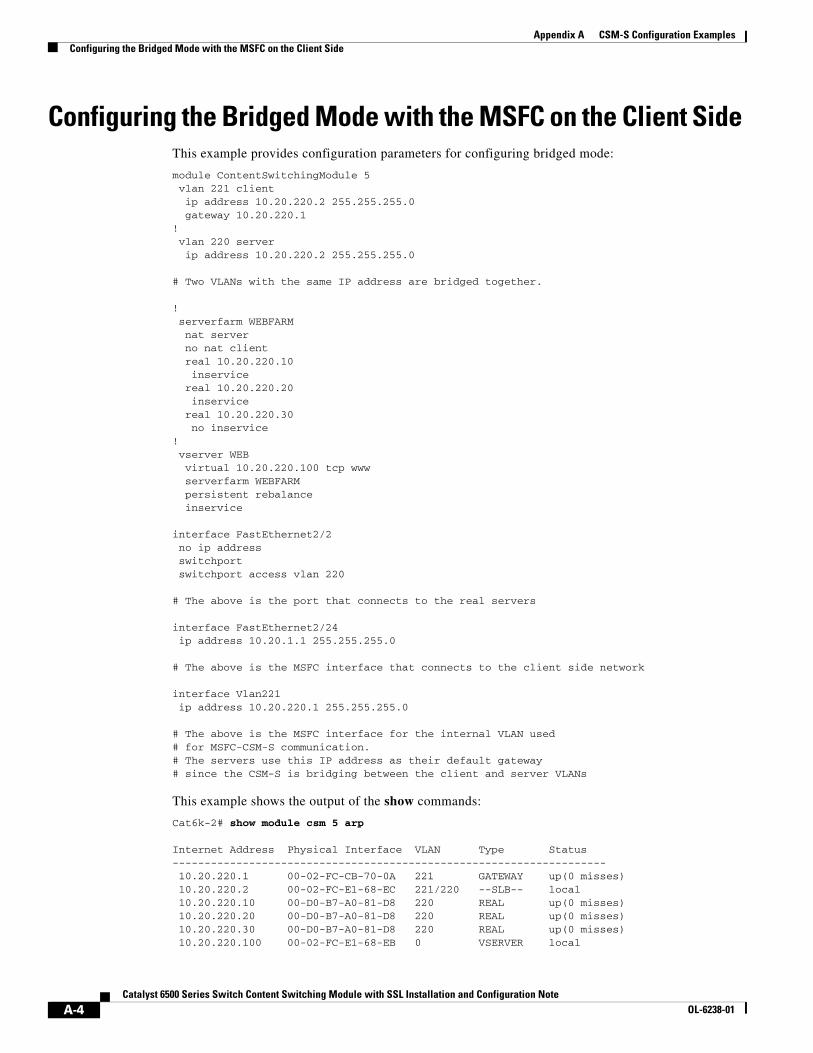
Configuring the Bridged Mode with the MSFC on the Client Side This example provides configuration parameters for configuring bridged mode:
module ContentSwitchingModule 5 vlan 221 client ip address 10.20.220.2 255.255.255.0 gateway 10.20.220.1! vlan 220 server ip address 10.20.220.2 255.255.255.0
# Two VLANs with the same IP address are bridged together.
! serverfarm WEBFARM nat server no nat client real 10.20.220.10 inservice real 10.20.220.20 inservice real 10.20.220.30 no inservice! vserver WEB virtual 10.20.220.100 tcp www serverfarm WEBFARM persistent rebalance inservice
interface FastEthernet2/2 no ip address switchport switchport access vlan 220
# The above is the port that connects to the real servers
interface FastEthernet2/24 ip address 10.20.1.1 255.255.255.0
# The above is the MSFC interface that connects to the client side network
interface Vlan221 ip address 10.20.220.1 255.255.255.0
# The above is the MSFC interface for the internal VLAN used# for MSFC-CSM-S communication.# The servers use this IP address as their default gateway# since the CSM-S is bridging between the client and server VLANs
This example shows the output of the show commands:
Cat6k-2# show module csm 5 arp
Internet Address Physical Interface VLAN Type Status-------------------------------------------------------------------- 10.20.220.1 00-02-FC-CB-70-0A 221 GATEWAY up(0 misses) 10.20.220.2 00-02-FC-E1-68-EC 221/220 --SLB-- local 10.20.220.10 00-D0-B7-A0-81-D8 220 REAL up(0 misses) 10.20.220.20 00-D0-B7-A0-81-D8 220 REAL up(0 misses) 10.20.220.30 00-D0-B7-A0-81-D8 220 REAL up(0 misses) 10.20.220.100 00-02-FC-E1-68-EB 0 VSERVER local
A-4Catalyst 6500 Series Switch Content Switching Module with SSL Installation and Configuration Note
OL-6238-01
Appendix A CSM-S Configuration ExamplesConfiguring the Probes
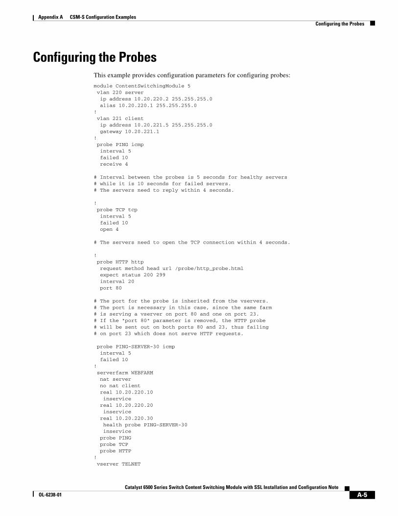
Configuring the ProbesThis example provides configuration parameters for configuring probes:
module ContentSwitchingModule 5 vlan 220 server ip address 10.20.220.2 255.255.255.0 alias 10.20.220.1 255.255.255.0! vlan 221 client ip address 10.20.221.5 255.255.255.0 gateway 10.20.221.1! probe PING icmp interval 5 failed 10 receive 4
# Interval between the probes is 5 seconds for healthy servers# while it is 10 seconds for failed servers.# The servers need to reply within 4 seconds.
! probe TCP tcp interval 5 failed 10 open 4
# The servers need to open the TCP connection within 4 seconds.
! probe HTTP http request method head url /probe/http_probe.html expect status 200 299 interval 20 port 80
# The port for the probe is inherited from the vservers.# The port is necessary in this case, since the same farm# is serving a vserver on port 80 and one on port 23.# If the "port 80" parameter is removed, the HTTP probe# will be sent out on both ports 80 and 23, thus failing# on port 23 which does not serve HTTP requests.
probe PING-SERVER-30 icmp interval 5 failed 10 ! serverfarm WEBFARM nat server no nat client real 10.20.220.10 inservice real 10.20.220.20 inservice real 10.20.220.30 health probe PING-SERVER-30 inservice probe PING probe TCP probe HTTP! vserver TELNET
A-5Catalyst 6500 Series Switch Content Switching Module with SSL Installation and Configuration Note
OL-6238-01
Appendix A CSM-S Configuration ExamplesConfiguring the Probes
virtual 10.20.221.100 tcp telnet serverfarm WEBFARM persistent rebalance inservice! vserver WEB virtual 10.20.221.100 tcp www serverfarm WEBFARM persistent rebalance inservice!
This example shows the output of the show commands:
Cat6k-2# show module csm 5 probe
probe type port interval retries failed open receive---------------------------------------------------------------------PING icmp 5 3 10 4 TCP tcp 5 3 10 4 HTTP http 80 20 3 300 10 10 PING-SERVER-30 icmp 5 3 10 10
Cat6k-2# show module csm 5 probe detailprobe type port interval retries failed open receive---------------------------------------------------------------------PING icmp 5 3 10 4 real vserver serverfarm policy status ------------------------------------------------------------------------------ 10.20.220.30:80 WEB WEBFARM (default) OPERABLE 10.20.220.20:80 WEB WEBFARM (default) OPERABLE 10.20.220.10:80 WEB WEBFARM (default) OPERABLE 10.20.220.30:23 TELNET WEBFARM (default) OPERABLE 10.20.220.20:23 TELNET WEBFARM (default) OPERABLE 10.20.220.10:23 TELNET WEBFARM (default) OPERABLETCP tcp 5 3 10 4 real vserver serverfarm policy status ------------------------------------------------------------------------------ 10.20.220.30:80 WEB WEBFARM (default) OPERABLE 10.20.220.20:80 WEB WEBFARM (default) OPERABLE 10.20.220.10:80 WEB WEBFARM (default) OPERABLE 10.20.220.30:23 TELNET WEBFARM (default) OPERABLE 10.20.220.20:23 TELNET WEBFARM (default) OPERABLE 10.20.220.10:23 TELNET WEBFARM (default) OPERABLEHTTP http 80 20 3 300 10 10 Probe Request: HEAD /probe/http_probe.html Expected Status Codes: 200 to 299 real vserver serverfarm policy status ------------------------------------------------------------------------------ 10.20.220.30:80 WEB WEBFARM (default) OPERABLE 10.20.220.20:80 WEB WEBFARM (default) FAILED 10.20.220.10:80 WEB WEBFARM (default) OPERABLE 10.20.220.30:80 TELNET WEBFARM (default) OPERABLE 10.20.220.20:80 TELNET WEBFARM (default) FAILED 10.20.220.10:80 TELNET WEBFARM (default) OPERABLEPING-SERVER-30 icmp 5 3 10 10 real vserver serverfarm policy status ------------------------------------------------------------------------------ 10.20.220.30:80 WEB WEBFARM (default) OPERABLE 10.20.220.30:23 TELNET WEBFARM (default) OPERABLE
A-6Catalyst 6500 Series Switch Content Switching Module with SSL Installation and Configuration Note
OL-6238-01

Appendix A CSM-S Configuration ExamplesConfiguring the Source NAT for Server-Originated Connections to the VIP
Cat6k-2# show module csm 5 real
real server farm weight state conns/hits-------------------------------------------------------------------------10.20.220.10 WEBFARM 8 OPERATIONAL 0 10.20.220.20 WEBFARM 8 PROBE_FAILED 0 10.20.220.30 WEBFARM 8 OPERATIONAL 0
Configuring the Source NAT for Server-Originated Connections to the VIP
This example shows a situation where the servers have open connections to the same VIP address that clients access. Because the servers are balanced back to themselves, the source NAT is required. To set the source NAT, use the vlan parameter in the virtual server configuration to distinguish the VLAN where the connection is originated. A different server farm is then used to handle server-originated connections. Source NAT is configured for that server farm. No source NAT is used for client-originated connections so that the servers can log the real client IPs.
Note You should use a similar configuration when the server-to-server load-balanced connections need to be supported with the source and destination servers located in the same VLAN.
module ContentSwitchingModule 5 vlan 220 server ip address 10.20.220.2 255.255.255.0 alias 10.20.220.1 255.255.255.0! vlan 221 client ip address 10.20.221.5 255.255.255.0 gateway 10.20.221.1! natpool POOL-1 10.20.220.99 10.20.220.99 netmask 255.255.255.0! serverfarm FARM nat server no nat client real 10.20.220.10 inservice real 10.20.220.20 inservice real 10.20.220.30 inservice! serverfarm FARM2 nat server nat client POOL-1 real 10.20.220.10 inservice real 10.20.220.20 inservice real 10.20.220.30 inservice! vserver FROM-CLIENTS virtual 10.20.221.100 tcp telnet vlan 221
A-7Catalyst 6500 Series Switch Content Switching Module with SSL Installation and Configuration Note
OL-6238-01
Appendix A CSM-S Configuration ExamplesConfiguring the Source NAT for Server-Originated Connections to the VIP
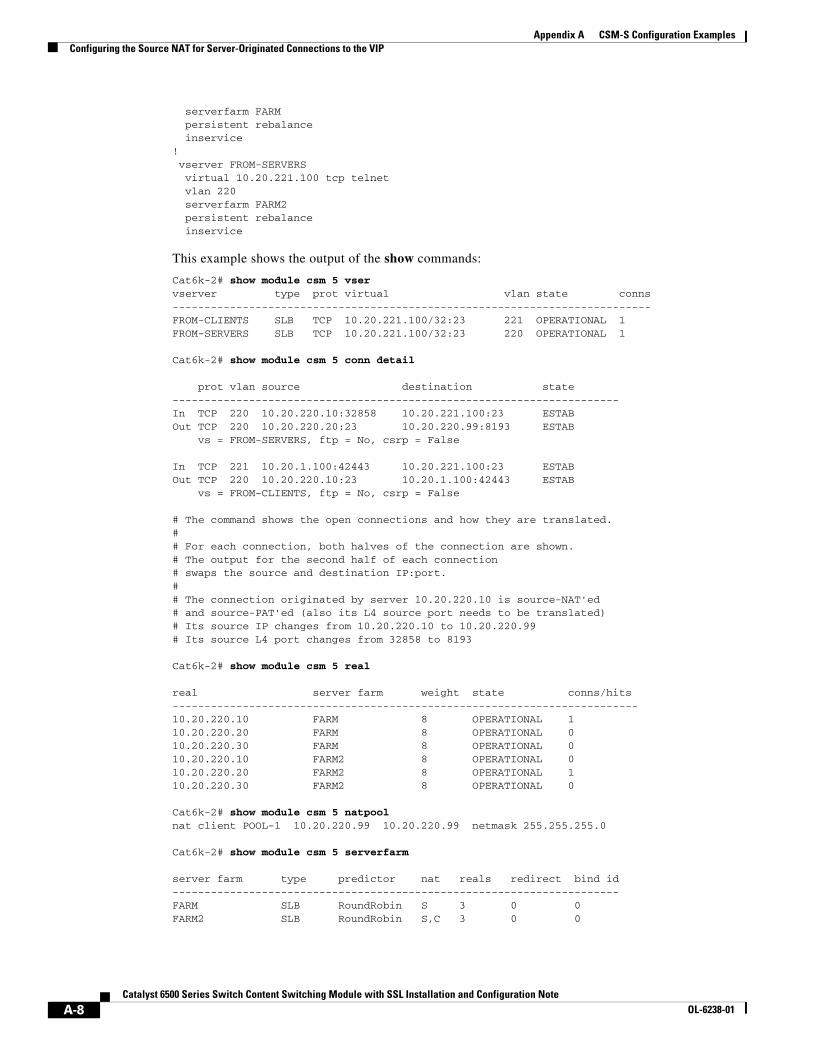
serverfarm FARM persistent rebalance inservice! vserver FROM-SERVERS virtual 10.20.221.100 tcp telnet vlan 220 serverfarm FARM2 persistent rebalance inservice
This example shows the output of the show commands:
Cat6k-2# show module csm 5 vser vserver type prot virtual vlan state conns---------------------------------------------------------------------------FROM-CLIENTS SLB TCP 10.20.221.100/32:23 221 OPERATIONAL 1 FROM-SERVERS SLB TCP 10.20.221.100/32:23 220 OPERATIONAL 1
Cat6k-2# show module csm 5 conn detail
prot vlan source destination state ----------------------------------------------------------------------In TCP 220 10.20.220.10:32858 10.20.221.100:23 ESTAB Out TCP 220 10.20.220.20:23 10.20.220.99:8193 ESTAB vs = FROM-SERVERS, ftp = No, csrp = False
In TCP 221 10.20.1.100:42443 10.20.221.100:23 ESTAB Out TCP 220 10.20.220.10:23 10.20.1.100:42443 ESTAB vs = FROM-CLIENTS, ftp = No, csrp = False
# The command shows the open connections and how they are translated.## For each connection, both halves of the connection are shown.# The output for the second half of each connection# swaps the source and destination IP:port.## The connection originated by server 10.20.220.10 is source-NAT'ed# and source-PAT'ed (also its L4 source port needs to be translated)# Its source IP changes from 10.20.220.10 to 10.20.220.99# Its source L4 port changes from 32858 to 8193
Cat6k-2# show module csm 5 real
real server farm weight state conns/hits-------------------------------------------------------------------------10.20.220.10 FARM 8 OPERATIONAL 1 10.20.220.20 FARM 8 OPERATIONAL 0 10.20.220.30 FARM 8 OPERATIONAL 0 10.20.220.10 FARM2 8 OPERATIONAL 0 10.20.220.20 FARM2 8 OPERATIONAL 1 10.20.220.30 FARM2 8 OPERATIONAL 0
Cat6k-2# show module csm 5 natpool nat client POOL-1 10.20.220.99 10.20.220.99 netmask 255.255.255.0
Cat6k-2# show module csm 5 serverfarm
server farm type predictor nat reals redirect bind id----------------------------------------------------------------------FARM SLB RoundRobin S 3 0 0 FARM2 SLB RoundRobin S,C 3 0 0
A-8Catalyst 6500 Series Switch Content Switching Module with SSL Installation and Configuration Note
OL-6238-01
Appendix A CSM-S Configuration ExamplesConfiguring Session Persistence (Stickiness)
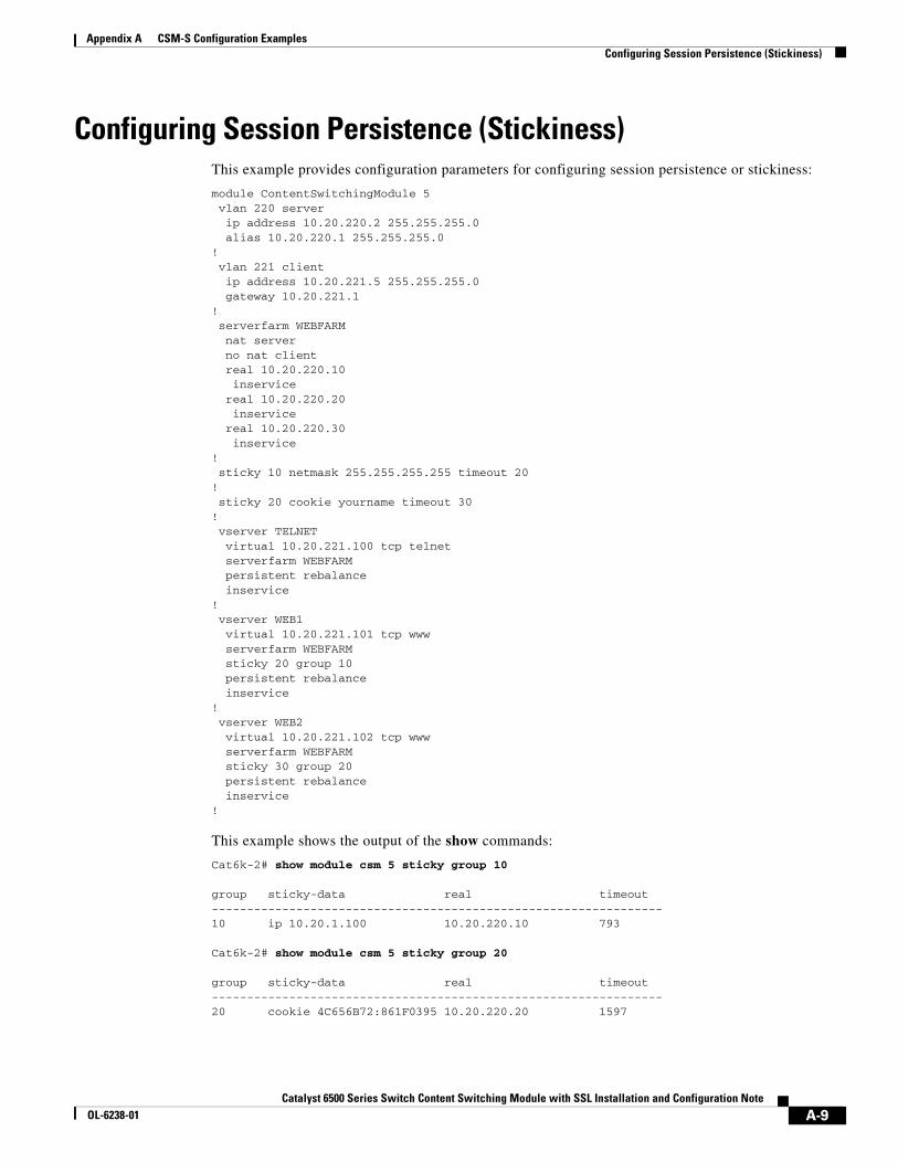
Configuring Session Persistence (Stickiness)This example provides configuration parameters for configuring session persistence or stickiness:
module ContentSwitchingModule 5 vlan 220 server ip address 10.20.220.2 255.255.255.0 alias 10.20.220.1 255.255.255.0! vlan 221 client ip address 10.20.221.5 255.255.255.0 gateway 10.20.221.1! serverfarm WEBFARM nat server no nat client real 10.20.220.10 inservice real 10.20.220.20 inservice real 10.20.220.30 inservice! sticky 10 netmask 255.255.255.255 timeout 20! sticky 20 cookie yourname timeout 30! vserver TELNET virtual 10.20.221.100 tcp telnet serverfarm WEBFARM persistent rebalance inservice! vserver WEB1 virtual 10.20.221.101 tcp www serverfarm WEBFARM sticky 20 group 10 persistent rebalance inservice! vserver WEB2 virtual 10.20.221.102 tcp www serverfarm WEBFARM sticky 30 group 20 persistent rebalance inservice!
This example shows the output of the show commands:
Cat6k-2# show module csm 5 sticky group 10
group sticky-data real timeout----------------------------------------------------------------10 ip 10.20.1.100 10.20.220.10 793
Cat6k-2# show module csm 5 sticky group 20
group sticky-data real timeout----------------------------------------------------------------20 cookie 4C656B72:861F0395 10.20.220.20 1597
A-9Catalyst 6500 Series Switch Content Switching Module with SSL Installation and Configuration Note
OL-6238-01
Appendix A CSM-S Configuration ExamplesConfiguring Direct Access to Servers in Router Mode
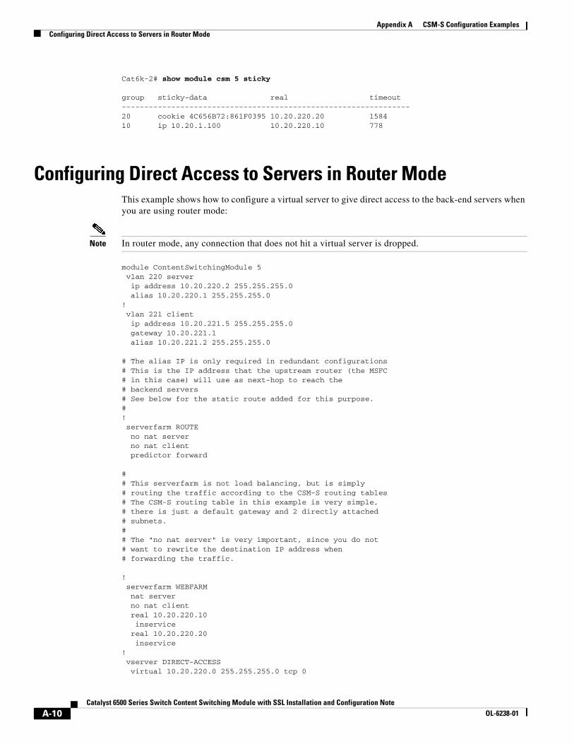
Cat6k-2# show module csm 5 sticky
group sticky-data real timeout----------------------------------------------------------------20 cookie 4C656B72:861F0395 10.20.220.20 1584 10 ip 10.20.1.100 10.20.220.10 778
Configuring Direct Access to Servers in Router ModeThis example shows how to configure a virtual server to give direct access to the back-end servers when you are using router mode:
Note In router mode, any connection that does not hit a virtual server is dropped.
module ContentSwitchingModule 5 vlan 220 server ip address 10.20.220.2 255.255.255.0 alias 10.20.220.1 255.255.255.0! vlan 221 client ip address 10.20.221.5 255.255.255.0 gateway 10.20.221.1 alias 10.20.221.2 255.255.255.0
# The alias IP is only required in redundant configurations# This is the IP address that the upstream router (the MSFC# in this case) will use as next-hop to reach the# backend servers# See below for the static route added for this purpose.#! serverfarm ROUTE no nat server no nat client predictor forward
## This serverfarm is not load balancing, but is simply# routing the traffic according to the CSM-S routing tables# The CSM-S routing table in this example is very simple,# there is just a default gateway and 2 directly attached# subnets.## The "no nat server" is very important, since you do not# want to rewrite the destination IP address when# forwarding the traffic.
! serverfarm WEBFARM nat server no nat client real 10.20.220.10 inservice real 10.20.220.20 inservice! vserver DIRECT-ACCESS virtual 10.20.220.0 255.255.255.0 tcp 0
A-10Catalyst 6500 Series Switch Content Switching Module with SSL Installation and Configuration Note
OL-6238-01
Appendix A CSM-S Configuration ExamplesConfiguring Direct Access to Servers in Router Mode
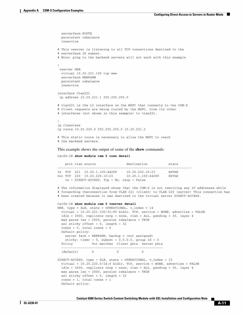
serverfarm ROUTE persistent rebalance inservice
# This vserver is listening to all TCP connections destined to the# serverfarm IP subnet.# Note: ping to the backend servers will not work with this example
! vserver WEB virtual 10.20.221.100 tcp www serverfarm WEBFARM persistent rebalance inservice
interface Vlan221 ip address 10.20.221.1 255.255.255.0
# vlan221 is the L3 interface on the MSFC that connects to the CSM-S# Client requests are being routed by the MSFC, from its other # interfaces (not shown in this example) to vlan221.
!ip classlessip route 10.20.220.0 255.255.255.0 10.20.221.2
# This static route is necessary to allow the MSFC to reach# the backend servers.
This example shows the output of some of the show commands:
Cat6k-2# show module csm 5 conn detail
prot vlan source destination state ----------------------------------------------------------------------In TCP 221 10.20.1.100:44268 10.20.220.10:23 ESTAB Out TCP 220 10.20.220.10:23 10.20.1.100:44268 ESTAB vs = DIRECT-ACCESS, ftp = No, csrp = False
# The information displayed shows that the CSM-S is not rewriting any IP addresses while# forwarding theconnection from VLAN 221 (client) to VLAN 220 (server) This connection has# been created because it was destined to the virtual server DIRECT-ACCESS.
Cat6k-2# show module csm 5 vserver detailWEB, type = SLB, state = OPERATIONAL, v_index = 14 virtual = 10.20.221.100/32:80 bidir, TCP, service = NONE, advertise = FALSE idle = 3600, replicate csrp = none, vlan = ALL, pending = 30, layer 4 max parse len = 2000, persist rebalance = TRUE ssl sticky offset = 0, length = 32 conns = 0, total conns = 0 Default policy: server farm = WEBFARM, backup = <not assigned> sticky: timer = 0, subnet = 0.0.0.0, group id = 0 Policy Tot matches Client pkts Server pkts ----------------------------------------------------- (default) 0 0 0
DIRECT-ACCESS, type = SLB, state = OPERATIONAL, v_index = 15 virtual = 10.20.220.0/24:0 bidir, TCP, service = NONE, advertise = FALSE idle = 3600, replicate csrp = none, vlan = ALL, pending = 30, layer 4 max parse len = 2000, persist rebalance = TRUE ssl sticky offset = 0, length = 32 conns = 1, total conns = 1 Default policy:
A-11Catalyst 6500 Series Switch Content Switching Module with SSL Installation and Configuration Note
OL-6238-01

Appendix A CSM-S Configuration ExamplesConfiguring Server-to-Server Load-Balanced Connections
server farm = ROUTE, backup = <not assigned> sticky: timer = 0, subnet = 0.0.0.0, group id = 0 Policy Tot matches Client pkts Server pkts ----------------------------------------------------- (default) 1 48 35
Configuring Server-to-Server Load-Balanced ConnectionsThis example shows a CSM-S configuration with three VLANs, one client, and two server VLANs. This configuration allows server-to-server load-balanced connections. There is no need for the source NAT because the source and destination servers are in separate VLANs.
module ContentSwitchingModule 5 vlan 220 server ip address 10.20.220.2 255.255.255.0 alias 10.20.220.1 255.255.255.0! vlan 221 client ip address 10.20.221.5 255.255.255.0 gateway 10.20.221.1! vlan 210 server ip address 10.20.210.2 255.255.255.0 alias 10.20.210.1 255.255.255.0! serverfarm TIER-1 nat server no nat client real 10.20.210.10 inservice real 10.20.210.20 inservice! serverfarm TIER-2 nat server no nat client real 10.20.220.10 inservice real 10.20.220.20 inservice! vserver VIP1 virtual 10.20.221.100 tcp telnet vlan 221 serverfarm TIER-1 persistent rebalance inservice! vserver VIP2 virtual 10.20.210.100 tcp telnet vlan 210 serverfarm TIER-2 persistent rebalance inservice!
A-12Catalyst 6500 Series Switch Content Switching Module with SSL Installation and Configuration Note
OL-6238-01
Appendix A CSM-S Configuration ExamplesConfiguring Route Health Injection
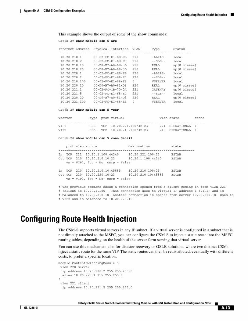
This example shows the output of some of the show commands:
Cat6k-2# show module csm 5 arp
Internet Address Physical Interface VLAN Type Status-------------------------------------------------------------------- 10.20.210.1 00-02-FC-E1-68-EB 210 -ALIAS- local 10.20.210.2 00-02-FC-E1-68-EC 210 --SLB-- local 10.20.210.10 00-D0-B7-A0-68-5D 210 REAL up(0 misses) 10.20.210.20 00-D0-B7-A0-68-5D 210 REAL up(0 misses) 10.20.220.1 00-02-FC-E1-68-EB 220 -ALIAS- local 10.20.220.2 00-02-FC-E1-68-EC 220 --SLB-- local 10.20.210.100 00-02-FC-E1-68-EB 0 VSERVER local 10.20.220.10 00-D0-B7-A0-81-D8 220 REAL up(0 misses) 10.20.221.1 00-02-FC-CB-70-0A 221 GATEWAY up(0 misses) 10.20.221.5 00-02-FC-E1-68-EC 221 --SLB-- local 10.20.220.20 00-D0-B7-A0-81-D8 220 REAL up(0 misses) 10.20.221.100 00-02-FC-E1-68-EB 0 VSERVER local
Cat6k-2# show module csm 5 vser
vserver type prot virtual vlan state conns---------------------------------------------------------------------------VIP1 SLB TCP 10.20.221.100/32:23 221 OPERATIONAL 1 VIP2 SLB TCP 10.20.210.100/32:23 210 OPERATIONAL 1
Cat6k-2# show module csm 5 conn detail
prot vlan source destination state ----------------------------------------------------------------------In TCP 221 10.20.1.100:44240 10.20.221.100:23 ESTAB Out TCP 210 10.20.210.10:23 10.20.1.100:44240 ESTAB vs = VIP1, ftp = No, csrp = False
In TCP 210 10.20.210.10:45885 10.20.210.100:23 ESTAB Out TCP 220 10.20.220.10:23 10.20.210.10:45885 ESTAB vs = VIP2, ftp = No, csrp = False
# The previous command shows a connection opened from a client coming in from VLAN 221# (client is 10.20.1.100). That connection goes to virtual IP address 1 (VIP1) and is# balanced to 10.20.210.10. Another connection is opened from server 10.20.210.10, goes to# VIP2 and is balanced to 10.20.220.10
Configuring Route Health InjectionThe CSM-S supports virtual servers in any IP subnet. If a virtual server is configured in a subnet that is not directly attached to the MSFC, you can configure the CSM-S to inject a static route into the MSFC routing tables, depending on the health of the server farm serving that virtual server.
You can use this mechanism also for disaster recovery or GSLB solutions, where two distinct CSMs inject a static route for the same VIP. The static routes can then be redistributed, eventually with different costs, to prefer a specific location.
module ContentSwitchingModule 5 vlan 220 server ip address 10.20.220.2 255.255.255.0 alias 10.20.220.1 255.255.255.0! vlan 221 client ip address 10.20.221.5 255.255.255.0
A-13Catalyst 6500 Series Switch Content Switching Module with SSL Installation and Configuration Note
OL-6238-01
Appendix A CSM-S Configuration ExamplesConfiguring Route Health Injection
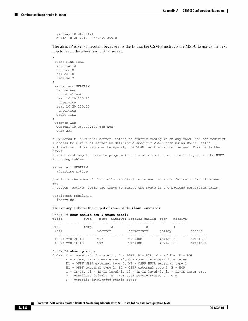
gateway 10.20.221.1 alias 10.20.221.2 255.255.255.0
The alias IP is very important because it is the IP that the CSM-S instructs the MSFC to use as the next hop to reach the advertised virtual server.
! probe PING icmp interval 2 retries 2 failed 10 receive 2 ! serverfarm WEBFARM nat server no nat client real 10.20.220.10 inservice real 10.20.220.20 inservice probe PING! vserver WEB virtual 10.20.250.100 tcp www vlan 221
# By default, a virtual server listens to traffic coming in on any VLAN. You can restrict# access to a virtual server by defining a specific VLAN. When using Route Health# Injection, it is required to specify the VLAN for the virtual server. This tells the CSM-S# which next-hop it needs to program in the static route that it will inject in the MSFC# routing tables.
serverfarm WEBFARM advertise active
# This is the command that tells the CSM-S to inject the route for this virtual server. The# option "active" tells the CSM-S to remove the route if the backend serverfarm fails.
persistent rebalance inservice
This example shows the output of some of the show commands:
Cat6k-2# show module csm 5 probe detailprobe type port interval retries failed open receive---------------------------------------------------------------------PING icmp 2 2 10 2 real vserver serverfarm policy status ------------------------------------------------------------------------------ 10.20.220.20:80 WEB WEBFARM (default) OPERABLE 10.20.220.10:80 WEB WEBFARM (default) OPERABLE
Cat6k-2# show ip routeCodes: C - connected, S - static, I - IGRP, R - RIP, M - mobile, B - BGP D - EIGRP, EX - EIGRP external, O - OSPF, IA - OSPF inter area N1 - OSPF NSSA external type 1, N2 - OSPF NSSA external type 2 E1 - OSPF external type 1, E2 - OSPF external type 2, E - EGP i - IS-IS, L1 - IS-IS level-1, L2 - IS-IS level-2, ia - IS-IS inter area * - candidate default, U - per-user static route, o - ODR P - periodic downloaded static route
A-14Catalyst 6500 Series Switch Content Switching Module with SSL Installation and Configuration Note
OL-6238-01
Appendix A CSM-S Configuration ExamplesConfiguring Route Health Injection
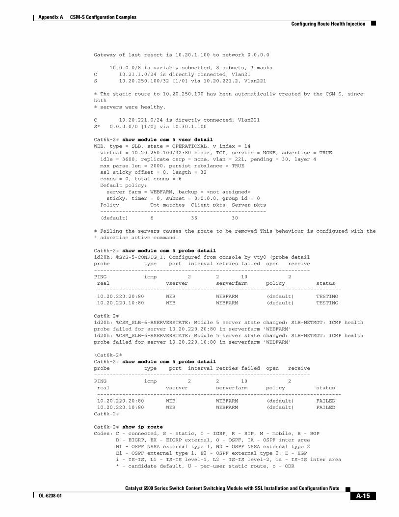
Gateway of last resort is 10.20.1.100 to network 0.0.0.0
10.0.0.0/8 is variably subnetted, 8 subnets, 3 masksC 10.21.1.0/24 is directly connected, Vlan21S 10.20.250.100/32 [1/0] via 10.20.221.2, Vlan221
# The static route to 10.20.250.100 has been automatically created by the CSM-S, since both# servers were healthy.
C 10.20.221.0/24 is directly connected, Vlan221S* 0.0.0.0/0 [1/0] via 10.30.1.100
Cat6k-2# show module csm 5 vser detailWEB, type = SLB, state = OPERATIONAL, v_index = 14 virtual = 10.20.250.100/32:80 bidir, TCP, service = NONE, advertise = TRUE idle = 3600, replicate csrp = none, vlan = 221, pending = 30, layer 4 max parse len = 2000, persist rebalance = TRUE ssl sticky offset = 0, length = 32 conns = 0, total conns = 6 Default policy: server farm = WEBFARM, backup = <not assigned> sticky: timer = 0, subnet = 0.0.0.0, group id = 0 Policy Tot matches Client pkts Server pkts ----------------------------------------------------- (default) 6 36 30
# Failing the servers causes the route to be removed This behaviour is configured with the# advertise active command.
Cat6k-2# show module csm 5 probe detail1d20h: %SYS-5-CONFIG_I: Configured from console by vty0 (probe detailprobe type port interval retries failed open receive---------------------------------------------------------------------PING icmp 2 2 10 2 real vserver serverfarm policy status ------------------------------------------------------------------------------ 10.20.220.20:80 WEB WEBFARM (default) TESTING 10.20.220.10:80 WEB WEBFARM (default) TESTING
Cat6k-2# 1d20h: %CSM_SLB-6-RSERVERSTATE: Module 5 server state changed: SLB-NETMGT: ICMP health probe failed for server 10.20.220.20:80 in serverfarm 'WEBFARM'1d20h: %CSM_SLB-6-RSERVERSTATE: Module 5 server state changed: SLB-NETMGT: ICMP health probe failed for server 10.20.220.10:80 in serverfarm 'WEBFARM'
\Cat6k-2# Cat6k-2# show module csm 5 probe detailprobe type port interval retries failed open receive---------------------------------------------------------------------PING icmp 2 2 10 2 real vserver serverfarm policy status ------------------------------------------------------------------------------ 10.20.220.20:80 WEB WEBFARM (default) FAILED 10.20.220.10:80 WEB WEBFARM (default) FAILEDCat6k-2#
Cat6k-2# show ip routeCodes: C - connected, S - static, I - IGRP, R - RIP, M - mobile, B - BGP D - EIGRP, EX - EIGRP external, O - OSPF, IA - OSPF inter area N1 - OSPF NSSA external type 1, N2 - OSPF NSSA external type 2 E1 - OSPF external type 1, E2 - OSPF external type 2, E - EGP i - IS-IS, L1 - IS-IS level-1, L2 - IS-IS level-2, ia - IS-IS inter area * - candidate default, U - per-user static route, o - ODR
A-15Catalyst 6500 Series Switch Content Switching Module with SSL Installation and Configuration Note
OL-6238-01

Appendix A CSM-S Configuration ExamplesConfiguring the Server Names
P - periodic downloaded static route
Gateway of last resort is 10.20.1.100 to network 0.0.0.0 10.0.0.0/8 is variably subnetted, 8 subnets, 3 masksC 10.21.1.0/24 is directly connected, Vlan21C 10.20.221.0/24 is directly connected, Vlan221S* 0.0.0.0/0 [1/0] via 10.30.1.100
Configuring the Server NamesThis example shows a different way to associate the servers to the server farms by using the server names. This method is preferred when the same servers are associated to multiple server farms, because it allows the user to take a server out of rotation from all the server farms with only one command.
module ContentSwitchingModule 5 vlan 220 server ip address 10.20.220.2 255.255.255.0 alias 10.20.220.1 255.255.255.0! vlan 221 client ip address 10.20.221.5 255.255.255.0 gateway 10.20.221.1 alias 10.20.221.2 255.255.255.0! probe PING icmp interval 2 retries 2 failed 10 receive 2 ! probe FTP ftp interval 5 retries 2 failed 20 open 3 receive 3 ! probe HTTP http request method head expect status 200 299 interval 5 retries 2 failed 10 open 2 receive 2 ! real SERVER1 address 10.20.220.10 inservice real SERVER2 address 10.20.220.20 inservice! serverfarm FTPFARM nat server no nat client real name SERVER1 inservice real name SERVER2 inservice probe PING
A-16Catalyst 6500 Series Switch Content Switching Module with SSL Installation and Configuration Note
OL-6238-01
Appendix A CSM-S Configuration ExamplesConfiguring the Server Names
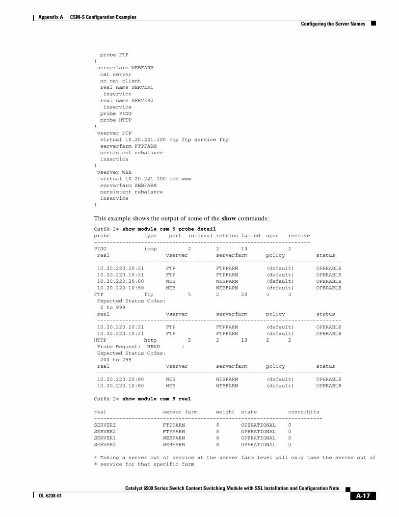
probe FTP! serverfarm WEBFARM nat server no nat client real name SERVER1 inservice real name SERVER2 inservice probe PING probe HTTP! vserver FTP virtual 10.20.221.100 tcp ftp service ftp serverfarm FTPFARM persistent rebalance inservice! vserver WEB virtual 10.20.221.100 tcp www serverfarm WEBFARM persistent rebalance inservice!
This example shows the output of some of the show commands:
Cat6k-2# show module csm 5 probe detail probe type port interval retries failed open receive---------------------------------------------------------------------PING icmp 2 2 10 2 real vserver serverfarm policy status ------------------------------------------------------------------------------ 10.20.220.20:21 FTP FTPFARM (default) OPERABLE 10.20.220.10:21 FTP FTPFARM (default) OPERABLE 10.20.220.20:80 WEB WEBFARM (default) OPERABLE 10.20.220.10:80 WEB WEBFARM (default) OPERABLEFTP ftp 5 2 20 3 3 Expected Status Codes: 0 to 999 real vserver serverfarm policy status ------------------------------------------------------------------------------ 10.20.220.20:21 FTP FTPFARM (default) OPERABLE 10.20.220.10:21 FTP FTPFARM (default) OPERABLEHTTP http 5 2 10 2 2 Probe Request: HEAD / Expected Status Codes: 200 to 299 real vserver serverfarm policy status ------------------------------------------------------------------------------ 10.20.220.20:80 WEB WEBFARM (default) OPERABLE 10.20.220.10:80 WEB WEBFARM (default) OPERABLE
Cat6k-2# show module csm 5 real
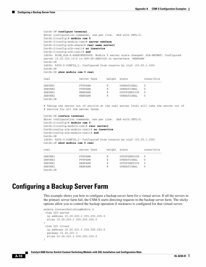
real server farm weight state conns/hits-------------------------------------------------------------------------SERVER1 FTPFARM 8 OPERATIONAL 0 SERVER2 FTPFARM 8 OPERATIONAL 0 SERVER1 WEBFARM 8 OPERATIONAL 0 SERVER2 WEBFARM 8 OPERATIONAL 0
# Taking a server out of service at the server farm level will only take the server out of# service for that specific farm
A-17Catalyst 6500 Series Switch Content Switching Module with SSL Installation and Configuration Note
OL-6238-01
Appendix A CSM-S Configuration ExamplesConfiguring a Backup Server Farm
Cat6k-2# configure terminalEnter configuration commands, one per line. End with CNTL/Z.Cat6k-2(config)# module csm 5Cat6k-2(config-module-csm)# server webfarmCat6k-2(config-slb-sfarm)# real name server1Cat6k-2(config-slb-real)# no inserviceCat6k-2(config-slb-real)# end1d20h: %CSM_SLB-6-RSERVERSTATE: Module 5 server state changed: SLB-NETMGT: Configured server 10.20.220.10:0 to OUT-OF-SERVICE in serverfarm 'WEBFARM'Cat6k-2#1d20h: %SYS-5-CONFIG_I: Configured from console by vty0 (10.20.1.100)Cat6k-2#Cat6k-2# show module csm 5 real
real server farm weight state conns/hits-------------------------------------------------------------------------SERVER1 FTPFARM 8 OPERATIONAL 0 SERVER2 FTPFARM 8 OPERATIONAL 0 SERVER1 WEBFARM 8 OUTOFSERVICE 0 SERVER2 WEBFARM 8 OPERATIONAL 0 Cat6k-2#
# Taking the server out of service at the real server level will take the server out of# service for all the server farms
Cat6k-2# confure terminalEnter configuration commands, one per line. End with CNTL/Z.Cat6k-2(config)# module csm 5Cat6k-2(config-module-csm)# real server1Cat6k(config-slb-module-real)# no inserviceCat6k(config-slb-module-real)# endCat6k-2#1d20h: %SYS-5-CONFIG_I: Configured from console by vty0 (10.20.1.100)Cat6k-2# show module csm 5 real
real server farm weight state conns/hits-------------------------------------------------------------------------SERVER1 FTPFARM 8 OUTOFSERVICE 0 SERVER2 FTPFARM 8 OPERATIONAL 0 SERVER1 WEBFARM 8 OUTOFSERVICE 0 SERVER2 WEBFARM 8 OPERATIONAL 0 Cat6k-2#
Configuring a Backup Server FarmThis example shows you how to configure a backup server farm for a virtual server. If all the servers in the primary server farm fail, the CSM-S starts directing requests to the backup server farm. The sticky options allow you to control the backup operation if stickiness is configured for that virtual server.
module ContentSwitchingModule 5 vlan 220 server ip address 10.20.220.2 255.255.255.0 alias 10.20.220.1 255.255.255.0! vlan 221 client ip address 10.20.221.5 255.255.255.0 gateway 10.20.221.1 alias 10.20.221.2 255.255.255.0!
A-18Catalyst 6500 Series Switch Content Switching Module with SSL Installation and Configuration Note
OL-6238-01
Appendix A CSM-S Configuration ExamplesConfiguring a Backup Server Farm
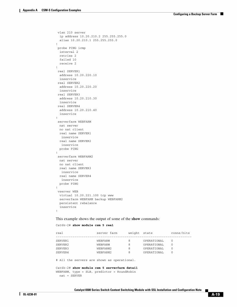
vlan 210 server ip address 10.20.210.2 255.255.255.0 alias 10.20.210.1 255.255.255.0! probe PING icmp interval 2 retries 2 failed 10 receive 2 ! real SERVER1 address 10.20.220.10 inservice real SERVER2 address 10.20.220.20 inservice real SERVER3 address 10.20.210.30 inservice real SERVER4 address 10.20.210.40 inservice! serverfarm WEBFARM nat server no nat client real name SERVER1 inservice real name SERVER2 inservice probe PING! serverfarm WEBFARM2 nat server no nat client real name SERVER3 inservice real name SERVER4 inservice probe PING! vserver WEB virtual 10.20.221.100 tcp www serverfarm WEBFARM backup WEBFARM2 persistent rebalance inservice!
This example shows the output of some of the show commands:
Cat6k-2# show module csm 5 real
real server farm weight state conns/hits-------------------------------------------------------------------------SERVER1 WEBFARM 8 OPERATIONAL 0 SERVER2 WEBFARM 8 OPERATIONAL 0 SERVER3 WEBFARM2 8 OPERATIONAL 0 SERVER4 WEBFARM2 8 OPERATIONAL 0
# All the servers are shown as operational.
Cat6k-2# show module csm 5 serverfarm detailWEBFARM, type = SLB, predictor = RoundRobin nat = SERVER
A-19Catalyst 6500 Series Switch Content Switching Module with SSL Installation and Configuration Note
OL-6238-01
Appendix A CSM-S Configuration ExamplesConfiguring a Backup Server Farm
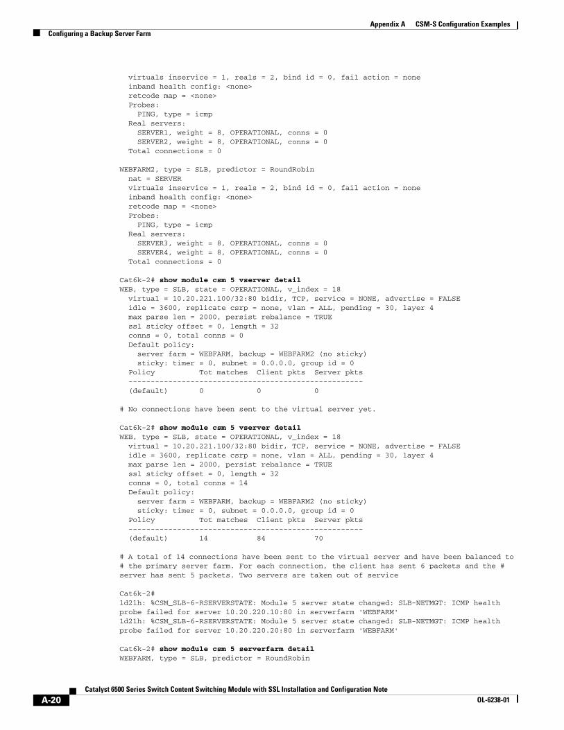
virtuals inservice = 1, reals = 2, bind id = 0, fail action = none inband health config: <none> retcode map = <none> Probes: PING, type = icmp Real servers: SERVER1, weight = 8, OPERATIONAL, conns = 0 SERVER2, weight = 8, OPERATIONAL, conns = 0 Total connections = 0
WEBFARM2, type = SLB, predictor = RoundRobin nat = SERVER virtuals inservice = 1, reals = 2, bind id = 0, fail action = none inband health config: <none> retcode map = <none> Probes: PING, type = icmp Real servers: SERVER3, weight = 8, OPERATIONAL, conns = 0 SERVER4, weight = 8, OPERATIONAL, conns = 0 Total connections = 0
Cat6k-2# show module csm 5 vserver detail WEB, type = SLB, state = OPERATIONAL, v_index = 18 virtual = 10.20.221.100/32:80 bidir, TCP, service = NONE, advertise = FALSE idle = 3600, replicate csrp = none, vlan = ALL, pending = 30, layer 4 max parse len = 2000, persist rebalance = TRUE ssl sticky offset = 0, length = 32 conns = 0, total conns = 0 Default policy: server farm = WEBFARM, backup = WEBFARM2 (no sticky) sticky: timer = 0, subnet = 0.0.0.0, group id = 0 Policy Tot matches Client pkts Server pkts ----------------------------------------------------- (default) 0 0 0
# No connections have been sent to the virtual server yet.
Cat6k-2# show module csm 5 vserver detailWEB, type = SLB, state = OPERATIONAL, v_index = 18 virtual = 10.20.221.100/32:80 bidir, TCP, service = NONE, advertise = FALSE idle = 3600, replicate csrp = none, vlan = ALL, pending = 30, layer 4 max parse len = 2000, persist rebalance = TRUE ssl sticky offset = 0, length = 32 conns = 0, total conns = 14 Default policy: server farm = WEBFARM, backup = WEBFARM2 (no sticky) sticky: timer = 0, subnet = 0.0.0.0, group id = 0 Policy Tot matches Client pkts Server pkts ----------------------------------------------------- (default) 14 84 70
# A total of 14 connections have been sent to the virtual server and have been balanced to # the primary server farm. For each connection, the client has sent 6 packets and the # server has sent 5 packets. Two servers are taken out of service
Cat6k-2#1d21h: %CSM_SLB-6-RSERVERSTATE: Module 5 server state changed: SLB-NETMGT: ICMP health probe failed for server 10.20.220.10:80 in serverfarm 'WEBFARM'1d21h: %CSM_SLB-6-RSERVERSTATE: Module 5 server state changed: SLB-NETMGT: ICMP health probe failed for server 10.20.220.20:80 in serverfarm 'WEBFARM'
Cat6k-2# show module csm 5 serverfarm detailWEBFARM, type = SLB, predictor = RoundRobin
A-20Catalyst 6500 Series Switch Content Switching Module with SSL Installation and Configuration Note
OL-6238-01
Appendix A CSM-S Configuration ExamplesConfiguring a Backup Server Farm
nat = SERVER virtuals inservice = 1, reals = 2, bind id = 0, fail action = none inband health config: <none> retcode map = <none> Probes: PING, type = icmp Real servers: SERVER1, weight = 8, PROBE_FAILED, conns = 0 SERVER2, weight = 8, PROBE_FAILED, conns = 0 Total connections = 0
# The two servers have failed the probe but the CSM-S has not yet refreshed the ARP table# for them, so the servers are not yet shown in the failed state
WEBFARM2, type = SLB, predictor = RoundRobin nat = SERVER virtuals inservice = 1, reals = 2, bind id = 0, fail action = none inband health config: <none> retcode map = <none> Probes: PING, type = icmp Real servers: SERVER3, weight = 8, OPERATIONAL, conns = 0 SERVER4, weight = 8, OPERATIONAL, conns = 0 Total connections = 0
Cat6k-2# show module csm 5 vserver detail WEB, type = SLB, state = OUTOFSERVICE, v_index = 18 virtual = 10.20.221.100/32:80 bidir, TCP, service = NONE, advertise = FALSE idle = 3600, replicate csrp = none, vlan = ALL, pending = 30, layer 4 max parse len = 2000, persist rebalance = TRUE ssl sticky offset = 0, length = 32 conns = 0, total conns = 14 Default policy: server farm = WEBFARM, backup = WEBFARM2 (no sticky) sticky: timer = 0, subnet = 0.0.0.0, group id = 0 Policy Tot matches Client pkts Server pkts ----------------------------------------------------- (default) 14 83 70
# The virtual server is displayed as out of service, even if it is configured with a# backup server farm, which is healthy. This behaviour is useful if the backup server farm# is configured as an HTTP redirect server farm to a different site and you are using some# DNS-based GSLB method, where some connections are still being directed to the failed# virtual server.
# If you want the CSM-S to consider the virtual server healthy and operational if the backup# server farm is healthy, you just need to change an environmental variable.
Cat6k-2# show module csm 5 variable
variable value----------------------------------------------------------------ARP_INTERVAL 300ARP_LEARNED_INTERVAL 14400ARP_GRATUITOUS_INTERVAL 15ARP_RATE 10ARP_RETRIES 3ARP_LEARN_MODE 1ARP_REPLY_FOR_NO_INSERVICE_VIP 0ADVERTISE_RHI_FREQ 10AGGREGATE_BACKUP_SF_STATE_TO_VS 0DEST_UNREACHABLE_MASK 0xffff
A-21Catalyst 6500 Series Switch Content Switching Module with SSL Installation and Configuration Note
OL-6238-01
Appendix A CSM-S Configuration ExamplesConfiguring a Backup Server Farm
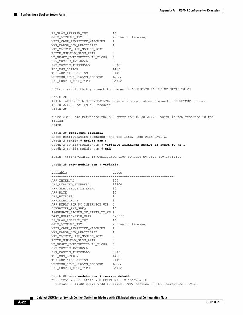
FT_FLOW_REFRESH_INT 15GSLB_LICENSE_KEY (no valid license)HTTP_CASE_SENSITIVE_MATCHING 1MAX_PARSE_LEN_MULTIPLIER 1NAT_CLIENT_HASH_SOURCE_PORT 0ROUTE_UNKNOWN_FLOW_PKTS 0NO_RESET_UNIDIRECTIONAL_FLOWS 0SYN_COOKIE_INTERVAL 3SYN_COOKIE_THRESHOLD 5000TCP_MSS_OPTION 1460TCP_WND_SIZE_OPTION 8192VSERVER_ICMP_ALWAYS_RESPOND falseXML_CONFIG_AUTH_TYPE Basic
# The variable that you want to change is AGGREGATE_BACKUP_SF_STATE_TO_VS
Cat6k-2#1d21h: %CSM_SLB-6-RSERVERSTATE: Module 5 server state changed: SLB-NETMGT: Server 10.20.220.20 failed ARP requestCat6k-2#
# The CSM-S has refreshed the ARP entry for 10.20.220.20 which is now reported in the failedstate.
Cat6k-2# configure terminalEnter configuration commands, one per line. End with CNTL/Z.Cat6k-2(config)# module csm 5Cat6k-2(config-module-csm)# variable AGGREGATE_BACKUP_SF_STATE_TO_VS 1Cat6k-2(config-module-csm)# end
1d21h: %SYS-5-CONFIG_I: Configured from console by vty0 (10.20.1.100)
Cat6k-2# show module csm 5 variable
variable value----------------------------------------------------------------ARP_INTERVAL 300ARP_LEARNED_INTERVAL 14400ARP_GRATUITOUS_INTERVAL 15ARP_RATE 10ARP_RETRIES 3ARP_LEARN_MODE 1ARP_REPLY_FOR_NO_INSERVICE_VIP 0ADVERTISE_RHI_FREQ 10AGGREGATE_BACKUP_SF_STATE_TO_VS 1DEST_UNREACHABLE_MASK 0xffffFT_FLOW_REFRESH_INT 15GSLB_LICENSE_KEY (no valid license)HTTP_CASE_SENSITIVE_MATCHING 1MAX_PARSE_LEN_MULTIPLIER 1NAT_CLIENT_HASH_SOURCE_PORT 0ROUTE_UNKNOWN_FLOW_PKTS 0NO_RESET_UNIDIRECTIONAL_FLOWS 0SYN_COOKIE_INTERVAL 3SYN_COOKIE_THRESHOLD 5000TCP_MSS_OPTION 1460TCP_WND_SIZE_OPTION 8192VSERVER_ICMP_ALWAYS_RESPOND falseXML_CONFIG_AUTH_TYPE Basic
Cat6k-2# show module csm 5 vserver detailWEB, type = SLB, state = OPERATIONAL, v_index = 18 virtual = 10.20.221.100/32:80 bidir, TCP, service = NONE, advertise = FALSE
A-22Catalyst 6500 Series Switch Content Switching Module with SSL Installation and Configuration Note
OL-6238-01
Appendix A CSM-S Configuration ExamplesConfiguring a Backup Server Farm
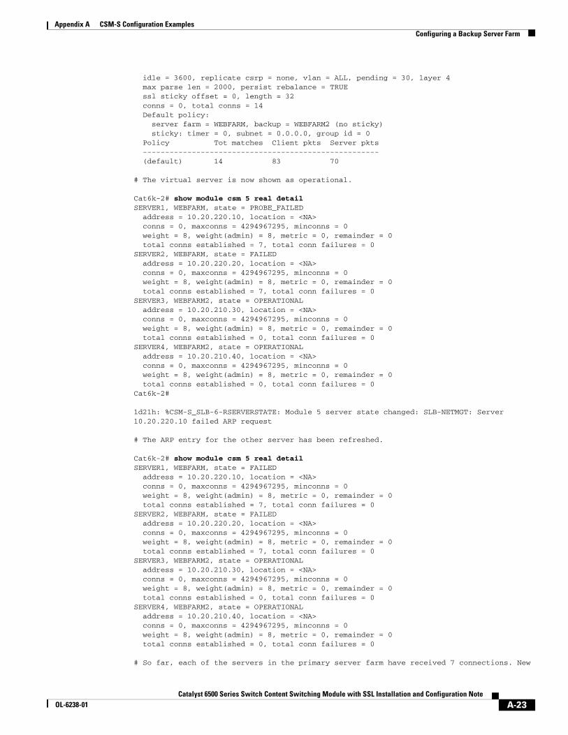
idle = 3600, replicate csrp = none, vlan = ALL, pending = 30, layer 4 max parse len = 2000, persist rebalance = TRUE ssl sticky offset = 0, length = 32 conns = 0, total conns = 14 Default policy: server farm = WEBFARM, backup = WEBFARM2 (no sticky) sticky: timer = 0, subnet = 0.0.0.0, group id = 0 Policy Tot matches Client pkts Server pkts ----------------------------------------------------- (default) 14 83 70
# The virtual server is now shown as operational.
Cat6k-2# show module csm 5 real detail SERVER1, WEBFARM, state = PROBE_FAILED address = 10.20.220.10, location = <NA> conns = 0, maxconns = 4294967295, minconns = 0 weight = 8, weight(admin) = 8, metric = 0, remainder = 0 total conns established = 7, total conn failures = 0SERVER2, WEBFARM, state = FAILED address = 10.20.220.20, location = <NA> conns = 0, maxconns = 4294967295, minconns = 0 weight = 8, weight(admin) = 8, metric = 0, remainder = 0 total conns established = 7, total conn failures = 0SERVER3, WEBFARM2, state = OPERATIONAL address = 10.20.210.30, location = <NA> conns = 0, maxconns = 4294967295, minconns = 0 weight = 8, weight(admin) = 8, metric = 0, remainder = 0 total conns established = 0, total conn failures = 0SERVER4, WEBFARM2, state = OPERATIONAL address = 10.20.210.40, location = <NA> conns = 0, maxconns = 4294967295, minconns = 0 weight = 8, weight(admin) = 8, metric = 0, remainder = 0 total conns established = 0, total conn failures = 0Cat6k-2#
1d21h: %CSM-S_SLB-6-RSERVERSTATE: Module 5 server state changed: SLB-NETMGT: Server 10.20.220.10 failed ARP request
# The ARP entry for the other server has been refreshed.
Cat6k-2# show module csm 5 real detailSERVER1, WEBFARM, state = FAILED address = 10.20.220.10, location = <NA> conns = 0, maxconns = 4294967295, minconns = 0 weight = 8, weight(admin) = 8, metric = 0, remainder = 0 total conns established = 7, total conn failures = 0SERVER2, WEBFARM, state = FAILED address = 10.20.220.20, location = <NA> conns = 0, maxconns = 4294967295, minconns = 0 weight = 8, weight(admin) = 8, metric = 0, remainder = 0 total conns established = 7, total conn failures = 0SERVER3, WEBFARM2, state = OPERATIONAL address = 10.20.210.30, location = <NA> conns = 0, maxconns = 4294967295, minconns = 0 weight = 8, weight(admin) = 8, metric = 0, remainder = 0 total conns established = 0, total conn failures = 0SERVER4, WEBFARM2, state = OPERATIONAL address = 10.20.210.40, location = <NA> conns = 0, maxconns = 4294967295, minconns = 0 weight = 8, weight(admin) = 8, metric = 0, remainder = 0 total conns established = 0, total conn failures = 0
# So far, each of the servers in the primary server farm have received 7 connections. New
A-23Catalyst 6500 Series Switch Content Switching Module with SSL Installation and Configuration Note
OL-6238-01
Appendix A CSM-S Configuration ExamplesConfiguring a Load-Balancing Decision Based on the Source IP Address
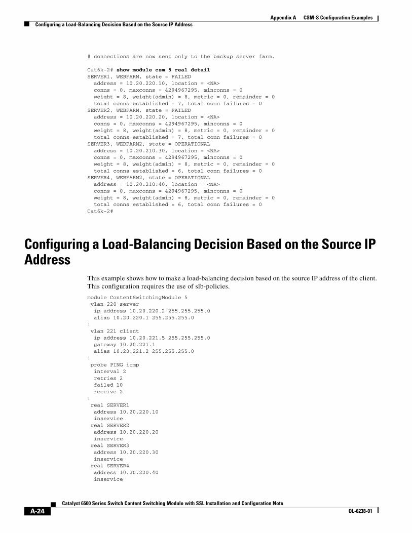
# connections are now sent only to the backup server farm.
Cat6k-2# show module csm 5 real detailSERVER1, WEBFARM, state = FAILED address = 10.20.220.10, location = <NA> conns = 0, maxconns = 4294967295, minconns = 0 weight = 8, weight(admin) = 8, metric = 0, remainder = 0 total conns established = 7, total conn failures = 0SERVER2, WEBFARM, state = FAILED address = 10.20.220.20, location = <NA> conns = 0, maxconns = 4294967295, minconns = 0 weight = 8, weight(admin) = 8, metric = 0, remainder = 0 total conns established = 7, total conn failures = 0SERVER3, WEBFARM2, state = OPERATIONAL address = 10.20.210.30, location = <NA> conns = 0, maxconns = 4294967295, minconns = 0 weight = 8, weight(admin) = 8, metric = 0, remainder = 0 total conns established = 6, total conn failures = 0SERVER4, WEBFARM2, state = OPERATIONAL address = 10.20.210.40, location = <NA> conns = 0, maxconns = 4294967295, minconns = 0 weight = 8, weight(admin) = 8, metric = 0, remainder = 0 total conns established = 6, total conn failures = 0Cat6k-2#
Configuring a Load-Balancing Decision Based on the Source IP Address
This example shows how to make a load-balancing decision based on the source IP address of the client. This configuration requires the use of slb-policies.
module ContentSwitchingModule 5 vlan 220 server ip address 10.20.220.2 255.255.255.0 alias 10.20.220.1 255.255.255.0! vlan 221 client ip address 10.20.221.5 255.255.255.0 gateway 10.20.221.1 alias 10.20.221.2 255.255.255.0! probe PING icmp interval 2 retries 2 failed 10 receive 2 ! real SERVER1 address 10.20.220.10 inservice real SERVER2 address 10.20.220.20 inservice real SERVER3 address 10.20.220.30 inservice real SERVER4 address 10.20.220.40 inservice
A-24Catalyst 6500 Series Switch Content Switching Module with SSL Installation and Configuration Note
OL-6238-01
Appendix A CSM-S Configuration ExamplesConfiguring a Load-Balancing Decision Based on the Source IP Address
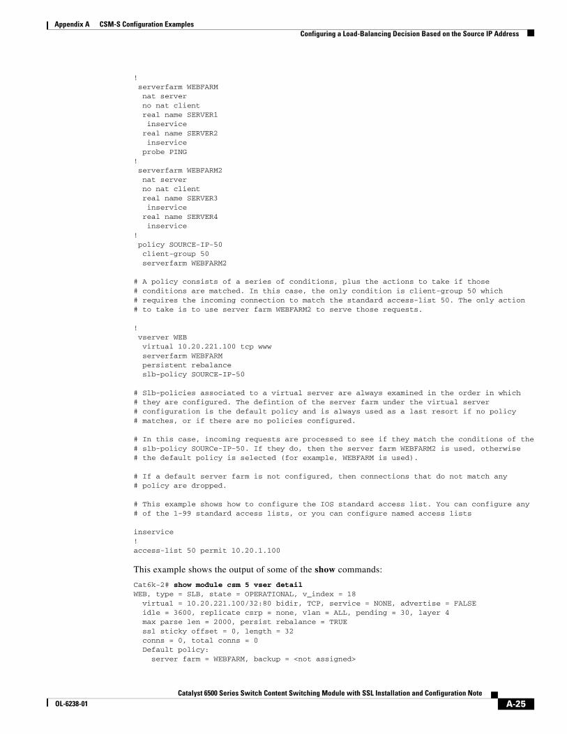
! serverfarm WEBFARM nat server no nat client real name SERVER1 inservice real name SERVER2 inservice probe PING! serverfarm WEBFARM2 nat server no nat client real name SERVER3 inservice real name SERVER4 inservice! policy SOURCE-IP-50 client-group 50 serverfarm WEBFARM2
# A policy consists of a series of conditions, plus the actions to take if those# conditions are matched. In this case, the only condition is client-group 50 which# requires the incoming connection to match the standard access-list 50. The only action# to take is to use server farm WEBFARM2 to serve those requests.
! vserver WEB virtual 10.20.221.100 tcp www serverfarm WEBFARM persistent rebalance slb-policy SOURCE-IP-50
# Slb-policies associated to a virtual server are always examined in the order in which# they are configured. The defintion of the server farm under the virtual server# configuration is the default policy and is always used as a last resort if no policy# matches, or if there are no policies configured.
# In this case, incoming requests are processed to see if they match the conditions of the# slb-policy SOURCe-IP-50. If they do, then the server farm WEBFARM2 is used, otherwise# the default policy is selected (for example, WEBFARM is used).
# If a default server farm is not configured, then connections that do not match any# policy are dropped.
# This example shows how to configure the IOS standard access list. You can configure any# of the 1-99 standard access lists, or you can configure named access lists
inservice!access-list 50 permit 10.20.1.100
This example shows the output of some of the show commands:
Cat6k-2# show module csm 5 vser detailWEB, type = SLB, state = OPERATIONAL, v_index = 18 virtual = 10.20.221.100/32:80 bidir, TCP, service = NONE, advertise = FALSE idle = 3600, replicate csrp = none, vlan = ALL, pending = 30, layer 4 max parse len = 2000, persist rebalance = TRUE ssl sticky offset = 0, length = 32 conns = 0, total conns = 0 Default policy: server farm = WEBFARM, backup = <not assigned>
A-25Catalyst 6500 Series Switch Content Switching Module with SSL Installation and Configuration Note
OL-6238-01
Appendix A CSM-S Configuration ExamplesConfiguring Layer 7 Load Balancing
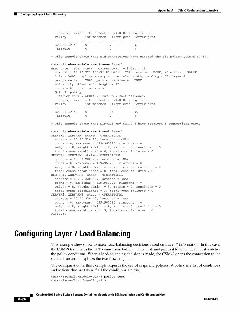
sticky: timer = 0, subnet = 0.0.0.0, group id = 0 Policy Tot matches Client pkts Server pkts ----------------------------------------------------- SOURCE-IP-50 0 0 0 (default) 0 0 0
# This example shows that six connections have matched the slb-policy SOURCE-IP-50.
Cat6k-2# show module csm 5 vser detailWEB, type = SLB, state = OPERATIONAL, v_index = 18 virtual = 10.20.221.100/32:80 bidir, TCP, service = NONE, advertise = FALSE idle = 3600, replicate csrp = none, vlan = ALL, pending = 30, layer 4 max parse len = 2000, persist rebalance = TRUE ssl sticky offset = 0, length = 32 conns = 0, total conns = 6 Default policy: server farm = WEBFARM, backup = <not assigned> sticky: timer = 0, subnet = 0.0.0.0, group id = 0 Policy Tot matches Client pkts Server pkts ----------------------------------------------------- SOURCE-IP-50 6 36 30 (default) 0 0 0
# This example shows that SERVER3 and SERVER4 have received 3 connections each.
Cat6k-2# show module csm 5 real detailSERVER1, WEBFARM, state = OPERATIONAL address = 10.20.220.10, location = <NA> conns = 0, maxconns = 4294967295, minconns = 0 weight = 8, weight(admin) = 8, metric = 0, remainder = 0 total conns established = 0, total conn failures = 0SERVER2, WEBFARM, state = OPERATIONAL address = 10.20.220.20, location = <NA> conns = 0, maxconns = 4294967295, minconns = 0 weight = 8, weight(admin) = 8, metric = 0, remainder = 0 total conns established = 0, total conn failures = 0SERVER3, WEBFARM2, state = OPERATIONAL address = 10.20.220.30, location = <NA> conns = 0, maxconns = 4294967295, minconns = 0 weight = 8, weight(admin) = 8, metric = 0, remainder = 0 total conns established = 3, total conn failures = 0SERVER4, WEBFARM2, state = OPERATIONAL address = 10.20.220.40, location = <NA> conns = 0, maxconns = 4294967295, minconns = 0 weight = 8, weight(admin) = 8, metric = 0, remainder = 0 total conns established = 3, total conn failures = 0Cat6k-2#
Configuring Layer 7 Load BalancingThis example shows how to make load-balancing decisions based on Layer 7 information. In this case, the CSM-S terminates the TCP connection, buffers the request, and parses it to see if the request matches the policy conditions. When a load-balancing decision is made, the CSM-S opens the connection to the selected server and splices the two flows together.
The configuration in this example requires the use of maps and policies. A policy is a list of conditions and actions that are taken if all the conditions are true.
Cat6k-2(config-module-csm)# policy testCat6k-2(config-slb-policy)# ?
A-26Catalyst 6500 Series Switch Content Switching Module with SSL Installation and Configuration Note
OL-6238-01
Appendix A CSM-S Configuration ExamplesConfiguring Layer 7 Load Balancing
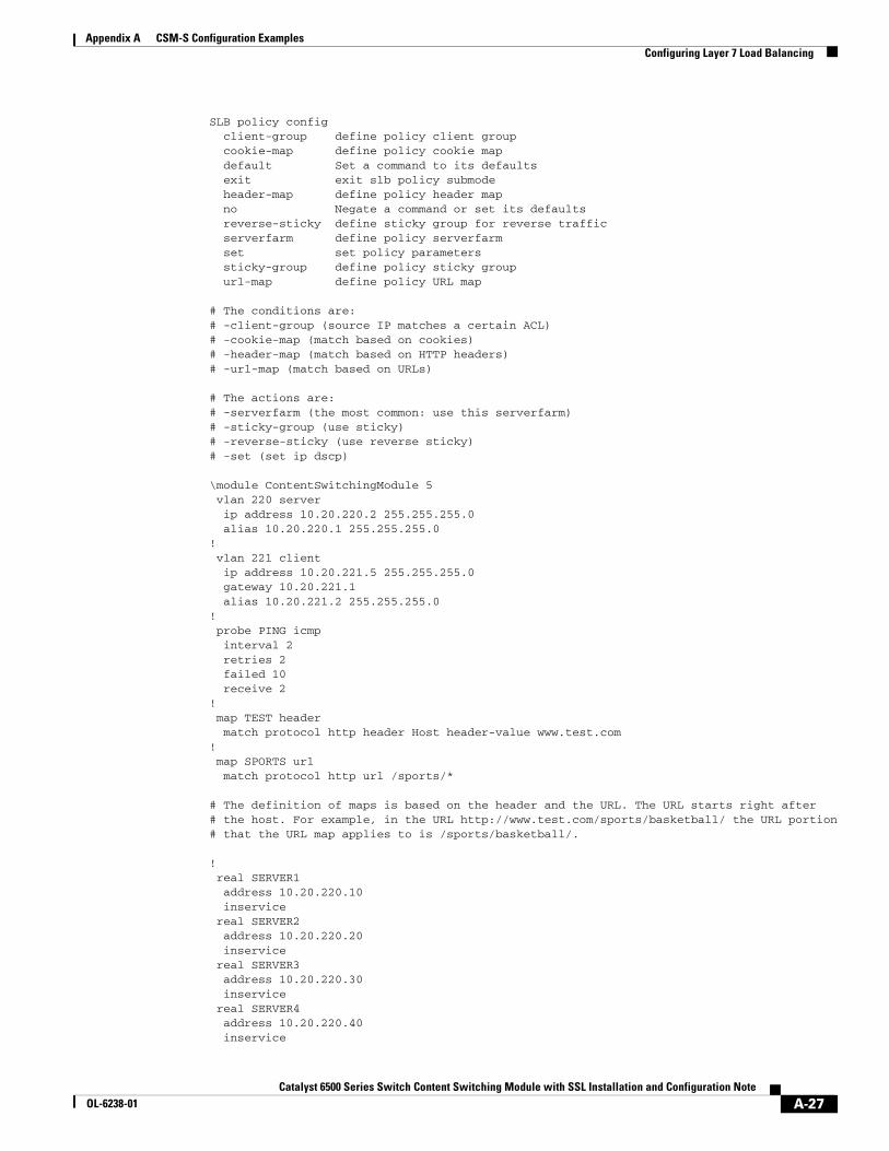
SLB policy config client-group define policy client group cookie-map define policy cookie map default Set a command to its defaults exit exit slb policy submode header-map define policy header map no Negate a command or set its defaults reverse-sticky define sticky group for reverse traffic serverfarm define policy serverfarm set set policy parameters sticky-group define policy sticky group url-map define policy URL map
# The conditions are:# -client-group (source IP matches a certain ACL)# -cookie-map (match based on cookies)# -header-map (match based on HTTP headers)# -url-map (match based on URLs)
# The actions are:# -serverfarm (the most common: use this serverfarm)# -sticky-group (use sticky)# -reverse-sticky (use reverse sticky)# -set (set ip dscp)
\module ContentSwitchingModule 5 vlan 220 server ip address 10.20.220.2 255.255.255.0 alias 10.20.220.1 255.255.255.0! vlan 221 client ip address 10.20.221.5 255.255.255.0 gateway 10.20.221.1 alias 10.20.221.2 255.255.255.0! probe PING icmp interval 2 retries 2 failed 10 receive 2 ! map TEST header match protocol http header Host header-value www.test.com! map SPORTS url match protocol http url /sports/*
# The definition of maps is based on the header and the URL. The URL starts right after# the host. For example, in the URL http://www.test.com/sports/basketball/ the URL portion# that the URL map applies to is /sports/basketball/.
! real SERVER1 address 10.20.220.10 inservice real SERVER2 address 10.20.220.20 inservice real SERVER3 address 10.20.220.30 inservice real SERVER4 address 10.20.220.40 inservice
A-27Catalyst 6500 Series Switch Content Switching Module with SSL Installation and Configuration Note
OL-6238-01
Appendix A CSM-S Configuration ExamplesConfiguring Layer 7 Load Balancing
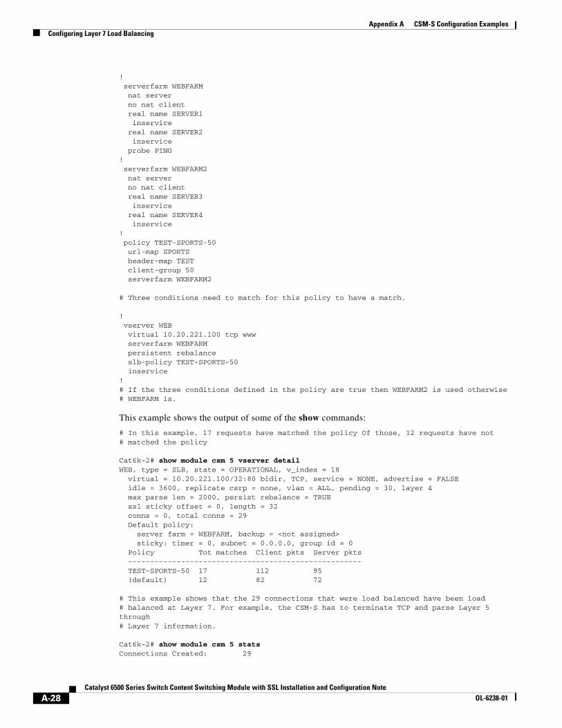
! serverfarm WEBFARM nat server no nat client real name SERVER1 inservice real name SERVER2 inservice probe PING! serverfarm WEBFARM2 nat server no nat client real name SERVER3 inservice real name SERVER4 inservice! policy TEST-SPORTS-50 url-map SPORTS header-map TEST client-group 50 serverfarm WEBFARM2
# Three conditions need to match for this policy to have a match.
! vserver WEB virtual 10.20.221.100 tcp www serverfarm WEBFARM persistent rebalance slb-policy TEST-SPORTS-50 inservice!# If the three conditions defined in the policy are true then WEBFARM2 is used otherwise# WEBFARM is.
This example shows the output of some of the show commands:
# In this example, 17 requests have matched the policy Of those, 12 requests have not# matched the policy
Cat6k-2# show module csm 5 vserver detailWEB, type = SLB, state = OPERATIONAL, v_index = 18 virtual = 10.20.221.100/32:80 bidir, TCP, service = NONE, advertise = FALSE idle = 3600, replicate csrp = none, vlan = ALL, pending = 30, layer 4 max parse len = 2000, persist rebalance = TRUE ssl sticky offset = 0, length = 32 conns = 0, total conns = 29 Default policy: server farm = WEBFARM, backup = <not assigned> sticky: timer = 0, subnet = 0.0.0.0, group id = 0 Policy Tot matches Client pkts Server pkts ----------------------------------------------------- TEST-SPORTS-50 17 112 95 (default) 12 82 72
# This example shows that the 29 connections that were load balanced have been load# balanced at Layer 7. For example, the CSM-S has to terminate TCP and parse Layer 5 through# Layer 7 information.
Cat6k-2# show module csm 5 statsConnections Created: 29
A-28Catalyst 6500 Series Switch Content Switching Module with SSL Installation and Configuration Note
OL-6238-01
Appendix A CSM-S Configuration ExamplesConfiguring HTTP Redirect
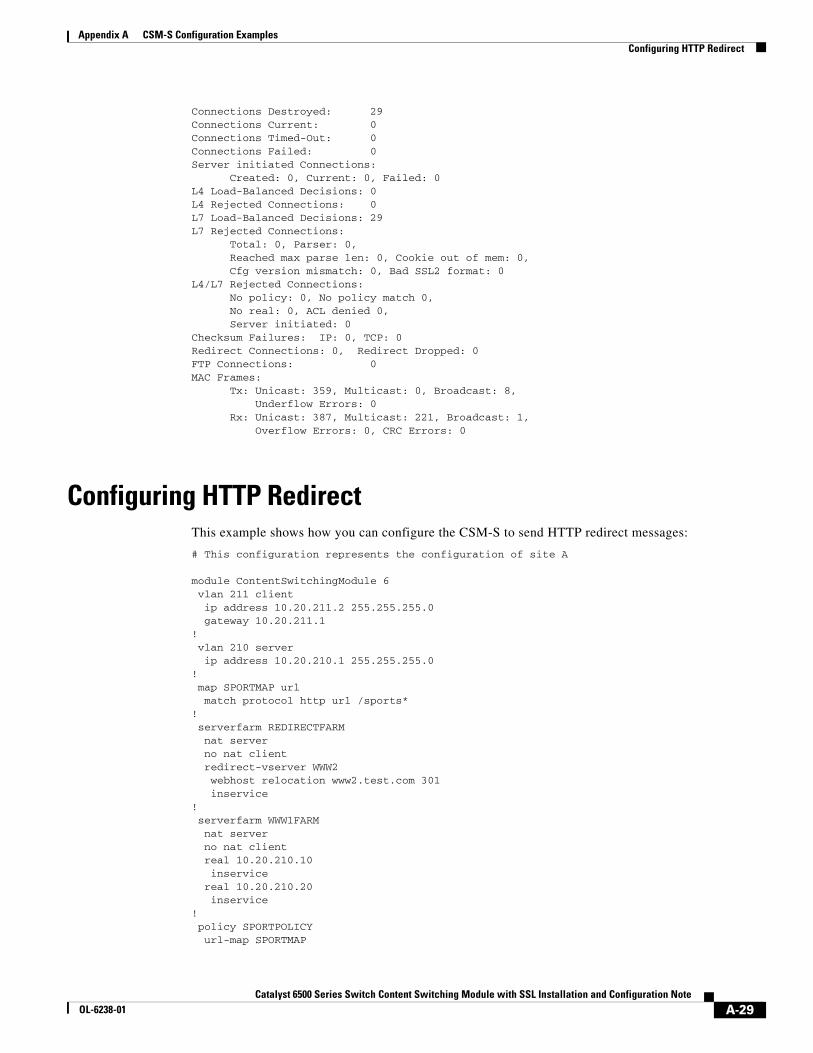
Connections Destroyed: 29Connections Current: 0Connections Timed-Out: 0Connections Failed: 0Server initiated Connections: Created: 0, Current: 0, Failed: 0L4 Load-Balanced Decisions: 0L4 Rejected Connections: 0L7 Load-Balanced Decisions: 29L7 Rejected Connections: Total: 0, Parser: 0, Reached max parse len: 0, Cookie out of mem: 0, Cfg version mismatch: 0, Bad SSL2 format: 0L4/L7 Rejected Connections: No policy: 0, No policy match 0, No real: 0, ACL denied 0, Server initiated: 0Checksum Failures: IP: 0, TCP: 0Redirect Connections: 0, Redirect Dropped: 0FTP Connections: 0MAC Frames: Tx: Unicast: 359, Multicast: 0, Broadcast: 8, Underflow Errors: 0 Rx: Unicast: 387, Multicast: 221, Broadcast: 1, Overflow Errors: 0, CRC Errors: 0
Configuring HTTP RedirectThis example shows how you can configure the CSM-S to send HTTP redirect messages:
# This configuration represents the configuration of site A
module ContentSwitchingModule 6 vlan 211 client ip address 10.20.211.2 255.255.255.0 gateway 10.20.211.1! vlan 210 server ip address 10.20.210.1 255.255.255.0! map SPORTMAP url match protocol http url /sports*! serverfarm REDIRECTFARM nat server no nat client redirect-vserver WWW2 webhost relocation www2.test.com 301 inservice! serverfarm WWW1FARM nat server no nat client real 10.20.210.10 inservice real 10.20.210.20 inservice! policy SPORTPOLICY url-map SPORTMAP
A-29Catalyst 6500 Series Switch Content Switching Module with SSL Installation and Configuration Note
OL-6238-01
Appendix A CSM-S Configuration ExamplesConfiguring HTTP Redirect
serverfarm REDIRECTFARM! vserver WWW1VIP virtual 10.20.211.100 tcp www serverfarm WWW1FARM persistent rebalance slb-policy SPORTPOLICY inservice # This configuration represents the configuration of site B
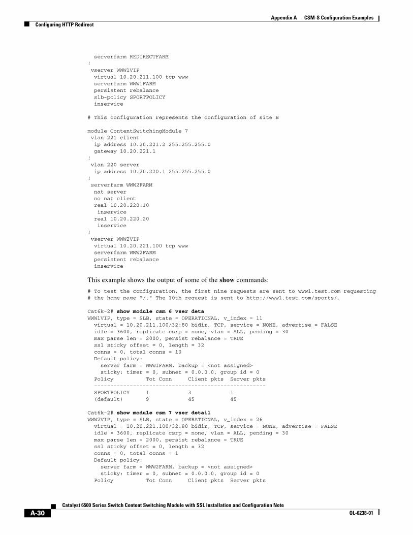
module ContentSwitchingModule 7 vlan 221 client ip address 10.20.221.2 255.255.255.0 gateway 10.20.221.1! vlan 220 server ip address 10.20.220.1 255.255.255.0! serverfarm WWW2FARM nat server no nat client real 10.20.220.10 inservice real 10.20.220.20 inservice! vserver WWW2VIP virtual 10.20.221.100 tcp www serverfarm WWW2FARM persistent rebalance inservice
This example shows the output of some of the show commands:
# To test the configuration, the first nine requests are sent to www1.test.com requesting# the home page “/.” The 10th request is sent to http://www1.test.com/sports/.
Cat6k-2# show module csm 6 vser detaWWW1VIP, type = SLB, state = OPERATIONAL, v_index = 11 virtual = 10.20.211.100/32:80 bidir, TCP, service = NONE, advertise = FALSE idle = 3600, replicate csrp = none, vlan = ALL, pending = 30 max parse len = 2000, persist rebalance = TRUE ssl sticky offset = 0, length = 32 conns = 0, total conns = 10 Default policy: server farm = WWW1FARM, backup = <not assigned> sticky: timer = 0, subnet = 0.0.0.0, group id = 0 Policy Tot Conn Client pkts Server pkts ----------------------------------------------------- SPORTPOLICY 1 3 1 (default) 9 45 45
Cat6k-2# show module csm 7 vser detailWWW2VIP, type = SLB, state = OPERATIONAL, v_index = 26 virtual = 10.20.221.100/32:80 bidir, TCP, service = NONE, advertise = FALSE idle = 3600, replicate csrp = none, vlan = ALL, pending = 30 max parse len = 2000, persist rebalance = TRUE ssl sticky offset = 0, length = 32 conns = 0, total conns = 1 Default policy: server farm = WWW2FARM, backup = <not assigned> sticky: timer = 0, subnet = 0.0.0.0, group id = 0 Policy Tot Conn Client pkts Server pkts
A-30Catalyst 6500 Series Switch Content Switching Module with SSL Installation and Configuration Note
OL-6238-01
Appendix A CSM-S Configuration ExamplesConfiguring HTTP Redirect
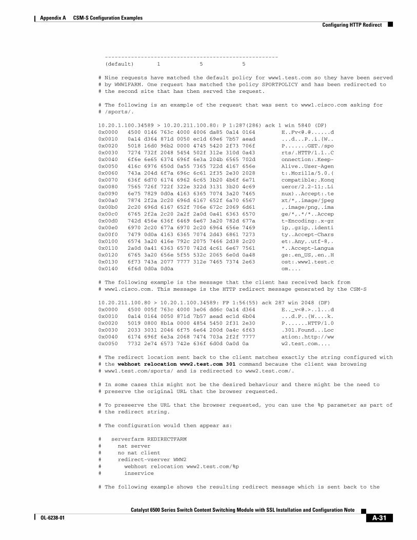
----------------------------------------------------- (default) 1 5 5 # Nine requests have matched the default policy for www1.test.com so they have been served# by WWW1FARM. One request has matched the policy SPORTPOLICY and has been redirected to# the second site that has then served the request.
# The following is an example of the request that was sent to www1.cisco.com asking for# /sports/.
10.20.1.100.34589 > 10.20.211.100.80: P 1:287(286) ack 1 win 5840 (DF)0x0000 4500 0146 763c 4000 4006 da85 0a14 0164 E..Fv<@[email protected] 0a14 d364 871d 0050 ec1d 69e6 7b57 aead ...d...P..i.{W..0x0020 5018 16d0 96b2 0000 4745 5420 2f73 706f P.......GET./spo0x0030 7274 732f 2048 5454 502f 312e 310d 0a43 rts/.HTTP/1.1..C0x0040 6f6e 6e65 6374 696f 6e3a 204b 6565 702d onnection:.Keep-0x0050 416c 6976 650d 0a55 7365 722d 4167 656e Alive..User-Agen0x0060 743a 204d 6f7a 696c 6c61 2f35 2e30 2028 t:.Mozilla/5.0.(0x0070 636f 6d70 6174 6962 6c65 3b20 4b6f 6e71 compatible;.Konq0x0080 7565 726f 722f 322e 322d 3131 3b20 4c69 ueror/2.2-11;.Li0x0090 6e75 7829 0d0a 4163 6365 7074 3a20 7465 nux)..Accept:.te0x00a0 7874 2f2a 2c20 696d 6167 652f 6a70 6567 xt/*,.image/jpeg0x00b0 2c20 696d 6167 652f 706e 672c 2069 6d61 ,.image/png,.ima0x00c0 6765 2f2a 2c20 2a2f 2a0d 0a41 6363 6570 ge/*,.*/*..Accep0x00d0 742d 456e 636f 6469 6e67 3a20 782d 677a t-Encoding:.x-gz0x00e0 6970 2c20 677a 6970 2c20 6964 656e 7469 ip,.gzip,.identi0x00f0 7479 0d0a 4163 6365 7074 2d43 6861 7273 ty..Accept-Chars0x0100 6574 3a20 416e 792c 2075 7466 2d38 2c20 et:.Any,.utf-8,.0x0110 2a0d 0a41 6363 6570 742d 4c61 6e67 7561 *..Accept-Langua0x0120 6765 3a20 656e 5f55 532c 2065 6e0d 0a48 ge:.en_US,.en..H0x0130 6f73 743a 2077 7777 312e 7465 7374 2e63 ost:.www1.test.c0x0140 6f6d 0d0a 0d0a om....
# The following example is the message that the client has received back from# www1.cisco.com. This message is the HTTP redirect message generated by the CSM-S
10.20.211.100.80 > 10.20.1.100.34589: FP 1:56(55) ack 287 win 2048 (DF)0x0000 4500 005f 763c 4000 3e06 dd6c 0a14 d364 E.._v<@.>..l...d0x0010 0a14 0164 0050 871d 7b57 aead ec1d 6b04 ...d.P..{W....k.0x0020 5019 0800 8b1a 0000 4854 5450 2f31 2e30 P.......HTTP/1.00x0030 2033 3031 2046 6f75 6e64 200d 0a4c 6f63 .301.Found...Loc0x0040 6174 696f 6e3a 2068 7474 703a 2f2f 7777 ation:.http://ww0x0050 7732 2e74 6573 742e 636f 6d0d 0a0d 0a w2.test.com....
# The redirect location sent back to the client matches exactly the string configured with# the webhost relocation www2.test.com 301 command because the client was browsing# www1.test.com/sports/ and is redirected to www2.test.com/.
# In some cases this might not be the desired behaviour and there might be the need to# preserve the original URL that the browser requested.
# To preseerve the URL that the browser requested, you can use the %p parameter as part of# the redirect string.
# The configuration would then appear as:
# serverfarm REDIRECTFARM# nat server # no nat client# redirect-vserver WWW2# webhost relocation www2.test.com/%p# inservice
# The following example shows the resulting redirect message which is sent back to the
A-31Catalyst 6500 Series Switch Content Switching Module with SSL Installation and Configuration Note
OL-6238-01
Appendix A CSM-S Configuration ExamplesConfiguring HTTP Redirect
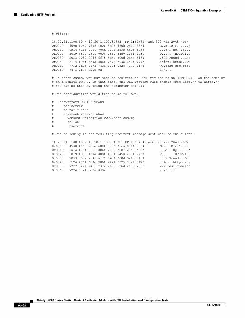
# client:
10.20.211.100.80 > 10.20.1.100.34893: FP 1:64(63) ack 329 win 2048 (DF)0x0000 4500 0067 7d95 4000 3e06 d60b 0a14 d364 E..g}.@.>......d0x0010 0a14 0164 0050 884d 7093 b53b 4e0b e8a8 ...d.P.Mp..;N...0x0020 5019 0800 2800 0000 4854 5450 2f31 2e30 P...(...HTTP/1.00x0030 2033 3032 2046 6f75 6e64 200d 0a4c 6f63 .302.Found...Loc0x0040 6174 696f 6e3a 2068 7474 703a 2f2f 7777 ation:.http://ww0x0050 7732 2e74 6573 742e 636f 6d2f 7370 6f72 w2.test.com/spor0x0060 7473 2f0d 0a0d 0a ts/....
# In other cases, you may need to redirect an HTTP request to an HTTPS VIP, on the same or# on a remote CSM-S. In that case, the URL request must change from http:// to https://# You can do this by using the parameter ssl 443
# The configuration would then be as follows:
# serverfarm REDIRECTFARM# nat server # no nat client# redirect-vserver WWW2# webhost relocation www2.test.com/%p# ssl 443# inservice
# The following is the resulting redirect message sent back to the client.
10.20.211.100.80 > 10.20.1.100.34888: FP 1:65(64) ack 329 win 2048 (DF)0x0000 4500 0068 2cda 4000 3e06 26c6 0a14 d364 E..h,.@.>.&....d0x0010 0a14 0164 0050 8848 7088 b087 21e5 a627 ...d.P.Hp...!..'0x0020 5019 0800 f39e 0000 4854 5450 2f31 2e30 P.......HTTP/1.00x0030 2033 3032 2046 6f75 6e64 200d 0a4c 6f63 .302.Found...Loc0x0040 6174 696f 6e3a 2068 7474 7073 3a2f 2f77 ation:.https://w0x0050 7777 322e 7465 7374 2e63 6f6d 2f73 706f ww2.test.com/spo0x0060 7274 732f 0d0a 0d0a rts/....
A-32Catalyst 6500 Series Switch Content Switching Module with SSL Installation and Configuration Note
OL-6238-01

![[XLS] and Construction... · Web view36 6500 30 3000 9 36 6500 62 4500 42 6500 37 3000 19 17 36 6500 42 6000 19 17 41 6500 36 3000 14 11 31 6500 33 6000 10 8 33 6500 31 3000 10 8](https://img.pdfslide.net/doc/110x75/5aaaff237f8b9a8f498b52b0/xls-and-constructionweb-view36-6500-30-3000-9-36-6500-62-4500-42-6500-37-3000.jpg)