Embed Size (px)
Citation preview
EtherNet/IP AOI Integration Manual 2/4/2016
v1.3
Page 1 of 66
CTS Products EtherNet/IP™ Add-on Instruction RSLogix5000 Integration Manual
CINCINNATI TEST SYSTEMS, INC.
10100 PROGRESS WAY
HARRISON, OHIO 45030
PHONE (513) 367-6699
FAX (513) 367-5426
www.cincinnati-test.com
EtherNet/IP AOI Integration Manual 2/4/2016
v1.3
Page 2 of 66
Software/Firmware Versions
Add-on Instruction Version: 1.2
As tested PLC Code Version: RSLogix5000 v20.01
As tested PLC Firmware Version: 20.18
As tested HMI Software Version: FTView ME v8.1
Minimum Instrument Firmware Version:
C28: v220
I28: v135
Blackbelt: v166
EtherNet/IP AOI Integration Manual 2/4/2016
v1.3
Page 3 of 66
Preface
The following is a program integration process for the CTS supplied Add-on Instruction to be incorporated into new or existing PLC programs. This Add-on Instruction provides EtherNet/IP™ control and communication abilities to the C28, I28 and Blackbelt instruments. These procedures will implement EtherNet/IP integration to system set-ups and must be done in order, otherwise errors may ensue. Please follow the Integration procedures for all CTS systems. There are three sections to this document.
The PLC Integration Procedure
The PLC Integration Procedure instructs the user on how to integrate a new PLC Ethernet Programming into an existing system. It is recommended the PLC Integration Procedure is completed first, before HMI integration.
The HMI Integration Procedure
The HMI Integration Procedure instructs the user on how to integrate a new HMI Ethernet Programming into an existing system.
Validation Procedure
Following the integration procedures, an HMI interface should be functional to test communication between the PLC logic and instrument. We can also test the individual functionality of the instrument(s).
The validation procedure contains the following sections:
Output Validation Input Validation Basic and Detailed Results Results USB Verification Barcode Validation Parent and Sequential Programming User-Configurable Inputs and Outputs
Note: Some features may not be available for all instrumentation.
The Appendix
The Appendix has more information on where to find certain parts needed in the procedures and the part functionality.
EtherNet/IP AOI Integration Manual 2/4/2016
v1.3
Page 4 of 66
PLC Integration Procedure
Note: Do not rename any modules or tags until specified to do so in the order listed below. Doing so may cause communication and syntax errors when integrating the EtherNet/IP driver into a new or existing project.
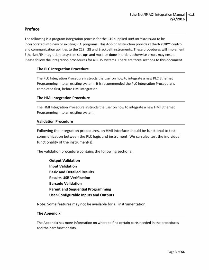
1. Open the Seed RSLogix PLC Project file, “CTS EIP INSTRUMENT SEED.ACD”
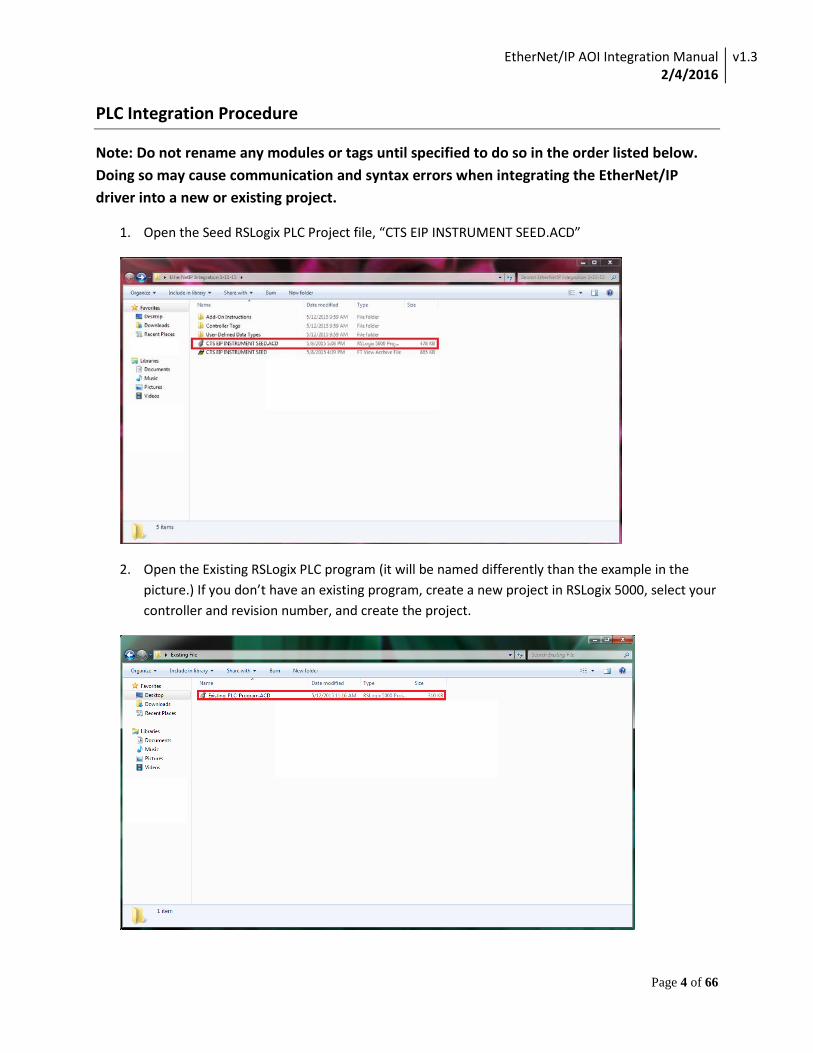
2. Open the Existing RSLogix PLC program (it will be named differently than the example in the picture.) If you don’t have an existing program, create a new project in RSLogix 5000, select your controller and revision number, and create the project.
EtherNet/IP AOI Integration Manual 2/4/2016
v1.3
Page 5 of 66
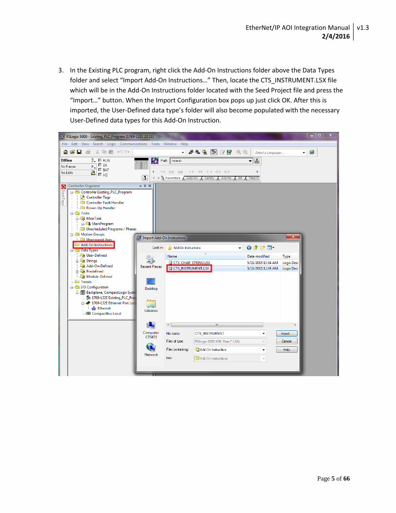
3. In the Existing PLC program, right click the Add-On Instructions folder above the Data Types folder and select “Import Add-On Instructions…” Then, locate the CTS_INSTRUMENT.L5X file which will be in the Add-On Instructions folder located with the Seed Project file and press the “Import…” button. When the Import Configuration box pops up just click OK. After this is imported, the User-Defined data type’s folder will also become populated with the necessary User-Defined data types for this Add-On Instruction.
EtherNet/IP AOI Integration Manual 2/4/2016
v1.3
Page 6 of 66
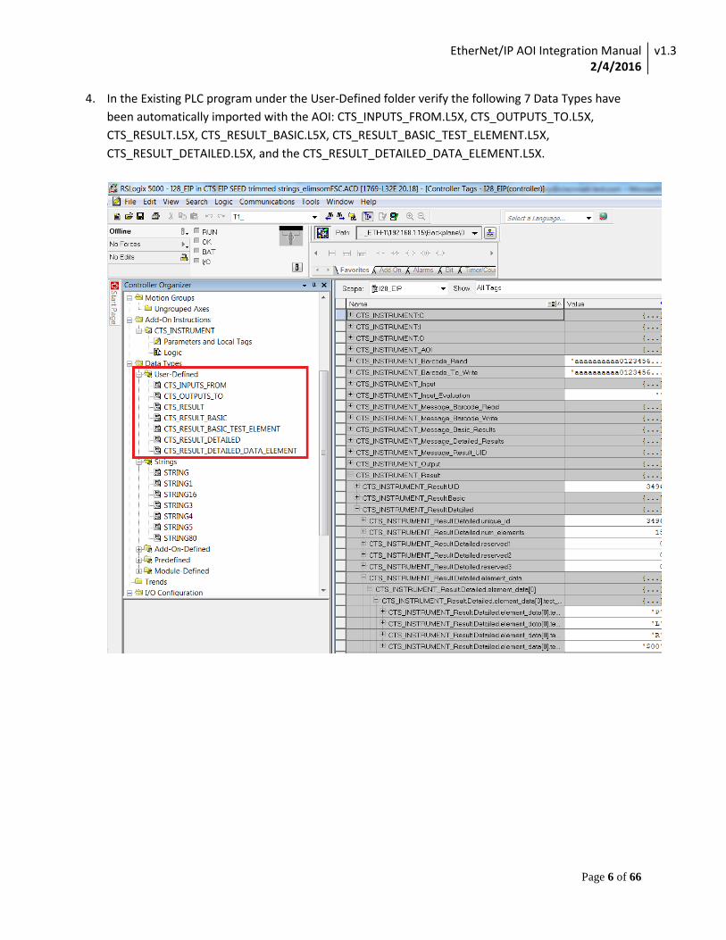
4. In the Existing PLC program under the User-Defined folder verify the following 7 Data Types have been automatically imported with the AOI: CTS_INPUTS_FROM.L5X, CTS_OUTPUTS_TO.L5X, CTS_RESULT.L5X, CTS_RESULT_BASIC.L5X, CTS_RESULT_BASIC_TEST_ELEMENT.L5X, CTS_RESULT_DETAILED.L5X, and the CTS_RESULT_DETAILED_DATA_ELEMENT.L5X.
EtherNet/IP AOI Integration Manual 2/4/2016
v1.3
Page 7 of 66
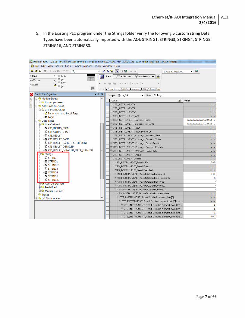
5. In the Existing PLC program under the Strings folder verify the following 6 custom string Data Types have been automatically imported with the AOI: STRING1, STRING3, STRING4, STRING5, STRING16, AND STRING80.
EtherNet/IP AOI Integration Manual 2/4/2016
v1.3
Page 8 of 66
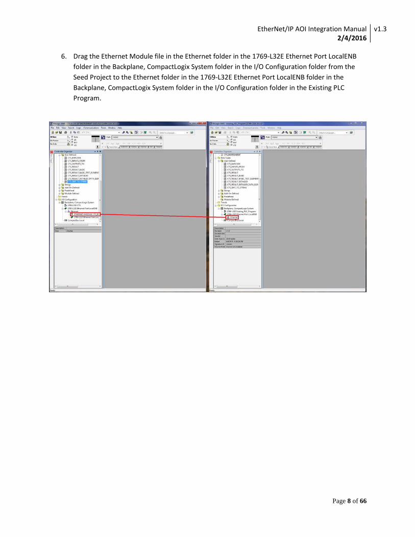
6. Drag the Ethernet Module file in the Ethernet folder in the 1769-L32E Ethernet Port LocalENB folder in the Backplane, CompactLogix System folder in the I/O Configuration folder from the Seed Project to the Ethernet folder in the 1769-L32E Ethernet Port LocalENB folder in the Backplane, CompactLogix System folder in the I/O Configuration folder in the Existing PLC Program.

EtherNet/IP AOI Integration Manual 2/4/2016
v1.3
Page 9 of 66
7. Then the IP address in the Existing PLC Program needs to be changed to the same address as the connected Instrument. (see the ‘Instrument IP Address’ section in the appendix as to where the IP address is located in an instrument) To change the IP address in the Existing PLC Program, double click on the Ethernet Module that was just placed and on the pop-up box locate the IP Address box in the lower left corner and change it to the Instrument’s IP address. Before clicking “OK”, click on the connection tab and proceed to step 8. Note: Changing the IP address of the Ethernet module at any time after the routine containing the AOI is put into the project will require the paths of the messages in the AOI will have to be re-specified manually.
EtherNet/IP AOI Integration Manual 2/4/2016
v1.3
Page 10 of 66
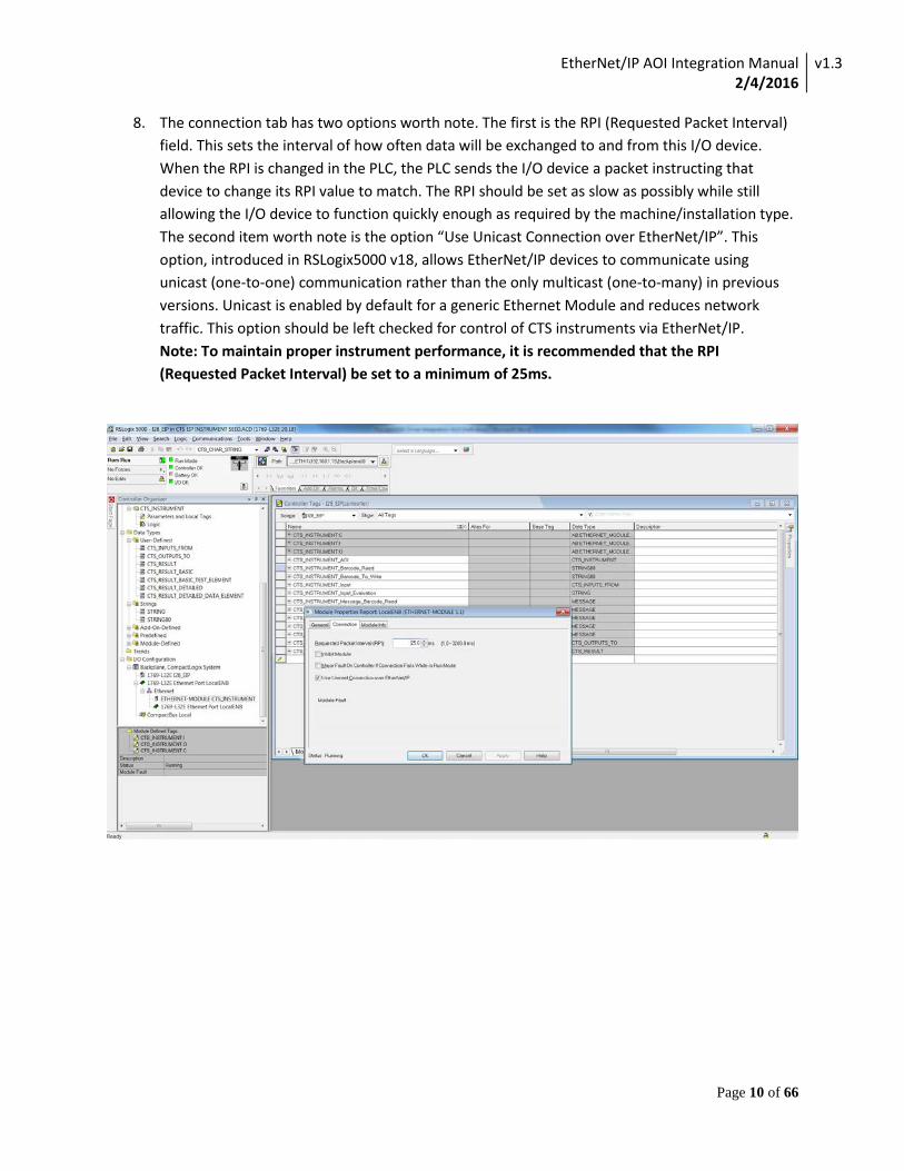
8. The connection tab has two options worth note. The first is the RPI (Requested Packet Interval) field. This sets the interval of how often data will be exchanged to and from this I/O device. When the RPI is changed in the PLC, the PLC sends the I/O device a packet instructing that device to change its RPI value to match. The RPI should be set as slow as possibly while still allowing the I/O device to function quickly enough as required by the machine/installation type. The second item worth note is the option “Use Unicast Connection over EtherNet/IP”. This option, introduced in RSLogix5000 v18, allows EtherNet/IP devices to communicate using unicast (one-to-one) communication rather than the only multicast (one-to-many) in previous versions. Unicast is enabled by default for a generic Ethernet Module and reduces network traffic. This option should be left checked for control of CTS instruments via EtherNet/IP. Note: To maintain proper instrument performance, it is recommended that the RPI (Requested Packet Interval) be set to a minimum of 25ms.
EtherNet/IP AOI Integration Manual 2/4/2016
v1.3
Page 11 of 66
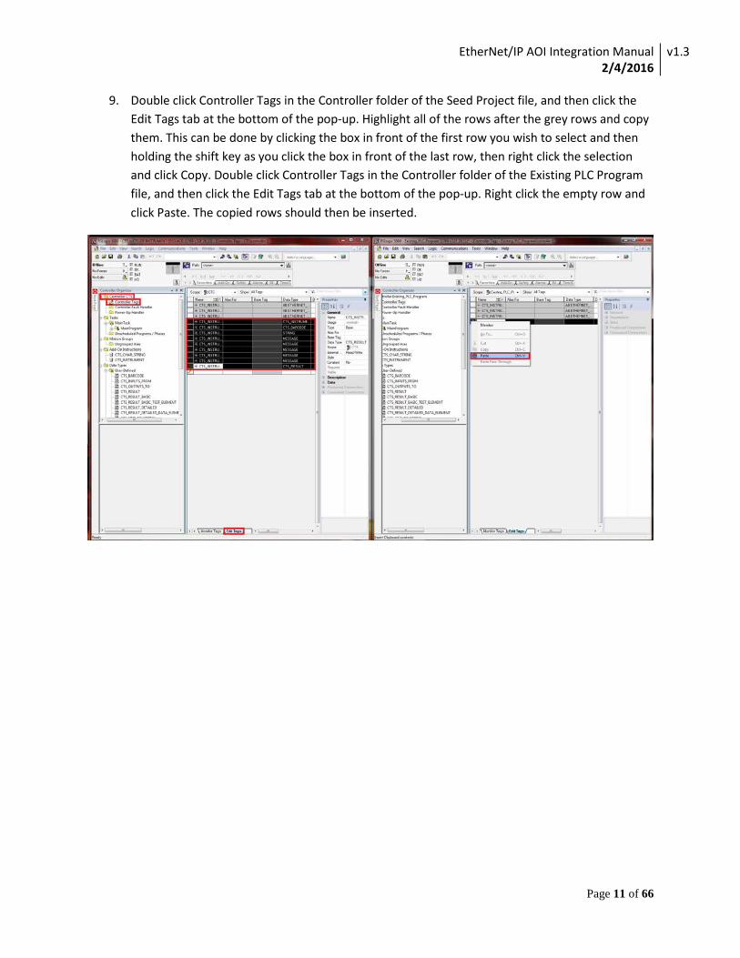
9. Double click Controller Tags in the Controller folder of the Seed Project file, and then click the Edit Tags tab at the bottom of the pop-up. Highlight all of the rows after the grey rows and copy them. This can be done by clicking the box in front of the first row you wish to select and then holding the shift key as you click the box in front of the last row, then right click the selection and click Copy. Double click Controller Tags in the Controller folder of the Existing PLC Program file, and then click the Edit Tags tab at the bottom of the pop-up. Right click the empty row and click Paste. The copied rows should then be inserted.
EtherNet/IP AOI Integration Manual 2/4/2016
v1.3
Page 12 of 66
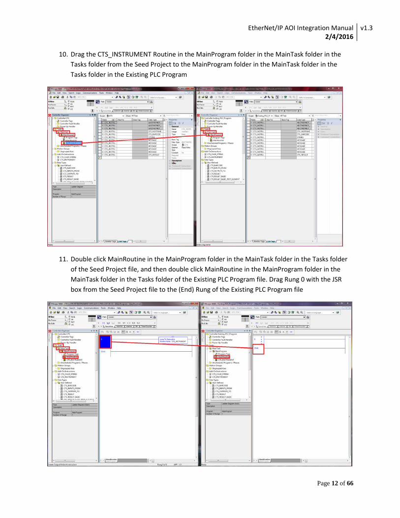
10. Drag the CTS_INSTRUMENT Routine in the MainProgram folder in the MainTask folder in the Tasks folder from the Seed Project to the MainProgram folder in the MainTask folder in the Tasks folder in the Existing PLC Program
11. Double click MainRoutine in the MainProgram folder in the MainTask folder in the Tasks folder of the Seed Project file, and then double click MainRoutine in the MainProgram folder in the MainTask folder in the Tasks folder of the Existing PLC Program file. Drag Rung 0 with the JSR box from the Seed Project file to the (End) Rung of the Existing PLC Program file
EtherNet/IP AOI Integration Manual 2/4/2016
v1.3
Page 13 of 66
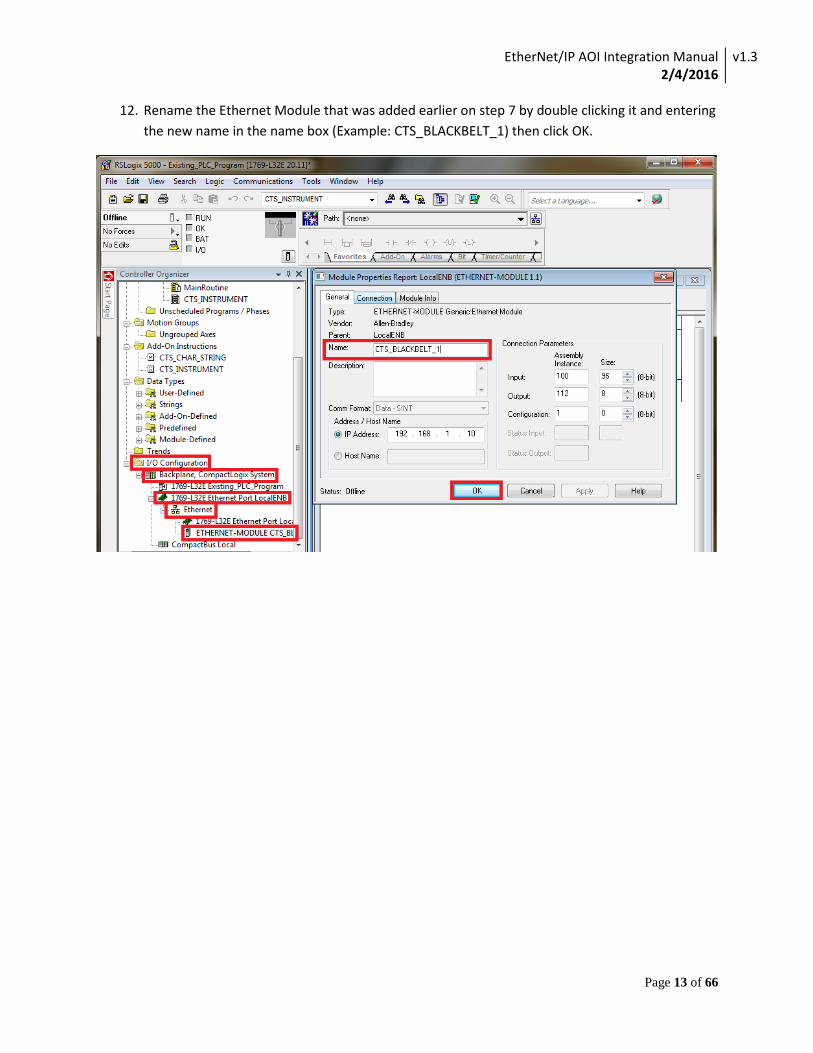
12. Rename the Ethernet Module that was added earlier on step 7 by double clicking it and entering the new name in the name box (Example: CTS_BLACKBELT_1) then click OK.
EtherNet/IP AOI Integration Manual 2/4/2016
v1.3
Page 14 of 66
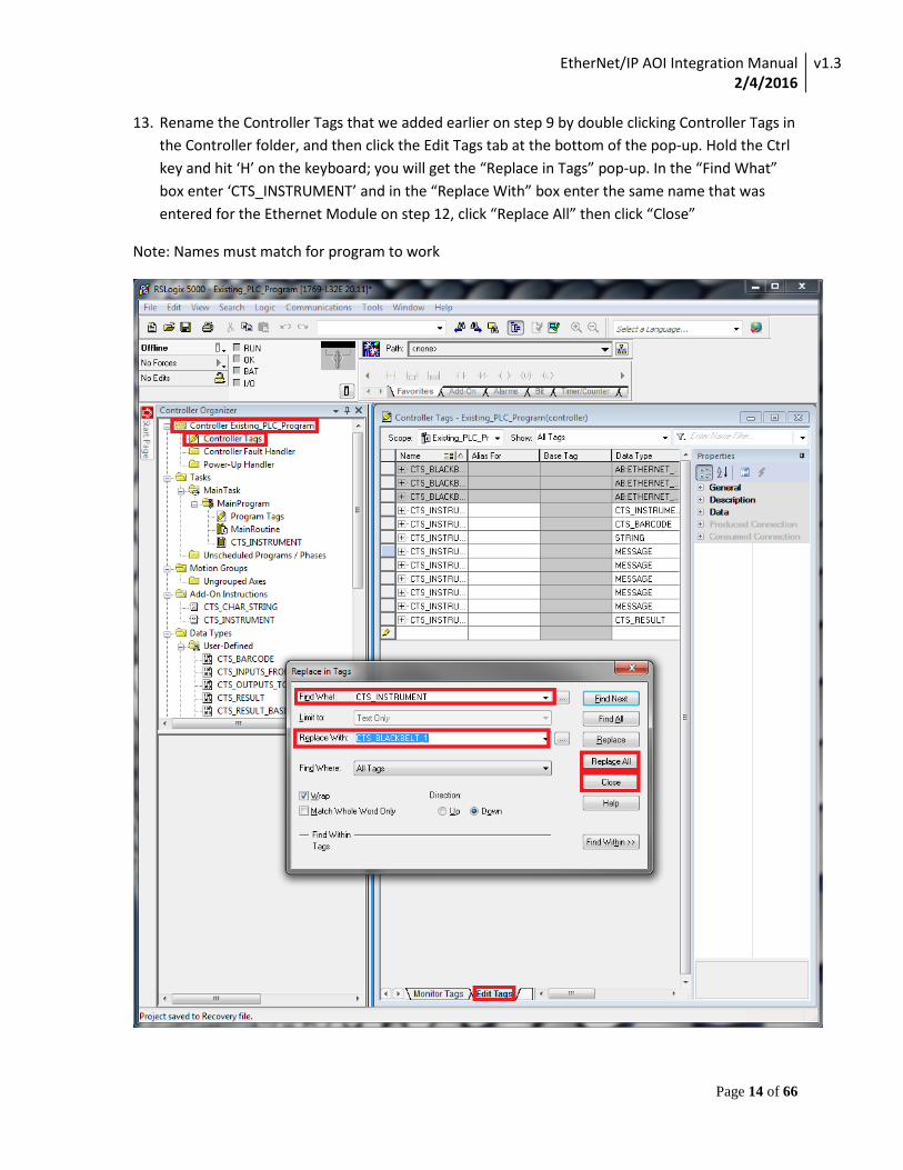
13. Rename the Controller Tags that we added earlier on step 9 by double clicking Controller Tags in the Controller folder, and then click the Edit Tags tab at the bottom of the pop-up. Hold the Ctrl key and hit ‘H’ on the keyboard; you will get the “Replace in Tags” pop-up. In the “Find What” box enter ‘CTS_INSTRUMENT’ and in the “Replace With” box enter the same name that was entered for the Ethernet Module on step 12, click “Replace All” then click “Close”
Note: Names must match for program to work

EtherNet/IP AOI Integration Manual 2/4/2016
v1.3
Page 15 of 66
14. Rename the Routine we added on step 10 by right clicking the routine and clicking Properties, in the Routine Properties pop-up box, change the Name to the same as the Ethernet Module name we used in step 12.
Note: Names must match for program to work
EtherNet/IP AOI Integration Manual 2/4/2016
v1.3
Page 16 of 66
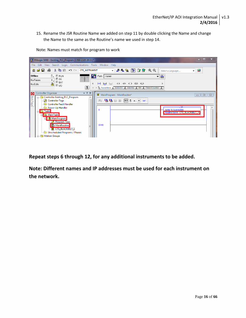
15. Rename the JSR Routine Name we added on step 11 by double clicking the Name and change the Name to the same as the Routine’s name we used in step 14.
Note: Names must match for program to work
Repeat steps 6 through 12, for any additional instruments to be added.
Note: Different names and IP addresses must be used for each instrument on the network.
EtherNet/IP AOI Integration Manual 2/4/2016
v1.3
Page 17 of 66
HMI Integration Procedure
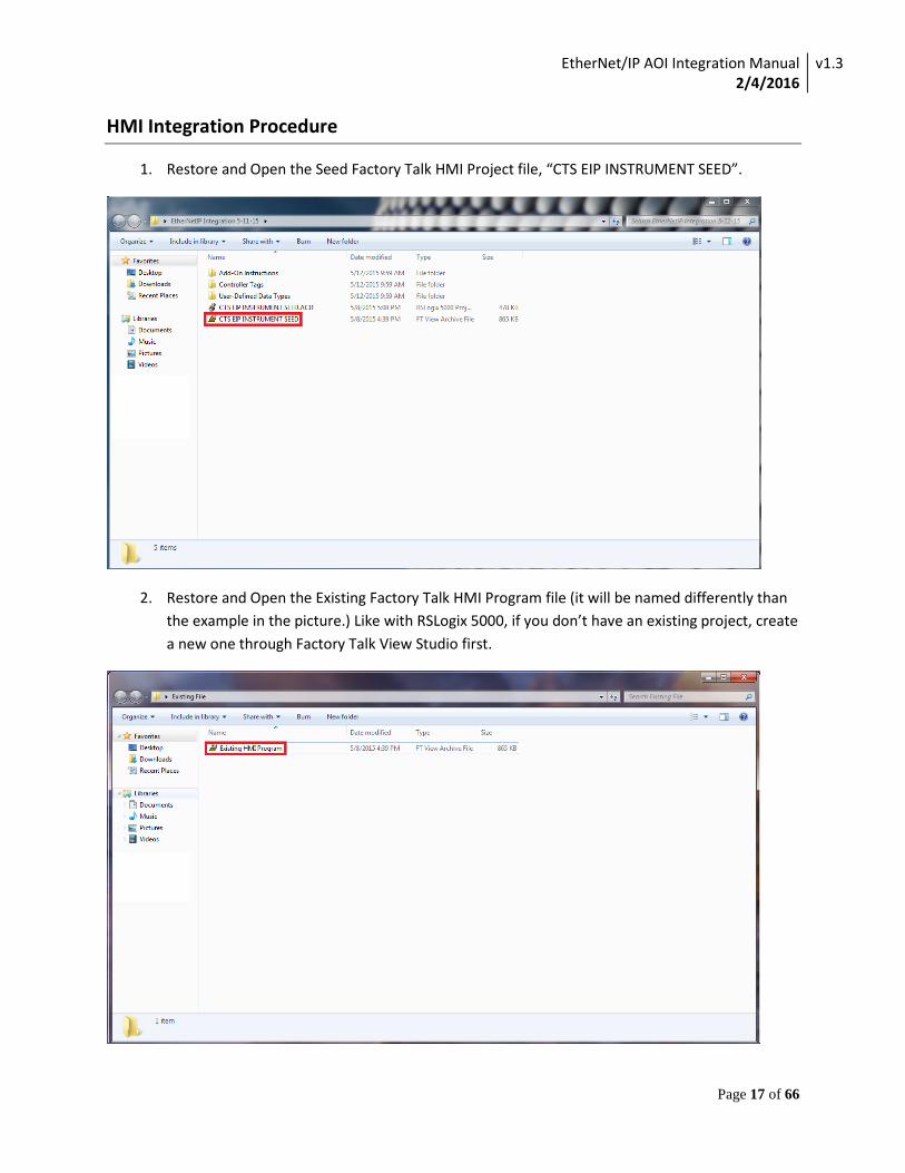
1. Restore and Open the Seed Factory Talk HMI Project file, “CTS EIP INSTRUMENT SEED”.
2. Restore and Open the Existing Factory Talk HMI Program file (it will be named differently than the example in the picture.) Like with RSLogix 5000, if you don’t have an existing project, create a new one through Factory Talk View Studio first.
EtherNet/IP AOI Integration Manual 2/4/2016
v1.3
Page 18 of 66
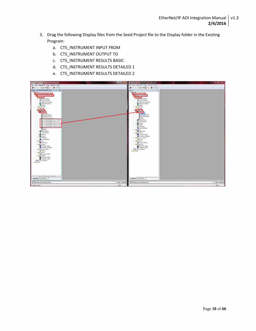
3. Drag the following Display files from the Seed Project file to the Display folder in the Existing Program:
a. CTS_INSTRUMENT INPUT FROM b. CTS_INSTRUMENT OUTPUT TO c. CTS_INSTRUMENT RESULTS BASIC d. CTS_INSTRUMENT RESULTS DETAILED 1 e. CTS_INSTRUMENT RESULTS DETAILED 2
EtherNet/IP AOI Integration Manual 2/4/2016
v1.3
Page 19 of 66
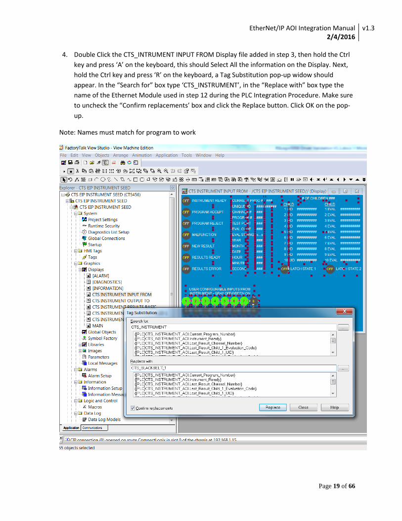
4. Double Click the CTS_INTRUMENT INPUT FROM Display file added in step 3, then hold the Ctrl key and press ‘A’ on the keyboard, this should Select All the information on the Display. Next, hold the Ctrl key and press ‘R’ on the keyboard, a Tag Substitution pop-up widow should appear. In the “Search for” box type ‘CTS_INSTRUMENT’, in the “Replace with” box type the name of the Ethernet Module used in step 12 during the PLC Integration Procedure. Make sure to uncheck the “Confirm replacements’ box and click the Replace button. Click OK on the pop-up.
Note: Names must match for program to work
EtherNet/IP AOI Integration Manual 2/4/2016
v1.3
Page 20 of 66
5. Perform the same steps performed in the previous step to the remaining 4 HMI screens:
CTS_INSTRUMENT OUTPUT TO
CTS_INSTRUMENT RESULTS BASIC
CTS_INSTRUMENT RESULTS DETAILED 1
CTS_INSTRUMENT RESULTS DETAILED 2
EtherNet/IP AOI Integration Manual 2/4/2016
v1.3
Page 21 of 66
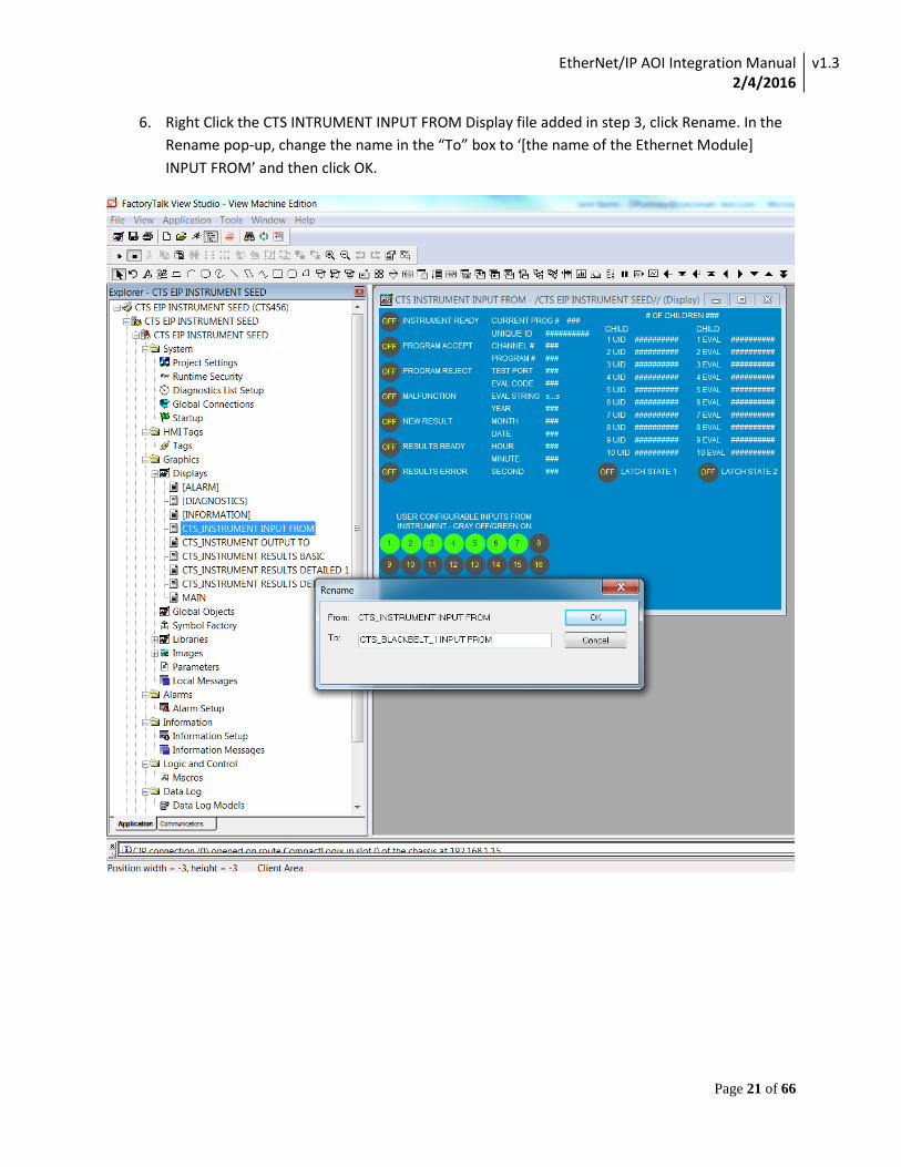
6. Right Click the CTS INTRUMENT INPUT FROM Display file added in step 3, click Rename. In the Rename pop-up, change the name in the “To” box to ‘[the name of the Ethernet Module] INPUT FROM’ and then click OK.
EtherNet/IP AOI Integration Manual 2/4/2016
v1.3
Page 22 of 66
7. Perform the same steps performed in the previous step to the remaining 4 HMI screens:
CTS_INSTRUMENT OUTPUT TO
CTS_INSTRUMENT RESULTS BASIC
CTS_INSTRUMENT RESULTS DETAILED 1
CTS_INSTRUMENT RESULTS DETAILED 2
After completion of this step, if for example your target instrument in the PLC was named “CTS_BLACKBELT_1”, the five screens would show as follows:
CTS_BLACKBELT_1 INPUT FROM
CTS_ BLACKBELT_1 OUTPUT TO
CTS_ BLACKBELT_1 RESULTS BASIC
CTS_ BLACKBELT_1 RESULTS DETAILED 1
CTS_ BLACKBELT_1 RESULTS DETAILED 2
Repeat steps 3 through 7, for any additional instruments to be added.
Note: Different names and IP addresses must be used for each instrument on the network.
EtherNet/IP AOI Integration Manual 2/4/2016
v1.3
Page 23 of 66
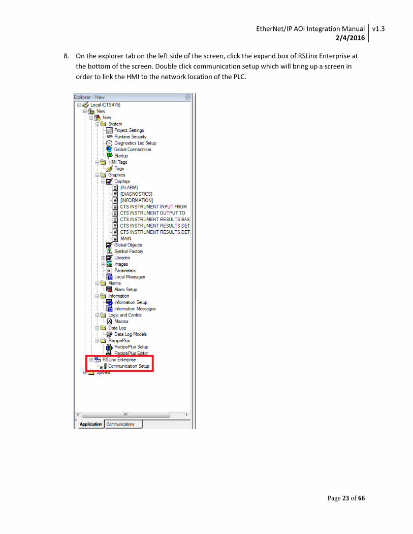
8. On the explorer tab on the left side of the screen, click the expand box of RSLinx Enterprise at the bottom of the screen. Double click communication setup which will bring up a screen in order to link the HMI to the network location of the PLC.
EtherNet/IP AOI Integration Manual 2/4/2016
v1.3
Page 24 of 66
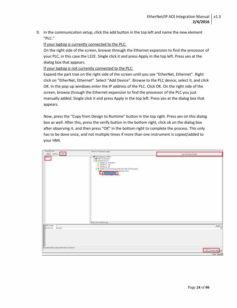
9. In the communication setup, click the add button in the top left and name the new element “PLC.” If your laptop is currently connected to the PLC: On the right side of the screen, browse through the Ethernet expansion to find the processor of your PLC, in this case the L32E. Single click it and press Apply in the top left. Press yes at the dialog box that appears. If your laptop is not currently connected to the PLC: Expand the part tree on the right side of the screen until you see “EtherNet, Ethernet”. Right click on “EtherNet, Ethernet”. Select “Add Device”. Browse to the PLC device, select it, and click OK. In the pop-up windows enter the IP address of the PLC. Click OK. On the right side of the screen, browse through the Ethernet expansion to find the processor of the PLC you just manually added. Single click it and press Apply in the top left. Press yes at the dialog box that appears. Now, press the “Copy from Design to Runtime” button in the top right. Press yes on this dialog box as well. After this, press the verify button in the bottom right, click ok on the dialog box after observing it, and then press “OK” in the bottom right to complete the process. This only has to be done once, and not multiple times if more than one instrument is copied/added to your HMI.
EtherNet/IP AOI Integration Manual 2/4/2016
v1.3
Page 25 of 66
Validation Procedure
After completing the above integration procedures, use the following validation procedures to test out each feature of the AOI.
To complete these procedures the following equipment is necessary:
• CTS Instrument • PLC • HMI Interface
These items should be operational and able to communicate on the same Ethernet network.
Note: Some features may not be available in specific instrumentation. Each section will contain a note if it only applies to a specific product.
EtherNet/IP AOI Integration Manual 2/4/2016
v1.3
Page 26 of 66
Output Validation
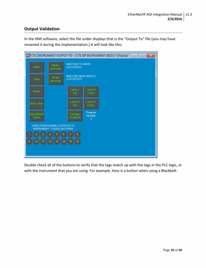
In the HMI software, select the file under displays that is the “Output To” file (you may have renamed it during the implementation.) It will look like this:
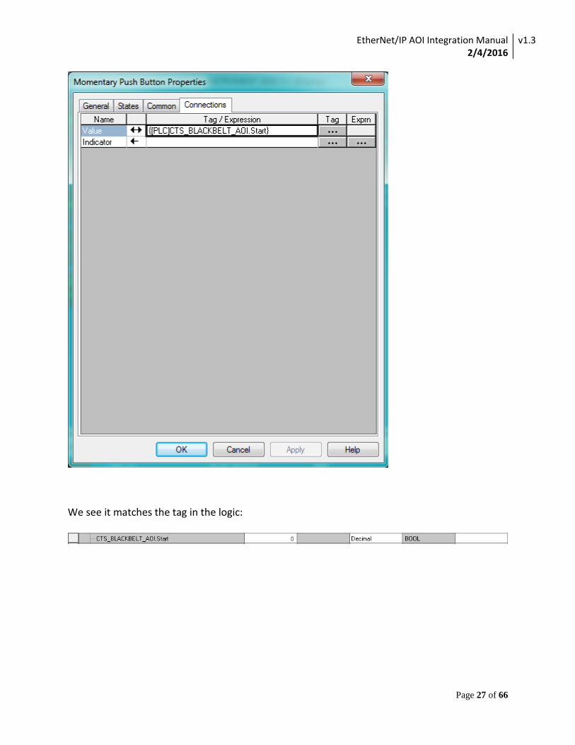
Double check all of the buttons to verify that the tags match up with the tags in the PLC logic, or with the instrument that you are using. For example, here is a button when using a Blackbelt:
EtherNet/IP AOI Integration Manual 2/4/2016
v1.3
Page 27 of 66
We see it matches the tag in the logic:
EtherNet/IP AOI Integration Manual 2/4/2016
v1.3
Page 28 of 66
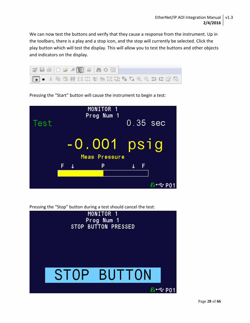
We can now test the buttons and verify that they cause a response from the instrument. Up in the toolbars, there is a play and a stop icon, and the stop will currently be selected. Click the play button which will test the display. This will allow you to test the buttons and other objects and indicators on the display.
Pressing the “Start” button will cause the instrument to begin a test:
Pressing the “Stop” button during a test should cancel the test:
EtherNet/IP AOI Integration Manual 2/4/2016
v1.3
Page 29 of 66
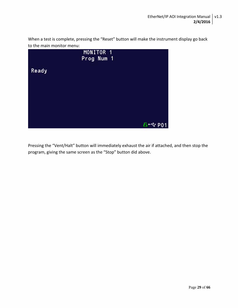
When a test is complete, pressing the “Reset” button will make the instrument display go back to the main monitor menu:
Pressing the “Vent/Halt” button will immediately exhaust the air if attached, and then stop the program, giving the same screen as the “Stop” button did above.
EtherNet/IP AOI Integration Manual 2/4/2016
v1.3
Page 30 of 66
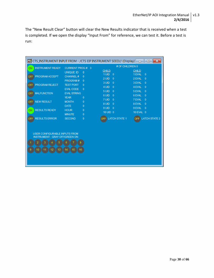
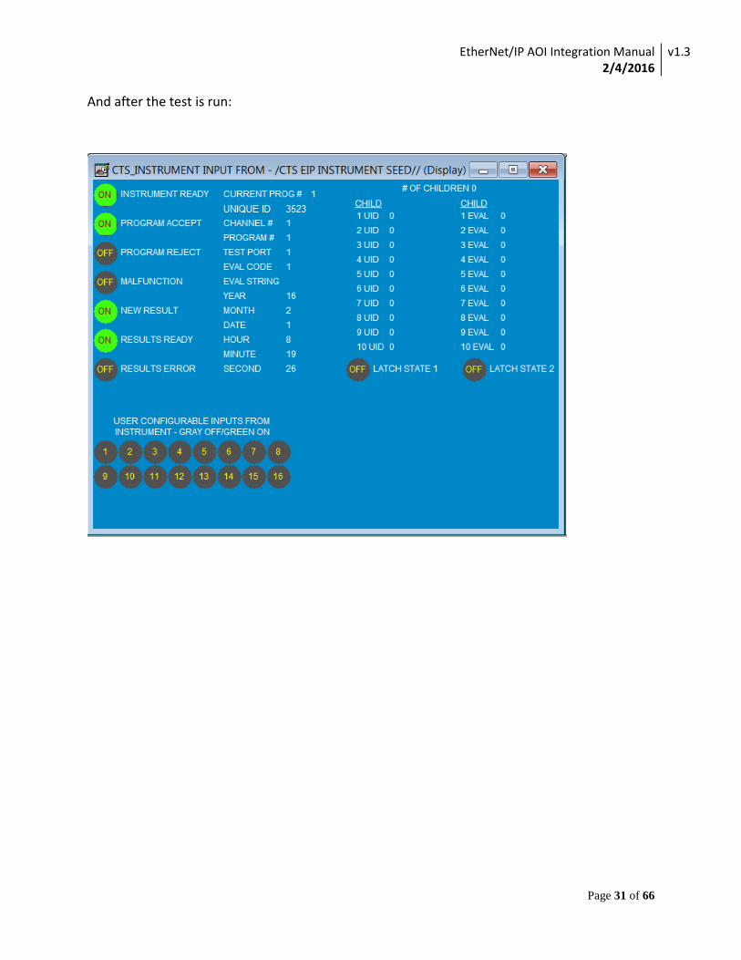
The “New Result Clear” button will clear the New Results indicator that is received when a test is completed. If we open the display “Input From” for reference, we can test it. Before a test is run:
EtherNet/IP AOI Integration Manual 2/4/2016
v1.3
Page 31 of 66
And after the test is run:
EtherNet/IP AOI Integration Manual 2/4/2016
v1.3
Page 32 of 66
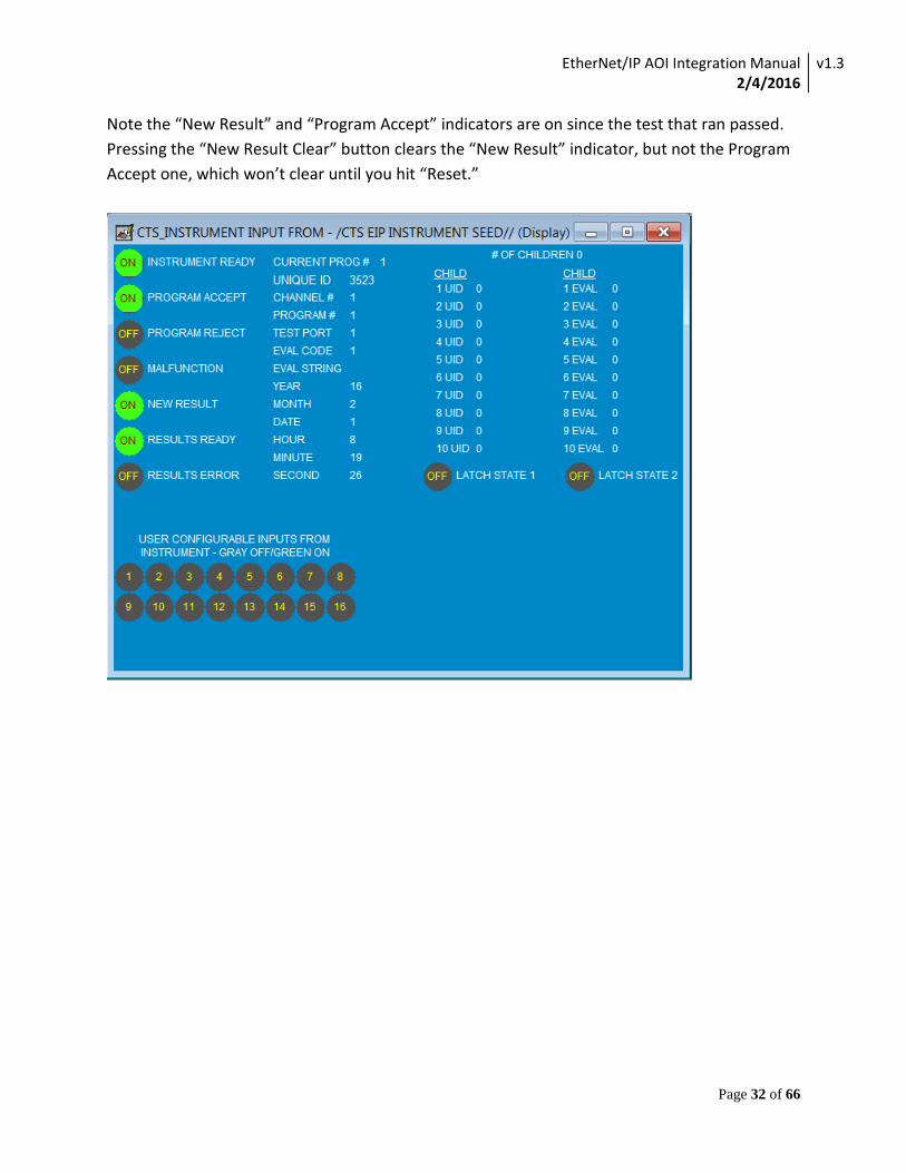
Note the “New Result” and “Program Accept” indicators are on since the test that ran passed. Pressing the “New Result Clear” button clears the “New Result” indicator, but not the Program Accept one, which won’t clear until you hit “Reset.”
EtherNet/IP AOI Integration Manual 2/4/2016
v1.3
Page 33 of 66
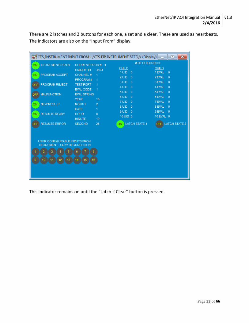
There are 2 latches and 2 buttons for each one, a set and a clear. These are used as heartbeats. The indicators are also on the “Input From” display.
This indicator remains on until the “Latch # Clear” button is pressed.

EtherNet/IP AOI Integration Manual 2/4/2016
v1.3
Page 34 of 66
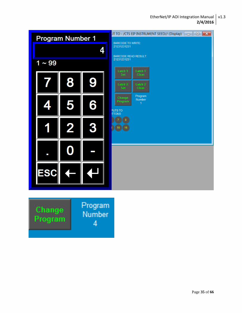
To change the program number, single click the actual text that says “Program Number #”, which will bring up a numerical input to put in a program number.
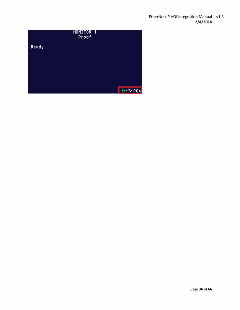
This will queue up the Program Number, to actually send it to the instrument and change it; you have to press the “Change Program” button. So for example if program 4 is entered:
EtherNet/IP AOI Integration Manual 2/4/2016
v1.3
Page 35 of 66
EtherNet/IP AOI Integration Manual 2/4/2016
v1.3
Page 36 of 66
EtherNet/IP AOI Integration Manual 2/4/2016
v1.3
Page 37 of 66
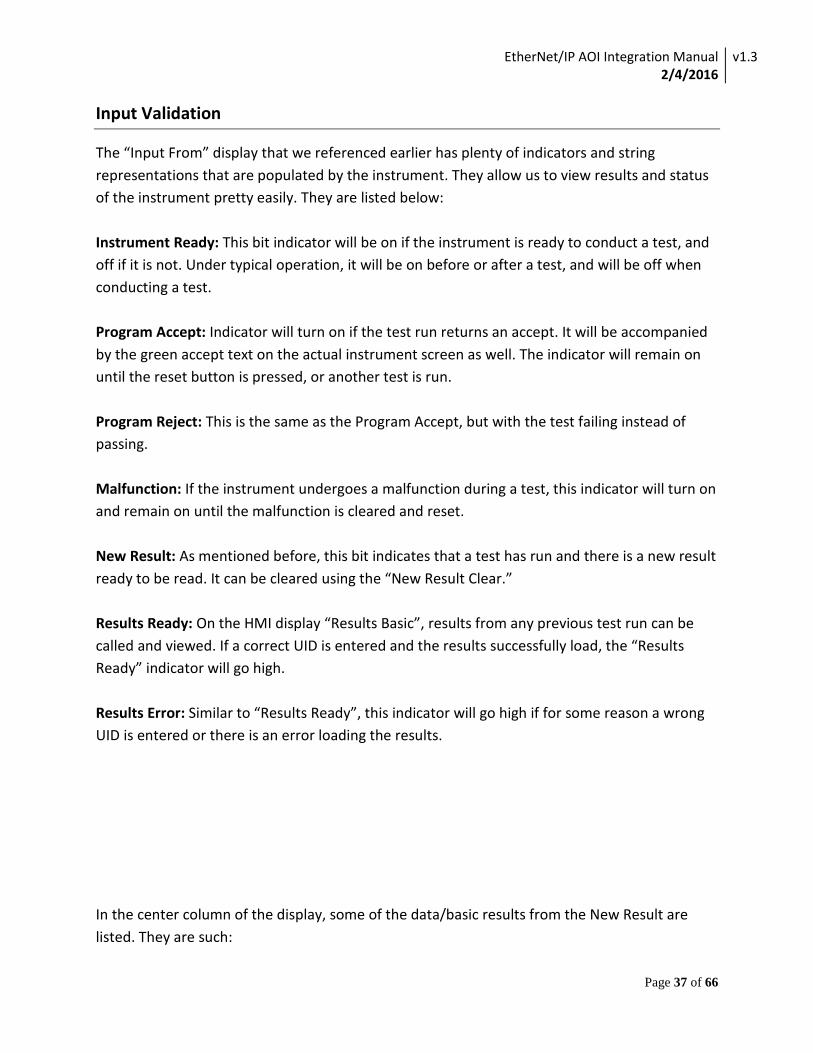
Input Validation
The “Input From” display that we referenced earlier has plenty of indicators and string representations that are populated by the instrument. They allow us to view results and status of the instrument pretty easily. They are listed below: Instrument Ready: This bit indicator will be on if the instrument is ready to conduct a test, and off if it is not. Under typical operation, it will be on before or after a test, and will be off when conducting a test. Program Accept: Indicator will turn on if the test run returns an accept. It will be accompanied by the green accept text on the actual instrument screen as well. The indicator will remain on until the reset button is pressed, or another test is run. Program Reject: This is the same as the Program Accept, but with the test failing instead of passing. Malfunction: If the instrument undergoes a malfunction during a test, this indicator will turn on and remain on until the malfunction is cleared and reset. New Result: As mentioned before, this bit indicates that a test has run and there is a new result ready to be read. It can be cleared using the “New Result Clear.” Results Ready: On the HMI display “Results Basic”, results from any previous test run can be called and viewed. If a correct UID is entered and the results successfully load, the “Results Ready” indicator will go high. Results Error: Similar to “Results Ready”, this indicator will go high if for some reason a wrong UID is entered or there is an error loading the results. In the center column of the display, some of the data/basic results from the New Result are listed. They are such:
EtherNet/IP AOI Integration Manual 2/4/2016
v1.3
Page 38 of 66
Current Prog #1: The current program selected on the instrument. If the program number is changed, all of the results below will be cleared. Unique ID: This is the ID number for the test that has been run. You can use this ID to fetch the results of this test at a later time for reference. Channel #: This is the output channel of the PLC that the test was run on. Program #: This is the program that was run, corresponding to the listed UID. Test Port: The output port at which the test was run. Eval Code: This will give a number code that is a numerical representation of a pass, fail, etc. Eval String: This is the string text version of the result of test. So for example, if the test succeeds, it will be “Accept”, if it fails, “Reject.” Year/Month/Date/Hour/Minute/Second: Shows the date and time at which the test was completed.

EtherNet/IP AOI Integration Manual 2/4/2016
v1.3
Page 39 of 66
Exampled of a completed test that was accepted:
EtherNet/IP AOI Integration Manual 2/4/2016
v1.3
Page 40 of 66
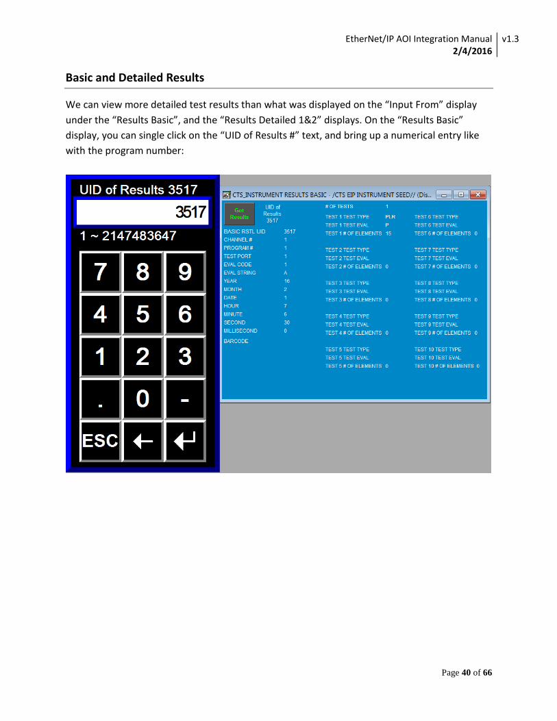
Basic and Detailed Results
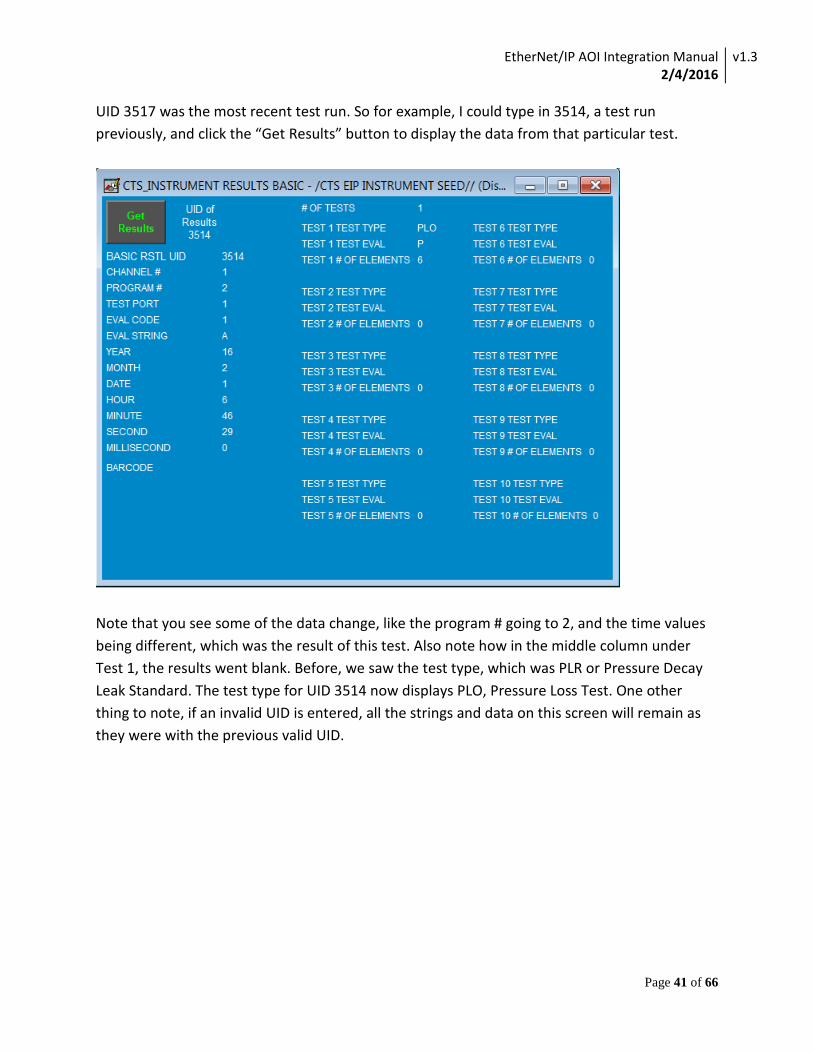
We can view more detailed test results than what was displayed on the “Input From” display under the “Results Basic”, and the “Results Detailed 1&2” displays. On the “Results Basic” display, you can single click on the “UID of Results #” text, and bring up a numerical entry like with the program number:
EtherNet/IP AOI Integration Manual 2/4/2016
v1.3
Page 41 of 66
UID 3517 was the most recent test run. So for example, I could type in 3514, a test run previously, and click the “Get Results” button to display the data from that particular test.
Note that you see some of the data change, like the program # going to 2, and the time values being different, which was the result of this test. Also note how in the middle column under Test 1, the results went blank. Before, we saw the test type, which was PLR or Pressure Decay Leak Standard. The test type for UID 3514 now displays PLO, Pressure Loss Test. One other thing to note, if an invalid UID is entered, all the strings and data on this screen will remain as they were with the previous valid UID.
EtherNet/IP AOI Integration Manual 2/4/2016
v1.3
Page 42 of 66
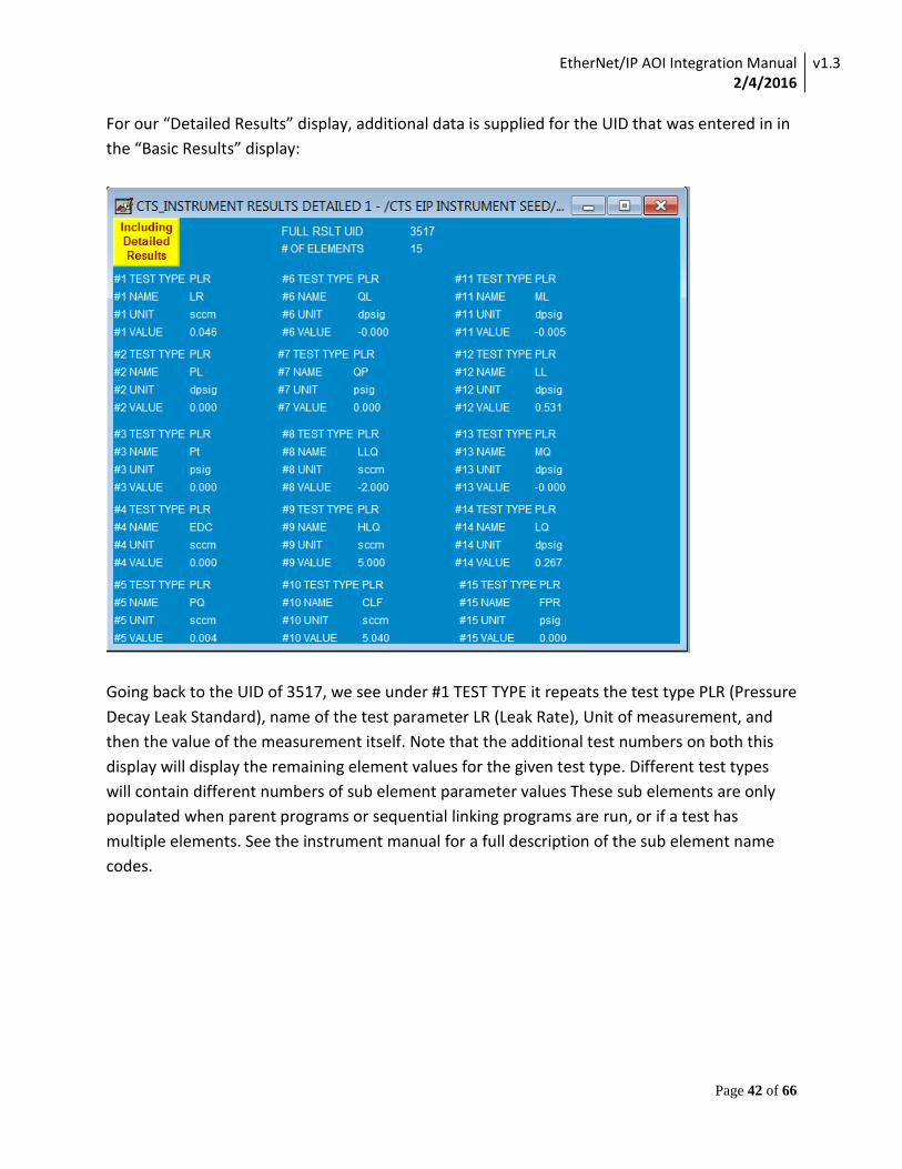
For our “Detailed Results” display, additional data is supplied for the UID that was entered in in the “Basic Results” display:
Going back to the UID of 3517, we see under #1 TEST TYPE it repeats the test type PLR (Pressure Decay Leak Standard), name of the test parameter LR (Leak Rate), Unit of measurement, and then the value of the measurement itself. Note that the additional test numbers on both this display will display the remaining element values for the given test type. Different test types will contain different numbers of sub element parameter values These sub elements are only populated when parent programs or sequential linking programs are run, or if a test has multiple elements. See the instrument manual for a full description of the sub element name codes.

EtherNet/IP AOI Integration Manual 2/4/2016
v1.3
Page 43 of 66
A function not shown before in this document has been added that provides an error indicator for if a result message does not reach the instrument. If there is an issue with message communication when trying to obtain a result the attempt to get results will timeout and an error will be indicated.
Note that the button will be stuck on “Getting Results” for a very short time.
EtherNet/IP AOI Integration Manual 2/4/2016
v1.3
Page 44 of 66
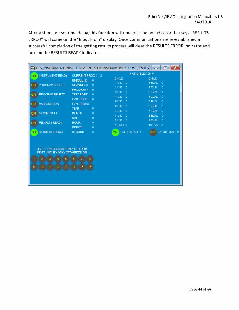
After a short pre-set time delay, this function will time out and an indicator that says “RESULTS ERROR” will come on the “Input From” display. Once communications are re-established a successful completion of the getting results process will clear the RESULTS ERROR indicator and turn on the RESULTS READY indicator.
EtherNet/IP AOI Integration Manual 2/4/2016
v1.3
Page 45 of 66
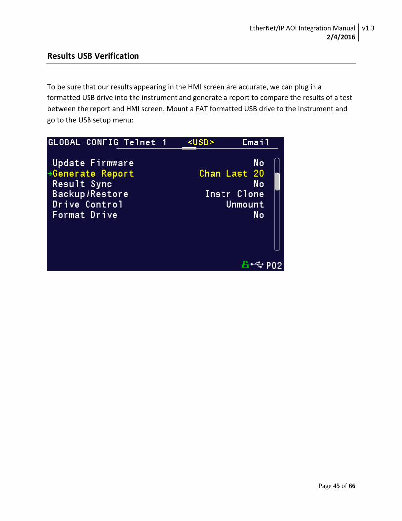
Results USB Verification
To be sure that our results appearing in the HMI screen are accurate, we can plug in a formatted USB drive into the instrument and generate a report to compare the results of a test between the report and HMI screen. Mount a FAT formatted USB drive to the instrument and go to the USB setup menu:
EtherNet/IP AOI Integration Manual 2/4/2016
v1.3
Page 46 of 66
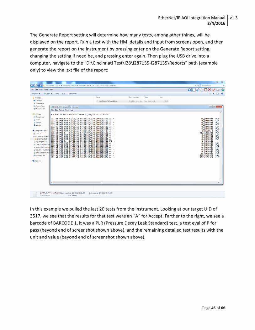
The Generate Report setting will determine how many tests, among other things, will be displayed on the report. Run a test with the HMI details and Input from screens open, and then generate the report on the instrument by pressing enter on the Generate Report setting, changing the setting if need be, and pressing enter again. Then plug the USB drive into a computer, navigate to the “D:\Cincinnati Test\I28\I287135-I287135\Reports” path (example only) to view the .txt file of the report:
In this example we pulled the last 20 tests from the instrument. Looking at our target UID of 3517, we see that the results for that test were an “A” for Accept. Farther to the right, we see a barcode of BARCODE 1, it was a PLR (Pressure Decay Leak Standard) test, a test eval of P for pass (beyond end of screenshot shown above), and the remaining detailed test results with the unit and value (beyond end of screenshot shown above).

EtherNet/IP AOI Integration Manual 2/4/2016
v1.3
Page 47 of 66
Looking at our HMI screens for the same test:

EtherNet/IP AOI Integration Manual 2/4/2016
v1.3
Page 48 of 66
We observe that all the results match one another on the HMI and the USB report.

EtherNet/IP AOI Integration Manual 2/4/2016
v1.3
Page 49 of 66
Barcode Validation
Note: Only the I28 and the Blackbelt instruments support the Barcode feature. If a test is set up to use a barcode, it can be entered in on the “Output To” display. The program has the ability to send the instrument a barcode, and also can query the instrument to as what barcode it currently has queued. Looking at the display, we can single click the “Barcode to Write” text and enter in our own barcode here. The “Write Barcode Button” will send the entered barcode to the instrument. The “Read Barcode” button will read whatever barcode is currently on the instrument and display it in the string indicator next to it. Here is the process:
The Barcode is entered in and then written to the instrument:
EtherNet/IP AOI Integration Manual 2/4/2016
v1.3
Page 50 of 66
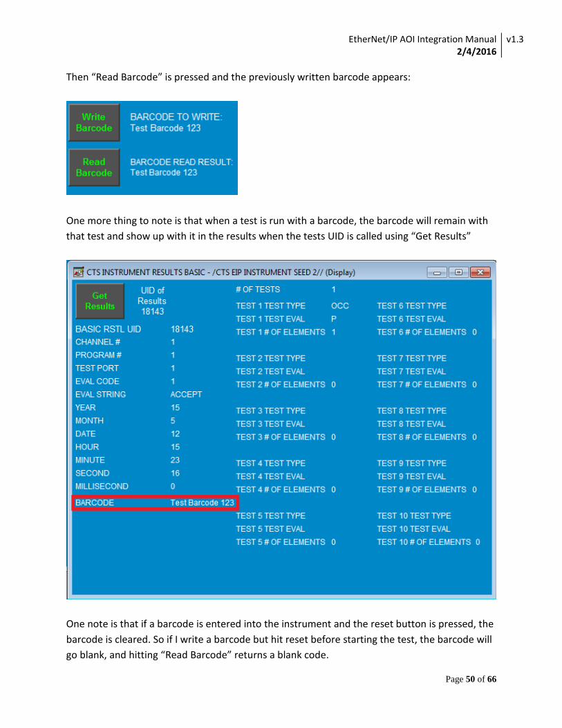
Then “Read Barcode” is pressed and the previously written barcode appears:
One more thing to note is that when a test is run with a barcode, the barcode will remain with that test and show up with it in the results when the tests UID is called using “Get Results”
One note is that if a barcode is entered into the instrument and the reset button is pressed, the barcode is cleared. So if I write a barcode but hit reset before starting the test, the barcode will go blank, and hitting “Read Barcode” returns a blank code.
EtherNet/IP AOI Integration Manual 2/4/2016
v1.3
Page 51 of 66
Parent and Sequential Programming
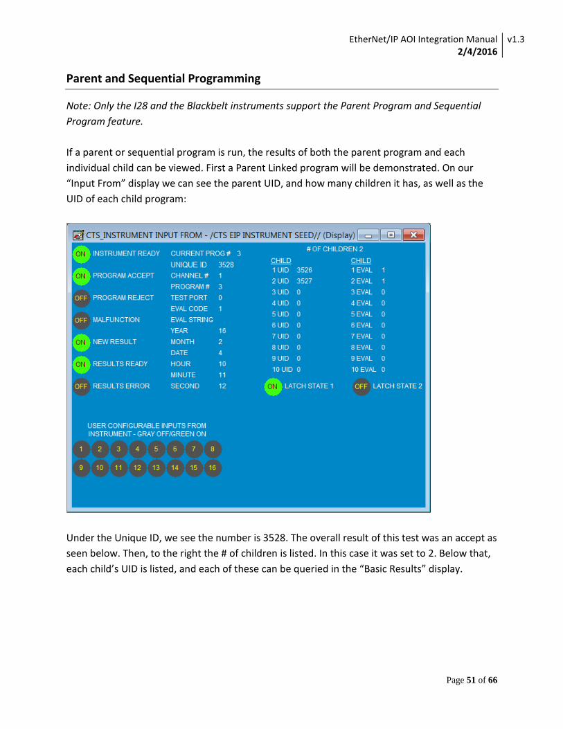
Note: Only the I28 and the Blackbelt instruments support the Parent Program and Sequential Program feature. If a parent or sequential program is run, the results of both the parent program and each individual child can be viewed. First a Parent Linked program will be demonstrated. On our “Input From” display we can see the parent UID, and how many children it has, as well as the UID of each child program:
Under the Unique ID, we see the number is 3528. The overall result of this test was an accept as seen below. Then, to the right the # of children is listed. In this case it was set to 2. Below that, each child’s UID is listed, and each of these can be queried in the “Basic Results” display.
EtherNet/IP AOI Integration Manual 2/4/2016
v1.3
Page 52 of 66
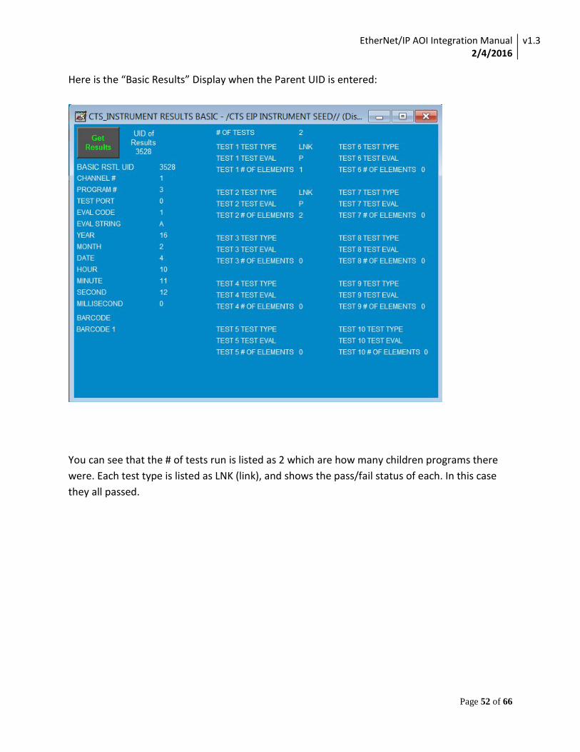
Here is the “Basic Results” Display when the Parent UID is entered:
You can see that the # of tests run is listed as 2 which are how many children programs there were. Each test type is listed as LNK (link), and shows the pass/fail status of each. In this case they all passed.

EtherNet/IP AOI Integration Manual 2/4/2016
v1.3
Page 53 of 66
If we reference the “Input From” display we can look at the UID of each child program and query the results for it. So, for example, we wanted to look at the specific results of 3526:

EtherNet/IP AOI Integration Manual 2/4/2016
v1.3
Page 54 of 66
This shows us the specific type of test this child program was (In this case a Pressure Decay Leak Standard), as well as the pass/fail status again. Expanding on this, we can view the detailed results of a child program:
This particular Pressure Decay test had 15 different detailed elements, which is listed at the top, and we can see the name of each element as well as the unit being measured and measured value for each element of the child program.
EtherNet/IP AOI Integration Manual 2/4/2016
v1.3
Page 55 of 66
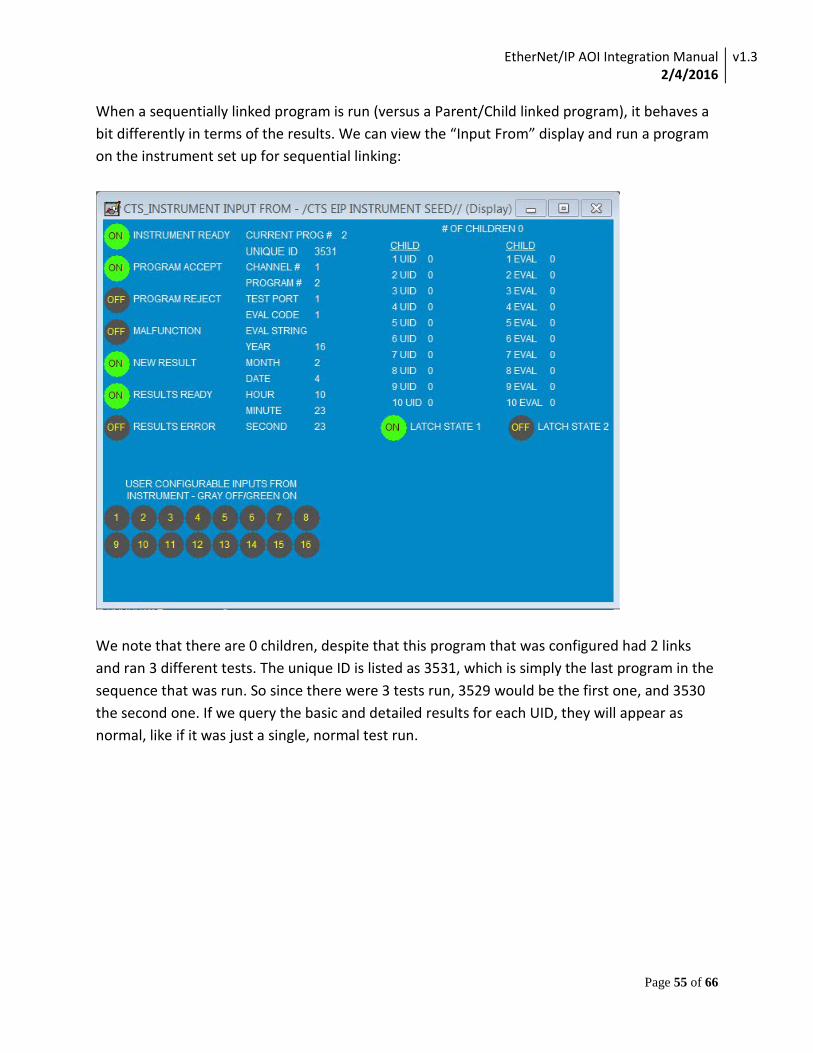
When a sequentially linked program is run (versus a Parent/Child linked program), it behaves a bit differently in terms of the results. We can view the “Input From” display and run a program on the instrument set up for sequential linking:
We note that there are 0 children, despite that this program that was configured had 2 links and ran 3 different tests. The unique ID is listed as 3531, which is simply the last program in the sequence that was run. So since there were 3 tests run, 3529 would be the first one, and 3530 the second one. If we query the basic and detailed results for each UID, they will appear as normal, like if it was just a single, normal test run.
EtherNet/IP AOI Integration Manual 2/4/2016
v1.3
Page 56 of 66
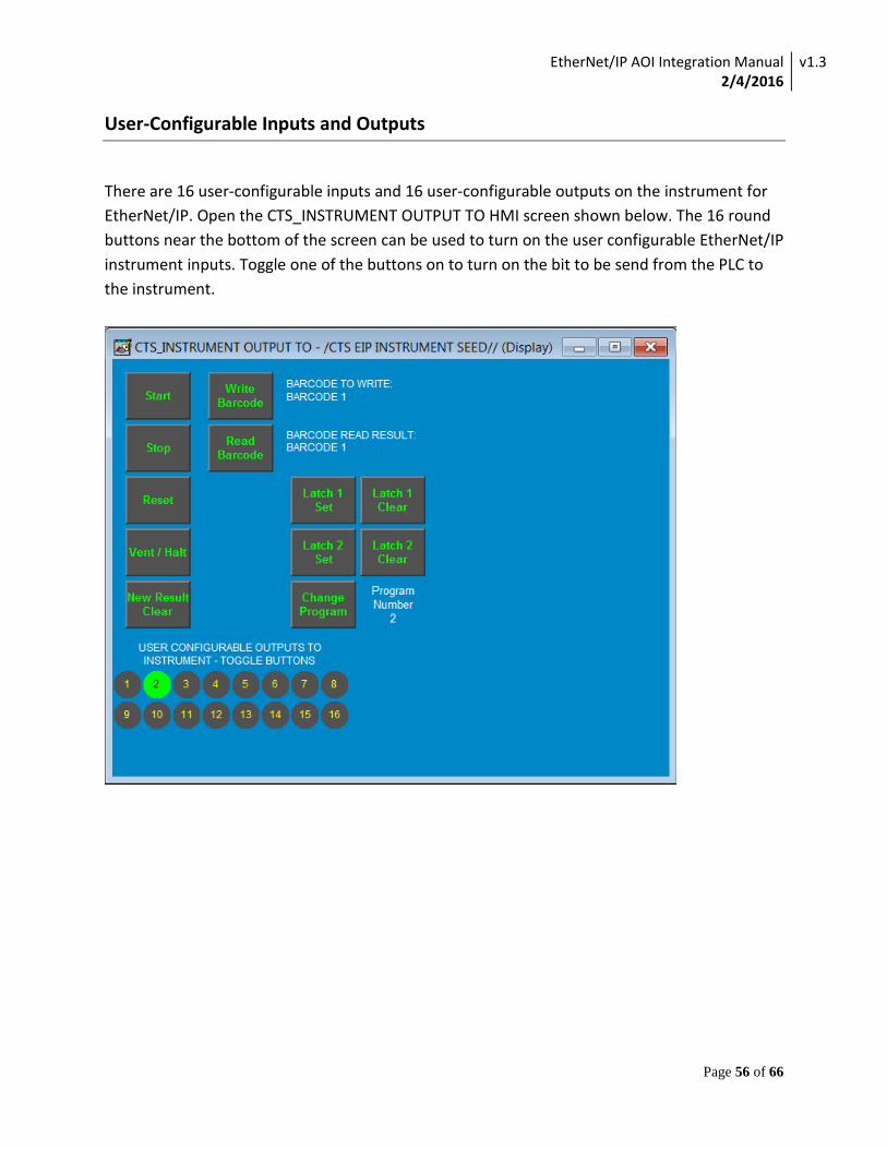
User-Configurable Inputs and Outputs
There are 16 user-configurable inputs and 16 user-configurable outputs on the instrument for EtherNet/IP. Open the CTS_INSTRUMENT OUTPUT TO HMI screen shown below. The 16 round buttons near the bottom of the screen can be used to turn on the user configurable EtherNet/IP instrument inputs. Toggle one of the buttons on to turn on the bit to be send from the PLC to the instrument.
EtherNet/IP AOI Integration Manual 2/4/2016
v1.3
Page 57 of 66
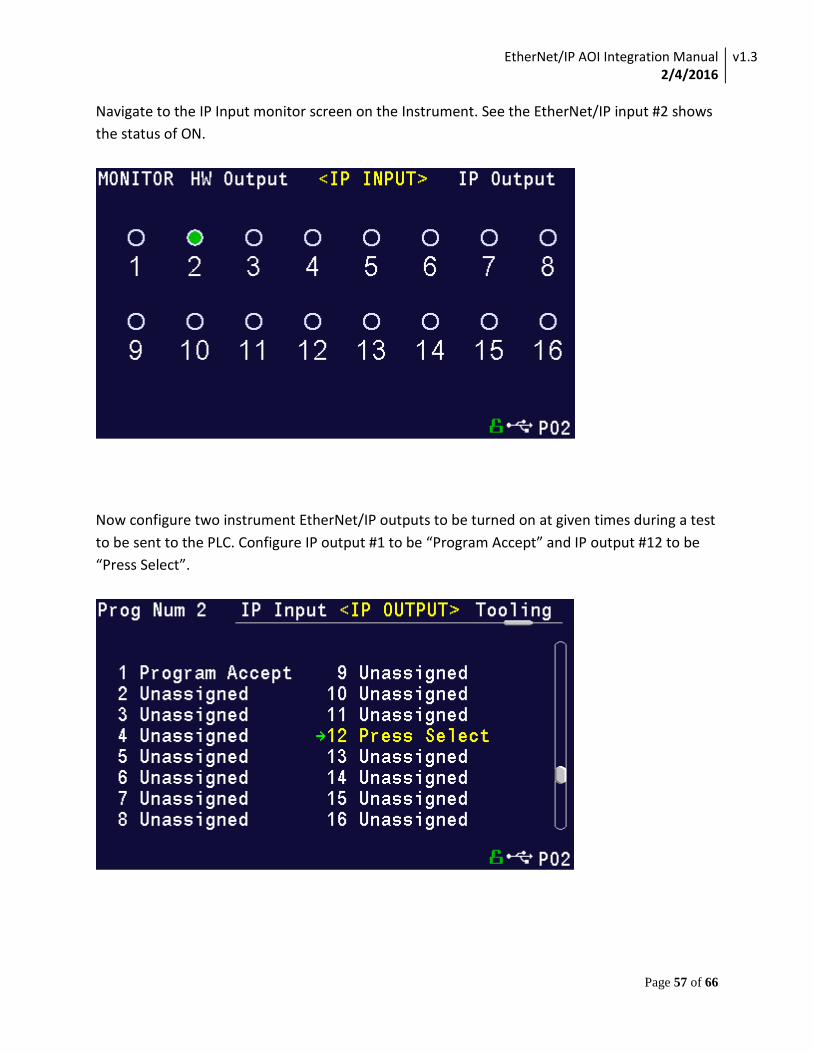
Navigate to the IP Input monitor screen on the Instrument. See the EtherNet/IP input #2 shows the status of ON.
Now configure two instrument EtherNet/IP outputs to be turned on at given times during a test to be sent to the PLC. Configure IP output #1 to be “Program Accept” and IP output #12 to be “Press Select”.
EtherNet/IP AOI Integration Manual 2/4/2016
v1.3
Page 58 of 66
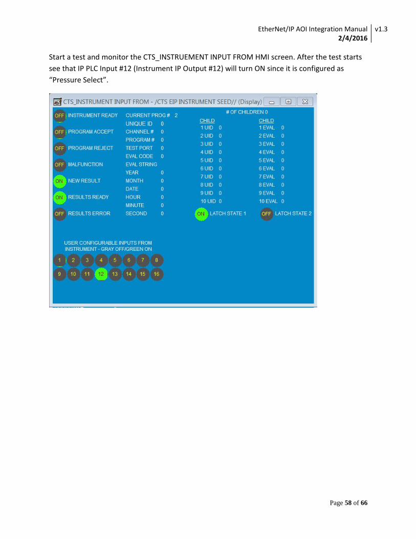
Start a test and monitor the CTS_INSTRUEMENT INPUT FROM HMI screen. After the test starts see that IP PLC Input #12 (Instrument IP Output #12) will turn ON since it is configured as “Pressure Select”.
EtherNet/IP AOI Integration Manual 2/4/2016
v1.3
Page 59 of 66
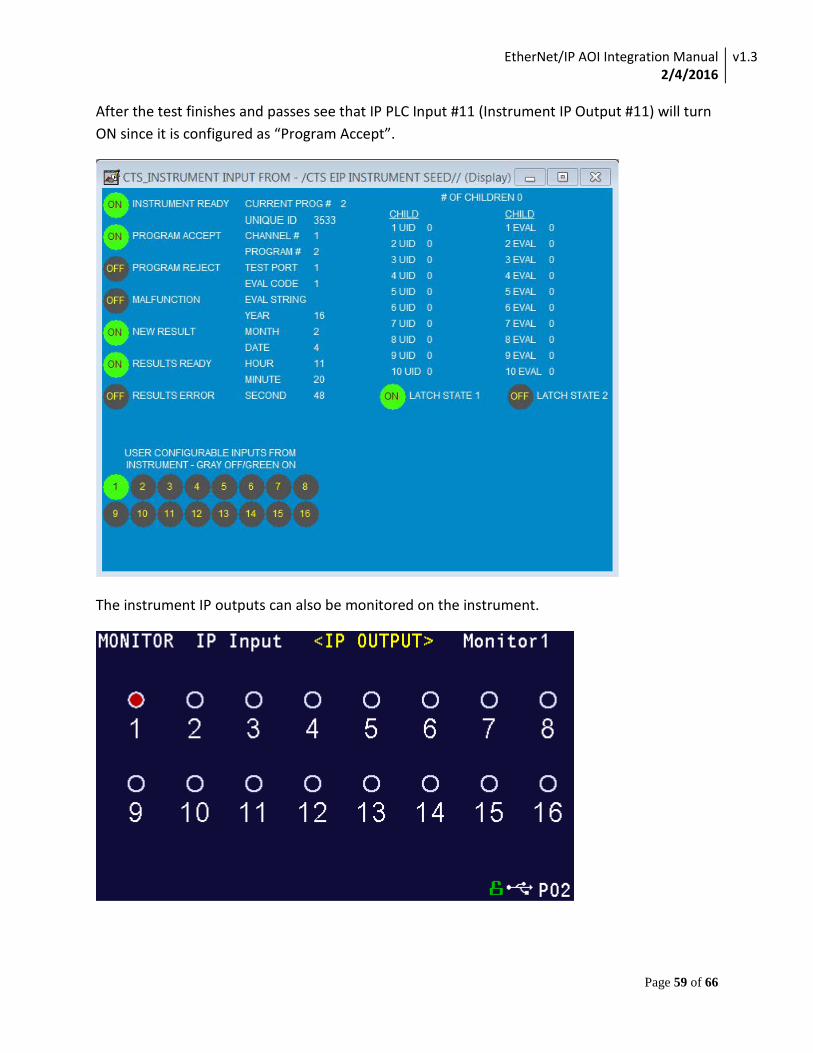
After the test finishes and passes see that IP PLC Input #11 (Instrument IP Output #11) will turn ON since it is configured as “Program Accept”.
The instrument IP outputs can also be monitored on the instrument.
EtherNet/IP AOI Integration Manual 2/4/2016
v1.3
Page 60 of 66
Appendix
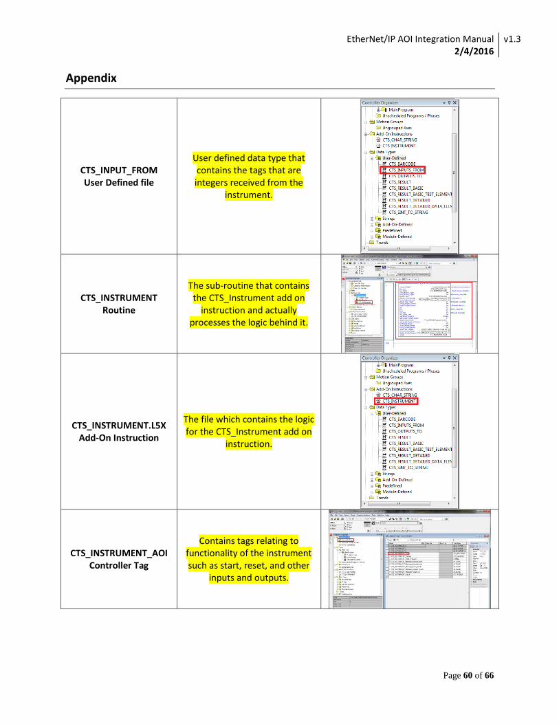
CTS_INPUT_FROM User Defined file
User defined data type that contains the tags that are integers received from the
instrument.
CTS_INSTRUMENT Routine
The sub-routine that contains the CTS_Instrument add on
instruction and actually processes the logic behind it.
CTS_INSTRUMENT.L5X Add-On Instruction
The file which contains the logic for the CTS_Instrument add on
instruction.
CTS_INSTRUMENT_AOI Controller Tag
Contains tags relating to functionality of the instrument such as start, reset, and other
inputs and outputs.
EtherNet/IP AOI Integration Manual 2/4/2016
v1.3
Page 61 of 66
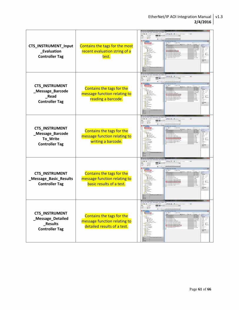
CTS_INSTRUMENT_Input _Evaluation
Controller Tag
Contains the tags for the most recent evaluation string of a
test.
CTS_INSTRUMENT _Message_Barcode
_Read Controller Tag
Contains the tags for the message function relating to
reading a barcode.
CTS_INSTRUMENT _Message_Barcode
To_Write Controller Tag
Contains the tags for the message function relating to
writing a barcode.
CTS_INSTRUMENT _Message_Basic_Results
Controller Tag
Contains the tags for the message function relating to
basic results of a test.
CTS_INSTRUMENT _Message_Detailed
_Results Controller Tag
Contains the tags for the message function relating to
detailed results of a test.
EtherNet/IP AOI Integration Manual 2/4/2016
v1.3
Page 62 of 66
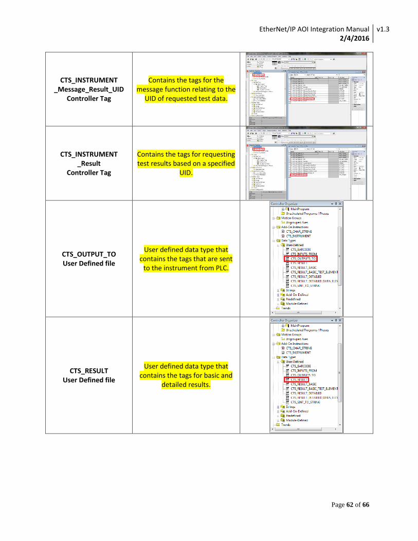
CTS_INSTRUMENT _Message_Result_UID
Controller Tag
Contains the tags for the message function relating to the
UID of requested test data.
CTS_INSTRUMENT _Result
Controller Tag
Contains the tags for requesting test results based on a specified
UID.
CTS_OUTPUT_TO User Defined file
User defined data type that contains the tags that are sent
to the instrument from PLC.
CTS_RESULT User Defined file
User defined data type that contains the tags for basic and
detailed results.
EtherNet/IP AOI Integration Manual 2/4/2016
v1.3
Page 63 of 66
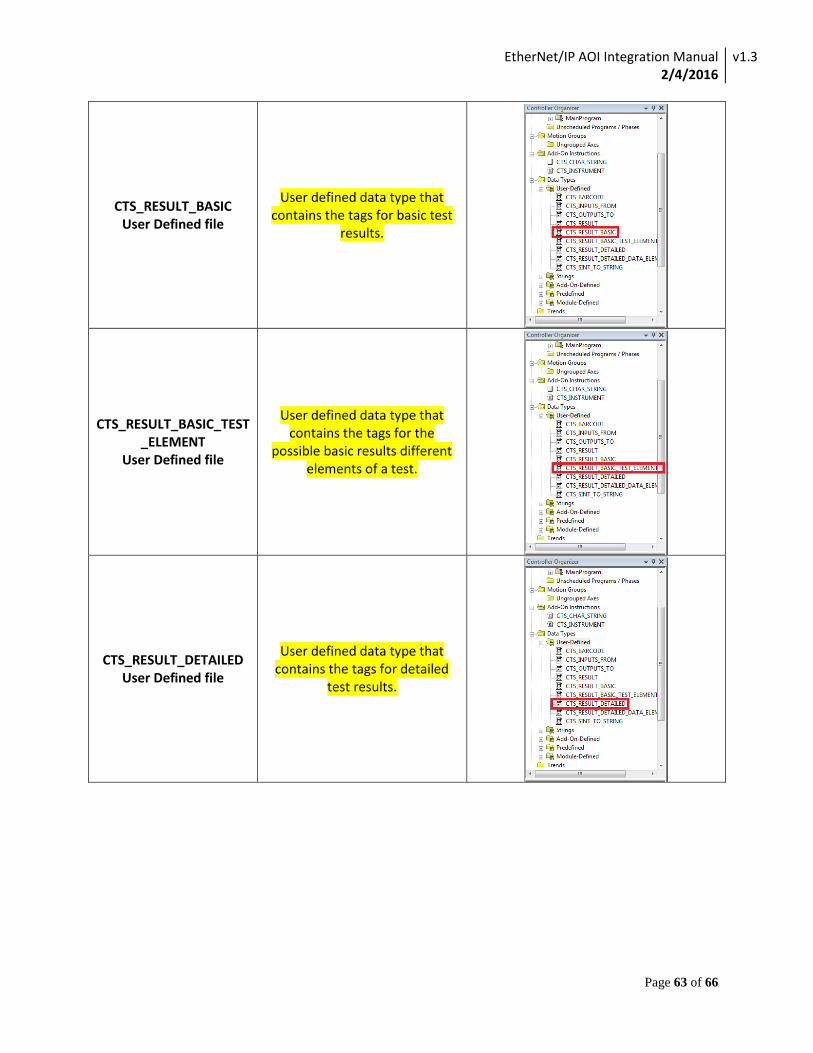
CTS_RESULT_BASIC User Defined file
User defined data type that contains the tags for basic test
results.
CTS_RESULT_BASIC_TEST_ELEMENT
User Defined file
User defined data type that contains the tags for the
possible basic results different elements of a test.
CTS_RESULT_DETAILED User Defined file
User defined data type that contains the tags for detailed
test results.
EtherNet/IP AOI Integration Manual 2/4/2016
v1.3
Page 64 of 66
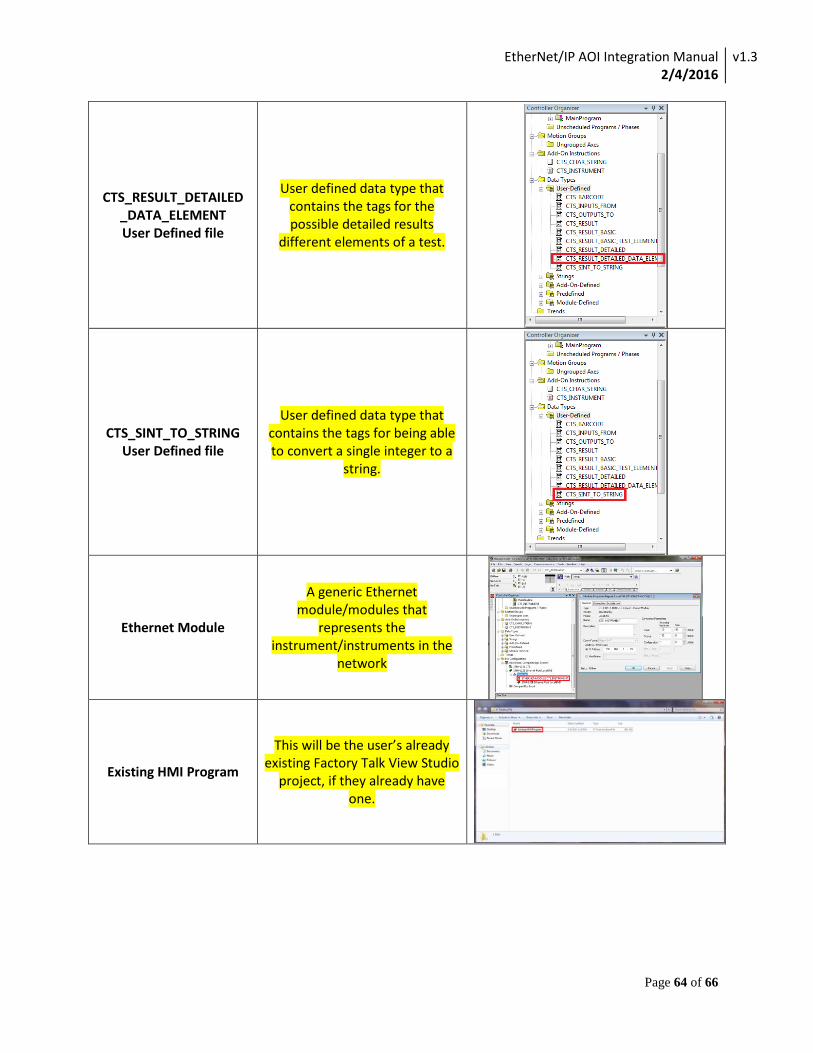
CTS_RESULT_DETAILED _DATA_ELEMENT User Defined file
User defined data type that contains the tags for the possible detailed results
different elements of a test.
CTS_SINT_TO_STRING User Defined file
User defined data type that contains the tags for being able to convert a single integer to a
string.
Ethernet Module
A generic Ethernet module/modules that
represents the instrument/instruments in the
network
Existing HMI Program
This will be the user’s already existing Factory Talk View Studio
project, if they already have one.
EtherNet/IP AOI Integration Manual 2/4/2016
v1.3
Page 65 of 66
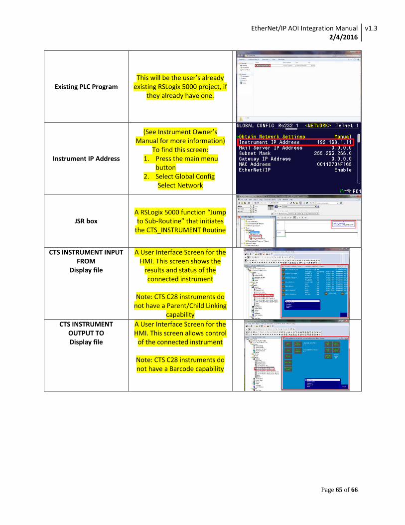
Existing PLC Program This will be the user’s already
existing RSLogix 5000 project, if they already have one.
Instrument IP Address
(See Instrument Owner’s Manual for more information)
To find this screen: 1. Press the main menu
button 2. Select Global Config
Select Network
JSR box A RSLogix 5000 function “Jump to Sub-Routine” that initiates
the CTS_INSTRUMENT Routine
CTS INSTRUMENT INPUT
FROM Display file
A User Interface Screen for the HMI. This screen shows the
results and status of the connected instrument
Note: CTS C28 instruments do
not have a Parent/Child Linking capability
CTS INSTRUMENT OUTPUT TO Display file
A User Interface Screen for the HMI. This screen allows control
of the connected instrument
Note: CTS C28 instruments do not have a Barcode capability

EtherNet/IP AOI Integration Manual 2/4/2016
v1.3
Page 66 of 66
CTS INSTRUMENT RESULTS BASIC
Display file
A User Interface Screen for the HMI. This screen provides a
history of test results. By touching “UID of Results”
entering a number and touching “Get Results” a report of the entered test will be displayed
Note: CTS C28 instruments do not have a Barcode capability
CTS INSTRUMENT RESULTS DETAILED 1
Display file
A User Interface Screen for the HMI. This screen shows additional data from the
specified test on the Results Basic.
CTS INSTRUMENT RESULTS DETAILED 2
Display file
A User Interface Screen for the HMI. This screen is an extension from Results Detailed 1 if a test has more than 15 elements or
links.
![Mower County transcript. (Lansing, Minn.) 1897-11-17 [p ].€¦ · cts cts cts cts cts cts cts cts cts JACKETS. Ladies' heavy Boucle Jackets, the latest style, and worth $5.00, only](https://img.pdfslide.net/doc/110x75/5fce2fde3593f56f3c130835/mower-county-transcript-lansing-minn-1897-11-17-p-cts-cts-cts-cts-cts-cts.jpg)


![Como Configurar Un Generic Module ETH en RSLogix5000 IM0047281[1]](https://img.pdfslide.net/doc/110x75/56d6bef41a28ab301694496f/como-configurar-un-generic-module-eth-en-rslogix5000-im00472811.jpg)